1
MDINK32/DINK32 User’s
Guide
Interactive Debugger for PowerPC Microprocessors
Motorola
RISC Applications
Release Date: August 30, 2000
Updated: August 31, 2000
Version 12.0
Revision 1.0
Altivec Enabled
.
-1
MOTOROLA MDINK32/DINK32 Version 12.1
User’s Guide
© Copyright Motorola, Inc. 1993-2000
ALL RIGHTS RESERVED
You are hereby granted a copyright license to use, modify, and distribute the SOFTWARE so
long as this entire notice is retained without alteration in any modified and/or redistributed versions, and that such modified versions are clearly identified as such. No licenses are granted by
implication or otherwise under any patents or trademarks of Motorola, Inc.
The SOFTWARE is provided on an “AS IS” basis and without warranty. To the maximum extent
permitted by applicable law, MOTOROLA DISCLAIMS ALL WARRANTIES WHETHER
EXPRESSED OR IMPLIED, INCLUDING IMPLIED WARRANTIES OF MERCHANTABILITY OR FITNESS FOR A PARTICULAR PURPOSE AND ANY WARRANTY AGAINST
INFRINGEMENT WITH REGARD TO THE SOFTWARE (INCLUDING ANY MODIFIED
VERSIONS THEREOF) AND ANY ACCOMPANYING WRITTEN MATERIALS.
To the maximum extent permitted by applicable law, IN NO EVENT SHALL MOTOROLA BE
LIABLE FOR ANY DAMAGES WHATSOEVER (INCLUDING WITHOUT LIMITATION,
DAMAGES FOR LOSS OF BUSINESS PROFITS, BUSINESS INTERRUPTION, LOSS OF
BUSINESS INFORMATION, OR OTHER PECUNIARY LOSS) ARISING OUT OF THE USE
OR INABILITY TO USE THE SOFTWARE. Motorola assumes no responsibility for the maintenance and support of the SOFTWARE.
-2
Dink32 R12 User’s Manual
Chapter 1 DINK32 User’s Guide Index
Chapter 1, “DINK32 User’s Guide Index"
Chapter 2, “Introduction"
Chapter 3, “MDINK32/DINK32 Features"
Chapter 4, “MDINK32/DINK32 Commands"
Chapter 5, “DINK32 Command Form Summary"
Chapter 6, “Utilities"
Chapter 7, “User Program Execution"
Chapter 8, “Errors and Exceptions"
Chapter 9, “Restrictions"
Chapter 10, “Known Bugs"
Appendix A, “Adding Commands and Arguments"
Appendix B, “Adding ERROR Groups to MDINK/DINK32"
Appendix C, “History of MDINK32/DINK32 changes"
Appendix D, “S-Record Format Description"
Appendix E, “Example Code"
Appendix F, “Updating DINK32 from the Web"
Appendix G, “Dynamic functions such as printf and variables such as memSpeed"
Appendix H, “MPC8240 (Kahlua) Drivers"
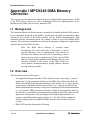
Appendix I, “MPC8240 DMA Memory Controller."
Appendix J, “MPC8240 I2C Driver Library."
Appendix K, “MPC8240 I2O Doorbell Driver"
Appendix L, “MPC8240 EPIC Interrupt Driver"
Appendix M, “Converting Dink32 to Little Endian"
Chapter 1. DINK32 User’s Guide Index
1-3
Chapter 2
Introduction
DINK is an acronym for Demonstrative Interactive Nano Kernel.
DINK32 is a flexible software tool enabling evaluation and debugging of the PowerPC
32-bit microprocessors. The introduction of the PowerPC microprocessor architecture
provided an opportunity to create an interactive debugger independent from previous debug
monitors. Since the family of PowerPC microprocessors spans a wide market range,
DINK32 has to be extensible and portable, as well as being specific enough to be useful for
a wide variety of applications. It is designed to be both a hardware and software debugging
tool. DINK32 was written in ANSI C and built with modular routines around a central core.
Only a few necessary functions were written in PowerPC assembly. This document
describes the DINK32 software, the DINK32 command set, utilities, user program
execution, errors and exceptions, and restrictions.
MDINK32 (Minimal DINK32) is a limited version of DINK32. It’s major purpose is to
download versions of DINK32 to the board. Currently, MDINK32 is only available on
Excimer and Maximer boards. MDINK32 is supplied with the board. It is burned into sector
A15, which is protected. The user can obtain new executable versions of DINK32 from the
web site and download them onto the Excimer and Maximer board via MDINK32. New
versions of MDINK32 are only available by returning the board to Motorola for an
MDINK32 upgrade or building it from the source code.
2-4
Dink32 R12 User’s Manual
Chapter 3 MDINK32/DINK32 Features
The MDINK32/DINK32 software package provides:
•
Supports the MPC601, MPC603, MPC603e, MPC604, MPC604e, MPC740,
MPC750, and the MPC7400.
•
Modification and display of general purpose, floating point, altivec, and special
purpose registers.
•
Assembly and disassembly of PowerPC instructions for modification and display of
code.
•
Modification, display, and movement of system memory.
•
A simplified breakpoint command, allowing setting, displaying, and removing
breakpoints.
•
Single-step trace and continued execution from a specified address.
•
Automatic decompression of compressed s-record files while downloading
•
Extensive on-line help.
•
Ability to execute user-assembled and/or downloaded software in a controlled
environment.
•
Logging function for generating a transcript of a debugging session.
•
Register set includes all of the PowerPC implementation specific registers.
•
Modification of memory at byte, half-word, word and double-word lengths.
•
Extensive support for the MPC 60x, MPC 740, MPC750, MPC7400 simplified or
extended mnemonics during assembly and disassembly of PowerPC instructions.
•
Ability to input immediate values to the assembler as binary, decimal, or
hexadecimal.
•
Command line download functionality that allows the user to select the download
port and then send the data.
•
An assembler and disassembler that understands branch labels and the ability to see
and clear the branch table that DINK32 is using while assembling and disassembling
PowerPC instructions.
•
Ability to read and write MPC106 configuration registers. (Not supported on
Excimer and Maximer).
•
Support for PCI with new “pci-” commands. (Not supported in minimal builds, i.e.
Excimer and Maximer).
•
Support for Excimer and Maximer flash, fl –dsi and –se, and automatically detect
flash on Revision 2 versus 3 of the board. fl -dsi has been expanded to display the
memory range for each sector.
Chapter 3. MDINK32/DINK32 Features
3-5
MDINK32 Overview
•
Support for Excimer and Maximer flash, fl -sp and -su.
•
Support for Max chip and altivec registers and instructions.
•
Support for Kalua chip.
•
Support for MPC107 Memory bridge.
•
Support for dynamically assigned dink function addresses and variables for
downloaded programs, see Appendix G, “Dynamic functions such as printf and
variables such as memSpeed".
•
Support for Yellowknife and Sandpoint flash ROMs, fu command.
3.1 MDINK32 Overview
The following sections describe the MDINK32 methodology and limited command set., the
minimum required hardware configuration, and the memory model. MDINK32 is only
available with the Excimer and Maximer platform. The current release of MDINK32 is
Version 10.7.
3.2 New features for MDINK32 V12.1
No new functionality.
There is a problem with this release, it may not jump correctly to ffc00000 and fails to start dink32.
3.3 MDINK32 Design Methodology
The MDINK32 program’s only purpose is to download DINK32 programs. MDINK32 is
loaded at 0xfff00000 and begins execution at 0xfff00100. It’s limited command set is
designed to allow easy loading of DINK32 or other programs into FLASH or ROM
memory and starting those programs.
See F.3, “Settings for terminal emulators" for instructions in connecting to a terminal
emulator.
See Appendix F, “Updating DINK32 from the Web" for information on obtaining new
versions of DINK32.
3.4 Hardware Configuration Requirements
This MDINK32 software package can be executed on the same microprocessor boards that
support DINK32, which include the following devices and minimum memory
configuration:
•
3-6
PowerPC™ 601, 603(e), 604(e), 740/750, MPC7400 microprocessors
Dink32 R12 User’s Manual
MDINK32 Software Build Process
•
National Semiconductor PC87308 DUART (Yellowknife and Sandpoint Reference
Design).or National Semiconductor 16552 DUART (Excimer and Maximer
Minimal Evaluation Board)
•
512 K-byte EPROM or Flash
•
512 K-byte RAM
3.5 MDINK32 Software Build Process
MDINK32 can be built from the dink source base. Information for building MDINK32 is
given in the DINK32 build section. There is only one version of mdink32 for all Excimer
and Maximer boards. Flash memory is automatically detected.
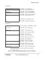
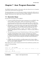
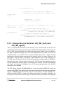
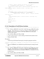
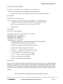
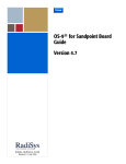
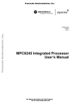
3.6 MDINK32 Memory Model
See Figure 3-3., “MDINK32/DINK32 Memory Model - Excimer and Maximer".
The following sections describe the DINK32 design methodology, the minimum required
hardware configuration, and the memory model. The current release of DINK32 is Version
12.0.
3.7 New features for DINK32 V12.1
1. Support for Yellowknife and Sandpoint flash ROM devices.
2. Reorganized all demos into one demos directory..
3. All User SPRs are now initialized during booting.
4. Application programs can now always safely return to DINK at completion.
5. dev epic has been enhanced.
6. Two dink variables, memSpeed and processor_type have been added to the
dink_transfer_table for dynamic access.
7. dl now supports the binary download facility.
8. Support for the MPC755 I/D bats 4:7
9. New commands, id and mc.
3.8 DINK32 Design Methodology
The modular design of the DINK32 program, its extensive commenting, and its design
methodology enable efficient user modification of the code. Thus, DINK32 provides a
flexible and powerful framework for users who desire additional functionality.
See F.3, “Settings for terminal emulators" for instructions in connecting to a terminal
emulator.
Chapter 3. MDINK32/DINK32 Features
3-7
DINK Software Build Process
Hardware Configuration Requirements
This DINK32 software package can be executed on microprocessor boards that include the
following devices and minimum memory configuration:
•
PowerPC™ 601, 603(e), 604(e), 740/750, 7400 microprocessors
•
National Semiconductor PC87308 DUART (Yellowknife and Sandpoint Reference
Design). or National Semiconductor 16552 DUART (Excimer and Maximer
Minimal Evaluation Board)
•
512 K-byte EPROM or Flash
•
32 M-byte RAM
3.9 DINK Software Build Process
There are two types of platforms.
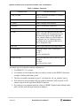
1. YellowKnife and Sandpoint. DINK32 is loaded at 0xfff00000. The config.h file
must set the RESET_BASE macro to RESET_BASE_OTHERS as shown in
Table 3-1., “RESET_BASE value"
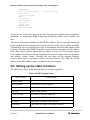
Table 3-1. RESET_BASE value
Macro Name
Value
RESET_BASE_OTHERS
0xFFF0 (default)
RESET_BASE_EXCIMER
0xFFC0
2. Excimer and Maximer. The config.h file must set the RESET_BASE macro to
RESET_BASE_EXCIMER as shown in Table 3-1., “RESET_BASE value"
DINK32 is a sophisticated debug ROM program. Most hardware specific features such as
the specific PowerPC processor, the memory map, the target platforms, etc. are
automatically detected at run time. This flexibility allows a single version of DINK32 to
run on different platforms with different processors; for example the same version of
DINK32 will boot the Yellowknife X2 platform with memory map A, the Yellowknife X4
platform with memory Map B, the Sandpoint, as well as the Excimer and Maximer
platforms with all the supported PowerPC processors.
The ROM device on the Yellowknife and Sandpoint system is the Plastic Leaded Chip
Carrier (PLCC) device. Upgrading the firmware on such system could be as easy as
removing and replacing the old ROM with the new one. The ROM devices on the Excimer
and Maximer platform however are the thin small surface mount packages (TSSOP). It is
not easy to remove such devices on the target hardware for upgrading. To solve this
problem, Motorola provides a smaller version of DINK32 called MDINK. The main
purpose of mdink is to download DINK32 or other boot program to ROM, thus it provides
a robust way for upgrading the firmware.
3-8
Dink32 R12 User’s Manual
DINK Software Build Process
There are two different versions of DINK:
1. DINK32 provides the capability to download and debug application programs,
2. MDINK32 provides the capability to download and upgrade firmware.
Only DINK32 is available in executable form. It is delivered in the following eight file
formats as shown in Table 3-2., “DINK32 File Formats"
Table 3-2. DINK32 File Formats
Board
S record
S Record (-g)
elf
elf/dwarf (-g)
Yellowknife and Sandpoint
dinkyk.src
dinkyk_g.src
dinkyk
dinkyk_g
Excimer
dinkex.src
dinkex_g.src
dinkex
dinkex_g
The source files can be used to build DINK32 or MDINK32.
The source files are *.c, *.s, and *.h.
Other files are makefile and READ_ME
Motorola uses the Metaware tool set to build MDINK32 and DINK32 in a UNIX
environment. The syntax of the makefile, therefore, complies with the make program
available on UNIX machines. The command to build DINK32 on a UNIX command line
is "make dink", and the command to build MDINK32 is "make mdink".
MDINK32 is a subset of DINK32. Both versions share many source files. Of all the files
that contribute to the making of MDINK32, the files that MDINK32 does not share with
DINK32 is mpar_tb.c and mhelp.c. DINK32's version of mpar_tb.c is par_tb.c and mhelp.c
is help.c.
Both can also be build on UNIX with the GNU gcc tool set using makefile_gcc, and on a
PC/NT with the Metaware tool set using makefile_pc.
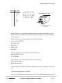
The source files and the makefile of DINK32 and MDINK32 reside in the same directory
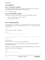
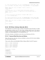
structure. However, the object files (*.o), the ELF file and S-record file of each version
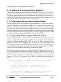
reside on a different directory. When the "make dink" command is executed, the "dink_dir"
directory is created, and the output files produced by "make" are put in "dink_dir".
Likewise, when the "make mdink" command is executed, the "mdink_dir" directory is
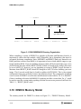
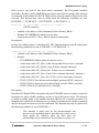
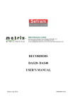
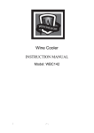
created, and the output files are put in "mdink_dir" (see Figure 3-1).
In addition, the makefile, makefile_pc, is used to build on the PC (windowns) platform, and
the makefile_gcc is used to build on UNIX with a GNU gcc compiler.
Chapter 3. MDINK32/DINK32 Features
3-9
DINK32 Memory Model
.../DINK32
dink_dir
*.h
*.c
*.s
mdink_dir
drivers
epic dma i2o i2c
board.h
*.o
dink32.src
dink32
board.h *.o
mdink32.src
mdink32
Figure 3-1. DINK32/MDINK32 Directory Organization
When compiling a version of DINK32 to upgrade an Excimer and Maximer board it is
important to realize that this module, while relocatable, has a dependency that must be
accounted for during compilation. Since, MDINK32 and DINK32 both copy themselves to
RAM (and then execute from RAM) it is important to know which address range to copy
from FLASH to RAM. If you are building an image which will be located at the reset vector
(0xFFF00100) then the #define RESET_BASE (which is located in the config.h file) must
be set to 0xFFF0. If, however, you are upgrading a version of DINK32 on an Excimer or
Maximer board RESET_BASE should be changed to 0xFFC0 before building your new
image. This S-record would then be loaded at address 0xFFC00000. This is the original
configuration that came with the Excimer and Maximer board. The command to download
a new version of DINK32 on an Excimer and Maximer board would be "dl -fl -o ffc00000"
if there is nothing at location 0xffc00000. If replacing an older version then “fw -e” would
be used to erase the version (and everything else that was not sector protected) in Flash. See
Table 3-1., “RESET_BASE value".
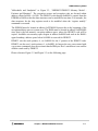
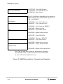
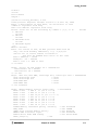
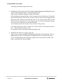
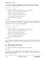
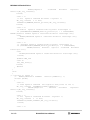
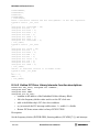
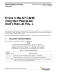
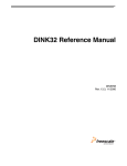
3.10 DINK32 Memory Model
The memory model for DINK32 is shown in Figure 3-2., “DINK32 Memory Model -
3-10
Dink32 R12 User’s Manual
DINK32 Memory Model
Yellowknife and Sandpoint" or Figure 3-3., “MDINK32/DINK32 Memory Model Excimer and Maximer". The exception vectors and exception code are located within
address offsets 0x0000 - 0x2100. The DINK32 code through 0x80000 is copied from the
EPROM to RAM so that the data structures can be modified at run time. For example, the
data structures for the chip registers need to be modified when the “register modify”
command is executed.
The EPROM must be located at address 0xFFF00000 because this is the beginning of the
exception address space at system reset. The RAM must be located at address 0x00000000
since that is the low-memory exception address space, where the DINK32 code will be
copied. Available user memory space begins at address 0x90000 and ends at the RAM’s
upper boundary; address space below 0x90000 is reserved for DINK32.
DINK32 sets the stack pointer, r1, to 0x80000 for the C portion of the DINK32 code.
DINK32 sets the user’s stack pointer, r1, to 0x8fff0. As long as the user, once started with
a go or trace command, does not use more than 0xfff0 bytes for it’s stack there is no conflict
with the stack used by DINK32.
Please reference Figure 3-2 and Figure 3-3 on the following page.
Chapter 3. MDINK32/DINK32 Features
3-11
DINK32 Memory Model
512 K-byte EPROM
0xFFFFFFFF - End of ROM space
0xFFF8FFFF - End of DINK32 Code
0xFFF00100 - Reset Vector
Top of User Memory (depending on the amount of
RAM installed); 1M = 0x000FFFFF, Typical size is
32M = 0x00200000
User Memory
DINK32 stack
0x00090000 - Start of User Memory
0x0008FFFF - Top of Stack for user
0x00080000 - Top of Stack for DINK32
0x00070000 - Bottom of stack
0x0006FFFF - Top of.data section
.data
0x00040000 - Bottom of.data section
0x000303FF - Top of RODATA
0x0002FD00 - Bottom of RODATA
0x0002FFFF - Top of.text section
.text
0x00003000 - Bottom of.text section
0x00002FFF - Top of Exception table
Exception table
0x00000000 - Bottom of Exception Table
Note: The .text and .data sections are approximates depending
on each build version. Actual locations can be ascertained from
the xref.txt file in the dink_dir directory.
Figure 3-2. DINK32 Memory Model - Yellowknife and Sandpoint
3-12
Dink32 R12 User’s Manual
DINK32 Memory Model
System ROM
4 Meg Flash ROM
0xFFFFFFFF - End of ROM space
0xFFF60000 - End of MDINK32 Code
MDINK32
User Flash Space
0xFFF00100 - Reset Vector (MDINK32)
0xFFEFFFFF - Top of User Flash Space
DINK32
0xFFC90000 - Bottom of User Flash Space
0xFFC8FFFF - End of DINK32 Code
0xFFC00100 - Start of DINK32 Code
0xFFC00000 - Beginning of Flash space
System RAM
Top of User Memory - 0x000FFFFF (1 Meg)
User Memory
0x00090000 - Start of User Memory
DINK32 stack
0x0008FFFF - Top of Stack for user
0x00080000 - Top of Stack for DINK32
0x00070000 - Bottom of stack
0x0006FFFF - Top of .data section
.data
0x00040000 - Bottom of .data section
0x00030000 - Top of RODATA
0x0002FD00 - Bottom of RODATA
0x0002FFFF - Top of .text section
.text
0x00003000 - Bottom of .text section
0x00002FFF - Top of Exception table
Exception table
0x00000000 - Bottom of Exception Table
Note: The .text and .data sections are approximates depending
on each build version.
Figure 3-3. MDINK32/DINK32 Memory Model - Excimer and Maximer
Chapter 3. MDINK32/DINK32 Features
3-13
Commands
Chapter 4 MDINK32/DINK32
Commands
This chapter describes the DINK32 user commands. The full command mnemonic is listed
in the upper left-hand corner and the short command (abbreviation) is listed next in smaller
type. All commands listed (except fw -e) are available to DINK32, those commands
available to MDINK32 are marked as MDINK32 Compatible.
Commands appear in boldface throughout this chapter.
Note: All addresses entered must be in hexadecimal but not preceded by “0x”.
Leading zeros will be added as needed.
Definitions
“MDINK32 Compatible”
This command is also available in MDINK32. Where commands are different between
MDINK32 and DINK32, the DINK32 format will be shown first.
“plus”
Usually implies that the command form includes “+”. This allows the command to continue
to the next stopping place appropriate for its functionality.
“range”
Indicates a two-address form, and usually signifies an inclusive area of code or memory that
will be operated on by the command.
“entire family”
Refers to a family of registers. The general purpose registers are a family of thirty two
32-bit registers, numbered 0 to 31. The floating point registers are a family of thirty-two
64-bit registers, numbered 0 to 31. The altivec registers are a family of thirty-two 128-bit
registers, numbered 0 to 31.The special purpose registers are not classified as a family due
to their architectural design.
“x”
Typing “x” will exit a command if DINK32 is in an interactive mode when a particular
command form is used.
4.1 Commands
4-14
Dink32 R12 User’s Manual
Commands
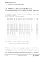
4.1.1
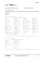
.(period)
repeat last command
.
MDINK32 Compatible
Typing a period will repeat the last command entered.
Example:
DIN K32 _75 0 >> tr ace 21 00
A R un Mod e or Tr ace ex cept ion ha s o ccur red .
Cur ren t i nstr uct ion Po inte r: 0x0 000 2104 st w r 13, 0xf ff8 (r0 1)
DIN K32 _75 0 >> tr ace +
A R un Mod e or Tr ace ex cept ion ha s o ccur red .
Cur ren t i nstr uct ion Po inte r: 0x0 000 2108 ad d r 03, r00 , r 01
DIN K32 _75 0 >> .
A R un Mod e or Tr ace ex cept ion ha s o ccur red .
Cur ren t i nstr uct ion Po inte r: 0x0 000 210c mf spr r0 4, s 027 4
DIN K32 _75 0 >>
Chapter 4. MDINK32/DINK32 Commands
4-15
Commands
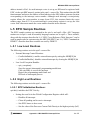
4.1.2
about
about
(M)DINK32 version information
MDINK32 Compatible
The version information for the current implementation of the DINK32 monitor will be
displayed on the terminal.
DINK32 Example:
DIN K32 _MP C603 ev >>a bou t
A R ese t E xcep tio n ’ 0x1 00’ ini tia ted thi s r est art
Cac hes En able d: [ L 1-I Cach e
L1- DCa che ]
DDD
III
D
D
I
D
D
I
D
D
I
DDD
III
N
N
NN
N
N N N
N
NN
N
N
K
K
K K
KK
K K
K
K
3 33
3
222
3
2
33
3
2
22
3
3 33
22
2 222 2
f or MPC 603 ev
Met awa re Buil d
Ver sio n 1 2, R evi sio n 0
Wri tte n b y
R ele ase d
Sy ste m
Pr oce sso r
:
:
:
:
Mot oro la’ s RI SC App lic atio ns, Au sti n, T X
Nov emb er 30, 199 9:
Wel com e t o Ex cim er. A Mini mum Sy ste m Po wer PC Des ign!
MPC 603 ev V12. 1 @ 13 3 M Hz, Mem ory @ 66 M Hz
Cop yri ght Mot oro la, In c. 1 993 , 1 994 , 19 95, 19 96, 199 7, 199 8, 1999
Cha nge s f or e ach re lea se, Err ata fo r di nk, Fu tur e En han cem ent s
and bu g f ixes ar e d ocu ment ed in the fil e h ist ory .c
DIN K32 _MP C603 ev >>
MDINK32 Example:
MDI NK3 2_6 03e >>a bou t
Dat a C ach e ha s b een en able d.. .
Ins tru cti on C ach e h as been en abl ed. ..
M
M
MM MM
M M M
M
M
4-16
DD D
III
D
D
I
D
D
I
D
D
I
N
N
NN
N
N N N
N
NN
K
K
K K
KK
K K
333
3
222
3
2
33
3
2
22
3
22
Dink32 R12 User’s Manual
Commands
M
M
DD D
III
N
N
K
K
333
2 222 2
fo r th e M PC6 03
Ver sio n 1 0, R evi sio n 7
Wri tte n b y : Mot oro la’ s RI SC App lic atio ns, Au sti n, T X
Rel eas ed : M arc h 1 , 1 999
Wel com e t o Ex cim er.
A Min imu m S yst em P owe rPC De sign !
Cop yri ght Mot oro la, In c. 1 993 , 1 994 , 19 95, 19 96, 199 7, 199 8
Chapter 4. MDINK32/DINK32 Commands
4-17
Commands
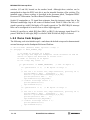
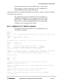
4.1.3
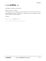
assemble
as
DINK32 mini-assembler
•
assemble address
•
assemble start +
•
assemble start - end
The mini-assembler for the DINK32 system will display the contents of memory at the
given location and enter interactive mode. The user will be queried for a valid mnemonics
and operands which will be assembled into a valid opcode and stored at that memory
location. A location can be left unmodified by typing <return> to pass over it.
The “plus” form of the command will allow the user to start assembling code at a given start
location and will be terminated at the end of memory. The “range” version will start at the
first address location and automatically terminate at the given end address.
At any point “x” can be entered as a mnemonic and assemble will terminate and return the
user to the DINK32 prompt.
Branch labels are recognized by the assembler as a word followed by a colon (:) at the
address currently being displayed by the assembler. The assembler tracks the current
branch labels and automatically calculates the address to be entered into future instructions.
The symtab,st instruction is available for manipulating the branch table in DINK32. Branch
labels within PowerPC assembly instructions will not be recognized by the assembler if the
branch label has not yet been entered into the table. The user may display the branch table
list with the st instruction.
The DINK32 assembler ignores any comments preceded by a ‘#’ and any “.org” and “.dc”
commands. The assembler does not interpret these lines as anything. It only ignores them.
The simplified mnemonics that DINK32 Version 10.5 understands is quite extensive. In
general, immediate values, including condition register bit offsets, are assumed to be
hexadecimal unless preceded by 0b (binary) or 0d (decimal). Floating point and general
purpose registers are recognized just like previous versions of DINK32 where the register
number may be preceded by an “r” (general purpose) or an “f” (floating point) but is not
necessary. Simplified branch mnemonics involving the condition registers may have the
condition register number preceded by “cr” but isn’t necessary. The assembler always
expects a “cr” field for compare and branch instructions where, according to the
architecture, cr0 is implied if a “cr” field is not given. DINK32 does not implement the
implied cr0 functionality of the simplified mnemonics.
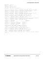
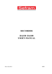
Examples:
4-18
Dink32 R12 User’s Manual
Commands
DIN K32 _60 3e > >as 60 100 +
0x0 006 010 0 0x 85f fff c4 lwz u
r 15, 0x ffc 4( r 31 )
rlm i
r00 ,r0 2,r 05,0 ,0
0x0 006 010 4 0 x00f fff a0 WOR D
0x 00f fff a0
l fd f0, 0x0e c5( r1)
0x0 006 010 8 0xf f00 40ef fsel .
f24 , f00 , f0 8, f0 3
r lwn m
r0, r13 ,r2 3,0x 1,0 xa
0x0 006 010 c 0x fe4 004 ff fnma dd.
f 18, f00 , f 19, f00
0x0 006 011 0 0x0 0ff ff0 1 WOR D
0 x00f fff 01
loop : #b ran ch la bel
0x0 006 011 0 0x 00f fff 01 BRAN CH LAB EL loop :
0x0 006 011 0 0 x00 ffff 01 WOR D
0x0 0ff ff0 1
ori r2 6,r2 ,0x fff
0x0 006 011 4 0x 00f fff 00 WORD
0 x00 fff f00
lf d f 00, 0x05 03( r0)
0x0 006 011 8 0x ef0 040 fd f nms ubs .
f24 , f0 0, f03 , f0 8
cmp w
cr3 ,r2 6,r 0
0x0 006 011 c 0x 7f0 000 ff WORD
0 x7f0 000 ff
bne cr 3,l oop
0x0 006 012 0 0x 22f fbf 80 subf ic
r 23, r31 , 0 xbf 80
x
VER IFY ING BRA NCH LA BEL S... ..
DON E V ERI FYIN G B RAN CH LABE LS!
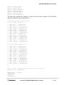
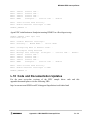
DIN K32 _60 3e > >st
Cur ren t l ist of DIN K b ranc h l abe ls:
KEYB OAR D:
0x0
get_ cha r:
0x1e 5e4
wr ite_ cha r:
0x5f ac
T Base Ini t:
0x39 c4
TBa seR eadL owe r:
0x39 e8
TBa seR eadU ppe r:
0x3a 04
C ach eInh ibi t:
0x3a 20
In vEn L1Dc ach e:
0x3a 40
Dis L1Dc ach e:
0x3a 88
In vEn L1Ic ach e:
0x3a ac
Dis L1Ic ach e:
0x3b 00
B urst Mod e:
0x3b fc
RamI nCB k:
0x3c 3c
Ra mInW Thr u:
0x3c 7c
d ink_ loo p:
0x56 60
din k_pr int f:
0x63 68
Cur ren t l ist of USE R b ranc h l abe ls:
loo p:
0x60 110
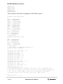
DIN K32 _60 3e > >as sem ble 603 00- 603 10
0x0 006 030 0 0x82 fff f00 l wz
r23 , 0xf f00 ( r31 )
f add 1 2 3
0x0 006 030 4 0x 00f fff 00 WORD
0 x00f fff 00
stw 1 2
0x0 006 030 8 0x ef0 080 ff fnma dds .
f 24, f00 , f 03, f16
sc
0x0 006 030 c 0xff 000 0ff f nmad d.
f24 , f00 , f03, f 00
bdn z
0x6 001 0
0x0 006 031 0 0x 04f fff 00 WORD
0 x04f fff 00
#Co mme nt
0x0 006 031 0 0x 04f fff 00 WORD
0 x04f fff 00
nop
DIN K32 _60 3e > >
DIN K32 _MA X >> as 700 10
Chapter 4. MDINK32/DINK32 Commands
4-19
Commands
0x0 007 001 0 0 xff8 000 ff fnm add .
f28 , f 00, f0 3, f00
DIN K32 _MA X >> as 700 14+
0x0 007 001 4 0x ff0 000 ff fnma dd.
f 24, f0 0, f 03, f0 0
0x0 007 001 8 0 x00f bff 00 WOR D
0x 00f bff0 0
v3, v19 ,v3 ,v31
0x0 007 001 c 0x 00ff ff0 0 WO RD
0x 00f fff 00
v30 ,v1 6,v 17,7
0x0 007 002 0 0x ff0 000 ff fnma dd.
f 24, f00 , f 03, f00
DIN K32 _MA X >> ds 700 10+
0x0 007 001 0 0x 106 006 04 mfvs cr
V3
0x0 007 001 4 0x 100 066 44 mtvs cr
V12
0x0 007 001 8 0x 107 31f e0 vmha dds hs V3, V19, V3, V31
0x0 007 001 c 0x 13d 089 ec vsld oi
V3 0,V1 6,V 17, 0x7
0x0 007 002 0 0x ff0 000 ff fnma dd.
f 24, f00 , f 03, f00
4-20
Dink32 R12 User’s Manual
mfv scr v3
mtvs cr v12
vm had dsh s
vs ldo i
x
Commands
4.1.4
bkpt
bp
set, delete, list breakpoints
bkpt
•
bkpt address
•
bkpt -d index
The bkpt command allows the user to set a breakpoint at a given address, delete a
breakpoint at a given index in the breakpoint list, and list the current breakpoints by index
and address.
Breakpoints allow the user to run an application program and stop execution when code at
the specified address is encountered. This command will set or delete only one breakpoint
at a time, and must be repeated for each breakpoint.
Setting a breakpoint will not remove a breakpoint from an address if a breakpoint already
exists there. Deleting a breakpoint from an invalid index has no effect. Breakpoints can be
set or deleted one at a time and all are displayed during a breakpoint list. A maximum of 20
breakpoints can be set in the system.
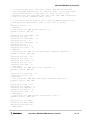
Examples:
DIN K32 _75 0 >> bk pt 601 00
Bre akp oin t se t a t 0 x00 0601 00
DIN K32 _75 0 >> bk pt
Cur ren t b reak poi nt lis t:
1. 0x0 006 0100
DIN K32 _75 0 >> bk pt -d 1
Bre akp oin t de let ed
DIN K32 _75 0 >> bk pt
Cur ren t B reak poi nt Lis t:
Chapter 4. MDINK32/DINK32 Commands
4-21
Commands
4.1.5
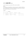
defalias
da
define alias
The runalias, ra, command is the companion to this command. While these commands, da
and ra, are still available, the env command is more flexible.
•
defalias
This command will allow the user to define an alias to a list of commands (separated by a
semicolon). Once the alias has been defined, runalias can be used instead of retyping the
list of commands. Only one alias may be set at a time, and using defalias a second time will
overwrite the previously aliased command list. Below is an example of using an alias to
single step and display registers.
Example:
DIN K32 _75 0 >> tr ace 21 00
A R un Mod e or Tr ace ex cept ion ha s o ccur red .
Cur ren t I nstr uct ion Po inte r: 0x0 000 2104 lw z r 03, 0x0 000 (r0 2)
DIN K32 _75 0 >> de fal ias
Cur ren t a lias de fin iti on:
New al ias : t r + ; r d r
Ali as def ined as : tr +; r d r
DIN K32 wil l no w sin gle ste p an d di spla y th e re gis ter set e ach tim e
run ali as is e nte red .
DIN K32 _75 0 >> ru nal ias
A R un Mod e or Tr ace ex cept ion ha s o ccur red .
Cur ren t I nstr uct ion Po inte r: 0x0 000 2108 ad d r 03, r00 , r 01
gpr 00: 0x 0000 000 0 g pr0 1: 0 x00 060 000
gpr 02: 0x 0000 000 0 g pr0 3: 0 x00 02b c00
gpr 04: 0x 0000 000 0 g pr0 5: 0 x00 000 000
gpr 06: 0x 0000 000 0 g pr0 7: 0 x00 000 000
gpr 08: 0x 0000 000 0 g pr0 9: 0 x00 000 000
gpr 10: 0x 0000 000 0 g pr1 1: 0 x00 000 000
gpr 12: 0x 0000 000 0 g pr1 3: 0 x00 000 000
gpr 14: 0x 0000 000 0 g pr1 5: 0 x00 000 000
gpr 16: 0x 0000 000 0 g pr1 7: 0 x00 000 000
gpr 18: 0x 0000 000 0 g pr1 9: 0 x00 000 000
gpr 20: 0x 0000 000 0 g pr2 1: 0 x00 000 000
gpr 22: 0x 0000 000 0 g pr2 3: 0 x00 000 000
gpr 24: 0x 0000 000 0 g pr2 5: 0 x00 000 000
gpr 26: 0x 0000 000 0 g pr2 7: 0 x00 000 000
gpr 28: 0x 0000 000 0 g pr2 9: 0 x00 000 000
gpr 30: 0x 0000 000 0 g pr3 1: 0 x00 000 000
4-22
Dink32 R12 User’s Manual
Commands
4.1.6
devdisp
dd
DINK32 Peripheral device display
dd,devdisp
•
dd [device [-b|-h|-w] addr1-addr2]
The devdisp command displays the contents of device registers in a manner similar to that
of the memory display command.
•
device
Is the name of the device. If not entered display all known devices
•
-b, -h, -w
for devices.
Set size of device accesses. If not specified, the default size is bytes
•
addr1
Is the starting address to display.
•
addr2
Is the optional ending address.
•
The dd command with no parameters will display a list of all the known devices.
Example:
DIN K32 _AR THUR >> dd
Devi ce
Sta rt
End
==== === =
=== ==== =
=== === ==
mem
000 0000 0
FFF FFF FF
nvra m
000 0000 0
000 00F FF
i2c
000 0000 0
000 000 7F
rtc
000 0000 0
000 000 0D
rtcr am
000 0000 E
000 000 FF
apc
000 0004 0
000 000 48
D INK3 2_A RTH UR >> d d n vra m 4 0
0 x004 0 1 4 3E 27 9C E E F A E9
... ... ... .... ...
0 x005 0 . ..
.. .
d d>x
DIN K32 _AR THUR >>
Siz es
=== ==
[BH W]
[B]
[B]
[B]
[B]
[B]
C0 04 6 B 2 A 87 08 9C 66 7 E
Chapter 4. MDINK32/DINK32 Commands
4-23
Commands
4.1.7
devmod
dm
DINK32 Peripheral device modify
devmod,dm
dm [device [-b|-h|-w] addr1-addr2]
The device modify command allows interactive modification of device data in registers
and/or indirect memory. The dd command operates similar to the mm command, with
some additional flexibility.
•
device
Is the name of the device. If not entered display all known devices
•
-b, -h, -w
for devices.
Set size of device accesses. If not specified, the default size is bytes
•
addr1
•
addr2
Is the optional ending address or if not specified then display/modify
until user types x or ESC.
Is the starting address to display.
While examining data, the contents may be modified by entering a hexadecimal value. The
value entered is truncated to the specified size and is then written to the device or memory.
When prompted for location, any of the following may be entered:
•
<enter>
to forward)
go to the next location using the current selected direction (defaults
•
’v’
set the direction to forward.
•
’^’
set the direction to reverse.
•
’=’
set the direction to 0. dm will keep examining and modifying the
same location until 'v' or '^' is entered.
•
hex
•
’?’
D I NK 32_A R T H UR
0x0 0 4 0 :
0x0 0 4 1 :
0x0 0 4 2 :
0x0 0 4 1 :
0x0 0 4 0 :
0x0 0 4 1 :
0x0 0 4 1 :
0x0 0 4 1 :
0x0 0 4 1 :
4-24
a value to write.
help
>>
14
3E
27
47
14
48
48
48
4A
dm
?
?
?
?
?
?
?
?
?
nvram 40
<enter>
47
^
48
v
= < e n t e r>
<enter>
<enter>
<enter>
------
sk ip
ne w v alu e
go ba ck
ri ght va lue
go fo rwa rd
- - er rat ic bit ?
Dink32 R12 User’s Manual
Commands
4.1.8
devtest
dev
DINK32 Peripheral device test
<Kahlua only>
dev,devtest
•
dev epic
•
dev [+] [-r] i2c <addr> <-n> [ <timeout>]
•
dev [+] -w i2c <addr> <-n> <str> [ <timeout>]
•
dev [+] DMA [<type>] <src> <dest> [<chn>] [<n>]
•
dev i2o <mode> [<bit>]
Perform a given I/O test on Kahlua.
DIN K32 _KA HLUA >> dev tes t -r i2 c
0x4 0:
F E F E FE
... .GJ MN. ...G JMN
FE
47
4A
4E
4F
FE
FE
FE
Chapter 4. MDINK32/DINK32 Commands
FE
47
4A
4E
4F
4-25
Commands
4.1.9
disassem
ds
DINK32 mini-disassembler
•
disassem address
•
disassem start +
•
disassem start - end
The mini-disassembler for the DINK32 system displays the contents of memory at the
given address. The contents are shown in hexadecimal opcode format as well as in
PowerPC assembly instruction format.
If the “plus” form is used, the command goes into interactive mode and will continue
reading and disassembling until the end of memory is reached or until the user types “x”.
If the “range” form is used, the command will continue reading and disassembling for each
inclusive address in the range specified.
Note that the above parameter forms can be combined by separating the forms with a
comma or white space. This will display multiple disassembled portions of the memory
space with one command.
Branch labels entered during an assemble session are displayed during disassembly. In
order for branch labels to be calculated correctly, branch labels must be entered before
instructions refer to that label.
Examples:
DIN K32 _75 0 >> ds 60 100
0x0 006 010 0 0x 584 028 00 rlmi r0 0, r02 , 0x 05, 0x 00, 0x0 0
DIN K32 _75 0
0x0 006 011 8
0x0 006 011 c
0x0 006 012 0
>> ds 60 118 -601 20
0x c80 005 03 lfd f00 , 0 x05 03( r00 )
0x 243 f00 2c dozi r0 1, r31 , 0x 002 c
0x 000 000 00 WORD 0x 000 000 00
DIN K32 _75 0
0x0 006 010 0
0x0 006 010 4
0x0 006 010 8
0x0 006 010 c
0x0 006 011 0
0x0 006 011 4
0x0 006 011 8
0x0 006 011 c
0x0 006 012 0
0x0 006 012 4
x t o q uit ,
>> ds 60 100 +
0x 584 028 00 rlmi r0 0, r02 , 0x 05, 0x 00, 0x0 0
0x c80 10e c5 lfd f00 , 0 x0e c5( r01 )
0x 5da 0b8 54 rlwn m r 00, r1 3, r 23, 0x 01, 0x0 a
0x 000 000 00 WORD 0x 000 000 00
0x 000 000 00 WORD 0x 000 000 00
0x 605 aff ff ori r26 , r 02, 0xf fff
0x c80 005 03 lfd f00 , 0 x05 03( r00 )
0x 243 f00 2c dozi r0 1, r31 , 0x 002 c
0x 000 000 00 WORD 0x 000 000 00
0x 000 000 00 WORD 0x 000 000 00
an yth ing el se t o c ont inu e >
4-26
Dink32 R12 User’s Manual
Commands
4.1.10
download
dl
download data from the host
MDINK32 Compatible
RAM download Syntax:
•
download -k (keyboard port - duart channel A)
•
download -h (host port - duart channel B)
•
download {-k|-h} [-q] [-fx] [-v] [-o offset]
FLASH download Syntax:
•
download -fl [ -e ] -o address (download directly to flash memory)
The download command captures data from S-record files taken from either the keyboard
or host serial ports. The S-record files can optionally be compressed on the host, and are
automatically decompressed while received. The received S-record file is placed in the
memory locations specified by the input file (for RAM download) or as specified (for flash
downloads).
There are two separate forms for RAM and FLASH downloads. Information on S-Records
can be found in the DINK32 User's Guide in Appendix D.
RAM download options:
•
The "-k" option copies the data stream from the keyboard serial port into memory,
while "-h" option copies data from the host serial port. One of these two options must
be supplied.
•
The "-q" option is quiet mode, no indication of download progress is supplied.
•
The "-fx" option enables XON/XOFF (software) flow control for downloading at
higher speeds.
•
The "-v" option verifies a previous download, printing an error message for each
difference found.
•
The "-o offset" option adds a hexadecimal offset to the address of the S-Record lines
to relocate code.
•
The '-b' option uses 8-bit binary data in lieu of S-records.
FLASH download options:
•
The “-fl” option indicates a load to FLASH memory.
•
The “-e” option indicates to erase all of flash memory before the load.
•
The -o address specifies the offset address, default is 0xfff00000.
Default download baud rate is 9600. Maximum baud rate on Excimer and Maximer is
Chapter 4. MDINK32/DINK32 Commands
4-27
Commands
57600 and Yellowknife and Sandpoint is 38400.
See Section 4.1.36, “setbaud sb".
Examples:
DIN K32 _75 0 >> dl
-k
Set In put Por t: set to Key boa rd Por t
Dow nlo ad Comp let e.
...
Use th e f ollo win g e xam ple whe n u pgr adin g D INK on Exc ime r
wit h a s- reco rd fro m t he P owe rPC we bsit e:
MDI NK3 2_6 03e >> dl -fl -o ffc 000 00
Off set :
0 xff c00 000
Wri tin g n ew d ata to fl ash.
Lin e: 50
NOT E: The c ompl ete
MDI NK3 2_6 03e >> fw
Reb oot th e Ex cim er
MDI NK3 2_6 03e >> sb
MDI NK3 2_6 03e >> dl
s equ ence f or up gra din g D INK o n Exc ime r w oul d be:
-e
boa rd
-k 5760 0
-fl -o ffc 000 00
MDI NK3 2_6 03e >>
4-28
Dink32 R12 User’s Manual
Commands
4.1.11
Syntax:
env
env
env [-c][-d][-s][var[=value]]
Description: This command displays or sets environment variables stored in the NVRAM
(if available). If no argument is given, the current settings are displayed. Note: quotes (")
are usually required.
The ENV command manipulates environment variables, which are of the form VAR=DEF
or VAR="def def def". Quotes are needed if non-alphanumeric characters are included.
•
For YK/SP, NVRAM is used and preserved, and 4K is available.
•
For Excimer and Maximer, the uppermost 1K of SRAM is used. Currently, Excimer
and Maximer don't save/restore SRAM->Flash. Since Excimer and Maximer don't
wipe the SRAM it can be somewhat useful since it will be preserved between resets.
Using ENV, the system can be configured on startup. The following variables are checked:
•
IO -- sets I/O type and modes
— IO=COM1
Use standard COM port
— IO="COM1:[9600|19200|..." Use standard COM port and optionally set serial
port.
— IO="PMC:[9600|19200|..." Use serial port on PMC8240/etc.
— IO=XIO
Use VGA card in first slot with a VGA-class code.
•
— IO=XIO:USE=nn
Use VGA card on slot #nn even if it doesn't appear to
be a video card (old cards w/out CLASS codes).
MEMOPT -- if defined, the equivalent of "meminfo -c -c" is run,which tunes
memory using SDRAM I2C info and bus speed.
•
ALIAS -- stores last defined alias (da/ra).
•
MDMODE -- if set to 1, use the dm/dd commands in place of the mm/md
commands. If set to 3, do that and also enable denser output for 'md'.
•
RDMODE -- if set to 'q', 'quieten' the register display for SPR's. If set to 'e', 'explain'
the fields of SPRs.
•
TAUCAL -- saves/restores the TAU calibration field (32-bit ULONG).
•
L2CACHE -- sets L2 cache parameters. Options are:
—
•
L2CACHE={256K|512K|1M|2M} ',' {/1|/1.5|/2|/2.5|/3|/3.5} ',' [late] ',' [do] ','
{0.5ns|1.0ns|1.5ns|2.0ns} ',' [wt] ',' [diff]
BOOT -- forces DINK32 to jump to the specified address after initialization and
instead of jumping to the command processor.
— example: env BOOT=”ffe00000”
If any key is pressed on startup (recommendation is Backspace), the ENV is ignored.
Chapter 4. MDINK32/DINK32 Commands
4-29
Commands
ENV allows for multiple command aliases
Example:
ENV R= "rd "
ENV X= "tr ; rd ms r; md 9000 0-9 010 0"
You can enter ’r’ to do ’rd’ (or ’r r3’ to do ’rd r3’) or ’x’ to do all the above def’s. Aliases
cannot be nested. Note that the ENV does not distinguish between ENV vars and ALIAS
vars -- they’re lumped together.
ENV allows changing the prompt dynamically. If the string PROMPT is defined in the
ENV, it is expanded and displayed using the following rules:
•
$d
-- dink name, either DINK or MDINK
•
$P
-- formal processor name, e.g. "MPC7400"
•
$p
-- informal processor name, e.g. "MAX"
•
$T
-- current time, "12:34:56PM"
•
$t
-- TAU temperature, e.g. "26" if 26 deg. C or "26u" if not calibrated yet.
•
$!
-- history index
•
$_
-- CRLF
•
All other characters are copied as-is.
Flags:
•
-c Clear/Initialize the NVRAM.
•
-d Delete named variable.
•
-s Saves environment to permanent storage, used for excimer and maximer only.
Most of the SPR’s can suppress the verbose mode, see Section 4.1.32, “regdisp rd".
Example:
This example sets the non verbose mode for certain commands.
DIN K32 _AR THUR >> env -c
DIN K32 _AR THUR >> env rd mode =e
After the non verbose mode is set, the following command gives non verbose results.
Contrast this with the verbose display in Section 4.1.32, “regdisp rd".
DIN K32 _AR THUR >> rd msr
MSR : 0x0 0003 930
P OW= 0
EE=0
P R=0
F P=1
ME =1
B E=0
F E1=1
I P=0
I R=1
DR =1
T LB/ GPR =0
V MX= 0
PM=0
4-30
FE 0=1
SE =0
RI =0
LE= 0
Dink32 R12 User’s Manual
Commands
4.1.12
flash
fl
flash memory commands;
mdink32 limited compatibility
flash
This command will perform a variety of flash memory operations.
Syntax: fl -flags -o value -s sector number
Description: This command performs actions to the flash memory
•
-dsi display sector information (dink32/mdink32)
•
-e erase all of flash (dink32/mdink32)
•
-cp copy MDINK from RAM to Flash (dink32 only)
Required Flags: -o <value> copy address in flash
Optional Flags: -e
erase flash first
•
-sp protect indicated sector (dink32 only)
Required Flags: -n <value> sector number 0-18
•
-su unprotect indicated sector (dink32 only)
Required Flags: -n <value> sector number 0-18
•
-se erase indicated sector (mdink32/dink32)
Required Flags: -n <value> sector number 0-18
For Version 12.1: -cp is not implemented.
Sector Protect/Unprotect commands require a 12V power supply. See AMD Bulletin, NVD
Flash, Sector Protection, available on the www.amd.com web site.
Example:
DIN K32 _60 3e > >fl -s e - n 6
Era sin g s ecto r 6
DIN K32 _60 3e > >fl -d si
Dis pla y S ecto r I nfo rma tion 0. 7
Exc imer Re v 2 an d pr ior
Des cri pti on
va lue
Man ufa ctu rer ID is 0x1 , De vic e I D i s 0x 225 b
Sec tor SA 0
UNP ROT ECT ED
Sec tor SA 1
UNP ROT ECT ED
Sec tor SA 2
UNP ROT ECT ED
Sec tor SA 3
UNP ROT ECT ED
Sec tor SA 4
UNP ROT ECT ED
Sec tor SA 5
UNP ROT ECT ED
Sec tor SA 6
UNP ROT ECT ED
Sec tor SA 7
UNP ROT ECT ED
Sec tor SA 8
UNP ROT ECT ED
Sec tor SA 9
UNP ROT ECT ED
Chapter 4. MDINK32/DINK32 Commands
4-31
Commands
Sec tor
Sec tor
Sec tor
Sec tor
Sec tor
Sec tor
Sec tor
Sec tor
Sec tor
4-32
SA 10
SA 11
SA 12
SA 13
SA 14
SA 15
SA 16
SA 17
SA 18
UNP ROT ECT ED
UNP ROT ECT ED
UNP ROT ECT ED
UNP ROT ECT ED
UNP ROT ECT ED
UNP ROT ECT ED
UNP ROT ECT ED
UNP ROT ECT ED
UNP ROT ECT ED
Dink32 R12 User’s Manual
Commands
fupdate
4.1.13
fu
FLASH update to arbitrary memory addresses.
fupdate, fu {-l|-h} [-eno] src_addr dest_addr length
Description: fupdate updates various flash devices for Sandpoint and Yellowknife
PCI-based boot FLASH devices, and local-bus ROMs on PMC cards. PPMC ROM
Initialization
Options:
•
-l : program a local bus flash (on PPMC cards only). NOTE: The PROGMODE
switch must be enabled.
•
-h
: program a host flash on the PCI bus (YK/SP systems).
•
-e
: erase flash, do not program
•
-n
: do not check manufacturer ID's
•
-o
: overwrite flash without erasing
•
src_addr : address of data to copy to flash
•
dest_addr: address of data to store flash data; typically FFF00000 for PCI ROM and
FF000000 for PMC ROM (when in PROGMODE).
•
length : length of data to copy (in hex!)
Typical local flash commands:
•
fu -l 1000000 ff000000 100000
•
fu -h 1000000 fff00000 80000
Examples
1. Update DINK:
d l - k - o 1 0000 0 - - d own load DI NK to 1000 00
. ..
f u - h 1 000 00 f ff0 000 0 8 0000 -- re pro gram DI NK wit h ne w D INK .
2. Program DINK and a linux loader in the 1MB PPMC flash:
f u - l 1 000 00 f f70 000 0 8 0000 -- er ase & p rog ram DI NK a t
res et vec tor
d l - k - o 1 000 00
-- dow nlo ad lin ux load er to 100 000
. ..
f u - l - o 1 0000 0 f f60 000 0 80 000
- - p rogr am lin ux load er
at lo wer ad dres ses
e nv BOO T=" ffe0 000 0"
- - s etup au tob oot
Note: Once the environment is set to boot from ffe00000, it is
Chapter 4. MDINK32/DINK32 Commands
4-33
Commands
necessary to hold the backspace key at reset time to regain the
DINK32 command processor. Once DINK32 is in control the
environment for BOOT can be deleted with this command: env
-d BOOT, see 4.1.11, “env env"
Use the following example to store a program in the PCI-based ROM of a Sandpoint or
Yellowknife (for example, a DINK upgrade).
DIN K32 _75 0 >> dl -k -o 100 000
Dow nlo ad from Ke ybo ard Por t
Off set Sr ecor ds by 0x0 0100 000
...
Dow nlo ad Comp let e.
DIN K32 _75 0 >> fu -h 10 0000 ff f00 000 800 00
YK/ SP PCI Fla sh Pro gra mmer
Are yo u s ure? Y
Che ck fla sh t ype : A MD Am29 F04 0
Era sin g f lash
: OK
Pro gra m f lash
: OK
Ver ify ing fla sh : O K
DIN K32 _75 0 >>
Use the following example to copy DINK32 into a local-bus Flash on a PPMCcard:
DIN K32 _75 0 >> fu -l 10 0000 ff 600 000 800 00
PPM C L oca l Fl ash Pr ogr amme r\
Are yo u s ure? Y
Che ck fla sh t ype : A MD Am29 LV8 00B B
Era sin g f lash
: OK
Pro gra m f lash
: OK
Ver ify ing fla sh : O K
DIN K32 _75 0 >>
4-34
Dink32 R12 User’s Manual
Commands
4.1.14
fw
fw -e
Specific FLASH download
MDINK32 Only
fw –e [-o <flash address>]
This command copies the contents of the entire 512K of RAM to FLASH starting at flash
address 0xFFF00000. The parameter -e is required. The optional parameter –o <flash
address> can be used to specify a specific address to copy from ram to rom address. (I.e.
replacing flash address 0xfff00000 with the flash address of the user’s choosing.
Examples:
MDI NK3 2_6 03e >>f w - e
Chi p e ras e se t.
Era sin g e ntir e f las h m emor y.. .
Ent eri ng veri fy era se loop .. .
Fla sh era sed! !!
Don e e ras ing fla sh mem ory.
Cop yin g 5 12K ram to fl ash add res s f ff00 000 ...
Chapter 4. MDINK32/DINK32 Commands
4-35
Commands
4.1.15
go
go
execute user code
MDINK32 Compatible
go address
go +
This command allows the user to execute user code starting at the given address. The “plus”
form will allow execution at the address in the SRR0 (Machine Status Save / Restore)
register - bits 0-29. This is useful for continuing where a breakpoint or a user break
(<ctrl>-c) had previously stopped execution.
A program exception occurs when a breakpoint or illegal opcode is encountered. The
breakpoint address will be displayed and the instruction at that address will be
disassembled. Note: If a breakpoint is encountered, the user must clear the breakpoint in
order for execution to continue.
When the user program begins execution, the stack pointer, r1, is set to 0x8fff0. Hence the
user stack begins at 0x8fff0.
Examples:
DIN K32 _75 0
0x0 001 81d c
0x0 001 81e 0
0x0 001 81e 4
0x0 001 81e 8
0x0 001 81e c
0x0 001 81f 0
0x0 001 81f 4
0x0 001 81f 8
>> ds 18 1dc -181 f8
0x 3c6 000 00 addi s r 03, r0 0, 0 x00 00
0x 606 312 34 ori r03 , r 03, 0x1 234
0x 3c8 000 00 addi s r 04, r0 0, 0 x00 00
0x 608 456 78 ori r04 , r 04, 0x5 678
0x 7c6 322 14 add r03 , r 03, r04
0x 388 412 34 addi r0 4, r04 , 0x 123 4
0x 7c0 320 00 cmp 0, 0, r03 , r0 4
0x 418 2ff e4 bc 0 x0c , 0 x02 , 0x ffe 4
DIN K32 _75 0 >> bk pt 181 f4
bre akp oin t se t a t 0 x00 0181 f4
DIN K32 _75 0 >> go 18 1dc
A P rog ram exc ept ion ha s oc cur red .
Bre akp oin t En cou nte red :
Cur ren t I nstr uct ion Po inte r: 0x0 001 81f4 cm p 0 , 0 , r0 3, r04
DIN K32 _75 0 >> go +
A R un Mod e or Tr ace ex cept ion ha s o ccur red .
A P rog ram exc ept ion ha s oc cur red .
Bre akp oin t En cou nte red :
Cur ren t I nstr uct ion Po inte r: 0x0 001 81f4 cm p 0 , 0 , r0 3, r04
4-36
Dink32 R12 User’s Manual
Commands
4.1.16
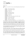
help
he
help on DINK32 commands
MDINK32 Compatible
help <command>
This provides information on the commands implemented by DINK32. Since MDINK32
only has a subset of commands, the help command displays different information.
Examples:
DIN K32 _KA HLUA >> hel p
San dpo int /MPC 824 0 D INK COM MAN D L IST
Com man d
M nem onic
=== === =
= === ====
Abo ut. ..
a bou t, a b
Ben chm ark
b enc hmar k, bm
Def ine Al ias
d efa lias , d a
Dev ice Mo dify
d evm od, dm
Dis ass emb le
d isa ssem , d s
Env iro nme nt
e nv
Fla sh upd ate
fu
Hel p
h elp , he
Inf o
i nfo , in
Mem ory Co mpar e
m emc omp, mc
Mem ory Mo dify
m emo d, m m
Mem ory In fo
m emi nfo, mi
Mem ory Se arch
m ems rch, ms
Men u
me nu, m e
PCI Sl ot Disp lay
p cid isp, pd
PCI Co nfi g Re gs
p cic onf, pc f
Reg ist er Modi fy
r egm od, rm
Res et
r ese t, r st
Set Ba ud Rate
s etb aud, sb
Sho w S PRs
s pr_ name , s x
Tau
t au
Tra ce
t rac e, t r
Com man d
M nem oni c
=== === =
= === === =
Ass emb le
a sse mbl e, a s
Bre akp oin t o ps
b kpt , b p
Dev ice Di spl ay
d evd isp , dd
Dev ice Te sts
d evt est , de v
Dow nlo ad
d own loa d, d l
Fla sh com man ds
f las h, fl
Go
go
His tor y
h ist ory ,his t
Log se ssi on
l og
Mem ory Di spl ay
m emd isp , md
Mem ory Fi ll
m emf ill , mf
Mem ory Mo ve
m emo ve, mv
Mem ory Te st
m emt est , mt
PCI B us P robe
pc ipr obe, ppr
PCI Re g M odi fy
p cim od, pm
Reg ist er Dis play
r egd isp , rd
Rea l-T ime Cl ock
t ime , r tc
Run Al ias
r una lia s, r a
Set In put
s eti npu t, s i
Sym bol ta ble
s ymt ab, st
Tra nsp are nt Mode
t ran spa r, t m
. ( rep eat la st c omm and )
For ad dit iona l d eta ils ab out a c omm and , p leas e t ype "h elp <mn emo nic >"
DIN K32 _MP C603 ev >>h elp
E xci mer DI NK C OMM AND LI ST
Exc ime r D INK COM MAN D L IST
Com man d
M nem onic
Com man d
=== === =
= === ====
=== === =
Abo ut. ..
a bou t, a b
Ass emb le
Ben chm ark
b enc hmar k, bm
Bre akp oin t o ps
Def ine Al ias
d efa lias , d a
Dis ass emb le
Dow nlo ad
d own load , d l
Fla sh com man ds
Go
go
Hel p
His tor y
h ist ory, his t
Inf o
Log se ssi on
l og
Mem ory Co mpa re
Mem ory Di spla y
m emd isp, md
Mem ory Mo dif y
Chapter 4. MDINK32/DINK32 Commands
M nem oni c
= === === =
a sse mbl e, a s
b kpt , b p
d isa sse m, d s
f las h, fl
h elp , h e
i nfo , i n
m emc omp , mc
m emo d, mm
4-37
Commands
Mem ory Fi ll
m emf ill, mf
Mem ory In fo
m emi nfo , mi
Mem ory Mo ve
m emo ve, mv
Mem ory Se arc h
m ems rch , ms
Mem ory Te st
m emt est, mt
Men u
m enu , m e
Reg ist er Disp lay
r egd isp, rd
Reg ist er Mod ify
r egm od, rm
Res et
r ese t, r st
Run Al ias
r una lia s, r a
Set Ba ud Rate
s etb aud, sb
Set In put
s eti npu t, s i
Sho w S PRs
s pr_ name , s x
Sym bol ta ble
s ymt ab, st
Tau
t au
Tra nsp are nt Mode
t ran spa r, t m
Tra ce
t rac e, t r
. ( rep eat la st c omm and )
For a ddi tio nal de tai ls ab out a c omm and, p lea se ty pe "h elp < mnem oni c>"
DIN K32 _MP C603 ev >>
MDI NK
Com man d
=== === =
Abo ut. ..
Dow nlo ad
Hel p
Go
Men u
M INI MUM DI NK C OMM AND LI ST
M nem onic
= === ====
abou t, ab
down loa d, dl
help ,he
go
menu , m e
DIN K32 _75 0 >> he lp go
Individual Commands
DIN K32 _MP C603 ev >>h elp go
GO
==
Mne mon ic: go
Syn tax : g o [< add res s>| +]
Des cri pti on: T his com man d all ows the user to e xec ute u ser cod e
sta rti ng at
the sp ecif ied ad dres s.
Exe cut ion wil l c onti nue unt il a
bre akp oin t or
a n e xcep tio n o ccu rs.
If t he " +" f orm is used , t hen exe cuti on will st art at t he a ddr ess
d efi ned by the co nten ts of bit s 0- 29 of SRR 0.
Th e us er sh oul d ter min ate t hei r cod e wi th an ille gal opc ode o r
wit h a
bre akp oint .
T he v alu e o f di nk_ loop () is i nit ial ly p lac ed i n
the Us er
P rog ramm ing Mo del lin k r egi ste r.
If you te rmin ate yo ur code
wit h a blr to tha t l ocat ion yo u wi ll re-e nte r D INK.
In th e
pro ces s,
ho wev er, y ou wi ll pe rfo rm th e pr olog of th e din k_l oop f unc tio n
whi ch
w ill sa ve reg iste rs (ex . l r) off ont o t he cur ren tly def ine d
sta ck (ie .
t he valu e i n r 1). Thi s m ay be an u nex pec ted sid e-e ffe ct.
N ote : If a bre akp oint is en cou nter ed, th e u ser mus t c lea r th e
b rea kpoi nt in ord er f or exe cut ion to con tin ue.
4-38
Dink32 R12 User’s Manual
Commands
DIN K32 _MP C603 ev >>
Chapter 4. MDINK32/DINK32 Commands
4-39
Commands
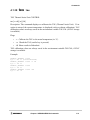
4.1.17 Identify id
Mnemonic: identify, id
Syntax: id
Description: This command shows information about the PPMC card.
The ’id’ command stores board ID in the I2C EEPROM. Of particular interest is the
L2CACHE field, which is copied on reset. This allows cache settings to be associated with
a PPMC card instead of the Sandpoint motherboard.
4-40
Dink32 R12 User’s Manual
Commands
4.1.18
log
log
Toggles logging
Only available on yellowknife and sandpoint.
•
log
This command provides the capability to log a debug session. The command toggles the
logging function. When logging is enabled, all characters sent to the terminal will be
echoed to the host port, the second com port, com2 (duart channel B) in the system. On
Yellowknife, this will be the alternate com port to the terminal port. See Section 4.1.36,
“setbaud sb".
Example:
DIN K32 _75 0 >> lo g
You ar e e nab lin g l ogg ing! A fter th is mes sag e a ll inp ut and ou tpu t t o
you r ter min al wi ll be mirr ore d out to th e hos t por t. No w wou ld b e a
tim e t o o pen an edi tor on the ho st and get in to inse rt mod e
DIN K32 _75 0 >> lo g
Log gin g d isab led !
Chapter 4. MDINK32/DINK32 Commands
4-41
Commands
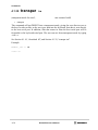
4.1.19
memcompare
mc
Compare memory
•
Syntax: mc <address> <address> <address>
Description: This command compares two blocks of memory.
Example:
mc 100 000 100 100 c 2 000 00
compares 100000 to 200000, 100004 to 200004, etc.
4-42
Dink32 R12 User’s Manual
Commands
4.1.20
memdisp
md
display memory
•
memdisp address
•
memdisp start +
•
memdisp start - end
This command displays data stored in the specified memory locations. The display will
always be aligned on a 16-byte boundary in which the address given will be included. In
order to keep from saturating the screen, a maximum of four lines of data are displayed on
the screen, followed by a prompt. To continue viewing data, the user enters <return> at the
prompt. Multiple parameters may be entered.
If the \"+\" form is used, the command will continue to display blocks of memory if the user
enters <return> at the prompts, until the end of memory is reached or until the user enters
an \"x\". If the two-address version is used, the command will display the contents of
memory between and including each address specified in the range. If more than four lines
of data are requested, the user can then enter an \"x\" at the prompt to quit before the end
of the display range.
The start address is normalized to the previous quad-word boundary. Likewise, the ending
address is normalized to the next quad-word boundary. For example, if the start address was
0x00000104 then the first memory address to be displayed would be 0x00000100. If the
end address was 0x00000104 then the last memory location to be displayed would be
0x0000010C.
Exa mpl es:
DIN K32 _75 0 >> me mdi sp 6010 0,6 020 0
0x0 006 010 0 00 000 041 00 0000 42 000 000 43 0 000 004 4
0x0 006 020 0 00 000 000 00 0000 00 000 000 00 0 000 000 0
DIN K32 _75 0
0x0 006 010 0
0x0 006 011 0
0x0 006 012 0
0x0 006 013 0
>> me mdi sp 6010 0-6 013 0
00 000 041 00 0000 42 000 000 43
00 000 045 00 0000 46 000 000 47
00 000 000 00 0000 00 000 000 00
00 000 000 00 0000 00 000 000 00
DIN K32 _75 0
0x0 006 026 0
0x0 006 027 0
0x0 006 028 0
>> me mdi sp 6026 0+
00 000 000 00 0000 00 000 000 00 0 000 000 0
00 000 000 00 0000 00 000 000 00 0 000 000 0
00 000 000 00 0000 00 000 000 00 2 400 240 0
0 000 004 4
0 000 004 8
0 000 000 0
0 000 000 0
Chapter 4. MDINK32/DINK32 Commands
4-43
Commands
4.1.21
memfill
mf
memory fill
memfill start end data
The range of memory spanning from the starting address to the ending address is filled in
with the given 32-bit data pattern. The fill is inclusive of the end point.
Examples:
DIN K32 _75 0
DIN K32 _75 0
DIN K32 _75 0
0x0 006 012 0
0x0 006 013 0
0x0 006 014 0
0x0 006 015 0
0x0 006 016 0
>> me mfi ll 6010 0 6 020 0 8 9898 989
>> me mfi ll 6014 0 6 015 c 0 0000 000
>> me mdi sp 6012 0-6 016 0
89 898 989 89 8989 89 898 989 89 8 989 898 9
89 898 989 89 8989 89 898 989 89 8 989 898 9
00 000 000 00 0000 00 000 000 00 0 000 000 0
00 000 000 00 0000 00 000 000 00 0 000 000 0
89 898 989 89 8989 89 898 989 89 8 989 898 9
DIN K32 _75 0
DIN K32 _75 0
0x0 006 012 0
0x0 006 013 0
0x0 006 014 0
0x0 006 015 0
0x0 006 016 0
>> me mfi ll 6014 4 6 014 4 4 4444 444
>> me mdi sp 6012 0-6 016 0
89 898 989 89 8989 89 898 989 89 8 989 898 9
89 898 989 89 8989 89 898 989 89 8 989 898 9
00 000 000 44 4444 44 000 000 00 0 000 000 0
00 000 000 00 0000 00 000 000 00 0 000 000 0
89 898 989 89 8989 89 898 989 89 8 989 898 9
4-44
Dink32 R12 User’s Manual
Commands
4.1.22
meminfo mi
mi [-s][-c][-c]
mi displays information about the memory settings. If no option is selected, the current
memory controller settings are decoded.
Options (for SODIMM/DIMM-based systems only):
•
•
-s
-- show I2C ROM info.
-c -- compare I2C info to memory controller settings for errors. If -c is entered
a second time, the settings will be corrected. Setting the MEMOPT ENV variable is
equivalent to entering mi -c -c at startup.
Example:
DIN K32 _AR THUR >> mi
Mem ory se ttin gs:
R OM Spe ed: 30 ns (2 cloc ks)
S DRA M B ank 0:
Di sab led
S DRA M B ank 1:
Di sab led
S DRA M B ank 2:
En abl ed
Ra nge : [0 000 000 0 - > 00 0ff fff ]
Sp eed : 0/ 1/1 /1
S DRA M B ank 3:
En abl ed
Ra nge : [0 800 000 0 - > 08 0ff fff ]
Sp eed : 0/ 1/1 /1
S DRA M B ank 4:
En abl ed
Ra nge : [0 840 000 0 - > 09 4ff fff ]
Sp eed : 0/ 1/1 /1
S DRA M B ank 5:
En abl ed
Ra nge : [0 000 000 0 - > 00 0ff fff ]
Sp eed : 0/ 1/1 /1
S DRA M B ank 6:
En abl ed
Ra nge : [0 000 000 0 - > 00 0ff fff ]
Sp eed : 0/ 1/1 /1
S DRA M B ank 7:
Di sab led
1 MB yte s
1 MB yte s
17 M Byt es
1 MB yte s
1 MB yte s
Chapter 4. MDINK32/DINK32 Commands
4-45
Commands
4.1.23
memod
mm
memory modify
•
memod address
•
memod start +
•
memod start - end
Memory modify is an interactive command. It will display the contents of the given
memory address and allow the user to change the value stored there. Memory is considered
to be a contiguous set of 32-bit integers.
The “plus” form causes the command to start at a given address and continue until the end
of memory or until the user types “x” to exit the memory modify loop.
The “range” form allows modifications for the inclusive range from start to end. When the
end address is reached the memory modify loop is automatically exited. The user can type
“x” at any time to exit the memory modify loop.
•
-b for byte
•
- h for halfword
•
-w for word (default) )
Examples:
DIN K32 _75 0 >> me mod 60 100
0x0 006 010 0 : 0x8 989 898 9 : ? 4 444 444 4
DIN K32 _75 0 >> me mod -b 601 00
0x0 006 010 0 : 0x4 444 444 4 : ? 6 6
DIN K32 _75 0 >> me mod -h 601 00
0x0 006 010 0 : 0x6 644 444 4 : ? 3 333
DIN K32 _75 0 >> me mod -w 601 00
0x0 006 010 0 : 0x3 333 444 4 : ? 2 222 222 2
DIN K32 _75 0
0x0 006 011 0
0x0 006 011 4
0x0 006 011 8
>> me mod 60 110- 601 18
: 0x8 989 898 9 : ? 1 111 111 1
: 0x8 989 898 9 : ? 2 222 222 2
: 0x8 989 898 9 : ? 3 333 333 3
DIN K32 _75 0
0x0 006 020 0
0x0 006 020 4
0x0 006 020 8
>> me mod 60 200+
: 0x8 989 898 9 : ? 1 234 123 4
: 0x0 000 000 0 : ? 1 234 123 4
: 0x0 000 000 0 : ? x
4-46
Dink32 R12 User’s Manual
Commands
4.1.24
memove
mv
memory move
•
memove <start addr> <end addrs> <dest addr>
This command copies data from a block of memory, bounded inclusively by the first two
addresses, to a block of memory starting at the third address. The result of this command
will be two identical blocks of memory. If the third address falls between the first two
addresses, an error message is returned and memory will not be modified.
Examples:
DIN K32 _75 0
DIN K32 _75 0
0x0 006 010 0
0x0 006 011 0
0x0 006 012 0
0x0 006 013 0
0x0 006 014 0
0x0 006 015 0
>> me mfi ll 6010 0 6 011 0 f ffff fff
>> me mdi sp 6010 0-6 015 0
ff fff fff ff ffff ff fff fff ff f fff fff f
ff fff fff 00 0000 00 000 000 00 0 000 000 0
00 000 000 00 0000 00 000 000 00 0 000 000 0
00 000 000 00 0000 00 000 000 00 0 000 000 0
00 000 000 00 0000 00 000 000 00 0 000 000 0
00 000 000 00 0000 00 000 000 00 0 000 000 0
DIN K32 _75 0
DIN K32 _75 0
0x0 006 010 0
0x0 006 011 0
0x0 006 012 0
0x0 006 013 0
0x0 006 014 0
0x0 006 015 0
>> me mov e 6 0100 60 110 60 140
>> me mdi sp 6010 0-6 015 0
ff fff fff ff ffff ff fff fff ff f fff fff f
ff fff fff 00 0000 00 000 000 00 0 000 000 0
00 000 000 00 0000 00 000 000 00 0 000 000 0
00 000 000 00 0000 00 000 000 00 0 000 000 0
ff fff fff ff ffff ff fff fff ff f fff fff f
ff fff fff 00 0000 00 000 000 00 0 000 000 0
Chapter 4. MDINK32/DINK32 Commands
4-47
Commands
4.1.25
memsrch
ms
memory search
ms <address> <address> <data>
This command searches for a 32-bit data pattern in the inclusive block specified by the
range of the two addresses. If the second address is less than the first address, an error
message is returned and no search is performed. If the pattern is found, the addresses of
matching data are printed to the screen. The command,
ms 50100 50200 fff01234
searches for the data pattern "fff01234" in memory locations 0x50100 to 0x50200
inclusive, and prints the matching addresses.
Example:
DIN K32 _60 3e > >md 60 100 -601 20
0x0 006 010 0
1 0ff 7f0 0 0 0fff f00 ff 202 3ff ff0 402 ff
.. ... ... .
#.. ...
0x0 006 011 0
0 0ff ff00
00f fff 00
ff 500 8ff
f f10 02f f
... ... ... P... ...
0x0 006 012 0
0 0ef ef00
00f fff 00
ff 010 0ff
f f00 30f f
... ... ... .... .0.
DIN K32 _60 3e > >ms 60 100 601 20 ff5 008 ff
0 x000 601 18
4-48
Dink32 R12 User’s Manual
Commands
4.1.26
memtest
mt
memory test
•
mt [-d dev][-b|-h|-w][-l loop][-t][-h][-a][-q] addr1-addr2
The memtest command performs various memory tests on local memory or device
registers. The basic format is:
mt [-d dev][-b|-h|-w][-l loop][-t][-h][-a][-q] addr1-addr2
•
-d device
Test the indicated device instead of memory. Use the "dm"
command to get a list of devices. NOTE: testing non-volatile I2C EEPROM devices
can destroy valuable information as well as reduce the life expectancy of those
devices.
•
-b, -h, -w
Test memory or device using byte, half-word or word accesses.
Memory can be tested in any size, while devices may be limited to bytes. If not
specified, the default size is word for memory and bytes for devices.
•
-l loop-cnt
Specifies the number of times the memory test should perform all
tests. If not specified, each test is performed once, while if '0’ is specified, the test is
run forever.
•
-x
If specified, the testing halts immediately when any error is found.
This is useful for extended passes to trap on any error.
•
-q
Perform only a quick test.
•
-a
Perform all defined memory tests (can be slow).
•
-n list
Perform only specified memory tests. Tests are selected by adding
one or more of the following letters to "list":
— -0 : walking 0's test (non-destructive, slow)
— -1 : walking 1's test (non-destructive, slow)
— -A : address=data test (destructive)
— -Q : quick pattern test (non-destructive)
— -R : random pattern test (non-destructive)
•
— -S : write sensitivity test (destructive, slow)
-t Show elapsed time (only on systems with a real-time clock).
Chapter 4. MDINK32/DINK32 Commands
4-49
Commands
•
addr1-addr2
Specifies the starting and ending address, respectively. The
addresses must be aligned to the size of the access (as specified by the-b/-h/-w
option) Note: be careful not to test memory regions used by DINK. 0x90000 is a safe
starting point for DINK 11.0.2 or earlier.
Examples:
DIN K32 _AR THUR >> mt -q 9000 0-1 fff ffc
Th is qui ckly te sts the def aul t
32M B S DRA M DI MM
on Ye llo wkn ife/ San dpo int sy ste ms.
DIN K32 _AR THUR >> mt -q 9000 0-1 fff ffc
P ASS 1:
Quic k Tes t.. ... .... ... ... ... .... ... ... ... .... ... ... ... .... ..P ASS
Com ple ted tes ts: No er rors .
DIN K32 _AR THUR >> mt -b -a -l 0 - x 9 0000 -1f fff ff
Use all d efi ned t est t o tes t 32M B of m emo ry, u sin g onl y
acc ess es.
Re pea t t he test fo rev er unle ss an err or o ccu rs.
byt e
DIN K32 _AR THUR >> mt -b -a - l 0 -x 90 000- 1ff fff
P ASS 1:
Quic k Tes t.. ... .... ... ... ... .... ... ... ... .... ... ... ... .... ..P ASS
R and om P atte rn Test ... ... ... .... ... ... ... .... ... ... ... .... ..P ASS
W alk ing 1’s Tes t... ... ... ... .... ... ... ... .... ... ... ... .... ..P ASS
W alk ing 0’s Tes t... ... ... ... .... ... ... ... .... ... ... ... .... ..P ASS
A ddr ess Marc h T est. ... ... ... .... ... ... ... .... ... ... ... .... ..P ASS
W rit e Se nsit ivi ty T est ... ... .... ... ... ... .... ... ... ... .... ..P ASS
DIN K32 _AR THUR >> mt -n S - t 9 000 0-1 ffff f
Tes t 32M B u sin g onl y t he wr ite s ensi tiv ity t est,
ela pse d t ime.
an d repo rt th e
DIN K32 _AR THUR >> mt -t -n S 90 000 -A0 000
P ASS 1:
W rit e Se nsit ivi ty T est ... ... .... ... ... ... .... ... ... ... .... ..P ASS
Com ple ted tes ts: No er rors .
Ela pse d t ime: 0: 00: 16
DIN K32 _AR THUR >>
4-50
Dink32 R12 User’s Manual
Commands
4.1.27
menu
me
show list of DINK32 commands
MDINK32 Compatible
menu (same as “help”)
This command will list all of the commands that are available in the current implementation
of DINK32.
Examples:
DIN K32 _AR THUR >> men u
E xci mer DI NK C OMM AND LI ST
Com man d
M nem onic
Com man d
=== === =
= === ====
=== === =
Abo ut. ..
a bou t, a b
Ass emb le
Ben chm ark
b enc hmar k, bm
Bre akp oin t o ps
Def ine Al ias
d efa lias , d a
Dis ass emb le
Dow nlo ad
d own load , d l
Fla sh com man ds
Go
go
Hel p
His tor y
h ist ory, his t
Inf o
Log se ssi on
l og
Mem ory Di spl ay
Mem ory Mo dify
m emo d, m m
Mem ory Fi ll
Mem ory In fo
m emi nfo, mi
Mem ory Mo ve
Mem ory Se arch
m ems rch, ms
Mem ory Te st
Men u
m enu , me
Reg ist er Dis play
Reg ist er Modi fy
r egm od, rm
Res et
Run Al ias
r una lias , r a
Set Ba ud Rat e
Set In put
s eti nput , s i
Sho w S PRs
Sym bol ta ble
s ymt ab, st
Tau
Tra nsp are nt M ode
t ran spar , t m
Tra ce
. ( rep eat las t c omm and )
M nem oni c
= === === =
a sse mbl e, a s
b kpt , b p
d isa sse m, d s
f las h, fl
h elp , h e
i nfo , i n
m emd isp , md
m emf ill , mf
m emo ve, mv
m emt est , mt
r egd isp , rd
r ese t, rst
s etb aud , sb
s pr_ nam e, s x
t au
t rac e, tr
For a ddi tio nal de tai ls ab out a c omm and, p lea se ty pe "h elp < mnem oni c>"
MDI NK3 2_A RTHU R > >me nu
M INI MUM DI NK C OMM AND LI ST
Com man d
M nem onic
=== === =
= === ====
Abo ut. ..
a bou t, a b
Dow nlo ad
d own load , d l
Fla sh ram to rom
fw
-e
Fla sh dis play
f l - dsi
Hel p
h elp ,he
Go
go
Men u
m enu , me
For a ddi tio nal de tai ls ab out a c omm and, p lea se ty pe "h elp < mnem oni c>"
Chapter 4. MDINK32/DINK32 Commands
4-51
Commands
4.1.28
pciconf
pcf
pci probe command (on systems with a PCI bus)
pciconf <devNum>
This command displays 26 common PCI configuration registers, and 16 additional device
specific registers of a PCI device. The devNum depends on which PCI slot the device is
attached to, and it can be found by executing the ppr (PCI Device Probe) command.
Example:
DIN K32 _75 0 >> pp r
dev No
PC I A DR.
=== ==
== === ===
11
0x 800 058 00
DIN K32 _75 0 >>
ADD R.
=== ==
0x0 0
0x0 2
0x0 4
0x0 6
0x0 8
0x0 9
0x0 a
0x0 b
0x0 c
0x0 d
0x0 e
0x0 f
0x1 0
0x1 4
0x1 8
0x1 c
0x2 0
0x2 4
0x2 8
0x2 c
0x2 e
0x3 0
0x3 c
0x3 d
0x3 e
Typ e < ret urn>
4-52
DEVI CE ID
VE NDOR ID
==== === == === ==== ==
0x05 65
0x 10ad
pc f 1 1
VA LUE
DESC RIP TIO N
== ===
==== === === =
0x 10a d
Vend or ID
0x 056 5
Devi ce ID
0x 000 7
PCI com man d
0x 020 0
PCI sta tus
0x 04
Revi sio n I D
0x 00
Stan dar d P rog ramm ing In ter face
0x 01
Subc las s c ode
0x 06
Clas s c ode
0x 00
Cach e l ine si ze
0x 00
Late ncy ti mer
0x 80
Head er typ e
0x 00
BIST co ntr ol
0x 000 000 00
Base Ad dre ss Regi ste r 0
0x 000 000 00
Base Ad dre ss Regi ste r 1
0x 000 000 00
Base Ad dre ss Regi ste r 2
0x 000 000 00
Base Ad dre ss Regi ste r 3
0x 000 000 00
Base Ad dre ss Regi ste r 4
0x 000 000 00
Base Ad dre ss Regi ste r 5
0x 000 000 00
Card bus CI S P oint er
0x 000 0
Subs yst em Ven dor ID
0x 000 0
Subs yst em ID
0x 000 000 00
Expa nsi on ROM Bas e A ddr ess
0x 00 Int err upt lin e
0x 00 Int err upt pin
0x 00 MIN _GN T
to co nti nue or "x" to qui t > >
Dink32 R12 User’s Manual
Commands
4.1.29
pcidisp
pd
pci display (on systems with a PCI bus)
pcidisp <devNum> <regNum>
This command reads a configuration register (regNum) of a PCI device (devNum). The
devNum depends on the PCI slot the device )is attached, and it can be found by executing
the ppr (PCI Device Probe) command..
Example:
DIN K32 _75 0 >> pc idi sp 11 1 0
0x1 0 0 x12 3456 78 Bas e A ddre ss Reg ist er 0
Chapter 4. MDINK32/DINK32 Commands
4-53
Commands
4.1.30
pcimod
pm
pci modify (on systems with a PCI bus)
pcimod <devNum> <regNum>
This command is used to modify the content of a configuration register (regNum) of a PCI
device (devNum). The DevNum depends on the PCI slot the device is attached to, and it
can be found by executing the ppr (PCI Device Probe) command. This command first
displays the current value of the desired register, then asks the user to enter the new value.
This command does not return an error if the register requested is a read-only register.
Example:
DIN K32 _75 0 >> pc imo d 1 1 10
0x1 0 0 x00 0000 00 Bas e A ddre ss Reg ist er 0
New Va lue ? 12 345 678
DIN K32 _75 0 >> pc idi sp 11 1 0
0x1 0 0 x12 3456 78 Bas e A ddre ss Reg ist er 0
4-54
Dink32 R12 User’s Manual
Commands
4.1.31
pciprobe
ppr
pci probe command (on systems with a PCI bus; non-excimer build)
pciprobe
This command scans all legal PCI device numbers (from 10 to 31) and detects whether any
device is attached to them. If a PCI device is found, the following information is displayed:
Device number, PCI address, Device Id and Vendor Id.
Example:
DIN K32 _75 0 >> pc ipr obe
Dev # P CI ADD R
DE VIC E I D
VEND OR ID
CL ASS
=== == === ==== === == === ==== == === === = == === === === ==== ==
11
0 x80 005 800
0x 056 5
0x10 ad
Br idge In ter face
12
0 x80 006 000
( can not pr obe sel f)
15
0 x80 007 800
0x 200 0
0x10 22
Ne twor k I nte rfac e
Chapter 4. MDINK32/DINK32 Commands
4-55
Commands
4.1.32
regdisp
rd
display registers
Syntax:
rd[-v][-e][r|rx|rx+|rx-ry|f|fx|fx+|fx-fy|sx|spr_name|northbridge|nb|mpc106|mpc107|mpc82
40]
•
regdisp r - entire general register family
•
regdisp rx - one general purpose register
•
regdisp rx+ - from rx to r31
•
regdisp rx-ry - from rx to ry
•
regdisp f - entire floating point family
•
regdisp fx - one floating point register
•
regdisp fx+ - from fx to f31
•
regdisp fx-fy - from fx to fy
•
regdisp SPR by name- view spr by name, such as hid0, contents.
•
regdisp sx - one special purpose register
•
regdisp vx - one altivec vector register
•
regdisp v+ - all altivec vector registers
•
regdisp -v - verbose display, only valid if env -c, env rdmode=e is set.
This will display the contents of the specified registers. This command offers the user
several options for viewing the registers. The whole family of general purpose registers or
floating point registers can be viewed by typing “regdisp r” or “regdisp f” respectively. A
single register can be viewed by specifying rx, fx, or sx, where the first character denotes
the register family and the second character denotes the register number. Special purpose
registers may be selected by their standard abbreviations as well as their register number.
The “plus” form displays the contents of the register family starting with the given register
up to and including the last register in that family. The “range” form displays the contents
of the registers from rx to ry or from fx to fy.
Note that the “entire family”, “plus”, and “range” forms are not available in the special
purpose register family. This is due to the architectural design feature in which the special
purpose registers all have unique register numbers and are not numbered sequentially.
The above parameter forms can be combined by separating them with a comma or white
space. This will display multiple registers in different register families with one command.
Note that the register display is aligned on an even-numbered register boundary, so if an
even numbered register needs to be displayed, the odd-numbered register following it is
4-56
Dink32 R12 User’s Manual
Commands
also displayed.
Most of the SPRs can suppress the verbose mode. This is still the default for compatibility
purposes. If suppressed you can get verbose mode by with the following commands,
rd -v and you can do rd -e to get the fields explained (where possible). Not all SPRs
are quietened, just the most interesting ones. The 601 registers are not suppressed. To
enable quiet mode use these commands: env -c, env rdmode=e, see Section 4.1.11,
“env env".
Verbosity is suppressed for:
•
XER
SDR1
CR
IABR
PMC4 LR
SRR0
•
CTR
SRR1 MSR
•
DAR
EAR
HID1
•
L2CR
USIA
HASH1 HID1
•
UPMC2 UMMCR1 HASH2 SDA
DBATxL
•
UPMC3 UMMCR0 IMISS DABR
TBU
•
UPMC4 DMISS ICMP
•
UPMC1 DCMP
•
MSSCR1 UBAMR PIR
•
VRSAVE VSCR
FPSCR MMCR0 SIA
PMC1 THRM2 DSISR SPRGx SRx
MMCR1 THRM1 DEC
RPA
PVR
PMC2 THRM3
PMC3
ICTC
DBATxU
IBATxU TBL
IBATxL MSSCR0
UMMCR2
MMCR2 BAMR
Field descriptions are interpreted for:
•
DBATxU DBATxL SRx
PVR IBATxU IBATxL HID1
L2CR
•
CR FPSCR MSR IABR THRM1 THRM2 THRM3 L2CR DABR MPC10x:
PICR1/A8 and PICR2/AC
Examples:
DIN K32 _75 0 >> re gdi sp r1-r 2,f 4-f 6,h id0
gpr 00: 0x 0000 000 0 g pr0 1: 0 x00 060 000
gpr 02: 0x 0000 000 0 g pr0 3: 0 x00 006 8ac
fpr 04: 0x 0000 000 000 000 000 fpr 05: 0x 0000 000 000 000 000
fpr 06: 0x 0000 000 000 000 000 fpr 07: 0x 0000 000 000 000 000
DIN K32 _75 0> r egd isp hi d0
Har dwa re Impl eme nta tio n De pen den t 0
--- --- --- ---- --- --- --- ---- --- --- --- ---- --- --- --- ---- --- --- --- -hid 0 : 0x 8001 008 0
100 000 000 0000 001 000 000 0010 000 000
Chapter 4. MDINK32/DINK32 Commands
4-57
Commands
+.. ... ... .... ... ... ... .... ... ... == = ma ste r c hec ksto p e nab le
+.. ... ... .... ... ... ... .... ... .. === mi cro cod e s elf test ch eck sto p
lat ch
+.. ... ... .... ... ... ... .... ... . == = ch ecks top fol low ing a mac hin e
che ck
+.. ... ... .... ... ... ... .... ... == = m ulti -si de hit in the tl b
+.. ... ... .... ... ... ... .... .. === mu lti- sid e h it in c ach e d ire ctor y
+.. ... ... .... ... ... ... .... . = == seq uenc er han g
+.. ... ... .... ... ... ... .... == = d isp atch ti me- out
+.. ... ... .... ... ... ... ... === bu s a ddre ss par ity err or
+.. ... ... .... ... ... ... .. = == bus da ta p ari ty err or
+.. ... ... .... ... ... ... . == = c ach e p arit y e rro r
+.. ... ... .... ... ... ... === in val id micr oco de ins truc tio n
+.. ... ... .... ... ... .. === pio bu s p roto col er ror
+++ ... ... .... ... ... . = == r ese rve d
+++ +++ +++ ++++ ++. . = == chec kst op ena bles
+. === er ror in mai n c ache (i n a rra y in it)
+ = == res erve d
DIN K32 _75 0 >> re gdi sp r1 f 2 r 3 f 4 r 8 s5
gpr 00: 0x 0000 000 0 g pr0 1: 0 x00 060 000
fpr 02: 0x 0000 000 000 000 000 fpr 03: 0x 0200 fee d01 0ca b00
gpr 02: 0x 0000 000 0 g pr0 3: 0 x00 006 8ac
fpr 04: 0x 0000 000 000 000 000 fpr 05: 0x 0000 000 000 000 000
gpr 08: 0x 0000 000 0 g pr0 9: 0 x00 000 000
DIN K32 _75 0 >> re gdi sp r23+
gpr 22: 0x 2cab 4da d g pr2 3: 0 x00 000 000
gpr 24: 0x 0000 000 0 g pr2 5: 0 x00 000 000
gpr 26: 0x 0000 000 0 g pr2 7: 0 x00 700 007
gpr 28: 0x 0000 000 0 g pr2 9: 0 x00 000 000
gpr 30: 0x 00fa ce0 0 g pr3 1: 0 x00 000 000
DIN K32 _MA X >> rd v2
vr
2:
0 x000 000 00
0 0000 000
000 0000 0
00 abc def
DIN K32 _MA X >> rm v2
vr
2:
0 x000 000 00
0 0000 000
000 0000 0
00 abc def
DIN K32 _MA X >> rd v2
vr
2:
0 x000 000 00
0 0000 000
000 0000 0
12 345 678
f ffff fff
f ffff fff
0 0000 000
fff ffff f
fff ffff f
001 2345 6
ff fff fff
ff fff fff
78 abc def
f ffff fff
f ffff fff
1 2345 678
fff ffff f
fff ffff f
abc def0 0
ff fff fff
ff fff fff
87 654 321
DIN K32 _MA X >> rd v
vr
0:
0 xfff fff ff
vr
1:
0 xfff fff ff
vr
2:
0 x000 000 00
...
vr 29:
0 xfff fff ff
vr 30:
0 xfff fff ff
vr 31:
0 x000 000 00
: ? 123 4567 8
This example contrasts the verbose mode versus the non verbose mode of display. See the
command env.
4-58
Dink32 R12 User’s Manual
Commands
DIN K32 _AR THUR >> rd msr
MSR : 0x0 0003 930
P OW= 0
EE=0
P R=0
F P=1
ME =1
B E=0
F E1=1
I P=0
I R=1
DR =1
T LB/ GPR =0
V MX= 0
PM=0
FE 0=1
SE =0
RI =0
LE= 0
DIN K32 _AR THUR >> rd -v msr
Mac hin e S tate Re gis ter
--- --- --- ---- --- --- --- ---- --- --- --- ---- --- --- --- ---- --- --- --- ---- --- --MSR : 0x0 0003 930
000 000 000 0000 000 001 110 0100 110 000
+++ +++ +++ ++++ ... ... ... .... ... ... == = re ser ved
+.. ... ... .... ... ... == = ac tiv ate s p ower ma nag eme nt
+. ... ... .... ... ... == = tl b g pr ove rlay en abl e
+ ... ... .... ... ... == = re ser ved
+.. ... .... ... ... == = ex ter nal in terr upt en abl e
+. ... .... ... ... == = pr ivi leg e l evel
+ ... .... ... ... == = fl oat ing -po int ava ila ble
+.. .... ... ... == = ma chi ne che ck e nab le
+.. ... ... ... === fl oat ing poi nt e xce pti on p oin t 0
+ .... ... ... == = si ngl e-s tep tra ce ena ble
+... ... ... == = re ser ved
+.. .... .. == = flo ati ng po int e xce pti on po int 1
+. ... ... == = re ser ved
+ ... ... == = ex cep tio n p refi x
+ ... .. == = in stru cti on ad dre ss t rans lat ion
+. ... == = da ta add res s tr ans lat ion
+ ... == = re ser ved
+ .. = == perf orm anc e mo nit or m ark ed m ode
+. === RESE T or MC e xce pti on r ecov era ble
+ == = li ttl e e ndi an m ode en abl e
DIN K32 _AR THUR >>
Chapter 4. MDINK32/DINK32 Commands
4-59
Commands
4.1.33
regmod
rm
modify registers
Syntax:
rm[-v][-e][r|rx|rx+|rx-ry|f|fx|fx+|fx-fy|sx|spr_name|northbridge|nb|mpc106|mpc107|mpc82
40]
•
regmod r - entire general register family
•
regmod rx - one general purpose register
•
regmod rx+ - from rx to r31
•
regmod rx-ry - from rx to ry
•
regmod f - entire floating point family
•
regmod fx - one floating point register
•
regmod fx+ - from fx to f31
•
regmod fx-fy - from fx to fy
•
regmod SPR by name- view spr by name, such as hid0, contents.
•
regmod sx - one special purpose register
•
regmod vx - one altivec vector register
•
regmod v+ - all altivec vector registers
•
regmod -v - verbose display, only valid if env -c, env rdmode=e is set.
This command modifies the contents of the specified registers. r, f will access the entire
general purpose or floating point family; rx, fx, sx, or spr_name will access the specified
register. Multiple parameters may be entered. The user can enter <return> to leave data
unmodified, or an \"x\" to quit. If the \"+\" form is used, the command will display one
register at a time and prompt the user for a new value. It will continue to do this for the
entire family starting with the specified register. If the two-address version is used, the
command will display one register at a time and prompt the user for a new value. It will do
this for all the registers specified in the range.
Note that special purpose, and mpc106 registers can only be accessed individually and not
as a family or with the \"+\" or range forms. mpc106 supports -b, -h, -w options for byte,
halfword, and word access.
Most of the SPR’s can suppress the verbose mode, see Section 4.1.32, “regdisp rd".
Examples:
DIN K32 _60 3e > >rm r6
gpr 06 = 0 x000 000 00 : ? 123 456 78
4-60
Dink32 R12 User’s Manual
Commands
DIN K32 _60 3e > >rd r6
gpr 06: 0x 1234 567 8 g pr0 7: 0 x00 000 000
DIN K32 _60 3e
ADD R. VAL UE
=== == === ==
0x7 0 0 x00 00
new va lue ?
> >rm mp c10 6 70
D ESC RIP TIO N
= === === === =
P owe r m ana geme nt con fig . 1
1 234
DIN K32 _60 3e
ADD R. VAL UE
=== == === ==
0x7 0 0 x12 34
> >rd mp c10 6 70
D ESC RIP TIO N
= === === === =
P owe r m ana geme nt con fig . 1
DIN K32 _60 3e > > r m f 4-f 7, s 8
"di spl ays t he con ten ts of fl oat ing p oin t regi ste r 4 and pr omp ts th e
use r f or ne w d ata , t hen in cre men ts thr ough r egi ster s 5-7. T hen th e
con ten ts of s 8 a re dis play ed and ca n be mo dif ied .”
DIN K32 _60 3e > > r m m pc1 06 - h 0 xaa
" se ts t he c ont ents of t he m pc1 06 r egis ter in h alf wor d sta rti ng a t
off set 0x aa.”
Chapter 4. MDINK32/DINK32 Commands
4-61
Commands
4.1.34
rtc
rtc
modify/display real time clock <yellowknife and sandpoint only>
rtc [-s][-w]
The rtc command allows setting or displaying the real-time clock available on the
Yellowknife or Sandpoint systems.
•
-s
Sets the clock; you are prompted for the date and time.
•
-w
Watches the clock. The date and time are repeated until a key is pressed
on the keyboard.
If no option is given, the current date and time are displayed.
Example:
DIN K32 _KA HLUA >> rtc
200 0/0 0/1 4 03 :38 :14
DIN K32 _KA HLUA >> rtc -s
Yea r
: 99
Mon th
: 06
Day
: 21
Hou r
: 11
Min ute : 48
Sec ond : 00
Set to : 1 999/ 06/ 21 11: 48:0 0
199 9/0 6/2 1 11 :48 :00
DIN K32 _KA HLUA >>
4-62
Dink32 R12 User’s Manual
Commands
4.1.35
runalias
ra
run alias
runalias
This instruction will read in the string which the user has defined as an alias. Then, the
commands in this string will be executed sequentially. Also see the da and env commands.
Example:
DIN K32 _75 0 >> ru nal ias
The ru nal ias co mma nd can al so be emb edde d w ith in a c omm and li ne. Fo r
exa mpl e, if t he ali as stri ng has pr evio usl y b een def ine d a s
tr +; rd r
Typ ing th e co mma nd:
DIN K32 _75 0 >> lo g; tra ce 2 100 ; r una lias ; l og
is ide nti cal to typ ing
DIN K32 _75 0 >> lo g; tra ce 2 100 ; t r + ; rd r; lo g
See de fal ias for a com plet e e xam ple .
Chapter 4. MDINK32/DINK32 Commands
4-63
Commands
4.1.36
setbaud
sb
displays or changes the speed of the serial port
•
setbaud [ -h | -k ]
•
setbaud [ -h | –k ] rate
<mdink32 compatible>
This command sets the baud rate for the host serial port (-h) or the keyboard serial port (-k)
by
specifying
the
appropriate
flag
followed
by
a
valid
rate
(2400,4800,9600,19200,38400,57600). If only a flag is specified, the current baud rate for
that serial port is returned.
•
Example: "sb -h" would return the current baud rate for the host serial port.
•
Example: "sb -k 9600" would set the host serial port baud rate to 9600.
4.1.36.1 Host versus Keyboard.
Used by log, sb,dl, and tr commands. See Section 4.1.10, “download dl",
Section 4.1.18, “log log", and Section 4.1.39, “transpar tm".
•
The keyboard serial port (-k) indicates serial port com1, which is used for normal
communication between the terminal emulator and the evaluation board. Thus sb
-k and dl -k indicate to use the current serial port. Thus for, dl -k, use the
terminal emulator, transfer send text file, feature on the terminal
emulator connected to com1.
•
The host serial port (-h) indicates serial port com2, which is not normally used. One
can connect another terminal emulator to this serial port and with the dl -h command,
download a file. This port is only available with the Sandpoint and Yellowknife
platforms.
NOTES:
•
The maximum baud rate on the Yellowknife and Sandpoint platform is 38400.
•
The Excimer and Maximer platform will not return the current baud rate correctly.
•
The default baud rate on all platforms is 9600.
Examples:
MDI NK3 2_6 03e >> s etb aud -k 576 00
Ba ud rat e ch ang ing to 576 00. ..B Ø
<NO TE: us er mu st the n
cor res pon d to 57 600 >
4-64
c han ge
the
b aud
ra te
Dink32 R12 User’s Manual
on
the
t erm inal
to
Commands
MDI NK3 2_6 03e >>
Chapter 4. MDINK32/DINK32 Commands
4-65
Commands
4.1.37
symtab
st
displays DINK32 symbol table information
•
symtab -c
•
symtab -d
This command shows selected DINK symbols and user defined symbols and their
associated addresses. User symbols can be defined by the as command. The -c option is to
clear all user symbols. The -d option is to delete a single user symbol. The user cannot
delete or clear DINK's symbols. The symbols in the table can be used as the address
(@symbol) of the branch instruction while executing the as command.
Examples:
DIN K32 _60 3e > >as 60 000 +
0x0 006 000 0 0xf f00 00e f fs el.
f 24, f00, f00 , f0 3
r1, r2, r3
0x0 006 000 0 0x ff0 000 ef BRAN CH LAB EL br1:
0x0 006 000 0 0xff 000 0ef f sel .
f2 4, f0 0, f00 , f03
0x0 006 000 4 0xf fc0 37f c fnm sub
f30, f00 , f3 1, f0 6
r1, r5, r6
0x0 006 000 4 0x ffc 037 fc BRAN CH LAB EL br2:
0x0 006 000 4 0x ffc 037 fc fnms ub
f 30, f00 , f 31, f06
br1 :xo r
x or r3 ,r4 ,r5
br2 :xo r
x
VER IFY ING BRA NCH LA BEL S... ..
DON E V ERI FYIN G B RAN CH LABE LS!
DIN K32 _60 3e > >ds 60 000
0x0 006 000 0 0x 7c8 32a 78 BRAN CH LAB EL br1:
0x0 006 000 0 0x 7c8 32a 78 xor
r 03, r04 , r 05
DIN K32 _60 3e > >as 60 100
0x0 006 010 0 0x8 5ff ffc 4 lw zu
r1 5, 0 xff c4( r31 )
r5, r6, r7
0x0 006 010 0 0x 85f fff c4 BRAN CH LAB EL br3:
0x0 006 010 0 0x 85f fff c4 lwzu
r 15, 0xf fc4 ( r 31 )
VER IFY ING BRA NCH LA BEL S... ..
DON E V ERI FYIN G B RAN CH LABE LS!
DIN K32 _60 3e > >st
Cur ren t l ist of DIN K b ranc h l abe ls:
KEYB OAR D:
0x0
get_ cha r:
0x1e 5e4
wr ite_ cha r:
0x5f ac
T Base Ini t:
0x39 c4
TBa seR eadL owe r:
0x39 e8
TBa seR eadU ppe r:
0x3a 04
C ach eInh ibi t:
0x3a 20
In vEn L1Dc ach e:
0x3a 40
Dis L1Dc ach e:
0x3a 88
4-66
Dink32 R12 User’s Manual
br3 :xo r
x
Commands
In vEn L1Ic ach e:
Dis L1Ic ach e:
B urst Mod e:
RamI nCB k:
Ra mInW Thr u:
d ink_ loo p:
din k_pr int f:
0x3a ac
0x3b 00
0x3b fc
0x3c 3c
0x3c 7c
0x56 60
0x63 68
Cur ren t l ist of USE R b ranc h l abe ls:
br 1:
0x60 000
br 2:
0x60 004
br 3:
0x60 100
DIN K32 _60 3e > >st -d br 2
DIN K32 _60 3e > >st
Cur ren t l ist of DIN K b ranc h l abe ls:
KEYB OAR D:
0x0
get_ cha r:
0x1e 5e4
wr ite_ cha r:
0x5f ac
T Base Ini t:
0x39 c4
TBa seR eadL owe r:
0x39 e8
TBa seR eadU ppe r:
0x3a 04
C ach eInh ibi t:
0x3a 20
In vEn L1Dc ach e:
0x3a 40
Dis L1Dc ach e:
0x3a 88
In vEn L1Ic ach e:
0x3a ac
Dis L1Ic ach e:
0x3b 00
B urst Mod e:
0x3b fc
RamI nCB k:
0x3c 3c
Ra mInW Thr u:
0x3c 7c
d ink_ loo p:
0x56 60
din k_pr int f:
0x63 68
Cur ren t l ist of USE R b ranc h l abe ls:
br 1:
0x60 000
br 3:
0x60 100
DIN K32 _60 3e > >st -c
DIN K32 _60 3e > >st
Cur ren t l ist of DIN K b ranc h l abe ls:
KEYB OAR D:
0x0
get_ cha r:
0x1e 5e4
wr ite_ cha r:
0x5f ac
T Base Ini t:
0x39 c4
TBa seR eadL owe r:
0x39 e8
TBa seR eadU ppe r:
0x3a 04
C ach eInh ibi t:
0x3a 20
In vEn L1Dc ach e:
0x3a 40
Dis L1Dc ach e:
0x3a 88
In vEn L1Ic ach e:
0x3a ac
Dis L1Ic ach e:
0x3b 00
B urst Mod e:
0x3b fc
RamI nCB k:
0x3c 3c
Ra mInW Thr u:
0x3c 7c
d ink_ loo p:
0x56 60
din k_pr int f:
0x63 68
Chapter 4. MDINK32/DINK32 Commands
4-67
Commands
Cur ren t l ist of USE R b ranc h l abe ls:
DIN K32 _60 3e > >
4-68
Dink32 R12 User’s Manual
Commands
4.1.38
tau
tau
TAU Thermal Assist Unit CONTROL
tau [-c cal][-w][-fh]
Description: This command displays or calibrates the TAU (Thermal Assist Unit). If no
option is entered, the current temperature is displayed (with or without calibration). TAU
calibration values are always saved in the environment variable TAUCAL (if ENV storage
is available).
Flags:
•
-c Calibrate the TAU to the actual temperature (in ^C).
•
-w Watch the TAU (until a key is pressed)
•
-fh Show results in Fahrenheit.
TAU calibration values are always saved in the environment variable TAUCAL, if ENV
storage is available.
Example:
DIN K32 _AR THUR >> tau
Tjc = 58 ^C ( unc ali bra ted)
DIN K32 _AR THUR >> tau -c 18
Tjc = 18 ^C
DIN K32 _AR THUR >> tau
Tjc = 18 ^C
DIN K32 _AR THUR >> tau -f h
Tjc = 32 ^F
Chapter 4. MDINK32/DINK32 Commands
4-69
Commands
4.1.39
transpar
(transparent mode for com2;
•
tm
non-excimer build)
transpar
This command will put DINK32 into a transparent mode, giving the user direct access to
the host. In other words, as the user types data into the keyboard, that data is sent directly
to the host serial port. In addition, data that comes in from the host serial port will be
forwarded to the keyboard serial port. The user can exit from transparent mode by typing
<ctrl>-a.
See Section 4.1.10, “download dl", and Section 4.1.39, “transpar tm"
Example:
DIN K32 _75 0 >> tm
<cn tr- a>
4-70
Dink32 R12 User’s Manual
Commands
4.1.40
trace
tr
single step trace
•
trace address
•
trace +
This allows the user to single-step through a user program. The microprocessor will execute
a single instruction, and then return control back to the firmware. If a specific address is
given, then a single instruction is executed from that address. However, if the “plus” form
is used, then the address of the instruction to execute is derived from bits 0-29 of the SRR0
(Machine Status Save / Restore) register. After the instruction has been executed, control
is returned to the firmware (DINK32) and the user can examine the programming model or
continue to trace through instructions.
Example:
DINK32_750 >> ds 2100
0x00002100 0x7c0802a6 mfspr r00, s0008
DINK32_750 >> trace 2100
A Run Mode or Trace exception has occurred.
Current instruction Pointer: 0x00002104 stw r13, 0xfff8(r01)
DINK32_750 >> trace +
A Run Mode or Trace exception has occurred.
Current instruction Pointer: 0x00002108 add r03, r00, r01
DINK32_750 >> .
A Run Mode or Trace exception has occurred.
Current instruction Pointer: 0x0000210c mfspr r04, s0274
Chapter 4. MDINK32/DINK32 Commands
4-71
Commands
Chapter 5 DINK32 Command Form
Summary
1. .(period) . - repeat last command
2. about about - displays version information
3. assemble as - address- assemble at one address
4. bkpt bp - set, delete, list breakpoints
5. defalias da - command list - define alias for listed commands
6. devdisp dd list - display contents of device registers
7. devmod dm list - modify device data in device registers.
8. devtest dev list - perform an I/O test on Kahlua
9. disassem ds - address - disassemble at one address
10. download dl - download S-Record file to board RAM or flash
11. env env - Environment controls
12. flash fl - flash commands
13. fupdate fu - copy PCI boot rom to local PPMC
14. fw fw -e - erase all of Flash memory and load RAM to ROM (mdink32)
15. go go - address - execute from given address
16. help he - command - show more information on command
17. log log - record debug session to host
18. memdisp md - address - display memory at one address
19. memfill mf - start, end, data - fill memory block with data pattern
20. meminfo mi - displays information about the memory settings
21. memod mm address - modify memory at one address
22. memove mv - start, end, dest - move memory block to destination
23. memsrch ms - start, end, data - search memory block for data
24. memtest mt - perform various memory tests on local memory or device registers.
25. menu me - show list of available commands
26. pciconf pcf - display all config registers of a PCI device
27. pcidisp pd - display contents of a PCI config register
28. pcimod pm - modifies PCI device config register data
29. pciprobe ppr - scans for PCI devices
30. regdisp rd - display entire general register family
5-72
Dink32 R12 User’s Manual
Commands
31. regmod rm - modify entire general register family
32. rtc rtc - set and/or display the real time clock
33. runalias ra - execute the commands in the alias
34. setbaud sb - display or change the serial port baud rate
35. symtab st - displays DINK32 symbol table
36. tau tau display temperature from the Thermal Assist Unix
37. transpar tm - transparent mode Yellowknife only
38. trace tr -address trace from given address
Chapter 5. DINK32 Command Form Summary
5-73
S-Record Compression/Decompression
Chapter 6 Utilities
6.1 S-Record Compression/Decompression
6.1.1 Overview
To assist in the compression of S-Record files, a conversion utility is included with the
source code for DINK32. The dcomp utility is written in portable ANSI-compliant C,
which is easily compiled under UNIX or a PC. The dcomp utility performs both
compression and decompression of S-records. It is provided so that the user may compress
their S-record before downloading them to the board. They will automatically detected as
compressed S-records by DINK and decompressed before being written to the proper
memory locations.
6.1.2 Building
6.1.2.1 Files
The dcomp package consists of two c files, dc_tb.c, dc_unix.c and three header files, dink.h,
errors.h, and sublib.h. However, these header files call other header files, so dcomp must
be built in the dink32 source directory.
6.1.2.2 Modification of header file
The dink.h file uses the #define macro ON_BOARD, which is set by config.h. Since dcomp
must be built with ON_BOARD undefined, it is necessary to modify the config.h file.
Ensure that you return config.h to it’s released form before trying to build dink32 or
mdink32. At about line 84 of the config.h file, you will find the line, #define
ON_BOARD. Comment out this line. After the change this code will be:
/* For trying to build a version that runs under Unix,
comment out the #define for ON_BOARD. */
/* #define ON_BOARD */
6.1.2.3 Build command
Use any available c compiler, such as UNIX cc, or gcc, or Metaware, or PC compiler, cl
(Microsoft c compiler). This description uses the generic CC for the compiler invocation.
CC dc_unix.c dc_tb.c -o dcomp
This command will build the executable dcomp. Dcomp will run on the machine on which
it is built. It does not run on the Excimer and Maximer or Yellowknife and Sandpoint board.
6-74
Dink32 R12 User’s Manual
bat_decoder
6.1.3 Command syntax
Usa ge:
d comp -o pti ons <in put _fi le >out put _fi le.
Opt ion s:
- c Co mpr ess an SRe cor d f ile .
-e E xpa nd a pre vio usl y com pre ssed f ile i nto a n
Exa mpl es:
d comp -c <a .ou t.mx >a .ou t.c mp
d comp -e <a .ou t.cm p > a.o ut. mx
SR eco rd fi le.
Not e tha t thi s pr ogra m use s st din a nd st dou t, so t he < s ymbo l an d >
sym bol ar e re qui red .
exa mpl e:
Uni x $
d comp -c <d ink 32.s rc >c_ din k32. src
Thi s c omm and wi ll com pre ss the fi le din k32 .sr c
com pre sse d fi le c_d ink 32.s rc.
a nd
cre ate
th e
Uni x $
d comp -e <c _di nk32 .sr c > e_d ink3 2.s rc
Thi s co mma nd w ill d eco mpr ess (exp and )
th e fi le c _di nk32 .sr c
cre ate th e de com pre sse d (i .e. ex pan ded) fi le e_d ink3 2.s rc.
an d
e_d ink 32. src is equ iva lent to th e o rigi nal di nk3 2.sr c f ile .
UNI X $
ls -l c_d ink 32.s rc e_d ink 32.s rc din k32 .src
-rw -r- --- - 1 ma uri e
3 611 89 Jan 22 09: 43 c_d ink3 2.s rc
-rw -r- --- - 1 ma uri e
5 971 81 Jan 22 09: 41 din k32. src
-rw -r- --- - 1 ma uri e
5 971 81 Jan 22 10: 41 e_d ink3 2.s rc
6.2 bat_decoder
6.2.1 Overview
The bat_decoder program will decode BATU and BATL hex values supplied in hex. The
value of the bats will be displayed and described. The file bat_decoder.c, bat.in, and
makefile are found in the dink32/demos/utilities bat_l2_decoder.
6.2.2 Building
6.2.2.1 Using unix commands
To compile and link the program use this command. This description uses the generic CC
for the compiler invocation.:
CC bat_decoder.c -o bat_decoder.elf
Chapter 6. Utilities
6-75
bat_decoder
6.2.2.2 Using makefile supplied
Alternatively one can just call the makefile in this directory, which has seven targets.
•
start - default - displays instructions
•
all - makes bat_decoder and l2_decoder
•
bat_decoder - makes the bat_decoder.elf executable
•
cleanbat - clean just the bat_decoder files
•
l2_decoder - makes the l2_decoder.elf executable
•
cleanl2- clean just the l2_decoder files
•
clean - cleans all the files
6.2.3 Command syntax
Usa ge:
bat_decoder.elf < inputfile > outputfile
Exa mpl es:
bat _de cod er.e lf < b at. in > ba t.o ut
Not e tha t thi s pr ogra m use s st din a nd st dou t, so t he < s ymbo l an d >
sym bol ar e re qui red .
exa mpl e:
Input description:
<an integer> How many bat pairs per line are supplied?
<some_description>: <batlower_value> <batupper_value>
where:
<some_description> has no spaces or tabs (use underscore to connect names), must be
19 characters or less. The character array has only 20 characters. For bigger descriptions
this line can be changed.
<batlower_value> is a hex value
<batupper_value> is a hex value
As an example, if you wanted to decode two pairs of bats:
2
6-76
Dink32 R12 User’s Manual
bat_decoder
iba t0: 10 0000 01 100 00f ff
dba t0: 10 0000 1a 100 00f ff
If you want a description line you can use batlower=batupper=0 as in:
3
Thi s_i s_a _tes t 0 0
iba t0: 10 0000 01 100 00f ff
dba t0: 10 0000 1a 100 00f ff
The output is:
Bat De cod er - en ter th e ba t v alu es and dis pla y t he m ean ing
IB AT and DBA T h ave sam e m ean ing
Fo rma t:
des cri pti on: upp erb at_ valu e l owe rba t_va lue
Ho w m any bat en try pai rs, on e p air per li ne
Ple ase en ter the Lo wer
an d U ppe r b at v alu e i n h ex
Thi s_i s_a _tes t: Dec odi ng t he bat
Bot h b ats are ze ro, Di sabl ed
Ple ase en ter the Lo wer
an d U ppe r b at v alu e i n h ex
iba t0: De codi ng the ba t
F or bat u = 0x1 000 0ff f
B EPI Log ica l a ddr ess is
= 0x10 000 000
B L B lock Le ngt h i s = 0x 3ff
12 8 M B
Rang e i s
= 0x10 000 000 - 0x17 fff fff
V S i s = 0x 1 S upe rvis or mod e a cces s
V P i s = 0x 1 U ser mod e a cce ss
F or bat l = 0x1 000 000 1
B RPN Phy sic al add ress is
= 0x1 000 000 0
W IMG
= 0x0
W off No t W rit e Th rou gh i.e . Wr ite ba ck
I off No t C ach e In hib ite d, i.e. us e c ach e
M off No t M emo ry C ohe ren t, i.e. no n-c ohe rent
G off No t G uar ded, i. e. ung uard ed
P P B lock Ac ces s P rote cti on Con trol
= 0x1
Read On ly
Ple ase en ter the Lo wer
an d U ppe r b at v alu e i n h ex
dba t0: De codi ng the ba t
F or bat u = 0x1 000 0ff f
B EPI Log ica l a ddr ess is
= 0x10 000 000
B L B lock Le ngt h i s = 0x 3ff
12 8 M B
Rang e i s
= 0x10 000 000 - 0x17 fff fff
VS i s = 0x1 S upe rvi sor m ode a cce ss VP is = 0x 1 Use r mod e acc ess
F or bat l = 0x1 000 001 a
B RPN Phy sic al add ress is
= 0x1 000 000 0
W IMG
= 0x3
W off No t W rit e Th rou gh i.e . Wr ite ba ck
I off No t C ach e In hib ite d, i.e. us e c ach e
M on
Me mor y C oher ent
G on
Gu ard ed
P P B lock Ac ces s P rote cti on Con trol
= 0x2
Read an d W rit e
Chapter 6. Utilities
6-77
l2_decoder
6.3 l2_decoder
6.3.1 Overview
The l2_decoder program will decode the L2CR register for L2 Cache supplied in hex. The
value of the L2CR will be displayed and described. The file l2_decoder.c, l2.in, and
makefile are found in the dink32/demos/utilities/bat_l2_decoder directory. Currently, this
program is designed only for the MPC750, the MPC7400 has some differences in the
meaning of the bit patterns.
6.3.2 Building
6.3.2.1 Using unix commands
To compile and link the program use this command. This description uses the generic CC
for the compiler invocation.:
CC l2_decoder.c -o l2_decoder.elf
6.3.2.2 Using makefile supplied
Alternatively one can just call the makefile in this directory, which has seven targets.
•
start - default - displays instructions
•
all - makes bat_decoder and l2_decoder
•
bat_decoder - makes the bat_decoder.elf executable
•
cleanbat - clean just the bat_decoder files
•
l2_decoder - makes the l2_decoder.elf executable
•
cleanl2- clean just the l2_decoder files
•
clean - cleans all the files
6.3.3 Command syntax
Usa ge:
l2_decoder.elf < inputfile > outputfile
Exa mpl es:
l2_ dec ode r.el f < l2 .in > l 2.o ut
Not e tha t thi s pr ogra m use s st din a nd st dou t, so t he < s ymbo l an d >
sym bol ar e re qui red .
6-78
Dink32 R12 User’s Manual
config_decoder
exa mpl e:
Input description:
<a single char> Full Display or Set values only?
•
f or F - Full Display means display all values even if they are zero
•
any othe character including space - Set Values means display setable values only if
they are set, this makes a smaller more compact listing.
<a hex value> The full hex value of the L2CR register.
Note that less than 8 hex characters are right justified.
As an example, if you wanted to decode this L2CR register value:
l2.in
n
ad0 000 00
The output l2.out is:
L2 Cac he Regi ste r D eco der - M PC7 50 Only
Ent er the L2C R v alu es and dis pla y t he m ean ing
Ful l D isp lay (f) or Di spla y o nly Se t Va lue s ( any key )?
Fo rma t:
des cri pti on: hex va lue (wi tho ut lea ding 0x )
s .a. ab cdef abP lea se ente r t he L2C R va lue in he x
0xD eco din g th e L 2CR = 0xad 000 000
L 2E is
1, L2 cac he Enab led
L 2PE is 0, Par ity
Disa ble d
L 2SI Z i s 2, L2 Si ze
512 KB yte
L 2CL K i s 6, L2 Cl ock rat io and DL L D ivi de by 3.0
L 2RA M i s 2, L2 RA M t ype
Fl owt hro ugh Reg -Re g b urst SR AM
L 2OH is 0, L2 Out put Hol d
0.5 nS
6.4 config_decoder
6.4.1 Overview
The config_decoder program will decode the configuration registers for the MPC106,
MPC107, MPC8240 in host and agent modes.. The value of the each configuration register
desired will be displayed and described. The files *.c, *.h, mpc106.in, mpc107.in,
mpc8240a.in,
mpc8240h.in,
and
makefile
are
found
in
the
dink32/demos/utilities/config_decoder directory. The files mpc106.out, mpc107.out,
mpc8240a.out, mpc8240h.out are example output files. See the file, readme, in the
directory for detailed information on building and using this program.
Chapter 6. Utilities
6-79
config_decoder
6.4.2 Building
6.4.2.1 Using unix commands
To compile and link the program use this command. This description uses the generic CC
for the compiler invocation. We use the GNU GCC compiler:
CC *.c -o config_decoder.elf
6.4.2.2 Using makefile supplied
Alternatively one can just call the makefile in this directory, which has two targets.
•
all - default - builds config_decoder.elf and a.elf
•
clean - cleans all the files
6.4.3 Command syntax
The makefile builds two executables, a.elf and config_decoder.elf. These are identical, and the
user can invoke the program with either name, however, a.elf is easier to type then
config_decoder.elf.
Usa ge:
config_decoder.elf < inputfile > outputfile
Exa mpl es:
con fig _de code r.e lf < m pc10 7.i n > te mp.o ut
Not e tha t thi s pr ogra m use s st din a nd st dou t, so t he < s ymbo l an d >
sym bol ar e re qui red .
Input description:
any value on one line - This is the description of the input file
integer value between 1 and 4 to specify which decoder you desire, MPC106, MPC107,
MPC8240A, MPC8240H.
hh:nnnnnnnn - hh is the configuration register address, nnnnnnnn is the hex value for that
register. Note, do not supply a preceeding 0x.
exa mpl e:
Inp ut:
MPC 107 re gist ers fr om Doug
2
6-80
Dink32 R12 User’s Manual
config_decoder
0:4 105 7
3c: 100
f0: 123 456 78
Out put :
[fi nst er: /con fig _de cod er] a.e lf
Con fig ura tion Re gis ter Dec ode r V ers ion 0.4 Ju ne 20, 200 0
Ent er a d escr ipt ion of thi s d ata , 6 0 ch ara cte rs or l ess
>>M PC1 07 regi ste rs fro m Do ug
Dat a s et: MPC 107 re gis ters fr om Dou g
Ple ase ch ose one of th e f ollo win g b y n umbe r 1 ,2, 3, or 4:
1. MP C10 6
De cod e
2. MP C10 7
De cod e
3. MP C82 40 H ost
De cod e
4. MP C82 40 A gen t
>> 2
MPC 107 De code r
Ent er all val ues in he x, D O N OT pre ceed th em wit h 0x
O nly us e wo rd bou ndr y ad dre sse s, e.g. 0, 4,8 ,et c
V alu es are in lit tle end ian or ien tati on
and wi ll be padd ed wit h z eros on th e l eft
E nte r a ddre ss : v alu e
E xam ple : 0 4 : a0 010 6
E nte r " ^D" i.e . E OF to e xit
>> 0:4 105 7
Dec ode
Reg 00
De vice ID an d V endo r I D = 0x 0004 105 7
0x0 0:V endo r I D = 0x 1057
0x0 2:D evic e I D = 0x 0004
>> 3c: 100
Reg 3c M ax La t, M in G NT, I nte rru pt Pi n, I nte rrup t Li ne = 0x00 000 100
0 x3C :In terr upt Li ne
= 0 x00
0 x3D :In terr upt Pi n
= 0 x01
0 x3E :MI N GN T
= 0 x00
0 x0F :MA X LA T
= 0 x00
>> f0: 123 4567 8
Reg f0
MC CR1 Mem ory Co ntro l C onf ig Reg
=
B ank 0 Row
= 0x 0 9
or (1 2 x n x 4)
B ank 1 Row
= 0x 2 1 1 or (1 3 x n x 4)
B ank 2 Row
= 0x 3 1 2,13 or (1 1 x n x 2)
B ank 3 Row
= 0x 1 1 0 or (1 3 x n x 2)
B ank 4 Row
= 0x 2 1 1 or (1 3 x n x 4)
B ank 5 Row
= 0x 1 1 0 or (1 3 x n x 2)
B ank 6 Row
= 0x 1 1 0 or (1 3 x n x 2)
B ank 7 Row
= 0x 1 1 0 or (1 3 x n x 2)
P CKE N M emor y i nte rfa ce p ari ty che ckin g
R AM_ TYP E
S REN Se lf r efr esh me mory pa rit y
M EMG O R AM i nte rfa ce logi c
B URS T B urst mo de ROM tim ing
D BUS _SI Z[0- 1]
= 0 x1
Chapter 6. Utilities
0x 123 4567 8
=
=
=
=
=
0x0
0x0
0x1
0x0
0x1
Dis abl ed
SDR AM
Ena ble d
Dis abl ed
bur st- mod e
6-81
Memory Test
R OMF AL acce ss tim e
= 0 x04
R OMN AL next ac ces s t ime
= 0 x1
>>^ D ( con trol D - e of - to te rmi nat e th e p rog ram .
6.5 Memory Test
A simple memory test is included in DINK as an option. It is enabled via a #define in
config.h. If MEMORY_TEST is defined, then, before DINK is copied from ROM to RAM
a memory test will be performed from address 0x0 to the MEMORY_END || 0x0000
location. If MEMORY_END is defined as 0x7 then the test is performed between 0x0 and
0x70000. The address of the memory location is written into the memory location and then
read back. If an error is detected then the verify loop will go to an infinite loop located at
error_memory_test. The location of this loop can be found in the map file and can easily b
The following listing will show up on the flash screen:
Memory test performed from 0x00000000 - 0x70000
The user may feel free to enhance the memory test algorithm by adding additional test into
the memory_test function located in except2.s
Note: The user must ensure that the ending address (MEMORY_END) is valid or the debug
monitor may not boot.
There is also a memory test command, mt.
6-82
Dink32 R12 User’s Manual
Execution Steps
Chapter 7 User Program Execution
The DINK32 firmware includes a file transfer utility that allows the user to download
S-Record files from the host to the target board.
This download function stores the S-Records into memory starting at the address given in
the S-Record file. The user can then use the go or trace command to execute the user
program. Listed below are the steps to take to execute a user program.
7.1 Execution Steps
Download the user program to run on DINK32.
1. Create an executable S-Record file of the user program to be run on DINK32. Most
modern compiler vendors supply a facility for converting an executable or
generating an S-Record file directly. E.g. Gnu supplies an elfhex tool, Metaware
supplies an elf2hex tool. Ensure that the S-Record is a Motorola type S-Record file.
2. Download the s-record file into memory on the target board using the DINK32
download command. The same command is used for compressed s-Record files.
Using a terminal program, receive an S-Record file into the target board. The
recommeded settings are databits = 8, parity = none, stopbits = 1, flowcontrol =
hardware (although none will work), and baud rate = 57600 on excimer, 38400 for
yellowknife.
3. This optional step may be desired. The default baud rate is 9600, however, DINK32
is capable of downloading at 57600 on Excimer and Maximer and 38400 on
Yellowknife and Sandpoint. For large programs, we suggest changing the baud rate
to 57600 before the download. One can start and debug the downloaded program in
any baud rate. However before pressing the reset button restore the baud rate to
9600.
4. go 90000. One needs to build the executable program so that it starts at address
0x90000. Upon invocation, the program will use r1 as the stack pointer, which will
have been set to 0x8fff0 by DINK32.
Note: Hardware flow control is implemented on the Excimer and Maximer platform and is
required for file downloading.
Example:
DIN K32 _75 0 >> sb -k 57 600
Cha nge the ba ud r ate to 576 00.
ter min al emul ato r.
Als o
c hang e
t he
s ett ing
on
you r
DIN K32 _75 0 >> dl -k
Dow nlo adi ng i n s -re cor d fo rma t.
Chapter 7. User Program Execution
7-83
Dow nlo ad Comp let e.
DIN K32 _75 0 >>
Set br eak poi nts , i f n ece ssa ry, an d e xec ute th e user p rogr am at th e
loc ati on to w hic h i t w as d own loa ded usi ng go or trac e.
DIN K32 _75 0 >> go <a ddr ess>
DIN K32 _75 0 >> tr ace <a ddre ss>
7-84
Dink32 R12 User’s Manual
Chapter 8 Errors and Exceptions
8.1 Error Codes
8.1.1 Parser Errors
•
0xFB00 UNKNOWN_COMMAND unknown command
•
0xFB01 UNKNOWN_REGISTER unknown register
•
0xFB02 ILLEGAL_RD_STAGE cannot specify whole register family in range
•
0xFB03 ILLEGAL_REG_FAMILY cannot specify a range of special registers
•
0xFB04 RANGE_CROSS_FAMILY cannot specify a range across register families
•
0xFB05 UNIMPLEMENTED_STAGE invalid rd or rmm parameter format
•
0xFB06 UNKNOWN_OPERATOR unknown operator in arguments
•
0xFB07 INVALID_FILENAME invalid download filename
8.1.2 Errors from Error Checking Toolbox
•
0xFD00 INVALID NOT valid
•
0xFD01 VALID valid
•
0xFD02 INVALID_SIZE the input was not 8 characters long
•
0xFD03 OUT_OF_BOUNDS_ADDRESS the address given falls outside of valid
memory defined by MEM_START to MEM_END
•
0xFD04 INVALID_HEX_INPUT one of more of the characters entered are not
valid hex
•
characters. Valid hex characters are 0-9, A-F, a-f
•
0xFD05 INVALID_REGISTER a given register does not exist
•
0xFD07 NOT_WORD_ALIGNED the given address is not word-aligned. A
word-aligned address ends in 0x0,0x4,0x8,0xc
•
0xFD08 REVERSED_ADDRESS the starting address is greater than the ending
address.
•
0xFD09 RANGE_OVERLAP the address specified as the destination is within the
source
8.1.3 addresses
•
0xFD0A ERROR an error occurred
•
0xFD0B INVALID_PARAM invalid input parameter
.
8-85
8.1.4 Get Argument Errors
•
0xFE00 INVALID_NUMBER_ARGS invalid number of command arguments
•
0xFE01 UNKNOWN_PARAMETER unknown type of parameter
8.1.5 Tokenizer Toolbox Errors
•
0xFF00 ILLEGAL_CHARACTER unrecognized character in input stream
•
0xFF01 TTL_NOT_SORTED token translation list not sorted
•
0xFF02 TTL_NOT_DEFINED token translation list not assigned
•
0xFF03 INVALID_STRING unable to extract string from input stream
•
0xFF04 BUFFER_EMPTY input buffer is empty
•
0xFF05 INVALID_MODE input buffer is in an unrecognized mode
•
0xFF06 TOK_INTERNAL_ERROR internal tokenizer error
•
0xFF07 TOO_MANY_IBS too many open input buffers
•
0xFF08 NO_OPEN_IBS no open input buffers
8.1.6 Screen Toolbox Errors
•
0xFC00 RESERVED_WORD used a reserved word as an argument
8.1.7 Breakpoint Errors
•
0xFA00 FULL_BPDS breakpoint data structure is full
8.1.8 Download Errors
•
0xF900 NOT_IN_S_RECORD_FORMAT not in S-Record Format
•
0xF901 UNREC_RECORD_TYPE unrecognized record type
•
0xF902 CONVERSION_ERROR ascii to int conversion error
•
0xF903 INVALID_MEMORY bad S-Record memory address
8.1.9 Compression and Decompression Errors
•
0xF800 COMP_UNK_CHARACTER unknown compressed character
•
0xF801 COMP_UNKNOWN_STATE unknown binary state
•
0xF802 NOT_IN_COMPRESSED_FORMAT not in compressed S-Record format
8.1.10 DUART Handling Errors
•
8-86
0xF700 UNKNOWN_PORT_STATE unrecognized serial port configuration
Dink32 R12 User’s Manual
•
0xF600 TM_NEEDS_BOTH_PORTS transparent mode needs access to two serial
ports
8.1.11 Register Errors
•
0xF600 SPR_NOT_FOUND cannot find register in special purpose register file
8.1.12 Flash Errors
•
0xF100 FLASH_ERROR error in flash command activity
8.2 Exceptions
There are twenty one exceptions in this version of DINK32. A message indicating which
exception has occurred is displayed for all of them except System Reset.
•
0x0100 System Reset
•
0x0200 Machine Check
•
0x0300 Data Access
•
0x0400 Instruction Access
•
0x0500 External Interrupt
•
0x0600 Alignment
•
0x0700 Program
•
0x0800 Floating-Point Unavailable
•
0x0900 Decrementer
•
0x0A00 I/O Controller Interface Error
•
0x0C00 System Call
•
0x0D00 Trace
•
0x0E00 Floating Point Assist
•
0x0F00 Performance Monitor
•
0x1000 Instruction Translation Miss
•
0x1100 Data Load Translation Miss
•
0x1200 Data Store Translation Miss
•
0x1300 Instruction Address Breakpoint
•
0x1400 System Management Interrupt
•
0x1600 Java Mode denorm detection
•
0x2000 Run Mode or Trace
.
8-87
System Reset occurs when the software is booted up or the evaluation board is reset. The
other exceptions occur due to interrupts or errors in the execution of the code.
When using DINK, the user is notified of exceptions by a message that appears on the
terminal. Control is returned to the firmware. If the exception was caused by the completion
of a trace or by arriving at a breakpoint during execution of the user’s code, the user can
continue testing. Otherwise the user may need to modify the code to correct a problem and
download the program again to resume testing.
For details on what causes each exception, see the Programming Environments Manuals
(PEM) and the appropriate PowerPC User’s Manual for the part in question.
8-88
Dink32 R12 User’s Manual
Chapter 9 Restrictions
9.1 Special Purpose Registers
There are four Special Purpose General Registers (SPRGs), numbered 0 through 3.
DINK32 makes use of SPRG2 and SPRG3, so any user values placed into these two registers will be destroyed whenever control is returned to DINK32. The user is encouraged to place any values that are of interest or necessity into
only SPRG0 and SPRG1, although the user can use the other two SPRGs for calculations or temporary storage.
.
9-89
Chapter 10 Known Bugs
10.1 Known Bugs
•
setbaud On Excimer and Maximer platform the sb –h or –k without a baud rate will
always return 0.
•
The assembler will silently ignore any register it doesn’t recognize, inserting 0 in it’s
place. For example: mfspr r3,1010 will substitute mfsrp r3,0.
•
mdink 12.1 may not start dink 12.1 correctly. Last verified good version of mdink32
was 10.7.
•
The gcc built version of DINK32 srecord and elf file
— is 50% larger than the Metaware build
10-90
Dink32 R12 User’s Manual
Adding Commands and Arguments
Appendix A Adding Commands and
Arguments
A.1 Help
All help information is displayed by the help.c file. The help file has two types of help, the
main summary menu and the specific help information for a specific command.
A.1.1 Help Menus
There are two summary help menus, one for dink32 and the other for mdink32. They are
discriminated by the "dink_type" variable. dink_type = 0 for dink32 and dink_type = 1 for
mdink32. Simply add the summary command to the appropriate menu. The menus are
simply PRINT statements in the function menu().
There is no distinction between dink32 and mdink32 for the specific command help file.
Simply build a function called help_<command> such as help_info(). This
function consists entirely of PRINT commands describing the new command.
To make the specific help commands available, specify the help function with the command
function in the command_tb.h file. There are two steps.
1. add an extern for the command and help functions. Such as extern STATUS
par_bm() and extern void help_bm() for the benchmark command.
2. Add the command name, tag, function and help function name to the structure
cmd_struct dink_cmds.
— struct cmd_struct dink_cmds[NUM_CMD] = {
— {"ab", "about", NO_TAG,
par_about, help_about},
— {"as", "assemble", MODIFY_TAG, par_asdm, help_asm},
— {"ds", "disassem", DISPLAY_TAG, par_asdm,
help_disasm},
The entry in this table will "register" your command and your help file. The members of
each entry are: short_name, long_name, tag, function_name, and help_function_name. The
tag is used to specify the argument list for your function and is invoked in the
par_head_parser function in par_tb.c. NO_TAB indicates that no command pointer is sent
to your function, i.e. define your function with a null argument list, as STATUS
newcommand(); CMD_TAG will send you a pointer to a string with the invocation
command from the command line, but not the argument list. I.e. define your function with
a string pointer, such as STATUS newcommand(char *dink_cmd), dink_cmd will be a null
terminated string containing only the invocation command. Such as dink_cmd "new_command\0".
Appendix A. Adding Commands and Arguments
10A-91
Adding Commands and Arguments
Example (existing about command)
hel p.c
voi d h elp _abo ut( )
{
PRI NT( "AB OUT: \n ");
PRI NT( "== ==== \n ");
PRI NT( "Mn emon ic: ab out , ab \n ");
PRI NT( "Sy ntax : a b \ n") ;
PRI NT( "De scri pti on: T his co mma nd di spl ays th e gen era l info rma tio n
");
PRI NT( "on DIN K32 .\n ");
PRI NT( "Ex ampl e: \" ab\ " wou ld di spl ay th e ope nin g scr een o f DIN K32 .
\n" );
}
Example ( fl command)
hel p.c
voi d h elp _fla sh( )
{
PRI NT( "FL ASH COM MAN DS: \n" );
PRI NT( "== ==== \n ");
PRI NT( "Mn emon ic: fl ash , fl \n ");
PRI NT( "Sy ntax : f l - fla gs - o v alu e - s se cto r n umb er\n ");
PRI NT( "De scri pti on: Thi s co mman d pe rfo rms act ions to t he f las h
mem ory \n" );
PRI NT( "Fl ags:
-e
er ase
er ase all of fl ash \n") ;
PRI NT( "Fl ags:
- cp
co py
co py MDIN K f rom RA M to Fl ash \n" );
PRI NT( "
Requ ire d F lag s:
-o <va lue > c opy add res s i n
fla sh\ n") ;
PRI NT( "
Op tio nal F lags : -e
era se fl ash fi rst \n" );
PRI NT( "Fl ags:
- sp
pr otec t
in dic ated se cto r\n ");
PRI NT( "
Re qui red F lags : - n <va lue > sec tor n umbe r 0-1 8\n ");
PRI NT( "Fl ags:
- su
un prot ect in dic ated se cto r\n ");
PRI NT( "
Re qui red F lags : - n <va lue > sec tor n umbe r 0-1 8\n ");
PRI NT( "Fl ags:
- se
er ase
in dic ated se cto r\n ");
PRI NT( "
Re qui red F lags : - n <va lue > sec tor n umbe r 0-1 8\n ");
PRI NT( "
Exam ple :
fl -sp -n 5 - se ctor pr ote ct sect or 5 \ n") ;
}
A.2 Input Arguments
Now we are ready to specify input arguments. Arguments are effected by entries in two
tables, one is toks.h and the other is toks.c. The toks.h table is a set of lines of #define
macros. Each argument is treated as a member of a symbol table called
SYMBOL_BASE_TOK. The base of the table is defined as some value. There are several
10A-92
Dink32 R12 User’s Manual
Adding Commands and Arguments
such bases for various other symbols, such as the REG_GEN_BASE_TOK. By reading the
comments at the beginning of the file, we ascertain that this is a scheme to guarantee that
all tokens (command arguments, register names, etc.) have a unique integer value that can
be used by the tokenizer to uniquely identify any symbol desired by the dink32 code.
A.2.1 Input Token Facility
Specify the name of your token with a #define macro, and give it the value of one more than
the previous values.
Note: either do not exceed the MAX_SYMBOLS_TOKENS
size defined in toks.h, currently set at 32 or increase the value.
example:
t oks .h
#de fin e
DASH _TO SY MBO L_BA SE_ TOK + 2 /* sy mbo l2 - t he das h(-) sy mbo l
*/
...
#de fin e
BO TH_T OK S YMB OL_B ASE _TO K + 8 /* sy mbo l8 t o sel ect bot h
ser ial po rts */
#de fin e
HOST _TO K S YMB OL_B ASE _TO K + 9 / * sym bol 9 sel ect on ly th e hos t
por t * /
#de fin e
KEY_ TOK SY MBO L_BA SE_ TOK + 10 / * sy mbo l10 sel ect onl y th e
key boa rd */
#de fin e
QUES T_T OK SYM BOL_ BAS E_T OK + 11 /*
symb ol1 1
the
q ues tio n
mar k ( ?) */
This example is for the si (setinput command). It defines the dash token and the k,h,and ?
command arguments, which are invoked as:
si [-k | -h | -?].
The ADD_TOKEN macro in toks.c adds these symbols to tokenizer so that the function can
search the argument list.
example:
t oks .c
ADD _TO KEN ("bo th" ,BO TH_ TOK, &i ); / * s ymb ol8 - to se lec t b oth se ria l
por ts */
ADD _TO KEN ("ho st" ,HO ST_ TOK, &i ); / * sym bol 9 - to s elec t on ly th e hos t
por t * /
ADD _TO KEN ("ke y", KEY _TO K, &i ); / * sym bol 10 - t o se lec t onl y th e
key boa rd port */
ADD _TO KEN ("k" ,KE Y_T OK, &i) ; /* sa me as a bov e * /
ADD _TO KEN ("?\ 0", QUE ST_ TOK, &i ); / * sym bol 11 - th e que sti on ma rk (? )
sym bol */
Note that the token is a null terminated string, not a single character. In this example, we
Appendix A. Adding Commands and Arguments
10A-93
Adding Commands and Arguments
are looking for the strings "both", "host", "key", "k", and "?" and the comment tells us
which symbol it refers to in the toks.h file.
There are at least two ways to get these tokens. par_si uses the getarg_tok function as this
code fragment shows:
if( (s tat us = ge tar g_t ok(& sta te) )!= SUCC ESS ) r etu rn s tat us;
PR INT ("S et Inpu t P ort : ");
sw itc h(s tat e)
{
ca se BOT H_T OK : du art _co nfig ura tio n = BOT H_P ORT S;
A more extensive method is to
tok_get_next_token.
use
the functions
tok_is_next_token and
These examples are from the new flash_commands that will be in the next release.
The code shown below extracts the arguments from the command line.
This code will parse the line:
fl -sp -n 5
how eve r, it w ill gi ve an e rro r f or thes e l ine s:
fl -sp -n f1
h ex val ue
fl -xp -n 1
- xp ins tead of va lid
-s p | -s u | -se
fl -sp
1
m iss ing -n
fl -sp -n
m iss ing a d eci mal va lue
e tc
toks.h:
#de fin e
SECT OR_ PRO TEC T_TO K S YMB OL_ BASE _TO K + 15 / * symb ol1 5 - ’sp ’
for se cto r pr ote ct */
#de fin e
SECT OR_ UNP ROT ECT_ TOK SY MBO L_BA SE_ TOK + 16 /*
s ymb ol16
’su ’ f or sect or unp rot ect */
#de fin e
SECT OR_ ERA SE_ TOK S YMB OL_ BAS E_TO K + 17 / * sy mbo l17 - ’ se’ fo r
sec tor er ase */
#de fin e
FLAS H_C OPY _TO K SYM BOL _BA SE_ TOK + 1 8 /* sym bol 18 - ’ cp’ fo r
fla sh cop y */
#de fin e
SECT OR_ NUM BER _TOK SY MBO L_B ASE_ TOK + 19 /* sy mbo l19 - ’n ’
for se cto r nu mbe r * /
toks.c
ADD _TO KEN ("sp ",S ECT OR_ PROT ECT _TO K, & i);/ * sy mbo l15 - Se ctor Pro tec t
*/
ADD _TO KEN ("su ",S ECT OR_ UNPR OTE CT_ TOK ,
&i );/ *
sy mbo l16
Se cto r
Unp rot ect */
ADD _TO KEN ("se ",S ECT OR_ ERAS E_T OK, &i );/* sy mbo l17 - S ect or Era se * /
ADD _TO KEN ("cp ",F LAS H_C OPY_ TOK , & i); /* s ymb ol1 8 - Sec tor Er ase */
ADD _TO KEN ("n" ,SE CTO R_N UMBE R_T OK, &i) ;/* s ymb ol1 9 - S ecto r Nu mbe r
val ue */
10A-94
Dink32 R12 User’s Manual
Adding Commands and Arguments
fl.c
This code checks the first token for a dash, then the second token for one of sp, su, se, e,
cp. The function get_sector_number gets the sector number specified.
i f ( !(t ok_ is_n ext _to ken (DAS H_T OK) ))
{
P RIN T(" Mus t sp eci fy [-s p | -su | -se | - e | -c p]\ n");
re tur n F AIL URE;
}
if ((s tat us = to k_g et_ next _to ken (&t oken , t emp )) != S UCC ESS )
{
P RIN T(" Mus t sp eci fy [-s p | -su | -se | - e | -c p]\ n");
re tur n s tat us;
}
sw itc h ( tok en)
{
cas e S ECT OR_P ROT ECT _TO K:
g et_ sec tor_ num ber (&s ecto r_n umb er) ;
P RIN T(" Got -sp , - n i s %d \n" ,se cto r_nu mbe r);
b rea k;
cas e S ECT OR_U NPR OTE CT_ TOK:
g et_ sec tor_ num ber (&s ecto r_n umb er) ;
P RIN T(" Got -su , - n i s %d \n" ,se cto r_nu mbe r);
b rea k;
This code gets the next token, which must be a -n and then gets the next token which must
be an ascii string containing one valid decimal number, which will be converted to int by
the ascii_to_int_dec function.
if (!( tok _is_ nex t_t oke n(DA SH_ TOK )))
{
P RIN T("M ust sp eci fy [ -n ]\n ");
r etu rn F AIL URE ;
}
if ( ( stat us = t ok_ get_ nex t_t oke n(&t oke n, tem p))
== SUC CES S)
{
if (to ken != SEC TOR _NUM BER _TO K)
{
P RIN T("M ust sp eci fy [ -n ]\n ");
r etu rn F AIL URE ;
}
if ( ( stat us = t ok_ get_ nex t_t oke n(&t oke n, tem p)) != SUC CES S)
{
r etu rn F AIL URE ;
}
if
(( sta tus
=
asc ii_ to_ int _dec (te mp,
sec tor_ num ber ,
Appendix A. Adding Commands and Arguments
10A-95
Adding Commands and Arguments
str len (te mp)) )
!= SUC CES S)
{
PR INT ("E rro r ge tti ng dec imal va lue .\n ");
re tur n ( sta tus) ;
}
10A-96
Dink32 R12 User’s Manual
Adding ERROR Groups to MDINK/DINK32
Appendix B Adding ERROR Groups to
MDINK/DINK32
B.1 Error Group Files
The two files used for adding an ERROR grouping to dink32 and mdink32 are err_tb.h and
errors.h.
Both files contain the defined macro, NUM_ERRORS, and both must be changed whenever
a new error group is added.
B.1.1 err_tb.h
About line 30, increment NUM_ERRORS by the number of error groups you are adding.
In this case, change it from 46 to 47.
#define NUM_ERRORS 47
Now add the new entry to the structure err_element. This structure has two parts, the code
and a string constant for the error message. Add the message
{FLASH_ERROR, "FLASH error") /* 46 */
It is a good idea to add a comment to the end of any added lines for the struct entries with
the error number.
B.1.2 errors.h
About line 51 increment the defined macro NUM_ERRORS as in err_tb.h. It is important to
do this as err_tb.h includes this file. However, it then defines NUM_ERRORS again as
we saw above. In effect, overwriting the NUM_ERRORS value in this file, errors.h.
This file is used to define the code for each error message. This code is printed out along
with the string for the error. About line 215, add the value for the FLASH_ERROR code.
#define
FLASH_ERROR
0xf100.
0xF100 was chosen, because it appears that the grouping is determined by the first two hex
characters and the last two hex characters are just sequential increments for errors in that
category. So codes 0xf5xx through 0xffxx were already in use. So chose 0xf1xx randomly
from the available ones of 0xf0xx through 0xf4xx.
These are the only files that need to be changed. The actual work is performed by err_tb.c.
When a dink32 function returns to the main dink32 loop it can return one of these error
messages. As in return(FLASH_ERROR);. Then the function err_print_error (about line 35)
searches this structure, err_list, comparing the error number with the err_list[i].code. When
Appendix B. Adding ERROR Groups to MDINK/DINK32
10B-97
Adding ERROR Groups to MDINK/DINK32
it finds the code, it prints the code value and the error message. If it can’t find the code, then
it prints the message, UNKNOWN ERROR.
10B-98
Dink32 R12 User’s Manual
History of MDINK32/DINK32 changes
Appendix C History of MDINK32/DINK32
changes
C.1 Version 12.1 August 30, 1999.
1. Improved the flash capability for Yellowknife and Sandpoint in the fu command.
2. Reorganized all the demo directories into one highlevel directory demos and added
makefile_gcc
3. User spr registers are now initialized during bootup. No need to perform a ’go’
command to initialize register table. Added a return path through the exception
handler for user code to safely return to DINK. The routine is called user_return and
is sort of a dummy exception vector that allows the exception handler to take care of
all context switching between DINK and USER code.
4. Added "dev epic ISRCnt" to "dev epic" command list. This command allows the
user to connect a downloaded Interrupt Service Routine to an epic interrupt vector.
5. PMC ROM support.
6. Add memSpeed (memory bus speed) and processor_type (type of processor
MPC603, etc) to the dink_transfer_table.
C.2 Version 12.0 November 30, 1999.
1. Implement a dink transfer table to dynamically assign dink functions such as printf,
dinkloop, getchar, in a table so that it is no longer necessary to statically determine
the function address and change them in demo or dhrystones or any user program.
2. Configuration (environment variables) are saved in NVRAM for yk/sp, saved in
RAM for Excimer and Maximer. New command, env, manipulates these
configurations. Also implements multiple command aliases, however, da and ra are
still available.
3. New command, tau, display and/or calibrate the Thermal Assist Unit.
4. Faster download and no need to set character delays on the serial line, implemented
by turning on the duart FIFO.
5. Turn on both banks of memory in the YellowKnife and Sandpoint, now
32Megabytes is available on dink32 startup.
6. Improved printf format facilities, including floating point.
7. Most commands can now be placed into quiet mode, and verbose mode can be used
with the -v command. Default is verbose on both, same as always, with or without
ENV. The ’-e’ mode expands fields and can be made default with env RDMODE=e.
Only Excimer and Maximer require the setup, and RDMODE can be ’Q’ (quiet), ’E’
Appendix C. History of MDINK32/DINK32 changes
10C-99
History of MDINK32/DINK32 changes
(expand fields), or anything else. On Excimer and Maximer it can be set up with
these commands:
env -c, env rdmode=0
8. The dl command can be placed in silent mode with the "-q".
9. rd or rm can use these aliases for the memory register, northbridge, nb, mpc106,
mpc107, or mpc8240.
10. Fixed command termination character, ’x’, so it will not restart if unexpected.
11. Fixed problems with double prompts printed on startup with DCACHE.
12. Implement a new makefile, makefile_gcc, and conform the dink code to build with
the gcc PowerPC eabi compatible compiler. Build and load works, all memory
features are broken. This will be fixed in the next release.
13. Implemented flash programming for PCI-hosted boot ROM on YK/SP platforms.
The command ’fl -h’ transfers 512k from a specified memory location to the flash.
14. Added share memory between host and agent targets using the Address Translation
Unit (ATU).
C.3 Version 11.0.2 June 1, 1999
1. Fixed invalid cacheing on 603. 603 does not reset the cache invalidate bits in
hardware, so added the facility in software.
2. Detects MPC107.
3. About command now reports board and processor identification.
4. Improved the help facility.
5. Added makefiles for the PC, makefile_pc in every directory.
C.4 Version 11.0.1 May 1, 1999 Not Released
1. Change the location of Stack pointer load/save. DINK code now occupies through
0x0080000. USER CODE MUST NOT START EARLIER THAN 0x0090000!
2. Fixed vector alignment.
3. Fixed VSCR register implementation issue.
4. Fixed access issue for registers VRSAVE,RSCR,FPSCR,RTCU, RTCL & RPA.
5. Fixed HID1 display for 603e, 604e.
6. Fixed breakpoint/exception problem broken in rev10.7 for 603e.
7. Fixed location of exception vectors after EH1200, they were wrong.
8. Fixed flushhead in except2.s to work correctly.
10C-100
Dink32 R12 User’s Manual
History of MDINK32/DINK32 changes
C.5 Version 11.0 March 29, 1999
1. Add AltiVec support for the MAX processor.
2. Added vector registers to register list.
3. Add assembler disassembler code for altivec mnemonics.
4. fl -dsi has been expanded to display the flash memory range for each sector.
C.6 Version 10.7 February 25, 1999
1. Add 1999 to copyright dates.
2. Add timeout to flash_write_to_memory, so an unfinished write to flash won’t last for
ever, it will timeout and issue an error message.
3. Add test all flash write for protected sector and if protected issue an error and refuse
the write.
4. Disable transpar,tm from excimer.
5. Set DCFA bit from 0 to 1 for MAX chips only
C.7 Version 10.6 January 25, 1999
1. Implement the history.c file and allow the about command to use constants for
Version, Revision, and Release.
2. Implement the fl –dsi and fl -se commands.
3. Automatically detect flash between Board Rev 2 and 3.
4. Remove the fw -e command from DINK32, it is only available in MDINK32.
C.8 Version 10.5 November 24, 1998
1. Changed default reset address to be -xfff0 for standalone dink
2. Fix bugs in trace command
C.9 Version 10.4 November 11, 1998
1. Recapture 10.3 LED post routine in MDINK
2. Add BMC_BASE_HIGH for kahlua to reach the high config registers
3. Added memory test feature during POR.
4. Corrected ending address for kahlua X4 configuartion
5. Added basic Kahlua support
Appendix C. History of MDINK32/DINK32 changes
10C-101
History of MDINK32/DINK32 changes
C.10 Version 10.3 no date
1. This was never released
C.11 Version 10.2 September 11, 1998
1. This release is the same as Version 10 Revision 1
C.12 Version 10.1 September 10, 1999
1. Enable ICACHE and DCACHE
C.13 Version 9.5 August 5, 1998
1. Implement flash commands, fw -e and basic flash erase and write support.
2. Split dink into two types, mdink - minimal dink and dink.
3. Implement support for excimer.
C.14 Version 9.4 May 22, 1998
1. Implement L2 Backside Code.
2. Turned on DCACHE and ICACHE as default at boot time.
3. Added Yellowknife X4 boot code (Map A & B)
C.15 Prior to Version 9.4 Approximately
October 10, 1997
1. Merged CHRP and PREP
2. Added W_ACCESS (Word access) H_ACCESS, and B_ACCESS
3. One version of dink works with all processors, 601, 603, 604, and ARTHUR.
10C-102
Dink32 R12 User’s Manual
S-Record Format Description
Appendix D S-Record Format
Description
D.1 General Format
An S-record is a file that consists of a sequence of specially formatted ASCII character
strings. Each line of the S-record file adheres to the same general format (with some
variation of the specific fields) and must be 78 bytes or fewer in length. A typical S-record
file might look like this:
S01 000 007 7726 974 656 D65 6D2E 737 265 63A A
S21 907 000 0740 000 007 000 0000 3D2 0DE AD6 129B EEF 3C6 000 0060 E0
S21 907 001 5630 000 3CC 000 4060 C60 000 7D2 0192 E7C E01 82E 7C07 FC
S21 907 002 A480 040 820 014 3863 040 07C 033 0004 180 FFE 848 0000 59
S20 907 003 F004 800 000 068
S80 407 000 0F4
This information is an encoding of data to be loaded into memory by a S-record loader. The
address at which the data is loaded is determined by the information in the S-record. The
data is verified through the use of a checksum located at the end of each record. Each record
in a file should be followed by a linefeed.
The general format of an S-record is as follows:
Typ e
Cou nt
Add res s
Dat a
Che cks um
cha r[2 ]
cha r[2 ]
c har [4, 6, or 8 ]
ch ar[ 0-6 4]
cha r[2 ]
Note that the fields are composed of characters. Depending on the field, these characters
may be interpreted as hexadecimal values or as ASCII characters. Typically, the values in
the Type field are interpreted as characters, while the values in all other fields are
interpreted as hex digits.
Type: Describes the type of S-record entry. There are S0, S1, S2, S3, S5, S7, S8, and S9
types. This information is used to determine the format of the remainder of the characters
in the entry. The specific format for each S-record type is discussed in the next section.
Count: When the two characters comprising this field are interpreted as a hex value,
indicates the number of remaining character pairs in the record.
Address: These characters are interpreted as a hex address. They indicate the address where
the data is to be loaded into memory. The address may be interpreted as a 2, 3, or 4 bytes
address, depending on the type of record. 2-byte addresses require 4 characters, 3-byte
addresses require 6 characters, and 4-byte addresses require 8 characters.
Appendix D. S-Record Format Description
10D-103
S-Record Format Description
Data: This field can have anywhere from 0 to 64 characters, representing 0-32 hexadecimal
bytes. These values will be loaded into memory at the address specified in the address field.
Checksum: These 2 characters are interpreted as a hexadecimal byte. This number is
determined as follows: Sum the byte values of each pair of hex digits in the count, address,
and data fields of the record. Take the one’s complement. The least significant byte of the
result is used as the checksum.
D.2 Specific Formats
Each of the record types has a slightly different format. These are all derived from the
general format specified above and are summarized in the following table.
TypeDescription
S0
Contains header information for the S-record. This data isn’t actually loaded into memory.
The address field of an S0 record is unused and will contain 0x0000. The data field contains
the header information, which is divided into several sub-fields:
cha r[20 ] m odu le name
cha r[2] ve rsi on numb er
cha r[2] re vis ion num ber
cha r[0- 36] te xt comm ent
Each subfield is composed of ASCII characters. These are paired and interpreted as one
byte hex values in the case of the revision number and version number fields. For the
module name and text comment fields these values should be interpreted as hexadecimal
values of ASCII characters.
S1
The address field is interpreted as a 2-byte address. The data in the record is loaded into
memory at the address specified.
S2
The address field is interpreted as a 3-byte address. The data in the record is loaded into
memory at the address specified.
S3
The address field is interpreted as a 4-byte address. The data in the record is loaded into
memory at the address specified.
S5
The address field is interpreted as a 2-byte value which represents a count of the number of
10D-104
Dink32 R12 User’s Manual
S-Record Format Description
S1, S2, and S3 records previously transmitted. The data field is unused.
S7
The address field is interpreted as a 4-byte address and contains the execution start address.
The data field is unused.
S8
The address field is interpreted as a 3-byte address and contains the execution start address.
The data field is unused.
S9
The address field is interpreted as a 2-byte address and contains the execution start address.
The data field is unused.
D.3 Examples
Following are some sample S-record entries broken into their parts with a short
explanation:
Exa mpl e 1 : S0 100 000 777 2697 465 6D6 56D 2E73 726 563 AA
Sep ara ted : S0 -10 -00 00- 7772 697 465 6D6 56D2 E73 726 563 -AA
•Type: S0 - this is a header record •Count: 10 - interpreted as 0x10; indicates that 16
character pairs follow •Address: 0000 - interpreted as 0x0000. The address field for S0 is
always 0x0000. •Data: Since this is a header record, the information can be interpreted in a
number of ways. It doesn't really matter since you usually don't use this field for anything
interesting. •Checksum: AA - the checksum
Exa mpl e 2 : S2 190 700 007 4000 000 700 000 003D 20D EAD 612 9BEE F3C 600 000 60E0
Sep ara ted :
S2- 19- 070 000- 740 000 007 0000 000 3D2 0DE AD61 29B EEF 3C6 0000 060 -E0
•Type: S2 - the record consists of memory-loadable data and the address should be
interpreted as 3 bytes •Count: 19 - interpreted as 0x19; indicates that 25 character pairs
follow •Address: 070000 - data will be loaded at address 0x00070000 •Data: Memory
loadable data representing executable code •Checksum: E0 - checksum
Exa mpl e 2 : S8 040 700 00F 4
Sep ara ted : S8 -04 -07 000 0-F4
•Type: S8 - this is the record with the execution start address; also indicates we have
reached the end of our s-record •Count: 04 - interpreted as 0x04; indicates that 4 character
Appendix D. S-Record Format Description
10D-105
S-Record Format Description
pairs follow •Address: 070000 - execution will begin at 0x00070000 •Data: None - this
field is unused for S8 records. •Checksum: F4 - checksum
D.4 Summary of Formats
The following table summarizes the length (in characters, bytes) of each field for the
different S-record types. It is useful as a reference when parsing records manually during
debug.
Table 10-1. Summary of Formats in Bytes
10D-106
Type
Count
Address
Data
Checksum
S0
2
n/a
0-60
2
S1
2
2 byte address
0-64
2
S2
2
3 byte address
0-64
2
S3
2
4 byte address
0-64
2
S5
2
2 byte count
0
2
S7
2
4 byte execution address
0
2
S8
2
3 byte execution address
0
2
S9
2
4 byte execution address
0
2
Dink32 R12 User’s Manual
Example Code
Appendix E Example Code
E.1 General Information
Eight example directories are included in the DINK32 distribution. These directories
include all the source files, makefiles, and readme files(s). All these directories contain
examples of using the new dynamic dink addresses as described in Appendix G.
There are generally three makefiles for each of these demos.
•
makefile - UNIX metaware
•
makefile_pc - PC/DOS metaware
•
makefile_gcc - UNIX GNU GCC
The metaware compiled code will complete by returning to dink with out error. The GCC
compiled code will return to DINK32 with the 0x00000c00 system call exception. It
appears that GCC attempts to return by issuing the sc instruction.
E.2 agentboot
The directory contains source files that can be built to build an application that can then be
downloaded into dink at address 0x90000 and run. This example program is meant to
demonstrate how to boot an MPC8240/MPC107 based PCI Agent from Host local memory
space on the Sandpoint reference platform.
E.2.1 Background
DINK32 V12.0 and later is currently setup up so that once the Host boots up from the DINK
image in ROM, it then configures the Agent. Once the Agent is configured, it's PCI
Command Register is then set and it is allowed to boot up from the same DINK image in
ROM. What this example code does is force the Agent to boot up from code it thinks is in
ROM, but is actually in Host local memory space.
E.2.2 In This Directory
•
README.txt - this appendix
•
main.c - C code routines
•
agentboot.s - ASM code routines
•
makefile - UNIX makefile
•
makefile_pc - PC makefile
•
agentboot.txt - agentboot demo summary file including the source files and readme.
Appendix E. Example Code
10E-107
Example Code
E.2.3 Assumptions
•
Running on a Sandpoint Reference Platform.
•
MPC8240/MPC107 based Agent in 32bit PCI slot #4 (Third from PMC). See Note
3 below on using alternate PCI slots.
•
Running DINK32 V12.0 or later.
E.2.4 Usage
•
Download the modified DINK32 V12.0 (See Notes section).
•
Compile/Assemble the code below and link into S-Record format downloadable to
0x90000 using makefile or makefile_pc. Simply type make to use the UNIX
makefile, or type make -f makefile_pc to use the PC makefile.
•
Download the S-Record to Host local memory using dl -k at the Host's DINK32
command prompt.
•
Launch the program using go 90000 at the Host's DINK32 command prompt.
•
The program should set up the Agent to boot from the Host’s local memory space at
0x0100. The agent boot code located there will have the Agent write the value 777
(0x309) to Host local memory at 0x4C04. The user can verify this by using DINK
to display that memory location by typing md 4c04 at the DINK command prompt.
E.2.5 Notes
•
Usage of this program on the current release of DINK32 V12.0, requires the
DINK32 source code to be modified to NOT allow a detected PCI agent to boot up
from ROM. This modification will NOT be necessary in the next release of
DINK32. The modification is as follows:
In the except2.s file, modify the config_kahlua_agent routine by commenting out
the store to PCI Command Register (PCICMD) instructions pointed to below...
//
slave enable: enable memory access in PCI command reg.
//
since we don’t need to configure the ATU, we will
//
enable PCI master at this time.
ori
r3,r7,PCICMD
li
r4,0x0006
-->// stwbrx
//
set memory access bit
r3,0,r5
sync
-->// sthbrx
r4,0,r6
//
write
sync
•
In order to use DINK's Dynamic Functions such as printf you must #include
dinkusr.h and link dinkusr.s during compilation/link time. Please see DINK32 V12.0
User's Guide Appendix G for more info.
10E-108
Dink32 R12 User’s Manual
Example Code
•
Using the other available Sandpoint PCI slots simply requires modifying the
configuration address in the pciConfigOutWord() and pciConfigOutHalfWord()
routines. Currently the routines are set for 0x800080XX, the configuration address
for slot #4 on Sandpoint with the 0xXX representing the config register offset.
Please refer to Rev 0.10 or later of the "Sandpoint Motherboard Technical
Summary" white paper, Section 1.8 PCI Slot Information. The Configuration
Address column of Table 1-1 shows the correct configuration address for each PCI
slot.
E.3 Demo
The demo directory contains source files that can be built to build an application that can
then be downloaded into dink at address 0x90000 and run.
E.3.1 Building
The demo can be built with the UNIX or PC command, make -f makedemo. The
demo.src file can be downloaded with the DINK32 command dl -k. It can be executed
with the DINK32 command, go 90000. Demo will run continuously. It can be stopped
by a reset, or by setting the flow control to none before the go 90000.
E.3.2 Function Addresses
All dink function addresses are determined dynamically, see Appendix G for more
information.
E.4 Dhrystone
The dhrystone directory contains source files that can be built to build an application that
can then be downloaded into dink at address 0x90000 and run. The dhrystone directory has
two subdirectories ties, MWnosc and watch. The makefile is contained in the MWnosc
directory. This directory contains all the code necessary to build and run a Dhrystone
benchmark program. Before starting execution, change the value of hid0 and dbat1l.
DINK32 by default starts the downloaded program with caches off and cache inabled in the
dbats. Change hid0 to 0000cc00 and dbat1l to 12. Use these commands:
rm hid0 | 0000cc00, rm dbat1l | 12.
E.4.1 Building
The demo can be built with the UNIX or PC command, make. After making the
dhrystone src, download the file, dhry.src with the DINK32 command dl -k. Then change
the hid0 register to 8000C000 and change the dbat1L to 12.
Appendix E. Example Code
10E-109
Example Code
There are two makefiles:
•
makefile - use the UNIX PowerPC cross tools.
•
makefile_pc - use the PC PowerPC cross tools.
It can be executed with the DINK32 command, go 90000.
E.4.2 Function Addresses
All dink function addresses are determined dynamically, see Appendix G for more
information.
E.5 L1test
The directory contains source files that can be built to build an application that can then be
downloaded into dink at address 0x90000 and run. This application will test the L1 cache.
Read the l1test.readme for more information.
E.5.1 Building
The l1test program can be built with the UNIX or PC command, make. There are two
targets
•
l1testdink - target that runs under the control of dink - l1testdink.src
•
l1teststdalone - target that can run standalone - l1teststd.src
The l1testdink.src file can be downloaded with the DINK32 command dl -k. It can be
executed with the DINK32 command, go 90000.
E.5.2 Function Addresses
All dink function addresses are determined dynamically, see Appendix G for more
information.
E.5.3 Excimer versus Yellowknife
The default code is designed to run on the Yellowknife/Sandpoint. The Bat registers,0 and
1, are the same for these platforms and the Excimer/Maximer. However, the bat register 2,
ibat2 and dbat2 are the IO space bats. The IO space is different for Yellowknife/Sandpoint
The user can look at the code in L2test to determine how to set up the bat2 registers for
Excimer, see E.7.3, “Excimer versus Yellowknife".
E.6 l2sizing
The directory contains source files that can be built to build an application that can then be
downloaded into dink at address 0x90000 and run. This example program is meant to
10E-110
Dink32 R12 User’s Manual
Example Code
demonstrate how to detect whether a processor is a MPC740 or MPC750. It also detects the
size of the L2 Backside Cache.
E.6.1 In This Directory
•
README.txt - this appendix
•
l2sizing1.c - C code routines
•
l2sizing2.s - ASM code routines
•
l2sizing.h - Header file
•
l2sizing.src - Downloadable S-Record
•
makefile - UNIX makefile
•
makefile_pc - PC makefile
E.6.2 Assumptions
•
Running DINK32 V12.0 or later.
E.6.3 Usage
•
Download the modified DINK32 V12.0 (See Notes section).
•
Compile/Assemble the code below and link into S-Record format downloadable to
0x90000 using makefile or makefile_pc. Simply type make to use the UNIX
makefile, or type make -f makefile_pc to use the PC makefile.
•
Download the S-Record to Host local memory using dl -k at the Host's DINK32
command prompt.
•
Launch the program using go 90000 at the Host's DINK32 command prompt.
E.6.4 To Build
•
UNIX: make [clean]
•
PC: make -f makefile_pc [clean]
E.6.5 Notes
•
In order to use DINK's Dynamic Functions such as printf you must #include
dinkusr.h and link dinkusr.s during compilation/link time. Please see DINK32 V12.0
User's Guide Appendix G for more info.
E.7 L2test
The directory contains source files that can be built to build an application that can then be
downloaded into dink at address 0x90000 and run. This application will test the L2 cache
Appendix E. Example Code
10E-111
Example Code
and exercise the performance monitor. Read the l2test.readme for more information.
E.7.1 Building
The demo can be built with the UNIX or PC command, make. There are seven targets,
composed of a UNIX PowerPC target, a UNIX native target, and a PC target. The l2test.src
file can be downloaded with the DINK32 command dl -k. It can be executed with the
DINK32 command, go 90000. There are two makefiles:
•
makefile - used for this release of DINK32 R12 and beyond.
•
makefile_dink11 - used for previous releases of dDINK32.
E.7.2 Function Addresses
All dink function addresses are determined dynamically, see Appendix G for more
information.
E.7.3 Excimer versus Yellowknife
The default code is designed to run on the Yellowknife/Sandpoint. The Bat registers,0 and
1, are the same for these platforms and the Excimer/Maximer. However, the bat register 2,
ibat2 and dbat2 are the IO space bats. The IO space is different for Yellowknife/Sandpoint
than for Excimer/Maximer. Therefore, this code will make and run only on the
Yellowknife/Sandpoint systems. In order to make and run it on the Excimer/Maximer it is
necessary to modify l2testutils.s. In the BATInit function about line 267 is the bat2 code for
Yellowknife/Sandpoint, about line 276 is the Excimer/Maximer code. Ifdef or comment out
the Yellowknife code, and remove the ifdef around the Excimer code. Then make the l2test
executable and run it on the Excimer/Maximer platform.
E.8 lab4
The directory contains source files that can be built to build an application that will blink
the lights on the Excimer platform when it is downloaded into dink at address 0x90000 and
run. This test will only work on Excimer.
E.8.1 Building
The lab4 can be built with the any of the three makefiles. It can be executed with the
DINK32 command, go 90000. Demo will run continuously.
E.8.2 Function Addresses
All dink function addresses are determined dynamically, see Appendix G for more
information.
10E-112
Dink32 R12 User’s Manual
Example Code
E.9 memspeed
The directory contains source files that can be built to build an application that can then be
downloaded into dink at address 0x90000 and run. This application will demonstrates using
the dynamic variable (and dynamic function) capability. The two variables, memSpeed
(bus speed), and process_type (Processor type) are available via the dink_transfer_table as
described in Appendix G, “Dynamic functions such as printf and variables such as
memSpeed".
It prints out the memory bus speed and processor name of the board on which it is
executing.
E.9.1 Building
The demo can be built with the UNIX or PC command, make. The memspeed.src file can
be downloaded with the DINK32 command dl -k.
It can be executed with the DINK32 command, go 90000.
E.9.2 Function Addresses
All dink function addresses and the two dink variable addresses are determined
dynamically, see Appendix G for more information.
E.10 printtest
The directory contains source files that can be built to build an application that can then be
downloaded into dink at address 0x90000 and run. This application will test the various
printf features.
E.10.1 Building
The demo can be built with the UNIX or PC command, make. The printtest.src file can be
downloaded with the DINK32 command dl -k.
It can be executed with the DINK32 command, go 90000.
E.10.2 Function Addresses
All dink function addresses are determined dynamically, see Appendix G for more
information.
Appendix E. Example Code
10E-113
Example Code
E.11 testfile
This directory contains source files that can be built to build an application, which is an
endless loop, that can then be downloaded into dink at address 0x90000 and run.
E.11.1 Building
The testfile can be built with the UNIX or PC command, makefiles. The demo.src file can
be downloaded with the DINK32 command dl -k. It can be executed with the DINK32
command, go 90000. testfile will run continuously. It can be used to try out the
breakpoint and other features of DINK32.
E.11.2 Function Addresses
All dink function addresses are determined dynamically, see Appendix G for more
information.
10E-114
Dink32 R12 User’s Manual
Updating DINK32 from the Web
Appendix F Updating DINK32 from the
Web
F.1 General Information
The DINK32 web site is part of the motorola non-confidential web site. The URL is:
http://www.mot.com/SPS/PowerPC/tecsupport/tools/DINK32/index.html
The format in general includes elf and sfiles for DINK32 both debug and non-debug on.
F.1.1 For YellowKnife and Sandpoint:
Using a ROM burner or in line ROM emulator load the dink32.src srecord file or the dink32
executable.
See Section 4.1.13, “fupdate fu".
F.1.2 For Excimer and Maximer:
Using the mdink32 facility running on an Excimer and Maximer board, download the new
dink32 with the command dl -fl -o ffc00000, then using your terminals ascii download
facility, download the dink32 sfile. See Section 4.1.14, “fw fw -e" and Section 4.1.10,
“download dl".
The steps for downloading a new DINK32 into excimer or maximer:
1. Connect the board to the computer by using a null-serial cable to connect port1 from
excimer or maximer board to com1 on the host computer PC.
2. Start Hyperterminal on a Windows NT PC see F.3.1, “Hyperterm on NT" or a
terminal emulator on a Mac see F.3.2, “Zterm on Mac".
3. Reset the excimer or maximer board and stop MDINK32 by hitting any key on the
keyboard during MDINK32 startup. Perform the command, fw -e, which will erase
all of flash memory and recopy MDINK32 to flash. Normally, the MDINK32 flash
sector is protected and the copy will be a no operation.
4. When mdink prompt returns, reset board.
5. Reset the baud rate by doing the following:
— sb -k 57600
— Press enter
— Select Disconnect icon
— Select Properties icon
Appendix F. Updating DINK32 from the Web
10F-115
Updating DINK32 from the Web
— Press Configure button
— Change bits per second (baud rate) to 57600
— Press Okay button
— Select connect button
— Press enter
6. Type fl -dsi (Only required on mdink32 V10.6)
7. Type dl -fl -o ffc00000
8. Select pull down menu “transfer” use option “send text file” and select the
dink32.src file from the list of files. (DO NOT use the option “send file”.)
MDINK32 is not supplied as elf or sfiles on this site. However, all the code (some code is
purposefully removed and the object files are substituted) is available to build mdink32.
Loading MDINK32 requires unprotecting sector 15 on the Excimer and Maximer and using
some type of emulator to download the code.
Selected DINK32 code is available at this site. Some files are not released in source form,
however, the object code for the removed files are supplied so that DINK32 can be built.
All the source, including the removed code, is available from the Motorola confidential site
and can be obtained from you Motorola Salesperson.
F.2 Makeing a DINK32 or MDINK32 from the Release
This release does not include several source files. These source files are included here as
empty files. None of the dink_dir or mdink_dir directories are included in this distribution.
In order to modify any of the source files and remake a dink or mdink, it is necessary to
copy the appropriate directory from the "objects" directory to this source directory and
name it dink_dir or mdink_dir.
The objects directories are:
•
dink_excimer_met/
•
dink_yk_met/
•
mdink_excimer_met/
•
dink_excimer_met_g/
•
dink_yk_met_g/
•
mdink_excimer_met_g/
•
dink_excimer_pc/
•
dink_yk_pc/
•
mdink_excimer_pc/
10F-116
Dink32 R12 User’s Manual
Updating DINK32 from the Web
•
dink_excimer_pc_g/
•
dink_yk_pc_g/
•
mdink_excimer_pc_g/:
•
dink_excimer_gcc/
•
dink_yk_gcc/
•
mdink_excimer_gcc/
The naming convention is:
•
dink - dink
•
mdink - mdink
•
excimer - excimer or maximer
•
met - metaware compiler on unix
•
gcc - gnu gcc compiler on unix
•
pc - metaware compiler on an NT/PC.
The steps to make a succesful compile are:
1. copy one of the sfile directories to the source directory and call it dink_dir or
mdink_dir
2. make tch This will touch all the object files in the dink_dir or mdink_dir directories,
so that none of the empty *.c files will replace the associated object file.
3. make your source file changes.
4. make dink or make mdink.
If you forget the "make tch", then remove the dink_dir or
mdink_dir directory, and recopy it.
example:
•
unzip the dink32_12_0.zip file, it will unzip to readable.
•
unzip the dink32_12_0_objects.file it will unzip to objects.
•
copy one of the objects to the unzipped readable file.
— e.g.
cp -r objects/dink_yk_met readable
make tch
make dink
Appendix F. Updating DINK32 from the Web
10F-117
Updating DINK32 from the Web
F.3 Settings for terminal emulators
F.3.1 Hyperterm on NT
Connect the NT and Excimer with a standard 9 pin null modem cable.
Start Hyperterminal.
Use these properties
•
Function - Terminal Keys checked
•
Emulation - ANSI
•
Backscrool Buffer lines - 500
Use this ASCII setup
•
ASCII Sending
— Send line ends with line feeds - unchecked
— Echo typed character locally - unchecked
•
Line delay - 0
•
Character delay - 0
•
ASCII Receiving
— Wrap lines that exceed teminal width - checked
— all others unchecked
Use these settings:
•
baud - 9600
•
data bits - 8
•
parity - none
•
stop bits - 1
•
flow control - hardware
F.3.2 Zterm on Mac
1. Connect Mac and Excimer with a null modem cable. It may not be possible to find
a standard cable for this connection, so one can build a cable as follows. One end is
a female PC DB9 (9 pin) connector, the other end is a Mac DIN8 (8 pin) male
connector. The pinout is listed below.
.
10F-118
Dink32 R12 User’s Manual
Updating DINK32 from the Web
Mac Pins PC Pins
6
1
1,7,8
2
2
3
5
4
3
5
NC
6
NC
7
5
8
Female DB9 PC Cable
4
5
9
3
8
7
Male DIN8 Mac Cable
1
2
6
7
6
8
5
3
4
1
2
Notice the gap between
Pin 4 and 5
2. Install Z-term 0.9 or equivalent, terminal emulator.It can be downloaded over the
internet from the url: (http://www.sendit.nodak.edu/sendit/software/zterm09.hqx).
Z-Term settings :
•
Under Settings, goto Connection and set only the following:
•
Service Name: SENDIT
•
Data Rate: 9600
•
Data Bits: 8
•
Parity: None
•
Stop Bits: 1
Under Settings, goto Terminal and set only the following:
•
Don't drop DTR on exit
•
PC ANSI-BBS
Under Settings, goto TextPacking and only set the following:
•
Delay between chars: 0
•
Delay between lines: 1
Under Settings, goto Modem preferences and make sure there is nothing set in this window.
All other settings should be the default.
To use Z-Term connect excimer and power it on. Z-Term should automatically detect it
Appendix F. Updating DINK32 from the Web
10F-119
Updating DINK32 from the Web
and display the bootup output on the screen.
3. Install Fetch 2.02 or equivalent. This enables downloading and uploading files from
a unix to/from a Mac account. It can be found at he url:
(http://www.dartmouth.edu/pages/softdev/fetch.html).
After installing set up the preferences. Goto Customize and select Preferences. Then select
the tab named Firewall. Check off the Use Proxy FTP server box and enter frpgate0 in the
text box provided. In the text box below that enter w3-aus. For the text box that goes with
’Don’t Use proxy or socks for" It you are using a proxy server ensure all the proxy settings
are correct. For our Motorola site, enter the following:
www,webman,sps.mot.com,w3-phx,w3-aus,w3-muc, w3-hkg, w3-tky
Close Fetch and reopen it. Now it will ask you to enter a Host, User ID, Password, Directory…. Enter all these and then say O.K.
It is advisable to always use binary when downloading a file.
4. Install NCSA Telnet 2.6 or above from url:
(http://www.ncsa.uiuc.edu/SDG/Software/MacTelnet/HowToGetIt.html). This is a
simple telnet session for a Macintosh. It Enables the user to connect to the unix
server. No adjustment to the setting are required. Just enter the server name, user
name , and password when prompted.
10F-120
Dink32 R12 User’s Manual
Dynamic functions such as printf and variables such as memSpeed
Appendix G Dynamic functions such as
printf and variables such as memSpeed
G.1 General Information
Many library functions such as printf are available via the DINK32 debugger. In the past,
it has been necessary to ascertain the address of these functions, which change with each
compile, from the cross reference listing, and statically set these addresses in the programs
that used these features. The demo and dhrystone directories included with the DINK32
distribution contained examples of how to set these static function addresses. With the
release of DINK32 V11.1 and V12.0, these addresses are now dynamically ascertained and
the user only need call a few functions and set up some #defines. This technique is
described in this appendix. Users with access to the entire DINK32 source base can modify
or add DINK32 functions. DINK32 global variables can also be ascertained from this table.
R12.1 includes the two global variables, memSpeed, and process_type.
G.2 Methodology and implementation.
This method is implemented with a static structure that is filled with the current functions
address during link time. The table is allocated in the file par_tb.c. Only users with access
to this file can change the contents of the table, thereby, determining which DINK32
functions are available. par_tb.c is only available via the motorola sales office, it is not
included on the web site. However, all users can use the technique for linking their code
with the these DINK32 functions.
The structure is defined in dink.h as dink_exports
typ ede f s truc t
{
in t v ersi on;
un sig ned lon g * key boar d;
in t ( *pri ntf )(c ons t ch ar* ,.. .);
un sig ned int (* din k_lo op) ();
in t ( *is_ cha r_i n_d uart )() ;
un sig ned int (* men u)() ;
un sig ned int (* par _abo ut) ();
un sig ned int (* dis asse mbl e)( /*l ong, lo ng* /);
ch ar (*ge t_c har )(u nsig ned lo ng) ;
ch ar (*wr ite _ch ar) (cha r);
u nsi gne d l ong *me mSp eed ;
ch ar *pro ces s_t ype ;
} din k_ex por ts;
/*
/*
/*
/*
/*
/*
/*
/*
/*
/*
0
4
8
12
16
20
24
28
32
36
/*
/* 46
*/
*/
*/
*/
*/
*/
*/
*/
*/
*/
40 */
*/
and populated in par_tb.c as dink_transfer_table.
din k_e xpo rts din k_t ran sfer _ta ble = {
1,
Speed
Appendix G. Dynamic functions such as printf and variables such as mem10G-121
Dynamic functions such as printf and variables such as memSpeed
& KEYB OAR D,
( int (*) (co nst cha r*, ... ))d ink_ pri ntf ,
d ink_ loo p,
i s_ch ar_ in_ dua rt,
m enu,
p ar_a bou t,
d isas sem ble ,
g et_c har ,
w rite _ch ar,
&me mSp eed ,
& proc ess _ty pe
};
As you can see, at this time, these are the only functions and variables that are supported.
Additional or replacement DINK32 functions and global variables can be added to the
table.
This table is allocated and linked into the DINK32 binaries. The user typically downloads
his/her program into the starting location of free memory, at this release, address 0x90000.
Unfortunately, the user program has no way of determining where the dink_transfer_table
is located. Therefore when DINK32 transfers control to the user program, it sets the address
of the dink_transfer_table in general purpose register 21 in go_tr2.s. This register appears
to be immune from being used by the compiler prior to the invocation of the user programs
start address, usually, main(). Therefore the user must call the supplied function,
set_up_transfer_base, or equivalent, which is described below in G.4. After this call the
address of the dink_transfer_table is available to the user program.
G.3 Setting up the static locations.
The table below shows all the functions that are currently supported.
Table 1: DINK32 dynamic names
DINK32 name
Common name
Version of table
1
&KEYBOARD
com port for Keyboard support
dink_printf
printf
dink_loop
DINK32 idle function
is_char_in_duart
has DINK32 detected a character
menu
entry point for DINK32 menu function
par_about
entry point for DINK32 about function
disassemble
entry point for DINK32 disassemble function
10G-122
Dink32 R12 User’s Manual
Dynamic functions such as printf and variables such as memSpeed
Table 1: DINK32 dynamic names
DINK32 name
Common name
get_char
get_char - get next character from com port
write_char
put_char - send character to com port
memSpeed
address of global variable memSpeed
process_type
address of global variable process_type
To change or add any new DINK32 functions or variables, one must change the
dink_transfer_table.
To use any of these functions in user code, define the user code function name to be the dink
function name. For example, to link the user code printf to the DINK32 printf function,
#define printf dink_printf, to link the user code put_char to DINK32
write_char, #define put_char writechar. See the directories demo and dhrystone
for examples of setting up these #define statements. See the directory memspeed for an
example of how to use dynamic global variables.
G.4 Using the Dynamic Functions.
Using these functions is implemented via the assembly language file, dinkusr.s, and the
include file dinkusr.h. The user #includes dinkusr.h and links in dinkusr.s during
compilation/link
time.
All
of
the
functions
in
this
table
except
set_up_transfer_base, transfer control to the DINK32 function while leaving the
link register, lr, unchanged. This effectively transfers control to the DINK32 function and
the DINK32 function on completion returns directly to the caller in the user’s code. The
functions supplied in dinkusr.s are shown in the table below.
Table 2: dinkusr.s Functions
Function name
Function definition
set_up_transfer_base
Capture the dink_transfer_table address
from r21 and store it into a local memory
cell for future use. You must call this function before using any of the functions
below, and it should be called immediately
after entry, such as the first statement in
main().
dink_printf
DINK32 entry into printf.
dink_loop
DINK32 idle loop
Speed
Appendix G. Dynamic functions such as printf and variables such as mem10G-123
Dynamic functions such as printf and variables such as memSpeed
Table 2: dinkusr.s Functions
Function name
Function definition
is_char_in_duart
DINK32 function to determine if a character
has been received.
menu
DINK32 display menu function.
par_about
DINK32 display about function.
disassemble
DINK32 disassemble instruction
get_KEYBOARD
Return address of keyboard com port
get_char
DINK32 get next character from the duart
buffer, essentially the keyboard for the user.
This function requires the KEYBOARD
value, obtained from get_KEYBOARD, as
an argument. See G.6 example program
_getcannon for an example of the correct
way to obtain this value.
write_char
DINK32 put character to the output buffer.
get_memSpeed
returns the integer value of memSpeed
example:
int val;
val=get_memSpeed();
get_process_type
returns the character value of process_type
example:
char type;
type=get_process_type();
The simple steps for using these dynamic addresses are:
1. Use DINK32 V11.1 or later.
2. Use #define for local functions that you wish to connect to the DINK32 functions
example: #define printf dink_printf
3. The first executable statement in your C code must be: set_up_transfer_base();
4. Now whenever your program calls one of these functions, such as printf, it will
transfer control to the equivalent DINK32 function.
5. Or, whenver your program needs the value of a DINK32 global value defined in the
table, call the associated get function in dinkusr.s.
10G-124
Dink32 R12 User’s Manual
Dynamic functions such as printf and variables such as memSpeed
G.5 Error Conditions.
The only error condition is a trapword exception, which indicates that the
dink_transfer_table address is zero. This is caused by one of the following conditions:
1. The user has not called set_up_transfer_base()
2. R21 is getting trashed before set_up_transfer_base() is called.
3. The DINK32 version does not support dynamic functions. DINK32 V11.0.2 was the
last version that DID NOT support this feature. Ensure that you are using DINK32
V12.0 or greater.
G.6 Alternative method for Metaware only.
While printf is fairly straightforward, scanf is more complex. In the drystone directory, a
local copy of scanf is supplied in the file, support.c. Scanf and printf can also be
emulated in a simpler program when using the metaware compiler. Two metaware
functions are supplied to the user to give control to characters that are scanned into and out
of the program buffers. Refer to the metaware documentation for more information than is
given here.
When the user compiles and links with the -Hsds flag, two functions, int
_putcanon(int a), and int _getcanon() are called whenever the user gets or
receives a character. Thus, the user can write the simple functions shown below, and scanf
and printf will use the DINK32 functions for printf and scanf. In this case, it is not necessary
to use #define to change the name of the printf or scanf functions or write your own printf
or scanf function. It is still necessary to call set_up_transfer_base() as the first
statement in your program.
/** *** *** **** *** *** *** **** *** *** *** **** *** *** *** **** *** *** *** **** *
**
*
Fu nct ions to ca ptu re c har act ers fro m p rin tf and sca nf usi ng
*
th e - Hsds ho oks in the me taw are com pil er
*
ml o
7/22 /99
*** *** *** **** *** *** *** **** *** *** *** **** *** *** *** **** *** *** *** **** *
*/
#in clu de "din kus r.h "
int _p utc anon (in t a )
{
/*
gr ab the cha rac ter sen t b y p rin tf i n - Hsd s a nd
*
us e i t in di nk put char
*/
cha r c ;
c =a;
w rite _ch ar( c);
r etur n 1 ;
Speed
Appendix G. Dynamic functions such as printf and variables such as mem10G-125
Dynamic functions such as printf and variables such as memSpeed
}
int _g etc anon ()
{
/*
ex tra ct t he cha rac ter rec eiv ed by s can f i n - Hsds an d u se
*
it in din k p utc har
*/
uns ign ed long ke y;
k ey = ge t_K EYB OARD ();
r etur n ( get _ch ar(k ey ));
}
10G-126
Dink32 R12 User’s Manual
MPC8240 (Kahlua) Drivers
Appendix H MPC8240 (Kahlua) Drivers
H.1 Drivers directory.
There are four drivers for the MPC8240 integrated peripheral devices.
•
DMA - memory controller
•
I2C - serial controller
•
I2O - doorbell controller
•
EPIC - interrupt controller
Sample code for each of these drivers are in the directory, drivers, under dink32. Under the
drivers directory are four directories, one for each controller see Figure 3-1. The following
sections describe the driver and the sample code. Each driver is discussed in one of the
following four appendices.
•
Appendix I, “MPC8240 DMA Memory Controller."
•
Appendix J, “MPC8240 I2C Driver Library."
•
Appendix K, “MPC8240 I2O Doorbell Driver"
•
Appendix L, “MPC8240 EPIC Interrupt Driver"
Appendix H. MPC8240 (Kahlua) Drivers
10H-127
MPC8240 DMA Memory Controller.
Appendix I MPC8240 DMA Memory
Controller.
This section provides information about the generic Application Program Interface (API)
to the DMA Driver Library as well as information about the implementation of the
Kahlua-specific DMA Driver Library Internals (DLI).
I.1 Background
The intended audience for this document is assumed to be familiar with the DMA protocol.
It is a companion document to the Kahlua specification and other documentation which
collectively give details of the DMA protocol and the Kahlua implementation. This
document provides information about the software written to access the Kahlua DMA
interface. This software is intended to assist in the development of higher level applications
software that uses the DMA interface.
Note: The DMA driver software is currently under
development. The only mode that is functional is a direct
transfer (chaining is not yet implemented). Only transfers to
and from local memory has been tested. Controlling a remote
agent processor is not yet implemented. Of the various DMA
transfer control options implemented in Kahlua, the only ones
currently available in this release of the DMA library are
source address, destination address, length, channel, interrupt
steering and snoop enable.
I.2 Overview
This document consists of these parts:
•
An Application Program Interface (API) which provides a very simple, "generic",
application level programmatic interface to the DMA driver library that hides all
details of the Kahlua-specific implementation of the interface (i.e., control register,
status register, embedded utilities memory block, etc.). Features provided by the
Kahlua implementation that may or may not be common with other implementations
(i.e., not "generic" DMA operations) are made available to the application; however,
the interface is controlled by passing parameters defined in the API rather than the
application having to have any knowledge of the Kahlua implementation (i.e.,
registers, embedded utilities memory block, etc.) The API will be expanded to
include chaining mode and additional DMA transfer control features in future
releases.
•
DMA API functions showing the following:
10I-128
Dink32 R12 User’s Manual
MPC8240 DMA Memory Controller.
— how the function is called (i.e., function prototype) parameter definition possible
return values brief description of what the function does
— an explanation of how the functions are used by an application program
(DINK32 usage employed as examples)
•
A DMA Driver Library Internals (DLI) which provides information about the lower
level software that is accessing the Kahlua-specific implementation of the DMA
interface.
•
DMA DLI functions showing the following:
— how the function is called (i.e., function prototype)
— parameter definition possible
— return values
— brief description of what the function does
I.3 DMA Application Program Interface (API)
API functions description
The DMA API function prototypes, defined return values, and enumerated input parameter
values are declared in drivers/dma/dma_export.h.
The functions are defined in the source file drivers/dma/dma1.c.
DMA_Status
DMA_Initialize(int(*app_print_function)(char*,...));
•
app_print_function is the address of the optional application's print function,
otherwise NULL if not available
•
Return: DMA_Status return value is either DMA_SUCCESS or DMA_ERROR.
Description:
Configure the DMA driver prior to use, as follows:
The optional print function, if supplied by the application, must be similar to the C standard
library printf library function: accepts a format string and a variable number (zero or more)
of additional arguments. This optional function may be used by the library functions to
report error and status condition information. If no print function is supplied by the
application, the application must provide a NULL value for this parameter, in which case
the library will not attempt to access a print function.
NOTE: Each DMA transfer will be configured individually by
the function call that initiates the transfer. If it is desirable to
establish a default configuration, these could be added as
Appendix I. MPC8240 DMA Memory Controller.
10I-129
MPC8240 DMA Memory Controller.
parameters. Alternately, the first (or most recent) transfer
configuration values could also be used to establish defaults.
NOTE: This function call triggers the DMA library to read the
eumbbar so that it is available to the driver, so it is a
requirement that the application first call DMA_Initialize
before starting any DMA transfers. This could be eliminated if
the other functions read the eumbbar if it has not already been
done.
DMA _St atu s DM A_d ire ct_ tran sfe r( DMA _INT ERR UPT _ST EER int _st eer ,
DMA _TR ANS FER_ TYP E t ype ,
uns ign ed int sou rce ,
uns ign ed int des t,
uns ign ed int len ,
DMA _CH ANN EL c han nel ,
DMA _SN OOP _MOD E s noo p);
•
int_steer controls interrupt steering, use defined constants as follows:
DMA_INT_STEER_LOCAL to steer to local processor
DMA_INT_STEER_PCI to steer to PCI bus through INTA_
•
type is the type of transfer, use defined constants as follows:
DMA_M2M local memory to local memory (note, this is currently the only one
tested)
DMA_M2P local memory to PCI
DMA_P2M PCI to local memory
DMA_P2P PCI to PCI
•
source is the source address of the data to transfer
•
dest is the destination address, the target of the transfer
•
len is the length in bytes of the data
•
channel is the DMA channel to use for the transfer, use defined constants as follows:
DMA_CHN_0 Kahlua has two channels, zero and one
DMA_CHN_1
•
snoop controls processor snooping of the DMA channel buffer, use defined
constants a follows:
DMA_SNOOP_DISABLE
DMA_SNOOP_ENABLE
•
Return: DMA_Status return value is either DMA_SUCCESS or DMA_ERROR.
Description:
Initiate the DMA transfer.
This function does not implement any validation of the transfer. It does check the status of
the DMA channel to determine if it is OK to initiate a transfer, but the application must
10I-130
Dink32 R12 User’s Manual
MPC8240 DMA Memory Controller.
handle verification and error conditions via the interrupt mechanisms.
I.3.1 API Example Usage
The ROM monitor program DINK32 currently uses the DMA API to initiate a direct data
transfer in local memory only. The DINK32 program runs interactively to allow the user to
transfer a block of data in local memory. DINK32 obtains information from the user as
follows: interrupt steering, transfer type, source address of the data, destination (target)
address, length of the data to transfer, DMA channel, and snoop control.
Note that the initialization call to configure the DMA interface is made once: the first time
the user requests a DMA transfer operation. Each transmit or receive operation is initiated
by a single call to a DMA API function. The DINK32 program is an interactive application,
so it gives the DMA library access to its own print output function. DINK32 does not
currently implement any handling of interrupts for error handling or completion of transfer
verification.
These are the steps DINK32 takes to perform a DMA transfer:
1. Call DMA_Initialize (if first transfer) to identify the optional print function.
2. Call DMA_direct_transfer to transmit the buffer of data.
The following code samples have been excerpted from the DINK32 application to illustrate
the use of the DMA API:
#de fin e P RINT di nk_ pri ntf
int di nk_ prin tf( un sig ned cha r * fmt , .. . )
{
/* bod y o f ap pli cat ion pri nt out put fun cti on, */
}
/* I n the f unc tio n par _de vtes t, f or te sti ng th e DMA d evi ce in ter fac e
*/
{
/* ini tia lize th e D MA hand ler , i f n eede d * /
if ( D MAI nite d = = 0 )
{
DMA _St atu s st atu s;
if ((s tat us = DM A_I nit iali ze( PR INT ) ) != DM A_S UCCE SS )
{
PRI NT( "d evte st DMA : e rror in in iti atio n\n " ) ;
ret urn ER ROR;
} e lse {
DMA Ini ted = 1 ;
}
}
ret urn t est _dma ( en_ int ) ; / * en_ int i s the st eer ing c ontr ol op tio n
*/
}
/** *** *** **** *** *** *** **** *** *** *** **** *** *** *** **** *** *
* f unc tio n: t est _dm a
Appendix I. MPC8240 DMA Memory Controller.
10I-131
MPC8240 DMA Memory Controller.
*
* d esc rip tion : r un dma tes t
*
* n ote :
* t est lo cal dma ch ann el
*** *** *** **** *** *** *** **** *** *** *** **** *** *** *** **** **/
sta tic ST ATUS te st_ dma ( in t e n_i nt )
{
int le n = 0, chn = 0;
lon g s rc = 0, de st = 0 ;
int mo de = 0;
DMA _SN OOP _MOD E s noo p = DMA _SN OOP _DI SABL E;
DMA _CH ANN EL c han nel ;
DMA _IN TER RUPT _ST EER st eer;
/* Th e def aul t for i s en_ int = 0 f or DM A, thi s ste ers t he DM A
int err upt to the lo cal pr oces sor . I f t he DINK us er put s a ’+’ on th e
com man d line , en_ int = 1 an d the st eer ing f or the D MA in terr upt i s
to the PC I bu s t hro ugh INT A_. */
ste er = ( en_ int == 0 ? DMA _IN T_S TEER _LO CAL : DMA _IN T_S TEE R_PC I );
/* re ad sou rce an d des tina tio n addr ess es, le ngt h, typ e, sn oop an d
cha nne l * /
...
/* val ida te a nd tra nsl ate to API de fine d p ara met er v alu es */
...
/* cal l t he D MA lib rar y to in iti ate the tr ans fer */
if ( D MA_ dire ct_ tra nsf er ( st eer , t ype, (u nsi gne d in t)s rc,
(un sig ned
in t)de st,
(u nsi gne d
i nt) len,
ch ann el,
sn oop )
DMA _SU CCE SS )
{
PRI NT( "d ev D MA: er ror in DMA tr ans fer tes t\n " ) ;
ret urn ER ROR;
}
ret urn SU CCES S;
}
!=
I.4 DMA Driver Library Internals (DLI)
This information is provided to assist in further development of the DMA library.
All of these functions are defined as static in the source file drivers/dma/dma1.c.
I.4.1 Common Data Structures and Values
The following data structures, tables and status values are defined (see drivers/dma/dma.h
unless otherwise noted) for the Kahlua DMA driver library functions.
The se ar e the r egi ster offs ets i n a tab le of t he Em bed ded Ut ili tie s
Mem ory Bl ock add res ses for th e D MA regi ste rs.
#de fin e N UM_D MA_ REG 7
10I-132
Dink32 R12 User’s Manual
MPC8240 DMA Memory Controller.
#de fin e
#de fin e
#de fin e
#de fin e
#de fin e
#de fin e
#de fin e
D MA_M R_R EG 0
D MA_S R_R EG 1
D MA_C DAR _RE G 2
D MA_S AR_ REG 3
D MA_D AR_ REG 4
D MA_B CR_ REG 5
D MA_N DAR _RE G 6
The table that contains the addresses of the local and remote registers for both DMA
channels (defined in drivers/dma/dma1.c):
uns ign ed int dma _re g_t b[][ 14] = {
/* loc al DMA reg ist ers */
{
/* DMA _0_ MR * / 0 x00 001 100,
/* DMA _0_ SR * / 0 x00 001 104,
/* DMA _0_ CDAR */ 0x 000 0110 8,
/* DMA _0_ SAR */ 0x0 000 1110 ,
/* DMA _0_ DAR */ 0x0 000 1118 ,
/* DMA _0_ BCR */ 0x0 000 1120 ,
/* DMA _0_ NDAR */ 0x 000 0112 4,
/* DMA _1_ MR * / 0 x00 001 200,
/* DMA _1_ SR * / 0 x00 001 204,
/* DMA _1_ CDAR */ 0x 000 0120 8,
/* DMA _1_ SAR */ 0x0 000 1210 ,
/* DMA _1_ DAR */ 0x0 000 1218 ,
/* DMA _1_ BCR */ 0x0 000 1220 ,
/* DMA _1_ NDAR */ 0x 000 0122 4,
},
/* rem ote DMA re gis ter s */
{
/* DMA _0_ MR * / 0 x00 000 100,
/* DMA _0_ SR * / 0 x00 000 104,
/* DMA _0_ CDAR */ 0x 000 0010 8,
/* DMA _0_ SAR */ 0x0 000 0110 ,
/* DMA _0_ DAR */ 0x0 000 0118 ,
/* DMA _0_ BCR */ 0x0 000 0120 ,
/* DMA _0_ NDAR */ 0x 000 0012 4,
/* DMA _1_ MR * / 0 x00 000 200,
/* DMA _1_ SR * / 0 x00 000 204,
/* DMA _1_ CDAR */ 0x 000 0020 8,
/* DMA _1_ SAR */ 0x0 000 0210 ,
/* DMA _1_ DAR */ 0x0 000 0218 ,
/* DMA _1_ BCR */ 0x0 000 0220 ,
/* DMA _1_ NDAR */ 0x 000 0022 4,
},
};
The se val ues are th e f unct ion st atu s re tur n v alu es:
typ ede f e num _dm ast atu s
{
DMA SUC CES S = 0x1 000 ,
DMA LME RRO R,
DMA PER ROR ,
DMA CHN BUS Y,
Appendix I. MPC8240 DMA Memory Controller.
10I-133
MPC8240 DMA Memory Controller.
DMA EOS INT ,
DMA EOC AIN T,
DMA INV ALI D,
DMA NOE VEN T,
} D MAS tat us;
These structures reflect the bit assignments of the DMA registers.
typ ede f e num dma _mr _bi t
{
IRQ S = 0x 0008 000 0,
PDE = 0x0 0040 000 ,
DAH TS = 0 x000 300 00,
SAH TS = 0 x000 0c0 00,
DAH E = 0x 0000 200 0,
SAH E = 0x 0000 100 0,
PRC = 0x0 0000 c00 ,
EIE = 0x0 0000 080 ,
EOT IE = 0 x000 000 40,
DL = 0 x00 0000 08,
CTM = 0x0 0000 004 ,
CC = 0 x00 0000 02,
CS = 0 x00 0000 01,
} D MA_ MR_ BIT;
typ ede f e num dma _sr _bi t
{
LME = 0x0 0000 080 ,
PE = 0 x00 0000 10,
CB = 0 x00 0000 04,
EOS I = 0x 0000 000 2,
EOC AI = 0 x000 000 01,
} D MA_ SR_ BIT;
/* str uct ure for DM A M ode Reg ist er */
typ ede f s truc t _ dma _mr
{
uns ign ed int res erv ed0 : 1 2;
uns ign ed int irq s : 1;
uns ign ed int pde : 1;
uns ign ed int dah ts : 2 ;
uns ign ed int sah ts : 2 ;
uns ign ed int dah e : 1;
uns ign ed int sah e : 1;
uns ign ed int prc : 2;
uns ign ed int res erv ed1 : 1 ;
uns ign ed int eie : 1;
uns ign ed int eot ie : 1 ;
uns ign ed int res erv ed2 : 3 ;
uns ign ed int dl : 1 ;
uns ign ed int ctm : 1;
/* if cha inin g m ode is ena ble d, any tim e, use r c an m odi fy the
* d esc ript or and doe s no t n eed to hal t th e cu rre nt DMA tra nsa ctio n.
* S et CC bit, en abl e D MA t o p roc ess the mo dif ied des cri pto rs
* H ard war e wi ll cle ar this bi t e ach tim e, DMA st arts .
*/
uns ign ed int cc : 1 ;
10I-134
Dink32 R12 User’s Manual
MPC8240 DMA Memory Controller.
/* cs bit has du a r ole , ha lt the cu rren t D MA tra nsac tio n a nd
* ( re) sta rt D MA tra nsa ctio n. In cha inin g m ode , i f th e d esc rip tor
* n eed s m odif ica tio n, cs b it sha ll be u sed no t t he c c b it.
* H ard war e wi ll not se t/cl ear th is bit eac h t ime DMA tr ans act ion
* s top s o r st art s. Sof twar e s hal l d o it .
*
* c s b it shal l n ot be used to ha lt chai nin g D MA tran sac tio n f or
* m odi fyi ng t he des cri ptor . T hat is the ro le of CC b it.
*/
uns ign ed int cs : 1 ;
} D MA_ MR;
/* str uct ure for DM A S tatu s r egi ste r */
typ ede f s truc t _ dma _sr
{
uns ign ed int res erv ed0 : 2 4;
uns ign ed int lme : 1;
uns ign ed int res erv ed1 : 2 ;
uns ign ed int pe : 1 ;
uns ign ed int res erv ed2 : 1 ;
uns ign ed int cb : 1 ;
uns ign ed int eos i : 1;
uns ign ed int eoc ai : 1 ;
} D MA_ SR;
/* str uct ure for DM A c urre nt des cri ptor ad dre ss regi ste r * /
typ ede f s truc t _ dma _cd ar
{
uns ign ed int cda : 27;
uns ign ed int sne n : 1;
uns ign ed int eos ie : 1 ;
uns ign ed int ctt : 2;
uns ign ed int eot d : 1;
} D MA_ CDA R;
/* str uct ure for DM A b yte cou nt reg iste r * /
typ ede f s truc t _ dma _bc r
{
uns ign ed int res erv ed : 6;
uns ign ed int bcr : 26;
} D MA_ BCR ;
/* str uct ure for DM A N ext Des cri pto r Ad dre ss reg iste r * /
typ ede f s truc t _ dma _nd ar
{
uns ign ed int nda : 27;
uns ign ed int nds nen : 1;
uns ign ed int nde osi e: 1;
uns ign ed int ndc tt : 2 ;
uns ign ed int eot d : 1;
} D MA_ NDA R;
/* str uct ure for DM A c urre nt tra nsa ctio n i nfo */
typ ede f s truc t _ dma _cu rr
{
uns ign ed int src _ad dr;
uns ign ed int des t_a ddr ;
uns ign ed int byt e_c nt;
} D MA_ CUR R;
Appendix I. MPC8240 DMA Memory Controller.
10I-135
MPC8240 DMA Memory Controller.
I.5 Kahlua DMA Driver Library Internals: function
descriptions
The API function DMA_direct_transfer (described above) accepts predefined parameter
values to initialize a DMA transfer. These parameters are used by the DMA driver library
functions to set up the Kahlua DMA status and mode registers so that the application does
not have to interface to the Kahlua processor on such a low level. A description of the
processing performed in the DMA_direct_transfer function and descriptions of the lower
level DMA driver library functions follow.
This is a description of the DMA_direct_transfer processing, which initiates a simple direct
transfer:
1. Read the mode register (MR) by calling DMA_Get_Mode
2. Set the values in the mode register as follows:
IRSQ is set from the int_steer parameter
if steering DMA interrupts to PCI, set EIE and EOTIE
the other mode controls are currently hard coded:
PDE cleared
DAHS = 3; however this is ignored because DAHE is cleared
SAHS = 3; however this is ignored because SAHE is cleared
PRC is cleared
DL is cleared
CTM is set (direct mode)
CC is cleared
3. Validate the length of transfer value, report error and return if too large
4. Read the current descriptor address register by calling DMA_Poke_Desp
5. Set the values in the CDAR as follows:
SNEN is set from the snoop parameter
CTT is set from the type parameter
6. Write the CDAR by calling DMA_Bld_Desp, which checks the channel status to
ensure it is free
7. Write the source and destination address registers (SAR and DAR) and the byte
count register (BCR) by calling DMA_Bld_Curr, which maps them according to
channel and host and ensure the channel is free
8. Write the mode register by calling DMA_Set_Mode
9. Begin the DMA transfer by calling DMA_Start, which ensures the channel is free
and then clears and sets the mode register channel start (CS) bit
10. The proceeding steps 6 through 9 are done in a sequence so that each call must return
a successful status prior to executing the following step. The status is checked and
error conditions are reported at this point if all did not execute successfully.
10I-136
Dink32 R12 User’s Manual
MPC8240 DMA Memory Controller.
11. If this point is reached, the DMA transfer was initiated successfully, return success
status
These are descriptions of the DMA library functions reference above in the
DMA_direct_transfer processing steps.
DMA Sta tus DMA _Ge t_M ode ( LO CAT ION ho st,
uns ign ed eumb bar ,
uns ign ed int cha nne l,
DMA _MR *m ode) ;
•
host is LOCAL or REMOTE, only LOCAL is currently tested
•
eumbbar is EUMBBAR for LOCAL or PCSRBAR for REMOTE
•
channel is DMA_CHN_0 or DMA_CHN_1
•
mode is a pointer to the structure (DMA_MR) to receive the mode register contents
•
Return value is DMASUCCESS or DMAINVALID
Description:
Read the DMA mode register.
DMA Sta tus DMA _Po ke_ Des p( L OCA TIO N h ost,
uns ign ed eumb bar ,
uns ign ed int cha nne l,
DMA _CD AR *des p);
•
host is LOCAL or REMOTE, only LOCAL is currently tested
•
eumbbar is EUMBBAR for LOCAL or PCSRBAR for REMOTE
•
channel is DMA_CHN_0 or DMA_CHN_1
•
desp is a pointer to the structure (DMA_CDAR) to receive the CDAR contents
•
Return value is DMASUCCESS or DMAINVALID
Description:
Read the current descriptor address register (CDAR) specified by host and channel.
DMA Sta tus DMA _Bl d_D esp ( LO CAT ION ho st,
uns ign ed eumb bar ,
uns ign ed int cha nne l,
DMA _CD AR *mod e);
•
host is LOCAL or REMOTE, only LOCAL is currently tested
•
eumbbar is EUMBBAR for LOCAL or PCSRBAR for REMOTE
•
channel is DMA_CHN_0 or DMA_CHN_1
•
desp is a pointer to the structure (DMA_CDAR) holding the CDAR control bits
•
Return value is DMASUCCESS, DMACHNBUSY or DMAINVALID
Appendix I. MPC8240 DMA Memory Controller.
10I-137
MPC8240 DMA Memory Controller.
Description:
Set the current descriptor address register (CDAR) specified by host and channel to the
given values.
DMA Sta tus DMA _Bl d_C urr ( LO CAT ION ho st,
uns ign ed eumb bar ,
uns ign ed int cha nne l,
DMA _CU RR *des p);
•
host is LOCAL or REMOTE, only LOCAL is currently tested
•
eumbbar is EUMBBAR for LOCAL or PCSRBAR for REMOTE
•
channel is DMA_CHN_0 or DMA_CHN_1
•
desp is a pointer to the structure (DMA_CURR) holding the source, destination and
byte count
•
Return value is DMASUCCESS, DMACHNBUSY or DMAINVALID
Description:
Set the source address register (SAR), destination address register (DAR) and byte count
register (BCR) specified by host and channel to the given values.
DMA Sta tus DMA _St art ( L OCAT ION ho st,
uns ign ed eumb bar ,
uns ign ed int cha nne l);
•
host is LOCAL or REMOTE, only LOCAL is currently tested
•
eumbbar is EUMBBAR for LOCAL or PCSRBAR for REMOTE
•
channel is DMA_CHN_0 or DMA_CHN_1
•
Return value is DMASUCCESS, DMACHNBUSY or DMAINVALID
Description:
Start the DMA transfer on the specified host and channel. Ensure the channel is free, then
clear and set the CS bit in the mode register. That 0 to 1 transition triggers the DMA transfer.
10I-138
Dink32 R12 User’s Manual
MPC8240 I2C Driver Library.
Appendix J MPC8240 I2C Driver Library.
This section provides information about the generic Application Program Interface (API)
to the I2C Driver Library as well as information about the implementation of the
Kahlua-specific I2C Driver Library Internals (DLI).
J.1 Background
The intended audience for this document is assumed to be familiar with the I2C bus
protocol. It is a companion document to the Kahlua specification and other documentation
which collectively give details of the I2C protocol and the Kahlua implementation. This
document provides information about the software written to access the Kahlua I2C
interface. This software is intended to assist in the development of higher level applications
software that uses the I2C interface.
Note: The I2C driver software is currently under development.
The only modes that are functional are the master-transmit and
master-receive in polling mode.
J.2 Overview
This document consists of these parts:
•
An Application Program Interface (API) which provides a very simple, generic,
application level programmatic interface to the I2C driver library that hides all
details of the Kahlua-specific implementation of the I2C interface (i.e., control
register, status register, embedded utilities memory block, etc.).
•
I2C API functions showing the following:
— how the function is called (i.e., function prototype)
— parameter definition
— possible return values
— brief description of what the function does
•
— an explanation of how the functions are used by an application program
(DINK32 usage employed as examples)
An I2C Driver Library Internals (DLI) which provides information about the lower
level software that is accessing the Kahlua-specific implementation of the I2C
interface.
— I2C DLI functions showing the following:
— how the function is called (i.e., function prototype)
— parameter definition
Appendix J. MPC8240 I2C Driver Library.
10J-139
MPC8240 I2C Driver Library.
— possible return values
— brief description of what the function does
J.3 I2C Application Program Interface (API)
J.3.1 API functions description
The I2C API function prototypes, defined return values, and enumerated input parameter
values are declared in drivers/i2c/i2c_export.h.
The functions are defined in the source file drivers/i2c/i2c1.c.
I2C _St atu s I2 C_I nit ial ize( un sig ned cha r a ddr ,
I2C _IN TER RUPT _MO DE en_ int,
int (* app _pri nt_ fun cti on)( cha r * ,.. .));
•
addr is the Kahlua chip's I2C slave device address
•
en_int controls the I2C interrupt enable status: I2C_INT_ENABLE = enable,
I2C_INT_DISABLE = disable
•
app_print_function is the address of the optional application's print function,
otherwise NULL if not available
•
Return: I2C_Status return value is either I2C_SUCCESS or I2C_ERROR.
Description:
Configure the I2C library prior to use, as follows:
The interrupt enable should be set to I2C_INT_DISABLE, the I2C library currently only
supports polling mode.
The slave address can be set to the I2C listening address of the device running the
application program, but the DLI does not yet support the application's device responding
as an I2C slave to another I2C master device.
The optional print function, if supplied by the application, must be similar to the C standard
library printf library function: accepts a format string and a variable number (zero or more)
of additional arguments. This optional function may be used by the I2C library functions to
report error and status condition information. If no print function is supplied by the
application, the call to I2C_Initialize must provide a NULL value for this parameter, in
which case the I2C library will not attempt to access a print function.
I2C _St atu s I2 C_d o_t ran sact ion ( I 2C_ INTE RRU PT_ MOD E en _in t,
I2C _TR ANS ACTI ON_ MOD E a ct,
uns ign ed char i2 c_a ddr ,
uns ign ed char da ta_ add r,
int le n,
cha r * buf fer,
I2C _ST OP_ MODE st op,
10J-140
Dink32 R12 User’s Manual
MPC8240 I2C Driver Library.
int re try ,
I2C _RE STA RT_M ODE rs ta) ;
•
en_int controls the I2C interrupt enable status (currently use I2C_INT_DISABLE
only, polling mode)
•
act is the type of transaction: I2C_MASTER_RCV or I2C_MASTER_XMIT
•
i2c_addr is the I2C address of the slave device
•
data_addr is the address of the data on the slave device
•
len is the length in bytes of the data
•
buffer is a pointer to the buffer that contains the data (xmit mode) or receives the data
(rcv mode)
•
stop controls sending an I2C STOP signal after completion (curently use I2C_STOP
only)
•
retry is the timeout retry value (currently ignored)
rsta controls I2C restart (currently use I2C_NO_RESTART only)
•
Return: I2C_Status return value is either I2C_SUCCESS or I2C_ERROR.
Description:
Act as the I2C master to transmit (or receive) a buffer of data to (or from) an I2C slave
device.
This function currently only implements a simple master-transmit or a master-receive
transaction. It does not yet support the application retaining I2C bus ownership between
transactions, operating in interrupt mode, or acting as an I2C slave device.
J.3.2 API Example Usage
The ROM monitor program DINK32 uses the I2C API in both currently implemented
modes: master-transmit and master-receive. The DINK32 program runs interactively to
allow the user to transmit or receive a buffer of data from an I2C device at address 0x50 on
the Kahlua PMC card. DINK32 obtains information from the user as follows: read/write
mode, I2C device address for the data (this is the address of the data on the I2C device, not
the I2C bus address of the device itself, which is hard-coded in DINK32), the raw data (if
in write mode), and the length of the data to transfer to or from the device. Note that the
initialization call to configure the I2C interface is actually made only once, the first time
the user requests an I2C transmit or receive operation. Each transmit or receive operation
is performed by a single call to an I2C API function. The DINK32 program is an interactive
application, so it gives the I2C library access to its own print output function.
These are the steps DINK32 takes to perform a master-transmit transaction:
1. Call I2C_Initialize (if needed) to set the Kahlua I2C address, polling mode, and
identify the optional print function.
Appendix J. MPC8240 I2C Driver Library.
10J-141
MPC8240 I2C Driver Library.
2. Call I2C_do_transaction to transmit the buffer of data.
These are the steps DINK32 takes to perform a master-receive transaction in polling mode:
1. Call I2C_Initialize (if needed) to set the Kahlua I2C address, polling mode, and
identify the optional print function.
2. Call I2C_do_transaction to receive the buffer of data.
The following code samples have been excerpted from the DINK32 application to illustrate
the use of the I2C API:
#de fin e P RINT di nk_ pri ntf
int di nk_ prin tf( un sig ned cha r * fmt , .. . )
{
/* bod y o f ap pli cat ion pri nt out put fun cti on, se e Ap pen dix ?? ? */
}
/* I n the f unc tio n par _de vtes t, f or te sti ng th e I2C d evi ce in ter fac e
*/
{
/* ini tia lize th e I 2C hand ler to I2 C ad dre ss 48, if nee ded */
if ( I 2CI nite d = = 0 )
{
I2C _St atu s st atu s;
if ((s tat us = I 2C_I nit ial ize ( 4 8, e n_i nt, PR INT ) ) ! = I2 C_S UCC ESS )
{
PRI NT( "d evte st I2C : e rror in in iti atio n\n " ) ;
ret urn ER ROR;
} e lse {
I2C Ini ted = 1 ;
}
}
ret urn te st_i 2c( ac tio n, e n_i nt );
}
sta tic un sign ed cha r r cv_b uff er[ BUF FER_ LEN GTH ] = { 0 };
sta tic un sign ed cha r x mit_ buf fer [BU FFER _LE NGT H] = { 0 } ;
/** *** *** **** *** *** *** **** *** *** *** **** *** *** *** **** *** *
* f unc tio n: t est _i2 c
*
* d esc rip tion : r un i2c tes t b y p oll ing the de vic e
*
* n ote :
* T est i2 c de vic e o n P MC c ard , 0 x50 ser ial EP ROM .
* T he dev ice tes t d ata is cur ren tly onl y p rin tab le c har act ers .
*
* T his fun cti on g ets som e d ata fro m t he c omm and lin e, v ali dat es i t,
* a nd cal ls t he I2C li brar y f unc tio n to pe rfo rm the tas k.
*** *** *** **** *** *** *** **** *** *** *** **** *** *** *** **** **/
sta tic ST ATUS te st_ i2c ( in t a ct, in t en _in t )
{
int re try = 8 00, le n = 0, rst a = 0, add r = 0;
uns ign ed char ep rom _ad dr = 0x 50;
/* rea d t rans act ion ad dres s * /
... ad dr ...
/* rea d # of byt es to tran sfe r * /
10J-142
Dink32 R12 User’s Manual
MPC8240 I2C Driver Library.
... le n . ..
/* val ida te t he dat a a ddre ss, le ngt h, e tc. */
...
/* If tra nsmi tti ng, ge t th e r aw dat a in to the tr ansm it buf fer */
... xm it_ buff er[ ] . ..
/* rea d b uilt -in I2 C d evic e o n K ahl ua P MC car d * /
if ( a ct == D ISP LAY _TA G )
{
if ( I2 C_d o_tr ans act ion ( e n_in t, I2C_ MAS TER _RC V, e pro m_ad dr, add r,
len , rc v_b uff er, I2C _ST OP, ret ry, I2C _NO _RE STAR T ) != I2C_ SUC CES S )
{
PRI NT( "d ev I 2C: er ror in mas ter re ceiv e t est \n" );
ret urn ER ROR;
} e lse {
rcv _bu ffe r[le n] = 0 ; / * en sur e N ULL ter min ate d s trin g * /
PRI NT( "% s",r cv_ buf fer ); / * e xpe cti ng o nly pr int able da ta */
PRI NT( "\ n" ) ;
}
}
/* wri te to b uil t-i n I 2C d evi ce on Kahl ua PMC ca rd * /
if ( a ct == M ODI FY_ TAG )
{
if ( I 2C_ do_ tran sac tio n ( en _in t, I2 C_M ASTE R_X MIT , epr om_ add r, ad dr,
len , xmi t_b uffe r, I2 C_S TOP , ret ry, I2 C_N O_R EST ART ) != I 2C_ SUC CES S )
{
PRI NT( "d ev I 2C: er ror in mas ter tr ansm it tes t\n " );
ret urn ER ROR;
}
}
ret urn SU CCES S;
}
J.4 I2C Driver Library Internals (DLI)
This information is provided to assist in further development of the I2C library to enable
the application to operate as an I2C slave device, interrupt enabled mode, bus retention
between consecutive transactions, correct handling of device time out, no slave device
response, no acknowledgment, I2C bus arbitration loss, etc.
All of these functions are defined as static in the source file drivers/i2c/i2c1.c.
J.4.1 Common Data Structures and Values
These data structures and status values are defined (see drivers/i2c/i2c.h) for the Kahlua
I2C driver library functions:
These are the offsets in the Embedded Utilities Memory Block for the I2C registers.
#de fin e I 2CAD R 0 x00 003 000
#de fin e I 2CFD R 0 x00 003 004
#de fin e I 2CCR 0x 000 030 08
Appendix J. MPC8240 I2C Driver Library.
10J-143
MPC8240 I2C Driver Library.
#de fin e I 2CSR 0x 000 030 0C
#de fin e I 2CDR 0x 000 030 10
typ ede f e num _i2 cst atu s
{
I2C SUC CES S = 0x3 000 ,
I2C ADD RES S,
I2C ERR OR,
I2C BUF FFU LL,
I2C BUF FEM PTY,
I2C XMI TER ROR,
I2C RCV ERR OR,
I2C BUS BUS Y,
I2C ALO SS,
I2C NOE VEN T,
} I 2CS tat us;
These structures reflect the bit assignments of the I2C registers.
typ ede f s truc t _ i2c _ct rl
{
uns ign ed int res erv ed0 : 2 4;
uns ign ed int men : 1;
uns ign ed int mie n : 1;
uns ign ed int mst a : 1;
uns ign ed int mtx : 1;
uns ign ed int txa k : 1;
uns ign ed int rst a : 1;
uns ign ed int res erv ed1 : 2 ;
} I 2C_ CTR L;
typ ede f s truc t _ i2c _st at
{
uns ign ed int rsr v0 : 2 4;
uns ign ed int mcf : 1;
uns ign ed int maa s : 1;
uns ign ed int mbb : 1;
uns ign ed int mal : 1;
uns ign ed int rsr v1 : 1 ;
uns ign ed int srw : 1;
uns ign ed int mif : 1;
uns ign ed int rxa k : 1;
} I 2C_ STA T;
Val ues to ind ica te rec eive or tr ans mit mod e.
typ ede f e num _i2 c_m ode
{
RCV = 0,
XMI T = 1,
} I 2C_ MOD E;
J.5 Kahlua I2C Driver Library Internals: function
descriptions
I2C Sta tus I2C _In it( un sign ed int eu mbba r,
uns ign ed char fd r,
uns ign ed char ad dr,
10J-144
Dink32 R12 User’s Manual
MPC8240 I2C Driver Library.
uns ign ed int en_ int );
•
eumbbar is the address of the Embedded Utilities Memory Block
•
fdr is the frequency divider value used to set the I2C clock rate
•
addr is the Kahlua chip's I2C slave device address
•
en_int controls the I2C interrupt enable status: 1 = enable, 0 = disable
•
Return: I2CStatus return value is always I2CSUCCESS.
Description:
Set the frequency divider (I2CFDR:FDR), listening address (I2CADR:[7:1]), and interrupt
enable mode (I2CCR:MIEN).
I2C _CT RL I2C_ Get _Ct rl( uns ign ed int eum bba r ) ;
•
eumbbar is the address of the Embedded Utilities Memory Block
•
Return: I2C_CTRL is the contents of the I2C control register (I2CCR)
Description:
Read the I2C control register.
voi d I 2C_ Set_ Ctr l( uns igne d i nt eum bbar , I 2C_ CTR L ct rl) ;
•
eumbbar is the address of the Embedded Utilities Memory Block
•
ctrl is the contents of the I2C control register (I2CCR)
•
Return: none
Description:
Set the I2C control register.
I2C Sta tus I2C _pu t( uns igne d i nt eum bbar ,
uns ign ed char rc v_a ddr ,
uns ign ed char *b uff er_ ptr,
uns ign ed int len gth ,
uns ign ed int sto p_f lag ,
uns ign ed int is_ cnt );
•
eumbbar is the address of the Embedded Utilities Memory Block
•
rcv_addr is the receiver's I2C device address
•
buffer_ptr is pointer to the data buffer to transmit
•
length is the number of bytes in the buffer
•
stop_flag: 1 - signal STOP when buffer is empty
•
0 - don't signal STOP when buffer is empty
•
is_cnt: 1 - this is a restart, don't check MBB
•
0 - this is a not restart, check MBB
•
Returns: Any defined status indicator
Appendix J. MPC8240 I2C Driver Library.
10J-145
MPC8240 I2C Driver Library.
Description:
Set up to send a buffer of data to the intended rcv_addr. If stop_flag is set, after the whole
buffer is sent, generate a STOP signal provided that the receiver doesn’t signal the STOP in
the middle. Caller is the master performing transmitting. If no STOP signal is generated at
the end of current transaction, the master can generate a START signal to another slave
address.
The function does not actually perform the data buffer transmit,
it just sets up the DLI global variables to control the transaction
and calls I2C_Start to send the slave address out on the I2C bus
in transmit mode. The application must check the return status
to find out if the bus was obtained, then enter a loop of calling
I2C_Timer_Event to poll the I2C handler to actually perform
the transaction one byte at a time, while checking the return
status to determine if there were any errors and if the
transaction has completed.
I2C Sta tus I2C _ge t( uns igne d i nt eum bbar ,
uns ign ed char se nde r_a ddr,
uns ign ed char *b uff er_ ptr,
uns ign ed int len gth ,
uns ign ed int sto p_f lag ,
uns ign ed int is_ cnt );
•
eumbbar is the address of the Embedded Utilities Memory Block
•
sender_addr is the sender's I2C device address
•
buffer_ptr is pointer to the data buffer to transmit
•
length is the number of bytes in the buffer
•
stop_flag: 1 - signal STOP when buffer is empty
•
0 - don't signal STOP when buffer is empty
•
is_cnt: 1 - this is a restart, don't check MBB
•
0 - this is a not restart, check MBB
•
Returns: Any defined status indicator
Description:
Set up to receive a buffer of data from the desired sender_addr. If stop_flag is set, when the
buffer is full and the sender does not signal STOP, generate a STOP signal. Caller is the
master performing receiving. If no STOP signal is generated, the master can generate a
START signal to another slave address.
The function does not actually perform the data buffer receive,
10J-146
Dink32 R12 User’s Manual
MPC8240 I2C Driver Library.
it just sets up the DLI global variables to control the transaction
and calls I2C_Start to send the slave address out on the I2C bus
in receive mode. The application must check the return status
to find out if the bus was obtained, then enter a loop of calling
I2C_Timer_Event to poll the I2C handler to actually perform
the transaction one byte at a time, while checking the return
status to determine if there were any errors and if the
transaction has completed.
I2C Sta tus
I2C_ Tim er_ Eve nt(
(*h and ler )( u nsi gne d i nt ) );
u nsi gne d
int
eum bba r,
I2 CSt atu s
•
eumbbar is the address of the Embedded Utilities Memory Block
•
handler is a pointer to the function to call to handle any existing status event,
•
Returns: I2CNOEVENT if there is no completed event, the I2CSR MIF bit is not set
results from call to the handler function if there was a pending event completed
Description:
In polling mode, I2C_Timer_Event can be called to check the I2C status and call the given
(or the default: I2C_ISR) handler function if the I2CSR MIF bit is set.
I2C Sta tus I2C _St art ( u nsig ned in t e umbb ar,
uns ign ed char sl ave _ad dr,
I2C _MO DE mode ,
uns ign ed int is_ cnt );
•
eumbbar is the address of the Embedded Utilities Memory Block
•
slave_addr is the I2C address of the receiver
•
mode: XMIT(1) - put (write)
•
RCV(0) - get (read)
•
is_cnt: 1 - this is a restart, don't check MBB
•
0 - this is a not restart, check MBB
•
Returns: Any defined status indicator
Description:
Generate a START signal in the desired mode. Caller is the master. The slave_addr is
written to bits 7:1 of the I2CDR and bit 0 of the I2CDR is set to 0 for mode = XMIT or 1
for mode = RCV. A DLI-global variable MasterRcvAddress is set if mode = RCV (used by
I2C_ISR function).
I2C Sta tus I2C _St op( un sign ed int eu mbba r ) ;
•
eumbbar is the address of the Embedded Utilities Memory Block
•
Returns: Any defined status indicator
Description:
Appendix J. MPC8240 I2C Driver Library.
10J-147
MPC8240 I2C Driver Library.
Generate a STOP signal to terminate the master transaction.
I2C Sta tus I2C _Ma ste r_X mit( un sig ned int eu mbb ar );
•
eumbbar is the address of the Embedded Utilities Memory Block
•
Returns: Any defined status indicator
Description:
Master sends one byte of data to slave receiver. The DLI global variables ByteToXmit,
XmitByte, and XmitBufEmptyStop are used to determine which data byte, or STOP, to
transmit. If a data byte is sent, it is written to the I2CDR. This function may only be called
when the following conditions are met: I2CSR.MIF = 1 I2CSR.MCF = 1 I2CSR.RXAK =
0 I2CCR.MSTA = 1 I2CCR.MTX = 1
I2C Sta tus I2C _Ma ste r_R cv( uns ign ed int eum bba r ) ;
•
eumbbar is the address of the Embedded Utilities Memory Block
•
Returns: Any defined status indicator
Description:
Master receives one byte of data from slave transmitter. The DLI global variables
ByteToRcv, RcvByte, and RcvBufFulStop are used to control the accepting of the data byte
or sending of a STOP if the buffer is full. This function may only be called when the
following conditions are met: I2CSR.MIF = 1 I2CSR.MCF = 1 I2CCR.MSTA = 1
I2CCR.MTX = 0
I2C Sta tus I2C _Sl ave _Xm it( uns ign ed int eum bba r ) ;
[ NOTE untested ]
•
eumbbar is the address of the Embedded Utilities Memory Block
•
Returns: I2CSUCCESS if data byte sent
I2CBUFFEMPTY if no data in sending buffer
Description:
Slave sends one byte of data to requesting master. The DLI global variables ByteToXmit,
XmitByte, and XmitBuf are used to determine which byte, if any, to send. This function
may only be called when the following conditions are met: I2CSR.MIF = 1 I2CSR.MCF =
1 I2CSR.RXAK = 0 I2CCR.MSTA = 0 I2CCR.MTX = 1
I2C Sta tus I2C _Sl ave _Rc v(un sig ned in t eu mbb ar );
[ NOTE untested ]
•
eumbbar is the address of the Embedded Utilities Memory Block
•
Returns: I2CSUCCESS if data byte received
I2CBUFFFULL if buffer is full or no more data expected
Description:
10J-148
Dink32 R12 User’s Manual
MPC8240 I2C Driver Library.
Slave receives one byte of data from master transmitter. The DLI global variables
ByteToRcv, RcvByte, and RcvBufFulStop are used to control the accepting of the data byte
or setting the acknowledge bit (I2CCR.TXAK) if the expected number of bytes have been
received. This function may only be called when the following conditions are met:
I2CSR.MIF = 1 I2CSR.MCF = 1 I2CCR.MSTA = 0 I2CCR.MTX = 0
I2C Sta tus I2C _Sl ave _Ad dr( uns ign ed int eum bba r ) ;
[ NOTE untested ]
•
eumbbar is the address of the Embedded Utilities Memory Block
•
Returns: I2CADDRESS if asked to receive data
results from call to I2C_Slave_Xmit if asked to transmit data
Description:
Process slave address phase. Called from I2C_ISR. This function may only be called when
the following conditions are met: I2CSR.MIF = 1 I2CSR.MAAS = 1
I2C Sta tus I2C _IS R(u nsi gned in t e umb bar );
•
eumbbar is the address of the Embedded Utilities Memory Block
•
Returns:
— I2CADDRESS if address phase for master receive
— results from call to I2C_Slave_Addr if being addressed as slave ( untested )
— results from call to I2C_Master_Xmit if master transmit data mode
— results from call to I2C_Master_Rcv if master receive data mode
— results from call to I2C_Slave_Xmit if slave transmit data mode ( untested )
— results from call to I2C_Slave_Rcv if slave receive data mode ( untested )
— I2CSUCCESS if slave has not acknowledged, generated STOP ( untested )
— I2CSUCCESS if master has not acknowledged, wait for STOP ( untested )
— I2CSUCCESS if bus arbitration lost ( untested )
Description:
Read the I2CCR and I2CSR to determine why the I2CSR.MIF bit was set which caused this
function to be called. Handle condition, see above in possible return values. This function
is called in polling mode as the handler function when an I2C event has occurred. It is
intended to be a model for an interrupt service routine for polling mode, but this is untested
and the design has not been reviewed or confirmed. This function may only be called when
the following condition is met: I2CSR.MIF = 1
This function is tested only for the master-transmit and
master-receive in polling mode. I don't think it is tested even in
those modes for situations when the slave does not
acknowledge or bus arbitration is lost or buffers overflow, etc.
Appendix J. MPC8240 I2C Driver Library.
10J-149
MPC8240 I2C Driver Library.
J.5.1 DLI Functions Written but not Used and not Tested:
I2C Sta tus I2C _wr ite ( u nsig ned in t e umbb ar,
uns ign ed char *b uff er_ ptr,
uns ign ed int len gth ,
uns ign ed int sto p_f lag );
•
eumbbar is the address of the Embedded Utilities Memory Block
•
buffer_ptr is pointer to the data buffer to transmit
•
length is the number of bytes in the buffer
•
stop_flag: 1 - signal STOP when buffer is empty
•
0 - don't signal STOP when buffer is empty
•
Returns: Any defined status indicator
Description:
Send a buffer of data to the requiring master. If stop_flag is set, after the whole buffer is
sent, generate a STOP signal provided that the requiring receiver doesn't signal the STOP
in the middle. Caller is the slave performing transmitting.
I2C Sta tus I2C _re ad( un sign ed int eu mbba r,
uns ign ed char *b uff er_ ptr,
uns ign ed int len gth ,
uns ign ed int sto p_f lag );
•
eumbbar is the address of the Embedded Utilities Memory Block
•
buffer_ptr is pointer to the data buffer to transmit
•
length is the number of bytes in the buffer
•
stop_flag: 1 - signal STOP when buffer is empty
•
0 - don't signal STOP when buffer is empty
•
Returns: Any defined status indicator
Description:
Receive a buffer of data from the sending master. If stop_flag is set, when the buffer is full
and the sender does not signal STOP, generate a STOP signal. Caller is the slave performing
receiving.
J.6 I2C support functions
uns ign ed int get _eu mbb ar( );
•
Returns: base address of the Embedded Utilities Memory Block
Description:
See Embedded Utilities Memory Block and Configuration Register Summary for
information about the Embedded Utilities Memory Block Base Address Register. This
function is defined in kahlua.s.
10J-150
Dink32 R12 User’s Manual
MPC8240 I2C Driver Library.
uns ign ed int loa d_r unt ime_ reg ( u nsi gned in t e umb bar,
& n bsp ; u nsig ned in t r eg);
•
eumbbar is the address of the Embedded Utilities Memory Block
•
reg specifies the register: I2CDR, I2CFDR, I2CADR, I2CSR, I2CCR
•
Returns: register content
Description:
The content of the specified register is returned. This function is defined in
drivers/i2c/i2c2.s.
uns ign ed int sto re_ run time _re g( uns igne d i nt eum bbar ,
& n bsp ; u nsig ned in t r eg,
& n bsp ; u nsig ned in t v al);
•
eumbbar is the address of the Embedded Utilities Memory Block
•
offset specifies the register: I2CDR, I2CFDR, I2CADR, I2CSR, I2CCR
•
val is the value to be written to the register
•
Return: No return value used, it should be declared void.
Description:
The value is written to the specified register. This function is defined in drivers/i2c/i2c2.s
Appendix J. MPC8240 I2C Driver Library.
10J-151
MPC8240 I2O Doorbell Driver
Appendix K MPC8240 I2O Doorbell
Driver
K.1 I2O Description of Doorbell Communication
between Agent and Host
The sequence of events that transpire during communication via the I2O doorbell registers
between host and agent applications running on Kahlua are described. This implementation
enables basic doorbell communication. It can be expanded to include other Kahlua message
unit activity via the message registers and the I2O message queue.
K.1.1 System startup and memory map initialization
An understanding of the agent’s Embedded Utilities Memory Block Base Address Register
(EUMBBAR) and Peripheral Control and Status Registers Base Address Register
(PCSRBAR) is important for I2O doorbell communication because both host and agent use
the agent’s inbound and outbound doorbell registers and message unit status and control
registers. The host accesses the agent’s registers via the agent’s PCSR and the agent
accesses its own registers via its own EUMB. It is worth noting that some registers, such as
the doorbell registers, can be accessed via either the PCSR or the EUMB. Other registers,
such as the message unit’s status and interrupt mask registers, can only be accessed via one
or the other of the PCSR or EUMB, but not both. The I2O library functions require the
caller to provide the base address (which will be either the PCSR or the EUMB) and a
parameter indicating which is used. In the DINK32 environment, functions are provided to
obtain both of these base addresses: get_kahlua_pcsrbar() and get_eumbbar(). The methods
of setting and obtaining the PCSR and EUMB base addresses are application-specific, but
the register offsets and bit definitions of the registers are specified for the Kahlua chip
memory map B and will be the same for all applications. Details about the register offsets
within the EUMB and PCSR as well as bit definitions within registers are found in the
Kahlua or Kahlua User’s Manual.
When the Kahlua host and agent come up running the DINK32 application, the host
application assigns the agent’s PCI address for the PCSR and writes it in the agent’s
PCSRBAR by calling config_kahlua_agent(). The agent application initializes its own
EUMBBAR [this actually happens in the KahluaInit() function, defined in .../kahlua.s] and
inbound and outbound address translation windows. This is done during initialization in the
main() function, main.c.
/*
* * Tr y to e nab le a K ahl ua s lav e dev ice . Th is is onl y
ena ble d f or M ap B.
*/
i f ( add res s_ma p[0 ] = = ’ B’)
10K-152
Dink32 R12 User’s Manual
MPC8240 I2O Doorbell Driver
if (ta rget _mo de == 0)
/ * pr obe PC I t o se e i f w e h ave a k ahl ua */
if (pc iKa hlu aPro be( K AHL UA_I D_L O, VE NDOR _ID _HI ,
&ta rge t_a dd
r)= =1)
PR INT ("H ost ... .\n ");
co nfi g_k ahl ua_a gen t( );
}
}
e lse if ( tar get _ty pe == ( ( KAHL UA_ ID_ LO << 1 6 ) |
VEN DOR _ID _HI ))
PRI NT( "Ag ent ... .\n ");
/* In bou nd addr ess tr ans lati on */
sy sEU MBB ARWr ite (L_ ATU _ITW R, AT U_B ASE |AT U_IW _64 K);
pci Reg Set (PC I_RE G_B ASE , PCI _LMB AR_ REG ,
PCI _ME M_A DR);
/* Ou tbo und add res s t ran slat ion */
sy sEU MBB ARWr ite (L_ ATU _OTW R, 0x 100 000 |AT U_IW _64 K);
sy sEU MBB ARW rite (L_ ATU _OM BAR, 0x 810 000 00);
}
}
K.1.2 Interrupt Service Routines: I2O_ISR_host() and
I2O_ISR_agent()
There is a fundamental difference in the interrupt service routine (ISR) for the host and
agent: the I2O_ISR_agent function only has to handle inbound message unit interrupts, but
the I2O_ISR_host must handle any possible interrupt from a Kahlua agent, not limited to
the agent’s outbound message unit. The ISRs implemented at present just check for
doorbell activity. If a doorbell event occurred, the ISR prints out a simple message
including the doorbell register content and the doorbell register is cleared. Otherwise, the
ISR prints a message that it was unable to determine the cause of the interrupt. The
I2O_ISR_agent function checks the Inbound Message Interrupt Status Register (IMISR) to
determine the cause of the message unit interrupt. The Message Unit interrupt can occur
because of doorbell, message register, or message queue activity. The ISR will distinguish
and handle the interrupt accordingly; but at first stage implementation, only doorbell
interrupts will be handled.
The I2O library function I2OInMsgStatGet() is used to read the IMISR. It returns the
content of the IMISR after applying the mask value in the Inbound Message Interrupt Mask
Register (IMIMR) and clears the status register. The I2O library function I2ODBGet() is
used to read the IDBR. It returns the content and clears the register. Similarly, the
I2O_ISR_host function checks the agent’s Outbound Message Interrupt Status Register
Appendix K. MPC8240 I2O Doorbell Driver
10K-153
MPC8240 I2O Doorbell Driver
(OMISR) to determine if the cause of the interrupt was due to the agent’s outbound
doorbell. It is important to note that the I2O_ISR_host must be expanded to check for any
kind of expected interrupt from the agent, not just message unit interrupts. The I2O library
function I2OOutMsgStatGet() is used to read the OMISR. It returns the content of the
OMISR after applying the mask value in the Outbound Message Interrupt Mask Register
(OMIMR) and clears the status register. The I2O library function I2ODBGet() is used to
read the ODBR. It returns the content and clears the register.
The two functions I2O_ISR_host() and I2O_ISR_agent() are defined in the source file
.../drivers/i2o/i2o1.c and are linked into the libdriver.a library. For testing, they are
currently manually called when requested by the user in the function test_i2o(). Eventually,
the host and agent will register an interrupt service routine (ISR) with their respective
Embedded Programmable Interrupt Controller (EPIC) systems. Details about how to
register the ISRs with EPIC are not yet specified. It may take the form of a function call to
an EPIC-provided function that accepts a pointer to the ISR function. Alternately, it may be
integrated by the linker by placing a reference to the ISR functions in some configuration
table. When the integration takes place, this document will be updated to reflect the details.
The code for the entire I2O_ISR_host function follows. Note that the only type of interrupt
that is currently handled is doorbell interrupt from the message unit, but there are comments
in the code indicating where to check for other causes of interrupts. The code can be found
in i2o1.c.
K.1.3 Enable Doorbell Interrupts:
Since the agent is servicing the inbound doorbell, the agent enables it by calling the I2O
library function I2ODBEnable(), which clears the Inbound Doorbell Interrupt Mask
(IDIM) bit in the Inbound Doorbell Interrupt Mask Register (IMIMR). The IMIMR is at
offset 0x104 in the agent’s Embedded Utilities Memory Block (EUMB), whose address is
in the agent’s EUMBBAR. Similarly, since the host is servicing the agent’s outbound
doorbell, the host enables it by calling the I2O library function I2ODBDisable(), which
clears the Outbound Doorbell Interrupt Mask (ODIM) bit in the agent’s Outbound Message
Interrupt Mask Register (OMIMR). The OMIMR is at offset 0x34 in the agent’s PCSR
block, whose address is in the agent’s PCSRBAR at offset 0x14 in the agent’s
Configuration Registers.
The address of the agent’s Configuration Registers are known by the host and are accessible
from the PCI bus. At present, the user interface in DINK32 allows the user to set or clear
the ODIM or IDIM bit. The functions I2ODBEnable() and I2ODBDisable() are defined in
.../drivers/i2o/i2o1.c to perform this task. See the code in test_i2o() for a usage example. It
is interesting to note that the observed behavior of the Kahlua chip with regard to message
unit registers is not dependant on the ODIM and IDIM bit settings Even if the ODIM or
IDIM mask bits are set, writes to the affected doorbell are not blocked and the appropriate
bit is set in the message unit’s status register. It is up to software to apply the mask to the
status register to determine whether or not to take any action. The interrupt should not occur
10K-154
Dink32 R12 User’s Manual
MPC8240 I2O Doorbell Driver
if the mask bit is set, but this has not yet been tested.
K.1.4 Writing and Reading Doorbell Registers:
The functions I2ODBPost() and I2ODBGet() are defined in .../drivers/i2o/i2o1.c to write a
bit pattern to or return the contents of the agent’s inbound and outbound doorbell registers.
Note that the agent application accesses both inbound and outbound doorbell registers via
its own EUMB and the host application accesses these same doorbell registers via the
agent’s PCSR. See the code in test_i2o() for usage examples.
K.1.4.1 Host Rings an Agent via Agent’s Inbound Doorbell
The host application calls the I2O library function I2ODBPost() to write the bit pattern to
the agent’s Inbound Door Bell Register (IDBR). If the inbound doorbell is enabled, this
generates a Message Unit interrupt to the agent processor and the agent’s EPIC unit will
execute the I2O_ISR_agent function to determine the cause of the message unit interrupt
and handle it appropriately. If the inbound doorbell is not enabled, no interrupt is generated;
but the doorbell and the status register bit are still set. The agent application reads the IDBR
by calling the I2O library function I2ODBGet(). This clears the IDBR.
K.1.4.2 Agent Rings a Host via Agent’s Outbound Doorbell
The agent application calls the I2O library function I2ODBPost() to write the bit pattern to
the agent’s Outbound Door Bell Register (ODBR). If the outbound doorbell is enabled, this
causes the outbound interrupt signal INTA_ to go active which interrupts the host
processor. After the ISR is integrated into the EPIC unit, this mechanism will be
documented here. If the outbound doorbell is not enabled, no interrupt is generated; but the
doorbell and the status register bit are still set. The host application reads the ODBR by
calling the I2O library function I2ODBGet(). This clears the ODBR.
Sample application code. Here is some sample code from the DINK32 function test_i2o()
in device.c that provides examples of how the I2O library functions can be used by an
application. When this section of code is entered, the DINK32 user interface has already set
the local variables “mode” and “bit”. Mode reflects the user request. Bit is the doorbell bit
number to set. Mode = 4 to manually run the ISR’s for testing prior to integration with
EPIC.
/* dif fer ent dep end ing on if DIN K = is run nin g o n ho st or age nt * /
if (ta rget _mo de
0)
{
/*
r unni ng on hos t */
u nsi gned in t k ahl ua_p csr bar
g et_k ahl ua_ pcs rbar ();
/* PR INT( "ka hlu a’s pcs rba r
0x %x\n ",k ahl ua_ pcsr bar ); */
sw itc h (m ode )
{
cas e 0:
/* read ag ent ’s
out bou nd DB regi ste r a nd prin t i t o ut */
db_ reg_ con ten t
I2OD BGe t(R EMO TE,k ahl ua_ pcs rbar );
Appendix K. MPC8240 I2O Doorbell Driver
10K-155
MPC8240 I2O Doorbell Driver
P RIN T(" Age nt’s
0x% x\n ",d b_re g_c ont ent );
bre ak;
ou tbo und
do orb ell
re gis ter :
cas e = 1:
/* set
ag ent ’s inbo und do orb ell reg ist er */
db_ reg_ con ten t
1 << bi t;
I2O DBPo st( REM OTE ,kah lua _pc srb ar,d b_r eg_ con tent );
bre ak;
cas e = 2:
/* enab le
ag ent ’s o utb oun d D B re gis ter in terr upt s * /
if (I2O DBE nab le( REMO TE, kah lua _pcs rba r,0 ) ! = I 2OS UCC ESS )
PRI NT( "Ca nnot en abl e a gent ’s out bou nd d oor bel l i nter rup t.\ n") ;
els e
PRIN T(" Ena ble d ag ent ’s out boun d d oor bel l in ter rup t.\ n");
br eak;
cas e = 3:
/*
dis abl e a gen t’s out bou nd DB r egi ste r i nter rup ts */
if (I2O DBD isa ble (REM OTE ,ka hlu a_pc srb ar, 0) ! = I2O SUC CES S)
P RIN T(" Cann ot d isa ble
age nt’ s ou tbou nd d oor bel l
int err upt .\n" );
els e
PR INT ("Di sab led ag ent’ s o utb ound do orb ell int err upt. \n" );
br eak;
#if def DBG _I2 O
cas e 4:
I2O _ISR _ho st( );
bre ak;
#en dif
}
}
e lse
{
/* run nin g on ag ent */
/*
P RINT ("k ahl ua’ s eu mbb ar
0x %x\n ",e umb bar ); * /
sw itc h (m ode )
{
cas e 0:
/* read ag ent ’s inbo und
D B r egis ter an d p rint it ou t * /
db_ reg_ con ten t
I2OD BGe t(L OCA L,eu mbb ar) ;
P RIN T(" Age nt’s
inb oun d
d oorb ell
re gis ter :
0x% x\n ",d b_re g_c ont ent );
bre ak;
cas e = 1:
/* set
ag ent ’s outb oun d d oor bell re gis ter */
db_ reg_ con ten t
1 < < b it;
I2O DBPo st( LOC AL, eumb bar ,db _re g_co nte nt) ;
br eak;
cas e = 2:
10K-156
Dink32 R12 User’s Manual
MPC8240 I2O Doorbell Driver
/* enab le
ag ent ’s i nbo und DB reg ist er int erru pts */
if
(I2 ODB Ena ble (LOC AL, eum bba r,3) ! I2O SUC CESS )
PRI NT( "Ca nnot enab le ag ent ’s in bou nd do orb ell i nter rup t.\ n") ;
el se
PRI NT( "En able d a gen t’s inb oun d d oor bell in ter rup t.\n ");
br eak;
cas e = 3:
/*
dis abl e a gen t’s inb oun d D B re gis ter in terr upt s * /
if
(I2 ODB Dis abl e(LO CAL ,eu mbb ar,3 ) ! I2 OSU CCES S)
P RIN T(" Can not di sab le ag ent’ s inb oun d d oor bel l
int err upt .\n" );
el se
P RINT ("D isa ble d ag ent ’s inb ound do orb ell int err upt .\n ");
br eak;
#if def DBG _I2 O
cas e 4:
I2O _ISR _ag ent ();
bre ak;
#en dif
}
}
K.1.4.3 Descriptions of the I2O library functions
I2O STA TUS I2 ODBE nab le ( L OCA TIO N l oc,u nsi gne d i nt bas e,un sig ned in t
in_ db )
•
loc = LOCAL or REMOTE: Use LOCAL if called from agent, REMOTE if called
from host. This controls the use of the base parameter as PCSR (ifREMOTE) or
EUMB (if LOCAL) and selection of outbound (if REMOTE) or inbound(if
LOCAL) mask registers.
•
base is the base address of PCSR or EUMB.
•
in_db is used for LOCAL to control enabling of doorbell and/or machine check
•
Returns: I2OSUCCESS
Description:
Enable the specified doorbell interrupt by clearing the appropriate mask bits.
I2O STA TUS I2O DBD isa ble( LO CAT ION loc ,un sign ed int bas e,u nsi gned in t
in_ db )
•
Same as I2ODBEnable, but it disables the specified interrupts bysetting the mask
bits.
uns ign ed int I2O DBG et( LOC ATI ON loc ,uns ign ed int bas e)
•
loc = LOCAL or REMOTE: Use LOCAL if called from agent, REMOTE ifcalled
from host. This controls the use of the base parameter as PCSR (ifREMOTE) or
EUMB (ifLOCAL) and selection of outbound (if REMOTE) or inbound(if LOCAL)
doorbell registers.
•
base is the base address of PCSR or EUMB.
Appendix K. MPC8240 I2O Doorbell Driver
10K-157
MPC8240 I2O Doorbell Driver
•
Returns:Contents of agent's inbound (if loc = LOCAL) or outbound (if loc
REMOTE) doorbell register.
Description:
Returns content of specified doorbell register and clears the doorbell register.
voi d I 2OD BPos t( LOC ATI ON l oc, uns ign ed i nt bas e,u nsig ned in t m sg )
•
loc = LOCAL or REMOTE: Use LOCAL if called from agent, REMOTE ifcalled
from host. This controls the use of the base parameter as PCSR (ifREMOTE) or
EUMB (if LOCAL) and selection of outbound (if REMOTE) or inbound(if
LOCAL) doorbell registers.
•
base is the base address of PCSR or EUMB
•
msg is the 32 bit value written to the specified doorbell register
Description:
The 32 bit value is written to the specified doorbell register.
I2O STA TUS I2O InM sgS tat Get( uns ign ed int eum bba rI2 OIMS TAT *v al)
•
eumbbar is the base address of the agent's EUMB
•
*val receives the agent's inbound message interrupt statusregister
•
Returns: I2OSUCCESS
Description:
The agent's Inbound Message Interrupt Status Register (IMISR)content is masked
by the agent's Inbound Message Interrupt Mask Register(IMIMR) and placed in the address
given in the val parameter. The IMISRregister is cleared.
I2O STA TUS I2O Out Msg Sta tGet (un sig ned int pc srb ar, I2OO MST AT *va l)
•
pcsrbar is the base address of the agent's PCSR
•
*val receives the agent's outbound message interrupt statusregister
•
Returns: I2OSUCCESS
Description:
The agent's Outbound Message Interrupt Status Register (OMISR)content is masked by the
agent's Outbound Message Interrupt Mask Register(OMIMR) and placed in the address
given in the val parameter. The OMISRregister is cleared.
K.2 I2C Driver Library
This section provides information about the generic Application Program Interface (API)
to the I2C Driver Library as well as information about the implementation of the
Kahlua-specific I2C Driver Library Internals (DLI).
10K-158
Dink32 R12 User’s Manual
MPC8240 I2O Doorbell Driver
K.2.1 Background
The intended audience for this document is assumed to be familiar with the I2C bus
protocol. It is a companion document to the Kahlua specification and other documentation
which collectively give details of the I2C protocol and the Kahlua implementation. This
document provides information about the software written to access the Kahlua I2C
interface. This software is intended to assist in the development of higher level applications
software that uses the I2C interface.
Note: The I2C driver software is currently under development.
The only modes that are functional are the master-transmit and
master-receive in polling mode.
K.2.2 Overview
This document consists of these parts:
•
An Application Program Interface (API) which provides a very simple, generic,
application level programmatic interface to the I2C driver library that hides all
details of the Kahlua-specific implementation of the I2C interface (i.e., control
register, status register, embedded utilities memory block, etc.).
•
I2C API functions showing the following:
— how the function is called (i.e., function prototype)
— parameter definition possible
— return values
— brief description of what the function does
— an explanation of how the functions are used by an application program
(DINK32 usage employed as examples)
•
An I2C Driver Library Internals (DLI) which provides information about the lower
level software that is accessing the Kahlua-specific implementation of the I2C
interface.
•
I2C DLI functions showing the following:
— how the function is called (i.e., function prototype)
— parameter definition
— possible return values
— brief description of what the function does
K.2.3 I2C Application Program Interface (API)
K.2.3.1 API functions description
The I2C API function prototypes, defined return values, and enumerated input parameter
Appendix K. MPC8240 I2O Doorbell Driver
10K-159
MPC8240 I2O Doorbell Driver
values are declared in drivers/i2c/i2c_export.h. The functions are defined in the source file
drivers/i2c/i2c1.c.
I2C _St atu s I2 C_I nit ial ize( un sig ned ch ar addr ,
en_ int , i nt ( *ap p_p rin t_fu nct ion )(c har *,. ..) );
I 2C_ INT ERRU PT_ MOD E
•
addr is the Kahlua chip's I2C slave device address
•
en_int controls the I2C interrupt enable status: I2C_INT_ENABLE = enable,
I2C_INT_DISABLE = disable
•
app_print_function is the address of the optional application's print function,
otherwise NULL if not available
•
Return: I2C_Status return value is either I2C_SUCCESS or I2C_ERROR.
Description:
Configure the I2C library prior to use, as follows:
The interrupt enable should be set to I2C_INT_DISABLE, the I2C library currently only
supports polling mode.
The slave address can be set to the I2C listening address of the device running the
application program, but the DLI does not yet support the application's device responding
as an I2C slave to another I2C master device.
The optional print function, if supplied by the application, must be similar to the C standard
library printf library function: accepts a format string and a variable number (zero or more)
of additional arguments. This optional function may be used by the I2C library functions to
report error and status condition information. If no print function is supplied by the
application, the call to I2C_Initialize must provide a NULL value for this parameter, in
which case the I2C library will not attempt to access a print function.
I2C _St atu s I2 C_d o_t ran sact ion ( I 2C_ INTE RRU PT_ MOD E en _in t,
I2C _TR ANS ACTI ON_ MOD E a ct,
uns ign ed char i2 c_a ddr ,
uns ign ed char da ta_ add r,
int le n,
cha r * buf fer,
I2C _ST OP_ MODE st op,
int re try ,
I2C _RE STA RT_M ODE rs ta) ;
Whe re:
•
en_int controls the I2C interrupt enable status (currently use I2C_INT_DISABLE
only, polling mode)
•
act is the type of transaction: I2C_MASTER_RCV or I2C_MASTER_XMIT
•
i2c_addr is the I2C address of the slave device
•
data_addr is the address of the data on the slave device
10K-160
Dink32 R12 User’s Manual
MPC8240 I2O Doorbell Driver
•
len is the length in bytes of the data
•
buffer is a pointer to the buffer that contains the data (xmit mode) or receives the data
(rcv mode)
•
stop controls sending an I2C STOP signal after completion (curently use I2C_STOP
only)
•
retry is the timeout retry value (currently ignored)
•
rsta controls I2C restart (currently use I2C_NO_RESTART only)
•
Return: I2C_Status return value is either I2C_SUCCESS or I2C_ERROR.
Description:
Act as the I2C master to transmit (or receive) a buffer of data to (or from) an I2C slave
device.
This function currently only implements a simple master-transmit or a master-receive
transaction. It does not yet support the application retaining I2C bus ownership between
transactions, operating in interrupt mode, or acting as an I2C slave device.
K.2.3.2 API Example Usage
The ROM monitor program DINK32 uses the I2C API in both currently implemented
modes: master-transmit and master-receive. The DINK32 program runs interactively to
allow the user to transmit or receive a buffer of data from an I2C device at address 0x50 on
the Kahlua PMC card. DINK32 obtains information from the user as follows: read/write
mode, I2C device address for the data (this is the address of the data on the I2C device, not
the I2C bus address of the device itself, which is hard-coded in DINK32), the raw data (if
in write mode), and the length of the data to transfer to or from the device. Note that the
initialization call to configure the I2C interface is actually made only once, the first time
the user requests an I2C transmit or receive operation. Each transmit or receive operation
is performed by a single call to an I2C API function. The DINK32 program is an interactive
application, so it gives the I2C library access to its own print output function.
These are the steps DINK32 takes to perform a master-transmit transaction:
1. Call I2C_Initialize (if needed) to set the Kahlua I2C address, polling mode, and
identify the optional print function.
2. Call I2C_do_transaction to transmit the buffer of data.
These are the steps DINK32 takes to perform a master-receive transaction in polling mode:
1. Call I2C_Initialize (if needed) to set the Kahlua I2C address, polling mode, and
identify the optional print function.
2. Call I2C_do_transaction to receive the buffer of data.
The following code samples have been excerpted from the DINK32 application to illustrate
Appendix K. MPC8240 I2O Doorbell Driver
10K-161
MPC8240 I2O Doorbell Driver
the use of the I2C API from par_devtest in device.c:
#de fin e P RINT di nk_ pri ntf
int di nk_ prin tf( un sig ned cha r * fmt , .. . )
{
/* bod y o f ap pli cat ion pri nt out put fun cti on, */
}
/* I n the f unc tio n par _de vtes t, f or te sti ng th e I2C d evi ce in ter fac e
*/
{
/* ini tia lize th e I 2C hand ler to I2 C ad dre ss 48, if nee ded */
if ( I 2CI nite d = = 0 )
{
I2C _St atu s st atu s;
if ((s tat us = I 2C_I nit ial ize ( 4 8, e n_i nt, PR INT ) ) ! = I2 C_S UCC ESS )
{
PRI NT( "d evte st I2C : e rror in in iti atio n\n " ) ;
ret urn ER ROR;
} e lse {
I2C Ini ted = 1 ;
}
}
ret urn te st_i 2c( ac tio n, e n_i nt );
}
sta tic un sign ed cha r r cv_b uff er[ BUF FER_ LEN GTH ] = { 0 };
sta tic un sign ed cha r x mit_ buf fer [BU FFER _LE NGT H] = { 0 } ;
/** *** *** **** *** *** *** **** *** *** *** **** *** *** *** **** *** *
* f unc tio n: t est _i2 c
*
* d esc rip tion : r un i2c tes t b y p oll ing the de vic e
*
* n ote :
* T est i2 c de vic e o n P MC c ard , 0 x50 ser ial EP ROM .
* T he dev ice tes t d ata is cur ren tly onl y p rin tab le c har act ers .
*
* T his fun cti on g ets som e d ata fro m t he c omm and lin e, v ali dat es i t,
* a nd cal ls t he I2C li brar y f unc tio n to pe rfo rm the tas k.
*** *** *** **** *** *** *** **** *** *** *** **** *** *** *** **** **/
sta tic ST ATUS te st_ i2c ( in t a ct, in t en _in t )
{
int re try = 8 00, le n = 0, rst a = 0, add r = 0;
uns ign ed char ep rom _ad dr = 0x 50;
/* rea d t rans act ion ad dres s * /
... ad dr ...
/* rea d # of byt es to tran sfe r * /
... le n . ..
/* val ida te t he dat a a ddre ss, le ngt h, e tc. */
...
/* If tra nsmi tti ng, ge t th e r aw dat a in to the tr ansm it buf fer */
... xm it_ buff er[ ] . ..
/* rea d b uilt -in I2 C d evic e o n K ahl ua P MC car d * /
if ( a ct == D ISP LAY _TA G )
{
10K-162
Dink32 R12 User’s Manual
MPC8240 I2O Doorbell Driver
if ( I2 C_d o_tr ans act ion ( e n_in t, I2C_ MAS TER _RC V, e pro m_ad dr, add r,
len , rc v_b uff er, I2C _ST OP, ret ry, I2C _NO _RE STAR T ) != I2C_ SUC CES S )
{
PRI NT( "d ev I 2C: er ror in mas ter re ceiv e t est \n" );
ret urn ER ROR;
} e lse {
rcv _bu ffe r[le n] = 0 ; / * en sur e N ULL ter min ate d s trin g * /
PRI NT( "% s",r cv_ buf fer ); / * e xpe cti ng o nly pr int able da ta */
PRI NT( "\ n" ) ;
}
}
/* wri te to b uil t-i n I 2C d evi ce on Kahl ua PMC ca rd * /
if ( a ct == M ODI FY_ TAG )
{
if ( I 2C_ do_ tran sac tio n ( en _in t, I2 C_M ASTE R_X MIT , epr om_ add r, ad dr,
len , xmi t_b uffe r, I2 C_S TOP , ret ry, I2 C_N O_R EST ART ) != I 2C_ SUC CES S )
{
PRI NT( "d ev I 2C: er ror in mas ter tr ansm it tes t\n " );
ret urn ER ROR;
}
}
ret urn SU CCES S;
}
K.2.4 I2C Driver Library Internals (DLI)
This information is provided to assist in further development of the I2C library to enable
the application to operate as an I2C slave device, interrupt enabled mode, bus retention
between consecutive transactions, correct handling of device time out, no slave device
response, no acknowledgment, I2C bus arbitration loss, etc.
All of these functions are defined as static in the source file drivers/i2c/i2c1.c.
K.2.4.1 Common Data Structures and Values
These data structures and status values are defined (see drivers/i2c/i2c.h) for the Kahlua
I2C driver library functions:
These are the offsets in the Embedded Utilities Memory Block for the I2C registers.
#de fin e I 2CAD R 0 x00 003 000
#de fin e I 2CFD R 0 x00 003 004
#de fin e I 2CCR 0x 000 030 08
#de fin e I 2CSR 0x 000 030 0C
#de fin e I 2CDR 0x 000 030 10
typ ede f e num _i2 cst atu s
{
I2C SUC CES S = 0x3 000 ,
I2C ADD RES S,
I2C ERR OR,
I2C BUF FFU LL,
I2C BUF FEM PTY,
I2C XMI TER ROR,
Appendix K. MPC8240 I2O Doorbell Driver
10K-163
MPC8240 I2O Doorbell Driver
I2C RCV ERR OR,
I2C BUS BUS Y,
I2C ALO SS,
I2C NOE VEN T,
} I 2CS tat us;
The se st ruc tur es re fle ct th e bit assi gnm ent s of th e I2 C reg ist ers.
typ ede f s truc t _ i2c _ct rl
{
uns ign ed int res erv ed0 : 2 4;
uns ign ed int men : 1;
uns ign ed int mie n : 1;
uns ign ed int mst a : 1;
uns ign ed int mtx : 1;
uns ign ed int txa k : 1;
uns ign ed int rst a : 1;
uns ign ed int res erv ed1 : 2 ;
} I 2C_ CTR L;
typ ede f s truc t _ i2c _st at
{
uns ign ed int rsr v0 : 2 4;
uns ign ed int mcf : 1;
uns ign ed int maa s : 1;
uns ign ed int mbb : 1;
uns ign ed int mal : 1;
uns ign ed int rsr v1 : 1 ;
uns ign ed int srw : 1;
uns ign ed int mif : 1;
uns ign ed int rxa k : 1;
} I 2C_ STA T;
Val ues to ind ica te rec eive or tr ans mit mod e.
typ ede f e num _i2 c_m ode
{
RCV = 0,
XMI T = 1,
} I 2C_ MOD E;
K.2.4.2 Kahlua I2C Driver Library Internals: function descriptions
I2C Sta tus I2C _In it( un sign ed int eu mbba r,
uns ign ed char fd r,
uns ign ed char ad dr,
uns ign ed int en_ int );
•
eumbbar is the address of the Embedded Utilities Memory Block
•
fdr is the frequency divider value used to set the I2C clock rate
•
addr is the Kahlua chip's I2C slave device address
•
en_int controls the I2C interrupt enable status: 1 = enable, 0 = disable
•
Return: I2CStatus return value is always I2CSUCCESS.
Description:
Set the frequency divider (I2CFDR:FDR), listening address (I2CADR:[7:1]), and interrupt
10K-164
Dink32 R12 User’s Manual
MPC8240 I2O Doorbell Driver
enable mode (I2CCR:MIEN).
I2C _CT RL I2C_ Get _Ct rl( uns ign ed int eum bba r ) ;
: eumbbar is the address of the Embedded Utilities Memory Block
•
Return: I2C_CTRL is the contents of the I2C control register (I2CCR)
Description:
Read the I2C control register.
voi d I 2C_ Set_ Ctr l( uns igne d i nt eum bbar , I 2C_ CTR L ct rl) ;
•
eumbbar is the address of the Embedded Utilities Memory Block
•
ctrl is the contents of the I2C control register (I2CCR)
•
Return: none
Description:
Set the I2C control register.
I2C Sta tus I2C _pu t( uns igne d i nt eum bbar ,
uns ign ed char rc v_a ddr ,
uns ign ed char *b uff er_ ptr,
uns ign ed int len gth ,
uns ign ed int sto p_f lag ,
uns ign ed int is_ cnt );
•
eumbbar is the address of the Embedded Utilities Memory Block
rcv_addr is the receiver's I2C device address
•
buffer_ptr is pointer to the data buffer to transmit
•
length is the number of bytes in the buffer
•
stop_flag: 1 - signal STOP when buffer is empty
•
0 - don't signal STOP when buffer is empty
•
is_cnt: 1 - this is a restart, don't check MBB
•
0 - this is a not restart, check MBB
•
Returns: Any defined status indicator
Description:
Set up to send a buffer of data to the intended rcv_addr. If stop_flag is set, after the whole
buffer is sent, generate a STOP signal provided that the receiver doesn't signal the STOP in
the middle. Caller is the master performing transmitting. If no STOP signal is generated at
the end of current transaction, the master can generate a START signal to another slave
address.
The function does not actually perform the data buffer transmit,
Appendix K. MPC8240 I2O Doorbell Driver
10K-165
MPC8240 I2O Doorbell Driver
it just sets up the DLI global variables to control the transaction
and calls I2C_Start to send the slave address out on the I2C bus
in transmit mode. The application must check the return status
to find out if the bus was obtained, then enter a loop of calling
I2C_Timer_Event to poll the I2C handler to actually perform
the transaction one byte at a time, while checking the return
status to determine if there were any errors and if the
transaction has completed.
I2C Sta tus I2C _ge t( uns igne d i nt eum bbar ,
uns ign ed char se nde r_a ddr,
uns ign ed char *b uff er_ ptr,
uns ign ed int len gth ,
uns ign ed int sto p_f lag ,
uns ign ed int is_ cnt );
•
eumbbar is the address of the Embedded Utilities Memory Block
•
sender_addr is the sender's I2C device address
buffer_ptr is pointer to the data buffer to transmit
•
length is the number of bytes in the buffer
•
stop_flag: 1 - signal STOP when buffer is empty
•
0 - don't signal STOP when buffer is empty
•
is_cnt: 1 - this is a restart, don't check MBB
•
0 - this is a not restart, check MBB
•
Returns: Any defined status indicator
Description:
Set up to receive a buffer of data from the desired sender_addr. If stop_flag is set, when the
buffer is full and the sender does not signal STOP, generate a STOP signal. Caller is the
master performing receiving. If no STOP signal is generated, the master can generate a
START signal to another slave address.
The function does not actually perform the data buffer receive,
it just sets up the DLI global variables to control the transaction
and calls I2C_Start to send the slave address out on the I2C bus
in receive mode. The application must check the return status
to find out if the bus was obtained, then enter a loop of calling
I2C_Timer_Event to poll the I2C handler to actually perform
the transaction one byte at a time, while checking the return
status to determine if there were any errors and if the
transaction has completed.
I2C Sta tus
I2C_ Tim er_ Eve nt(
(*h and ler )( u nsi gne d i nt ) );
•
u nsi gne d
int
eum bba r,
eumbbar is the address of the Embedded Utilities Memory Block
10K-166
Dink32 R12 User’s Manual
I2 CSt atu s
MPC8240 I2O Doorbell Driver
•
handler is a pointer to the function to call to handle any existing status event,
•
Returns: I2CNOEVENT if there is no completed event, the I2CSR MIF bit is not set
results from call to the handler function if there was a pending event completed
Description:
In polling mode, I2C_Timer_Event can be called to check the I2C status and call the given
(or the default: I2C_ISR) handler function if the I2CSR MIF bit is set.
I2C Sta tus I2C _St art ( u nsig ned in t e umbb ar,
uns ign ed char sl ave _ad dr,
I2C _MO DE mode ,
uns ign ed int is_ cnt );
•
eumbbar is the address of the Embedded Utilities Memory Block
•
slave_addr is the I2C address of the receiver
•
mode: XMIT(1) - put (write)
•
RCV(0) - get (read)
•
is_cnt: 1 - this is a restart, don't check MBB
•
0 - this is a not restart, check MBB
•
Returns: Any defined status indicator
Description:
Generate a START signal in the desired mode. Caller is the master. The slave_addr is
written to bits 7:1 of the I2CDR and bit 0 of the I2CDR is set to 0 for mode = XMIT or 1
for mode = RCV. A DLI-global variable MasterRcvAddress is set if mode = RCV (used by
I2C_ISR function).
I2C Sta tus I2C _St op( un sign ed int eu mbba r ) ;
•
eumbbar is the address of the Embedded Utilities Memory Block
•
Returns: Any defined status indicator
Description:
Generate a STOP signal to terminate the master transaction.
I2C Sta tus I2C _Ma ste r_X mit( un sig ned int eu mbb ar );
•
eumbbar is the address of the Embedded Utilities Memory Block
•
Returns: Any defined status indicator
Description:
Master sends one byte of data to slave receiver. The DLI global variables ByteToXmit,
XmitByte, and XmitBufEmptyStop are used to determine which data byte, or STOP, to
transmit. If a data byte is sent, it is written to the I2CDR. This function may only be called
when the following conditions are met: I2CSR.MIF = 1 I2CSR.MCF = 1 I2CSR.RXAK =
Appendix K. MPC8240 I2O Doorbell Driver
10K-167
MPC8240 I2O Doorbell Driver
0 I2CCR.MSTA = 1 I2CCR.MTX = 1
I2C Sta tus I2C _Ma ste r_R cv( uns ign ed int eum bba r ) ;
•
eumbbar is the address of the Embedded Utilities Memory Block
•
Returns: Any defined status indicator
Description:
Master receives one byte of data from slave transmitter. The DLI global variables
ByteToRcv, RcvByte, and RcvBufFulStop are used to control the accepting of the data byte
or sending of a STOP if the buffer is full. This function may only be called when the
following conditions are met: I2CSR.MIF = 1 I2CSR.MCF = 1 I2CCR.MSTA = 1
I2CCR.MTX = 0
I2C Sta tus I2C _Sl ave _Xm it( uns ign ed int eum bba r ) ;
[ NOTE untested ]
•
eumbbar is the address of the Embedded Utilities Memory Block
•
Returns: I2CSUCCESS if data byte sent I2CBUFFEMPTY if no data in sending
buffer
Description:
Slave sends one byte of data to requesting master. The DLI global variables ByteToXmit,
XmitByte, and XmitBuf are used to determine which byte, if any, to send. This function
may only be called when the following conditions are met: I2CSR.MIF = 1 I2CSR.MCF =
1 I2CSR.RXAK = 0 I2CCR.MSTA = 0 I2CCR.MTX = 1
I2C Sta tus I2C _Sl ave _Rc v(un sig ned in t eu mbb ar );
[ NOTE untested ]
•
eumbbar is the address of the Embedded Utilities Memory Block
•
Returns: I2CSUCCESS if data byte received I2CBUFFFULL if buffer is full or no
more data expected
Description:
Slave receives one byte of data from master transmitter. The DLI global variables
ByteToRcv, RcvByte, and RcvBufFulStop are used to control the accepting of the data byte
or setting the acknowledge bit (I2CCR.TXAK) if the expected number of bytes have been
received. This function may only be called when the following conditions are met:
I2CSR.MIF = 1 I2CSR.MCF = 1 I2CCR.MSTA = 0 I2CCR.MTX = 0
I2C Sta tus I2C _Sl ave _Ad dr( uns ign ed int eum bba r ) ;
[ NOTE untested ]
•
eumbbar is the address of the Embedded Utilities Memory Block
10K-168
Dink32 R12 User’s Manual
MPC8240 I2O Doorbell Driver
•
Returns: I2CADDRESS if asked to receive data
results from call to I2C_Slave_Xmit if asked to transmit data
Description:
Process slave address phase. Called from I2C_ISR. This function may only be called when
the following conditions are met: I2CSR.MIF = 1 I2CSR.MAAS = 1
I2C Sta tus I2C _IS R(u nsi gned in t e umb bar );
•
eumbbar is the address of the Embedded Utilities Memory Block
•
Returns:
— I2CADDRESS if address phase for master receive results from call to
I2C_Slave_Addr if being addressed as slave ( untested )
— results from call to I2C_Master_Xmit if master transmit data mode
— results from call to I2C_Master_Rcv if master receive data mode
— results from call to I2C_Slave_Xmit if slave transmit data mode ( untested )
— results from call to I2C_Slave_Rcv if slave receive data mode ( untested )
— I2CSUCCESS if slave has not acknowledged, generated STOP ( untested )
— I2CSUCCESS if master has not acknowledged, wait for STOP ( untested )
— I2CSUCCESS if bus arbitration lost ( untested )
Description:
Read the I2CCR and I2CSR to determine why the I2CSR.MIF bit was set which caused this
function to be called. Handle condition, see above in possible return values. This function
is called in polling mode as the handler function when an I2C event has occurred. It is
intended to be a model for an interrupt service routine for polling mode, but this is untested
and the design has not been reviewed or confirmed. This function may only be called when
the following condition is met: I2CSR.MIF = 1
[ NOTE: This function is tested only for the master-transmit
and master-receive in polling mode. I don't think it is tested
even in those modes for situations when the slave does not
acknowledge or bus arbitration is lost or buffers overflow, etc. ]
K.2.4.3 The following DLI functions were written but not used and not
tested:
I2C Sta tus I2C _wr ite ( u nsig ned in t e umbb ar,
uns ign ed char *b uff er_ ptr,
uns ign ed int len gth ,
uns ign ed int sto p_f lag );
•
eumbbar is the address of the Embedded Utilities Memory Block
•
buffer_ptr is pointer to the data buffer to transmit
•
length is the number of bytes in the buffer
Appendix K. MPC8240 I2O Doorbell Driver
10K-169
MPC8240 I2O Doorbell Driver
•
stop_flag: 1 - signal STOP when buffer is empty
•
0 - don't signal STOP when buffer is empty
•
Returns: Any defined status indicator
Description:
Send a buffer of data to the requiring master. If stop_flag is set, after the whole buffer is
sent, generate a STOP signal provided that the requiring receiver doesn't signal the STOP
in the middle. Caller is the slave performing transmitting.
I2C Sta tus I2C _re ad( un sign ed int eu mbba r,
uns ign ed char *b uff er_ ptr,
uns ign ed int len gth ,
uns ign ed int sto p_f lag );
•
eumbbar is the address of the Embedded Utilities Memory Block
•
buffer_ptr is pointer to the data buffer to transmit
•
length is the number of bytes in the buffer
•
stop_flag: 1 - signal STOP when buffer is empty
•
0 - don't signal STOP when buffer is empty
•
Returns: Any defined status indicator
Description:
Receive a buffer of data from the sending master. If stop_flag is set, when the buffer is full
and the sender does not signal STOP, generate a STOP signal. Caller is the slave performing
receiving.
K.2.4.4 I2C support functions
uns ign ed int get _eu mbb ar( );
•
Returns: base address of the Embedded Utilities Memory Block
Description:
See Embedded Utilities Memory Block and Configuration Register Summary for
information about the Embedded Utilities Memory Block Base Address Register. This
function is defined in kahlua.s.
[ NOTE: I don't understand the initialization sequences for
establishing the config_addr and config_data well enough at
this point to be able to explain them; however, I think it is
essential to offer the user a complete explanation of the
initialization process. ]
uns ign ed int loa d_r unt ime_ reg ( u nsi gned in t e umb bar,
uns ign ed int reg );
•
eumbbar is the address of the Embedded Utilities Memory Block
10K-170
Dink32 R12 User’s Manual
MPC8240 I2O Doorbell Driver
•
reg specifies the register: I2CDR, I2CFDR, I2CADR, I2CSR, I2CCR
•
Returns: register content
Description:
The content of the specified register is returned. This function is defined in
drivers/i2c/i2c2.s.
uns ign ed int sto re_ run time _re g( uns igne d i nt eum bbar ,
uns ign ed int reg ,
uns ign ed int val );
•
eumbbar is the address of the Embedded Utilities Memory Block
•
offset specifies the register: I2CDR, I2CFDR, I2CADR, I2CSR, I2CCR
•
val is the value to be written to the register
•
Return: No return value used, it should be declared void.
Description:
The value is written to the specified register. This function is defined in drivers/i2c/i2c2.s
Appendix K. MPC8240 I2O Doorbell Driver
10K-171
MPC8240 EPIC Interrupt Driver
Appendix L MPC8240 EPIC Interrupt
Driver
This appendix describes the sample EPIC driver source code provided in this DINK32
release and its usage on the Sandpoint Reference Platform running DINK32.
L.1 General Description
EPIC is the embedded programmable interrupt controller feature implemented on
Motorola’s MPC8240 and MPC107. It is derived from the Open Programmable Interrupt
Controller (PIC) Register Interface Specification R1.2 developed by AMD and Cyrix.
EPIC provides support for up to five external interrupts or one serial-style interrupt line
(supporting 16 interrupts), four internal logic-driven interrupts (DMA0, DMA1, I2C, I2O),
four global timers, and it supports a pass through mode. Please refer to Chapter 12 of the
MPC8240 User’s Manual for a more in depth description of EPIC on the MPC8240.
L.2 EPIC Specifics
Unlike other embedded features of the MPC8240 and MPC107 such as DMA and I2O, the
EPIC unit is accessible from the local processor only. The control and status registers of this
unit cannot be accessed by external PCI devices. The EPIC registers are accessed as an
offset from the Embedded Utilities Memory Block (EUMB). The EPIC unit supports two
modes: Mixed and Pass-through.
The DINK32 EPIC driver sample code demonstrates EPIC in direct mode and also error
checks for Pass-through mode in case external interrupts are enabled with no interrupt
handler setup. Serial mode is implemented in DINK32, but as a coding example only due
to the need for external hardware necessary to test this mode which is not provided on the
Sandpoint reference platform.
The EPIC registers are in little-endian format. If the system is in big-endian mode, the bytes
must be appropriately swapped by software. DINK32 is written for big-endian mode and
the sample code referred to in this appendix performs the appropriate byte swapping.
L.2.1 Embedded Utilities Memory Block (EUMB)
The EUMB is a block of local and PCI memory space allocated to the control and status
registers of the embedded utilities. The embedded utilities of the MPC8240 are the
Messaging Unit (I2O), DMA controller, EPIC, I2C, and ATU. The local memory map
location of the EUMB is controlled by the embedded utilities memory block base address
register (EUMBBAR). The PCI bus memory map location of the EUMB is controlled by
the peripheral control and status registers base address register (PCSRBAR). Since EPIC is
only accessible from local memory, only the EUMBBAR is of concern for this appendix.
10L-172
Dink32 R12 User’s Manual
MPC8240 EPIC Interrupt Driver
Please refer to the following sections in the MPC8420 User’s Manual:
Section 4.4 Embedded Utilities Memory Block
Section 5.5 Embedded Utilities Memory Block Base Address Register
Section 5.1 Configuration Register Access
L.2.2 EPIC Register Summary
The EPIC register map occupies a 256 Kilobyte range of the EUMB. All EPIC registers are
32 bits wide and reside on 128 bit address boundaries. The EPIC registers are divided into
four distinct areas whose address offsets are based on the EUMB location in local memory
controlled by the value in the EUMBBAR configuration register.
The EPIC address offset map areas:
•
0x4_1000 - 0x4_10F0: Global EPIC register map
•
0x4_1100 - 0x4_FFF0: Global timer register map
•
0x5_0000 - 0x5_FFF0: Interrupt source configuration register map
•
0x6_0000 - 0x6_0FF0: Processor-related register map
Please refer to Section 12.2 in the MPC8420 User's Manual for the complete EPIC register
address map table and Section 12.9 for all register definitions.
L.2.3 EPIC Modes
•
Pass-through Mode
This mode provides a mechanism to support alternate interrupt controllers such as the 8259
interrupt controller architecture. Pass-through is the default mode of the EPIC unit.
•
Mixed Mode
This mode supports two subsequent interrupt modes, either a serial interrupt mode (up to
16 serial interrupt sources) or a direct interrupt mode (up to 5 interrupt sources).
Refer to Sections 12.4 -12.6 in the MPC8240 User's Manual for more on EPIC modes.
L.3 Directory Structure
DINK32/drivers/epic
•
epic.h: contains all EPIC register address macros and all function declarations
•
epic1.c: contains all C language routines
•
epic2.s: contains all Assembly language routines
•
epicUtil.s: contains assembly routines to load and store to registers in the EUMB
•
makefile: used by the DINK32 makefile to build this directory into a driver library
Appendix L. MPC8240 EPIC Interrupt Driver
10L-173
MPC8240 EPIC Interrupt Driver
•
Readme.txt: a text version of this appendix
L.4 EPIC Cross-Reference Table Structure
The following table is defined in epic1.c in order to cross reference interrupt vector
numbers with the corresponding interrupt vector/priority register address and interrupt
service routine address:
/*
R egi ste r
Add res s
Of fse t/
V ecto r
De scr ipt ion
cro ss- ref eren ce tab le */
str uct Sr cVec Tab le Src VecT abl e[M AXV EC] =
{
{ EP IC_ EX_I NT0 _VE C_R EG, "Ex ter nal Dir ect /Se ria l So urc e
{ EP IC_ EX_I NT1 _VE C_R EG, "Ex ter nal Dir ect /Se ria l So urc e
{ EP IC_ EX_I NT2 _VE C_R EG, "Ex ter nal Dir ect /Se ria l So urc e
{ EP IC_ EX_I NT3 _VE C_R EG, "Ex ter nal Dir ect /Se ria l So urc e
{ EP IC_ EX_I NT4 _VE C_R EG, "Ex ter nal Dir ect /Se ria l So urc e
{ EP IC_ SR_I NT5 _VE C_R EG,
"E xte rna l Se ria l S our ce 5 ",
{ EP IC_ SR_I NT6 _VE C_R EG,
"E xte rna l Se ria l S our ce 6 ",
{ EP IC_ SR_I NT7 _VE C_R EG,
"E xte rna l Se ria l S our ce 7 ",
{ EP IC_ SR_I NT8 _VE C_R EG,
"E xte rna l Se ria l S our ce 8 ",
{ EP IC_ SR_I NT9 _VE C_R EG,
"E xte rna l Se ria l S our ce 9 ",
{ EP IC_ SR_I NT1 0_V EC_ REG, "E xte rna l Se ria l S our ce 1 0",
{ EP IC_ SR_I NT1 1_V EC_ REG, "E xte rna l Se ria l S our ce 1 1",
{ EP IC_ SR_I NT1 2_V EC_ REG, "E xte rna l Se ria l S our ce 1 2",
{ EP IC_ SR_I NT1 3_V EC_ REG, "E xte rna l Se ria l S our ce 1 3",
{ EP IC_ SR_I NT1 4_V EC_ REG, "E xte rna l Se ria l S our ce 1 4",
{ EP IC_ SR_I NT1 5_V EC_ REG, "E xte rna l Se ria l S our ce 1 5",
{ EP IC_ TM0_ VEC _RE G,
"Glo bal Ti mer Sou rce 0" ,
{ EP IC_ TM1_ VEC _RE G,
"Glo bal Ti mer Sou rce 1" ,
{ EP IC_ TM2_ VEC _RE G,
"Glo bal Ti mer Sou rce 2" ,
{ EP IC_ TM3_ VEC _RE G,
"Glo bal Ti mer Sou rce 3" ,
{ EP IC_ I2C_ INT _VE C_R EG,
"I nte rna l I2 C S our ce" ,
{ EP IC_ DMA0 _IN T_V EC_ REG, "I nte rna l DM A0 Sou rce ",
{ EP IC_ DMA1 _IN T_V EC_ REG, "I nte rna l DM A1 Sou rce ",
{ EP IC_ MSG_ INT _VE C_R EG,
"I nte rna l Me ssa ge Sou rce" ,
};
/ ISR
Add r
0 ",
1 ",
2 ",
3 ",
4 ",
0x0},
0x0},
0x0},
0x0},
0x0},
0x0 },
0x0 },
0x0 },
0x0 },
0x0 },
0x0 },
0x0 },
0x0 },
0x0 },
0x0 },
0x0 },
0x0 },
0x0 },
0x0 },
0x0 },
0x0 },
0x0 },
0x0 },
0x0 }
Eac h o f t he 2 4 e ntr ies con for ms to the fol low ing :
{
" vec tor /pr iori ty reg ist er a ddr ess of fset ",
" tex t d esc ript ion ",
" Int err upt Ser vic e R out ine add res s"
}.
The first column of the structure contains the macro for each of the 24 interrupt
vector/priority register address offsets in EPIC. The middle column is the text description
of the interrupt vector, and the last column is the address of the registered interrupt service
routine (ISR) for each interrupt vector. Currently the structure is initialized such that each
vector ISR address is 0x0. This can be modified such that each defaults to a "catch all ISR"
10L-174
Dink32 R12 User’s Manual
MPC8240 EPIC Interrupt Driver
address instead of 0x0. As each interrupt vector is set up, an ISR must be registered with
EPIC via the epicISRConnect() routine in the epic1.c source file. This routine takes the ISR
function name and stores the address of that function in the ISR Address structure location
corresponding to the interrupt vector number. Although each interrupt’s vector/priority
register allows the vector number to range from 0-255, this structure limits the vector
number range from 0-23. So as each interrupt’s vector/priority register is set up, the 8-bit
vector field value must match the vector number location in the structure.
L.5 EPIC Sample Routines
The EPIC sample routines are contained in the epic1.c and epic2.s files. All C language
routines are in epic1.c and all assembly language routines are in epic2.s. These routines,
along with the structure described in L.4, “EPIC Cross-Reference Table Structure", can be
used as sample code for systems using the MPC8240 EPIC Unit. L.6, “EPIC Commands in
DINK32" describes how these routines are used by DINK32.
L.5.1 Low Level Routines
The following routines are in the epic2.s source file:
•
External Interrupt Control Routines:
— CoreExtIntEnable(): enables external interrupts by setting the MSR[EE] bit
— CoreExtIntDisable(): disables external interrupts by clearing the MSR[EE] bit
•
Low Level Exception Handler:
— epic_exception():
Save the current (interrupted) programming model/state
Calls epicISR() to service the interrupt
Restore the programming model/state and
RFI back to interrupted process
L.5.2 High Level Routines
The following routines are in the epic1.c source file:
L.5.2.1 EPIC Initialization Routines:
epicInit(): initialize the EPIC Unit by:
•
Setting the reset bit in the Global Configuration Register which will:
— Disables all interrupts
— Clears all pending and in-service interrupts
— Sets EPIC timers to base count
— Sets the value of the Processor Current Task Priority to the highest priority (0xF)
Appendix L. MPC8240 EPIC Interrupt Driver
10L-175
MPC8240 EPIC Interrupt Driver
thus disabling interrupt delivery to the processor
— Reset spurious vector to 0xFF
— Default to pass-through mode
•
Sets the EPIC operation mode to Mixed Mode (vs. Pass Through or 8259 compatible
mode)
— If IRQType (input) is Direct IRQs:
— IRQType is written to the SIE bit of the EPIC Interrupt Configuration Register
(ICR)
— clkRatio is ignored
— If IRQType is Serial IRQs:
— both IRQType and clkRatio will be written to the ICR register
epicCurTaskPrioSet(): Change the current task priority value
epicIntISRConnect(): Register an ISR with the EPIC unit cross-reference table
L.5.2.2 High Level Exception Handler:
epicISR(): this routine is a catch all for all EPIC related interrupts:
•
perform IACK (interrupt acknowledge) to get the vector number
•
check if the vector number is a spurious vector
•
cross-reference vector ISR (interrupt service routine) from table
•
call the vector ISR
•
perform EOI (end of interrupt) for the interrupt vector
L.5.2.3 Direct/Serial Register Control Routines:
epicIntEnable(): enable an interrupt source
epicIntDisable(): disable and interrupt source
epicIntSourceConfig(): configure and interrupt source
L.5.2.4 Global Timer Register Control Routines:
epicTmBaseSet(): set the base count value for a timer
epicTmBaseGet(): get the base count value for a timer
epicTmCountGet(): get the current counter value for a timer
epicTmInhibit(): inhibit counting for a timer
epicTmEnable(): enable counting for a timer
10L-176
Dink32 R12 User’s Manual
MPC8240 EPIC Interrupt Driver
L.6 EPIC Commands in DINK32
The following commands are typed from the DINK32 command line to control the EPIC
unit.
•
help dev epic - Display usage of EPIC commands
•
dev epic - Display content and addresses of EPIC registers, and current task priority
•
dev epic ex - “dev epic” command example uses
•
dev epic init - Initialize the EPIC unit to default direct mode
•
dev epic init [Mode(0|1)] [Ratio(1-7)] - Initialize the EPIC unit (this calls the
epicInit() routine)
•
dev epic ta [0-15]- Change the Processor Task priority register
•
dev epic en [Vector(0-23)] - Enable a particular interrupt vector
•
dev epic dis [Vector(0-23)] - Disable a particular interrupt vector
•
dev epic con [Vector(0-23)] - Print content of a Source Vector/Priority register
•
dev epic con [Vector(0-23) Polarity(0|1) Sense(0|1) Priority (0-15)]
— Program the Source Vector/Priority register
•
dev epic tmbase [Timer(0-3)] - Display a timer current count register
•
dev epic tmbase [Timer(0-3)] Count(hex value) Inhibit(0|1)
•
— Set, enable/disable a Timer Base Count Register
dev epic tmcnt [Timer(0-3)] - Display a Timer Current Count Register
•
dev epic tmdis [Timer(0-3)] - Inhibits counting for a timer
•
dev epic tmen [Timer(0-3)] - Enables counting for a timer
•
dev epic ISRCnt [Vector(0-23) Address]
— Manually link an ISR to an interrupt vector
Example:
dev epic init - Initialize EPIC unit to default Direct Mode.
dev epic init 0 7 - Initialize EPIC unit to Serial Mode with a clock ratio of 7.
dev epic en 1 - Enable interrupt vector 1
dev epic ta 10 - Set the Processor Task priority register to 10
dev epic dis 5 - Disable interrupt vector 5
dev epic con 2- Print the configuration of Interrupt vector 2
dev epic con 7 1 0 5- Configure the source Vector/Priority
Appendix L. MPC8240 EPIC Interrupt Driver
10L-177
MPC8240 EPIC Interrupt Driver
register of vector 7 to have the following properties:
Polarity = 1
Sense
=0
Priority = 5
dev epic tmbase 0 - Display Timer 0 Base Count Register
dev epic tmbase 0 7fff 0
— Set Timer 0 Base Count Register to 0x7fff and enable counting to proceed
dev epic tmcnt 1 - Display Timer 1 Current Count Register
dev epic tmdis 2 - Inhibit counting on Timer 2
dev epic tmen 3 - Enable counting on Timer 3
dev epic ISRCnt 1 90000 - Set the ISR address for vector 1 to 0x90000
L.7 EPIC Unit Startup
When the MPC8240 comes up running DINK32, the EUMBBAR is configured such that
the EUMB is located at an offset of 0xFC00_0000 from local memory. The EPIC unit is
untouched by the DINK32 initialization routines and is left in its default state of
Pass-Through mode. External interrupts are also left untouched and left in the default state
of disabled. The following list shows the necessary routine calls needed to utilize the EPIC
unit:
•
Initialize the EPIC unit
•
— epicInit()
For each interrupt vector to be used:
— epicSourceConfig()
— epicISRConnect()
•
For each interrupt vector to be used:
•
— epicIntEnable()
Set the Processor Current Tast Priority
•
— epicCurTaskPrioSet()
Enable External Interrupts
— CoreExtIntEnable()
10L-178
Dink32 R12 User’s Manual
MPC8240 EPIC Interrupt Driver
L.8 External Interrupt Exception Path in DINK32
The path of an external interrupt exception in DINK32 begins at the 0x500 interrupt
exception vector. All DINK32 exception vector locations are set up in the same manner
which is to save the exception type and pass the exception handling to a catch all exception
handler. This handler is called handle_ex and is located in the except2.s DINK32 source
file.
In the handle_ex handler a check is performed to see if the exception was a 0x500 and
if DINK32 is running on an MPC8240 or MPC107. If the two conditions are true, the
exception handling is passed to the EPIC low level interrupt handler, epic_exception
located in the epic2.s source file. Epic_exception: handles any necessary context
switching and saving of state before calling the EPIC high level interrupt handler, epicISR()
located in the epic1.c source file.
Note: Currently, epic_exception first checks the mode of the EPIC unit. If in
pass-through mode, an error message is printed stating that the EPIC unit is in pass-through
mode and must be initialized.
EpicISR() acknowledges the interrupt by calling the epicIACK() which returns the
vector number of the interrupting vector source. This vector number is then compared to
the spurious vector value located in the EPIC Spurious Vector Register. If the interrupting
vector is a spurious vector the interrupt is ignored and state is restored to the interrupted
process. If the interrupting vector is a valid interrupt, then the vector number is used to
reference the vector ISR from the cross-reference table. The vector ISR is then called to
service the particular interrupt. Once the ISR completes and returns, an end-of-interrupt is
issued by calling epicEOI(). Control then returns to epic_exception.
Epic_exception finishes by restoring state and performs an RFI (return from
interrupt) back to the interrupted process.
L.9 Example Usage on Sandpoint Reference Platform
The EPIC driver source code currently defaults to a demonstration mode. The demo code
is located in the epicInit() routine and allows for an interactive demonstration of
external interrupts. The external interrupts demonstrated are IRQ lines 1 and 2, use of
Global Timers 0 and 1, DMA0, and the Message Unit if in a Host/Agent setup. A debug
mode is also provide and is controlled by the -DEPICDBG compiler directive in the
makefile located in the EPIC source directory. The compiler directive allows the driver
code to be much more verbose and informative when exercising the EPIC unit features in
the debug state.
L.9.1 L.9.1 Sandpoint Reference Platform
The Sandpoint Reference Platform provides a means to test external interrupts via two slide
Appendix L. MPC8240 EPIC Interrupt Driver
10L-179
MPC8240 EPIC Interrupt Driver
switches (S5 and S6) located on the mother board. Although these switches can be
manipulated to demo the EPIC unit, this is not the intended function of the switches. The
intended usage of these switches is described in the document titled, "Sandpoint PPMC
Processor PCI Mezzanine Card Host Board Technical Summary".
Switch S5 manipulates a 5V signal that originates from the interrupt output line of the
Winbond southbridge chip in the center of mother board. With S5 slid to the left, a 5V
signal is passed on, with S5 slid right, a 0V signal is passed on. The EPIC IRQ0-4 interrupt
lines can be configured to be active-low or active-high triggered.
Switch S6 specifies to which IRQ line (IRQ1 or IRQ 2) the interrupt signal from S5 is
passed. With the S6 slid right, IRQ1 is selected. With S6 slid left, IRQ2 is selected.
L.9.2 Demo Code Snippet
The following code is included in epic1.c and shows the default setup used to demonstrated
external interrupts on the Sandpoint Reference Platform.
/* dir ect mod e ( def aul t mo de) sp eci fic set up */
if (IR QTy pe = = E PIC _DI RECT _IR Q)
{
/ * I f D INK is run nin g o n a Hos t:
S et up IRQ 1 an d I RQ2 fo r Sa ndp oin t s lide sw itc hes S5 and S6
u nle ss an Agen t w as det ecte d o n e ith er l ine .
I f D INK is run nin g o n a n Ag ent :
D o n ot set up I RQ lin es. */
if (p mcI ntLi ne != AGE NT_D ETE CTE D)
/* Not an Ag ent */
{
if (pm cInt Lin e ! = 1 ) / * N o A gen t on IR Q1 */
{
/* set int 1 to act ive low , ed ge- sens iti ve, pri ori ty 1 0 */
pr int f(" EPI C: I RQ1
Con figu re. ..
") ;
st atu s = ep icIn tSo urc eCo nfig (1, 0,0 ,10 );
pr int f(" Con nect IS R.. .
");
ep icI SRC onn ect( 1,I RQ1 ISR );
/* ena ble int err upt vec tor 1 */
pr int f(" Ena ble\ n") ;
ep icI ntE nab le(1 );
}
if (pm cInt Lin e ! = 2 ) / * N o A gen t on IR Q2 */
{
/* set int 2 to act ive low , ed ge- sens iti ve, pri ori ty 1 0 */
pr int f(" EPI C: I RQ2
Con figu re. ..
") ;
st atu s = ep icIn tSo urc eCo nfig (2, 0,0 ,10 );
pr int f(" Con nect IS R.. .
");
ep icI SRC onn ect( 2,I RQ2 ISR );
/* ena ble int err upt vec tor 2 */
pr int f(" Ena ble\ n") ;
ep icI ntE nab le(2 );
}
10L-180
Dink32 R12 User’s Manual
MPC8240 EPIC Interrupt Driver
}
/ * If DIN K is r unn ing on an Age nt i n a ho st/ age nt s etup , we ’ll
ena ble t he us e of t he Me ssa ge Un it. T he Me ssa ge Un it c an be
ex erc ised us ing th e "d ev i2o " c omma nd in DIN K.
I f DI NK i s run nin g on the H ost , we ’ll set u p th e IR Q int err upt
vec tor f or wh ate ver I RQ li ne t he Ag ent w as de tec ted o n. */
i f (p mcI ntL ine == AG ENT _DE TEC TED) /* D ink run ning on A gen t*/
{
pr int f(" \n" );
pr int f(" EPI C: H ost /Ag ent set up det ect ed\n ");
pr int f(" EPI C: M ess age Uni t I nter rup t C onf igu re. .. ");
st atu s = ep icIn tSo urc eCo nfig (pm cIn tLi ne,0 ,0, 10) ;
pr int f(" Con nect IS R.. .
");
ep icI SRC onn ect( pmc Int Lin e, I 2O_ ISR _ag ent) ;
pr int f(" Ena ble\ n") ;
/* en abl e i nter rup t v ect or 2 3 * /
ep icI ntE nab le(p mcI ntL ine );
}
el se if (pmc Int Lin e ! = 0x ff) /* Din k ru nni ng on Host */
{
pr int f(" \n" );
pr int f(" EPI C: A gen t d etec ted on IRQ %d \n" ,pm cInt Lin e);
pr int f(" EPI C: I RQ% d
C onfi gur e.. .
",pm cIn tLi ne) ;
st atu s = ep icIn tSo urc eCo nfig (pm cIn tLi ne,0 ,0, 10) ;
pr int f(" Con nect IS R.. .
");
ep icI SRC onn ect( pmc Int Lin e, I 2O_ ISR _ho st);
pr int f(" Ena ble\ n") ;
ep icI ntE nab le(p mcI ntL ine );
}
} // end of Dir ect Mo de spec ifi c s etu p
/* Set up ISR fo r g lob al t ime rs 0-3 . Th e t ime rs will no t b e
con fig ure d or en abl e s o th ey are no t co nti nua lly int err upt ing .
Set up wi ll b e l eft fo r th e u ser to do fro m t he comm and li ne */
p rin tf( "EP IC: Tim er0
C onne ct
e pic ISR Con nect (16 ,Ti mer 0ISR );
p rin tf( "EP IC: Tim er1
C onne ct
e pic ISR Con nect (17 ,Ti mer 1ISR );
p rin tf( "EP IC: Tim er2
C onne ct
e pic ISR Con nect (18 ,Ti mer 2ISR );
p rin tf( "EP IC: Tim er3
C onne ct
e pic ISR Con nect (19 ,Ti mer 3ISR );
ISR ... \n") ;
ISR ... \n") ;
ISR ... \n") ;
ISR ... \n") ;
/ * S et up DMA0 in ter rup t */
p rin tf( "EP IC: DMA 0
C onfi gur e.. .
");
s tat us = e picI ntS our ceC onfi g(2 1,0 ,0, 10);
p rin tf( "Co nnec t I SR. ..
");
e pic ISR Con nect (21 ,DM A0I SR);
p rin tf( "En able \n" );
Appendix L. MPC8240 EPIC Interrupt Driver
10L-181
MPC8240 EPIC Interrupt Driver
e pic Int Ena ble( 21) ;
L.9.3 Running the Interactive Demo
The interactive demo requires that DINK32 is running on a Sandpoint system with an
MPC8240 PMC module. From the DINK32 command line, initialize the EPIC unit by
typing the EPIC initialization command. DINK32 will respond with initialization messages
and will be ready to handle external interrupts. The user may now also manipulate the S5
and S6 switches to trigger interrupts on the IRQ1 and IRQ2 lines. The Global Timers can
now be manipulated to generated timed interrupts. The Message Unit (I2O) can be used if
in a Host/Agent setup. DMA0 can be used in an interrupt driven manner to transfer blocks
of data.Of course while all these external interrupts are being handled, DINK32 continues
to run and will accept user input at the command line, while simultaneously writing status
to the terminal.
Host EPIC initialization on Sandpoint running DINK32 in a non Host/Agent setup:
DIN K32 _KA HLUA >> dev ep ic i nit
Ini tia liz e ep ic
EPI C: Dis able Ex ter nal Int err upt s
EPI C: Res etin g.. .
Mix ed M ode ...
D irec t M ode
EPI C:
EPI C:
EPI C:
EPI C:
EPI C:
EPI C:
EPI C:
EPI C:
Con figu rin g E PIC to def aul t m ode. ..
IRQ 1
Con fig ure ...
Co nne ct ISR. ..
En abl e
IRQ 2
Con fig ure ...
Co nne ct ISR. ..
En abl e
Tim er0
Co nne ct ISR. ..
Tim er1
Co nne ct ISR. ..
Tim er2
Co nne ct ISR. ..
Tim er3
Co nne ct ISR. ..
DMA 0
Co nfi gur e...
C onn ect ISR ...
E nab le
EPI C: Low er C urr ent Ta sk P rio rit y
EPI C: Ena ble Ext ern al Inte rru pts in MSR
DIN K32 _KA HLUA >>
Host EPIC initialization on Sandpoint running DINK32 in a Host/Agent setup:
DIN K32 _KA HLUA >> dev ep ic i nit
Ini tia liz e ep ic
EPI C: Dis able Ex ter nal Int err upt s
EPI C: Res etin g.. .
Mix ed M ode ...
D irec t M ode
EPI C: Con figu rin g E PIC to def aul t m ode. ..
EPI C: IRQ 1
Con fig ure ...
Co nne ct ISR. ..
EPI C: IRQ 2
Con fig ure ...
Co nne ct ISR. ..
EPI C: Age nt d ete cte d o n IR Q 3
EPI C: IRQ 3
Co nfi gur e...
C onn ect ISR ...
10L-182
Dink32 R12 User’s Manual
En abl e
En abl e
E nab le
MPC8240 EPIC Interrupt Driver
EPI C:
EPI C:
EPI C:
EPI C:
EPI C:
Tim er0
Tim er1
Tim er2
Tim er3
DMA 0
Co nne ct ISR. ..
Co nne ct ISR. ..
Co nne ct ISR. ..
Co nne ct ISR. ..
Co nfi gur e...
C onn ect ISR ...
E nab le
EPI C: Low er C urr ent Ta sk P rio rit y
EPI C: Ena ble Ext ern al Inte rru pts in MSR
DIN K32 _KA HLUA >>
Agent EPIC initialization on Sandpoint running DINK32 in a Host/Agent setup:
DIN K32 _KA HLUA >> dev ep ic i nit
Ini tia liz e ep ic
EPI C: Dis able Ex ter nal Int err upt s
EPI C: Res etin g.. .
Mix ed M ode ...
D irec t M ode
EPI C: Con figu rin g E PIC to def aul t m ode. ..
EPI C:
EPI C:
EPI C:
EPI C:
EPI C:
EPI C:
EPI C:
Hos t/Ag ent se tup det ect ed
Mes sage Un it Int erru pt
Co nfi gure ...
Tim er0
Co nne ct ISR. ..
Tim er1
Co nne ct ISR. ..
Tim er2
Co nne ct ISR. ..
Tim er3
Co nne ct ISR. ..
DMA 0
Co nfi gur e...
C onn ect ISR ...
C onn ect ISR ...
E nabl e
E nab le
EPI C: Low er C urr ent Ta sk P rio rit y
EPI C: Ena ble Ext ern al Inte rru pts in MSR
DIN K32 _KA HLUA >>
L.10 Code and Documentation Updates
For the most up-to-date versions of the EPIC sample driver code and this
appendix/document please visit the following URL:
http://www.mot.com/SPS/PowerPC/teksupport/faqsolutions/code/index.html
Appendix L. MPC8240 EPIC Interrupt Driver
10L-183
Converting Dink32 to Little Endian
Appendix M Converting Dink32 to Little
Endian
M.1 General Information
This information is based on a little endian version of DINK, V7.0 10/8/97 called DINKLE.
The makefile is included in this appendix, the other files from this version are not required
to understand this appendix, but can be requested from [email protected].
Following the instructions below and having access to this DINKLE version can facilitate
the conversion of any version of DINK32 to a little endian version.
M.1.1 Preparation
The reset vector EH100S: at 0x00000100 and 0xfff00100 is extracted from except2.s and
copied to a new file called reset.s. The system_reset code, which includes the copy DINK32
from ROM to RAM is extracted from except2.s and copied to a new file called reset1.s.
Finally the rest of except2.s is copied to a new file called except2l.s. This is necessary, as
described later, because the reset vector and reset code must run in Big Endian (BE) and the
rest of the code must run in Little Endian (LE).
Thus the two files (reset.s and reset1.s) are compiled as BE and that the rest are compiled
as LE. The linker will then link these mixed mode files into a single executable.
These two assembly language files need to be compiled as BE. Use the metaware assembler
option -lb, which is the default.
•
reset.s
•
reset1.s
These three assembly language files need to be compiled as LE. Use the metaware
assembler option -le.
•
except2l.s
•
reg_swap.s
•
go_tr2.s
All the C language files need to be compiled as LE. Use the metaware option flag -HL for
Little Endian compilation, the default is -HB Big Endian.
The CC and two assembler commands for metaware are.
•
CC
•
ASOPTL = -big_si -le
ASL
= /...path.../metaware/bin/asppc -c $(ASOPTL)
10M-184
= /...path.../metaware/bin/hcppc -HL -Hnocopyr -c -Hsds
Dink32 R12 User’s Manual
Converting Dink32 to Little Endian
•
ASOPTB = -big_si -be
ASB
= /...path.../metaware/bin/asppc -c $(ASOPTB)
The order of compilation and linking is.
•
reset.o
•
except2l.o
•
reset1.o
•
except1.o
•
go_tr1.o
•
go_tr2.o
•
reg_swap.o
•
All the rest of the C files.
The makefile included in M.1.3, “DINKLE V7.0 10/8/97 makefile" is useful to understand
the linking order.
M.1.2 Explanation
It is critical to understand that the processors and peripheral logic all come out of reset in
Big Endian. Therefore, the first code that is run (this is the reset code located in reset.s and
reset1.s) will be compiled in big endian. The reason the reset vector is separated from the
other code and other exception handlers (found in except2l.s) is that we want to run the
other handlers in LE mode so we will assemble them with our Little endian assembler. The
linker will then link the files in the following order: reset.s, except2l.s, reset1.s ....... which
are Big Endian, Little Endian and Big Endian respectively. All of the other files are
compiled as Little endian.
M.1.2.1 Two important considerations
The first involves the copy algorithm and the second involves the little endian swap code.
M.1.2.1.1 Copy algorithm
In DINK, we copy ROM contents to RAM before jumping to the RAM image. The
compiler has compiled the rest of DINK as "TRUE" little endian. Little Endian on PowerPC
is not a "TRUE" little endian but rather a munged Little Endian scheme (see our
Programming Environments Manual for more details). The fact that the PowerPC processor
really expects BIG ENDIAN data at little endian addressing is accomplished by the
unmunging of data during the copy algorithm (use of stwbr instructions). The copy
algorithm is found in except2.s, which has been copied along with all of system_reset to
except2l.s
The code is shown here.
Appendix M. Converting Dink32 to Little Endian
10M-185
Converting Dink32 to Little Endian
//n ow cop y DI NK in ROM to RAM . R OM imag e i s c omp iler li ttl e e ndia n
//s o,w e h ave to swa p t he b yte an d m uge the ad dre ss b y K .O.
a ddis
o ri
r8, r0, 0 // use th is for cop y R OM to R AM
r8, r8, 4 // use fo r M unge ad dre ss
l wz
l wz
s twbr x
s twbr x
r10 ,0( r4) //r ead wo rd f rom ep rom .
r11 ,4( r4) //m uge th e ad dre ss
r 10, r8,r 3 / /by te swap
r 11, r0,r 3 / /by te swap
lp1 :
/* ori gin al b ig end ian cod e w hic h i s no w r epl ace d
* s twx
r5, 0,r 3 / /st ore wor d i nto dra m.
* l wzx
r7, 0,r 3 / /lo ad w ord fr om dram .
* c mp
0,0 ,r7 ,r5 // che ck to see if dra m g ot writ ten
* b ne
err or_ dra m_i nit
*/
a ddi
r4 ,r4, 8 / /go to nex t d oub le word of ep rom and dr am.
a ddi
r3, r3, 8
a ddic .
r6, r6, -8 / /de cre men t wo rd fro m 2 56k blo ck
//- - s et cr0 on thi s o ne f or bra nch ing.
b gt
lp1 // if c oun t>0 , t hen loo p
The memory, which is local to the processor, always has BE
ordered data in its physical memory locations (just like the
values in the onboard registers and onboard caches are still in
big endian order). The byte lane swap is accomplished at the
PCI interface.
M.1.2.1.2 Little endian swap instruction sequence
The peripheral logic is switched to little endian first (before the processor) in reset1.s (ie.
the specific programming of the bridge chip to be in little endian mode). There is a period
of time when the processor and the peripheral logic will not be in the same endian mode.
This period should be minimized. It is interesting to note that this period is of interest
because the addresses, that you think you are executing from, may not actually be intuitive.
In the the V7.0 code this is not a problem (and is not dealt with) because the instructions
that are being accessed, when the peripheral logic has been switched to LE and the
processor is still in BE, are already in local memory in BE format and the processor hasn’t
switched yet. If, however, you were running from code out in PCI then there would be an
issue because the "unmunge" logic in the peripheral chip has just been turned "on" but the
processor is not munging addresses just yet.
There is an elegant way of handling this. Place a sequence (approximately. 30) of "ORI
R0,R0,0x60" opcodes in the code stream after switching the peripheral logic to LE and then
after these "ori" instructions begin, LE code modules which have DUPLICATE opcodes
can run until the processor can be put into LE mode (i.e. until the RFI executes).
The "ori r0,r0,0x60" opcode is used because it is an opcode that
10M-186
Dink32 R12 User’s Manual
Converting Dink32 to Little Endian
doesn’t matter if the bytes are read as BE or LE (i.e. they are the
same opcode; a relatively innocuous no-op). 0x60000060 is
still 0x60000060 in big or little endian mode.
After this assembly code (which has duplicate instructions), "regular" compiler generated
LE modules may be located.
The duplicated instructions handle the fact that the address is
temporarily "unmunged" so it is coming out as 0x04, 0x00,
0x0C, 0x08 etc. Instead of duplicating instructions you could
alternate a no-op with the real instruction or reverse the opcode
in memory (not recommended for clarity)
M.1.3 DINKLE V7.0 10/8/97 makefile
This makefile will only work with V7.0, it is included here only
for illustrative purposes.
DE BU G
=
OP TI M
=
CC
= / ri sc/ to ol s/ pkg s/ me ta war e/ bi n/h cp pc -HL
#- Hl ist
CC ob j
= $ (CC ) $( DE BUG ) $( OPT IM )
PR EP
= $ (CC ) -P
-Hn oc op yr - c - Hs ds - fs oft
# As sem bl er us ed t o bui ld t he .s f il es (f or t he bo ar d v er si on )
AS OP TL
AS OP TB
= -bi g_ si - le
= -bi g_ si - be
AS L
= /ri sc /t oo ls/ pk gs /me ta wa re /bi n/ as pp c - c $( ASO PT L)
AS B
= /ri sc /t oo ls/ pk gs /me ta wa re /bi n/ as pp c - c $( ASO PT B)
# Li nke r to br in g .o fi le s tog et he r int o an e xec ut ab le.
LK OP T
=
- Bba se =0
-x m
-e
s ys tem _r es et
-Bn oh ea de r
- Bha rd al ign
-x o= din k3 2. src - q -Q n - Cg lo bal s -C se cti on s -C sym bo ls -C cr os sr ef
LI NK
=
/ri sc /t oo ls/ pk gs /me ta wa re /bi n/ ld pp c $ (L KO PT) > x re f.t xt
# DO S U ti li tie s
DE L
CO PY
LI ST
= rm
= cp
= ls -l
# Th ese a re th e mo du les w hi ch ha ve t o d o wi th DI NK ’s re gi st er s.
RE GI STE RS = re g_ tb .o re g_ sp r.o
# T he se are th e m od ul es w hi ch ha ve to do w it h D IN K’s me mo ry ac ces s r ou ti nes .
ME MO RY = me m_t b. o
# Th ese a re th e mo du les w hi ch ha ve t o d o wi th th e DI NK pa rs er .
PA RS ER = to k_t b. o ar g_t b. o rfs _t b. o par _t b. o tok s. o
# Th ese a re th e mo du les w hi ch ha ve t o d o wi th th e er ror c he ck ing
# an d r ep or tin g.
Appendix M. Converting Dink32 to Little Endian
10M-187
Converting Dink32 to Little Endian
ER RO RS = er ror s. o er r_t b. o
# Th ese a re th e mo du les w hi ch ha ve t o d o wi th th e do wnl oa de r inc lu di ng
# DI NK’ s co mpr es si on ro ut in es.
DO WN LOA D = dow nl d. o dc_ tb .o
#
# Th ese a re th e mo du les w hi ch ha ve t o d o wi th th e in put o ut pu t t o th e
# bo ard l ev el st uf f.
IN PU TOU TP UT = du ar t. o b oa rd .o
# T he se a re th e m odu le s w hic h h av e t o do wi th DI NK’ s a ss em ble r/ di sas se mb le r.
AS MD SM = as m.o d sm .o
# Th ese a re fo r th e exc ep ti ons i n th e D IN K3 2 sys te m.
EX CE PTI ON S = r es et .o ex ce pt 2l. o re se t1. o ex ce pt1 .o
# T hes e a re for th e G o an d T ra ce r ou ti nes . P le ase no te tha t t he EXC EP TI ONS
ar e
# ve ry im po rta nt f or th e Go /Tr o pe ra tio ns .
GO TR ACE = g o_t r1 .o g o_t r2 .o re g_ sw ap .o
# Th ese a re th e mo du les w hi ch ha ve t o d o wi th DI NK ’s he lp a nd br ea kp oin ts .
MI SC = he lp .o br k_ pt s.o s ub lib .o
# Th ese a re th e mo du les w hi ch ha ve t o d o wi th th e ma in lo op a nd
# in iti al iz ati on o f DIN K3 2.
DI NK MAI N = m ain .o p rin t. o
DI NK ASM =
$ (EX CE PT IO NS) $ (G OTR AC E)
DI NK WOR KE RS = $( RE GI STE RS ) $( MEM OR Y) $ (DO WN LO AD) $ (A SM DSM ) $( MIS C)
DI NK INT ER FA CE = $( PA RSE R) $ (ER RO RS ) $(I NP UT OU TPU T)
DI NK OBJ EC TS = $ (D IN KAS M) $ (D INK MA IN ) $(D IN KW ORK ER S) $ (DI NK IN TER FA CE )
DC OM POB JE CT S = dc _t b_u ni x. o dc_ un ix .o
di nk 32: $( DI NKO BJ EC TS)
$ (LI NK ) $( DIN KO BJ ECT S) $ (L IBS ) -o di nk 32 .s rc
cl ea n:
$ (D EL ) -f *. o *.l st * .m ap di nk 32. sr c dc omp z z. *
#. s. o:
#
#
$ (P RE P) $* .i
$ (A S) $ *.s
re se t.o : $ (IN C_ AL L) $( IN C_ ASM ) r es et. s
$ (A SB ) res et .s
re se t1. o: $ (IN C_ AL L) $( IN C_ ASM ) r es et1 .s
$ (A SB ) res et 1. s
ex ce pt2 l. o : $ (I NC _A LL) $ (I NC_ AS M) e xce pt 2l .s
$ (A SL ) ex ce pt 2l. s
re g_ swa p. o: $ (I NC _A LL) $ (I NC_ AS M) r eg_ sw ap .s
$ (A SL ) re g_ sw ap. s
go _t r2. o: $ (IN C_ AL L) $( IN C_ ASM ) go _t r2. s
$ (A SL )
g o_ tr 2.s
.c .o :
$ (C Co bj ) $ *. c
10M-188
Dink32 R12 User’s Manual
Converting Dink32 to Little Endian
IN C_ ALL
IN C_ C
IN C_ TOK
IN C_ GEN
IN C_ ASM
=
=
=
=
=
c onf ig .h
d in k. h
t ok_ tb .h t oks .h
e rro rs .h c pu. h
d ink _a sm .h ye ll ow kni fe .h
re g_ tb. o: $( INC _A LL ) $ (I NC _C ) $ (I NC _T OK) $( IN C_G EN ) r eg_ tb .c re g_ tb .h
re g_ spr .o : $ (IN C_ AL L) $( IN C_ C) $( IN C_ TOK ) $ (I NC_ GE N) reg _s pr .c re g_ tb .h
me m_ tb. o: $( INC _A LL ) $ (I NC _C ) $ (I NC _T OK) $ (I NC _GE N) me m_t b. c
to k_ tb. o: $( INC _A LL ) $ (I NC _C ) $ (I NC _T OK) to k_ tb. c
ar g_ tb. o: $( INC _A LL ) $ (I NC _C ) $ (I NC _T OK) $( IN C_G EN ) a rg_ tb .c rf s_ tb .h
rf s_ tb. o: $ (I NC_ AL L) $( IN C_ C)
$ (I NC _G EN) rf s_ tb. c rf s_t b. h
pa r_ tb. o: $( INC _A LL ) $ (I NC _C ) $ (I NC _T OK) pa r_ tb. c er ror s. h
to ks .o: $( IN C_A LL ) $(I NC _C ) $(I NC _T OK ) to ks .c er ro rs .h
er r_ tb. o : $ (IN C_ AL L) $( IN C_ C) $( IN C_ TOK ) e rr _tb .c e rr_ tb .h
er ro rs. o : $ (IN C_ AL L) $( IN C_ C) $( IN C_ GEN ) e rr ors .c
he lp .o : $ (I NC_ AL L) $( IN C_ C) $( IN C_ TO K) h el p. c ar g_ tb .h r fs _t b. h er ro rs .h
br k_ pts .o : $ (IN C_ AL L) $( IN C_ C) $( IN C_ GEN ) b rk _pt s. c brk _p ts .h
su bl ib. o : $( INC _A LL ) $ (I NC _C ) $ (I NC _G EN) su bl ib. c
ne tr ix1 .o : $(I NC _A LL)
ne tr ix 1.c
ne tr ix. o : $ (IN C_ AL L)
ne tr ix .c
ex ce pt1 .o : $(I NC _A LL) $ (I NC _C)
exc ep t1 .c
#e xc ept 2. o : $( IN C_ ALL ) $( IN C_A SM )
exc ep t2 .s
#g o_ tr2 .o : $(I NC _A LL) $ (I NC _AS M)
go_ tr 2. s
go _t r1. o : $ (IN C_ AL L) $( IN C_ C)
go_ tr 1. c
#r eg _sw ap .o : $ (I NC _AL L) $ (I NC_ AS M)
reg _s wa p.s
dc _t b.o : $ (I NC_ AL L) $( IN C_ C) $( IN C_ GE N) d c_ tb .c
do wn ld. o : $ (IN C_ AL L) $( IN C_ C) $( IN C_ GEN ) do wn ld. c
du ar t.o : $( IN C_A LL ) $(I NC _C ) $(I NC _G EN ) du ar t. c d ua rt .h
pr in t.o : $( INC _A LL ) $ (I NC _C ) $ (I NC _G EN) pr in t.c
bo ar d.o : $( INC _A LL ) $ (I NC _C ) $ (I NC _G EN) bo ar d.c d ua rt. h
as m. o : $( IN C_A LL ) $(I NC _C ) $(I NC _G EN ) as m. c asm _d sm .h
ds m. o : $( IN C_A LL ) $(I NC _C ) $(I NC _G EN ) ds m. c asm _d sm .h
ma in .o : $( IN C_A LL ) $(I NC _C ) $(I NC _T OK ) ma in .c e rr or s. h ar g_ tb .h r eg _t b.h
du ar t.h
Appendix M. Converting Dink32 to Little Endian
10M-189