1
M32C/80 Series
Using DMACII (Chained Transfer)
3.1 DMAC II Transfer Mode
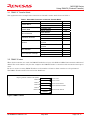
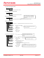
This application note example offers functions of chained transfer mode shown in Table 1.
Table 1. Selectable Functions in Chained Transfer Mode
Item
Definition
8 bits
Transfer Block
16 bits
Selection
Yes
Immediate data
Data in memory
Fixed address
Source Direction
Forward address
Fixed address
Destination Direction
Forward address
Calculation
Transfer Without Calculation Transfer
Function
Function
With
Calculation
Transfer
Function
Single transfer
Burst Transfer
Burst transfer
Interrupts not used
End-of-Transfer Interrupt
Interrupts used
Transfer Data
Yes
Yes
Yes
Yes
Yes
Yes
3.2 DMAC II Index
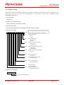
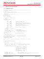
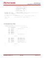
When chain transfers are used, the DMACII index has 4 bytes of CADR1–CADR0 (chain transfer addresses)
added. The total number of bytes that comprise the DMACII index is 12 unless end-of-transfer interrupt is
used.
Be sure to create as many DMACII indices as the number of times a chain transfer is to be performed.
The DMAC II index must be located on the RAM area.
Beginning address of DMACII index (BASE)
MOD
Transfer mode
BASE+2
COUNT
Transfer counter
BASE+4
SADR
Transfer source address
DADR
Transfer destination address
BASE+6
BASE+8
CADR0
BASE+10
Chained transfer address
CADR1
Figure 2.DMAC II Index
REJ05B0640-0100/Rev.1.00
May 2005
Page 3 of 11