1
M32C/80 Series
Using DMACII (Chained Transfer)
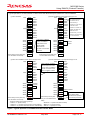
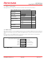
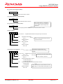
(6) Transfer source address (SADR)
b15
b0
16 bits
Set the source address of transfer.
(7) Transfer destination address (DADR)
b15
b0
16 bits
Set the destination address of transfer.
When COUNT reaches “0”, the peripheral
function interrupt vector that constitutes the
(8) Chained transfer address (CADR)
b31
b0
cause of a DMACII request changes to the
CADR value.
32 bits
Set the beginning address of the DMACII index to which the transfer is chained.
(9) RLVL register
b7
b0
0 0 1 0 0 *
*
*
RLVL2 to RLVL0
FSIT
Stop/Wait Mode Exit Minimum Interrupt Priority Level Control Bit
High-Speed Interrupt Set Bit
Set to “0”
-
DMAC II and high-speed interrupts cannot be
Nothing is assigned.
used at the same time.
Set to “0”
DMAII
DMAC II Select Bit
Set to “1”
-
Nothing is assigned.
Set to “00b”
(10) Interrupt Control Register
b7
0 0 *
Set all interrupt request registers for the
interrupts to be used as the cause of DMAC II
requests.
b0
* 0 1 1 1
ILVL2 to ILVL0
Interrupt Priority Level Select Bit
Set to “111b”
IR
Set the priority level of the interrupt used as
Interrupt Request Bit
the cause of DMAC II request to 7.
Set to “0”
POL
Polarity Switch Bit (INT0IC to INT5IC)
0: Selects falling edge or “L”
1: Selects rising edge or “H”
LVS
Level Sensitive/Edge Sensitive Switch Bit (INT0IC to INT5IC)
0: Edge sensitive
1: Level sensitive
-
Nothing is assigned.
Set to “00b”
REJ05B0640-0100/Rev.1.00
The POL and LVS bits are accommodated in the INT0ICINT5IC registers. In other interrupt request registers, set it
to “0”.
May 2005
Page 6 of 11