1
UM1692
User manual
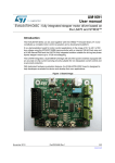
EVAL6472H-DISC: fully integrated stepper motor driver based on
the L6472 and STM32™
Introduction
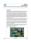
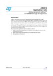
The EVAL6472H-DISC can be used together with the STM32™ firmware library V1.0 and
constitutes a complete motor control evaluation and a development platform.
It is a demonstration board for motor control applications in the range of 8 V to 45 V of DC
bus voltage using the STM32F105RB microcontroller with an internal 128 kB Flash size and
a 64 kB internal RAM and the L6472 fully integrated solution suitable for driving two-phase
bipolar stepper motors up to 1/16 microstepping.
The L6472 device integrates a dual DMOS full bridge with all of the power switches
equipped with an accurate on-chip current sensing circuitry suitable for non-dissipative
current control and overcurrent protection.
With dedicated hardware evaluation features, the EVAL6472H-DISC board is designed to
help developers evaluate the device and develop their own applications.
Figure 1. Board image
April 2015
DocID025487 Rev 2
1/42
www.st.com
42
Contents
UM1692
Contents
1
Main features . . . . . . . . . . . . . . . . . . . . . . . . . . . . . . . . . . . . . . . . . . . . . . . 4
1.1
Target applications . . . . . . . . . . . . . . . . . . . . . . . . . . . . . . . . . . . . . . . . . . . 4
1.2
Description . . . . . . . . . . . . . . . . . . . . . . . . . . . . . . . . . . . . . . . . . . . . . . . . . 4
2
Electrical characteristics of the board . . . . . . . . . . . . . . . . . . . . . . . . . . 5
3
Schematic, layout and bill of material . . . . . . . . . . . . . . . . . . . . . . . . . . . 6
4
General description . . . . . . . . . . . . . . . . . . . . . . . . . . . . . . . . . . . . . . . . . 12
4.1
Power supply . . . . . . . . . . . . . . . . . . . . . . . . . . . . . . . . . . . . . . . . . . . . . . 12
4.2
L6472 stepper motor driver . . . . . . . . . . . . . . . . . . . . . . . . . . . . . . . . . . . 13
4.2.1
Charge pump . . . . . . . . . . . . . . . . . . . . . . . . . . . . . . . . . . . . . . . . . . . . . 14
4.2.2
Advanced current control . . . . . . . . . . . . . . . . . . . . . . . . . . . . . . . . . . . . 14
4.2.3
Overcurrent detection . . . . . . . . . . . . . . . . . . . . . . . . . . . . . . . . . . . . . . 15
4.2.4
Speed profile . . . . . . . . . . . . . . . . . . . . . . . . . . . . . . . . . . . . . . . . . . . . . 15
4.3
STM32F105RB microcontroller . . . . . . . . . . . . . . . . . . . . . . . . . . . . . . . . 15
4.4
Firmware loading . . . . . . . . . . . . . . . . . . . . . . . . . . . . . . . . . . . . . . . . . . . 18
4.5
4.6
4.4.1
DfuSe installation . . . . . . . . . . . . . . . . . . . . . . . . . . . . . . . . . . . . . . . . . . 18
4.4.2
Generate a DFU file from a HEX file . . . . . . . . . . . . . . . . . . . . . . . . . . . 18
4.4.3
Board settings . . . . . . . . . . . . . . . . . . . . . . . . . . . . . . . . . . . . . . . . . . . . 20
4.4.4
DFU loading . . . . . . . . . . . . . . . . . . . . . . . . . . . . . . . . . . . . . . . . . . . . . . 21
Using the EVAL6472H-DISC with the firmware for the GUI (FWGUI) . . . 25
4.5.1
Sanity check of the board with the firmware for the GUI (FWGUI) . . . . 25
4.5.2
Parameters exportation from the GUI to the FW library . . . . . . . . . . . . . 34
Using the EVAL6472H-DISC with the firmware library . . . . . . . . . . . . . . . 36
4.6.1
FW library package contents . . . . . . . . . . . . . . . . . . . . . . . . . . . . . . . . . 36
4.6.2
FW L6472 library description . . . . . . . . . . . . . . . . . . . . . . . . . . . . . . . . . 36
4.6.3
Demonstration sequence description . . . . . . . . . . . . . . . . . . . . . . . . . . 37
4.6.4
Create a project using the FW library package . . . . . . . . . . . . . . . . . . . 41
5
References . . . . . . . . . . . . . . . . . . . . . . . . . . . . . . . . . . . . . . . . . . . . . . . . 42
6
Revision history . . . . . . . . . . . . . . . . . . . . . . . . . . . . . . . . . . . . . . . . . . . 42
2/42
DocID025487 Rev 2
UM1692
List of figures
List of figures
Figure 1.
Figure 2.
Figure 3.
Figure 4.
Figure 5.
Figure 6.
Figure 7.
Figure 8.
Figure 9.
Figure 10.
Figure 11.
Figure 12.
Figure 13.
Figure 14.
Figure 15.
Figure 16.
Figure 17.
Figure 18.
Figure 19.
Figure 20.
Figure 21.
Figure 22.
Figure 23.
Figure 24.
Figure 25.
Figure 26.
Figure 27.
Figure 28.
Figure 29.
Board image . . . . . . . . . . . . . . . . . . . . . . . . . . . . . . . . . . . . . . . . . . . . . . . . . . . . . . . . . . . . . 1
Schematic (microcontroller supply part) . . . . . . . . . . . . . . . . . . . . . . . . . . . . . . . . . . . . . . . . 6
Schematic (microcontroller part) . . . . . . . . . . . . . . . . . . . . . . . . . . . . . . . . . . . . . . . . . . . . . . 7
Schematic (motor driver part) . . . . . . . . . . . . . . . . . . . . . . . . . . . . . . . . . . . . . . . . . . . . . . . . 8
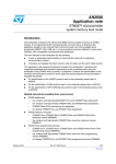
Layout (silk screen). . . . . . . . . . . . . . . . . . . . . . . . . . . . . . . . . . . . . . . . . . . . . . . . . . . . . . . . 9
Layout top and bottom layer . . . . . . . . . . . . . . . . . . . . . . . . . . . . . . . . . . . . . . . . . . . . . . . . . 9
Microcontroller supply section . . . . . . . . . . . . . . . . . . . . . . . . . . . . . . . . . . . . . . . . . . . . . . 12
L6472 block diagram . . . . . . . . . . . . . . . . . . . . . . . . . . . . . . . . . . . . . . . . . . . . . . . . . . . . . 13
Charge pump circuitry. . . . . . . . . . . . . . . . . . . . . . . . . . . . . . . . . . . . . . . . . . . . . . . . . . . . . 14
STM32F105xx and STM32F107xx block diagram . . . . . . . . . . . . . . . . . . . . . . . . . . . . . . . 17
DFU file manager (action). . . . . . . . . . . . . . . . . . . . . . . . . . . . . . . . . . . . . . . . . . . . . . . . . . 18
DFU file manager (generation) . . . . . . . . . . . . . . . . . . . . . . . . . . . . . . . . . . . . . . . . . . . . . . 19
Board settings . . . . . . . . . . . . . . . . . . . . . . . . . . . . . . . . . . . . . . . . . . . . . . . . . . . . . . . . . . . 20
DFU loading . . . . . . . . . . . . . . . . . . . . . . . . . . . . . . . . . . . . . . . . . . . . . . . . . . . . . . . . . . . . 21
DFU file (open) . . . . . . . . . . . . . . . . . . . . . . . . . . . . . . . . . . . . . . . . . . . . . . . . . . . . . . . . . . 22
DFU file (upgrade) . . . . . . . . . . . . . . . . . . . . . . . . . . . . . . . . . . . . . . . . . . . . . . . . . . . . . . . 23
DFU file (confirmation) . . . . . . . . . . . . . . . . . . . . . . . . . . . . . . . . . . . . . . . . . . . . . . . . . . . . 23
DFU file ( download OK) . . . . . . . . . . . . . . . . . . . . . . . . . . . . . . . . . . . . . . . . . . . . . . . . . . . 24
Starting board (BOOT mode) . . . . . . . . . . . . . . . . . . . . . . . . . . . . . . . . . . . . . . . . . . . . . . . 25
Starting board (motor power supply) . . . . . . . . . . . . . . . . . . . . . . . . . . . . . . . . . . . . . . . . . 26
Starting board (USB connection) . . . . . . . . . . . . . . . . . . . . . . . . . . . . . . . . . . . . . . . . . . . . 27
Starting board (error case) . . . . . . . . . . . . . . . . . . . . . . . . . . . . . . . . . . . . . . . . . . . . . . . . . 28
Starting board (board OK) . . . . . . . . . . . . . . . . . . . . . . . . . . . . . . . . . . . . . . . . . . . . . . . . . 29
Starting board (display board ID) . . . . . . . . . . . . . . . . . . . . . . . . . . . . . . . . . . . . . . . . . . . . 30
Starting board (action LEFT key) . . . . . . . . . . . . . . . . . . . . . . . . . . . . . . . . . . . . . . . . . . . . 31
Starting board (action RIGHT key) . . . . . . . . . . . . . . . . . . . . . . . . . . . . . . . . . . . . . . . . . . . 32
Starting board (action RESET key). . . . . . . . . . . . . . . . . . . . . . . . . . . . . . . . . . . . . . . . . . . 33
Parameters exportation . . . . . . . . . . . . . . . . . . . . . . . . . . . . . . . . . . . . . . . . . . . . . . . . . . . 34
Parameters exportation (save file) . . . . . . . . . . . . . . . . . . . . . . . . . . . . . . . . . . . . . . . . . . . 35
DocID025487 Rev 2
3/42
42
Main features
1
UM1692
Main features
The characteristics of the EVAL6472H-DISC board are following:
1.1
DC voltage range from 8 V to 45 V
Maximum load phase current at 3 A r.m.s.
Footprint for external resonator or crystal
Control interface through trimmer - user keys and switch motor input
Control through LED indicators
Interface control by USB and debug outputs
Compatible with SPINFamily evaluation tool
Autonomous board due to embedded firmware
Up to 1/16 microstepping
Optimized layout on 2-layer board - low cost and high thermal performance
Target applications
The demonstration board is designed to fit all typical stepper motor applications - it is an
autonomous board due to embedded firmware.
1.2
Description
The EVAL6472_DISC is downloaded with embedded firmware.
The possibility with this board is double:
To adapt the settings with your specific setup (motor - voltage) by using the dedicated
PC application.
–
4/42
The user is able to save inside the board the specific parameters depending on
a user setup.
Using the board (with user parameters) directly on a site - without a connected PC.
DocID025487 Rev 2
UM1692
2
Electrical characteristics of the board
Electrical characteristics of the board
Table 1. Electrical specifications
Name
Value
Supply voltage (VS)
8 to 45 V
Maximum output current (each phase)
3 A r.m.s
Logic supply voltage (VREG)
3 V (L6472 regulator supply)
Logic interface voltage (VDD)
3.3 V (USB supply)
Low level logic inputs voltage
0V
High level logic input voltage
VDD
Stepping
Up to 1/16 microstepping
Operating temperature
0 to 85 °C
DocID025487 Rev 2
5/42
42
Schematic, layout and bill of material
3
UM1692
Schematic, layout and bill of material
Figure 2. Schematic (microcontroller supply part)
9''
9''
73
8
-
6+(//
6+(//
6+(//
6+(//
86%B9&&
86%'0
86%'3
,'
86%B*1'
9
86%'0
86%'3
&
Q)
.(<6721(
&
)
8
5
1&
9287
9287
1&
/''7 5
&
Q)
*1'
9287
9287
9,1
,2
,2
*1'
9%86
,2
,2
86%'0
9''
86%/&3
86%'3
5
86%B,7
&
Q)
$0
6/42
DocID025487 Rev 2
UM1692
Schematic, layout and bill of material
Figure 3. Schematic (microcontroller part)
9''
9''
9''
5
5
5
5
5
5
5
5
&21)/$7;0
%227
-
&
Q)
-
23(1
9''
Q)
-7$*B7',
-7$*B7&.
&
Q)
)
%227
&
-7$*B17657
-7$*B7'2
5(6(7
&
5
5
5
&
5(6(7
/('B63$5(
/('B(5525
/('B%86<
/('B5($'<
5
5
'
'
5('
6:B02725
%87721B$
%87721B%
'
25$1*(
*5((1
3$
966B
9''
3$
3$
3$
3$
3&
3&
3%
3%
3%
3%
3%
966B
9''B
'
<(//2:
9''
&
&
)
)
9''
*1'
9''
9''
9''
5
9''
5
73
3$B706
86%'3
86%'0
3$B8$57B5;
3$B8$57B7;
3$B8$57B&.
73
73
86%B,7
%2$5'B,'B
%2$5'B,'B
%2$5'B,'B
%2$5'B,'B
5
%86< 5($'<
67&.
63$5( (5525
9''B
966B
3$
3$
3$
3$
3$
3$
3&
3&
3&
3&
3%
3%
3%
3%
&
13
5
5
5
13
13
%227
)/$*
%86<
5
9%$7
3&7$03(557&
3&26&B,1
3&26&B287
3'26&B,1
3'26&B287
8
1567
3&
670)5%7
3&
3&
3&
966$
9''$
3$:.83
3$
3$
9''
*1'
S)
5
9''
5
9''B
966B
3%
3%
%227
3%
3%
3%
3%
3%
3'
3&
3&
3&
3$
3$
<
0+]
63,B166
63,B1&.
63,B0,62
63,B026,
6:
67%<B5(6(7
S)
&
9''
&
5
&
Q)
5
5
Q)
5
&
6
Q)
6:02725
6
Q)
5(6(7
&
&
Q)
-
23(1
/()7
67$576723
6
Q)
&
5
5,*+7
$0
DocID025487 Rev 2
7/42
42
Schematic, layout and bill of material
UM1692
Figure 4. Schematic (motor driver part)
5
96
96
5
&
1)
%$9
5
&
96
Q)
26&287 $'&,1
6:
67&.
67%<B5(6(7
)/$*
%86<
&3
9%227
287$
26&287
8
/+
-
287$
&
&
Q)
Q)
&
)
9
-
$
$
$'&,1
6:
67&.
67%<B5(6
)/$*
%86<B6<1&
&6
&.
6',
6'2
287%
287%
63,B166
63,B1&.
63,B026,
63,B0,62
26&,1
(3$'
26&,1
9''
95(*
Q)
'*1'
5
13
&
73
&
Q)
9''
Q)
;7$/
*1'
73
&
5
13
96$
96$
96%
96%
9
&
96
-
%
%
$*1'
3*1'
3*1'
'
'
73
.(<6721(
$'&,1
$0
Figure 5. Layout top and bottom layer
8/42
DocID025487 Rev 2
UM1692
Schematic, layout and bill of material
Table 2. Bill of material
Item
Qty.
Reference
Value
Package
C1, C16
2
Cap. cer. 10 µF 10 V X7R 0805
10 µF
0805
C2
1
Cap. cer. 1 µF 10 V X7R 0805
1 µF
0805
C3, C4, C10 C13, C17 C19, C21,
C22, C25-C27
14
Cap. cer. 100 nF 50 V X7R 0603
100 nF
0603
C5
1
Cap. cer. 3.3 nF 50 V X7R 0603
3.3 nF
0603
C6
1
Cap. cer. 220 nF 35 V X7R 0603
220 nF
0603
C7
1
Cap. cer. 4.7 nF 50 V X7R 0603
4.7 nF
0603
C8, C15, C20,
C28
4
Cap. cer. 10 nF 50 V X7R 0603
10 nF
0603
C9
1
Cap. tant. 47 µF 6.3 V10% PACK-A
47 µF
3216
C14
1
Cap. elec. 100 µF 63 V
100 µF
CAPES-R10HXX
C23, C24
2
Cap. cer. 20 pF 50 V COG 0603
20 pF
0603
D1
1
Zener regulator
3.6 V
SOD 523
D2
1
Double diode high speed switching
diode
BAV99
SOT23
D3
1
LED red - 0805 -2 mcd - 621 nm
Red
0805
D4
1
LED green - 0805 -6 mcd - 569 nm
Green
0805
D5
1
LED yellow - 0805 -6 mcd - 588 nm
Yellow
0805
D6
1
LED orange - 0805 -2 mcd - 602 nm
Orange
0805
FIX1 - FIX4
4
Hole
3 mn
-
J1-J3
3
Screw connector 2 poles MKDSN
1.5 / 2 - 5.08
MKDSN 1.5 / 2 - 5.08
MKDSN 1.5 / 2 - 5.08
J4
1
JTAG CON-FLAT- 10 x 2 - 180 M
J5
1
USB_B_MINI_AMP_1734035-1
CN-USB
CMS mini USB
J6, J7
2
JUMP254P-M-2
OPEN
STRIP 2x2,54
MIRE1 MIRE3
3
OPTICAL_TARGET
OPTICAL_TARGET
Diam 1mn
R1
1
Trimmer 200 K
200 K
Trimm. 100 x 50 x 110
R2
1
27 K 5% 1/10 W
27 K
0603
R3
1
Res. 7.5 K 5% 1/10 W 0603 SMD
7.5 K
0603
R4, R13
2
Res. 1 M 1/10 W 5% 0603 SMD
1 M
0603
R5
1
Res. 1.5 K 1/10 W 5% 0603 SMD
1.5 K
0603
R6, R8 - R11,
R14, R19, R30
- R32
10
Res. 10 K 5% 1/10 W 0603 SMD
10 K
0603
R7, R12
2
Res. 100 5% 1/10 W
100
0603
CON-FLAT- 10 x 2 - 180 M CON-FLAT- 10 x 2 - 180 M
DocID025487 Rev 2
9/42
42
Schematic, layout and bill of material
UM1692
Table 2. Bill of material (continued)
Item
Qty.
Reference
Value
Package
R15 - R18
4
Res. 470 5% 1/10 W 0603
470
0603
R21, R33
2
Res. 1 K 5% 1/10 W 0603 SMD
1 K
0603
R20, R22,
R23, R34
4
Res. NP 0603
NP
0603
R24 - R27
4
Res. 4.7 K 5% 1/10 W 0603 SMD
4.7 K
0603
R28
1
Res. 100 K 5% 1/10 W 0603 SMD
100 K
0603
R29
1
Res. NP 0805
NP
0805
S1-S3
3
Switch button SMD
EVQQ2D03W
CMS 6.5 x 6 x 3.1
TP1, TP2, TP4
- TP7
6
Test point red
KEYSTONE-5000
TH
TP3
1
Test point black
KEYSTONE-5001
TH
U1
1
IC REG 1300MA LN 3.3 V
LD1117D33TR
SO8
U2
1
USBLC6-2P6
USBLC6-2P6
SOT 666
U3
1
L6472 microstepping motor driven
L6472
HTSSOP28
U4
1
IC, MCU, RISC, 72 MHz, 3.6 V,
32-bit, 64-pin, LQFP
STM32F105RBT6
LQFP64 10 x 10
Y1
1
XTAL 8 MHz-30PPM-20 pF
8 MHz
HC49/US-SM
10/42
DocID025487 Rev 2
UM1692
General description
4
General description
4.1
Power supply
The EVAL6472H-DISC board is designed to be powered via:
Connector J1: power of the motor and also motor control driver.
USB connector J5: power of the microcontroller and logic control.
The USB cable supplies the digital part through a dedicated LDO (U1) providing 3.3 V.
The motor power must be set according to the voltage required by the user motor.
Note:
Both the supply sources (USB connector and J1 connector) must be present to make
the board operative.
Figure 6. Microcontroller supply section
9''
9''
73
8
-
6+(//
6+(//
6+(//
6+(//
86%B9&&
86%'0
86%'3
,'
86%B*1'
9
86%'0
86%'3
&
Q)
.(<6721(
&
)
8
5
1&
9287
9287
1&
/''7 5
&
Q)
*1'
9287
9287
9,1
,2
,2
*1'
9%86
,2
,2
86%'0
9''
86%/&3
86%'3
5
86%B,7
&
Q)
$0
DocID025487 Rev 2
11/42
42
General description
4.2
UM1692
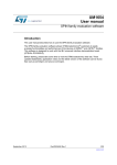
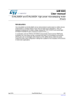
L6472 stepper motor driver
The L6472 is an advanced fully integrated solution suitable for driving two-phase bipolar
stepper motors with microstepping. It integrates a dual low RDS(on) DMOS full bridge.
Features
Operating voltage: 8 - 45 V
7.0 A out peak current (3.0 A r.m.s.)
Low RDS(on) power MOSFETs
Programmable speed profile
Programmable power MOS slew rate
Predictive current control with adaptive decay
Non-dissipative current sensing
Up to 1/16 microstepping
Sensorless stall detection
SPI interface
Low quiescent and standby currents
Programmable non-dissipative overcurrent
Two levels of overtemperature protection
Figure 7. L6472 block diagram
9''
26&,1
0+]
2VFLOODWRU
26&287 $'&,1
95(*
9%227
&KDUJH
SXPS
([W2VFGULYHU
&ORFNJHQ
$'&
67%<567
&3
96$
9
9ROWDJH5HJ
)/$*
9 ERRW
9 ERRW
+6 $
96$
+6 $
5HJLVWHUV
287$
9 ''
+6 $
287$
/6 $
+6 $
/6 $
/6 $
/6 $
&RQWURO
/RJLF
3*1'
96%
+6 %
/6 %
&6
9 ERRW
9 ERRW
96%
+6 %
/6 %
63,
&.
6'2
+6 %
+6 %
287%
6',
287%
%86<6<1&
67&.
7HPSHUDWXUH
VHQVLQJ
&XUUHQW'$&V
&RPSDUDWRUV
/6 %
/6 %
3*1'
9 ''
&XUUHQW
VHQVLQJ
6:
'*1'
$*1'
$0Y
12/42
DocID025487 Rev 2
UM1692
General description
Table 3. L6472 Recommended operating conditions
Symbol
Parameter
Value
Unit
VDD
Logic Interface supply voltage
3.3
V
VS
Motor supply voltage
VSA = VSB = VS
8 ÷ 45
V
VOUT_diff
Differential between voltage VSA, OUTI1A, OUT2A, PGND
and VSB, OUT1B, OUT2B, PGND pins
VSA = VSB = VS
Up to 45
V
VREG in
Logic supply voltage
VREG internal
3
V
VADC
Integrated ADC input voltage range (ADCIN pin)
0 ÷ VREG
V
4.2.1
Test condition
Charge pump
The L6472 device uses an internal charge pump for driving correctly the integrated
MOSFETs, a voltage higher than the motor power supply. The charge pump is obtained
through an oscillator and few external components.
Figure 8. Charge pump circuitry
96
&
Q)
'
%$9 &
Q )
9%227
&3
8
96$ 96$ 96% 96%
/+
$09
4.2.2
Advanced current control
The following configuration gives good results with most of motors:
Minimum ON time = 4 µs.
Minimum OFF time = 21 µs.
Max. fast decay = 10 µs.
Max. fast decay at step change = 16 µs.
Target switching time = 48 µs.
Predictive current control enabled.
The impact of the timing parameters are explained in the application note AN4158: “Peak
current control with automatic decay adjustment and predictive current control: basics and
setup”.
DocID025487 Rev 2
13/42
42
General description
UM1692
The target phase current is set through the TVAL registers. The TVAL determinates the
current corresponding to the peak of the sine wave (microstepping operation).
4.2.3
Overcurrent detection
The overcurrent protection detection is implemented by measuring the current flowing into
each integrated MOSFET.
The overcurrent protection threshold should be set just above the current rating of the
motor:
IOCDth > Imax,r.m.s. × √2
For example: if the maximum phase current of the motor is 2 Ar.m.s., the overcurrent
protection should be set to about 3 A.
Warning:
4.2.4
Important - it is strongly discouraged to disable the
overcurrent shutdown. It may result in critical failures.
Speed profile
The max. speed parameter is the maximum speed the motor will run. By default, it is about
1000 step/s. That means, if you send a command to run at 2000 step/s, the motor speed is
limited at 1000 step/s.
This is an important safety feature in the final application, but not necessarily useful to
evaluate the device performances. Setting the parameter to high values (e.g. 6000 step/s)
allows evaluating the maximum speed which can be achieved by the application under test
through the speed tracking command (Run), but it probably limits the possibility to use
positioning commands (“Move”, “GoTo”, etc.).
The “Full step” speed parameter indicates the speed at which the system switches from
microstepping to full step operation.
4.3
STM32F105RB microcontroller
The STM32F105xx incorporates the high-performance ARM®Cortex™-M3 32-bit RISC core
operating at a 72 MHz frequency, high-speed embedded memories (Flash memory up to
256 Kbytes and SRAM 64 Kbytes), and an extensive range of enhanced I/O and peripherals
connected to two APB buses. All devices offer two 12-bit ADCs, four general-purpose 16-bit
timers plus a PWM timer, as well as standard and advanced communication interfaces: up
to two I2Cs, three SPIs, two I2Ss, five USARTs, a USB OTG FS and two CANs.
The STM32F105xx operates in the -40 to +105 °C temperature range, from a 2.0 to 3.6 V
power supply. A comprehensive set of power-saving mode allows the design of low-power
applications.
The STM32F105xx offers devices in three different package types: from 64 pins to 100 pins.
Depending on the device chosen, different sets of peripherals are included.
These features make the STM32F105xx and STM32F107xx connectivity line
microcontroller family suitable for a wide range of applications such as motor drives and
application control, medical and handheld equipment, industrial applications, PLCs,
14/42
DocID025487 Rev 2
UM1692
General description
inverters, printers and scanners, alarm systems, a video intercom, HVAC and home audio
equipment.
Please refer to the STM32F105xx datasheet for an overview of the complete range of
peripherals proposed in this family.
Please refer to the STM32F105xx reference manual (RM0008) to get more information on
the microcontroller operation.
The STM32F105RBT6 has a 64-pin LQFP package with 128 KBytes Flash memory and
operates in the -40 to +85 °C temperature range.
DocID025487 Rev 2
15/42
42
General description
UM1692
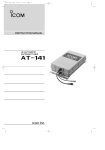
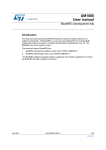
Figure 9 shows the general block diagram of the STM32F105xx and STM32F107xx family.
Figure 9. STM32F105xx and STM32F107xx block diagram
(70
7UDFH7ULJ
,EXV
&RUWH[0&38
6\VWHP
19,&
*3'0$
#9''
;7$/RVF
0+]
1567
9''$
966$
26&B,1
26&B287
&B2
,:'* 3&/.
3&/.
+&/.
)&/.
3//
6WDQGE\
LQWHUIDFH
9%$7 9WR9
#9%$7
;7$/N+]
%DF NXS
UHJLVWHU
57&
$:8
'35$0.% '35$0.%
26&B,1
26&B287
7$03(557&
$/$506(&21'287
%DFNXSLQWHUIDFH
86%27*)6
$+%WR
$3%
$+%WR
$3%
(;7,7
:.83
*3,2SRUW&
3'>@
*3,2SRUW'
3(>@
*3,2SRUW(
$3%) PD[ 0+]
3&>@
7,0
&KDQQHOV (75
DV$)
7,0
&KDQQHOV (75
DV$)
7,0
&KDQQHOV (75
DV$)
7,0
&KDQQHO V(75
DV$ )
5;7;&76576
&.DV$)
86$57
5;7;&76576
&.DV$)
86$57
5;7;DV$)
8$57
5;7;DV$)
8$57
63,,6
[[E
LW
7,0
63,,6
[[E
LW
63,
::'*
86$57
026,6'0,620&.
6&.&.166:6DV$)
026,6'0,620&.
6&.&.166:6DV$)
,&
6&/6'$ 60%$
DV$)
,&
6&/6'$60%$
DV$)
E[ &$1
&$1B7;DV$)
&$1B5;DV$)
65$0%
7HP SVHQVRU
95()
95()
3253'5
#9''$
'0$(WKHUQHW
*3,2SRUW%
3
$'&B,1V
FRPPRQWR
$'&$'&
6XSSO\
VXSHUYLVLRQ
,QW
3//
5HVHW
FORFN
FRQWURO
966
39'
3//
(WKHUQHW 0$&
3%> @
5;7;&76576
&.DV$)
325
5HVHW
5&/6
*3'0$
*3,2SRUW$
3
026,0,62
6&.166DV$)
5&+6
3//
3$> @
&KDQQHOV
FRPSO &KDQQHOV
%.,1(75LQSXWDV$)
#9''$
FKDQQHOV
65$0.%
$)
ELW
65$0
.%
FKDQQHOV
9'' WR9
#9''
$3%)PD[ 0+]
62)
9%86
,'
'0
'3
)ODVK.%
$+%
0,,B7;'>@50,,B7;'>@
0,,B7;B&/.50,,B7;B&/.
0,,B7;B(150,,B7;B(1
0,,B5;'>@50,,B5;'>@
0,,B5;B(550,,B5;B(5
0,,B5;B&/.50,,B5()B&/.
0,,B5;B'950,,B&56B'9
0,,B&56
0,,B&2/50,,B&2/
0'&
0',2
336B287
9ROWDJHUHJ
9WR9
'EXV
)PD[ 0+]
3RZHU
9''
,QWHUIDFH
73,8
6:-7$*
)ODVKO REO
DV$)
1-7567
-7',
-7&.6:&/.
-7066:',2
-7'2
DV$ )
%XV 0DWUL [
75$&(&/.
75$&('>@
E[ &$1
EL W$'& ,)
ELW$'&
,)
&$1B7;D
V $)
&$1B5;DV$)
7,0
,) ELW '$&
,)
'$&B287DV$)
7,0
ELW'$& '$&B287DV$)
#9''$
#9''$
DL
16/42
DocID025487 Rev 2
UM1692
4.4
General description
Firmware loading
This section describes how to load firmware to the board by using the DfuSe demonstration
software.
4.4.1
DfuSe installation
You need first to download the DfuSe demonstration software from: www.st.com.
The DfuSe tool is referenced under the development suite STSW-STM32080
Once downloaded, run the setup.exe file.
More details on DfuSe are given in the UM0412 user manual.
4.4.2
Generate a DFU file from a HEX file
If the file you want to download to the discovery board is not a DFU file but a HEX file, you
will need first to convert it.
In this purpose,
Start the DFU file manager (V3.0.3 or greater) which has been installed with the DfuSe.
Choose “I want to GENERATE a DFU file from S19, HEX or BIN files”.
Figure 10. DFU file manager (action)
DocID025487 Rev 2
17/42
42
General description
UM1692
Click on the “S19 or Hex”… button.
Select in the open dialog box the File of type “hex Files”, select the HEX file and click
“OK”.
Click on the “Generate…” button.
Give a name to the *.dfu file and click on the “Save” button.
Figure 11. DFU file manager (generation)
18/42
DocID025487 Rev 2
UM1692
4.4.3
General description
Board settings
To be able to download firmware, the discovery board should be started in the “DFU” mode.
In this purpose:
1.
Remove the jumper from the BOOT pins.
2.
Plug a USB cable between the discovery board and the PC.
It does not matter if the VS connector is plugged or not to a supply voltage.
Figure 12. Board settings
DocID025487 Rev 2
19/42
42
General description
4.4.4
UM1692
DFU loading
At this step, you are now ready to perform the firmware upgrade.
1.
Start the “DfuSeDemo.exe”.
2.
You must have an “STM Device in DFU Mode” in the list of the “Available DFU
Devices”. Else, it means that your board is not correctly configured or not connected to
the PC.
Figure 13. DFU loading
3.
20/42
In the “Upgrade or Verify Action” group, click on the “Choose…” button.
DocID025487 Rev 2
UM1692
General description
4.
Select the *.dfu file of your choice in the open dialog box and click on the “Open”
button.
Figure 14. DFU file (open)
DocID025487 Rev 2
21/42
42
General description
5.
UM1692
Click on the “Upgrade” button.
Figure 15. DFU file (upgrade)
6.
If this dialog box appears, click “Yes”.
Figure 16. DFU file (confirmation)
22/42
DocID025487 Rev 2
UM1692
General description
7.
Once the download is performed, you should have:
Figure 17. DFU file ( download OK)
8.
Do no forget to put the jumper back on the BOOT pins in order to restart the discovery
board to the normal mode!
DocID025487 Rev 2
23/42
42
General description
4.5
UM1692
Using the EVAL6472H-DISC with the firmware for the GUI
(FWGUI)
By default the discovery board is loaded with the FWGUI. This firmware offers the capability
to connect the board with a GUI: the SPINFamily evaluation tool. This GUI provides direct
access to all L6472 registers and allows sending application commands.
Both the FWGUI and the GUI can be downloaded from the “Design Resources” page of the
L6472:
The FWGUI can be downloaded to the discovery board as detailed in Section 4.4.
The behavior of the GUI is detailed in the Help.chm file which is provided with the setup file
of the GUI.
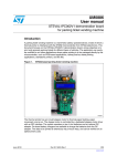
4.5.1
Sanity check of the board with the firmware for the GUI (FWGUI)
At the startup of the FWGUI, a sanity check is performed to confirm the discovery board is
working correctly. The status is returned via the board LEDs.
To have a correct execution of the sanity check, please follow the steps below:
1.
Place a jumper on the BOOT pins (bottom left corner of the board):
Figure 18. Starting board (BOOT mode)
24/42
DocID025487 Rev 2
UM1692
General description
2.
Connect the board to a 5 V - 45 V DC power supply:
Figure 19. Starting board (motor power supply)
DocID025487 Rev 2
25/42
42
General description
3.
UM1692
Plug a USB cable (which must at least provide a power supply).
Figure 20. Starting board (USB connection)
4.
26/42
The board should switch on automatically.
DocID025487 Rev 2
UM1692
General description
5.
At this step:
a)
If a problem is detected, the “ready” LED (green) and the “error” LED (red) will
switch on without blinking. This means that:
–
either the board ID is not recognized by the FW (bad FW versions used)
–
or there is a problem with the SPI (no connection between the MCU and the L6472
via the SPI)
–
or there is no 5 V - 45 V DC power supply.
Figure 21. Starting board (error case)
DocID025487 Rev 2
27/42
42
General description
UM1692
b)
If no problem is detected, the LEDs will start an infinite two-step loop:
–
In the first step, the four LEDs will switch on one after the other by starting by the
green one and ending by the yellow one.
Figure 22. Starting board (board OK)
28/42
DocID025487 Rev 2
UM1692
General description
–
In the second step, only the LEDs which correspond to the board ID are switched
on all at the same time.
For the L6472 device, there are the green, red, yellow LEDs.
Figure 23. Starting board (display board ID)
DocID025487 Rev 2
29/42
42
General description
6.
UM1692
Press the LEFT button and check the two-step loop stops after a few seconds. Only the
green LED remains switched on.
Figure 24. Starting board (action LEFT key)
30/42
DocID025487 Rev 2
UM1692
General description
7.
Press the “RIGHT” button and check the two-step loops restarts.
Figure 25. Starting board (action RIGHT key)
DocID025487 Rev 2
31/42
42
General description
8.
UM1692
Press the RESET button and check that the LEDs restart there two-step loop after the
board reset.
Figure 26. Starting board (action RESET key)
Note:
32/42
Please note that once you have connected the discovery board to the GUI, the LEDs
meaning is different. You then need to restart the board to perform a new auto-check and to
have a valid status of the LEDs.
DocID025487 Rev 2
UM1692
4.5.2
General description
Parameters exportation from the GUI to the FW library
Once you have customized the L6472 parameters with the GUI, you can export them to a
header file in order to use it with the FW library.
In this purpose:
1.
Press the “header file” button on the main window of the GUI.
Figure 27. Parameters exportation
2.
Replace the existing “dspin_config.h” of your current FW library by the new one.
DocID025487 Rev 2
33/42
42
General description
UM1692
Figure 28. Parameters exportation (save file)
3.
34/42
Then you only need to recompile your project as usual to use the exported parameters.
DocID025487 Rev 2
UM1692
4.6
General description
Using the EVAL6472H-DISC with the firmware library
The L6472 firmware library is supplied as an IAR workspace with a source, include project
files. If you are using an IAR design environment, you just need to load the “dspin.eww” file
and use the “fwlibrairies_dspin_discoverykit” project which is already active.
If you are using a different design environment, you will find instructions in this user manual
to build a new project on your preferred IDE.
The L6472 firmware library is also supplied as an executable in a HEX and in a DFU format.
It can be loaded into the EVAL6472H-DISC board as explained in Section 4.4 on page 17.
4.6.1
FW library package contents
FW L6472 library
–
–
/stm32f10x/CMSIS
Library used by the L6472 FW library
STM32F10x Standard Peripherals Library Drivers
–
Described in Section 4.6.2.
CMSIS library
/stm32f10x/STM32F10x_StdPeriph_Driver Library used by the L6472 FW library
IAR workspace files
–
/user_motion/project/ewarm6/fwlibraries/dspin/dspin.eww
- a workspace file
–
/user_motion/project/ewarm6/fwlibraries/dspin/settings/dspin.wsdt
- a workspace settings file
–
/user_motion/project/ewarm6/fwlibraries/dspin/discoverykit
- a directory containing L6472 discovery board project files and subdirectories
–
/user_motion/project/ewarm6/fwlibraries/dspin/discoverykit/Debug/Exe/
- a directory containing the *.hex and *.dfu executable files
–
/user_motion/project/ewarm6/fwlibraries/dspin/pcc009v2
- a directory containing PCC009V2 board project files and subdirectories.
4.6.2
FW L6472 library description
The FW L6472 library has the following features
Register read, write and check
Register values conversion
Device configuration
Motion commands
FLAG and BUSY interrupts management
Button interrupts management
Step “Clock mode” management
Initialization routine using “GoUntil” and “ReleaseSW” commands
“Daisy Chain” mode.
The FW L6472 library has been tested on the L6472H DISCOVERY board R1. The main
program contains a commented demonstration sequence which uses all the FW L6472
DocID025487 Rev 2
35/42
42
General description
UM1692
library supported features. This sequence is interactive and to proceed to the end some
user action is necessary.
For the “GoUntil” feature demonstration, when the LED SPARE is blinking for the first time,
the user shall close the SW MOTOR jumper J8. This triggers a switch turn on event at the
L6472 SW pin.
For the “ReleaseSW” feature demonstration, when the LED SPARE is blinking again, the
user shall open the SW MOTOR jumper J8. This triggers a L6472 SW pin release.
At the end of the demonstration sequence, the GPIO connected to the LEFT and RIGHT
buttons are configured to trigger interrupts on the microcontroller:
On a LEFT button press, the microcontroller starts the motor at quarter of max. speed if it is
stopped or doubles the motor speed if it is already running.
On a LEFT button press, the microcontroller disables the power bridges after a smooth stop
if the motor is running at minimum speed or halves the motor speed if the motor is running
above minimum speed.
Even if the “Daisy Chain” mode is supported in the L6472 FW library, the L6472 Discovery
board HW does not allow it. Please contact ST support if you want more information on the
“Daisy Chain” mode testing or implementation.
The FW L6472 library consists of the following files
4.6.3
user_motion/dspin/inc/stm32f10x_conf.h Library configuration file
user_motion/dspin/src/stm32f10x_it.c
Interrupt handlers
user_motion/dspin/inc/stm32f10x_it.h
Header for stm32f10x_it.c
user_motion/dspin/inc/clock.h
System clock setup related header
user_motion/dspin/src/clock.c
System clock source file
user_motion/dspin/inc/dspin.h
L6472 definitions header
user_motion/dspin/src/dspin.c
L6472 routines source file
user_motion/dspin/inc/dspin_config.h
L6472 configuration parameters (this file
can be generated by the GUI)
user_motion/dspin/inc/main.h
Main header file
user_motion/dspin/src/main.c
Main program
user_motion/dspin/inc/pre_include.h
First header file included by the
preprocessor
user_motion/dspin/readme.txt
Information on the files
Demonstration sequence description
The demonstration sequence description is for one L6472 device without daisy chaining.
The application commands used are noted after the pipe character. The application
commands traffic can be seen on the SPI interface, pins 18, 19, 20 and 23 which are
respectively SDO, CK, SDI and CS.
36/42
DocID025487 Rev 2
UM1692
General description
Initialization and configuration
1.
Initialize peripherals used by L6472.
2.
LED_READY (GREEN) is lighted up, other LEDs are switched off.
3.
LED check sequence:
a)
LED_ERROR (RED) is switched ON
b)
LED_BUSY (ORANGE) is switched ON
c)
LED_SPARE (YELLOW) is switched ON
d)
LED_ERROR (RED), LED_BUSY (ORANGE) and LED_SPARE (YELLOW) are
switched OFF.
4.
Resets and puts L6472 into the standby mode. The L6472 STBY_RESET pin goes low
for a few hundreds of µs and then goes high.
5.
Program all L6472 registers | SetParam (PARAM, VALUE).
Flag signal management
6.
Read status register content | GetStatus
7.
Interrupt configuration for FLAG signal
8.
Motor runs at constant speed of a 400 steps/s forward direction | Run (DIR, SPD)
9.
Tentative to write to the current motor absolute position register while the motor is
running, as a consequence the LED_ERROR (RED) is lighted up | SetParam
(PARAM, VALUE)
10. “Get Status” to clear FLAG due to non performable command, as a consequence the
LED_ERROR (RED) is switched off | GetStatus
11. Motor stops smoothly | SoftStop
12. Wait until not busy - busy pin test (L6472 pin 22).
Busy signal management
13. Interrupt configuration for BUSY signal
14. Motor moves by 100,000 steps in a reverse direction | Move (DIR, N_STEP)
15. During busy time the LED_BUSY (ORANGE) is switched ON
16. L6472 disables the power bridges after a deceleration to zero phase | SoftHiZ
17. LED_BUSY (ORANGE) is switched OFF.
The LED_BUSY after the point 7 and the LED_ERROR after the point 13 are tied
respectively to the BUSY/SYNC pin and the FLAG pin. So for example they are lighted up
when the motor accelerates or decelerates. This is happening in the remaining part of the
demonstration although not mentioned.
DocID025487 Rev 2
37/42
42
General description
UM1692
Various application commands examples
18. Motor moves by 60,000 steps forward | Move (DIR, N_STEP)
19. Wait until not busy - busy pin test (L6472 pin 22).
20. Sends L6472 command setting hold duty cycle to 0.5%, sends L6472 command
changing run duty cycle to 5% | SetParam (PARAM, VALUE)
21. Motor runs at constant speed of 50 steps/s in a reverse direction | Run (DIR, SPD)
22. Motor softly stops after a few seconds | SoftStop
23. RESET KVAL_HOLD to initial value, RESET KVAL_RUN to initial value | SetParam
(PARAM, VALUE)
24. Wait until not busy - busy status check in “Status” register | GetStatus
25. Motor moves by 100,000 steps forward | Move (DIR, N_STEP)
26. Wait until not busy - busy status check in “Status” register | GetStatus
27. Test of the Flag pin (L6472 pin 24) by polling, wait in endless cycle if problem is
detected.
28. Motor moves to its home position | GoHome
29. Wait until not busy - busy pin test (L6472 pin 22).
30. Motor goes to absolute position 65535 through the shortest path | GoTo (ABS_POS)
31. Wait until not busy - busy pin test (L6472 pin 22).
32. Motor goes in a forward direction to absolute position 131071 | GoTo_DIR (DIR,
ABS_POS)
33. Wait until not busy - busy pin test (L6472 pin 22).
34. Read run duty cycle (dSPIN_KVAL_RUN) parameter from L6472, read intersect speed
(dSPIN_INT_SPD) parameter from L6472 | GetParam(PARAM)
35. “Read Status” register content | GetStatus
36. Read absolute position (dSPIN_ABS_POS) parameter from L6472 |
GetParam(PARAM)
37. Reset position counter, actually | ResetPos
38. Read absolute position (dSPIN_ABS_POS) parameter from L6472 |
GetParam(PARAM)
39. L6472 disable power stage (high impedance) immediately, as a consequence the
L6472 supply current drops | HardHiZ.
38/42
DocID025487 Rev 2
UM1692
General description
“Go Until” example
40. Interrupt configuration for the SW MOTOR
41. Motor motion in a forward direction at speed 400 steps/s until the user puts a jumper on
J8, the LED_SPARE (YELLOW) toggles until the user puts a jumper on J8 | GoUntil
(ACT, DIR, SPD)
42. Motor stops
43. The LED_SPARE (YELLOW) is switched off.
44. Wait until not busy - busy pin test (L6472 pin 22).
45. Motor moves by 50,000 steps reverse | Move (DIR, N_STEP)
46. Motor moves to the position saved by the GoUntil command into the MARK register, so
50000 steps forward | GoMark
47. Wait until not busy - busy pin test (L6472 pin 22).
48. Nothing happens during a few seconds.
Release SW example
49. Motor motion in a reverse direction at minimum speed until the user removes the
jumper on J8, the LED_SPARE (YELLOW) toggles until the user removes the jumper
on J8 | ReleaseSW (ACT, DIR)
50. The LED_SPARE (YELLOW) is switched off.
51. Motor moves by 100,000 steps forward | Move (DIR, N_STEP)
52. Wait until not busy - busy pin test (L6472 pin 22).
53. Motor goes to home position set by the “ReleaseSW” command | GoHome
54. Wait until not busy - busy pin test (L6472 pin 22).
Step clock mode example
55. “Get Status” to clear FLAG due to switch turn-on event (falling edge on the SW pin) |
GetStatus
56. Motor runs in the step clock mode at 2000 steps/s in a forward direction for a few
seconds while a 2 kHz clock signal from the MCU is applied to the L6472 STCK pin
(25) | StepClock (DIR)
57. The above cited clock is stopped.
Buttons interrupt example
58. Buttons interrupt configuration:
a)
Button_A
- Starts the motor at quarter of max. speed if it is stopped | Run (DIR, SPD)
- Doubles the motor speed if it is already running | Run (DIR, SPD)
b)
Button_B
- Disables the power bridges after a smooth stop if the motor is running at
minimum speed | SoftHiZ
- Halves the motor speed if the motor is running above minimum speed | Run
(DIR, SPD).
DocID025487 Rev 2
39/42
42
General description
4.6.4
UM1692
Create a project using the FW library package
Using your preferred IDE, create a new project.
In project options, properties or settings
Select for the device, the ST STM32F105xB.
Use the CMSIS library.
Edit the preprocessor defined symbols and add:
STM32F10X_CL
USE_STDPERIPH_DRIVER
ST_DSPIN_L6472H_DISCOVERY
Edit the preprocessor including directories and add:
$PROJ_DIR$\…\…\…\…\…\…\stm32f10x\CMSIS\CM3\DeviceSupport\ST\STM32F10x
$PROJ_DIR$\…\…\…\…\…\…\stm32f10x\STM32F10x_StdPeriph_Driver\inc
$PROJ_DIR$\…\…\…\…\…\dspin\inc
Where $PROJ_DIR$ is a variable containing the path to the project directory.
Add the required library source files:
startup_stm32f10x_cl.s
system_stm32f10x.c
misc.c
stm32f10x_exti.c
stm32f10x_flash.c
stm32f10x_gpio.c
stm32f10x_rcc.c
stm32f10x_spi.c
stm32f10x_tim.c
For the debugger, for example, select the ST-LINK and configure it to run to main, to verify
download, to use the Flash loader and to override the default *.board file with the
FlashSTM32F105xB.board.
40/42
DocID025487 Rev 2
UM1692
5
References
References
This user manual provides information on the hardware features and use of the
EVAL6472H-DISC board along with the demonstration firmware and software. For
additional information, refer to the following:
6
1.
STM32F105xx/STM32F107xx datasheet (CD00220364)
2.
STM32F101xx, STM32F102xx, STM32F103xx, STM32F105xx and STM32F107xx
advanced ARM®-based 32-bit MCUs reference manual (RM0008).
Revision history
Table 4. Document revision history
Date
Revision
12-Dec-2013
1
Initial release.
2
Updated Section : Introduction on page 1, Table 2 on
page 9 and Section 4.2.1 on page 13 (replaced
“L6472H” by “L6472”).
Removed Figure 5. Layout (silk screen) from page 9.
Replaced “dSPIN” by “L6472” and/or “motor” in the
whole document.
Updated Table 3 on page 13 (minor modifications).
Updated Section 4.5 on page 24 (replaced “FWPSPIN”
by “FWGUI”, removed “dSPIN” and web link).
Updated text above Figure 23 on page 29 (removed
L6470 device step).
Updated Section 4.5.2 on page 33 and Section 4.6.2 on
page 35 ( (removed L6470 device/board).
Updated Section 4.6.4 on page 40 (replaced “L6470H”
by “6472H”).
Updated 20. in Section : Various application commands
examples on page 38 (minor modifications).
Updated 1. and 2. in Section 5 on page 41.
Minor modifications throughout document.
17-Apr-2015
Changes
DocID025487 Rev 2
41/42
42
UM1692
IMPORTANT NOTICE – PLEASE READ CAREFULLY
STMicroelectronics NV and its subsidiaries (“ST”) reserve the right to make changes, corrections, enhancements, modifications, and
improvements to ST products and/or to this document at any time without notice. Purchasers should obtain the latest relevant information on
ST products before placing orders. ST products are sold pursuant to ST’s terms and conditions of sale in place at the time of order
acknowledgement.
Purchasers are solely responsible for the choice, selection, and use of ST products and ST assumes no liability for application assistance or
the design of Purchasers’ products.
No license, express or implied, to any intellectual property right is granted by ST herein.
Resale of ST products with provisions different from the information set forth herein shall void any warranty granted by ST for such product.
ST and the ST logo are trademarks of ST. All other product or service names are the property of their respective owners.
Information in this document supersedes and replaces information previously supplied in any prior versions of this document.
© 2015 STMicroelectronics – All rights reserved
42/42
DocID025487 Rev 2