1
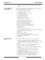
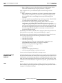
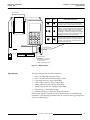
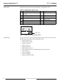
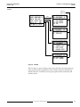
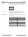
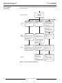
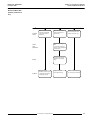
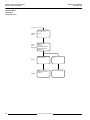
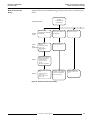
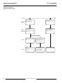
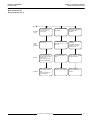
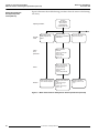
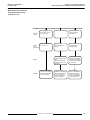
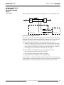
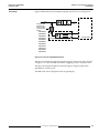
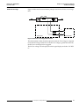
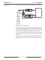
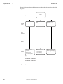
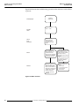
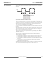
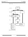
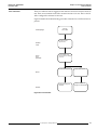
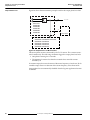
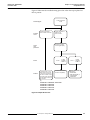
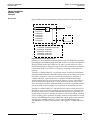
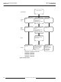
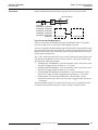
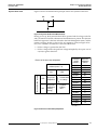
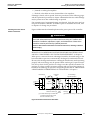
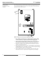
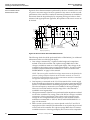
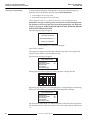
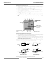
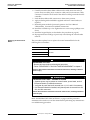
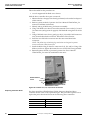
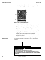
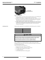
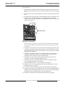
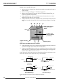
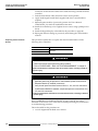
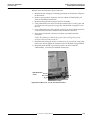
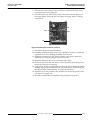
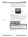
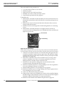
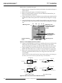
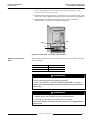
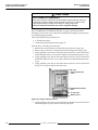
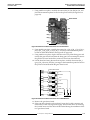
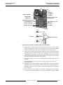
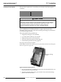
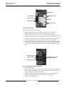
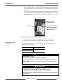
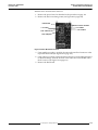
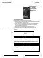
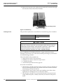
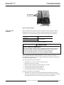
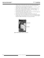
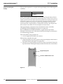
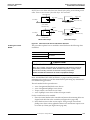
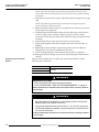
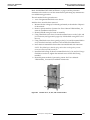
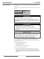
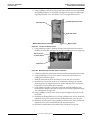
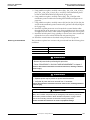
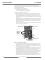
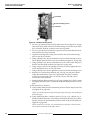
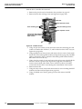
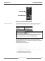
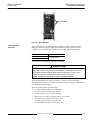
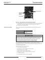
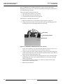
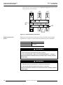
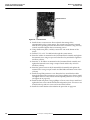
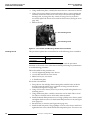
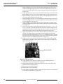
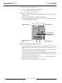
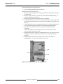
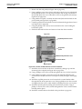
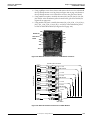
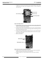
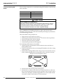
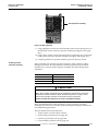
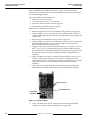
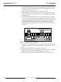
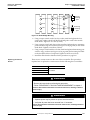
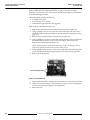
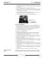
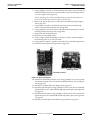
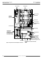
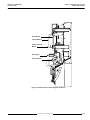
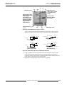
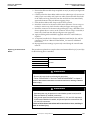
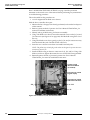
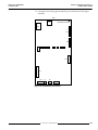
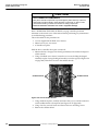
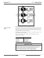
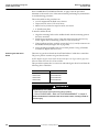
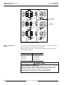
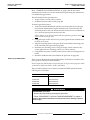
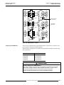
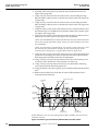
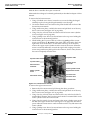
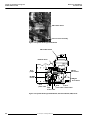
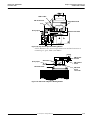
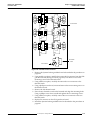
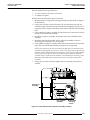
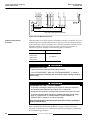
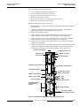
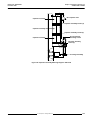
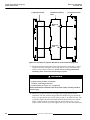
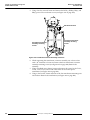
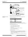
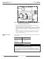
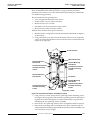
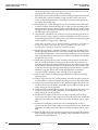
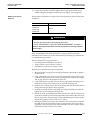
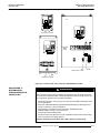
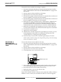
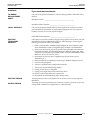
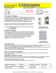
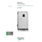
Chapter 4—Equipment Change Out
ATV66U90N4 and ATV66D12N4
Bulletin No. VD0C06S701
December 1996
The tools needed for this procedure are:
•
•
•
•
•
1/4” drive metric socket set, 5.5 to 14 mm
Needle nose pliers
Torque wrench, set to 35.4 lb-in (4 N•m)
Flat blade screw drive sockets for torque wrench
Control basket procedure tool list, page 103.
To install the fan:
1. With the drive controller inverted, thread the J6 connector from the new fan
through the fan lead hole in the back of the drive controller (see Figure 59 on
page 110).
2. Install the new twin fan. Ensure the label side of the side of the twin fan is
facing towards the heat sink.
3. Install the twin fan mounting bracket. Install and tighten the two mounting
screws.
4. With the drive controller returned to its upright position, route the J6
connector and wire lead diagonally over to the right side of the controller (see
Figure 59 on page 110).
J6 connector
Fan lead routing
Figure 59: Fan Lead Routing
NOTE: When routing the wire in the above step, the J6 connector and attached fan leads
are routed between the back of the heat sink and the underside of the printed circuit board.
5. Continue to route the J6 connector and wire leads along the right side of the
controller, around the outside of the top right corner, and under the voltage
regulator heat sink bar. Attach the J6 connector at the top of the power board.
(See Figure 59 on page 110).
6. Fit the drive controller chassis to the controller back cover. Using a drive
socket (or a phillips screw driver, as necessary), tighten the four screws
holding the drive controller chassis to the back cover.
7. Install the two side panels by sliding them towards the bottom of the
controller until the mounting tabs lock into place.
8. Install the controller bottom cover. Using a phillips screw driver, tighten the
four screws holding the bottom cover in place.
9. Install the IP20 protection cover (see Figure 56 on page 105).
10. Install the controller top cover. Using a phillips screw driver, tighten the two
screws holding the top cover in place.
11. Connect J1 at the bottom of the power board.
12. Using a torque wrench and a flat blade screw driver socket, install and tighten
the field wiring on the termination points on connector J2. See Receiving and
Installation Manual VDOC06S304_ for torque specifications.
13. Install the control basket as described in the procedure on page 103.
110
© 1996 Square D All Rights Reserved