1
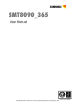
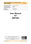
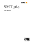
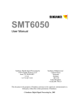
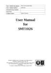
SMT8081
User Manual
Version 1.0
Page 2 of 13
SMT8081 User Manual
Revision History
Date
Comments
09/09/2005
Original Document
Engineer
PSR
Version
1.0
Version 1.0
Page 3 of 13
SMT8081 User Manual
Table of Contents
Revision History.......................................................................................................... 2
Table of Contents ....................................................................................................... 3
Contacting Sundance. ................................................................................................ 4
Notes. ......................................................................................................................... 4
Precautions................................................................................................................. 4
Outline description...................................................................................................... 5
Main Modules description. .......................................................................................... 5
Architecture. ............................................................................................................... 6
Hardware installation. ................................................................................................. 7
Hardware Connections. ............................................................................................ 10
Software applications. .............................................................................................. 11
3L application........................................................................................................ 11
Description of the functions in the test software menu.......................................... 11
“FPGA CONFIG - Pull INIT low - for reconfiguration (new bitstream)”............... 11
“FPGA CONFIG - Configure FPGA - for sending bitstream” ............................. 12
“FPGA CONFIG - Retrieve configuration - FPGA already configured” .............. 12
“RESET - DAC - all DAC internal registers”....................................................... 12
“RESET – FPGA - Reset FPGA DCM” .............................................................. 12
“SETTINGS - Select DAC Clock Source” .......................................................... 12
“SETTINGS - Clock Synthesizer Frequency Setting” ........................................ 12
“SETTINGS - VCO Frequency Setting” ............................................................. 12
“SHB – using DPRAM Data Source - SHBTODPRAM mode” ........................... 12
“SHB - Direct Data Source - SHBDIRECTODAC mode” ................................... 12
“RSL – Loop-Back” ............................................................................................ 13
“FPGA - Sinewave Pattern - LOOKUPTABLE mode”........................................ 13
“DAC - Sinewave Generator - Dac Internal Memory Mode” .............................. 13
What is provided in the SMT8081 system? .............................................................. 13
Version 1.0
Page 4 of 13
SMT8081 User Manual
Contacting Sundance.
You can contact Sundance for additional information by sending email to
[email protected].
Notes.
-
SHB stands for Sundance High-speed Bus.
-
RSL stands for Rocket Serial Link.
-
Comport denotes an 8-bit communication port following the TI C4x standards.
-
SMT8081 is a PCI system to be plugged in a PC. The only software
requirement is to have 3L Diamond server installed.
Precautions
In order to guarantee that Sundance’s boards function correctly and to protect the
module from damage, the following precautions should be taken:
-
They are static sensitive products and should be handled accordingly.
Always place the modules in a static protective bag during storage and
transition.
-
When operated in a closed environment make sure that the heat
generated by the system is extracted e.g. a fan extracting heat or blowing
cool air. Sundance recommends and uses PAPST 12-Volt fans (Series
8300) producing an air flow of 54 cubic meters per hour (equivalent to 31.8
CFM). Fans are placed so they blow across the PCI bus.
Version 1.0
Page 5 of 13
SMT8081 User Manual
Outline description.
The SMT8081 is PCI based and stands as an evaluation/development platform as
part of a Multi-carrier / Multi-standard cellular system, High Direct-IF infrastructure,
Test Equipment, etc
This system is built around 3 main boards: C64xx-based module (SMT395-VP)
combined with a dual-channel high-speed DAC (SMT381-VP), all plugged on a PCI
carrier board (SMT310Q).
Main Modules description.
Three modules are described below. For more details, please refer to
www.sundance.com.
SMT395-VP characteristics:
⇒ TMS320C6416T processor running at 1GHz
⇒ Virtex II Pro FPGA
⇒ 8MByte Flash ROM for boot code and FPGA programming
⇒ 256MB of SDRAM (133MHz)
⇒ Global expansion connector
⇒ Six 20MB/s communication ports (comports)
⇒ High bandwidth data I/O via 2 Sundance High-speed Buses (SHB)
⇒ Eight 2.5Gbit/sec Rocket Serial Links (RSL)
SMT381-VP30-6 characteristics:
⇒ Dual-channel 14-bit DAC (Fujitsu MB86064) sampling at 1GHz
⇒ Xilinx Virtex-II FPGA XC2VP30-6
⇒ Low-jitter on-board system clock
⇒ Two 20MB/s communication ports (comports)
⇒ High bandwidth data I/O via 2 Sundance High-speed Buses (SHB)
⇒ Eight 2.5Gbit/sec Rocket Serial Links (RSL)
⇒ Low-jitter on-board system clock
⇒ 50-Ohm terminated analogue outputs via MMBX (Huber and Suhner)
connectors
⇒ External Triggers and Clocks via MMBX
Version 1.0
Page 6 of 13
SMT8081 User Manual
Documentation and source files are installed by the way of the SMT6600 package,
which is the Sundance DAQ package. Source and application files provided are
to be run by the way of 3L Diamond Server only.
Architecture.
The following diagram shows the architecture of the SMT8081 system:
Analogue
Connection
Data
Global Bus
Connection
Data
SHB
Connection
Control
Comport
Data
SDB
Connection
Data
Comport
RSL Link
2.5Gbits/s
SMT310Q
SMT506
SMT506
SMT511
SMT516
SMT395
1-GHz DSP
Module
SMT381-VP
1-GHz DAC
Module
Module #1
Module #2
``
Spare
Spare
SMT522
TIM site 1
TIM site 2
TIM site 3
TIM site 4
Control and Configuration Comports
PC
Host
The SMT395-VP is the module that controls all operations of the system, including
configuring the SMT381-VP FPGAs (Xilinx Virtex-II Pro) using configuration ports
(Comports).
The data path is clearly as follows: Digital data converted into Analog outputs by the
DAC of the SMT381-Vp. The data flow source can be:
-
the FPGA using a ROM block that describes a signal shape,
-
the SHB using a DSP (or FPGA) to generate digital data,
-
the RSLs for fast transfers of samples.
Version 1.0
Page 7 of 13
SMT8081 User Manual
Hardware installation.
Here are the basic steps to follow to install an SLB module with its mezzanine. As an
example, the SMT381-VP, which is the combination of the SMT338-VP (SLB Base
Module) and the SMT381 (Mezzanine Module). Please note that photographs don’t
necessarily match exactly with the SMT8081 system but refer to similar products.
1 – Place the SMT395 on TIM site 1 of the carrier board (SMT310Q).
2 – The following are then required to mount SMT338-VP+381 on the SMT310Q:
Top Primary TIM Connector
Power
TIM 3.3V
Holes mounted with
Nylon screw (M2x10) and
4 Nylon nuts (M2)
RSL
B
RSL
A
SMT338-VP
SHB
B
SMT381
SHB
A
Holes mounted with
Nylon screw (M2x10) and
4 Nylon nuts (M2)
TIM 3.3V
Bottom Primary TIM Connector
a – First, fit two Nylon screws (M2x10), pointing out (the head of the screws on
bottom side).
Version 1.0
Page 8 of 13
SMT8081 User Manual
b – Then fit four M2 nuts on each screw.
c – Place the SMT338-VP on the second site (SMT395-VP already on first
site) on the SMT310Q and fit two metal pillars (3.3 Volts).
d – Place the SMT381 on top of the SMT338-VP. Make sure that both
modules fit firmly.
e – Fit two M2 nuts on the Nylon screws and two M3x4 screws in the 3.3V
pillars.
3 – Connect CommPort 0 of the SMT395-VP to CommPort 3 of the SMT338-VP
(T1C0 to T2C3) via an FMS cable at the back of the SMT310Q.
4 – Connect SHBA on the SMT395-VP to SHBA on the SMT338-VP via the SMT516.
Version 1.0
Page 9 of 13
SMT8081 User Manual
5 – Connect SHBB on the SMT395-VP to SHBB on the SMT338-VP via the SMT511
(SHB to SHB cable).
6 – Connect J2 and J3 (SMT381-VP) to an oscilloscope or other system of display
via MMBX-BNC cables.
7 – Place the carrier board in the host system.
The following picture shows the SMT8081 once all fitted:
Version 1.0
Page 10 of 13
SMT8081 User Manual
The following picture shows the CommPort connection at the back of the SMT310Q.
Note that the FMS are ‘twisted’, i.e. one end should be blue and the other should
show silver pins. (T1C0 to T2C3).
Hardware Connections.
Below are listed the connection to be checked before plugging the system in the PC:
FMS connections:
-
T1C0 to T2C3,
SHB connections:
-
SMT395-VP (SHBA) to SMT381-VP (SHBB),
-
SMT395-VP (SHBB) to SMT381-VP (SHBA).
RSL connections:
-
SMT381-VP (RSLA) to SMT381-VP (RSLB),
Version 1.0
Page 11 of 13
SMT8081 User Manual
Software applications.
3L application.
In a sub-folder labelled 3L (directory SMT6600\Systems\SMT8081), you will find a C
(SMT8081.c), a configuration (SMT8081.cfg) and a make (nmake) files.
In a DOS prompt window, simply type nmake to generate the 3L application file,
which can be loaded into the SMT395-VP30 by using the 3L Server (3L Diamond
needs to be installed first).
This application allows the user to execute simple commands such as configuring the
ADC (output format and scale), the clock synthesizers, clock routing, capturing data,
etc.
Description of the functions in the test software menu.
The 3L application provided with the system allows the following option. Some will
prompt for a value.
“FPGA CONFIG - Pull INIT low - for reconfiguration (new bitstream)”
This command is used to reprogram the SMT338-VP FPGA with a different/new
bitstream. This command is used prior to ‘FPGA CONFIG - Configure FPGA - for
sending bitstream’.
Version 1.0
Page 12 of 13
SMT8081 User Manual
“FPGA CONFIG - Configure FPGA - for sending bitstream”
This command loads a bitstream (smt381_vp.bit – located in the same directory as
the 3L application). It can be used straight after power-up or after an ‘FPGA CONFIG
- Pull INIT low - for reconfiguration (new bitstream)’ when loading a new/different
bitstream.
“FPGA CONFIG - Retrieve configuration - FPGA already configured”
This command is used once the FPGA has already been configured and a reset has
occurred. It sends an ‘END KEY’ (please refer to SMT338-VP User Guide) to retrieve
the FPGA configuration previously loaded.
“RESET - DAC - all DAC internal registers”
This command resets all DAC internal registers to their default value.
“RESET – FPGA - Reset FPGA DCM”
This command sends a control word to the FPGA to reset its DCM. This is to be done
when the sampling frequency is changed. In that case, it is likely for the DCM to
unlock. Resetting it forces it to re-lock.
“SETTINGS - Select DAC Clock Source”
This command prompts for a value, selecting either sources: on-board Clock
Synthesizer, on-board VCO or external Clock.
“SETTINGS - Clock Synthesizer Frequency Setting”
This command prompts for a value in MHz for setting the on-board Clock
Synthesizer. The value entered should be within the range 60-420 MHz. This is a
DDR clock frequency. The maximum (420 MHz – due to the FPGA DCM limitation)
allows to the DAC to sampling at 840 MSPS.
“SETTINGS - VCO Frequency Setting”
This command prompts for a value in MHz for setting the on-board VCO.
“SHB – using DPRAM Data Source - SHBTODPRAM mode”
This command prompts for a sampling frequency (on-board Clock Synthesizer), sets
up clock source and frequency, loads an FPGA internal FIFO via SHB buses and
reads samples out continuously.
“SHB - Direct Data Source - SHBDIRECTODAC mode”
This command prompts for a sampling frequency (on-board Clock Synthesizer), sets
up clock source and frequency, and launches 2 threads that output continuously
samples to the DAC via SHB buses and through the LVDS bus.
Version 1.0
Page 13 of 13
SMT8081 User Manual
“RSL – Loop-Back”
This command requires and RSL loop-back (i.e. connect RSLA (J5) to RSLB (J3)
using an SMT522-RSL10). It gets the SMT381-VP to generate a sinewave pattern on
each RSL. As RSL connections are full duplex, patterns are received on the other
side and routed to the DAC.
“FPGA - Sinewave Pattern - LOOKUPTABLE mode”
This command sets up the module so the FPGA generates samples coming from a
ROM block (sinewave made of 32 samples) and fed to the DAC via the LVDS bus. It
involves that clock source and frequency have been defined (a DCM reset might be
needed as well).
“DAC - Sinewave Generator - Dac Internal Memory Mode”
This command sets up the module so the DAC is loaded with a sinewave pattern into
its internal Memory. Added to that the on-board VCO is setup to clock the DAC at
500MHz, to reach 1GSPS.
What is provided in the SMT8081 system?
When purchasing an SMT8081 system, you will get the following (unless stated on
order/invoice):
-
SMT395-VP30-6,
-
SMT310Q,
-
SMT381-VP30-6 (SMT338-VP30-6 and SMT381),
-
One FMS cable (SMT502),
-
SMT516 (SHB PCB),
-
SMT511-320 (SHB Cable 320mm long),
-
SMT520-06 (MMBX to BNC cables),
-
SMT522-RSL10 (RSL flexi cable – 10 inches long).