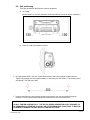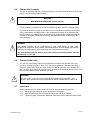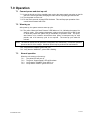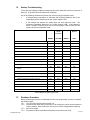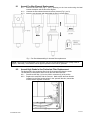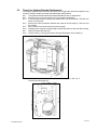
1
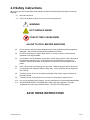
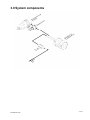
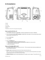
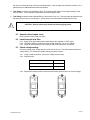
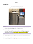
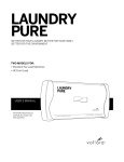
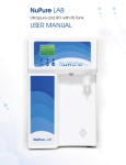
LABORATORY ZERO AIR GENERATOR ZAC-GC Series USER MANUAL 166 Keystone Drive Montgomeryville, PA 18936 Telephone: 215-641-2700 Fax: 215-641-2714 Email: [email protected] INT-0260-XX rev B Contents 1. Introduction ........................................................................................................................2 2. Safety instructions ..............................................................................................................3 3. System components...........................................................................................................4 4. Design overview .................................................................................................................5 5. Control board .....................................................................................................................6 6. Installation ..........................................................................................................................7 7. Operation .........................................................................................................................11 8. Maintenance.....................................................................................................................13 9. Troubleshooting Guide .....................................................................................................17 10. Specifications .................................................................................................................18 INT-0260-XX rev B 1 of 18 1.0 Introduction NOTICE: This manual is intended to provide technical guidance on the installation, operation and maintenance of the ZAC-GC series zero air generator. Do not attempt to install or operate this product without having fully read and understood the information presented. If you have questions, please contact Matheson Tri-Gas. WARNING: Any misuse of this product will void the manufacturer’s warranty. Product Description The ZAC-GC series zero air generator produces laboratory grade purified air for the most precise GC-FID equipment. Designed with safety and convenience in mind, this system will generate purified air from an existing in-house oil-free compressed air supply. The ZAC-GC series zero air generator will remove hydrocarbon pollutants to less than 0.1 ppm. Operation of the generator requires low levels of air consumption and electrical power. This complete turnkey system is engineered with the highest quality components, is easy to install, and requires only minimal annual maintenance. INT-0260-XX rev B 2 of 18 2.0 Safety instructions When using your zero air generator, basic safety precautions should always be followed, including the following: 2.1 Read all instructions. 2.2 Care must be taken as burns can occur from touching hot parts. ! WARNING HOT SURFACE INSIDE CONTACT MAY CAUSE BURN ALLOW TO COOL BEFORE SERVICING 2.3 Do not operate equipment with a damaged cord or if the equipment has been dropped or damaged – until it has been examined by a qualified serviceman. 2.4 Do not let cord hang over edge of table, bench, or counter or come in contact with hot manifolds or moving fan blades. 2.5 If an extension cord is necessary, a cord with a current rating equal to or more than that of the equipment should be used. Cords rated for less current than the equipment can overheat. Care should be taken to arrange the cord so that it will not be tripped over or pulled. 2.6 Never use the cord to pull the plug from the outlet. Grasp the plug and pull to disconnect. 2.7 Let equipment cool completely before putting away. Loop cord loosely around equipment when storing. 2.8 To reduce the risk of fire, do not operate equipment in the vicinity of open containers of flammable liquids. 2.9 To reduce the risk of electric shock, do not use on wet surfaces or expose to rain. 2.10 Use only as described in this manual. Use only manufacturer’s recommended attachments. 2.11 ALWAYS WEAR SAFETY GLASSES when working with this equipment. Everyday eyeglasses have only impact resistant lenses. They are NOT safety glasses. SAVE THESE INSTRUCTIONS INT-0260-XX rev B 3 of 18 3.0 System components INT-0260-XX rev B 4 of 18 4.0 Design overview The ZAC-GC series zero air generator utilizes a 3-stage process to purify ambient air into zero grade air. All main components are manufactured with high-grade stainless steel, oriented neatly in cabinet for easy access and service. 4.1 Stage 1: Prefiltration and Pressure Regulation 4.1.1 4.1.2 Air is initially passed through a highly efficient combination coalescing/particulate prefilter to ensure quality air enters the system. The pre-filter removes bulk moisture and larger particulates greater than 5 microns in size. The filter is supplied with an automatic float drain to remove periodic moisture build up. The air pressure is then regulated with a pressure regulator, pre-set to 100 psig (7 bar). The minimum allowable pressure is 65 psig (4.5 bar). 4.2 Stage 2: Hydrocarbon and CO Removal 4.2.1 Air is next channeled into a stainless steel catalyst chamber where any background hydrocarbons or carbon monoxide are oxidized. This chamber is filled with a highly efficient platinum catalyst, heated to very high temperatures to insure hydrocarbon removal to less than 0.1 ppm. 4.2.2 Catalyst temperature is a critical factor in the purification process. The temperature is monitored and controlled with a digital thermostat on the control board. A type K thermocouple is embedded in the catalyst chamber to provide the temperature measurement. Any time the catalyst temperature is outside of specified limits, appropriate LEDs are illuminated. 4.3 Stage 3: Final Filtration A final high-grade filter is used to remove 99.99% of particulates greater than 0.5 microns in size. This will insure that no harmful particles will be able to enter your gas analyzers during zero calibration. 4.4 Stage 4: Flow Regulation A flow regulator is used to limit maximum flow rate on the outlet. The setting cannot be changed by users. WARNING! DON’T ADJUST THE OUTLET FLOW REGULATOR 1 ADJUSTMENT OF THE OUTLET FLOW REGULATOR CAN DAMAGE THE UNIT ANY DAMAGE DONE TO THIS PRODUCT AS A RESULT OF IMPROPER MAINTENANCE PROCEDURES WILL VOID THE WARRANTEE. 2 INT-0260-XX rev B 5 of 18 5.0 Control board The control board performs the following functions: 5.1 Controls the warm up of the unit: the control board tells user if catalyst is warming up properly and when the catalyst has fully heated. 5.2 Monitors critical system parameters: the control board continuously checks for proper catalyst temperature to insure zero air purity specifications are always met. 5.3 Digital thermostat: the control board limits the maximum temperature to 650°C to preserve the life of the heating element. Without a thermostat, temperatures would often exceed this limit, especially if the air supply were interrupted. With the control board, you never have to worry about overheating. 5.4 Catalyst life alarm: the control board reminds you when the 3-year life of the catalyst is exceeded. After 3 years, the red external “check system” LED begins to flash. From this time, the operator has 60 days to replace the catalyst or the control board disables the system. 3 INT-0260-XX rev B 6 of 18 6.0 Installation 1 Air inlet 2 Air outlet 3 Inlet air filter 4 LED membrane 5 Door lock 4 Power button and fuse location for appropriate voltage setting. Items supplied with the unit: 1. Model ZAC-GC series zero air generator, completely assembled and is ready for installation; 2. One (1) high quality inlet air filter assembly is supplied with each system to remove particulates and bulk moisture before entering your unit; 3. One (1) power cord 4. Two (2) fuses 5. One (1) installation kit: 9 One (1) pipe nipple to attach your inlet filter to the unit 9 Two (2) machine screws with matching nuts and split lock washers to mount your unit 9 Two (2) door keys to lock your unit 9 One (1) user manual. Items not included with the unit: 1. Air supply shut-off valve placed upstream of the unit. This is required for safe and easy installation and for any needed maintenance. 2. Bleeder valve installed between the shut-off valve and the inlet of the unit. NOTE: The inlet air filter assembly supplied with your unit can also be used to de-pressurize your system by pushing the pin-valve in the base of the filter housing. 3. Additional filtration may be required depending on the quality of your air supply. The pre-filter of the unit INT-0260-XX rev B 7 of 18 will remove nominal amounts of moisture and particulates. If the air supply has excessive moisture, oil, or particulates, then additional filters should be installed. 4. Tube fitting to install to the supplied pre-filter. The exact type will depend on the supply tubing or hose from air source. A hose clamp is recommended if flexible tubing is used. 5. Tube fitting to install into the bulkhead fitting on the output of your unit. The exact type will depend on the transport tubing or hose to your analyzer. A hose clamp is recommended if flexible tubing is used. ! CAUTION: Remove plastic wrap inside unit before applying power. 6.1 Unpack unit and open cover. Remove plastic inlet & outlet port plugs. 6.2 Install external inlet filter. 6.2.1 Apply Teflon pipe sealant tape to both sides of the supplied 1/4" NPT nipple. 6.2.2 Thread the nipple to output side of the air filter assembly. Do not over tighten. 6.2.3 Attach air filter assembly to input side (left side) of the generator, and secure. 6.3 Check voltage setting. Check the setting of the voltage selector on the side of the unit. The white arrow indicates the voltage setting. To change the voltage setting, proceed as follows: 6.3.1 Using a small screwdriver, remove the voltage selector insert 6.3.2 Replace fuses: Voltage setting Fuse 240 Vac 4 AT 120 Vac 6 AT INT-0260-XX rev B 120 240 6.3.3 Replace the voltage selector insert so that the white arrow points to the correct voltage. 8 of 18 6.4 Unit positioning There are two different positions the units can be placed: a) On a table. (Allow at least 6 in (150 mm) clearance around the sides of the unit for proper ventilation.) b) Fixed on a wall or permanent structure. 9 Drill appropriate holes in the wall or permanent structure and insert supplied mounting screws. Tighten only enough so there is approximately 1/4” extruding from the surface. The mounting holes are spaced 7-7/8” (200 mm) apart. 9 Hold the generator up to the extruding screws, and insert the unit over the screws through the keyholes. Let the unit slide downward as the screws slide up into the keyhole slots. WARNING DO NOT TIGHTEN SCREWS FULLY. THE ZAC-GC SERIES GENERATOR IS NOT DESIGNED TO BE PERMANENTLY MOUNTED TO A WALL OR OTHER PERMANENT STRUCTURE. IT MUST BE POSSIBLE TO REMOVE THE UNIT WITHOUT THE USE OF TOOLS. INT-0260-XX rev B 9 of 18 6.5 Connect the air supply. The zero air generator requires a continuous supply of dry, compressed air between 65 and 145 psig (4.5 and 10 bar) for proper operation. WARNING ! MAXIMUM INLET PRESSURE 145 psig (10 Bar) The air pressure is regulated with an internal pressure regulator, pre-set to 100 psig (7 bar). It is important that the air supply be maintained at room temperature and dew point, and free of oils, hydrocarbons, and particulates. If the compressed air supply for the generator has excess moisture, oil, or particulates, the inlet filter may need premature replacement and the unit may be damaged. Install extra coalescing and particulate filtration upstream from the unit if necessary. WARNING The catalyst chamber can be contaminated by high concentrations of lead, sulfur, phosphorous compounds, heavy metals, chlorinated solvents, and chlorinated hydrocarbons. Extra care should be taken to avoid introducing such compounds to the system. ! Any contamination from oil, water or any of the substances mentioned above will void the warranty on your unit. 6.6 9 9 Connect to the outlet The 1/8" FPT output fitting of the zero air generator is located on the right side of the unit. In order to maintain the purity of the air from your zero air generator, stainless steel tubing or instrument grade Teflon tubing should be used to connect the generator to the analyzer zero port. All plastic hose should be instrument grade and free of contaminants, so that it will not outgas any hydrocarbons or other pollutants over time. WARNING ! 6.7 Do not use PVC or any other non-instrument grade plastic tubing anywhere in your system. Many plastics will out-gas hydrocarbons and will contaminate your purified air. Leak check Before powering the unit, perform a leak check on the external plumbing to the unit. 6.7.1 6.7.2 6.7.3 INT-0260-XX rev B Slowly open the supply air valve to pressurize to the system. Apply a leak test solution to all external fittings and look for air bubbles. Tighten any leaky connections. Additional Teflon tape may be required in some cases. 10 of 18 7.0 Operation 7.1 Connect power and start up unit 7.1.1 Insert the female end of the supplied power cord to the power supply connection on the left side of the zero air generator, and plug the male end into a properly grounded socket. 7.1.2 Turn the power on to the unit. 7.1.3 For the first 3 seconds, all panel LEDs illuminate. This verifies proper operation of the control board firmware and LEDs. 7.2 Warming up After power-up, the system enters a warm-up cycle. 7.2.1 The yellow “Warm-up/Check Pressure” LED flashes at 1 Hz, indicating the system is in warm-up mode. If the catalyst temperature is above the minimum level of 485°C and no faults are present the system will go immediately to operation mode. This quickstart feature is for customer convenience when power is interrupted only for brief periods, and a full warm-up cycle is not required. The warm-up cycle takes 50 minutes. NOTE: The ZAC-GC series zero air generator is designed to run continuously. Continuous operation preserves the life of the catalyst. Shutdown should only be performed for maintenance. 7.2.2 Verify that the “POWER” green LED is on. 7.2.3 Verify that the “WARM UP” yellow LED is flashing. 7.3 Normal operation When the unit comes out of warm up: 7.3.1 7.3.2 7.3.3 7.3.4 INT-0260-XX rev B The yellow LED will turn off. The green “System Ready” LED will illuminate. Verify that the “POWER” green LED is on. Verify that the “READY” green LED is on. 11 of 18 7.4 Startup Troubleshooting If there are any improper conditions detected by the control board the unit will not come out of warm up. The panel LEDs will indicate fault conditions. Any of the following conditions will prevent the unit from going to operation mode: • If catalyst heater temperature is still below the minimum threshold, then a low temperature fault is indicated by the red “Check System” LED; • If the catalyst has expired, the system does not enter warm-up mode. The processor immediately flashes the red “Check System” LED. If the catalyst is within 2 months of expiring, then the red “Check System” LED will flash, but the system will still enter operation mode. Condition System Off Power Warmup/ Check Pressure Ready Check System GREEN YELLOW GREEN RED OFF OFF OFF OFF Blink 1 Hz Blink 1 Hz Blink 1 Hz Blink 1 Hz OFF OFF OFF OFF Blink 1 Hz OFF OFF Start-up System check ( 3 seconds) System fault Quickstart Mode System check (5 seconds) ON Blink 1 Hz OFF OFF Ready ON OFF ON OFF OFF OFF Warm-up Warm-up (50 minutes) ON Blink 1 Hz Fault: catalyst temperature below set point (after 20 min) ON OFF OFF ON ON OFF ON OFF Catalyst temperature exceeds set point ON OFF OFF ON Catalyst temperature below set point ON OFF OFF ON After 3 years ON ON ON (1) Blink 1 Hz After 3 years and 2 months ON ON OFF ON Operation Ready General system fault conditions Catalyst replacement Control Board Program Logic Table 7.5 Shutdown Procedure Before performing any service or maintenance to the zero air generator, be sure to complete the following steps: 7.5.1 Turn off power using the switch on the unit. 7.5.2 Disconnect the outlet tubing, and freely run air through the unit for several minutes to cool the catalyst. Allow a minimum of 2 hours to cool the catalyst before replacing. 7.5.3 Shut off air supply. 7.5.4 De-pressurize the unit and disconnect power source before servicing. INT-0260-XX rev B 12 of 18 8.0 Maintenance WARNING: ! Before service is performed, make certain that the following conditions are met: 1. System shut down has been performed according to instructions above. 2. Supply pressure has been shut off. 3. Line pressure has been released. 4. Unit has been shut-off and isolated from electrical power. Annual Maintenance Kits The ZAC-GC series zero air generator is designed to operate continuously for an entire year before service is required. An annual maintenance kit will be available as spare part. This kit will include all required parts. Specifically, each kit will include: 1. New pre-filter element (ZAC-EXT-CART). 2. New high-grade particulate final filtration (ZAC-INT-CART). 3-year Catalyst Replacement Kits A catalyst kit will also be available as spare part for its 3-year replacement. The catalyst must be replaced every 3 years to insure the removal of CO and HC to 0.1 ppm levels. WARNING ! ONLY QUALIFIED PERSONNEL SHOULD PERFORM SERVICE ON THIS PRODUCT. ANY DAMAGE DONE TO THIS PRODUCT AS A RESULT OF IMPROPER MAINTENANCE PROCEDURES WILL VOID THE WARRANTY. INT-0260-XX rev B 13 of 18 8.1 Annual Pre-filter Element Replacement 8.1.1 8.1.2 8.1.3 Remove the filter bowl (Fig. 1, pos.1) pressing on the lever and turning the bowl counter-clockwise until the arrow are aligned. Unscrew the filter element base and remove element (Fig.1, pos 3). Insert the new element and reassemble the filter in reverse order. Fig. 1: Pre-filter disassembling for element filter replacement. NOTE: More frequent replacement of the inlet filter may be required depending on the quality of the air supply. Alternately, more filtration can be applied upstream of the zero air generator. 8.2 Annual High Grade In-line Particulate Filter Replacement The high-grade in-line particulate filter is the final component before the outlet. The filter body is clear plastic and is held by the inlet and outlet lines. 8.2.1 Disconnect the filter (1) from the push-in connector (2) of the air line. 8.2.2 Replace the used filter with the new one. Make certain the flow direction indicated on the filter housing points in the “upward” direction, toward the outlet pressure regulator on the unit. INT-0260-XX rev B 14 of 18 8.3 Three Year Catalyst Chamber Replacement: The catalyst chamber used in the ZAC-GC series zero air generator should be replaced every 3 years to maintain carbon monoxide and hydrocarbon specifications. 8.3.1 The system should be shut down as described above prior to replacement. 8.3.2 Allow the unit to cool for a minimum of 2 hours before replacement. 8.3.3 If unit has been powered recently and catalyst is hot, turn off the power. DO NOT turn off the air at this time. 8.3.4 Remove the outlet connection and allow the outlet air to flow freely for 2 hours to cool the catalyst. 8.3.5 After 2 hours of cool-down, disconnect the air supply. 8.3.6 Depressurize the system by depressing the pin at the bottom of the inlet filter housing. 8.3.7 Open front panel with door key. 8.3.8 Loosen screws (1) and (2) and remove the right side plastic cover screws (3) 8.3.9 INT-0260-XX rev B Carefully disconnect the two compression air fittings (1) and (2) to remove the cooling spiral (3). 15 of 18 8.3.10 Remove the heater and thermocouple wires from the control board and the ground wire from the oven. 8.3.11 Unscrew the two screws to remove the aluminum plate from the metal heat shield covering the catalyst chamber. 8.3.12 When the catalyst chamber is cool to the touch, extract the catalyst chamber from the unit. 8.3.13 Install the new catalyst chamber assembly using the reverse process. 8.3.14 Connect the heater and thermocouple wires to the control board and connect the ground wire to the oven. 8.3.15 Pressurize the system and check thoroughly for leaks. INT-0260-XX rev B 16 of 18 9.0 Troubleshooting Guide 1. Fault table. Condition Power Warmup/ Check Pressure Ready Check System GREEN YELLOW GREEN RED Start-up OFF OFF OFF OFF ON OFF OFF ON Catalyst temperature exceeds set point ON OFF OFF ON Catalyst temperature below set point ON OFF OFF ON System fault Warm-up Fault: catalyst temperature below set point (after 20 min) General system fault conditions Catalyst replacement After 3 years ON ON ON (1) Blink 1 Hz After 3 years and 2 months ON ON OFF ON System can be reset to initial condition: Turn off unit to reset system. Turn on unit and check for LED configuration. 2. Leaks. Apply leak-check solution to all external fittings and look for air bubbles. Tighten any leaky connections. Additional Teflon tape may be required in some cases. INT-0260-XX rev B 17 of 18 10 Specifications Outlet Hydrocarbon Concentration Outlet Carbon Monoxide Concentration Outlet Particles < 0.5 microns removed Outlet Air Temperature Max Inlet Hydrocarbon Concentration Max Inlet Carbon Monoxide Concentration Max Inlet Temperature Inlet Pressure Range (regulated to 100 psig (7 bar)) Pressure Drop @ max Flow Rate Maximum Outlet Pressure Startup Time for Specified THC Concentration Inlet Port Outlet Port < 0.1 ppm < 0.1 ppm 99.99% Ambient + 27 °F (15 °C) 100 ppm 50 ppm 104 °F (40 °C) 65-145 psig (4.5 -10 bar) 15 psig (1 bar) 94 psig (6.5 bar) 50 minutes 1/4" FPT 1/8" FPT Electrical Requirements System Dimensions (H x W x D) 115/230 VAC 16” x 18.5” x 10” (41 x 47 x 25 cm) <25 lbs (11 kg) Generator Weight INT-0260-XX rev B 18 of 18