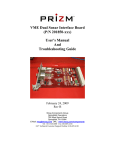
1
MM2/Mini4 10/100 Ethernet Daughterboard
(P/N 201750-xxx)
User’s Manual
And
Troubleshooting Guide
February 24, 2009
Revision B
Moog Components Group
Springfield Operations
750 West Sproul Road
Springfield, PA 19064
E-Mail: [email protected] URL: www.moog.com/components
Tel: 610-328-4000 Fax 610-605-6216
24/7 Technical Customer Support Hotline: 610-605-6101
Moog Components Group
201750-xxx MM2/Mini4 10/100
Ethernet Daughterboard Manual, Rev B
Feb 24, 2009
MANUAL REVISION HISTORY
REVISION
DATE
BY
NUMBER
REASON FOR
REVISION
A
5/2/07
GSG
ORIGINAL
B
2/24/09
IB
Updated contact information to reflect
Moog Components Group
TABLE OF CONTENTS
MM2/MINI4 10/100 ETHERNET DAUGHTERBOARD, P/N: 201750-XXX ............................... 3
1
1.1
1.2
1.3
1.4
1.5
1.6
1.7
1.8
10/100 ETHERNET INTERFACE:........................................................................................................ 3
MM2/MINI4 10/100 ETHERNET DAUGHTERBOARD REVISION HISTORY: ........................................ 4
MM2/MINI4 10/100 ETHERNET DAUGHTERBOARD DASH (-) NUMBER DEFINITIONS ...................... 4
MM2/MINI4 10/100 ETHERNET DAUGHTERBOARD OPERATION: .................................................... 4
10/100 ETHERNET INTERFACE DAUGHTERBOARD INDICATORS AND CONTROLS:............................ 4
MM2/MINI4 10/100 ETHERNET DAUGHTERBOARD SPECIFICATIONS:............................................. 7
MM2/MINI4 10/100 ETHERNET DAUGHTERBOARD POWER REQUIREMENTS: ................................. 8
MM2/MINI4 10/100 ETHERNET DAUGHTERBOARD DIMENSIONS: .................................................. 8
Page 2 of 8
Moog Components Group
1
201750-xxx MM2/Mini4 10/100
Ethernet Daughterboard Manual, Rev B
Feb 24, 2009
MM2/Mini4 10/100 Ethernet Daughterboard, P/N: 201750-xxx
The Prizm MM2/Mini4 10/100 Ethernet daughterboard combines the functionality of a fourport 10/100 Ethernet switch and a high speed synchronous Ethernet to serial bridge to
provide an end-to-end Ethernet link over a fiber multiplexer. This board must be stacked
onto a MM2 or a Mini4 motherboard set.
The board contains no user-modifiable jumper selections for this board. All functions are
handled automatically.
1.1 10/100 Ethernet Interface:
The 10/100 Ethernet daughterboard automatically supports both 10 and 100Mbps Ethernet
on each of the 4 switch ports. Mixed port-to-port Ethernet rates are supported and rate
adaptation is handled automatically. The 5th port on the switch connects to the synchronous
Ethernet to serial bridge chip. This chip buffers the Ethernet packets and flows the packets
serially through the MM2/Mini4 daughterboard connector at a synchronous data rated
defined by the MM2 (16Mbps) or Mini4 (25Mbps).
The 100Mbps Ethernet data rate is approximately 4 times the daughterboard throughput
capacity of the MM2 and Mini4. Therefore there will be some degradation to the Ethernet
traffic throughput over the MM2 or Mini4. At the 10Mbps Ethernet rate there should be
little throughput degradation.
Testing by Prizm has determined the following end-to-end throughput rates:
MM2 or Mini4
MM2
MM2
Mini4
Mini4
Ethernet Rate
10Mbps
100Mbps
10Mbps
100Mbps
Throughput
8Mbps
15Mbps
20Mbps
25Mbps
Ethernet throughput is typically defined as the number of bits in a ping packet divided by the
round-trip time that a ping packet takes to get from the originating PC to the target PC and
back again. As this is a round-trip measurement, the ping packet bit size is doubled for this
computation.
For example from table above:
1. Size of ping packet = 15766 bytes * 8 = 126,128 bits per packet
2. Round-trip time = 17.05 milliseconds
Throughput = Size of ping packet * 2 / Round-trip time
= (126,128 * 2) / 0.01705
= 14,795,073 bps
= 14.79Mbps
Page 3 of 8
Moog Components Group
201750-xxx MM2/Mini4 10/100
Ethernet Daughterboard Manual, Rev B
Feb 24, 2009
1.2 MM2/Mini4 10/100 Ethernet Daughterboard Revision History:
The MM2/Mini4 10/100 Ethernet daughterboard has gone through the following printed
circuit board (PCB) and Assembly revisions:
PCB Revision A
PCB Revision B
Original design.
Various circuit and routing corrections.
1.3 MM2/Mini4 10/100 Ethernet Daughterboard Dash (-) Number
Definitions
The MM2/Mini4 10/100 Ethernet daughterboard has a Dash Number appended to the part
number. This Dash Number identifies the specific board configurations:
-001A // -001A PT
-001B // -001A PT
-002B
Original configuration, obsolete
Rev B PCB, no LED display header placed
Rev B PCB, LED display header placed for Surface
1.4 MM2/Mini4 10/100 Ethernet Daughterboard Operation:
Each of the four 10/100 Ethernet ports automatically switch to follow the PC attached to the
specific port. There are two LEDs located within the quad RJ-45 connector. The left LED
(green) will be lit if the port is running at 100Mbps and will be off if 10Mbps. The right
LED (yellow) will be lit solidly if an Ethernet link is detected and blink off with traffic. All
four ports are also auto-polarity correcting so either straight or crossover cables can be used.
NOTE 1: Two DIP-socketed EEPROMs (at U15/20 and U12/13) must be placed for
this board to function correctly.
1.5 10/100 Ethernet Interface Daughterboard Indicators and
Controls:
LEDS:
There are 13 surface mount vertical LED indicators on the top of the board and 1 surface
mount LED indicators on the bottom of the board.
Top of Board
LED
Indication
D1 (Green)
Labeled ‘DB PWR’, Located at the upper left of the board serves as an indicator that +5VDC
is available to the board. Supply voltage to the board is selected via the placement of fuse F6
from the Daughterboard Header (J1), F7 from the Diagnostics Header (J2), or F3 from the
Auxiliary daughterboard header (J4).
D2 (Green)
Labeled ‘TX DATA’, located at the center right edge of the board serves as an indicator the
diagnostics data is being transmitted out of the board on the Diagnostics Header (J4) or
Diagnostics connector (J6). NOTE: DIAGNOSTICS NOT AVAILABLE
D3 (Green)
Labeled ‘RX DATA’, located at the center right edge of the board serves as an indicator the
diagnostics data is being received into the board on the Diagnostics Header (J4) or
Page 4 of 8
Moog Components Group
201750-xxx MM2/Mini4 10/100
Ethernet Daughterboard Manual, Rev B
Feb 24, 2009
Diagnostics connector (J6). NOTE: DIAGNOSTICS NOT AVAILABLE
D4 (Green)
Located at the lower right edge of the board serves as an indicator that the microprocessor is
receiving diagnostics requests from the diagnostics PC through the Diagnostics Header (J4)
or Diagnostics connector (J6). This LED will blink ON with a received request then OFF
with the next request. NOTE: DIAGNOSTICS NOT AVAILABLE
D5 (Green)
Labeled ‘Q_OF’, located on the center top edge of the board, if “OFF” provides an indication
that the Ethernet to serial chip U8 is overflowing its internal buffer. Typically this LED will
always be “ON” – not in an error state.
D6 (Green)
Labeled ‘LOCAL’, located on the center top edge of the board, if “ON” provides an
indication that the programmable logic device U1 is receiving a system receive clock and
receiving data from the Daughterboard Header (J2).
D7 (Green)
Labeled ‘REMOTE’, located on the center top edge of the board, if “ON” provides an
indication that the programmable logic device U1 is receiving a system transmit clock and
outputting data onto the Daughterboard Header (J2).
D9 (Green)
Labeled ‘+3.3V’, located at the bottom right edge of the board serves as an indicator that the
on-board +3.3VDC power supply (U6) is working.
D10 (Green)
Labeled ‘W_TX’, located on the center top edge of the board, if “ON” provides an indication
that the programmable logic device U1 is receiving data from the Ethernet to serial chip (U8)
and outputting data onto the Daughterboard Header (J2).
D11 (Green)
Labeled ‘W_RX’, located on the center top edge of the board, if “ON” provides an indication
that the programmable logic device U1 is receiving data from the Daughterboard Header (J2)
and sending it to the Ethernet to serial chip (U8).
D12 (Green)
Labeled “P5 LED1”, located at the lower right edge of the board serves as an indicator that
data is being sent between the Ethernet Switch chip (U4) and the Ethernet to serial chip (U8).
NOTE: THIS FUNCTION IS NOT AVAILABLE
D13 (Green)
Labeled “P5 LED2”, located at the lower right edge of the board serves as an indicator that
data is being sent between the Ethernet Switch chip (U4) and the Ethernet to serial chip (U8).
NOTE: THIS FUNCTION IS NOT AVAILABLE
D14 (Green)
Labeled “P5 LED3”, located at the lower right edge of the board serves as an indicator that
data is being sent between the Ethernet Switch chip (U4) and the Ethernet to serial chip (U8).
NOTE: THIS FUNCTION IS NOT AVAILABLE
Bottom of Board
LED
Indication
D8 (Green)
Located at the bottom left edge of the board serves as an indicator that the LED display
header is powered.
CONNECTORS AND HEADERS:
J1
ISP Header
Page 5 of 8
Moog Components Group
201750-xxx MM2/Mini4 10/100
Ethernet Daughterboard Manual, Rev B
+3.3V
TCK
N/C
GND
1
3
5
7
o
o
o
o
o
o
o
o
2
4
6
8
TMS
TDI
TDO
o
o
o
o
o
o
2
4
6
8
10
12
VDC Supply
TXD_DB
GND
TXC_DB
Future
TXD_DB2
o
o
o
o
o
o
o
o
o
o
o
o
o
o
o
o
o
2
4
6
8
10
12
14
16
18
20
22
24
26
28
30
32
34
PTC FUSE with +5VDC
REMOTE_LED
WAN_TX_LED
SPEED_P1_LED
SPEED_P2_LED
SPEED_P3_LED
SPEED_P4_LED
NO CONNECT
NO CONNECT
NO CONNECT
NO CONNECT
NO CONNECT
NO CONNECT
NO CONNECT
NO CONNECT
NO CONNECT
NO CONNECT
NOTE: J1 to be used only by PRIZM.
J2
Daughterboard Header
VDC Supply
RXD_DB
GND
RXC_DB
RCV LINK
RXD_DB2
J3
1
3
5
7
9
11
o
o
o
o
o
o
Led Status Connector
GND
LOCAL_LED
WAN_RX_LED
ACT_P1_LED
ACT_P2_LED
ACT_P3_LED
ACT_P4_LED
NO CONNECT
NO CONNECT
NO CONNECT
NO CONNECT
NO CONNECT
NO CONNECT
NO CONNECT
NO CONNECT
NO CONNECT
NO CONNECT
1
3
5
7
9
11
13
15
17
19
21
23
25
27
29
31
33
o
o
o
o
o
o
o
o
o
o
o
o
o
o
o
o
o
NOTE 1: J3 header is located at the top center side of the board.
Pin 1 is the lower left pin – as identified by a square pad.
NOTE : Signals are active low.
J4
Diagnostics Header
RT+
GND
GND
+5V
+5V
J5
1
3
5
7
9
o
o
o
o
o
o
o
o
o
o
2
4
6
8
10
RTGND
GND
+5V
+5V
Quad RJ-45 Connector
Ethernet Port 1
Ethernet Port 2
Ethernet Port 3
1
2
3
Page 6 of 8
Feb 24, 2009
Moog Components Group
201750-xxx MM2/Mini4 10/100
Ethernet Daughterboard Manual, Rev B
Ethernet Port 4
Feb 24, 2009
4
Diagnostics Connector
J6
o 1
o 2
o 3
RT+
GND
RT-
FUSES:
There are three fuses for this board,
F1:
1.5 Amp PTC, +5VDC input fuse for “DIAG HEADER” header at J4
- DO NOT PLACE
F2:
1.5 Amp PTC, +5VDC input fuse for Daughterboard header at J2
F3:
1.5 Amp PTC, +5VDC output fuse for LED header at J12
- DO NOT PLACE
SWITCHES:
There are no switches on this board.
TRIMPOTS:
There no trimpots on this board.
JUMPER POSTS:
JP1, 2, 3, 4:
Switch (U4) configuration select – DO NOT CHANGE
JP1:
1o
o 2
PS1
JP2:
1o
o 2
PS0
JP3:
1 o==o 2
SCONF0
JP4:
1o
SCONF1
o 2
1.6 MM2/Mini4 10/100 Ethernet Daughterboard Specifications:
Number of Ports:
Data rates supported:
Connector:
4
10 or 100Mbps
Quad RJ-45
Page 7 of 8
Moog Components Group
201750-xxx MM2/Mini4 10/100
Ethernet Daughterboard Manual, Rev B
Feb 24, 2009
1.7 MM2/Mini4 10/100 Ethernet Daughterboard Power
Requirements:
The 10/100 Ethernet daughterboard uses approximately 330mA @ 5VDC.
1.8 MM2/Mini4 10/100 Ethernet Daughterboard Dimensions:
PC/104 format - 95.8 mm wide x 90.17 mm long x 13 mm thick
(3.775 in x 3.550 in x 0.50 in )
Page 8 of 8