1
Accessory 24C2A
PINOUT DESCRIPTION
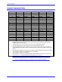
P2 Connector
Row
A
B
C
D
E
22
DACA1+
DACA2+
A+12/15V
DACA3+
DACA4+
21
DACA1DACA2AGND
DACA3DACA420
DACB1+
DACB2+
A-12/15V
DACB3+
DACB4+
19
DACB1DACB2AGND
DACB3DACB418
AENA1+
AENA2+
AENARET
AENA3+
AENA4+
17
FAULT1
FAULT2
FAULTRET
FAULT3
FAULT4
16
FRET1
FRET2
ADCA1
FRET3
FRET4
15
HOME1
HOME2
ADCB1
HOME3
HOME4
14
PLIM1
PLIM2
ADCA2
PLIM3
PLIM4
13
MLIM1
MLIM2
ADCB2
MLIM3
MLIM4
12
USER1
USER2
ADCA3
USER3
USER4
11
DIR1+/U1
DIR2+/U2
ADCB3
DIR3+/U3
DIR4+/U4
10
DIR1-/V1
DIR2-/V2
ADCA4
DIR3-/V3
DIR4-/V4
9
PUL1+/W1
PUL2+/W2
ADCB4
PUL3+/W3
PUL4+/W4
8
PUL1-/T1
PUL2-/T2
GND
PUL3-/T3
PUL4-/T4
7
EQU1
EQU2
GND
EQU3
EQU4
6
ENCC1+
ENCC2+
GND
ENCC3+
ENCC4+
5
ENCC1ENCC2GND
ENCC3ENCC44
ENCB1+
ENCB2+
+5V
ENCB3+
ENCB4+
3
ENCB1ENCB2+5V
ENCB3ENCB42
ENCA1+
ENCA2+
+5V
ENCA3+
ENCA4+
1
ENCA1ENCA2+5V
ENCA3ENCA4Notes:
1. Signals in Rows 19 to 22, and ADC pins, are referenced to AGND (analog ground), optically
isolated from the digital circuits.
2. Signals in Rows 1 to 11 (except ADCs) are referenced to GND (digital ground).
3. The signal AENARET is the return signal for the 4 isolated AENAn outputs.
4. Each signal FRETn is the return signal for optically isolated sinking/sourcing inputs HOMEn,
PLIMn, MLIMn, and USERn. Each set of these 4 inputs is isolated from all other circuits on the
board.
5. The signal FAULTRET is the return for the 4 optically isolated sinking/sourcing FAULTn inputs.
These inputs will typically be ultimately referenced to AGND.
6. Outer columns Z and F are all shield pins.
7. Each channel has a jumper to permit the output of Pulse and Direction signals on what would
otherwise be T, U, V, and W supplementary input flags (rows 12 to 15).
Note:
Row 22 is physically the top row with the cards in normal orientation.
Pinout Description
29