1
MULTIFUNCTION GENERATOR
WF1973/WF1974
Instruction Manual (Basics)
NF Corporation
DA00016809-001
MULTIFUNCTION GENERATOR
WF1973/WF1974
Instruction Manual (Basics)
Preface
Thank you for purchasing the WF1973/WF1974 Multifunction Generator.
To ensure safe and proper use of this electric equipment, please read first Safety Precautions on
the following pages.
●Caution Symbols Used in This Manual
The following caution symbols are used in this manual. Be sure to observe these caution
symbols and their contents to ensure the safety of the user and avoid damage to the
equipment.
WARNING This mark indicates information for the avoidance of a hazard such as electric
shock that may endanger human life or cause injury during handling of the
equipment.
CAUTION
This mark indicates information for the avoidance of damage to the equipment
during handling.
●This manual has the following chapter organization.
Instruction manuals of the WF1973/WF1974 are divided to two volumes, Basics and
Application. Instructions for remote control (GPIB and USB) are provided separately.
If reading this manual for the first time, start from 1. OVERVIEW of the Basics Instruction
Manual.
Basics
1. OVERVIEW
Briefly describes and explains the features and brief operation principles of the WF1973/
WF1974.
2. PREPARATIONS BEFORE USE
Describes various cautions regarding preparations to be made before using the WF1973/
WF1974, ranging from installation to connection of the power supply.
3. PANELS AND I/O TERMINALS
Describes the functions and operations of the switches and I/O terminals of the panel
controls.
4. BASIC OPERATION
Describes how to use basic functions.
5. SAVING AND RECALLING SETTINGS
Describes how to store and retrieve the settings.
6. LIST OF INITIAL SETTINGS
Describes initial settings.
7. SPECIFICATIONS
Lists the specifications (functions and performance) of the WF1973/WF1974.
Application
1. DETAILS OF PARAMETER-VARIABLE WAVEFORMS
Explains the meanings of each parameter of parameter-variable waveforms and
waveform examples.
2. CREATING ARBITRARY WAVEFORMS
Explains how to input and edit arbitrary waveforms from the panel control.
WF1973/WF1974
I
3. HANDY USE OF 2-CHANNEL DEVICE (WF1974 ONLY)
Explains how to operate two channels at the same time.
4. SYNCHRONIZING MULTIPLE UNITS
Describes how to configure a multi-phase oscillator by connecting multiple units of this
product.
5. USING EXTERNAL FREQUENCY REFERENCE
Describes how to use external frequency reference.
6. USING SEQUENCE OSCILLATION
Describes how to set and operate sequence oscillation.
7. USING USER-DEFINED UNITS
Explains the units that can be optionally set by users.
8. OTHER UTILITY SETTINGS
Explains how to set display and operational details.
9. TROUBLESHOOTING
Explains error messages and how to respond to cases where a failure is suspected.
10. MAINTENANCE
Explains the operational inspection and performance test.
II
MULTIFUNCTION GENERATOR
Safety Precautions
To ensure safe use, be sure to observe the following warnings and cautions.
NF Corporation shall not be held liable for damages that arise from a failure to observe these
warnings and cautions.
This product is a Class I product (with protective conductor terminal) that conforms to the JIS and
IEC insulation standards.
●Be sure to observe the contents of this instruction manual.
This instruction manual contains information for the safe operation and use of this product.
Be sure to read this information first before using this product.
All the warnings in the instruction manual must be heeded to prevent hazards that may
cause major accidents.
●Be sure to ground the product.
This product uses a line filter and must be grounded to avoid the risk of electric shock.
To prevent electric shock, be sure to safely implement grounding such that ground resistance is 100 Ω or lower.
The WF1973/WF1974 is automatically grounded when the 3-prong power plug is connected
to a 3-prong power outlet with a protective grounding contact.
This product does not come with a 3-prong to 2-prong conversion adapter. When using a
separately sold 3-prong to 2-prong conversion adapter, be sure to connect the (green)
grounding wire of the adapter to the grounding terminal next to the outlet.
●Check the power supply voltage.
This product operates on the power supply voltage shown in 2.3 Grounding and Power
Supply Connection in the Basics Instruction Manual.
Prior to connecting the power supply, check that the voltage of the power supply matches
the rated power supply of the product.
●In case of suspected anomaly
If this product emits smoke, an abnormal smell, or abnormal noise, immediately power it off
and stop using it.
If such an anomaly occurs, do not use this product until it has been repaired, and
immediately report the problem to the location of purchase (either NF Corporation or your
distributor).
●Do not use this product when gas is present.
An explosion or other such hazard may result.
●Do not remove the cover.
This product contains high-voltage parts. Absolutely never remove its cover.
Even when the inside of this product needs to be inspected, do not touch the inside. All such
inspections are to be performed by service technicians designated by NF Corporation.
●Do not modify this product.
Absolutely never modify this product, as this may cause new hazards and may disqualify
this product from repair in case of failure.
WF1973/WF1974
III
●Safety-related symbols
The general definitions of the safety-related symbols used on this product and in the
instruction manual are provided below.
Instruction Manual Reference Symbol
This symbol is displayed to alert the user to potential danger and refer
him/her to the instruction manual.
Electric Shock Danger Symbol
This symbol indicates locations that present a risk of electric shock under
specific conditions.
WARNING Warning Symbol
This symbol indicates information for avoiding danger to human life or
bodily injury while handling this product.
CAUTION
Caution Symbol
This symbol indicates information for preventing damage to the product
when handling it.
●Other symbols
This symbol indicates that the external conductor of the connector is
connected to the case.
This symbol shows that the external
insulated from the case.
It shows, however, that the potential
potential is restricted to 42 Vpk or lower
grounded when used, the potential of
potential.)
conductor of the connector is
difference from the grounding
for safety. (Since this product is
the case equals the grounding
●Waste disposal
To help ensure environmental protection, use a professional industrial waste contractor to
dispose of this product. A battery is not used for this product.
IV
MULTIFUNCTION GENERATOR
Contents
Preface .................................................................................................................I
Safety Precautions..............................................................................................III
Contents ............................................................................................................. V
Figures and Tables .......................................................................................... VIII
1. OVERVIEW ....................................................................................................1
1.1 Features............................................................................................................. 1
1.2 Operating Principles .......................................................................................... 2
2. PREPARATIONS BEFORE USE ...................................................................4
2.1 Checking Before Use......................................................................................... 4
2.2 Installation.......................................................................................................... 5
2.3 Grounding and Power Supply Connection......................................................... 6
2.4 Calibration.......................................................................................................... 7
3. PANELS AND I/O TERMINALS......................................................................8
3.1 Panel Components and Operations................................................................... 8
3.1.1 Front panel of WF1973 .............................................................................. 8
3.1.2 Rear panel of WF1973 ............................................................................... 9
3.1.3 Front panel of WF1974 ............................................................................ 10
3.1.4 Rear panel of WF1974 ............................................................................. 11
3.2 I/O Terminals ................................................................................................... 12
3.2.1 Waveform output (FCTN OUT) ................................................................ 12
3.2.2 Sync/sub-output (SYNC/SUB OUT)......................................................... 13
3.2.3 External modulation/addition input (MOD/ADD IN) .................................. 14
3.2.4 External trigger input (TRIG IN) ............................................................... 14
3.2.5 External 10 MHz frequency reference input (10 MHz REF IN) ................ 15
3.2.6 Frequency reference output (REF OUT).................................................. 16
3.2.7 Multi-I/O (MULTI I/O)................................................................................ 16
3.3 Cautions on Floating Ground Connection........................................................ 19
4. BASIC OPERATION.....................................................................................21
4.1 Power on/off Switching and Restoration of Settings........................................ 21
4.1.1 Power on/off switching method ................................................................ 21
4.1.2 Restoration of settings at power-on ......................................................... 22
4.2 Screen Configuration and Operation .............................................................. 25
4.2.1 Screen configuration ................................................................................ 25
4.2.2 Switching display format with tabs (displaying waveform graph) ............. 27
4.2.3 Top menu ................................................................................................. 29
4.3 Basic Settings and Operations ........................................................................ 30
WF1973/WF1974
V
4.3.1 Changing the frequency, amplitude, and other values............................. 30
4.3.2 Changing the waveform and oscillation mode ......................................... 33
4.3.3 Manipulating shortcut keys for changing basic parameters ..................... 34
4.3.4 Operations of ENTER key, CANCEL key, and UNDO key ..................... 35
4.3.5 Changing the display unit......................................................................... 36
4.3.6 CH1/CH2 switching key and active channel (WF1974 only).................... 38
4.3.7 Actions possible in the Utility screen........................................................ 39
4.3.8 Restoring the initial settings ..................................................................... 41
4.3.9 Output on/off ............................................................................................ 41
4.4 Setting Methods for Main Items ....................................................................... 43
4.4.1 Configuration of text display screen in continuous oscillation mode ........ 43
4.4.2 Setting the oscillation mode ..................................................................... 43
4.4.3 Setting the waveform ............................................................................... 44
4.4.4 Setting the frequency ............................................................................... 44
4.4.5 Performing setting with period.................................................................. 45
4.4.6 Setting the phase ..................................................................................... 45
4.4.7 Setting the amplitude ............................................................................... 48
4.4.8 Setting DC offset ...................................................................................... 50
4.4.9 Setting the output level with high level/low level ...................................... 51
4.4.10 Setting the waveform polarity and amplitude range ............................... 52
4.4.11 How to use auto range/range hold for the output voltage ...................... 54
4.4.12 Setting the load impedance.................................................................... 55
4.4.13 Adding external signal............................................................................ 57
4.4.14 Setting the square wave duty................................................................. 59
4.4.15 Setting the pulse width and leading/trailing edge time of a pulse wave . 61
4.4.16 Setting the ramp wave symmetry........................................................... 64
4.5 Using Parameter-Variable Waveforms ............................................................ 65
4.6 Using Arbitrary Waveforms.............................................................................. 67
4.7 Modulation Setting and Manipulation............................................................... 69
4.7.1 Modulation types ...................................................................................... 69
4.7.2 Screen for modulation setting and manipulation ...................................... 70
4.7.3 Common modulation settings and manipulations .................................... 72
4.7.4 Setting FM................................................................................................ 75
4.7.5 Setting FSK .............................................................................................. 76
4.7.6 Setting PM................................................................................................ 77
4.7.7 Setting PSK.............................................................................................. 78
4.7.8 Setting AM................................................................................................ 79
4.7.9 Setting AM (DSB-SC)............................................................................... 80
4.7.10 Setting DC offset modulation ................................................................. 81
4.7.11 Setting PWM .......................................................................................... 82
4.8 Sweep Setting and Manipulation ..................................................................... 83
4.8.1 Sweep types............................................................................................. 83
4.8.2 Screen for sweep setting and manipulation ............................................. 83
VI
MULTIFUNCTION GENERATOR
4.8.3 Common sweep settings and manipulations............................................ 86
4.8.4 Setting frequency sweep.......................................................................... 95
4.8.5 Setting phase sweep................................................................................ 97
4.8.6 Setting amplitude sweep .......................................................................... 99
4.8.7 Setting DC offset sweep......................................................................... 101
4.8.8 Setting duty sweep................................................................................. 103
4.9 Burst Setting and Manipulation...................................................................... 105
4.9.1 Burst oscillation types ............................................................................ 105
4.9.2 Auto burst............................................................................................... 106
4.9.3 Trigger burst........................................................................................... 109
4.9.4 Gate oscillation....................................................................................... 113
4.9.5 Triggered gate oscillation ....................................................................... 118
5. SAVING AND RECALLING SETTINGS .....................................................122
5.1 Saving Settings.............................................................................................. 122
5.2 Recalling Settings .......................................................................................... 124
6. LIST OF INITIAL SETTINGS ......................................................................126
7. SPECIFICATIONS......................................................................................129
7.1 Oscillation Modes .......................................................................................... 129
7.2 Waveforms..................................................................................................... 129
7.2.1 Standard waveforms .............................................................................. 129
7.2.2 Arbitrary waveforms ............................................................................... 129
7.3 Frequency, Phase.......................................................................................... 130
7.4 Output Characteristics ................................................................................... 130
7.4.1 Amplitude ............................................................................................... 130
7.4.2 DC offset ................................................................................................ 130
7.4.3 Load impedance setting ......................................................................... 131
7.4.4 Waveform output.................................................................................... 131
7.4.5 Sync/sub output ..................................................................................... 131
7.5 Signal Characteristics .................................................................................... 131
7.5.1 Sine wave............................................................................................... 131
7.5.2 Square wave .......................................................................................... 132
7.5.3 Pulse wave............................................................................................. 132
7.5.4 Ramp wave ............................................................................................ 133
7.5.5 Parameter-variable waveforms .............................................................. 133
7.6 Modulated Oscillation Mode .......................................................................... 136
7.6.1 General .................................................................................................. 136
7.6.2 Modulation conditions ............................................................................ 137
7.7 Sweep Oscillation Mode ................................................................................ 138
7.7.1 General .................................................................................................. 138
7.7.2 Sweep conditions ................................................................................... 139
WF1973/WF1974
VII
7.8 Burst Oscillation Mode................................................................................... 139
7.9 Triggers.......................................................................................................... 140
7.10 Sequence..................................................................................................... 141
7.11 Other I/Os .................................................................................................... 142
7.12 2-channel ganged operation (WF1974 only) ............................................... 143
7.13 Synchronous Operation of Multiple Units .................................................... 144
7.14 User-Defined Units ...................................................................................... 144
7.15 Other Functions ........................................................................................... 145
7.16 Options ........................................................................................................ 145
7.17 General Characteristics ............................................................................... 145
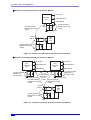
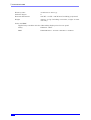
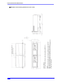
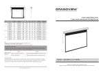
■ External dimensions (WF1973) ......................................................................... 147
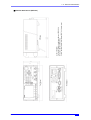
■ External dimensions (WF1974) ......................................................................... 148
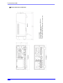
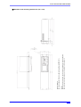
RACK MOUNTING DIMENSIONS ..................................................................149
■ Inch rack mounting dimensions (for 1 unit) ........................................................ 149
■ Inch rack mounting dimensions (for 2 units) ...................................................... 150
■ Millimeter rack mounting dimensions (for 1 unit) ............................................... 151
■ Millimeter rack mounting dimensions (for 2 units).............................................. 152
Index ................................................................................................................153
WARRANTY ....................................................................................................157
Figures and Tables
Figure 3-1. Front Panel of WF1973............................................................................ 8
Figure 3-2. Rear Panel of WF1973 ............................................................................ 9
Figure 3-3. Front Panel of WF1974.......................................................................... 10
Figure 3-4. Rear Panel of WF1974 .......................................................................... 11
Figure 3-5. Multi-I/O Connector Pin Assignment...................................................... 17
Figure 3-6. Cautions on Floating Ground Connection for WF1973 .......................... 20
Figure 3-7. Cautions on Floating Ground Connection for WF1974 .......................... 20
Table 3-1. Signals Selectable for Sync/Sub-Output ................................................. 13
Table 3-2. Multi-I/O Connector Function Allocation.................................................. 18
VIII
MULTIFUNCTION GENERATOR
1.
1.1
OVERVIEW
Features
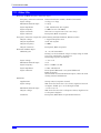
The WF1973 and WF1974 are multifunctional generators based on direct digital synthesizers
(DDS).
The WF1973 is a 1-channel generator, while the WF1974 is a two-channel generator.
• Highest frequency: 30 MHz (sine wave), 15 MHz (square wave, pulse)
• Frequency accuracy: ±(3 ppm + 2 pHz), high resolution of 0.01 µHz. 10 MHz external
frequency reference can be used.
• Maximum output voltage: 20 Vp-p/open, 10 Vp-p/50 Ω
• Large number of standard parameter-variable waveforms: Sine wave, square wave
(variable duty), pulse (variable pulse width/duty, leading edge time, trailing edge time),
ramp wave (variable symmetry), CF controlled sine wave (variable crest factor), staircase
sine wave (variable number of steps), Gaussian pulse (variable σ), Sin(x)/x (variable
number of zero crossings), exponential rise/fall (variable time constant), damped
oscillation (variable oscillation frequency, damping time constant), pulse surge (variable
rising and duration times), trapezoid (variable rise, fall, and upper base width), and so on.
• Large-capacity arbitrary waveform memory: 512 K words max., saving capacity: 128
waveforms/4 M words
• Phase and waveform remain continuous even when frequency is changed or during
frequency sweep.
• Square wave, pulse with variable duty and high resolution of 0.0001%
• Pulse with variable leading edge time and trailing edge time
• Various oscillation modes
• Continuous oscillation
• Modulation: FM, FSK, PM, PSK, AM, DC offset modulation, PWM
• Sweep: Frequency, phase, amplitude, DC offset, duty
• Burst oscillation: Auto burst, trigger burst, gate oscillation, triggered gate oscillation
• Sequence oscillation: Variable waveform/ frequency/ phase/ amplitude/ DC offset/
square wave duty, constant value/ linear interpolation, jump/ repeat/ hold/ branch
• Sequence function for easy test waveform creation and adjustment
Flexible waveform creation possible through combination with standard parametervariable waveforms
Frequency, phase, amplitude, etc., can be rapidly changed and swept
• Intuitive user interface through use of high-resolution QVGA TFT color LCD
• Two-channel ganged function with 2 phases, constant frequency difference, constant
frequency ratio, and differential output (only WF1974)
• Floated from housing for each channel to reduce effect of ground loop
• Multiple-phase oscillator can be configured by synchronizing multiple units
• USB and GPIB interfaces provided
• Thin and lightweight: Height of approx. 9 cm, weight of approx. 2.1 kg
WF1973/WF1974
1
1. OVERVIEW
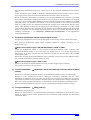
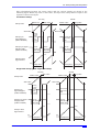
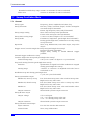
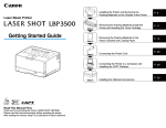
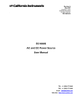
1.2
Operating Principles
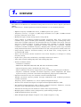
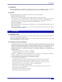
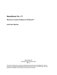
■ WF1973 block diagram
ANALOG
A/D
WAVE
MEMORY
EXTERNAL
MODULATION
LPF
EXTERNAL
ADDITION
16bit
512Kw
PGA
r1V
MOD/ADD
IN
2
r2Vmax
FCTN
OUT
LPF
ISOLATION
DDS
0/-10/-20/-30dB
16bit2CH
D/A
5
r10Vmax
TTL/r3V
LPF
SYNC/SUB
OUT
120MHz
CLOCK
GENERATOR
D/A
DC OFFSET
20MHz
100V...230V
㨪LINE
AC/DC
10MHz REF IN
+12V
REF OUT
SYSTEM
CONTROLLER
TRIG IN
FRONT
PANEL
UNIT
USB
GPIB
for ANALOG
for SYSTEM
CONTROLLER
POWER
SUPPLY
FAN
MULTI
I/O
■ Analog block
• The DDS (digital direct synthesizer) uses a 120 MHz clock to generate various types of
oscillation and waveforms. Modulation, sweep, burst, and sequence are also processed
within the DDS.
• The digital waveforms generated by the DDS are controlled to the specified polarity
(normal, inversed) in the amplitude range (−FS/0, ±FS, 0/+FS), and following digital
amplitude adjustment, the signal is input into the digital to analog (D/A) converter.
• The waveform converted into an analog signal by the D/A is then smoothed by the lowpass
filter (LFP), and the amplitude is controlled in 10 dB steps by the programmable gain
amplifier (PGA).
• The external addition signal and DC offset are added to the PGA output. When an output
voltage exceeding ±2V/open is required, output is done via the ×5 amplifier.
• The maximum output voltage of the product is either 20 Vp-p or 4 Vp-p depending on
whether or not the ×5 amplifier is used. Also depending on this, the external addition gain
is either ×10 or ×2.
• After passing through the LPF, the external modulation signal undergoes A/D conversion
and is then input to the DDS.
2
MULTIFUNCTION GENERATOR
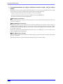
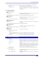
1.2 Operating Principles
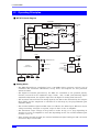
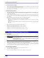
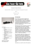
■ WF1974 block diagram
ANALOG CH2
ANALOG CH1
EXTERNAL
MODULATION
LPF
A/D
WAVE
MEMORY
EXTERNAL
ADDITION
16bit
512Kw
PGA
r1V
MOD/ADD
IN
2
r2Vmax
FCTN
OUT
LPF
ISOLATION
0/-10/-20/-30dB
16bit2CH
D/A
DDS
5
r10Vmax
TTL/r3V
LPF
SYNC/SUB
OUT
120MHz
CLOCK
GENERATOR
D/A
DC OFFSET
20MHz
100V...230V
㨪LINE
AC/DC
10MHz REF IN
+12V
REF OUT
for ANALOG CH1
SYSTEM
CONTROLLER
FRONT
PANEL
UNIT
USB
GPIB
TRIG IN CH1
for ANALOG CH2
TRIG IN CH2
for SYSTEM
CONTROLLER
POWER
SUPPLY
FAN
MULTI
I/O
• The analog block is insulated from the system controller block located in the housing
potential.
• In the WF1974, the analog block comprises two channels, each individually isolated from
the housing potential.
■ System controller block
• This block performs control of the analog block, including the display, panel key
processing, remote control (GPIB, USB) processing, trigger input processing, frequency
reference control, DDS control, amplitude, and DC offset.
• A 20 MHz crystal oscillator is used as the basic oscillation of the DDS.
• The signal to synchronize multiple units is sent to REF OUT (frequency reference output),
and the inter-channel sync (WF1974 only) is sent to the analog block of each channel.
■ Power supply block
• The AC/DC directly connected to the power supply input is in a constantly powered state.
• Control of each power supply circuit is done through power switch manipulation.
WF1973/WF1974
3
2.
2.1
PREPARATIONS BEFORE USE
Checking Before Use
a) Safety check
To ensure safety in using the WF1973/WF1974, the user should read the following sections
of this instruction manual before using the WF1973/WF1974:
• Safety Precautions (provided at the beginning of this instruction manual)
• 2.3 Grounding and Power Supply Connection
b) Appearance and accessories check
If an abnormality (such as a flaw or dent) is found on the outside surface of the corrugated
box, carefully check if the product is adversely affected when removing the product from the
corrugated box.
After opening the corrugated box, check the items contained in the box.
If an abnormality such as a flaw or dent is found on the product, or an accessory is missing,
contact NF Corporation or its representative.
• Appearance check
Check that no abnormalities such as a flaw and dent are found on the panel, controls,
connectors, and so forth.
• Configuration and accessory check
The accessories of this product are listed below. Check that there are no missing items
and no flaws are found.
Main unit................................................................................................................. 1
Instruction Manual (Basics)................................................................................... 1
CD (PDF instruction manuals, application software) .......................................... 1
PDF instruction manuals:
Basics, Application, Remote Control,
Arbitrary Waveform Editing Software, Sequence Editing Software,
LabVIEW Driver
Application software:
Arbitrary Waveform Editing Software, Sequence Editing Software,
LabVIEW Driver
Power cord set (2 m, with 3-prong plug)................................................................ 1
WARNING This product contains high-voltage parts. Never remove the cover.
All internal inspections of this product are to be performed only by service
technicians qualified by NF Corporation.
4
MULTIFUNCTION GENERATOR
2.2 Installation
c) Repacking
When repacking this equipment for transportation, etc., use a shipping carton of sufficient
strength and capacity to safely accommodate the equipment and hold its weight.
d) Options
The following options are available and can be purchased separately.
• Multi-I/O cable (PA-001-1318)
This cable is used when using the multi-I/O connector on the rear panel.
A 2 meter multi-core shielded cable is connected to the mini-Dsub 15-pin connector. Since
the opposite side is cut off, process that side according to the connection destination.
For the connector's pin assignment and cable differentiation, ) p. 18.
• Rack mount adapters
These adapters are for mounting the equipment on a 19-inch IEC, EIA standard rack, or
JIS standard rack.
Each type of adapter is available as a 1-unit and 2-unit model (for side-by-side mounting),
for a total lineup of 4 models.
2.2
Installation
a) Installation sites
Do not place the equipment with the rear panel facing down, because this may damage the
connectors and hinder ventilation.
Place the equipment on a flat surface such as a desk so that the four rubber feet and stands
on the bottom side rest on that surface.
b) Installation location conditions
• This product uses a fan for forced-air cooling and features air intake and exhaust vents on the
side and rear panels for this purpose. To allow for ample air flow, be sure to maintain a gap of
at least 10 cm between the sides and rear of this product and walls or other obstructions.
• Install this product in a location that meets the following conditions for temperature and
humidity ranges.
Operating conditions: 0 to 40ºC, 5 to 85%RH
Storage conditions: −10 to 50ºC, 5 to 95%RH
Further, a condensation-free environment must be ensured. For limitations related to
absolute humidity, refer to the specifications in this manual.
• Do not install the WF1973/WF1974 in the following locations:
• Location with flammable gas
An explosion may occur. Never install and use this product in such a location.
• Outdoors, or location exposed to direct sunlight or near a fire or heat source
The full performance of this product may not be obtained, or failure may occur.
• Location with corrosive gas, moisture, dust, or high humidity
This product may become corroded or fail.
• Location near an electromagnetic field source, high-voltage device, or power line
This product may malfunction.
• Location exposed to excessive vibration
This product may malfunction or fail.
WF1973/WF1974
5
2. PREPARATIONS BEFORE USE
c) Panel and case cleaning
Use a soft cloth to wipe dust from the panel and case. If soiling is severe, moisten the cloth
with a neutral detergent and wring it out well.
Do not use volatile substances such as thinners and benzene, or commercial wipes, as these
may deform or peel the finish.
d) Rack mounting method
When provided with a rack mount adapter (option), this equipment can be mounted on a 19inch IEC, EIA standard rack, or JIS standard rack. Either one unit, or two side-by-side
units, can be mounted.
First, attach the rack mount adapter to the main unit, and then mount the main unit into
the rack. For the rack mount adapter handling method, refer to the manual included with
the adapter.
When rack mounting the main unit, observe the following cautions.
• Be sure to install rails in the rack to support the equipment.
• Mounting the equipment into a fully enclosed rack may cause it to fail due to rising
temperature.
Be sure to provide sufficient ventilation openings and forcibly cool the inside of the rack
with fans.
For external dimensions for rack mounting, refer to:
Inch rack mounting dimensions (for 1 unit) ) p. 149
Inch rack mounting dimensions (for 2 units) ) p. 150
Millimeter rack mounting dimensions (for 1 unit) ) p. 151
Millimeter rack mounting dimensions (for 2 units) ) p. 152
2.3
Grounding and Power Supply Connection
a) Grounding
Be sure to ground the equipment.
WARNING This product uses a line filter. Be sure to ground this product. Otherwise, an
electric shock may occur.
To prevent electric shock, be sure to safely implement grounding such that
ground resistance is 100 Ω or lower.
When a 3-prong power plug that includes a protective ground contact is connected to a 3prong power supply outlet, this product is grounded automatically.
This product does not come with a 3-prong to 2-prong conversion adapter. When using a
separately sold 3-prong to 2-prong conversion adapter, be sure to connect the grounding
wire of the adapter to the grounding terminal next to the outlet.
b) Power supply conditions
Voltage range: 100 V AC to 230 V AC ±10% (250 V or lower)
Frequency range: 50 Hz/60 Hz
Power consumption: WF1973: 50 VA or lower; WF1974: 75 VA or lower
6
MULTIFUNCTION GENERATOR
2.4 Calibration
c) Power supply connection procedure
1) Check that the commercial power supply voltage to be connected is within the voltage
range specified for the equipment.
2) Connect the power cord to the power supply inlet on the rear panel of the equipment.
3) Connect the power cord plug to the 3-prong power supply outlet.
The withstand voltage of the main unit proper is 1500 Vrms (AC).
CAUTION
2.4
The power cord supplied with this equipment is designed to be used for this
equipment only. Do not use this power cord for other equipment or purposes.
Calibration
This equipment should undergo performance testing about once a year as a guideline,
although this depends on the usage environment and usage frequency. Moreover, when using
this equipment to perform important measurements and tests, the execution of a performance
test immediately before is recommended.
Performance testing of this equipment should be performed by a person with general
knowledge of test instruments and experienced in their operation.
For details on performance tests, ) “10. MAINTENANCE” in the Application Instruction
Manual.
WF1973/WF1974
7
3.
3.1
PANELS AND I/O TERMINALS
Panel Components and Operations
This section describes the names and functions of the various components on the front and
rear panels.
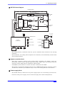
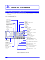
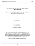
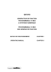
3.1.1 Front panel of WF1973
Figure 3-1. Front Panel of WF1973
Numeric keypad
Used for numerical input
) p. 31
Basic parameter
shortcut keys
Press to allow the waveform,
frequency, amplitude, and DC
offset to be changed
) p. 34
MENU key
Displays the top menu
) p. 29
LCD panel
UNDO key
Press to undo setting changes.
) p. 35
CANCEL key
Press to cancel.
) p. 35
ENTER key
Press to enter a setting.
) p. 35
Arrow keys
Press to select items, or increase/
decrease values.
) p. 30
Modify knob
Press to select items, or increase/
decrease values.
) p. 30
Manual trigger key
Used for sweep, burst trigger
) pp. 90, 111, 115, 120
Triggered lamp
Lights when a trigger is accepted
) pp. 90, 111, 115, 120
Power switch
) p. 21
Soft keys
The manipulation
parameter is displayed on
the LCD panel.
) p. 26
NEXT key
Press to switch setting
screen pages.
) p. 26
External trigger input terminal ) p. 14
External modulation/addition input terminal
) p. 14
Sync/sub-output terminal ) p. 13
Waveform output on/off key
Press to switch waveform output on/off.
When on, the lamp on the left is lit. ) p. 41
Waveform output terminal ) p. 12
Figure 3-1. Front Panel of WF1973
8
MULTIFUNCTION GENERATOR
3.1 Panel Components and Operations
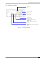
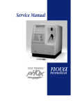
3.1.2 Rear panel of WF1973
Figure 3-2. Rear Panel of WF1973
Exhaust vent
) p. 5
Power supply input
) p. 6
USB connector
GPIB connector
Multi-I/O connector
Used for sweep, sequence control,
sync code output
) p. 16
Frequency reference output terminal
) p. 16
External 10 MHz frequency reference input
terminal
) p. 15
Figure 3-2. Rear Panel of WF1973
WF1973/WF1974
9
3. PANELS AND I/O TERMINALS
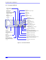
3.1.3 Front panel of WF1974
Figure 3-3. Front Panel of WF1974
Numeric keypad
Used for numerical input
) p. 31
Basic parameter
shortcut keys
Press to allow the waveform,
frequency, amplitude, and DC
offset to be changed
) p. 34
MENU key
Displays the top menu
) p. 29
LCD panel
UNDO key
Press to undo setting changes
) p. 35
CANCEL key
Press to cancel.
) p. 35
ENTER key
Press to enter a setting
) p. 35
Arrow keys
Press to select items, or
increase/decrease values
) p. 30
Modify knob
Press to select items, or
increase/decrease values
) p. 30
Manual trigger key
Used for sweep, burst trigger
) pp. 90, 111, 115, 120
Triggered lamp
Lights when a trigger is accepted
) pp. 90, 111, 115, 120
Power switch
) p. 21
Soft keys
The manipulation
parameter is displayed on
the LCD panel.
) p. 26
NEXT key
Press to switch setting
screen pages.
) p. 26
CH1/CH2 switching key
Press to switch the channel
to be set on the LCD panel.
) p. 38
CH2 sync/sub-output terminal
) p. 13
CH2 waveform output on/off key
Press to switch CH2 waveform output on/off.
When off, the lamp on the left is lit.
) p. 41
CH2 waveform output terminal
) p. 12
CH1 sync/sub-output terminal
) p. 13
CH1 waveform output on/off key
Press to switch CH1 waveform output on/off.
When on, the lamp on the left is lit.
) p. 41
CH1 waveform output terminal
) p. 12
Figure 3-3. Front Panel of WF1974
10
MULTIFUNCTION GENERATOR
3.1 Panel Components and Operations
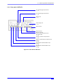
3.1.4 Rear panel of WF1974
Figure 3-4. Rear Panel of WF1974
CH1 external trigger input terminal
) p. 14
CH2 external trigger input terminal
) p. 14
Exhaust vent
) p. 5
Power supply input
) p. 6
USB connector
GPIB connector
Multi-I/O connector
Used for sweep, sequence control,
sync code output
) p. 16
Frequency reference output terminal
) p. 16
External 10 MHz frequency reference input
terminal
) p. 15
CH2 external modulation/addition input
terminal
) p. 14
CH1 external modulation/addition input
terminal
) p. 14
Figure 3-4. Rear Panel of WF1974
WF1973/WF1974
11
3. PANELS AND I/O TERMINALS
3.2
I/O Terminals
WARNING To prevent electric shocks, do not apply a voltage exceeding 42 Vpk (DC+AC
peak) between the ground of the BNC connectors insulated from the housing
and the housing.
Also, do not apply a voltage exceeding 42 Vpk (DC+AC peak) between the
grounds of the BNC connector groups insulated from the housing. “BNC
connector group”, as used here, refers to multiple BNC connectors that are
connected to a common ground.
If such a voltage were to be applied, the internal voltage limiting elements will
try to curb the working voltage, but if the voltage is too large, equipment burnout
may result.
) p. 19
CAUTION
Do not apply a voltage from external to the output terminal, as this may damage
the equipment.
CAUTION
Do not apply a voltage exceeding the maximum input level to the input terminal,
as this may damage the equipment.
CAUTION
If there is a difference in potential between the ground of a BNC connector
insulated from the housing and the housing, do not short circuit the hot side of
that BNC connector and the housing, as this may damage the equipment.
CAUTION
If a difference in potential exists between the grounds of the BNC connectors,
do not short circuit these BNC connector grounds, as this may damage the
equipment.
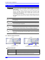
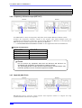
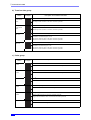
3.2.1 Waveform output (FCTN OUT)
WF1973
WF1974
FCTN OUT
[Insulated from housing]
CH1
FCTN OUT
[Insulated from housing]
CH2
FCTN OUT
[Insulated from housing]
This is the main output.
■ Output characteristics
12
Output voltage
Maximum ±10 V/open
Output impedance
50 Ω
Load impedance
0 Ω or higher (short-circuit protection provided)
Signal GND
Insulation from the housing (42 Vpk max.)
WF1974: Insulation also between channels (42 Vpk max.)
MULTIFUNCTION GENERATOR
3.2 I/O Terminals
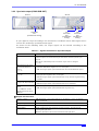
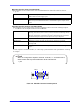
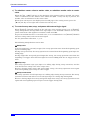
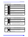
3.2.2 Sync/sub-output (SYNC/SUB OUT)
WF1973
WF1974
SYNC/SUB
OUT
[Insulated from housing]
CH1
SYNC/SUB
OUT
[Insulated from
housing]
CH2
SYNC/SUB
OUT
[Insulated from
housing]
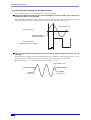
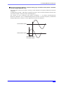
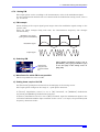
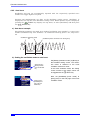
A sync signal is output according to the waveform or oscillation status. This signal can be
used as the oscilloscope synchronization signal.
As shown in the following table, the output signal can be selected according to the
oscillation mode.
Table 3-1. Signals Selectable for Sync/Sub-Output
Oscillation Mode
Selectable Output Signal
All
50% duty TTL level logic signal that rises at zero phase position of
reference phase of waveform output (hereafter, reference phase sync
signal).
The phase relationship with waveform output can be changed.
) p. 45
Modulation mode with
internal modulation
source
) p. 74
・Reference phase sync signal
・Internal modulation signal (−3 V to +3 V/open)
・TTL level logic signal synchronized with internal modulation signal
Sweep oscillation mode
) p. 92
・Reference phase sync signal
・Sweep X drive signal (0 V to +3 V/open)
・TTL level logic signal synchronized with sweep, marker signal mixing
possible
Burst oscillation mode
) pp. 108, 111, 115, 120
・Reference phase sync signal
・TTL level logic signal synchronized with burst oscillation
Sequence oscillation
mode
) “6.2 Basics” in the
Application Instruction
Manual
・Reference phase sync signal
・TTL level logic signal synchronized with sequence step
■ Output characteristics
Output voltage
TTL level (low: 0.4 or lower; high: 2.7 V or higher), −3 V to +3 V/open,
0 V to +3 V/open
Output impedance
50 Ω
Load impedance
50 Ω or higher recommended
Signal GND
Same potential as same channel waveform output, insulated from
housing (42 Vpk max.).
WF1974: Insulation also between channels (42 Vpk max.)
WF1973/WF1974
13
3. PANELS AND I/O TERMINALS
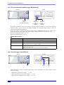
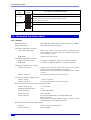
3.2.3 External modulation/addition input (MOD/ADD IN)
WF1973
WF1974
MOD/ADD
IN
[Insulated from housing]
CH1
MOD/ADD
IN
[Insulated from
housing]
CH2
MOD/ADD
IN
[Insulated from
housing]
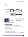
When the modulation source is external, except for FSK and PSK, an external modulation
signal is input. In the case of the FSK and PSK, the external trigger input is used as
external modulation signal input.
When not used as external modulation signal input, MOD/ADD IN may be used as the
external addition signal input. The gain during external addition is either ×2 or ×10.
External modulation input: ) p. 73.
External addition input: ) p. 57.
■ Input Specifications
Input voltage
±1 V full scale
Maximum allowed input
±2 V
Input impedance
10 kΩ
Input frequency
During modulation: DC to 25 kHz
During addition: DC to 10 MHz (−3 dB)
Signal GND
Same potential as same channel waveform output, insulated from
housing (42 Vpk max.).
WF1974: Insulation also between channels (42 Vpk max.)
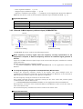
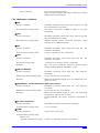
3.2.4 External trigger input (TRIG IN)
WF1973
WF1974
TRIG
IN
CH2
TRIG
IN
CH1
TRIG
IN
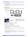
TRIG IN may be used as external trigger input in the following cases. The polarity setting
can be changed.
• Single-shot sweep start trigger ) p. 90.
• Gated single-shot sweep start trigger ) p. 90.
• Trigger burst oscillation start trigger ) p. 111.
14
MULTIFUNCTION GENERATOR
3.2 I/O Terminals
• Gate of gated oscillation ) p. 115.
• Triggered gate oscillation trigger ) p. 120.
• Sequence oscillation start trigger ) “6.2 Basics” in the Application Instruction Manual
TRIG IN can also be used as the external modulation input for FSK and PSK ) p. 73
■ Input Characteristics
Input voltage
TTL level (low: 0.8 V or lower; high: 2.6 V or higher)
Maximum allowed input
−0.5 V to +5.5 V
Input impedance
10 kΩ, pull up to +3.3 V
Signal GND
Same potential as housing
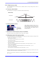
3.2.5 External 10 MHz frequency reference input (10 MHz REF IN)
WF1973
WF1974
10MHz REF IN
[Insulated from housing]
10MHz REF IN
[Insulated from housing]
10 MHz REF IN can be used for the following purposes.
■ When frequency accuracy higher than the frequency accuracy specification of the
equipment is required, or when the frequency reference of a different signal generator is
desired
Input the 10 MHz reference signal output from an external frequency standard or another
signal generator.
Enable external frequency reference setting.
) “5. USING EXTERNAL FREQUENCY REFERENCE” in the Application Instruction
Manual
■ To unify the frequency and phase for multiple WF1973, WF1974 units
Connect the frequency reference output of the master unit when multiple units are
combined in synchronous connection, or the master WF1973 or WF1974, to the external 10
MHz frequency reference input of the WF1973 or WF1974.
Set the frequency setting of each unit to the same value.
Also enable external frequency reference setting for the slave units and perform phase
synchronization with the master unit.
) “4. SYNCHRONIZING MULTIPLE UNITS” in the Application Instruction Manual
The frequency accuracies of the connected WF1973 and WF1974 units are all the same as
that of the master unit.
An external frequency standard can also be used for the master unit.
■ Input Characteristics
Input voltage
0.5 Vp-p to 5 Vp-p
Maximum allowed input
10 Vp-p
Input impedance
1 kΩ, AC coupled
WF1973/WF1974
15
3. PANELS AND I/O TERMINALS
Input frequency
10 MHz (±0.5% (±50 kHz))
Input waveform
Sine or square (50 ±5% duty)
Signal GND
Insulated from housing and each channel waveform output (42 Vpk max.)
3.2.6 Frequency reference output (REF OUT)
WF1973
WF1974
REF OUT
REF OUT
Use REF OUT to unify the frequency and phase for multiple WF1973, WF1974 units.
Connect the frequency reference output of the master unit when multiple units are
combined in synchronous connection, or the master WF1973 or WF1974, to the external 10
MHz frequency reference input of the WF1973 or WF1974.
) “4. SYNCHRONIZING MULTIPLE UNITS” in the Application Instruction Manual
■ Output Characteristics
Output voltage
1 Vp-p / 50 Ω
Output impedance
50 Ω, AC coupled
Output frequency
10 MHz
Output waveform
Square
Signal GND
Same potential as housing
Check
Do not connect any equipment other than the WF1973 and WF1974 not
specified by NF Corporation to the frequency reference output.
The special signal that is output from this terminal during synchronization may
make the operation of such connected equipment unstable.
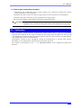
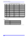
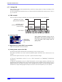
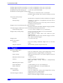
3.2.7 Multi-I/O (MULTI I/O)
WF1973
MULTI I/O
WF1974
MULTI I/O
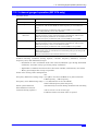
MULTI I/O can be used for sweep control and sequence control. It outputs the step
synchronization code for the sequence.
16
MULTIFUNCTION GENERATOR
3.2 I/O Terminals
■ Control input for sweep oscillation mode
The following types of control for sweep oscillation can be done with 3-bit logic input.
) p. 94
Start
Start the sweep from the start through fall input.
ORed with external trigger input.
Stop
Stop the sweep through fall input.
Hold/resume
Hold the sweep through fall input during sweep execution.
The sweep is resumed from where it was held through rise input during
hold.
■ Control input for sequence oscillation mode
The following types of control for sequence oscillation can be done with 4-bit logic input.
) “6.2 Basics” in the Application Instruction Manual
Start or state branch
Start control and state branch control can be selected.
During start control, the sequence is started from the beginning through
fall input. ORed with external trigger input.
During state branch control, the sequence is branched to the specified
destination step through low level input upon step completion.
Stop
Stop the sequence through fall input.
Hold/resume
Hold the sequence through fall input during sequence execution.
The sequence is resumed from where it was held through rise input
during hold.
Event branch
The sequence is branched to the specified destination step through fall
input.
In the sequence oscillation mode, the 4-bit step synchronization code specified for each step
is output.
Check
When not using control input for multi-I/O connector, it is recommended to
disable control input to prevent malfunction due to external noise.
) p. 94
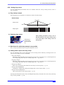
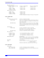
Figure 3-5. Multi-I/O Connector Pin Assignment
10
5
1
15
11
6
Figure 3-5. Multi-I/O Connector Pin Assignment
WF1973/WF1974
17
3. PANELS AND I/O TERMINALS
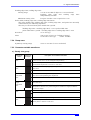
Table 3-2. Multi-I/O Connector Function Allocation
Sequence Oscillation
Mode
Option Cable Color and
Marking
Not used
Step sync code D0 (LSB)
Light brown Black ■
Output
Not used
Step sync code D1
Light brown Red ■
3
Output
Not used
Step sync code D2
Yellow Black ■
4
Output
Not used
Step sync code D3 (MSB)
5
Output
Not used
Not used
6
GND
–
–
Bright green Red ■
7
GND
–
–
Gray Black ■
8
GND
–
–
Gray Red ■
9
Reserved
10
GND
11
Input
Not used
Sequence event branch
Light brown Black ■■
12
Input
Sweep hold/resume
Sequence hold/resume
Light brown Red ■■
13
Input
Sweep stop
Sequence stop
14
Input
Sweep start
Sequence start or state
branch
15
Input
Not used
Not used
Shell
–
Pin No.
I/O
1
Output
2
Sweep Oscillation
Mode
Leave unconnected
Yellow Red ■
Bright green Black ■
Leave unconnected
–
White Black ■
–
–
White Red ■
Yellow Black ■■
Yellow Red ■■
Bright green Black ■■
–
Bright green Red ■■
Note: +5 V is output for testing purposes during production to pin No. 9. This pin is not designed for
use by users. Leave this pin unconnected, as its use may cause the operation of the equipment to
become unstable.
■ I/O characteristics
Input voltage
TTL level (low: 0.8 V or lower; high: 2.6 V or higher)
Maximum allowed input
−0.5 V to +5.5 V
Input impedance
10 kΩ, pull up to +5 V
Output voltage
TTL level (low: 0.4 V or lower; high: 2.7 V or higher)
Signal GND
Same potential as housing
Connector
Mini D-sub 15-pin
The connection cable is an option. Contact NF Corporation or an NF distributor for details.
18
MULTIFUNCTION GENERATOR
3.3 Cautions on Floating Ground Connection
3.3
Cautions on Floating Ground Connection
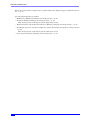
The signal ground of the BNC terminals for waveform output, sync/sub-output, and external
modulation/addition input, is shared, but since it is insulated from the housing (ground
potential), it can be connected to equipment that have a different potential. Moreover, the
potential has no influence even when the equipment is mounted in a rack.
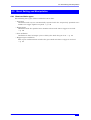
In the WF1974, the above-mentioned BNC terminals are also insulated between channels.
Further, the signal ground of the external 10 MHz frequency reference input is also
insulated from the housing. Therefore, noise caused by ground-loop is not a problem for
connection with a frequency standard. Nor is noise caused by ground-loop a problem in the
case of synchronized connection of multiple units of the WF1973 or WF1974.
However, in all cases, the floating voltage should be limited to 42 Vpk (DC+AC peak) or
lower to prevent electric shocks.
The other signal grounds are all connected to the housing. The housing itself is connected to
a protective grounding terminal.
WARNING To prevent electric shocks, do not apply a voltage exceeding 42 Vpk (DC+AC
peak) between the ground of the BNC connectors insulated from the housing
and the housing.
Also, do not apply a voltage exceeding 42 Vpk (DC+AC peak) between the
grounds of the BNC connector groups insulated from the housing. “BNC
connector group,” as used here, refers to multiple BNC connectors that are
connected to a common ground.
If such a voltage were to be applied, the internal voltage limiting elements will
try to curb the working voltage, but if the voltage is too large, equipment burnout
may result.
CAUTION
If there is a difference in potential between the ground of a BNC connector
insulated from the housing and the housing, do not short circuit the hot side of
that BNC connector and the housing, as this may damage the equipment.
CAUTION
If a difference in potential exists between the grounds of the BNC connectors,
do not short circuit these BNC connector grounds, as this may damage the
equipment.
WF1973/WF1974
19
3. PANELS AND I/O TERMINALS
■ Cautions on Floating Ground Connection for WF1973
Figure 3-6. Cautions on Floating Ground Connection for WF1973
FCTN OUT
ANALOG
CKT
SYNC/SUB OUT
MOD/ADD IN
Use with potential
difference of 42 Vpk
or less!
1 MΩ
Use with potential
difference of 42 Vpk
or less!
Housing ground
10 MHz
REF IN
EXT
REF
CKT
Use with potential
1 MΩ
difference of 42 Vpk
or less!
Housing ground
Figure 3-6. Cautions on Floating Ground Connection for WF1973
■ Cautions on Floating Ground Connection for WF1974
Figure 3-7. Cautions on Floating Ground Connection for WF1974
FCTN OUT
CH1
ANALOG
CKT
FCTN OUT
SYNC/SUB OUT
CH2
ANALOG
CKT
MOD/ADD IN
Use with potential
difference of
42 Vpk or less!
SYNC/SUB OUT
MOD/ADD IN
Use with potential
difference of
42 Vpk or less!
Use with potential
1 MΩ
difference of
Housing ground
Housing ground
42 Vpk
or less! Use with potential
Use with potential
difference of 42 Vpk
difference of 42 Vpk
or less!
or less!
1 MΩ
10 MHz
REF IN
EXT
REF
CKT
Use with potential
1 MΩ
difference of 42 Vpk
or less!
Housing ground
Figure 3-7. Cautions on Floating Ground Connection for WF1974
20
MULTIFUNCTION GENERATOR
4.
4.1
BASIC OPERATION
Power on/off Switching and Restoration of Settings
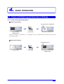
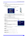
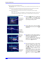
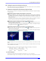
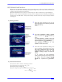
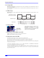
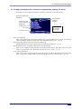
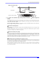
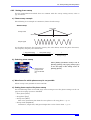
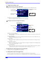
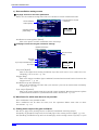
4.1.1 Power on/off switching method
■ Power-on procedure
The startup screen is displayed
Power off state
(standby state)
Press the
power switch.
The power is switched on.
Once the power is switched on, a self-check test is automatically executed and the unit
becomes operable.
■ Power-off procedure
The display goes off.
Power on state
WF1973/WF1974
Press the
power switch.
The power is switched off
(standby state)
21
4. BASIC OPERATION
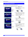
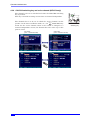
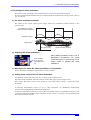
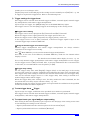
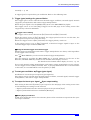
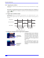
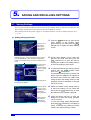
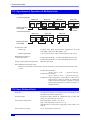
4.1.2 Restoration of settings at power-on
When the power is switched on/off with the power switch, the settings before the previous
time the power was switched off are restored when the power is switched on again.
The output on/off settings at power-on can be set on the Utility screen. ) p. 41
However, if the power supply to the equipment is directly cut off while the equipment's
power is on, the settings are set to the contents of setting memory 1 when the equipment is
powered on again.
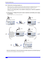
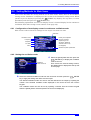
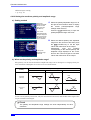
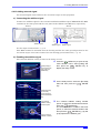
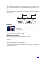
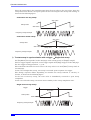
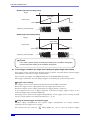
a) Restoration of settings when power switch is switched on/off while power supply
is connected
The most general case is illustrated below.
㨪LINE
㨪LINE
Power supply connected
Power supply connected
Settings
AAA
1
Press the power switch.
Power on state
The power is switched off
(standby state)
㨪LINE
㨪LINE
Even if the
power supply is
disconnected in
the power off
state, this has
no influence on
the next restore
operation.
1
Power supply disconnected
Power supply
reconnected
2
The power remains off
The power remains off
(standby state)
㨪LINE
Power supply connected
Settings
AAA
2
Press the power switch.
The power is switched on
(former settings are restored)
While the equipment power is off, even if the power supply is cut off due to the disconnection of
the cord or the shutoff of a connected breaker, this has no influence on the restore operation
the next time the equipment is powered on again.
22
MULTIFUNCTION GENERATOR
4.1 Power on/off Switching and Restoration of Settings
•The settings before the equipment was powered off last are restored.
•The output on/off settings at power-on can be set on the Utility screen. ) p. 41
Check
The previous settings can be restored only if the equipment was powered off
using the power switch.
WF1973/WF1974
23
4. BASIC OPERATION
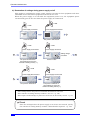
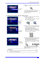
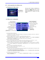
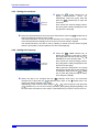
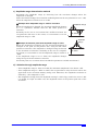
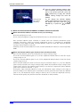
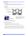
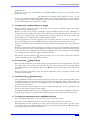
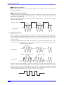
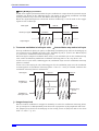
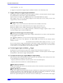
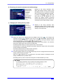
b) Restoration of settings during power supply on/off
This applies to switching the power supply on/off at one time for this equipment and other
embedded devices when this equipment is mounted in a rack.
When the power supply is cut off while the equipment power is on, the equipment power
automatically goes on the next time the power supply is reconnected.
㨪LINE
㨪LINE
Power supply connected
Power supply disconnected
Settings
AAA
1
Power on state
The power is switched off.
㨪LINE
㨪LINE
Power supply reconnected
1
Power supply connected
Settings
BBB
Settings
MMM
The power is switched on.
(The settings are set to the
contents of setting memory 1.)
Setting change
procedure
2
Power on state
㨪LINE
㨪LINE
Power supply disconnected
Power supply reconnected
Settings
MMM
2
The power is switched off.
The power is switched on.
(The settings are set to the
contents of setting memory 1.)
• The settings before the power is switched off cannot be restored.
• The contents of setting memory number 1 are set. ) p. 122
• The output on/off settings at power-on can be set on the Utility screen. ) p. 41
Check
Since the settings before the power supply is cut off are not restored, specify
the contents of setting memory number 1 beforehand if required. ) p. 122
24
MULTIFUNCTION GENERATOR
4.2 Screen Configuration and Operation
4.2
Screen Configuration and Operation
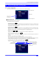
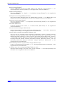
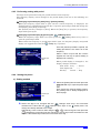
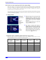
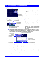
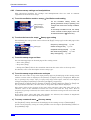
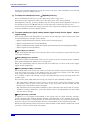
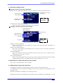
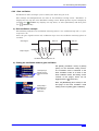
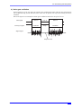
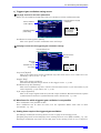
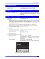
4.2.1 Screen configuration
The screen consists of three areas, as shown in the following figure.
Status display area
Setting area
Display format
switching tabs
Soft key display area
■ Status display area
Displays the status of the equipment.
The following items are displayed.
• Uncalibrated status UCal
Displayed when the calibration information of the equipment is lost due to a problem, and
the prescribed performance cannot be maintained. Since this is a malfunction, notify NF
Corporation or an NF distributor.
• Overheating status Temp
Displayed when the internal temperature of the equipment becomes abnormally high.
When this status is displayed during use at an ambient temperature of 40°C or lower, this
indicates a malfunction, so notify NF Corporation or an NF distributor.
• Remote status USB , GPIB
Displayed when the equipment is controlled via the USB or GPIB interface.
• External frequency reference status Ref
Displays whether a valid signal is input or not, when the external frequency reference is
enabled.
• Sequence status/channel mode (WF1974 only)
The status when the sequence oscillation mode is selected is displayed.
In the WF1974, the mode when the channel mode is other than independent (2-phase,
constant frequency difference, constant frequency ratio, and differential output).
• 2-channel same value (Both) setting (WF1974 only) Both
Displayed when the same setting is done for CH1 and CH2.
Remote status
Overheating status
Uncalibrated status
WF1973/WF1974
External frequency reference status
Sequence status/
2-channel
channel mode
same value (WF1974 only)
setting
(WF1974 only)
25
4. BASIC OPERATION
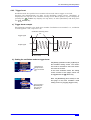
■ Setting area
This area is used to display and set the various parameters.
When multiple display formats can be selected, display format switch tabs are displayed on
the left side of the screen. ) p. 27
Due to the large number of setting parameters in the case of
modulation, sweep, and burst oscillation, the setting screen
consists of two or three pages. The screen pages can be switched
with the NEXT key.
ME
NEXT
Setting screen page position
display icon
Switching setting
screen pages with
the NEXT key
When there are several setting screen pages, an icon
indicating which page is displayed appears at the top center of the screen.
In the example on the left, there is a total of two setting
screen pages, and the icon indicates that the second page is
currently displayed.
Indicates that there are several
setting screen pages, which can
be switched with the NEXT key.
■ Soft key display area
Displays the functions of the soft keys allocated according to the status.
If five or more soft keys are allocated, “ ▼ n/m” is displayed over the right-most soft key. This
indicates that the set of soft keys belonging to the current setting screen extends of m
stages, and that the set corresponding to the nth stage is currently displayed. When the soft
key over which “ ▼ n/m” is displayed is pressed, the next set of soft keys is displayed.
Start
26
StartSt
ٕ
Indicates that the first of two
stages of soft keys is
displayed.
When this key is pressed, the
next stage of soft keys is
displayed.
MULTIFUNCTION GENERATOR
4.2 Screen Configuration and Operation
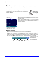
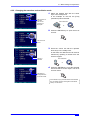
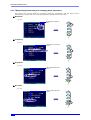
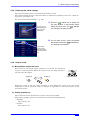
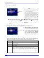
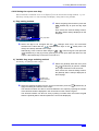
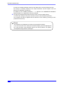
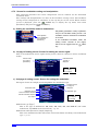
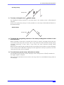
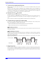
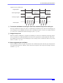
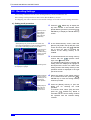
4.2.2 Switching display format with tabs (displaying waveform graph)
When a number of display formats can be selected, a display format switching tab is
displayed on the left side of the screen. When the Graph tab is displayed on the screen,
settings can be performed while checking the image of the output waveform.
a) Display format types
There are three types of display formats, as follows.
■ Graph display [Graph]
■ Text display [Text] (WF1973)
or [Single](WF1974)
Displays the settings of one channel in both
text and graph form, allowing the image of the
Displays the settings of 1 channel in
output waveform to be checked.
text form.
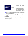
■ 2-channel simultaneous display [Dual] (WF1974 only)
Displays the settings of channel 1 and channel 2 in text form vertically superposed.
The channel to be set can be switched with the
CH1/CH2 key.
WF1973/WF1974
27
4. BASIC OPERATION
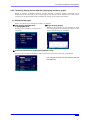
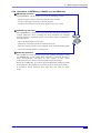
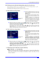
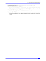
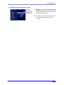
b) Switching the display format
1. In the example on the left, the Text tab
The Text tab
screen is
displayed.
screen is displayed.
On this screen, the settings are displayed
in text form.
2. Select the Graph tab with the arrow keys
or the modify knob.
Tab selection
The Graph tab is
selected.
or
3. The Graph tab screen display is switched
The Graph tab
screen is
displayed.
to by pressing the ENTER key. The
settings can be done while checking the
image of the output waveform on this
screen.
ENTER
Check
In the WF1974, display can be switched between 1-channel display and 2channel simultaneous display.
28
MULTIFUNCTION GENERATOR
4.2 Screen Configuration and Operation
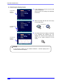
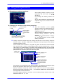
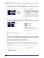
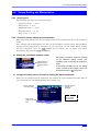
4.2.3 Top menu
Sequence oscillation, arbitrary waveform editing, system settings, saving and recalling
settings, and other actions are done by selecting the desired item from the top menu.
a) Displaying the top menu
Press the
MENU
menu key to display the following top menu window.
The top menu window opens.
FCTN
FREQ
AMPTD
OFFSET
MENU
Select the desired menu item using the
up/down arrow keys or the
modify knob,
and then press the ENTER ENTER key to display the menu item setting screen.
With the top menu window open, the desired menu item can also be specified by inputting a
number using the 0 ... 9
numeric keypad.
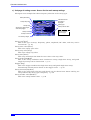
b) Actions possible using the top menu items
The menu items are displayed at the top left of each setting screen.
Settings and operations such as those described below can be done with the various menu
items.
Menu item
■ Oscillator
Almost all settings other than arbitrary waveform editing
and sequence oscillation can be set and manipulated.
When the power is applied, the Oscillator setting screen is
always displayed.
■ Sequence
Sequence oscillation setting and manipulation can be
done. ) “6. USING SEQUENCE OSCILLATON” in the
Application Instruction Manual
■ ARB edit
Arbitrary waveform editing can be done. ) “2. CREATING ARBITRARY WAVEFORMS” in
the Application Instruction Manual
■ Utility
Various settings and manipulations can be done. ) p. 39
■ Store memory
The settings can be saved to the setting memory. ) p. 122
■ Recall memory
The settings can be called from the setting memory. ) p. 124
WF1973/WF1974
29
4. BASIC OPERATION
4.3
Basic Settings and Operations
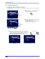
4.3.1 Changing the frequency, amplitude, and other values
a) Changing a value with the
up/down arrow keys or the
modify knob
1. Select the desired item with the arrow
keys or the modify knob.
In the example on the left, the [Freq]
frequency field is selected.
The frequency is
selected.
The current
frequency is
displayed.
Item selection
or
2. Press the ENTER key. The input field
The input field is
opened.
below the selected item opens and the
selected item status changes so that the
current value can be changed.
In this state, a value can also be input by
using the numeric keypad.
ENTER
3. Press the left/right arrow keys to move the
cursor to the digit of the value to be
changed.
In the example on the left, the cursor is
moved to the 1 kHz digit.
The digit to be
changed is the 1
kHz digit.
Cursor movement
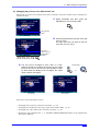
4. Increment or decrement the value of the
The value of the
changed digit is
now 2.
digit to be changed with the up/down
arrow keys or the modify knob.
In the example on the left, the value is
changed to 2 kHz.
The change is instantly reflected to the
output.
Value incrementing/
decrementing
or
30
MULTIFUNCTION GENERATOR
4.3 Basic Settings and Operations
5. Press the ENTER key to close the input
field.
ENTER
The input field
has closed.
If the CANCEL key is pressed instead of the ENTER
key, the value changed with the modify knob is
discarded and the status of step 1 (pre-change
setting) is returned to.
b) Changing a value with the 0 ... 9 numeric keypad
1. Select the desired item with the arrow
keys or the modify knob.
In the example on the left, the [Freq]
(frequency) field is selected.
The frequency is
selected.
The current
frequency is
displayed.
Item selection
or
2. Press a key of the numeric keypad. The
The input field
opens and a
value is input.
input field under the selected item opens
and the numeric value is input.
In the example on the left, “2” is input.
During numeric input, the left arrow key
serves as the delete key, and the right
arrow key as the zero input key.
Numeric input
7
8
9
4
5
6
1
2
3
0
.
3. Press the ENTER key or the unit key (soft
The setting is
changed and the
input field closes.
key) to set the input value and reflect it to
the output. The input field closes.
If the ENTER key is pressed, the setting is
performed in a unit without the “k” or “m”
prefix.
ENTER
or
If the CANCEL key is pressed instead of the ENTER
key, the input value is discarded and the setting
remains unchanged.
Check
During numeric input, the left arrow key serves as the delete key, and the right
arrow key as the zero input key.
WF1973/WF1974
31
4. BASIC OPERATION
Check
If a setting item is displayed on a soft key, the input field for that item can be
opened by pressing that soft key.
32
MULTIFUNCTION GENERATOR
4.3 Basic Settings and Operations
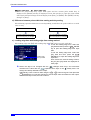
4.3.2 Changing the waveform and oscillation mode
1. Select the desired item with the arrow
The waveform is
selected.
The current
waveform is
displayed.
keys or the modify knob.
In the example on the left, the [Fctn]
(waveform) field is selected.
Item selection
or
2. Press the ENTER key to open the list of
choices.
ENTER
The choice list
opens.
3. Scroll the choice list with the up/down
arrow keys or the modify knob.
In this state, the desired item can also be
selected by inputting a number from the
numeric keypad.
“Ramp” is
selected.
Item selection
or
4. Press the ENTER key to set the selected
item and reflect it to the output. The list of
choices closes.
The setting is
changed and the
choice list closes.
ENTER
If the CANCEL key is pressed instead of the ENTER
key, the setting remains unchanged and the status
of step 1 is returned to.
WF1973/WF1974
33
4. BASIC OPERATION
4.3.3 Manipulating shortcut keys for changing basic parameters
The choice list or input field for waveform, frequency, amplitude, and DC offset can be
immediately opened with the corresponding basic parameter shortcut key.
■ Waveform
) p. 44
The waveform choice list
opens.
FCTN
FREQ
AMPTD
OFFSET
MENU
■ Frequency
) p. 44
The frequency input field
opens.
FCTN
FREQ
AMPTD
OFFSET
MENU
■ Amplitude
) p. 48
The amplitude input field
opens.
FCTN
FREQ
AMPTD
OFFSET
MENU
■ DC offset
) p. 50
The DC offset input field
opens.
FCTN
FREQ
AMPTD
OFFSET
MENU
34
MULTIFUNCTION GENERATOR
4.3 Basic Settings and Operations
4.3.4 Operations of ENTER key, CANCEL key, and UNDO key
■ ENTER key operation
The ENTER key can be used to perform the following actions.
・Open the input field or choice list for the selected item
・Set the value input from the numeric keypad
・Perform the function of the button displayed on the screen
■ CANCEL key operation
The CANCEL key can be used to perform the following cancellation
actions. However, once a setting has been changed, the original
setting cannot be returned to (this can be done with the UNDO key
described next).
CANCEL
ENTER
・Close an input field or choice list
・Discard a value input from the numeric keypad
UNDO
・Return a changed value to the original value with the modify knob
・Close the setting window or dialog box
■ UNDO key operation
The UNDO key can be used to restore the settings changed by using
the ENTER key or the modify knob. Changes to settings that have
been automatically executed as the result of the user's
manipulations can also be restored to the original settings.
When the UNDO key is pressed again immediately following undo
manipulation, the settings are restored to their state before undo.
It should be noted, however, that undo does not work for some
items.
WF1973/WF1974
35
4. BASIC OPERATION
4.3.5 Changing the display unit
a) Changing the prefix (unit prefix: k, m, M, etc.)
Frequency is used as an example below. The amplitude and pulse width can be changed in a
similar manner.
1. Select frequency and then press the
ENTER key to open the input field.
ENTER
The input field
opens.
2. Press the [Prefix] soft key and the cursor
will move to before “Hz”.
The right arrow key can also be used to
move the cursor to before “Hz”.
The cursor
moves to before
“Hz” when
[Prefix] is
pressed.
3. Change the unit to MHz, kHz, Hz, mHz, or uHz with the
Unit change
up/down arrow keys or the modify knob. Even when the
display unit and decimal point position are changed, the
value of the setting itself remains unchanged.
kHz display
36
or
MHz display
MULTIFUNCTION GENERATOR
4.3 Basic Settings and Operations
b) Changing Vp-p, Vrms, user-defined unit, etc.
Amplitude is used as an example below. The frequency and pulse width can be changed in a
similar manner.
1. Select amplitude and then press the
ENTER key to open the input field.
ENTER
The input field
opens.
2. Press the [Unit] soft key and the cursor will
move to “Vp-p”.
The right arrow key can also be used to
move the cursor to “Vp-p”.
The cursor
moves to “Vp-p”
when [Unit] is
pressed.
3. The unit can be changed to Vrms, dBV, or a userdefined unit with the up/down arrow keys or the modify
knob (in the case of sine wave, load impedance HighZ). Even when the display unit is changed, the output
value remains unchanged.
Vrms display
Unit change
or
dBV display
Also refer to the following sections:
• Changing the frequency and period settings ) p. 45.
• Changing the amplitude unit (Vp-p, Vpk, Vrms, dBm, dBV) ) p. 48.
• Changing the pulse width time and duty settings ) p. 61.
• Setting the user-defined unit ) “7. USING USER-DEFINED UNITS” in the Application
Instruction Manual
WF1973/WF1974
37
4. BASIC OPERATION
4.3.6 CH1/CH2 switching key and active channel (WF1974 only)
The channel to be set is switched each time the CH1/CH2 switching
key is pressed.
MENU
This key is invalid in setting screens that are channel independent.
FCTN OU
CH 1/CH 2
The channel that is to be set is called the “active channel” in this
MAN TRIG
product. In the burst oscillation mode, etc., the
MAN TRIG key
works for the active channel. Even if the screen is changed to a
channel independent screen, the channel that was active up to that
point is saved.
CH1 active
(CH1 = channel to be set)
NEXT
±10V
Zout 50Ω
CH1/CH2
switching key
CH2 active
(CH2 = channel to be set)
CH 1/CH 2
CH 1/CH 2
38
MULTIFUNCTION GENERATOR
4.3 Basic Settings and Operations
4.3.7 Actions possible in the Utility screen
a) Displaying the Utility screen
Select [Utility] in
the top menu and
press the ENTER
key
The top menu window is displayed by
pressing the MENU MENU key. In this
window, select [Utility] and then press the
ENTER
ENTER key to display the Utility
screen.
b) Utility screen configuration
Setting initialization
External addition setting
Power-on output setting
External 10 MHz frequency
reference enable/disable
External 10 MHz frequency
reference input status display
User-defined unit setting
Display setting
Phase synchronization
Operation sound setting
Modify direction setting
Internal information display
Channel mode setting
(WF1974 only)
2-channel same value setting On/Off
(WF1974 only)
Remote setting
Self check
Inter-channel
parameter copy
(WF1974 only)
Setting initialization [Reset]
Initializes the settings. The initial settings are continuous oscillation, sine wave, 1 kHz, 0.1
Vp-p/open, and output off. ) p. 41
External 10 MHz frequency reference enable/disable [Ext Reference]
Enables/disables the external 10 MHz frequency reference. ) “5. USING EXTERNAL
FREQUENCY REFERENCE” in the Application Instruction Manual
External addition setting [Ext Add]
Sets external addition gain. The setting can be selected from off, ×2, and ×10. ) p. 57
External 10 MHz frequency reference input status display [10MHz Ref In]
Displays whether a valid signal for external 10 MHz frequency reference input is available.
) “5. USING EXTERNAL FREQUENCY REFERENCE” in the Application Instruction
Manual
Power-on output setting [Power-On Output]
Sets the output on/off setting at power-on. ) p. 41
Phase synchronization[φ Sync]
Performs inter-unit synchronization during multiple unit synchronization connection and
inter-channel synchronization of the WF1974.
) “3.3 Phase Synchronization Between Channels” and “4. SYNCHRONIZING MULTIPLE
UNITS” in the Application Instruction Manual.
User-defined unit setting [User Unit]
Sets user-defined units. ) “7. USING USER-DEFINED UNITS” in the Application
Instruction Manual.
WF1973/WF1974
39
4. BASIC OPERATION
Remote setting [Remote]
Selects GPIB/USB and sets the GPIB address. The USB ID is also displayed. ) “8.1
Selecting Remote Interface [Remote]” in the Application Instruction Manual.
Display setting [Display]
Sets the backlight of the display. ) “8.2 Display Settings [Display]” in the Application
Instruction Manual.
Modify direction setting [Modify Direction]
Sets the movement direction when the modify knob is turned. ) “8.3 Modify Knob and
Modify Direction Setting [Modify Direction]” in the Application Instruction Manual.
Operation sound setting [Sound]
Sets the operation sound. ) “8.4 Operation Sound Setting [Sound]” in the Application
Instruction Manual.
Self-check [Self Check]
Performs internal status check. ) “8.5 Self Check [Self Check]” in the Application
Instruction Manual.
Internal information display [Information]
Displays the firmware version and latest calibration date. ) “8.6 Product Information
Display [Information]” in the Application Instruction Manual.
Channel mode setting [Channel Mode] (WF1974 only)
Sets the type of 2-channel ganged operation. Independent, 2-phase, constant frequency
difference, constant frequency ratio, and differential output can be selected from. ) “3.4
Maintaining Both Channels to Same Frequency (2-Channel Ganged Operation, 2-Phase)”,
“3.5 Keeping Frequency Difference Constant (2-Channel Ganged Operation, 2-Tone)”, “3.6
Keeping Frequency Ratio Constant (2-Channel Ganged Operation, Ratio)”, and “3.7
Obtaining Differential Output (2-Channel Ganged Operation, Differential)” in the
Application Instruction Manual.
Inter-channel parameter copy [Parameter Copy] (WF1974 only)
Copies the settings between channels. ) “3.1 Copying Settings Between Channels” in the
Application Instruction Manual.
2-channel same value setting On/Off [Both] (WF1974 only)
Switches on/off setting of the same value for both channels. ) “3.2 Unifying Settings of 2
Channels” in the Application Instruction Manual.
40
MULTIFUNCTION GENERATOR
4.3 Basic Settings and Operations
4.3.8 Restoring the initial settings
The initial settings can be restored from the Utility screen.
The initial settings that are restored consist of continuous oscillation, sine wave, 1 kHz, 0.1
Vp-p/open, and output off.
For a list of the initial settings, ) p. 126.
1. Press the
MENU MENU key to display the
top menu window. In that window, select
[Utility] and then press the ENTER ENTER
key to display the Utility screen.
In the top menu,
select [Utility] and
then press the
ENTER key.
2. On the Utility screen, select the [Reset]
field and then press the ENTER ENTER key.
The settings are initialized.
On the Utility
screen, select
[Reset] and then
press the ENTER
key.
4.3.9 Output on/off
a) Manipulation method on panel
Each time the waveform output on/off key is pressed, the waveform
output is switched on/off. When the output is on, the lamp located to
the left of the key lights.
OUT
FCTN OUT
SYNC/SUB OUT
CH 1
42Vpk
Output off
Output on
OUT
Output on/off key
OUT
OUT
When the output is off, the output terminal is open. When the output is on, the output
impedance is 50 Ω. Sync/sub output is always on regardless of the on/off setting of the
waveform output.
b) Setting at power-on
The waveform output on/off status at power-on can be specified.
The output setting at power-on can be selected from the following three.
• Off [Off]
The output is off.
• On [On]
The output is on.
WF1973/WF1974
41
4. BASIC OPERATION
• Return to previous setting [Last State]
The operation differs as follows according to the method used the previous time to set
the power off.
If the power was switched off the previous time with the power switch on the panel
The settings before the power was switched off are restored.
If the power was switched off the previous time by cutting off the power supply
The output is off.
This is the case when the equipment is mounted along with other devices on a
rack and the power supply to all the units is switched on/off at the same time.
The operation is done on the Utility screen.
In the top menu,
select [Utility] and
then press the
ENTER key.
1. Press the
MENU MENU key to display the
top menu window. In this window, select
[Utility] and then press the ENTER ENTER
key to display the Utility screen.
2. On the Utility screen, select the [PowerOn Output] field and then press the
ENTER key.
ENTER
On the Utility
screen, select
[Power-On
Output] and then
press the ENTER
key.
The power-on
output setting
window is
displayed.
3. The power-on output setting window is
displayed, so select the desired item and
then press the ENTER ENTER key.
The output setting condition choice list is
displayed, so select the desired item and
then press the ENTER ENTER key.
Set the output
setting condition.
4. Once the desired power-on output setting
Select [OK] and
then press the
ENTER key.
42
has been completed, select [OK] in the
lower part of the window and then press
the ENTER ENTER key. The power-on
output setting change is applied and the
window closes.
To not apply the power-on output setting
change, select [Cancel] in the lower part of
the window and then press the ENTER
ENTER key, or press the CANCEL CANCEL
key.
MULTIFUNCTION GENERATOR
4.4 Setting Methods for Main Items
4.4
Setting Methods for Main Items
This section describes the setting methods for the main items, mainly done on the Oscillator
setting screen. “Oscillator” is displayed at the top left of the Oscillator setting screen. When
another screen is displayed, pressing the MENU MENU key displays the top menu, so select
[Oscillator] and then press the ENTER ENTER key.
The following explanation uses the text display screen (1 channel display) in the continuous
oscillation mode. The setting screen consists of one page only.
4.4.1 Configuration of text display screen in continuous oscillation mode
This screen is where the basic settings for the output waveform are done.
Waveform
Oscillation mode
Polarity and amplitude
range of waveform
(depending on the
waveform, additional
selection buttons may
be displayed)
Frequency
Amplitude
DC offset
Phase
Waveform-specific parameters
4.4.2 Setting the oscillation mode
1. Select the [Mode] field and then press the
ENTER key to display the oscillation
mode choice list.
Even if there are several setting screens,
the [Mode] field is displayed at the top left
of each page.
ENTER
Oscillation
mode choice list
2. Select the desired oscillation mode from the choice list and then press the
ENTER ENTER
key to apply the setting and reflect it to the output.
The desired oscillation mode can also be set and reflected to the output by inputting the
number of the desired oscillation mode displayed in the choice list from the numeric
keypad.
The oscillation mode can also be set by inputting a number from the numeric keypad
while the [Mode] field is selected (without the choice list displayed).
WF1973/WF1974
43
4. BASIC OPERATION
4.4.3 Setting the waveform
1. Press the
FCTN
FCTN shortcut key to
display the waveform choice list.
Alternatively, select the [Fctn] field and
press the ENTER ENTER key to open the
choice list.
Even if there are several setting screens,
the [Fctn] field is always displayed at the
top right of the first page.
Waveform
choice list
2. Select the desired waveform from the choice list and then press the
ENTER ENTER key to
apply the setting and reflect it to the output.
The desired waveform can also be set and reflected to the output by inputting the number
of the desired waveform displayed in the choice list from the numeric keypad.
The desired waveform can also be set by inputting a number from the numeric keypad
while the [Fctn] field is selected (without the choice list displayed).
4.4.4 Setting the frequency
1. Press the
Frequency
input field
FREQ
FREQ shortcut key to
display the frequency input field, or select
the [Freq] field and then press the ENTER
ENTER key to open the input field.
Even if there are several setting screens,
the [Freq] field is always displayed at the
top left of the first page.
When [Period] is displayed in the [Freq]
field and the period and not the frequency
is displayed, either press the FREQ FREQ
key or press the [Freq] soft key, to switch
to the frequency display.
2. Select the digit to be changed with the
left/right arrow keys, and increment/
decrement the value with the
up/down arrow keys or the
modify knob. The
change is instantly reflected to the output.
Alternatively, enter a numeric value using the 0 ... 9 numeric keypad. Then press the
ENTER ENTER key or one of the unit keys (soft keys: [uHz] [mHz] [Hz] [kHz] [MHz]) to set
the input value and reflect it to the output. If the ENTER key is used, the unit is set to Hz.
44
MULTIFUNCTION GENERATOR
4.4 Setting Methods for Main Items
4.4.5 Performing setting with period
Settings can be performed using the period instead of the frequency.
The frequency display can be changed to the period display with one of the following two
methods.
○ Changing to period display with [Freq] / [Period] soft key
When the frequency input field is open and the current frequency is displayed, the
[Period] soft key is displayed. Press this key to open the period input field and change the
item display from [Freq] to [Period].
The [Period] soft key changes to [Freq]. When the [Freq] key is pressed, the frequency
input field opens again.
○ Changing to period display by pressing the FREQ FREQ key twice
While the frequency input field is not open, press the FREQ FREQ shortcut key twice to
open the period input field.
When either the frequency or period input field is open, the frequency display and period
display are toggled each time the FREQ FREQ key is pressed.
Once the period input field is opened, the
setting procedure is the same as for the
frequency.
When a value is input with the numeric
keypad, the unit key for period setting is
displayed as a soft key.
Period input
field
When period display is changed to, the
display changes as follows.
Item name: Freq
→ Period
Unit display: Hz
→ s
Soft key:
Period → Freq
4.4.6 Setting the phase
a) Setting method
1. Select the [Phase] field and then press the
Phase input
field
ENTER ENTER key to open the phase input
field.
Even if there are several setting screens,
the [Phase] field is always displayed on
the first page.
2. Select the digit to be changed with the
left/right arrow keys, and increment/
decrement the value with the
up/down arrow keys or the
modify knob. The
change is instantly reflected to the output.
Alternatively, enter a numeric value using the 0 ... 9 numeric keypad. Then press the
ENTER ENTER key or the [deg] unit key (soft key) to set the input value and reflect it to the
output. If the ENTER key is used, the unit is also set to deg.
WF1973/WF1974
45
4. BASIC OPERATION
b) Items that can be changed in the phase setting
The following items can be changed with the phase setting.
■ The phase difference between the sync/sub-output’s reference phase sync output and
waveform output can be changed
The following example assumes a phase setting of +90°. At this time, the waveform output’s
zero phase position is 90° ahead of the rise of the reference phase sync output.
Phase setting: +90°
Waveform output
Waveform output’s
zero phase position
Sync/sub-output
(reference phase sync output)
90°
■ The oscillation start/stop phase for burst oscillation, gated single-shot sweep can be
changed
The following example is burst oscillation with the oscillation start/stop phase set to +30°.
At this time, the oscillation starts at +30° and stops at the same +30° position.
Burst oscillation: ) p. 105, gated single-shot sweep: ) p. 89.
Phase setting: +30°
Oscillation
start at +30°
46
Oscillation
stop at +30°
MULTIFUNCTION GENERATOR
4.4 Setting Methods for Main Items
■ The phase difference between channels during sync oscillation and 2-phase oscillation
can be changed (WF1974 only)
The difference between the phase setting of each channel is the phase difference between
channels.
If [CH2 phase setting − CH1 phase setting] is positive, the waveform of CH2 is ahead of the
waveform of CH1, as shown in the following figure.
For details on sync oscillation and 2-phase oscillation, ) “3.3 Phase Synchronization
Between Channels” and “3.4 Maintaining Both Channels to Same Frequency (2-Channel
Ganged Operation, 2-Phase)” in the Application Instruction Manual.
CH1 waveform output
CH2 waveform output
CH2 phase setting –
CH1 phase setting
WF1973/WF1974
47
4. BASIC OPERATION
4.4.7 Setting the amplitude
a) Setting method
1. Press the
AMPTD
AMPTD shortcut key to
open
the
amplitude
input
field.
Alternatively, select the [Amptd] field and
then press the ENTER ENTER key to open
the amplitude input field.
Even if there are several setting screens,
the [Amptd] field is always displayed on
the first page. If [High] is displayed in the
[Amptd] field and the high level instead of
the amplitude is displayed, press the AMPTD
AMPTD key once more to switch to the
amplitude display.
Amplitude input
field
2. Select the digit to be changed with the
left/right arrow keys, and increment/
decrement the value with the
up/down arrow keys or the
modify knob. The
change is instantly reflected to the output.
Alternatively, enter a numeric value using the 0 ... 9 numeric keypad. Then press the
ENTER ENTER key or one of the unit keys (soft keys) to set the input value and reflect it to
the output.
b) Changing the unit (Vp-p, Vpk, Vrms, dBV, dBm, user-defined unit)
1. When the amplitude input field is open,
press the [Unit] soft key and move the
cursor to the unit position on the right end.
Place cursor on
unit
2. The unit can be changed with the
up/down arrow keys or the
modify
knob. (Units that cannot be used are not
displayed.) Even if the display unit is
changed, the actual output value remains
unchanged.
c) The units that can be used differ according to the waveform
Vp-p, Vpk, Vrms, dBV, dBm, and user-defined units can be used as the amplitude units.
However, the applicable waveforms are limited as follows (not applicable to DC).
Unit
Vp-p
Standard waveform and arbitrary waveform with amplitude range of ±FS
Vpk
Standard waveform and arbitrary waveform with amplitude range of 0/+FS, −FS/0
Vrms
Sine wave and noise
dBV
Sine wave and noise
1 Vrms = 0 dBV
dBm
Sine wave and noise
Voltage of 1 mW set as 0 dBm for the specified load impedance() p. 55)
Example: In the case of a load impedance setting of 50 Ω, 0 dBm = 223.6 mVrms/50 Ω.
Not usable when the load impedance setting is High-Z.
User-defined
unit
48
Applicable Waveform
All waveforms.
For details on user-defined waveforms, ) “7. USING USER-DEFINED
UNITS” in the Application Instruction Manual.
MULTIFUNCTION GENERATOR
4.4 Setting Methods for Main Items
d) AC+DC limitation
The maximum value for [AC amplitude + DC offset] is limited to ±10 V/open.
For example, if the AC amplitude is 5 Vp-p/open, the DC offset range is limited to the range
from −7.5 V/open to +7.5 V/open.
The maximum value varies according to the output voltage range setting and the external
addition input setting.
) p. 54, p. 57
WF1973/WF1974
49
4. BASIC OPERATION
4.4.8 Setting DC offset
a) Setting method
1. Press the
DC offset input
field
OFFSET OFFSET shortcut key to
open the DC offset input field.
Alternatively, select the [Offset] field and
then press the ENTER ENTER key to open
the DC offset input field.
Even if there are several setting screens,
the [Offset] field is always displayed on the
first page.
If [Low] is displayed in the [Offset] field
and the low level instead of the offset is
displayed, press the OFFSET OFFSET key
once more to switch to the DC offset
display.
2. Select the digit to be changed with the
left/right arrow keys, and increment/
decrement the value with the
up/down arrow keys or the
modify knob. The
change is instantly reflected to the output.
Alternatively, enter a numeric value using the 0 ... 9 numeric keypad. Then press the
ENTER ENTER key or one of the unit keys (soft keys) to set the input value and reflect it to
the output.
b) AC+DC limitation
The maximum value for [AC amplitude + DC offset] is limited to ±10 V/open.
For example, if the AC amplitude is 5 Vp-p/open, the DC offset range is limited to the range
from −7.5 V/open to +7.5 V/open.
The maximum value varies according to the output voltage range setting and the external
addition input setting.
) p. 54, p. 57
50
MULTIFUNCTION GENERATOR
4.4 Setting Methods for Main Items
4.4.9 Setting the output level with high level/low level
The output level can be set by specifying the high level and low level of the waveform,
instead of setting the amplitude and DC offset.
a) Changing the amplitude/DC offset display to high/low display
There are three methods for changing the amplitude/DC offset display to high/low display,
described below.
○ Changing to high/low display with the [High] or [Low] soft key
When the amplitude or DC offset input field is open and the current value is displayed,
the [High] or [Low] soft key is displayed. By pressing this key, the high level or low level
input field opens, and the item displays change from [Amptd] and [Offset] to [High] and
[Low], respectively.
The [High] or [Low] soft key changes to [Amptd] or [Offset]. When the [Amptd] or [Offset]
soft key is pressed at this time, the amplitude or DC offset input field opens.
○ Changing to high/low display by pressing the AMPTD AMPTD key twice
While the amplitude input field is not opened, press the AMPTD AMPTD shortcut key twice
to open the high level input field.
If the high level input field is open, the amplitude/DC offset display and high/low display
are toggled each time the AMPTD AMPTD key is pressed.
○ Changing to high/low display by pressing the OFFSET OFFSET key twice
While the DC offset input field is not open, press the OFFSET OFFSET shortcut key twice to
open the low level input field.
If the low level input field is open, the amplitude/DC offset display and high/low display
are toggled each time the OFFSET OFFSET key is pressed.
High level input field
Low level input field
Once the high level or low level field is open, the setting procedure is the same as for DC
offset.
When a numeric value is input from the numeric keypad, the high level/low level setting
unit is displayed on a soft key.
The display changes as follows when the high level/low level display is switched to.
Item name:
Amptd → High,
Offset → Low
Unit display: Vp-p, Vpk, Vrms, dBV, dBm, V → V
Soft key:
High → Amptd, Low → Offset
b) AC+DC limitation
The high level and low level are limited to the range of −10 V to + 10 V/open.
The maximum range varies according to the output voltage range setting and the external
WF1973/WF1974
51
4. BASIC OPERATION
addition input setting.
) p. 54, p. 57
4.4.10 Setting the waveform polarity and amplitude range
a) Setting method
Select the
polarity/amplitude
range icon and
then press the
ENTER key
The current
polarity/amplitude
range is displayed
when the polarity/
amplitude range
icon is selected.
1. Select the polarity/amplitude range icon to
the right of the waveform name to display
the current polarity/amplitude range
settings under that icon.
Press the ENTER ENTER key to open the
polarity/amplitude range choice list.
2. Select the desired polarity and amplitude
range from the choice list and then press
the ENTER ENTER key to set the input
values and reflect them to the output.
Alternatively,
input
the
numbers
corresponding to the desired polarity and
amplitude range displayed in the choice
list from the numeric keypad to set these
values and reflect them to the output.
Polarity and
amplitude range
choice list
b) What are the polarity and amplitude range?
The polarity can be inverted and the amplitude range can be changed to a single polarity for
each waveform. Examples for a sine wave are shown below.
Polarity
Amplitude Range
±FS
−FS/0
0/+FS
+FS
Normal
[Norm]
0
+FS
0
-FS
-FS
0
+FS
Inverted
[Inv]
0
+FS
0
-FS
0
-FS
In the case of polarity inversion, only the waveform is inverted, and the DC offset sign of the
output remains unchanged.
Check
The polarity and amplitude range settings are done independently for each
waveform.
52
MULTIFUNCTION GENERATOR
4.4 Setting Methods for Main Items
c) Amplitude range determination method
Determine the amplitude range by observing how the waveform changes when the
amplitude is changed.
Under the initial settings, the waveform oscillating between the two polarities is set to ±FS,
while the unipolar waveform is set to 0/+FS.
■ Example when amplitude range is ±FS for sine wave
Amplitude change
When the amplitude is changed, the waveform amplitude changes
in a +/– symmetric manner with the DC offset position as
reference.
Normally, in the case of a waveform that oscillates between the
two polarities with zero as the center, it is convenient to set the
0
amplitude range to ±FS.
DC offset
Amplitude
change
■ Example of Gaussian pulse with amplitude range of 0/+FS
When the amplitude is changed, only the waveform amplitude is
changed at the peak on the positive side, using the DC offset
position as reference. The amplitude is changed using the bottom
of the waveform as reference. Normally, in the case of a unipolar
waveform, it is convenient to set the amplitude range to 0/+FS or
0
−FS/0.
DC offset
If the amplitude range is set to −FS/0, the amplitude changes
using the top of the waveform as reference.
(Gaussian pulse is a waveform that is included in parameter-variable waveforms.)
d) Limitation through amplitude range
• If the amplitude range is −FS/0 or 0/+FS, the maximum amplitude is one half of ±FS.
• If the amplitude range is −FS/0 or 0/+FS, this is equivalent to only the lower half or the
upper half of the waveform memory being used. Therefore, the amplitude resolution is
reduced by 1 bit compared to ±FS.
• The amplitude setting when the amplitude setting is ±FS is Vp-p, and in the case of −FS/
0 or 0/+FS, it is Vpk. In either case, the amplitude refers to the peak-to-peak size of the
waveform.
WF1973/WF1974
53
4. BASIC OPERATION
4.4.11 How to use auto range/range hold for the output voltage
Since auto range is set as part of the initial settings, the optimum range is automatically
selected according to the amplitude and DC offset (including settings with high level and
low level). A transient voltage is generated when the range is changed, but control is
performed so that overvoltage does not result.
If the transient voltage generated as the result of range switching is not desirable, the range
can be fixed. However, reducing the amplitude while the range is fixed lowers the amplitude
accuracy and waveform quality.
a) Setting method
Select the range
icon and then
press the ENTER
key
1. Select the range icon on the right of the
amplitude display to display the current
range under that icon. The current range
is displayed as a combination of maximum
output voltage Vp-p and the amplitude
attenuator.
Press the ENTER ENTER key to open the
range processing choice list.
The current
range is
displayed when
the range icon is
selected
2. Auto range is selected when [Auto] is
selected from the choice list, and when
[Hold] is selected, the range is fixed to the
range at that time. The respective range
icons are displayed as “Auto” and “Hold”.
Select the desired range processing and
then press the ENTER ENTER key.
Range
processing
choice list
b) Maximum values of amplitude and DC offset when range is fixed
When the range is fixed, the maximum values of the amplitude and DC offset, and the
external addition gain are as listed in the following table.
Range (Maximum
Output Voltage Vp-p,
Amplitude
Attenuator)
54
Maximum Value of Maximum Value of Maximum Value of
Amplitude
DC Offset
AC+DC
(Load Open Value) (Load Open Value) (Load Open Value)
External Addition
Gain
(±1 V Rating)
20 V, 0 dB
20 Vp-p
±10 V
±10 V
×10 or Off
20 V, −10 dB
6.325 Vp-p
±10 V
±10 V
×10 or Off
20 V, −20 dB
2 Vp-p
±10 V
±10 V
×10 or Off
20 V, −30 dB
0.6325 Vp-p
±10 V
±10 V
×10 or Off
4 V, 0 dB
4 Vp-p
±2 V
±2 V
×2 or Off
4 V, −10 dB
1.265 Vp-p
±2 V
±2 V
×2 or Off
4 V, −20 dB
0.4 Vp-p
±2 V
±2 V
×2 or Off
4 V, −30 dB
0.1265 Vp-p
±2 V
±2 V
×2 or Off
MULTIFUNCTION GENERATOR
4.4 Setting Methods for Main Items
4.4.12 Setting the load impedance
When the load impedance setting value is made the same as the actual load condition, the
amplitude and DC offset (including setting with high level, low level) can be set with the
voltage value that appears at load end.
The load impedance value can be set in the range of 1 Ω to 10 kΩ, 50 Ω, or open (High-Z).
However, even if the load impedance setting value is changed, only the displayed amplitude
setting value and DC offset setting value change, and the load-open output voltage remains
unchanged.
a) Setting method
1. Select the load impedance icon on the
right of the range icon and then press the
ENTER ENTER key.
Select the load
impedance icon
and then press
the ENTER key
The load
impedance
setting window
opens
Set the load
impedance
condition
2. The load impedance setting window
opens, so press the ENTER ENTER key
again.
The load impedance condition choice list
opens. Select the desired load impedance
and then press the ENTER ENTER key.
When [Variable] is selected, the load
impedance value can be set.
3. Once the load impedance setting has
Select [OK] and
then press the
ENTER key
been completed, select [OK] in the lower
part of the window and then press the
ENTER
ENTER key to apply the load
impedance setting change and close the
window.
To not change the load impedance
setting, select [Cancel] in the lower part of
the window and then press the ENTER
ENTER key, or press the CANCEL CANCEL
key.
b) Conversion formula
Conversion is done with the following formula.
Load impedance setting value: Rload (Ω)
Load-open output voltage: Vopen
Output voltage setting value (load-end voltage): Vload
R load
V load = --------------------------- × V open
50 + R load
WF1973/WF1974
55
4. BASIC OPERATION
Check
・The output impedance is constant at 50 Ω.
・The output impedance error and output voltage error are not corrected.
The output voltage accuracy specification is the load-open value.
56
MULTIFUNCTION GENERATOR
4.4 Setting Methods for Main Items
4.4.13 Adding external signal
An external signal can be added to the waveform output of this equipment.
a) Connecting the addition signal
Connect the addition signal to the external modulation/addition input (MOD/ADD IN) BNC
terminal on the front panel and the rear panel in the WF1973 and WF1974, respectively.
WF1973
WF1974
Addition signal
CH1
addition signal
CH2
addition signal
For the input characteristics, ) p. 14.
This BNC terminal is insulated from the housing and has the same ground potential as the
waveform output of the same channel. For the floating ground connection, ) p. 19.
b) Enabling the addition signal
The external addition setting is done on the Utility screen.
1. Press the MENU MENU key to open the top
menu window. There, select [Utility] and
then press the ENTER ENTER key to
Select [Utility] in
the top menu and
display the Utility screen.
then press the
ENTER key
2. On the Utility screen, select the [Ext Add]
field and then press the
key.
ENTER
ENTER
Select [Ext Add]
on the Utility
screen and then
press the ENTER
key
The external
addition setting
window opens
Set the external
addition condition
WF1973/WF1974
3. The external addition setting window
opens, so select the desired item and then
press the ENTER ENTER key.
The external addition condition choice list
opens, so select the desired condition and
then press the ENTER ENTER key. [×2] and
[x10] represent the addition gain.
57
4. BASIC OPERATION
4. Once the external addition settings have
Select [OK] and
then press the
ENTER key
been completed, select [OK] in the lower
part of the window and then press the
ENTER
ENTER key to apply the external
addition setting change and close the
window.
To not change the external addition
setting, select [Cancel] in the lower part of
the window and then press the ENTER
ENTER key, or press the CANCEL CANCEL
key.
c) When the desired external addition condition cannot be selected
■ When the external addition cannot be set on (×2, ×10 setting)
External modulation is used.
To use external addition, change the modulation source to the internal source.
The external addition input terminal is shared with the external modulation input
terminal. Therefore, when an external modulation source is specified for modulated
oscillation except FSK and PSK, external addition cannot be used. The external addition
setting is always [Off] at such time.
Similarly, when external addition is used, external modulation cannot be used (except FSK,
PSK).
■ When the external addition gain cannot be set to the desired value
The external addition gain is determined by the output voltage range.
To set the external addition gain to ×2, set the amplitude and DC offset so that the output
voltage range is 4 V.
To set the external addition gain to ×10, set the amplitude and DC offset so that the output
voltage range is 20 V.
Since external addition is done at the last stage of waveform output () p. 2), the addition
gain is closely related to the output voltage range. When the maximum output voltage of the
range is 20 V and 4 V, the addition gain is fixed to ×10 and ×2, respectively. Other addition
gain values cannot be selected. ) p. 54
Conversely, when external addition is used, the maximum output voltage of the range is
fixed according to the addition gain. It should be noted in particular that when the addition
gain is ×10, the maximum output voltage is fixed to 20 V, so that the amplitude accuracy
and waveform quality may decline when the amplitude is made smaller.
58
MULTIFUNCTION GENERATOR
4.4 Setting Methods for Main Items
4.4.14 Setting the square wave duty
The waveform is assumed to be set to [Square]. For the waveform setting method, ) p. 44.
The duty setting unit is % only. Setting and display using time is not possible.
a) Duty setting method
1. Select the [Duty] field and then press the
ENTER key to open the duty input
field.
Even if there are several setting screens,
the [Duty] field is always displayed on the
first page.
ENTER
Duty input field
2. Select the digit to be changed with the
left/right arrow keys, and increment/
decrement the value with the
up/down arrow keys or the
modify knob. The
change is instantly reflected to the output.
Alternatively, enter a numeric value using the 0 ... 9 numeric keypad. Then press the
ENTER ENTER key or the [%] unit key (soft key) to set the input value and reflect it to the
output. If the ENTER key is used, the unit is set to %.
b) Variable duty range switching method
Normally, use [Off] (normal range).
1. Select the [Extend] field and then press
the ENTER ENTER key to open the variable
duty range extension on/off choice list.
Even if there are several setting screens,
the [Extend] field is always displayed on
the first page.
Variable duty
range extension
choice list
2. Select the desired condition from the choice list and then press the
ENTER
ENTER key to
apply the setting and reflect it to the output.
The desired condition can also be set and reflected to the output by inputting the number
of the desired condition displayed in the choice list from the numeric keypad.
The desired condition can also be set by inputting a number from the numeric keypad
while the [Extend] field is selected (without the choice list displayed).
WF1973/WF1974
59
4. BASIC OPERATION
c) Difference between normal and extended variable duty range
Variable Range
Characteristics
Normal
Setting range: 0.0100% to 99.9900%
• Range in which the duty can be changed with little jitter and no pulse loss
• The higher the frequency, the narrower the duty setting range.
• At 15 MHz, the duty is fixed to 50%.
Extended
Setting range: 0.0000% to 100.0000% (independent of the frequency)
• Jitter of 2.5 ns rms or less typ., duty can always be changed from 0% to 100%.
• If the high-level or low-level pulse width is less than 8.4 ns, the pulse may at
times vanish. However, on average, the duty is equivalent to the set duty.
• When 0% is set, the waveform is fixed on the low-level side, and when 100% is
set, it is fixed to the high-level side. In either case, the pulse stops being output.
d) Duty and frequency limitations for standard variable duty range
The duty setting range is limited to the following range according to the frequency.
Frequency (Hz) / 300,000 ≤ Duty (%) ≤ 100 − Frequency (Hz) / 300,000
For example, the variable range at 3 MHz is limited to 10% to 90%.
If the above limitation according to the frequency setting is not satisfied, the duty is
adjusted.
Check
In the case of the extended variable duty range, the pulse may at times vanish,
and thus the frequency may become lower than the set frequency. Do not use
the extended variable duty range for applications that require that a constant
frequency be maintained.
60
MULTIFUNCTION GENERATOR
4.4 Setting Methods for Main Items
4.4.15 Setting the pulse width and leading/trailing edge time of a pulse wave
The waveform is assumed to be set to [Pulse]. For the waveform setting method, ) p. 44.
The pulse width can be set either with time or duty.
The leading and trailing edge times can be set only with time.
a) Pulse width time setting method
1. Select the [Width] field and then press the
ENTER key to open the pulse width
time input field.
Even if there are several setting screens,
the [Width] field is always displayed on the
first page.
If [Duty] is displayed in the [Width] field
and the pulse width duty and not the pulse
width time is displayed, press the [Width]
soft key if the duty input field is open to
switch to the pulse width time display.
ENTER
Pulse width time
input field
2. Select the digit to be changed with the
left/right arrow keys, and increment/
decrement the value with the
up/down arrow keys or the
modify knob. The
change is instantly reflected to the output.
Alternatively, enter a numeric value using the 0 ... 9 numeric keypad. Then press the
ENTER ENTER key or the unit key (soft key) to set the input value and reflect it to the
output. If the ENTER key is used, the unit is set to s.
b) Pulse width duty setting method
1. Select the [Duty] field and then press the
ENTER key to open the pulse width
duty input field.
Even if there are several setting screens,
the [Duty] field is always displayed on the
first page.
If [Width] is displayed in the [Duty] field
and the pulse width time and not the pulse
width duty is displayed, press the [Duty]
soft key if the time input field is open to
switch to the pulse width duty display.
ENTER
Pulse width duty
input field
2. Select the digit to be changed with the
left/right arrow keys, and increment/
decrement the value with the
up/down arrow keys or the
modify knob. The
change is instantly reflected to the output.
Alternatively, enter a numeric value using the 0 ... 9 numeric keypad. Then press the
ENTER ENTER key or the [%] unit key (soft key) to set the input value and reflect it to the
output. If the ENTER key is used, the unit is set to %.
c) Switching the pulse width time and pulse width duty
○ Pulse width time → Pulse width duty
When the pulse width time input field is open and the current pulse width time is
displayed, the [Duty] soft key is displayed. Press this key to open the pulse width duty
input field and change the item display from [Width] to [Duty]. The [Duty] soft key
changes to [Width].
WF1973/WF1974
61
4. BASIC OPERATION
○ Pulse width duty → Pulse width time
When the pulse width duty input field opens and the current pulse width duty is
displayed, the [Width] soft key is displayed. Press this soft key to open the pulse width
time input field and change the item display from [Duty] to [Width]. The [Width] soft key
changes to [Duty].
d) Difference between pulse width time setting and duty setting
The following operation differences exist depending on whether the pulse width is set with
time or duty.
Pulse width set with time
Pulse width set with duty
The pulse width time is constant
even if the frequency is changed
The pulse width duty is constant
even if the frequency is changed
e) Leading edge time and trailing edge time setting method
The leading edge time [LE] and trailing edge time [TE] can be set only with time.
1. To set the leading edge time, select the
[LE] field and then press the ENTER ENTER
key to open the leading edge time input
field.
To set the trailing edge time, select the
[TE] field and then press the ENTER
ENTER key to open the trailing edge time
Leading edge
time input field
input field.
Even if there are several setting screens,
the [LE] and [TE] fields are displayed on
each page.
2. Select the digit to be changed with the
left/right arrow keys, and increment/
decrement the value with the
up/down arrow keys or the
modify knob. The
change is instantly reflected to the output.
Alternatively, enter a numeric value using the 0 ... 9 numeric keypad. Then press the
ENTER ENTER key or a unit key (soft key) to set the input value and reflect it to the output.
If the ENTER key is used, the unit is set to s.
62
MULTIFUNCTION GENERATOR
4.4 Setting Methods for Main Items
f) Pulse width, leading edge time, and trailing edge time definitions and limitations
The pulse width, leading edge time, and trailing edge time are defined as shown in the
following figure.
Pulse width
100%
90% 90%
50%
50%
10%
10%
0%
Leading edge
Trailing edge time
time
Period
However, the setting ranges of the pulse width, leading edge time, trailing edge time, and
frequency are mutually limited as follows.
If the following limitations are not met by the frequency or pulse width setting, the leading
edge time and trailing edge time are adjusted first, and the pulse width is adjusted next.
■ Leading edge time and trailing edge time limitations
The ranges of the leading edge time, trailing edge time, and frequency or cycle are limited as
follows.
Largest of 0.01% of period or 15 ns ≤ Leading edge time
Largest of 0.01% of period or 15 ns ≤ Trailing edge time
For example, the leading edge time and trailing edge time at 1 kHz are limited to 100 ns or
more.
■ Pulse width, leading edge time, and trailing edge time limitations
The ranges of the pulse width time, leading edge time, trailing edge time, and frequency or
cycle are limited as follows. If the pulse width is set with duty, the value converted to time is
used as the pulse width time.
Leading edge time +
trailing edge time
Pulse width
× 0.85 ≤ time ≤ Period -
Leading edge time +
trailing edge time
× 0.85
For example, when the leading edge time and the trailing edge time are each set to 100 ns at
1 kHz, the pulse width time can vary in the range of 170 ns to 999.83 µs.
WF1973/WF1974
63
4. BASIC OPERATION
4.4.16 Setting the ramp wave symmetry
The waveform is assumed to be set to [Ramp] (ramp wave). For the waveform setting
method, ) p. 44.
The symmetry setting unit is % only. Setting and display with time is not possible.
a) Symmetry setting method
1. Select the [Symm] field and then press the
ENTER key to open the symmetry
input field.
Even if there are several setting screens,
the [Symm] field is always displayed on
the first page.
ENTER
Symmetry input
field
2. Select the digit to be changed with the
left/right arrow keys, and increment/
decrement the value with the
up/down arrow keys or the
modify knob. The
change is instantly reflected to the output.
Alternatively, enter a numeric value using the 0 ... 9 numeric keypad. Then press the
ENTER ENTER key or the [%] unit key (soft key) to set the input value and reflect it to the
output. If the ENTER key is used, the unit is set to %.
b) Relationship between symmetry and waveform
One waveform cycle changes as follows according to the symmetry setting. A symmetry is
expressed by the amount of the ratios of the first and second rises. Except in the case of 0%
symmetry, the phase zero position is fixed to the 0 amplitude center position.
0%
Phase
zero position
20%
Phase
zero position
50%
Phase
zero position
80%
Phase
zero position
100%
Phase
zero position
If it is preferable for the phase zero position to be at the bottom of the waveform, use the
bottom referenced ramp wave of a parameter-variable waveform. ) “1.2.7 Other waveform
group” in the Application Instruction Manual
Example of 20% and 80% symmetry
for bottom referenced ramp wave
Phase
zero position
64
MULTIFUNCTION GENERATOR
4.5 Using Parameter-Variable Waveforms
4.5
Using Parameter-Variable Waveforms
a) Outputting a parameter-variable waveform
Select [PWF]
and then press
the ENTER key
Select the [PWF] parameter-variable
waveform in the [Fctn] field and then press
the ENTER ENTER key.
The waveform that is currently set as the
parameter-variable waveform is output.
Like for other waveforms, the polarity and
amplitude range of the waveform can also
be changed.
b) Changing the waveform of a parameter-variable waveform
Set the waveform
to [PWF]
Polarity/amplitude
range icon
Select the [Select]
button and then
press the ENTER
key
When the [Select] button is selected,
the current parameter-variable
waveform name is displayed
1. When the waveform is set to [PWF]
(parameter-variable
waveform),
the
[Select] button is displayed to the right of
the polarity/amplitude range icon.
When this button is selected, the currently
selected parameter-variable waveform
name is displayed.
Press the ENTER ENTER button to display
the parameter-variable waveform selection screen.
2. The parameter-variable waveform setting and various parameter settings can be done in
the parameter-variable waveform selection screen. “Oscillator > PWF Select” is displayed
in the top left part of the parameter-variable waveform selection screen.
Waveform polarity/amplitude range
Waveform group
Waveform
Variable parameters
of waveform
Waveform graph
Applies the changes and
exits the selection screen
Returns the variable
parameter values to
the initial values
Discards the changes and
exits the selection screen
Due to the large number of parameter-variable waveforms, they are categorized into a
number of different groups.
First, select the desired group in the [Group] field.
Next, in the [Waveform] field, set the desired waveform from the various waveforms listed
within the selected group.
Set the polarity and amplitude range of the waveform with the polarity/amplitude range
icon. These settings are done independently for each waveform, and can be changed
even when the selection screen has been exited.
Each waveform has up to 5 specific parameters. Set the desired value for each one of
these parameters.
WF1973/WF1974
65
4. BASIC OPERATION
To return the variable parameter values to their initial value, press the [Reset] soft key.
The change is instantly reflected to the output waveform, and the shape of the set
waveform is displayed in graph form.
For details on the variable parameters, ) “1. DETAILS OF PARAMETER-VARIABLE
WAVEFORMS” in the Application Instruction Manual.
3. To apply the changes and quit the selection screen, press the [OK] soft key.
To discard the changes and quit the selection screen, press the [Cancel] soft key.
The changes can also be applied and the selection screen exited by pressing a basic
parameter shortcut key.
Check
The waveform may disappear according to the parameter settings.
If you do not know how to restore the waveform display, press the [Reset] soft
key. This will return each parameter value to the factory default. The polarity
and amplitude range remain unchanged.
66
MULTIFUNCTION GENERATOR
4.6 Using Arbitrary Waveforms
4.6
Using Arbitrary Waveforms
a) Outputting an arbitrary waveform
Select [ARB] and
then press the
ENTER key
Select [ARB] (arbitrary waveform) in the
[Fctn] field and then press the ENTER
ENTER key.
The currently set arbitrary waveform is
output.
Like for other waveforms, the polarity and
amplitude range of the waveform can also
be changed.
b) Changing the waveform of an arbitrary waveform
Set the waveform
to [ARB]
Polarity/amplitude
range icon
Select the [Select]
button and then
press the ENTER
key.
When the [Select] button is selected,
the number and name of the current
arbitrary waveform is displayed.
1. When the waveform is set to [ARB]
(arbitrary waveform), the [Select] button is
displayed to the right of the polarity/
amplitude range icon.
When this button is selected, the currently
selected arbitrary waveform name is
displayed.
Press the ENTER ENTER button to display
the screen for selecting currently saved
arbitrary waveforms.
2. Arbitrary waveform selection and name change can be done on the arbitrary waveform
selection screen. “Oscillator > ARB Select” is displayed in the top left part of the arbitrary
waveform selection screen.
Set the number of the waveform in the [ARB No.] field. The waveform can be selected
from waveform No. 0 saved in volatile editing memory and the waveforms No. 1 to No.
128 saved in non-volatile memory. The outline of the selected waveform can be checked
with the graph display. The [Type] field shows the arbitrary waveform data format, and the
[Size] field shows the memory size used for saving data.
Arbitrary waveform number
Arbitrary waveform name
Arbitrary waveform
outline
List of currently saved
arbitrary waveforms
Applies the changes and
exits the selection screen.
Discards the changes
and exits the selection
screen.
The changes are not reflected to the output waveform until applied by pressing the [OK]
soft key (the operation differs from that for parameter-variable waveforms).
Arbitrary waveforms cannot be created on this screen. For how to create arbitrary
waveforms, data fomat, and memory size, ) “2. CREATING ARBITRARY WAVEFORMS”
in the Application Instruction Manual.
The name changing method is the same as for the setting memory. Names of up to 20
characters can be set. ) p. 123
WF1973/WF1974
67
4. BASIC OPERATION
3. To apply the changes and quit the selection screen, press the [OK] soft key.
To discard the changes and quit the selection screen, press the [Cancel] soft key.
The changes can also be discarded and the selection screen exited by pressing a basic
parameter shortcut key (the operation differs from that in the parameter-variable
waveform selection screen).
68
MULTIFUNCTION GENERATOR
4.7 Modulation Setting and Manipulation
4.7
Modulation Setting and Manipulation
4.7.1 Modulation types
The following eight types of modulation can be done.
• FM: Frequency Modulation ) p. 75
• FSK: Frequency Shift Keying
This is binary frequency shift modulation. ) p. 76
• PM: Phase Modulation ) p. 77
• PSK: Phase Shift Keying
This is binary phase shift modulation. ) p. 78
• AM: Amplitude Modulation ) p. 79
• AM(DSB-SC): Amplitude Modulation(Double Side Band − Suppressed Carrier)
This is AM that does not include the carrier frequency component. ) p. 80
• DC offset modulation ) p. 81
• PWM: Pulse Width Modulation ) p. 82
WF1973/WF1974
69
4. BASIC OPERATION
4.7.2 Screen for modulation setting and manipulation
This subsection describes the screen configuration used in common for the modulated
oscillation mode.
The settings and manipulations are done on the Oscillator setting screen. The Oscillator
setting screen is displayed as “Oscillator” in the top left part of the screen. When another
screen is displayed, press the MENU MENU key to display the top menu, then select
[Oscillator] and press the ENTER ENTER key.
a) Setting the oscillation mode to modulations
Select [Modulation] in [Mode] and
then press the
ENTER key
Set [Mode] (oscillation mode) to [Modulation] on the Oscillator setting screen. The
oscillation mode is switched to modulation
as a result.
In the modulated oscillation mode, the
setting screen consists of two pages,
which can be toggled with the NEXT NEXT
key.
b) 1st page of setting screen: Screen for setting the carrier signal
This is the modulation carrier signal setting screen, which is common to all the oscillation
modes.
Set the oscillation mode to
[Modulation]
Indicates that the
1st page is
displayed
Press the NEXT
key to display
the 2nd page
c) 2nd page of setting screen: Screen for setting the modulation
The figure shows an example of selecting FM as the modulation type.
Modulation width
Modulation source
Internal modulation waveform
Internal modulation frequency
Sync output
Indicates that the
2nd page is
displayed
Modulation type
Press the NEXT
key to display
the 1st page
Modulation type [Type]
This is the type of modulation. FM, FSK, PM, PSK, AM, AM (DSB-SC), DC offset
modulation, and PWM can be chosen from. ) p. 72
Modulation width [Deviation, Depth, HopFreq]
This is the modulation width. The name of this item differs according to the modulation
type. ) p. 72
70
MULTIFUNCTION GENERATOR
4.7 Modulation Setting and Manipulation
Modulation source [Source]
Either an internal or external modulation source can be selected. ) p. 72
Internal modulation waveform [ModFctn]
This is the internal modulation source waveform. Sine, square, triangular, rising ramp,
falling ramp, noise, and arbitrary can be chosen from. ) p. 72
Internal modulation frequency [ModFreq]
This is the frequency of the internal modulation source. ) p. 72
Sync output [SyncOut]
This is the output signal from the sync/sub-output terminal. Waveform basic phase
sync, internal modulation sync, and internal modulation waveform can be chosen from.
) p. 74
WF1973/WF1974
71
4. BASIC OPERATION
4.7.3 Common modulation settings and manipulations
This subsection describes the settings and manipulations that are common to all types of
modulation.
a) To set the oscillation mode to modulation → Oscillation mode setting
Select
[Modulation] in
[Mode] and then
press the
ENTER key
On the Oscillator setting screen, set
[Mode] (oscillation mode) to [Modulation].
This changes the mode to the modulated
oscillation mode.
In the modulated oscillation mode, the
setting screen consists of two pages,
which can be toggled with the NEXT NEXT
key.
b) To select the modulation type → Modulation type setting
The following eight modulation types can be selected in [Type] (modulation type) on the 2nd
page of the setting screen.
• FM[FM] ) p. 75
Modulation type
• FSK[FSK] ) p. 76
• PM[PM] ) p. 77
• PSK[PSK] ) p. 78
• AM[AM] ) p. 79
• AM(DSB-SC)[AM(SC)] ) p. 80
• DC offset modulation [OFSM] ) p. 81
• PWM[PWM] ) p. 82
c) To set the carrier condition
Set the various parameters of the carrier signal on the 1st page of the setting screen.
d) To set the modulation width
The modulation width setting is done on the 2nd page of the setting screen. The item name
that is displayed is either [Deviation], [Depth], or [HopFreq], depending on the modulation
type.
For details, refer to the description of each modulation type.
e) To perform modulation with the internal signal source
Set [Source] (modulation source) on the 2nd page of the setting screen to [Int] (internal).
[ModFctn] (internal modulation waveform) and [ModFreq] (internal modulation frequency)
must also be set.
[ModFctn] (internal modulation waveform) can be selected from the following seven choices.
• Sine [Sine]
• Falling ramp [DnRamp]
• Square (50% duty) [Square]
• Noise [Noise]
• Triangle (50% symmetry) [Triangle]
• Arbitrary [ARB]
• Rising ramp [UpRamp]
72
MULTIFUNCTION GENERATOR
4.7 Modulation Setting and Manipulation
The internal modulation frequency cannot be set if the internal modulation waveform is
noise.
If the modulation type is FSK or PSK, the internal modulation waveform is fixed to a 50%
duty square wave, and the internal modulation waveform cannot be selected.
When an arbitrary waveform is selected for the internal modulation waveform, waveform
data simply decimated to 4096 points from the start is used as the modulation waveform in
case of the array format. When [RAW] is shown in the [Type] field in the arbitrary waveform
selection screen, the arbitrary waveform is in the array format. If the value in the [Size]
field is 17 KB or more, the original waveform size is larger than 4096 points. On the other
hand, when [Point] is shown in the [Type] field, the arbitrary waveform is in the control
point format. The arbitrary waveform in this format, the waveform is developed using 4096
points to maintain the waveform characteristics as much as possible. For details on the
arbitrary waveforms, ) “2. CREATING ARBITRARY WAVEFORMS” in the Application
Instruction Manual.
f) To perform modulation with an external signal source
Set [Source] (modulation source) on the 2nd page of the setting screen to [Ext] (external).
The external modulation signal input terminal differs as follows according to the
modulation type.
■ When the modulation type is FM, PM, AM, AM(SC), OSFM, or PWM
Input the modulation signal to the external modulation/addition input terminal. The
modulation width setting is the value when the signal level is ±1 V. If the input level is
lower than ±1 V, keep it mind that the modulation width may become below the specified
modulation width.
When the external modulation/addition input terminal is used for external addition input,
the external modulation function cannot be used.
■ When the modulation type is FSK or PSK
Input the modulation signal (TTL level) to the external trigger input terminal.
The polarity can be set on the screen.
g) To start modulation → Modulation starts automatically. Resume with the [Start]
soft key.
When the modulated oscillation mode is set, modulated oscillation starts automatically.
However, if the modulation setting is improper, modulated oscillation will not start.
([Conflict!] is displayed in the top right part of the screen in this case.) When the [?] soft key
appearing at the left end is pressed, a message about the inappropriate setting is displayed.
Once the setting has been changed to an appropriate setting, modulated oscillation starts.
When modulation has been paused, it can be resumed by pressing the [Start] soft key.
h) To stop modulation → [Stop] soft key
Modulation can be paused.
When the [Stop] soft key is pressed during modulation, modulation stops and the carrier
signal is output without being modulated. The oscillation mode remains the modulated
oscillation mode.
WF1973/WF1974
73
4. BASIC OPERATION
i) To output modulation sync signal, modulation waveform signal → Sync output
setting
Perform the sync output setting with [SyncOut] (sync output) on the 2nd page of the setting
screen. The sync output setting can be chosen from the following three.
・Signal synchronized with reference phase of waveform [Sync]
・Signal synchronized with internal modulation waveform [ModSync]
・Internal modulation waveform [ModFctn]
■ When [Sync] is selected
A TTL level signal that rises at the reference phase of the waveform is output from the sync/
sub-output terminal.
■ When [ModSync] is selected
A TTL level signal synchronized with the internal modulation waveform is output from the
sync/sub-output terminal. This is a 50% duty square wave that rises at the zero phase
position of the internal modulation waveform. If the internal modulation waveform is noise,
it is fixed to low level.
When the signal being modulated is observed with an oscilloscope, it can be used as the
trigger signal for the oscilloscope.
■ When [ModFctn] is selected
The internal modulation waveform is output from the sync/sub-output terminal. The signal
level is ±3 V/open.
[ModFctn] cannot be selected when the modulation type is FSK or PSK.
74
MULTIFUNCTION GENERATOR
4.7 Modulation Setting and Manipulation
4.7.4 Setting FM
The output frequency varies according to the instantaneous value of the modulation signal.
For the manipulation methods that are common with the modulation setting screen, refer to
pp. 70 and 72.
a) FM example
Frequency shifting of the output signal grows larger when the modulation signal swings to
the positive side.
Modulation sync signal
(during internal modulation)
Modulation signal
Output signal
b) Selecting FM
Select [FM] in
[Type] and then
press the ENTER
key
When [Mode] (oscillation mode) is set to
[Modulation], set [Type] (modulation type)
on the 2nd page of the setting screen to
[FM] (FM).
c) Waveforms for which FM is not possible
FM is not possible for noise, pulse wave, and DC.
d) Setting items required for FM
Set [Freq] (carrier frequency) on the 1st page of the setting screen.
Set [Deviation] (peak frequency deviation) on the 2nd page of the setting screen.
The output frequency varies according to the range of carrier frequency ± peak frequency
deviation.
If [Source] (modulation source) is set to [Int] (internal), set [ModFctn] (modulation
waveform) and [ModFreq] (modulation frequency).
If [Source] (modulation source) is set to [Ext] (external), input the modulation signal to the
external modulation/addition input terminal. In the case of ±1 V input, the prescribed peak
frequency deviation results.
WF1973/WF1974
75
4. BASIC OPERATION
4.7.5 Setting FSK
This is binary frequency shift modulation by which the output frequency switches between
the carrier frequency and hop frequency according to the modulation signal.
For the manipulation methods that are common with the modulation setting screen, refer to
pp. 70 and 72.
a) FSK example
The frequency changes suddenly, but the phase continuity of the output signal is
maintained.
Modulation sync signal
(during internal modulation)
Modulation signal
(during external modulation,
positive polarity)
Hop
frequency
Carrier
frequency
Hop
frequency
Output signal
b) Selecting FSK
Select [FSK] in
[Type] and then
press the ENTER
key
When [Mode] (oscillation mode) is set to
[Modulation] (modulation), set [Type]
(modulation type) on the 2nd page of the
setting screen to [FSK] (FSK).
c) Waveforms for which FSK is not possible
FSK is not possible for noise, pulse wave, and DC.
d) Setting items required for FSK
Set [Freq] (carrier frequency) on the 1st page of the setting screen.
Set [HopFreq] (hop frequency) on the 2nd page of the setting screen.
The output frequency alternates between the carrier frequency and the hop frequency.
If [Source] (modulation source) is [Int] (internal), set [ModFreq] (modulation frequency).
If [Source] (modulation source) is [Ext] (external), set the trigger polarity and input the
modulation signal (TTL level) to the external trigger input terminal. If the polarity is set to
[High] (positive), the carrier frequency is output during low-level input, and the hop
frequency is output during high-level input, and vice versa if the polarity is set to [Low].
76
MULTIFUNCTION GENERATOR
4.7 Modulation Setting and Manipulation
4.7.6 Setting PM
The output phase varies according to the instantaneous value of the modulation signal.
For the manipulation methods that are common with the modulation setting screen, refer to
pp. 70 and 72.
a) PM example
Phase shifting of the output signal grows larger when the modulation signal swings to the
positive side.
Since the phase changes along with time, the instantaneous frequency also changes
simultaneously.
Modulation sync signal
(during internal modulation)
Modulation signal
Output signal
b) Selecting PM
Select [PM] in
[Type] and then
press the ENTER
key
When [Mode] (oscillation mode) is set to
[Modulation], set [Type] (modulation type)
on the 2nd page of the setting screen to
[PM] (PM).
c) Waveforms for which FM is not possible
PM is not possible for noise and DC.
d) Setting items required for PM
Set [Deviation] (peak phase deviation) on the 2nd page of the setting screen.
The output phase changes in the range of ± peak phase deviation.
If [Source] (modulation source) is set to [Int] (internal), set [ModFctn] (modulation
waveform) and [ModFreq] (modulation frequency).
If [Source] (modulation source) is set to [Ext] (external), input the modulation signal to the
external modulation/addition input terminal. In the case of ±1 V input, the prescribed peak
frequency deviation results.
WF1973/WF1974
77
4. BASIC OPERATION
4.7.7 Setting PSK
This is binary phase shift modulation by which the output phase is offset according to the
modulation signal.
For the manipulation methods that are common with the modulation setting screen, refer to
pp. 70 and 72.
a) PSK example
Since the phase changes suddenly, the output signal waveform is non-continuous.
Modulation sync signal
(during internal modulation)
Modulation signal
(during external modulation,
positive polarity)
Phase
deviation
addition
Phase
deviation zero
Phase
deviation
addition
Output signal
b) Selecting PSK
Select [PSK] in
[Type] and then
press the ENTER
key
When [Mode] (oscillation mode) is set to
[Modulation], set [Type] (modulation type)
on the 2nd page of the setting screen to
[PSK] (PSK).
c) Waveforms for which PSK is not possible
PSK is not possible for noise and DC.
d) Setting items required for PSK
Set [Deviation] (phase deviation) on the 2nd page of the setting screen.
The phase deviation zero state and the specified phase deviation state alternate for the
output.
Note that the phase does not vary in the ± phase deviation range.
If [Source] (modulation source) is set to [Int] (internal), set [ModFreq] (modulation
frequency).
If [Source] (modulation source) is [Ext] (external), set the trigger polarity and input the
modulation signal (TTL level) to the external trigger input terminal. If the polarity is set to
[High] (positive), the phase deviation is zero during low-level input, and the specified phase
deviation is output during high-level input, and vice versa if the polarity is set to [Low].
78
MULTIFUNCTION GENERATOR
4.7 Modulation Setting and Manipulation
4.7.8 Setting AM
The output amplitude changes according to the instantaneous value of the modulation
signal.
For the manipulation methods that are common with the modulation setting screen, refer to
pp. 70 and 72.
a) AM example
The amplitude of the output signal grows larger when the modulation signal swings to the
positive side.
Modulation sync signal
(during internal modulation)
Modulation signal
Output signal
Amplitude setting value (Vp-p) / 2 x
(1 + modulation depth (%) / 100)
Amplitude setting value (Vp-p) / 2 x
(1 – modulation depth (%) / 100)
b) Selecting AM
Select [AM] in
[Type] and then
press the ENTER
key
When [Mode] (oscillation mode) is set to
[Modulation] (modulation), set [Type]
(modulation type) on the 2nd page of the
setting screen to [AM] (AM).
c) Waveforms for which AM is not possible
AM is not possible for DC.
d) Setting items required for AM
Set [Amptd] (carrier amplitude) on the 1st page of the setting screen.
Set [Depth] (modulation depth) on the 2nd page of the setting screen.
The output amplitude varies in the range of carrier amplitude setting value (Vp-p) / 2 × (1 ±
modulation depth (%) / 100).
When the modulation depth is 0% or the modulation is stopped, the output amplitude is 1/2
of that during continuous oscillation.
When the modulation depth is 100%, the maximum output amplitude envelope value is
equal to the carrier amplitude setting value.
If [Source] (modulation source) is set to [Int] (internal), set [ModFctn] (modulation
waveform) and [ModFreq] (modulation frequency).
If [Source] (modulation source) is set to [Ext] (external), input the modulation signal to the
external modulation/addition input terminal. In the case of ±1 V input, the prescribed
modulation depth results.
WF1973/WF1974
79
4. BASIC OPERATION
4.7.9 Setting AM (DSB-SC)
The output amplitude varies according to the instantaneous value of the modulation signal.
This is AM without the carrier frequency component. DSB-SC stands for Double Side Band
− Suppressed Carrier.
For the manipulation methods that are common with the modulation setting screen, refer to
pp. 70 and 72.
a) AM (DSB-SC) example
When the absolute value of the modulation signal amplitude is large, the amplitude of the
output signal is also large. When the value of the modulation signal is negative, the polarity
of the output signal is inverted.
Modulation sync signal
(during internal modulation)
Modulation signal
Output signal
Amplitude setting value (Vp-p) × modulation depth (%) / 100
b) Selecting AM (DSB-SC)
Select [AM(SC)] in
[Type] and then
press the ENTER
key
When [Mode] (oscillation mode) is set to
[Modulation] (modulation), set [Type]
(modulation type) on the 2nd page of the
setting screen to [AM(SC)] (AM (DSBSC)).
c) Waveforms for which AM (DSB-SC) is not possible
AM (DSB-SC) is not possible for DC.
d) Setting items required for AM (DSB-SC)
Set [Amptd] (carrier amplitude) on the 1st page of the setting screen.
Set [Depth] (modulation depth) on the 2nd page of the setting screen.
The output amplitude varies in the range of carrier amplitude setting value (Vp-p) ×
modulation depth (%) / 100.
When the modulation depth is 100%, the maximum output amplitude envelope value is
equal to the carrier amplitude setting value.
If [Source] (modulation source) is set to [Int] (internal), set [ModFctn] (modulation
waveform) and [ModFreq] (modulation frequency).
If [Source] (modulation source) is set to [Ext] (external), input the modulation signal to the
external modulation/addition input terminal. In the case of ±1 V input, the prescribed
modulation depth results.
80
MULTIFUNCTION GENERATOR
4.7 Modulation Setting and Manipulation
4.7.10 Setting DC offset modulation
DC offset varies according to the instantaneous value of the modulation signal.
For the manipulation methods that are common with the modulation setting screen, refer to
pp. 70 and 72.
a) DC offset modulation example
DC offset of the output signal grows larger when the modulation signal swings to the
positive side.
Modulation sync signal
(during internal modulation)
Modulation signal
Output signal
0V
DC offset setting
± peak DC offset deviation
b) Selecting DC offset modulation
Select [OFSM] in
[Type] and then
press the ENTER
key
When [Mode] (oscillation mode) is set to
[Modulation] (modulation), set [Type]
(modulation type) on the 2nd page of the
setting screen to [OFSM] (DC offset
modulation).
c) Waveforms for which DC offset modulation is not possible
None. DC offset modulation is possible for all waveforms.
d) Setting items required for DC offset modulation
Set [Offset] (carrier DC offset) on the 1st page of the setting screen.
Set [Deviation] (peak DC offset deviation) on the 2nd page of the setting screen.
The output DC offset varies in the range of carrier DC offset setting ± peak DC offset
deviation.
If [Source] (modulation source) is set to [Int] (internal), set [ModFctn] (modulation
waveform) and [ModFreq] (modulation frequency).
If [Source] (modulation source) is set to [Ext] (external), input the modulation signal to the
external modulation/addition input terminal. In the case of ±1 V input, the prescribed peak
DC offset deviation results.
WF1973/WF1974
81
4. BASIC OPERATION
4.7.11 Setting PWM
The duty of square waves and pulse waves varies according to the instantaneous value of
the modulation signal.
For the manipulation methods that are common with the modulation setting screen, refer to
pp. 70 and 72.
a) PWM example
The duty of the output signal grows larger when the modulation signal swings to the
positive side.
Modulation sync signal
(during internal modulation)
Modulation signal
Output signal
b) Selecting PWM
Select [PWM] in
[Type] and then
press the ENTER
key
When [Mode] (modulation mode) is set to
[Modulation] (modulation), set [Type]
(modulation type) on the 2nd page of the
setting screen to [PWM] (PWM).
c) Waveforms for which PWM is not possible
PWM is possible only for square waves and pulse waves.
PWM is not possible for other waveforms.
d) Setting items required for PWM
Set [Duty] (carrier duty) on the 1st page of the setting screen.
Set [Deviation] (peak duty deviation) on the 2nd page of the setting screen.
The output duty varies in the range of carrier duty ± peak duty deviation.
When the pulse wave is used, the pulse width of the carrier is fixed to the duty setting and
cannot be set with time.
If [Source] (modulation source) is set to [Int] (internal), set [ModFctn] (modulation
waveform) and [ModFreq] (modulation frequency).
If [Source] (modulation source) is set to [Ext] (external), input the modulation signal to the
external modulation/addition input terminal. In the case of ±1 V input, the prescribed peak
duty deviation results.
82
MULTIFUNCTION GENERATOR
4.8 Sweep Setting and Manipulation
4.8
Sweep Setting and Manipulation
4.8.1 Sweep types
The following five types of sweep can be done.
• Frequency sweep ) p. 95
• Phase sweep ) p. 97
• Amplitude sweep ) p. 99
• DC offset sweep ) p. 101
• Duty sweep ) p. 103
4.8.2 Screen for sweep setting and manipulation
This subsection describes the screen configuration used in common for the sweep oscillation
mode.
The settings and manipulations are done on the Oscillator setting screen. The Oscillator
setting screen is displayed as “Oscillator” in the top left part of the screen. When another
screen is displayed, press the MENU MENU key to display the top menu, then select
[Oscillator] and press the ENTER ENTER key.
a) Setting the oscillation mode to sweep
Select [Sweep] in
[Mode] and then
press the ENTER
key
Set [Mode] (oscillation mode) to [Sweep]
on the Oscillator setting screen. The
oscillation mode is switched to sweep as a
result.
In the sweep oscillation mode, the setting
screen consists of three pages, which can
be switched with the NEXT NEXT key.
b) 1st page of setting screen: Screen for setting the basic parameters
These are the common setting items that are common to all the oscillation modes. Some of
the settings may be invalid depending on the sweep type.
Set the oscillation
mode to [Sweep]
There are two
stages of soft
keys
WF1973/WF1974
Indicates that the
1st page is
displayed
Press the NEXT
key to display
the 2nd page
83
4. BASIC OPERATION
c) 2nd page of setting screen: Screen for the main sweep settings
The figure is an example that shows frequency selection as the sweep type.
Sweep start value
Sweep stop value
Sweep time
Single-shot, gated singleshot sweep trigger
Sweep mode
Sweep function
Indicates that the
2nd page is
displayed
Sweep type
Sweep marker value
Press the NEXT
key to switch to
the 3rd page
Two soft key stages
Sweep type [Type]
This is the type of sweep. Frequency, phase, amplitude, DC offset, and duty can be
chosen from. ) p. 86
Sweep start value [Start]
This is the sweep start value.
Sweep stop value [Stop]
This is the sweep stop value.
Sweep time [Time]
This is the transition time from the start value to the stop value.
Sweep mode [SwpMode]
This is the sweep oscillation mode. Continuous sweep, single-shot sweep, and gated
single-shot sweep can be chosen from. ) p. 87
Trigger [Trig]
This is the trigger condition for single-shot sweep and gated single-shot sweep.
Internal and external can be chosen as the trigger source. ) p. 90
Sweep function [SwpFctn]
This is the sweep form. One-way and shuttle can be chosen from. Linear and log are
also possible if the sweep type is frequency. ) p. 86
Sweep marker value [Marker]
This is the sweep marker value. ) p. 92
84
MULTIFUNCTION GENERATOR
4.8 Sweep Setting and Manipulation
d) 3rd page of setting screen: Screen for complementary settings for sweep
The figure is an example that shows frequency selection as the sweep type.
Stop level of gated singleshot sweep
Sweep control with
multi-I/O connector
Indicates that the
3rd page is
displayed
Gated sweep
oscillation stop unit
Sync output
Two soft key stages
Press the NEXT
key to display
the 1st page
Stop level [StpLvl]
This is the signal level when gated single-shot sweep oscillation is stopped. It can be set
either to [Off] or [On] for setting the level. Normally, [Off] is set. ) p. 89
External control with multi-I/O connector [ExtCtrl]
Enables/disables external control with the multi-I/O connector. ) p. 94
Oscillation stop unit for gated single-shot sweep [OscStop]
This is the oscillation stop unit for gated single-shot sweep. The unit can be selected
from 1 cycle and 1/2 cycle. Normally, the unit is set to 1 cycle. ) p. 89
Sync output [SyncOut]
This is the output signal from the sync/sub-output terminal. Waveform reference phase
sync, sweep sync, sweep marker, and sweep X drive can be selected from. ) p. 92
WF1973/WF1974
85
4. BASIC OPERATION
4.8.3 Common sweep settings and manipulations
This subsection describes the settings and manipulations that are used in common
regardless of the item to be swept.
a) To set the oscillation mode to sweep → Oscillation mode setting
On the Oscillator setting screen, set
[Mode] (oscillation mode) to [Sweep]. This
changes the mode to the sweep oscillation
mode.
In the sweep oscillation mode, the setting
screen consists of three pages, which can
be switched with the NEXT NEXT key.
Select [Sweep] in
[Mode] and then
press the ENTER
key
b) To select the item to be swept → Sweep type setting
The following five sweep items can be selected in [Type] (sweep type) on the 2nd page of the
setting screen.
• Frequency sweep [Freq] ) p. 95
Sweep type
• Phase sweep [Phase] ) p. 97
• Amplitude sweep [Amptd] ) p. 99
• DC offset sweep [Offset] ) p. 101
• Duty sweep [Duty] ) p. 103
c) To set the sweep range and time
Set the following items on the 2nd page of the setting screen.
• Start value [Start]
• Stop value [Stop]
• Sweep time [Time]: This is the transition time from the start value to the stop value.
For details, refer to the description of each sweep type.
d) To set the sweep range with center and span
When the start value or stop value input field is open on the 2nd page of the setting screen
and the current value is displayed, the [Center] or [Span] soft key is displayed. When this
key is pressed, the center value or span value input field opens, and the item displays
change from [Start] and [Stop] to [Center] and [Span], respectively.
The [Center] or [Span] soft key changes to [Start] or [Stop]. When the [Start] or [Stop] soft
key is pressed at this time, the start value or stop value input field is displayed.
The center value is the average of the start value and stop value. The span value is the
absolute value of the difference between the start value and the stop value. Even if
frequency log sweep is selected, the center value is the linear average of the start value and
stop value.
Even when center value and span value display are selected, the relation of magnitude
between the start value and stop value is saved.
e) To sweep a sawtooth wave → One-way sweep
Set [SwpFctn] (sweep function) on the 2nd page of the setting screen to [Lin-OneWay]
In the case of frequency sweep, it is also possible to set the slope to [Lin-OneWay] (linear) or
[Log-OneWay] (log).
86
MULTIFUNCTION GENERATOR
4.8 Sweep Setting and Manipulation
One-way sweep
Sweep value
f) To sweep a triangular wave → Shuttle sweep
Set [SwpFctn] (sweep function) on the 2nd page of the setting screen to [Lin-Shuttle]
(shuttle).
In the case of frequency sweep, it is also possible to set the slope to [Lin-Shuttle] (linear) or
[Log-Shuttle] (log).
Shuttle sweep
Sweep value
g) To change the rising/falling direction of the sweep → Magnitude relation of start
and stop values
When sweeping is done with a sawtooth wave (one-way sweep), sweeping is done from the
start value to the stop value. If start value < stop value, the value increases during sweep
execution. Reversely, if start value > stop value, the value decreases during sweep
execution.
When the [Stt ⇔ Stp] soft key included in the second stage of the soft key set on the 2nd page
of the setting screen ([ ▼ 2/2] is displayed on the right-most soft key) is pressed, the start
value and stop value can be swapped.
h) To continuously repeat sweep → Continuous sweep
Set [SwpMode] (sweep mode) on the 2nd page of the setting screen to [Cont] (continuous).
No trigger signal is required.
The transition time from the start value to the stop value is set with [Time] (sweep time) on
the 2nd page.
WF1973/WF1974
87
4. BASIC OPERATION
Since the sweep time is the transition time from the start value to the stop value, when the
sweep function is shuttle, the repeat period is twice the length of the sweep time setting, as
shown in the following figure.
Continuous one-way sweep
Stop value
Sweep value
Start value
Sweep time
Frequency sweep example
Continuous shuttle sweep
Stop value
Sweep value
Start value
Sweep time
Sweep time
Frequency sweep example
i) To start sweep in synchronization with a trigger → Single-shot sweep
Set [SwpMode] (sweep mode) on the 2nd page of the setting screen to [Single] (single).
Since a trigger signal is required, set the trigger signal with [Trig] (trigger) on the 2nd page.
For the trigger setting procedure, ) p. 90.
The transition time from the start value to the stop value is set with [Time] (sweep time) on
the 2nd page.
In the case of single-shot sweep, one sweep is executed upon reception of a trigger.
The change sequence differs depending on whether the sweep function is one-way or
shuttle, as shown in the following figure.
In the case of one-way sweep, the start value is immediately returned to upon sweep
completion.
In the case of shuttle sweep, execution enters standby in the sweep completion state.
Single-shot one-way sweep
Trigger
Stop value
Sweep value
Start value
Sweep time
Start value
Frequency sweep example
88
MULTIFUNCTION GENERATOR
4.8 Sweep Setting and Manipulation
Single-shot shuttle sweep
Trigger
Stop value
Sweep value
Start value
Sweep time
Sweep time
Frequency sweep example
j) To output the waveform only during sweep execution → Gated single-shot
sweep
Set [SwpMode] (sweep mode) on the 2nd page of the setting screen to [Gated] (gated singleshot). This operation combines gated oscillation and sweep, with sweep execution in
synchronization with a trigger.
Since a trigger signal is required, set the trigger signal with [Trig] (trigger) on the 2nd page.
For the trigger setting procedure, ) p. 90.
■ Oscillation start/stop phase
The oscillation start/stop phase setting is done with [Phase] (phase) on the 1st page of the
setting screen.
However, during phase sweep, the start phase setting is the oscillation start phase, and the
stop phase setting is the oscillation stop phase.
■ Stop level (normally set to [Off])
To set the level while the oscillation is stopped separately from the phase, set [StpLvl] (stop
level) on the 3rd page of the setting screen to [On] (on) and set the level with a % value using
the amplitude full scale as reference. Normally, [Off] (off) is set. When [Off] is selected, the
signal level while oscillation is stopped is determined by the phase set in [Phase] on the 1st
page of the setting screen. For details on the stop level, ) p. 112.
■ Oscillation stop unit (normally set to [Cycle] (1 cycle))
To stop oscillation in half-cycle units, set [OscStop] (oscillation stop unit) on the 3rd page of
the setting screen to [HalfCycle] (half cycle). Normally, set to [Cycle] (1 cycle). When [Cycle]
(1 cycle) is set, whole integer cycle oscillation results.
When oscillation is stopped, it always stops either in 1-cycle or half-cycle units according to
the [OscStop] (oscillation stop unit) setting, and the oscillation time is usually longer than
the sweep time setting.
WF1973/WF1974
89
4. BASIC OPERATION
Gated single-shot one-way sweep
Trigger
Stop value
Sweep value
Start value
Sweep time
Start value
Frequency sweep example
Gated single-shot shuttle sweep
Trigger
Stop value
Sweep value
Start value
Sweep time
Sweep time
Frequency sweep example
Check
In the case of phase sweep, the start phase setting is the oscillation start phase,
and the stop phase setting is the oscillation stop phase.
k) To set trigger condition for single-shot sweep and gated single-shot sweep
The trigger can be selected from internal trigger oscillator, external signal, manual trigger
manipulation, and remote trigger manipulation.
Upon receipt of a trigger, the TRIG’D lamp next to the MAN TRIG key lights.
The trigger condition is set with [Trig] (trigger) on the 2nd page of the setting screen.
■ Trigger source setting
The trigger source can be chosen from [Int] (internal) and [Ext] (external).
When the trigger source is [Int] (internal), the trigger period can be set.
When the trigger source is [Ext] (external), the trigger polarity can be set.
If the trigger source is set to [Ext] (external), a TTL level trigger signal is input to the
external trigger input terminal (TRIG IN).
Sweeping can be started and stopped independently of the trigger source setting through
input of a logic signal to the multi-I/O connector. ) p. 94
■ Usage of manual trigger and remote trigger
Manual trigger manipulation and remote trigger manipulation are always effective
regardless of the trigger source setting.
The [Start] soft key and the
90
MAN TRIG
MAN TRIG key can be used for manual trigger
MULTIFUNCTION GENERATOR
4.8 Sweep Setting and Manipulation
manipulation.
Note that, in the case of the WF1974, the MAN TRIG key works for the channel whose
display is active.
For details on the channel whose display is active, ) p. 38.
To use only manual trigger manipulation and remote trigger manipulation as the trigger,
set the trigger source to [Ext] (external). Also, to prevent malfunction due to external noise,
it is recommended to set the polarity to [Off].
l) To start sweep → [Start] soft key or trigger
When, during continuous sweep, the mode is the sweep oscillation mode, the sweep
operation starts automatically.
However, if the sweep setting is improper, sweep oscillation will not start. ([Conflict!] is
displayed in the top right part of the screen.) When the [?] soft key appearing at the left end
is pressed, a message about the inappropriate setting is displayed. Once the setting has
been changed to a suitable setting, sweep oscillation starts.
If sweep operation is currently stopped, press the [Start] soft key to start it. If the [Start]
key is not displayed, press the [ ▼ 2/2] soft key on the right end to switch soft key sets.
In the case of single-shot sweep and gated single-shot sweep, sweeping starts upon receipt of
a trigger.
However, if the sweep setting is improper, no trigger can be received ([Conflict!] is displayed
in the top right part of the screen). When the [?] soft key appearing at the left end is pressed,
a message about the inappropriate setting is displayed. Once the setting has been changed
to a suitable setting, trigger reception becomes possible.
MAN TRIG
The [Start] soft key and the
manual trigger key on the panel operate like manual
trigger regardless of the trigger source setting.
m) To stop sweep → [Stop] soft key
When the [Stop] soft key is pressed during sweep execution, the sweep operation stops and
the sweep start value output state (and not the stop value output state) is entered. When
the [Stop] soft key is not displayed, press the [ ▼ 2/2] soft key on the right end to switch soft
key sets.
However, during single-shot sweep and gated single-shot sweep, sweeping resumes upon
receipt of a new trigger.
n) To pause sweep → [Hold] soft key
Press the [Hold] soft key during sweep execution to pause the sweep operation. Then, when
the [Resume] soft key is pressed, the sweep operation resumes from where it was paused. If
the [Hold] or [Resume] soft key is not displayed, press the [ ▼ 2/2] soft key on the right end
to switch the soft key sets.
However, during hold for single-shot sweep and gated single-shot sweep, sweeping starts
from the start upon receipt of a new trigger.
The [Hold] and [Resume] soft keys are displayed in the same location. [Hold] is displayed
during sweep execution, and [Resume] is displayed when the sweep operation is paused.
o) To output the sweep start value → [SttState] soft key
Press the [SttState] soft key to set the sweep start value output state.
The status of the equipment under test at the sweep start value can be checked.
The [SttState] soft key is displayed in the sweep start value output state or in the sweep
stop value output state. If the [SttState] soft key is not displayed, press the [ ▼ 2/2] soft key
on the right end to switch the soft key sets.
WF1973/WF1974
91
4. BASIC OPERATION
In the case of gated single-shot sweep, the state is the start value oscillation state. To stop
oscillation, press the [Stop] soft key.
p) To output the sweep stop value → [StpState] soft key
Press the [StpState] soft key to set the sweep stop value output state.
The status of the equipment under test at the sweep stop value can be checked.
The [StpState] soft key is always displayed in the sweep mode. If the [StpState] soft key is
not displayed, press the [ ▼ 2/2] soft key on the right end to switch the soft key sets.
In the case of gated single-shot sweep, the state is the stop value oscillation state results. To
stop the oscillation, press the [Stop] soft key.
q) To output sweep sync signal, sweep marker signal, sweep X drive signal → Sync
output setting
This setting is done with [SyncOut] (sync output) on the 3rd page of the setting screen. One
of the following four settings can be chosen.
• Signal synchronized with reference phase of the waveform [Sync]
• Signal synchronized with sweep [SwpSync]
• Signal combining marker signal with signal synchronized with sweep [SwpSync+Mkr]
• X drive signal of sweep [X-Drive]
■ When [Sync] is selected
A TTL level signal that rises at the reference phase of the waveform is output from the sync/
sub-output terminal.
■ When [SwpSync] is selected
A TTL level signal synchronized with sweep is output from the sync/sub-output terminal.
This signal changes from high to low at sweep start.
When the signal being swept is observed with an oscilloscope, it can be used as the trigger
signal for the oscilloscope.
■ When [SwpSync+Mkr] is selected
The leading edge of the sweep sync output is used as the marker signal. During the interval
from the sweep start value to the marker value, the sweep sync output is low. The sweep
sync output does not change over the shuttle sweep course.
It is possible to know the timing at which the signal during sweep execution passes the
marker value.
Note that the time width when the sweep sync output is low is limited as follows.
• The time width is limited to about 0.05% to 99.95% of the sweep time. Therefore, when
the marker value is close to the start value or the stop value, the time width will not
change even if the marker value is changed.
• The resolution of the time width is limited to either 1/32,768 of the sweep time or 8.33 ns,
whichever is longer. Therefore, even if the marker value is changed finely, the time width
may not always change.
■ When [X-Drive] is selected
A signal of 0 to +3 V/open corresponding to the sweep value is output from the sync/suboutput terminal. The voltage changes linearly proportionally to the elapsed sweep time.
Even if [Log-OneWay] or [Log-Shuttle] is selected as the log for the sweep function during
frequency sweep, the voltage changes linearly proportionally to the elapsed sweep time.
When the signal during sweep execution is observed with an X-Y display oscilloscope or X-Y
recorder, it can be used as the X-axis signal.
92
MULTIFUNCTION GENERATOR
4.8 Sweep Setting and Manipulation
The relationships between the sweep values and the various signals are shown in the
following figure. When stop value < start value, the slope of the sweep X drive output is the
opposite of that in the figure.
Continuous sweep
One way
Marker value
Sweep value
Shuttle
Stop value
Start value
Stop value
Marker value
Start value
Sweep sync
signal SwpSync
(marker disabled)
Low during
the 1st half
of interval
from start
value to
stop value
Sweep sync signal
SwpSync+Mkr
(marker enabled)
Low from
start value to
marker value
Low from start
value to stop
value
Low from
start value to
marker value
Low from
start value to
marker value
+3 V
Sweep X drive
signal X-Drive
0V
Sweep time
Sweep time
Sweep time
Single-shot sweep, gated single-shot sweep
One way
Marker value
Sweep value
Shuttle
Stop value
Start value
Marker value
Stop value
Start value
Sweep sync
signal SwpSync
(marker disabled)
Low during
the 1st half
of interval
from start
value to
stop value
Low from start
value to stop
value
Sweep sync signal
SwpSync+Mkr
(marker enabled)
Low from
start value to
marker value
Low from
start value to
marker value
+3 V
+3 V
Sweep X drive
signal X-Drive
0V
0V
Sweep time
WF1973/WF1974
Sweep time
Sweep time
93
4. BASIC OPERATION
r) To substitute center value to marker value, or substitute marker value to center
value
When the [Ctr ⇒ Mkr] soft key on the 2nd page of the setting screen is pressed, the center
value is substituted to the marker value. When the [Mkr ⇒ Ctr] soft key is pressed, the
marker value is substituted to the center value.
When these soft keys are not displayed on the 2nd page of the setting screen, press the
[ ▼ 1/2] soft key on the right end to switch the soft key sets.
s) To control sweep start, stop, and pause with external logic signal
When [ExtCtrl] (external control) on the 3rd page of the setting screen is set to [Enable],
sweep manipulation through TTL level logic input to the multi-I/O connector on the rear
panel can be done. This applies in common to CH1 and CH2.
To prevent malfunction due to external noise, it is recommended to set [Disable] (disable)
when not using control with an external signal.
For the pin number allocation, ) p. 18.
The following manipulations can be done.
■ Sweep start
If sweep operation is currently stopped, the sweep operation starts from the beginning upon
input of a falling edge.
During sweep execution, the sweep operation is resumed from the beginning upon input of a
falling edge.
During single-shot sweep and gated single-shot sweep, the sweep operation starts from the
beginning if a trigger other than this signal is received. ORing with the set trigger source is
done.
■ Sweep stop
The sweep operation stops upon input of a falling edge during sweep execution, and the
state becomes the sweep start value output state.
However, during single sweep and gated single sweep, the sweep operation starts again
from the beginning upon receipt of a new trigger.
■ Sweep hold/resume
The sweep operation is held upon input of a falling edge during sweep execution. The sweep
operation resumes from where it was held upon input of a rising edge during hold.
However, during single-shot sweep and gated single-shot sweep, the sweep operation starts
again from the beginning upon receipt of a new trigger during hold.
94
MULTIFUNCTION GENERATOR
4.8 Sweep Setting and Manipulation
4.8.4 Setting frequency sweep
For the manipulation methods that are common with the sweep setting screen, refer to
pp. 83 and 86.
a) Frequency sweep example
The following is an example of continuous, linear shuttle sweep.
Shuttle sweep
Stop value
Sweep value
Start value
Sweep time
Sweep time
Output signal
b) Selecting frequency sweep
Select [Freq] in
[Type] and then
press the ENTER
key
When [Mode] (oscillation mode) is set to
[Sweep] (sweep), set [Type] (sweep type)
on the 2nd page of the setting screen to
[Freq] (frequency).
c) Waveforms for which frequency sweep is not possible
Frequency sweep is not possible for noise, pulse wave, and DC.
d) Setting items required for frequency sweep
Set the following items on the 2nd page of the setting screen. The frequency settings on the
1st page of the setting screen are disabled.
• Start frequency [Start]
The frequency range depends on the waveform.
• Stop frequency [Stop]
The frequency range depends on the waveform.
• Sweep time [Time]
This is the transition time from the start frequency to the stop frequency. ) p. 87
• Sweep mode [SwpMode]
Continuous, single-shot, and gated single-shot can be chosen from. ) p. 87
• Sweep function [SwpFctn]
One-way/shuttle, and linear/log can be chosen from. ) p. 86
Setting with [Center] (center frequency) and [Span] (span frequency) instead of the start
frequency and stop frequency is also possible. ) p. 86
When the sweep mode is single-shot or gated single-shot, [Trig] (trigger condition) must be
set. ) p. 90
WF1973/WF1974
95
4. BASIC OPERATION
Set the following items as needed.
• Marker frequency [Marker] (2nd page of setting screen) ) p. 92
• Stop level [StpLvl] (3rd page of setting screen) ) p. 89
This setting can be used only for gated single-shot sweep.
• External control with multi-I/O connector [ExtCtrl] (3rd page of setting screen) ) p. 94
• Oscillation stop unit for gated single-shot sweep [OscStop] (3rd page of setting screen)
) p. 89
This setting can be used only for gated single-shot sweep.
• Sync output [SyncOut] (3rd page of setting screen) ) p. 92
96
MULTIFUNCTION GENERATOR
4.8 Sweep Setting and Manipulation
4.8.5 Setting phase sweep
For the manipulation methods that are common with the sweep setting screen, refer to
pp. 83 and 86.
a) Phase sweep example
The following is an example of continuous, linear shuttle sweep.
Shuttle sweep
Stop value
Sweep value
Start value
Sweep time
Sweep time
Output signal
As the phase increases, the frequency rises by the value below, and as the phase decreases,
the frequency drops by the value below.
| Stop phase (deg) - Start phase (deg) |
360
×
1
Sweep time (s)
b) Selecting phase sweep
Select [Phase] in
[Type] and then
press the ENTER
key.
When [Mode] (oscillation mode) is set to
[Sweep] (sweep), set [Type] (sweep type)
on the 2nd page of the setting screen to
[Phase] (phase).
c) Waveforms for which phase sweep is not possible
Phase sweep is not possible for noise and DC.
d) Setting items required for phase sweep
Set the following items on the 2nd page of the setting screen. The phase settings on the 1st
page of the setting screen are disabled.
• Start phase [Start]
• Stop phase [Stop]
• Sweep time [Time]
This is the transition time from the start phase to the stop phase. ) p. 87
• Sweep mode [SwpMode]
Continuous, single-shot, and gated single-shot can be chosen from. ) p. 87
WF1973/WF1974
97
4. BASIC OPERATION
• Sweep function [SwpFctn]
One-way/shuttle can be chosen from. ) p. 86
Setting with [Center] (center phase) and [Span] (span phase) instead of the start phase and
stop phase is also possible. ) p. 86
When the sweep mode is single-shot or gated single-shot, [Trig] (trigger condition) must be
set. ) p. 90
Set the following items as needed.
• Marker phase [Marker] (2nd page of setting screen) ) p. 92
• Stop level [StpLvl] (3rd page of setting screen) ) p. 89
This setting can be used only for gated single-shot sweep.
• External control with multi-I/O connector [ExtCtrl] (3rd page of setting screen) ) p. 94
• Oscillation stop unit for gated single-shot sweep [OscStop] (3rd page of setting screen)
) p. 89
This setting can be used only for gated single sweep.
• Sync output [SyncOut] (3rd page of setting screen) ) p. 92
98
MULTIFUNCTION GENERATOR
4.8 Sweep Setting and Manipulation
4.8.6 Setting amplitude sweep
For the manipulation methods that are common with the sweep setting screen, refer to
pp. 83 and 86.
a) Amplitude sweep example
The following is an example of continuous, linear shuttle sweep.
Shuttle sweep
Stop value
Sweep value
Start value
Sweep time
Sweep time
Output signal
b) Selecting amplitude sweep
Select [Amptd] in
[Type] and then
press the ENTER
key
When [Mode] (oscillation mode) is set to
[Sweep] (sweep), set [Type] (sweep type)
on the 2nd page of the setting screen to
[Amptd] (amplitude).
c) Waveforms for which amplitude sweep is not possible
Amplitude sweep is not possible for DC.
d) Setting items required for amplitude sweep
Set the following items on the 2nd page of the setting screen. The amplitude settings on the
1st page of the setting screen are disabled.
• Start amplitude [Start]
• Stop amplitude [Stop]
• Sweep time [Time]
This is the transition time from the start amplitude to the stop amplitude. ) p. 87
• Sweep mode [SwpMode]
Continuous, single-shot, and gated single-shot can be chosen from. ) p. 87
• Sweep function [SwpFctn]
One-way/shuttle can be chosen from. ) p. 86
Setting with [Center] (center amplitude) and [Span] (span amplitude) instead of the start
amplitude and stop amplitude is also possible. ) p. 86
When the sweep mode is single-shot or gated single-shot, [Trig] (trigger condition) must be
set. ) p. 90
WF1973/WF1974
99
4. BASIC OPERATION
Set the following items as needed.
• Marker amplitude [Marker] (2nd page of setting screen) ) p. 92
• Stop level [StpLvl] (3rd page of setting screen) ) p. 89
This setting can be used only for gated single-shot sweep.
• External control with multi-I/O connector [ExtCtrl] (3rd page of setting screen) ) p. 94
• Oscillation stop unit for gated single sweep [OscStop] (3rd page of setting screen) ) p. 89
This setting can be used only for gated single-shot sweep.
• Sync output [SyncOut] (3rd page of setting screen) ) p. 92
100
MULTIFUNCTION GENERATOR
4.8 Sweep Setting and Manipulation
4.8.7 Setting DC offset sweep
For the manipulation methods that are common with the sweep setting screen, refer to
pp. 83 and 86.
a) DC offset sweep example
The following is an example of continuous, linear shuttle sweep.
Shuttle sweep
Stop value
Sweep value
Start value
Sweep time
Sweep time
Output signal
b) Selecting DC offset sweep
Select [Offset] in
[Type] and then
press the ENTER
key.
When [Mode] (oscillation mode) is set to
[Sweep] (sweep), set [Type] (sweep type)
on the 2nd page of the setting screen to
[Offset] (DC offset).
c) Waveforms for which DC offset sweep is not possible
None. DC offset sweep is possible for all waveforms. However, when DC is selected as the
waveform, the DC level itself becomes the sweep object. Moreover, when DC is selected as
the waveform, gated single-shot sweep cannot be done.
d) Setting items required for DC offset sweep
Set the following items on the 2nd page of the setting screen. The DC offset settings on the
1st page of the setting screen are invalid.
• Start DC offset [Start]
• Stop DC offset [Stop]
• Sweep time [Time]
This is the transition time from start DC offset to stop DC offset. ) p. 87
• Sweep mode [SwpMode]
Continuous, single-shot, and gated single-shot can be chosen from. ) p. 87
• Sweep function [SwpFctn]
One-way/shuttle can be chosen from. ) p. 86
Setting with [Center] (center DC offset) and [Span] (span DC offset) instead of start DC
offset and stop DC offset is also possible. ) p. 86
When the sweep mode is single-shot or gated single-shot, [Trig] (trigger condition) must be
set. ) p. 90
WF1973/WF1974
101
4. BASIC OPERATION
Set the following items as needed.
• Marker DC offset [Marker] (2nd page of setting screen) ) p. 92
• Stop level [StpLvl] (3rd page of setting screen) ) p. 89
This setting can be used only for gated single-shot sweep.
• External control with multi-I/O connector [ExtCtrl] (3rd page of setting screen) ) p. 94
• Oscillation stop unit for gated single sweep [OscStop] (3rd page of setting screen) ) p. 89
This setting can be used only for gated single-shot sweep.
• Sync output [SyncOut] (3rd page of setting screen) ) p. 92
102
MULTIFUNCTION GENERATOR
4.8 Sweep Setting and Manipulation
4.8.8 Setting duty sweep
For the manipulation methods that are common with the sweep setting screen, refer to
pp. 83 and 86.
a) Duty sweep example
The following is an example of continuous, linear shuttle sweep.
Shuttle sweep
Stop value
Sweep value
Start value
Sweep time
Sweep time
Output signal
b) Selecting duty sweep
Select [Duty] in
[Type] and then
press the ENTER
key.
When [Mode] (oscillation mode) is set to
[Sweep] (sweep), set [Type] (sweep type)
on the 2nd page of the setting screen to
[Duty] (duty).
c) Waveforms for which duty sweep is not possible
Duty sweep is possible only for square and pulse waves.
d) Setting items required for duty sweep
Set the following items on the 2nd page of the setting screen. The duty settings on the 1st
page of the setting screen are disabled.
• Start duty [Start]
The duty range depends on the frequency. In the case of a pulse wave, it also depends on
the leading edge time and the trailing edge time. ) pp. 60, 63
• Stop duty [Stop]
The duty range depends on the frequency. In the case of a pulse wave, it also depends on
the leading edge time and the trailing edge time. ) pp. 60, 63
• Sweep time [Time]
This is the transition time from the start duty to the stop duty. ) p. 87
• Sweep mode [SwpMode]
Continuous, single-shot, and gated single-shot can be chosen from. ) p. 87
• Sweep function [SwpFctn]
One-way/shuttle can be chosen from. ) p. 86
Setting with [Center] (center duty) and [Span] (span duty) instead of the start duty and stop
duty is also possible. ) p. 86
WF1973/WF1974
103
4. BASIC OPERATION
When the sweep mode is single-shot or gated single-shot, [Trig] (trigger condition) must be
set. ) p. 90
Set the following items as needed.
• Marker duty [Marker] (2nd page of setting screen) ) p. 92
• Stop level [StpLvl] (3rd page of setting screen) ) p. 89
This setting can be used only for gated single-shot sweep.
• External control with multi-I/O connector [ExtCtrl] (3rd page of setting screen) ) p. 94
• Oscillation stop unit for gated single-shot sweep [OscStop] (3rd page of setting screen)
) p. 89
This setting can be used only for gated single-shot sweep.
• Sync output [SyncOut] (3rd page of setting screen) ) p. 92
104
MULTIFUNCTION GENERATOR
4.9 Burst Setting and Manipulation
4.9
Burst Setting and Manipulation
4.9.1 Burst oscillation types
The following four types of burst oscillation can be done.
• Auto burst
Oscillation and stop are automatically repeated with the respectively specified wave
number. No trigger signal is required. ) p. 106
• Trigger burst
Oscillation with the specified wave number is done each time a trigger is received.
) p. 109
• Gate oscillation
Oscillation is done in integer cycles or half cycles while the gate is on. ) p. 113
• Triggered gate oscillation
This is gate oscillation that switches the gate on/off each time a trigger is received.
) p. 118
WF1973/WF1974
105
4. BASIC OPERATION
4.9.2 Auto burst
Oscillation and stop are automatically repeated with the respectively specified wave
number. No trigger signal is required.
Settings and manipulations are done on the Oscillator setting screen. “Oscillator” is
displayed at the top left of the Oscillator setting screen. When another screen is displayed,
pressing the MENU MENU key displays the top menu, so select [Oscillator] and then press
the ENTER ENTER key.
a) Auto burst example
The following example is for mark wave number (oscillation wave number) = 3, space wave
number (oscillation stop wave number) = 2, oscillation start/stop phase = 30°, stop level =
off.
Oscillation start/stop phase
30°
Mark wave
number: 3
Oscillation
Oscillation phase continues even during stop
Space wave
number: 2
Stop
b) Setting the oscillation mode to auto burst
Select [Burst] in
[Mode] and then
press the ENTER
key
Select [Auto] in
[BrstMode] and
then press the
ENTER key
106
Set [Mode] (oscillation mode) to [Burst] on
the Oscillator setting screen. The oscillation mode is switched to the burst
oscillation mode as a result.
In the burst oscillation mode, the setting
screen consists of two pages, which can
be toggled with the NEXT NEXT key.
Next, set [BrstMode] (burst mode) to
[Auto] (auto) on the 2nd page of the burst
oscillation mode.
MULTIFUNCTION GENERATOR
4.9 Burst Setting and Manipulation
c) Auto burst setting screen
■ 1st page: Screen for the basic parameters
These are the common setting items that are common to all the oscillation modes.
Indicates that the 1st page
is displayed
Set the oscillation
mode to [Burst]
Press the NEXT
key to display
the 2nd page
Oscillation start/stop
phase setting
Oscillation start/stop phase [Phase]
This is the phase at which oscillation starts and stops.
■ 2nd page: Screen for the auto burst settings
Indicates that the 2nd
page is displayed
Mark wave number
Set burst mode to
[Auto]
Space wave number
Stop level
Sync output
Press the NEXT
key to display
the 1st page
Mark wave number [Mark]
This is the wave number for oscillation. It can be set in 0.5-cycle units. Normally, it is
set in 1-cycle units.
Space wave number [Space]
This is the wave number for oscillation stop. It can be set in 0.5-cycle units. Normally, it
is set in 1-cycle units.
Stop level [StpLvl]
This is the signal level during oscillation stop. The level can be set to either off or on.
Normally, it is set to off. ) p. 108
Sync output [SyncOut]
This is the output signal from the sync/sub-output terminal. Waveform reference phase
synchronization and burst synchronization can be chosen from. ) p. 108
d) Waveforms for which auto burst is not possible
Auto burst is not possible for noise and DC.
e) Setting items required for auto burst
Set [Phase] (oscillation start/stop phase) on the 1st page of the setting screen.
Set [Mark[ (mark wave number) and [Space] (space wave number) on the 2nd page of the
setting screen.
Each wave number is normally set to an integer value.
[StpLvl] (stop level) on the 2nd page of the setting screen is normally set to [Off] (off). ) p. 108
WF1973/WF1974
107
4. BASIC OPERATION
f) To start auto burst → Automatically starts
When, in the auto burst mode, the mode is set to the burst oscillation mode, burst starts
automatically.
However, if the burst setting is improper, burst oscillation will not start. ([Conflict!] is
displayed in the top right part of the screen.) When the [?] soft key appearing at the left end
is pressed, a message about the inappropriate setting is displayed. Once the setting has
been changed to an appropriate setting, burst oscillation starts.
g) Stopping auto burst → Not possible
Oscillation cannot be stopped in the auto burst mode as is.
To stop oscillation, set [BrstMode] (burst mode) on the 2nd page of the setting screen to a
setting other than [Auto] (auto), and then set so that no trigger or gate signal is input. ) p.
111
To set continuous oscillation, change [Mode] (oscillation mode) to [Continuous].
h) To output burst sync signal: Sync output setting
Set burst sync signal with [SyncOut] (sync output) on the 2nd page of the setting screen.
One of the following two settings can be selected.
• Signal synchronized with the reference phase of the waveform [Sync]
• Signal synchronized with burst oscillation [BrstSync]
■ When [Sync] is selected
A TTL level signal that rises at the reference phase of the waveform is output from the sync/
sub-output terminal.
■ When [BrstSync] is selected
A TTL level signal synchronized with the burst oscillation is output from the sync/suboutput terminal. As shown in the following figure, this signal is low during oscillation and
high during oscillation stop.
When the signal during burst is observed with an oscilloscope, it can be used as the trigger
signal for the oscilloscope.
Burst sync signal
Oscillation
Stop
Oscillation
Stop
Output signal
i) Usage of stop level
The level when oscillation is stopped is normally set with the oscillation start/stop phase,
but it can also be set independently from that with a proportion of the amplitude full scale.
Set [StpLvl] (stop level) on the 2nd page of the setting screen to [On] and set the level with a
% value. ) p. 112
108
MULTIFUNCTION GENERATOR
4.9 Burst Setting and Manipulation
4.9.3 Trigger burst
Oscillation with the specified wave number is done each time a trigger is received.
Settings and manipulations are done on the Oscillator setting screen. “Oscillator” is
displayed at the top left of the oscillator setting screen. When another screen is displayed,
pressing the MENU MENU key displays the top menu, so select [Oscillator] and then press
the ENTER ENTER key.
a) Trigger burst example
The following example is for mark wave number (oscillation wave number) = 4, oscillation
start/stop phase = 30°, stop level = off.
Oscillation start/stop phase
30°
Trigger signal
Output signal
Trigger
delay time
Trigger
delay time
No new trigger accepted
in this interval
b) Setting the oscillation mode to trigger burst
Select [Burst] in
[Mode] and then
press the ENTER
key.
Set [Mode] (oscillation mode) to [Burst] on
the Oscillator setting screen. The oscillation mode is switched to the burst oscillation mode as a result.
In the burst oscillation mode, the setting
screen consists of two pages, which can
be toggled with the NEXT NEXT key.
Next, set [BrstMode] (burst mode) on the
2nd page of the burst oscillation mode
setting screen to [Trigger] (trigger burst).
Select [Trigger] in
[BrstMode] and
then press the
ENTER key
WF1973/WF1974
109
4. BASIC OPERATION
c) Trigger burst setting screen
■ 1st page: Screen for the basic parameters
These are the common setting items that are common to all the oscillation modes.
Indicates that the 1st page
is displayed
Set the oscillation
mode to [Burst].
Press the NEXT
key to display
the 2nd page
Oscillation start/stop
phase setting
Oscillation start/stop phase [Phase]
This is the phase at which oscillation starts and stops.
■ 2nd page: Screen for the trigger burst settings
Indicates that the 2nd
page is displayed
Mark wave number
Stop level
Trigger
Sync output
Set burst mode to
[Trigger]
Trigger delay
Press the NEXT
key to display
the 1st page
Mark wave number [Mark]
This is the wave number for oscillation each time a trigger is received. It can be set in
0.5-cycle units.
Stop level [StpLvl]
This is the signal level during oscillation stop. The level can be set to either off or on.
Normally, it is set to off. ) p. 112
Trigger [Trig]
This is the trigger condition. Internal and external can be chosen as the trigger source.
) p. 111
Trigger delay [TrigDly]
This is the trigger delay time. Upon receipt of a trigger, oscillation starts following the
lapse of the specified time. ) p. 111
Sync out [SyncOut]
This is the output signal from the sync/sub-output terminal. Waveform reference phase
synchronization and burst synchronization can be chosen from. ) p. 111
d) Waveforms for which trigger burst is not possible
Trigger burst is not possible for noise and DC.
e) Setting items required for trigger burst
On the 1st page of the setting screen, set [Phase] (oscillation start/stop phase).
On the 2nd page of the setting screen, set [Mark] (mark wave number). Normally, the wave
110
MULTIFUNCTION GENERATOR
4.9 Burst Setting and Manipulation
number is set to an integer value.
[StpLvl] (stop level) on the 2nd page of the setting screen is normally set to [Off] (off). ) p. 112
A trigger is required for trigger burst. Refer to the following item.
f) Trigger settings for trigger burst
The trigger can be selected from internal trigger oscillator, external signal, manual trigger
key manipulation, and remote trigger manipulation.
Upon receipt of a trigger, the TRIG’D lamp next to the MAN TRIG key lights.
The trigger source is set with [Trig] (trigger) on the 2nd page of the setting screen.
■ Trigger source setting
The trigger source can be chosen from [Int] (internal) and [Ext] (external).
When the trigger source is [Int] (internal), the trigger period can be set.
When the trigger source is [Ext] (external), the trigger polarity can be set.
If the trigger source is set to [Ext] (external), a TTL level trigger signal is input to the
external trigger input terminal (TRIG IN).
■ Usage of manual trigger and remote trigger
Manual trigger manipulation and remote trigger manipulation are always effective
regardless of the trigger source setting.
The
MAN TRIG
MAN TRIG key can be used for manual trigger manipulation.
Note that, in the case of the WF1974, the MAN TRIG key works for the channel whose
display is active.
For details on the channel whose display is active, ) p. 38.
To use only manual trigger manipulation and remote trigger manipulation as the trigger,
set the trigger source to [Ext] (external). Also, to prevent malfunction due to external noise
at this time, it is recommended to set the polarity to [Off].
■ Trigger delay setting
Set the trigger delay time with [TrigDly] (trigger delay) on the 2nd page of the setting
screen. Upon receipt of a trigger, oscillation starts following the lapse of the specified time.
The trigger delay time setting is valid both for internal and external. Set the trigger delay
time for the internal trigger source to 0. The trigger delay time setting is invalid for a
manual trigger and a remote trigger.
When the trigger delay time setting is zero, the delay within the unit is minimal, but the
waveform that is actually output contains a delay. ) p. 140
Following receipt of a trigger, no new trigger is accepted until the oscillation of the specified
mark wave number has been completed.
g) To start trigger burst → Trigger
Upon receipt of a trigger, oscillation of the specified wave number is performed.
The trigger can be selected from internal trigger oscillator, external signal, manual trigger
manipulation, and remote trigger manipulation.
h) To output burst sync signal → Sync output setting
This setting is done with [SyncOut] (sync output) on the 2nd page of the setting screen. One
of the following two settings can be selected.
• Signal synchronized with the reference phase of the waveform [Sync]
• Signal synchronized with burst oscillation [BrstSync]
WF1973/WF1974
111
4. BASIC OPERATION
■ When [Sync] is selected
A TTL level signal that rises at the reference phase of the waveform is output from the sync/
sub-output terminal.
■ When [BrstSync] is selected
A TTL level signal synchronized with the burst oscillation is output from the sync/suboutput terminal. As shown in the following figure, this signal is low during oscillation and
high during oscillation stop.
When the signal during burst is observed with an oscilloscope, it can be used as the trigger
signal for the oscilloscope.
Burst sync signal
Oscillation
Stop
Oscillation
Stop
Output signal
i) Usage of stop level
The level when oscillation is stopped is normally set with the oscillation start/stop phase,
but it can also be set independently from that with a proportion of the amplitude full scale.
Set [StpLvl] (stop level) on the 2nd page of the setting screen to [On] (on) and set the level
with a % value.
The following examples are for mark wave number = 3, oscillation start/stop phase = 30°,
stop level = off, and −50% when on. Note that the oscillation start/stop phase remains valid.
Oscillation start/stop phase: 30°
Stop level off
Oscillation start/stop phase: 30°
Stop level: –50%
Stop level on
When the stop level is applied to a square waveform, a 3-value square waveform can be
output, as shown in the following figure. In the example presented in this figure, the stop
level is set to 0%, and the oscillation start/stop phase to 0°. (Either the normal or extended
variable duty range may be used.) If the stop level is not applied, the level of the square
waveform during oscillation stop is either to low level or high level.
112
MULTIFUNCTION GENERATOR
4.9 Burst Setting and Manipulation
4.9.4 Gate oscillation
Oscillation is done in integer cycles or half cycles while the gate is on.
The settings and manipulations are done on the Oscillator setting screen. “Oscillator” is
displayed at the top left of the Oscillator setting screen. When another screen is displayed,
pressing the MENU MENU key displays the top menu, so select [Oscillator] and then press
the ENTER ENTER key.
a) Gate oscillation example
The following example is for oscillation start/stop phase = 30°, oscillation stop unit = 1 cycle,
stop level = off.
After the gate signal becomes off, oscillation stops once the oscillation start/stop phase is
reached.
Gate signal
Gate on
Gate off
Gate on
Gate off
Output signal
Oscillation start/stop phase: 30°
b) Setting the oscillation mode to gate oscillation
Select [Burst] in
[Mode] and then
press the ENTER
key
Select [Gate] in
[BrstMode] and
then press the
ENTER key
WF1973/WF1974
Set [Mode] (oscillation mode) to [Burst]
(burst) on the Oscillator setting screen.
The oscillation mode is switched to the
burst oscillation mode as a result. In the
burst oscillation mode, the setting screen
consists of two pages, which can be
toggled with the NEXT NEXT key.
Next, set [BrstMode] (burst mode) on the
2nd page of the burst oscillation mode
setting screen to [Gate] (gate oscillation).
113
4. BASIC OPERATION
c) Gate oscillation setting screen
■ 1st page: Screen for the basic parameters
These are the common setting items that are common to all the oscillation modes.
Indicates that the 1st page
is displayed
Set the oscillation
mode to [Burst]
Press the NEXT
key to display
the 2nd page
Oscillation start/stop
phase setting
Oscillation start/stop phase [Phase]
This is the phase at which oscillation starts and stops.
■ 2nd page: Screen for the gate oscillation settings
Indicates that the 2nd
page is displayed
Set burst mode to
[Gate].
Stop level
Trigger
Sync output Oscillation stop unit
Sync output
Press the NEXT
key to display
the 1st page
Stop level [StpLvl]
This is the signal level during oscillation stop. The level can be set to either off or on.
Normally, it is set to off. ) p. 116
Trigger [Trig]
This is the trigger condition (gate condition). Internal and external can be chosen as the
trigger source. ) p. 115
Oscillation stop unit [OscStop]
This is the oscillation stop unit. One cycle and 0.5 cycles can be chosen from. Normally,
1 cycle is set. ) p. 116
Sync output [SyncOut]
This is the output signal from the sync/sub-output terminal. Waveform reference phase
synchronization and burst synchronization can be chosen from. ) p. 115
d) Waveforms for which auto burst is not possible
Gate oscillation is not possible for DC.
Gate oscillation can be done for noise, but the operation differs from that of other
waveforms. ) p. 117
e) Setting items required for gate oscillation
On the 1st page of the setting screen, set [Phase] (oscillation start/stop phase).
Normally, set [StepLvl] (stop level) on the 2nd page of the setting screen to [Off]. ) p. 116
Set [OscStop] (oscillation stop unit) on the 2nd page of the setting screen to [Cycle] (1 cycle)
114
MULTIFUNCTION GENERATOR
4.9 Burst Setting and Manipulation
normally. ) p. 116
A trigger (gate) is required for gate oscillation. Refer to the following item.
f) Trigger (gate) settings for gate oscillation
The trigger (gate) can be selected from internal trigger oscillator, external signal, manual
trigger key manipulation, and remote trigger manipulation.
While the gate signal is on, the TRIG’D lamp next to the MAN TRIG key lights.
The trigger source is set with [Trig] (trigger) on the 2nd page of the setting screen. The
trigger delay is fixed to minimum.
■ Trigger source setting
The trigger source can be chosen from [Int] (internal) and [Ext] (external).
When the trigger source is [Int] (internal), the trigger period can be set. At this time, the
gate signal is a square wave with 50% duty.
When the trigger source is [Ext] (external), the trigger polarity can be set.
If the trigger source is set to [Ext] (external), a TTL level trigger signal is input to the
external trigger input terminal (TRIG IN).
■ Usage of manual trigger and remote trigger
Manual trigger manipulation and remote trigger manipulation are always valid regardless
of the trigger source setting.
The
MAN TRIG
MAN TRIG key can be used for manual trigger manipulation.
The gate signal is on while the MAN TRIG key is pressed. However, in the case of the
WF1974, the MAN TRIG key works for the channel whose display is active.
For details on the channel whose display is active, ) p. 38.
To use only manual trigger manipulation and remote trigger manipulation as the trigger,
set the trigger source to [Ext] (external). Also, to prevent malfunction due to external noise
at this time, it is recommended to set the polarity to [Off].
g) To start gate oscillation → Trigger (gate signal)
Oscillation is executed upon reception of gate signal on.
The trigger can be selected from internal trigger oscillator, external signal, manual trigger
manipulation, and remote trigger manipulation.
h) To output the burst sync signal → Sync output setting
This setting is done with [SyncOut] (sync output) on the 2nd page of the setting screen. One
of the following two settings can be selected.
• Signal synchronized with the reference phase of the waveform [Sync]
• Signal synchronized with burst oscillation [BrstSync]
■ When [Sync] is selected
A TTL level signal that rises at the reference phase of the waveform is output from the sync/
sub-output terminal.
WF1973/WF1974
115
4. BASIC OPERATION
■ When [BrstSync] is selected
A TTL level signal synchronized with the gate oscillation is output from the sync/sub-output
terminal. As shown in the following figure, this signal is low during oscillation and high
during oscillation stop. Note that this differs from the gate signal.
When the signal during burst is observed with an oscilloscope, it can be used as the trigger
signal for the oscilloscope.
Gate signal
Gate on
Gate off
Oscillation
Burst sync signal
Stop
Gate on
Gate off
Oscillation
Stop
Output signal
i) To execute oscillation in half-cycle units → Set oscillation stop unit to half cycle
To stop oscillation in half-cycle units, set [OscStop] (oscillation stop unit) on the 2nd page of
the setting screen to [HalfCycle] (half cycle). Normally [Cycle] (1 cycle) is set. When [Cycle]
(1 cycle) is set, oscillation is done in integer cycles.
The next figure compares oscillation done using 1 cycle and half cycle as the oscillation stop
unit, under the following conditions: oscillation start/stop phase = 30°, stop level = off.
In the case of 1-cycle units, following gate off, oscillation stops once the oscillation start/stop
phase is reached.
In the case of the half-cycle unit, following gate off, the oscillation stops once the oscillation
start/stop phase or [oscillation start/stop phase + 180° (or − 180°)] is reached, and then the
oscillation start/stop phase is transited to.
Gate signal
Gate on
Gate off
Gate on
Gate off
Oscillation in
1-cycle units
Oscillation start/stop
phase: 30°
Oscillation stop
at 210°
Oscillation in
half-cycle units
j) Usage of stop level
The level when oscillation is stopped is normally set with the oscillation start/stop phase,
but it can also be set independently from that with a proportion of the amplitude full scale.
Set [StpLvl] (stop level) on the 2nd page of the setting screen to [On] (on) and set the level
with a % value. ) p. 112
116
MULTIFUNCTION GENERATOR
4.9 Burst Setting and Manipulation
k) Noise gate oscillation
Noise having no cycle, the gate-on period is the oscillation period, and the gate-off period is
the oscillation stop period. Further, since noise has no phase, the stop level setting is always
enabled.
The next figure is an example of noise gate oscillation when the stop level is 0%.
Gate signal
Gate on
Gate off
Gate on
Burst sync signal
Oscillation
Stop
Oscillation
Signal output
Stop level: 0%
WF1973/WF1974
117
4. BASIC OPERATION
4.9.5 Triggered gate oscillation
Triggered gate oscillation is gate oscillation that switches the gate on/off each time a trigger
is received.
The settings and manipulations are done on the Oscillator setting screen. “Oscillator” is
displayed at the top left of the Oscillator setting screen. When another screen is displayed,
press the MENU MENU key to display the top menu, then select [Oscillator] and press the
ENTER ENTER key.
a) Triggered gate oscillation example
The following example is for oscillation start/stop phase = 30°, oscillation stop unit = 1 cycle,
stop level: off.
After the gate signal becomes off, oscillation stops once the oscillation start/stop phase is
reached.
Trigger signal
Internal gate signal
Gate on
Gate off
Gate on
Gate off
Output signal
Oscillation start/stop phase: 30°
b) Setting the oscillation mode to triggered gate oscillation
Select [Burst] in
[Mode] and then
press the ENTER
key
Select [TrigGate] in
[BrstMode] and
then press the
ENTER key
118
Set [Mode] (oscillation mode) to [Burst] on
the oscillator setting screen. The oscillation mode is switched to the burst oscillation mode as a result. In the burst oscillation mode, the setting screen consists of
two pages, which can be toggled with the
NEXT NEXT key.
Next, set [BrstMode] (burst mode) on the
2nd page of the burst oscillation mode
setting screen to [TrigGate] (triggered gate
oscillation).
MULTIFUNCTION GENERATOR
4.9 Burst Setting and Manipulation
c) Triggered gate oscillation setting screen
■ 1st page: Screen for the basic parameters
These are the common setting items that are common to all the oscillation modes.
Indicates that the 1st page
is displayed
Set the oscillation
mode to [Burst]
Press the NEXT
key to display
the 2nd page
Oscillation start/stop
phase setting
Oscillation start/stop phase [Phase]
This is the phase at which oscillation starts and stops.
■ 2nd page: Screen for the triggered gate oscillation settings
Indicates that the 2nd
page is displayed
Set burst mode to
[TrigGate]
Stop level
Trigger
Oscillation stop unit
Sync output
Press the NEXT
key to display
the 1st page
Stop level [StpLvl]
This is the signal level during oscillation stop. The level can be set to either off or on.
Normally, it is set to off. ) p. 121
Trigger [Trig]
This is the trigger condition.
Internal and external can be chosen as the trigger source. ) p. 120
Oscillation stop unit [OscStop]
This is the oscillation stop unit. A choice can be made between 1-cycle unit and 0.5-cycle
units. Normally, 1-cycle unit is set. ) p. 121
Sync output [SyncOut]
This is the output signal from the sync/sub-output terminal. Waveform reference phase
synchronization and burst synchronization can be chosen from. ) p. 120
d) Waveforms for which triggered gate oscillation is not possible
Gate oscillation is not possible for DC.
Gate oscillation can be done for noise, but the operation differs from that of other
waveforms. ) p. 121
e) Setting items required for triggered gate oscillation
Set [Phase] (oscillation start/stop phase) on the 1st page of the setting screen.
[StepLvl] (stop level) on the 2nd page of the setting screen is set to [Off] normally. ) p. 121
[OscStop] (oscillation stop unit) on the 2nd page of the setting screen is set to [Cycle] (1
WF1973/WF1974
119
4. BASIC OPERATION
cycle) normally. ) p. 121
A trigger is required for triggered gate oscillation. Refer to the following item.
f) Trigger settings for triggered gate oscillation
The trigger can be selected from internal trigger oscillator, external signal, manual trigger
key manipulation, and remote trigger manipulation.
Upon receipt of a trigger, the TRIG’D lamp next to the MAN TRIG key lights.
The trigger source is set with [Trig] (trigger) on the 2nd page of the setting screen. The
trigger delay is fixed to minimum.
■ Trigger source setting
The trigger source can be chosen from [Int] (internal) and [Ext] (external).
When the trigger source is [Int] (internal), the trigger period can be set.
When the trigger source is [Ext] (external), the trigger polarity can be set.
If the trigger source is set to [Ext] (external), a TTL level trigger signal is input to the
external trigger input terminal (TRIG IN).
■ Usage of manual trigger and remote trigger
Manual trigger manipulation and remote trigger manipulation are always valid regardless
of the trigger source setting.
The
MAN TRIG
MAN TRIG key can be used for manual trigger manipulation.
However, in the case of the WF1974, the MAN TRIG key works for the channel whose
display is active.
For details on the channel whose display is active, ) p. 38.
To use only manual trigger manipulation and remote trigger manipulation as the trigger,
set the trigger source to [Ext] (external). Also, to prevent malfunction due to external noise
at this time, it is recommended to set the polarity to [Off].
g) To start triggered gate oscillation → Trigger
Oscillation is executed upon reception of a trigger if the internal gate signal is on.
The trigger can be selected from internal trigger oscillator, external signal, manual trigger
manipulation, and remote trigger manipulation.
h) To output the burst sync signal → Sync output setting
This setting is done with [SyncOut] (sync output) on the 2nd page of the setting screen. One
of the following two settings can be selected.
・Signal synchronized with the reference phase of the waveform [Sync]
・Signal synchronized with burst oscillation [BrstSync]
■ When [Sync] is selected
A TTL level signal that rises at the reference phase of the waveform is output from the sync/
sub-output terminal.
■ When [BrstSync] is selected
A TTL level signal synchronized with the gate oscillation is output from the sync/sub-output
terminal. As shown in the following figure, this signal is low during oscillation and high
during oscillation stop. Note that this differs from the gate signal.
When the signal during burst is observed with an oscilloscope, it can be used as the trigger
120
MULTIFUNCTION GENERATOR
4.9 Burst Setting and Manipulation
signal for the oscilloscope.
Trigger signal
Internal gate signal
Burst sync signal
Gate on
Oscillation
Gate off
Stop
Gate on
Oscillation
Gate off
Stop
Output signal
i) To execute oscillation in half-cycle units: Set oscillation stop unit to half cycle
To stop oscillation in half-cycle units, set [OscStop] (oscillation stop unit) on the 2nd page of
the setting screen to [HalfCycle] (half cycle). Normally [Cycle] (1 cycle) is set. When [Cycle]
(1 cycle) is set, oscillation is done in integer cycles. ) p. 116
j) Usage of stop level
The level when oscillation is stopped is normally set with the oscillation start/stop phase,
but it can also be set independently from that with a proportion of the amplitude full scale.
Set [StpLvl] (stop level) on the 2nd page of the setting screen to [On] (on) and set the level
with a % value. ) p. 112
k) Noise triggered gate oscillation
Noise having no cycle, the gate-on period is the oscillation period, and the gate-off period is
the period stop interval. Further, since noise has no phase, the stop level setting is always
enabled. ) p. 117
WF1973/WF1974
121
5.
5.1
SAVING AND RECALLING SETTINGS
Saving Settings
The current setting conditions can be saved to the setting memory and then recalled for use.
The setting saving operation is done on the Store Memory screen.
The settings when the power supply is cut off/restored are saved to setting memory No. 1.
) p. 24
a) Setting saving procedure
1. Press the
In the top menu,
select [Store
Memory] and
then press the
ENTER key.
Select [Memory No.] in the top left of the screen and then
press the ENTER key to open the field for inputting the
number of the setting memory to which the setting is to be
saved
An outline of the
setting in the
specified setting
memory number
is displayed
The specified setting memory number and the setting name
are displayed in highlight
Press the [Store]
soft key to open
the dialog box for
checking the
saving operation
Select [OK] and
then press the
ENTER key to
save the setting
122
MENU key to open the top
menu window. In this window, select
[Store Memory] and then press the ENTER
ENTER key to display the Store Memory
screen.
MENU
2. On the Store Memory screen, select the
[Memory No.] field and then press the
ENTER
ENTER key to open the field for
inputting the number of the setting memory
to which the setting is to be saved.
3. Increment/decrement the setting memory
number with the
up/down arrow
keys or the
modify knob.
The specified setting memory number and
setting name are displayed in highlight in
the left part of the screen. An outline of the
setting saved to the setting memory of the
specified number is displayed in the right
part of the screen.
4. Select the number of the setting memory
to which the setting is to be saved and
then press the ENTER ENTER key to close
the setting memory number input field.
5. Press the [Store] soft key to open the
dialog box in which the saving operation
can be checked.
To save the setting, select [OK] and then
press the ENTER ENTER key. The setting is
saved, overwriting any setting previously
saved to this setting memory number.
MULTIFUNCTION GENERATOR
5.1 Saving Settings
b) Restoring the saved contents to the initial settings
Press the [Clear]
soft key to open
the dialog box for
checking the
initialization
operation
Select [OK] and
then press the
ENTER key to
restore the initial
setting
Similarly to the saving operation, after
setting the setting memory number, press
the [Clear] soft key. This opens the dialog
box for checking the initialization operation.
To perform initialization, select [OK] and
then press the ENTER ENTER key. This
causes the setting contents previously
saved to that setting memory number to be
overwritten with the initial setting contents.
c) Changing the setting memory name
Press the
[Rename] soft
key to open the
setting memory
name input field
1. Similarly to the saving operation, after
setting the setting memory number, press
the [Rename] soft key to open the setting
memory name input field.
2. Select the digit to be changed with the left/right arrow keys
, and change the
character with the
up/down arrow keys or the
modify knob. Uppercase and
lowercase alphabetic characters, numbers, and symbols can be input. Numeric values
can be directly input by using the 0 ... 9 numeric keypad.
Press the [Delete] soft key to delete the character at the cursor position. The character
string to the right of the cursor moves one place left.
Press the [Insert] soft key to insert a space at the cursor position.
Press the [CLR ⇒ ] soft key to delete the character string to the right of the cursor position
(cursor position not included).
Press the [Clear] soft key to delete all the characters.
The name may consist of up to 20 characters.
3. Press the [Apply] soft key or the
ENTER ENTER key to fix the changed name and close the
setting memory name input field.
When the CANCEL CANCEL key is pressed here, the name remains unchanged and the
setting memory name input field closes.
The setting memory name can also be changed on the Recall Memory screen.
Check
The following characters can be used for the setting memory name.
A B C D E F G H I J K L M N O P Q R S T U V W X Y Z
a b c d e f g h i j k l m n o p q r s t u v w x y z
0 1 2 3 4 5 6 7 8 9
! # $ % & ’ ( ) * + , - . / : ; < = > ? @ [ ] \ ^ _ ` { | } ~ space
WF1973/WF1974
123
5. SAVING AND RECALLING SETTINGS
5.2
Recalling Settings
The setting conditions saved to the setting memory can be recalled for use.
The setting recall operation is done on the Recall Memory screen.
At shipping, the same contents as the initial settings are saved to all the setting memories.
a) Setting recall procedure
1. Press the
In the top menu,
select [Recall
Memory] and
then press the
ENTER key
Select [Memory No.] in the top left of the screen and
then press the ENTER key to open the field for inputting
the number of the setting memory to be recalled
An outline of the
setting in the
specified setting
memory number
is displayed
The specified setting memory number and the setting name
are displayed in highlight
Press the [Recall]
soft key to open
the dialog box for
checking the
recall operation
Select [OK] and
then press the
ENTER key to
execute recall
124
MENU key to display the
top menu window. In this window, select
[Recall Memory] and then press the ENTER
ENTER key to display the Recall Memory
screen.
MENU
2. In the Recall Memory screen, select the
[Memory No.] field in the top left part of the
screen and then press the ENTER ENTER
key to open the field for inputting the
number of the setting memory to be
recalled.
3. Increment/decrement the setting memory
number with the
up/down arrow
keys or the
modify knob.
The specified setting memory number and
setting name are displayed in highlight in
the left part of the screen. An outline of the
setting saved to the setting memory of the
specified number is displayed in the right
part of the screen.
4. Select the number of the setting memory
to be recalled and then press the ENTER
ENTER key to close the setting memory
number input field.
5. Press the [Recall] soft key to open the
dialog box for checking the recall
operation.
To execute recall, select [OK] and then
press the ENTER ENTER key. Recall is
executed and the current setting contents
are replaced with the recalled setting
contents.
MULTIFUNCTION GENERATOR
5.2 Recalling Settings
b) Changing the setting memory name
Press the
[Rename] soft
key to open the
setting memory
name input field
1. Similarly to the saving operation, after
setting the setting memory number, press
the [Rename] soft key to open the setting
memory name input field.
2. The name input method is the same as in
the case of the Store Memory screen.
) p. 123
WF1973/WF1974
125
6.
LIST OF INITIAL SETTINGS
The following initial settings are restored by executing [Reset] (setting initialization) on the
Utility screen.
These items are also the targets to be saved in the setting memory (except for the output on/off
setting).
The arbitrary waveform memory, setting memory, sequence memory, user-defined unit
definition, output setting at power-on, panel operation setting, and remote setting are not
initialized. Although the user-defined unit definition is not initialized, it is the target to be
saved in the setting memory.
■ Output setting
Oscillation mode
Continuous oscillation
Waveform
Sine
Polarity and amplitude range
Normal, ±FS
Frequency
1 kHz
Amplitude
0.1 Vp-p
DC offset
0V
Range
Auto
Load impedance
Open
Phase
0°
Output
Off
Sync/sub-output
Reference phase synchronization
■ Waveform
Square wave duty
Normal range, 50%
Pulse wave duty
50%
Pulse wave leading edge time, trailing edge time
1 µs
Ramp wave symmetry
50%
Parameter-variable waveform
Steady sine group, unbalanced sine
■ Modulation
126
Modulation type
FM
FM peak deviation
100 Hz
FSK hop frequency
1.1 kHz
PM peak deviation
90°
PSK deviation
90°
AM modulation depth
50%
DC offset modulation peak deviation
0.1 V
PWM peak deviation
10%
Modulation source
Internal, sine, 100 Hz
FSK, PSK external modulation input polarity
Positive
Sync/sub-output
Internal modulation synchronization
MULTIFUNCTION GENERATOR
■ Sweep
Sweep type
Frequency
Frequency sweep range
1 kHz to 10 kHz
Phase sweep range
−90° to 90°
Amplitude sweep range
0.1 Vp-p to 0.2 Vp-p
DC offset sweep range
−0.1 V to 0.1 V
Duty sweep range
40% to 60%
Sweep time
0.1 s
Sweep mode
Continuous
Trigger source
Internal, 1 s
External trigger input polarity
Negative
Sweep function
One-way, linear
Mark values
5 kHz, 0°, 0.15 Vp-p, 0 V, 50%
Stop level
Off, 0%
External control input
Disabled
Oscillation stop unit during gated single-shot
1 cycle
Sync/sub-output
Sweep synchronization, marker on
■ Burst
Burst mode
Trigger burst
Mark wave number
1 cycle
Space wave number
1 cycle
Trigger source
Internal, 10 ms
External trigger input polarity
Negative
Trigger delay
0s
Stop level
Off, 0%
Oscillation stop unit during gate
1 cycle
Sync/sub-output
Burst synchronization
■ 2-channel operation (WF1974 only)
Channel mode
Independent
Frequency difference
0 Hz
Frequency ratio
1:1
Same-value setting
Off
■ Other
Use of user-defined unit
Released
External 10 MHz frequency reference
Disabled
External addition
Off
WF1973/WF1974
127
6. LIST OF INITIAL SETTINGS
The following settings are factory-default settings for items which do not return to their initial
values even if initialization is executed once the settings are changed by the user.
■ User-defined unit definition
Unit name
usr1 to usr6
Calculation formula
(h+n)*m
m
1
n
0
■ Output settings at power-on and power operation settings
Output at power-on
Off
Display
Backlight on, dark color
Modify direction
Downward through clockwise
rotation
Operation sound
On
■ Remote settings
Interface
USB
GPIB address
2
The following settings are initialized every time the power is switched on.
■ Sequence
128
Start step
1
Trigger polarity
Off
External control input
Disabled
External control start/state branch
Start
Sync/sub-output
Step synchronization
Step time
1s
Auto hold
Off
Jump destination
Off
Number of jumps
Infinite
Stop phase
Off
State branch
Off
Event branch
Off
Control of step termination
Go to next step
Step code
LLLL
Internal step operation
Constant
Channel parameters
Equal to initial settings
MULTIFUNCTION GENERATOR
7.
SPECIFICATIONS
The values of items marked with *1 are guaranteed values. All other values are either nominal
values or typical (typ.) values, and are not guaranteed.
Conditions unless otherwise mentioned are as follows: Continuous oscillation, 50 Ω load, 10
Vp-p/50 Ω amplitude setting, 0 V DC offset setting, auto-range, ±FS waveform amplitude
range, external addition off, AC voltage = RMS value measurement.
7.1
Oscillation Modes
Continuous, modulated, sweep, burst, sequence
7.2
Waveforms
7.2.1 Standard waveforms
Types
Sine, square, pulse, ramp, parameter-variable
waveform, noise (Gaussian distribution), DC
Polarity
Normal, inverted (selectable) (excluding DC)
Amplitude range
−FS/0, ±FS, 0/+FS (selectable)
(excluding DC)
7.2.2 Arbitrary waveforms
Waveform length
4 K to 512 K words (2n, n = 12 to 19) or
2 to 10,000 control points (linear interpolation
between control points)
Total waveform saving capacity
Up to 128 waveforms or 4 M words (combined total
for channels 1 and 2)
Saved to non-volatile memory
Waveform data amplitude resolution
16 bits
Sampling rate
120 MS/s
Polarity
Normal, inverted (selectable)
Amplitude range
−FS/0, ±FS, 0/+FS (selectable)
Output bandwidth
25 MHz, −3 dB
WF1973/WF1974
129
7. SPECIFICATIONS
7.3
Frequency, Phase
Frequency setting range
Oscillation Mode
Waveform
Continuous, Modulated,
Sweep (Continuous,
Single-Shot)
Sweep (Gated SingleShot), Burst
Sequence
Sine
0.01 µHz to 30 MHz
0.01 µHz to 10 MHz
0.01 µHz to 10 MHz
Square
0.01 µHz to 15 MHz
0.01 µHz to 10 MHz
0.01 µHz to 10 MHz
Pulse
0.01 µHz to 15 MHz
0.01 µHz to 10 MHz
Not usable
Ramp
0.01 µHz to 5 MHz
0.01 µHz to 5 MHz*2
Parameter-variable
waveform
0.01 µHz to 5 MHz
0.01 µHz to 5 MHz*2
Noise
Fixed to 26 MHz equivalent bandwidth
DC
Frequency setting invalid
Arbitrary
0.01 µHz to 5 MHz
*2: Used through conversion to arbitrary waveform
Frequency setting resolution
0.01 µHz
Frequency setting by period
Setting equivalent to inverse number of the set period
Frequency accuracy at
7.4
shipping*1
±(3 ppm of setting + 2 pHz)
Frequency aging rate*1
±1 ppm/year
Phase setting range
−1800.000° to +1800.000°(0.001° resolution)
Output Characteristics
7.4.1 Amplitude
Setting range
0 Vp-p to 20 Vp-p/open, 0 Vp-p to 10 Vp-p/50 Ω
Peak value combining waveform amplitude and DC
offset is limited to ±10 V/open or lower.
Setting resolution
999.9 mVp-p or lower 4 digits or 0.1 mVp-p
1 Vp-p or higher 5 digits or 1 mVp-p
Accuracy*1
±(1% of amplitude setting [Vp-p] + 2 mVp-p)/open
Condition: 1 kHz sine, amplitude setting of 20 mVp-p/
open or higher
Setting units
Vp-p, Vpk, Vrms, dBV, dBm
Range
Auto, hold (selectable)
Maximum output voltage range: 20 Vp-p, 4 Vp-p
Amplitude attenuator range: 0 dB, −10 dB, −20 dB,
−30 dB
Waveform amplitude resolution
Approx. 14 bits
Condition: Amplitude setting of 36 mVp-p/open or
higher
7.4.2 DC offset
130
Setting range
±10 V/open, ±5 V/50 Ω
Setting resolution
±499.9 mV or lower 4 digits or 0.1 mV
±0.5 V or higher
5 digits or 1 mV
MULTIFUNCTION GENERATOR
7.5 Signal Characteristics
Accuracy*1
±( | 1% of DC offset setting [V] | +5mV
+ 0.5% of amplitude setting [Vp-p])/open
Condition: Sine wave output of 10 MHz or lower, 20°C
to 30°C
Outside 20°C to 30°C temperature range,
1 mV/°C typ. is added
7.4.3 Load impedance setting
Functions
Setting and display of the amplitude and DC offset for
the output termination voltage under the specified load
condition.
Setting range
1 Ω to 10 kΩ (1 Ω resolution), 50 Ω, High-Z (load open)
7.4.4 Waveform output
Output on/off control
On, Off (selectable) (When Off, output pin open state)
Output impedance
50 Ω, unbalanced
Short-circuit protection
Protection against short circuit to signal GND
Output connector
Front panel, BNC receptacle
7.4.5 Sync/sub output
7.5
Output signal
Reference phase sync, internal modulation sync, burst
sync, sweep sync, sequence step sync, internal
modulation signal, sweep X drive (selectable)
Reference phase sync output
waveform
Square waveform with 50% duty that rises at zero
phase position of reference phase (DDS oscillation
phase) of waveform output
Output voltage
Sync signals: TTL level (low level 0.4 V/open or lower,
high level 2.7 V/open or higher)
Internal modulation signal: −3 V to +3 V/open
Sweep X drive: 0 V to +3 V/open
Output impedance
50 Ω, unbalanced
Load impedance
50 Ω or higher recommended
Output connector
Front panel, BNC receptacle
Signal Characteristics
7.5.1 Sine wave
Amplitude frequency characteristics*1
100 kHz or lower
±0.1 dB
100 kHz to 5 MHz
±0.15 dB
5 MHz to 20 MHz
±0.3 dB
20 MHz to 30 MHz
±0.5 dB (±0.8 dB at amplitude setting of 2.8 Vp-p/50 Ω
or higher)
Condition: Amplitude setting 50 mVp-p to 10 Vp-p/50
Ω, reference frequency 1 kHz
Total harmonic distortion*1
10 Hz to 20 kHz
WF1973/WF1974
0.2% or less
Condition: Amplitude setting of 0.5 Vp-p to 10 Vp-p/50 Ω
131
7. SPECIFICATIONS
Harmonic spurious*1
0.5 Vp-p to 2 Vp-p/50 Ω
2 Vp-p to 10 Vp-p/50 Ω
1 MHz or lower
−60 dBc or lower
−60 dBc or lower
1 MHz to 10 MHz
−50 dBc or lower
−43 dBc or lower
10 MHz to 30 MHz
−40 dBc or lower
−30 dBc or lower
Condition: Amplitude setting
Non-harmonic
spurious*1
1 MHz or lower
−60 dBc or lower
1 MHz to 10 MHz
−50 dBc or lower
10 MHz to 30 MHz
−45 dBc or lower
Condition: Amplitude setting of 0.5 Vp-p to 10 Vp-p/50 Ω
7.5.2 Square wave
Duty
Variable range selectable
Normal, extended (selectable)
Normal range
Duty can be changed in range with little jitter and no
pulse loss. The higher the frequency, the narrower the
duty setting range.
Extended range
With 2.5 ns rms or less typ. jitter, duty can be changed
always in maximum range. In the case of a pulse width
of 8.4 ns or less, loss may occur; on average, it is equal
to the set duty.
Setting range
Normal range
0.0100% to 99.9900% (0.0001% resolution)
Upper limit (%): 100 − frequency (Hz) / 300,000
Lower limit (%): frequency (Hz) / 300,000
Extended range
0.0000% to 100.0000% (0.0001% resolution)
Duty
accuracy*1
100 kHz or lower
±0.1% of period (duty setting 1% to 99%)
100 kHz to 1 MHz
±1% of period (duty setting 5% to 95%)
1 MHz to 3 MHz
±3% of period (duty setting 40% to 60%)
Rising/falling time*1
17 ns or less
However, approx. 20 ns in the case of burst oscillation
with stop level setting, gated single-shot sweep with
stop level setting, and sequence oscillation
Overshoot
5% or less typ.
Jitter
Normal variable duty range: 300 ps rms or less typ.
(100 Hz or higher)
Extended variable duty range:2.5 ns rms or less typ.
7.5.3 Pulse wave
Pulse width
132
Duty setting range
0.0170% to 99.9830% (0.0001% resolution)
Time setting range
25.50 ns to 99.9830 Ms (0.001% or less of period, or 0.01
ns resolution)
MULTIFUNCTION GENERATOR
7.5 Signal Characteristics
Leading edge time, trailing edge time
Setting range
15.0 ns to 58.8 Ms (3 digits or 0.1 ns resolution)
Leading edge time and trailing edge
independently settable
Minimum setting value
time
Largest of either 0.01% of period or 15 ns
Pulse width, leading edge time, trailing edge time limits
The pulse width time, leading edge time, trailing edge time, and period are mutually
constrained by the following equations.
The duty is converted from pulse width time / period.
(leading edge time + trailing edge time) × 0.85 ≤ pulse width time
pulse width time ≤ period − (leading edge time + trailing edge time) × 0.85
Overshoot
5% or less typ.
Jitter
500 ps rms or less typ. (10 kHz or higher)
2.5 ns rms or less typ.
(under 10 kHz)
7.5.4 Ramp wave
Symmetry setting range
0.00% to 100.00% (0.01% resolution)
7.5.5 Parameter-variable waveforms
a) Steady sine group
Waveform
Name
Unbalanced
sine
Waveform
Example
1.5
1.0
0.5
0
0.5
1.0
1.5
Clipped
sine
1.5
1.0
0.5
0
0.5
1.0
Description and Variable Parameters
Waveform for which the amplitudes of the first half cycle and second half
cycle of a sine wave can be changed independently
First-half amplitude (−100.00% to 100.00%)
Second-half amplitude (−100.00% to 100.00%)
Waveform obtained by clipping the top and bottom of the amplitude of a
sine wave
Clip rate (0.00% to 99.99%)
1.5
CF
controlled
sine
1.5
1.0
0.5
0
0.5
1.0
Waveform obtained by extracting only the 90° and 270° neighborhood of a
sine wave and expanding the amplitude
Crest factor (1.41 to 10.00)
1.5
Conduction
angle
controlled
sine
Staircase
sine
1.5
1.0
0.5
0
0.5
1.0
1.5
1.5
1.0
0.5
0
Waveform obtained by extracting only the front or back of each half cycle
of a sine wave
Conduction angle (−180.00° to 180.00°)
Remark: In the case of a positive/negative conduction angle, back/front
conduction angle
Staircase shaped sine wave
Number of steps (2 to 100)
0.5
1.0
1.5
Multi-cycle
sine
1.5
1.0
0.5
0
0.5
1.0
Waveform obtained by continuing sine for several cycles
Number of cycles (0.01 to 50.00)
Start phase (−360.00° to 360.00°)
1.5
WF1973/WF1974
133
7. SPECIFICATIONS
b) Transient sine group
Waveform
Name
On-phase
controlled
sine
Waveform
Example
1.5
1.0
0.5
0
0.5
1.0
Description and Variable Parameters
Sine wave with slope into on state
Complete-on phase (0.00° to 360.00°)
On-slope time (0.00% to 50.00% of basic period)
1.5
Off-phase
controlled
sine
1.5
1.0
0.5
0
0.5
1.0
Sine wave with slope into off state
Off-phase (0.00° to 360.00°)
Off-slope time (0.00% to 50.00% of basic period)
1.5
Chatteringon sine
1.5
1.0
0.5
0
0.5
1.0
1.5
Chatteringoff sine
1.5
1.0
0.5
0
0.5
1.0
1.5
Sine wave with chattering into on state
On-phase (0.00° to 360.00°)
Number of chatterings (0 to 3)
On-state time (0.00% to 20.00% of basic period)
Off-state time (0.00% to 20.00% of basic period)
Sine wave with chattering into off state
Off-phase (0.00° to 360.00°)
Number of chattering (0 to 3)
On-state time (0.00% to 20.00% of basic period)
Off-state time (0.00% to 20.00% of basic period)
c) Pulse group
Waveform
Name
Gaussian
pulse
Waveform
Example
1.5
1.0
0.5
0
Description and Variable Parameters
Gaussian distribution waveform
Standard deviation (0.01% to 100.00% of basic period)
0.5
1.0
1.5
Lorentz
pulse
1.5
1.0
0.5
0
Lorentz waveform
Half value of width (0.01% to 100.00% of basic period)
0.5
1.0
1.5
Haversine
1.5
1.0
0.5
0
Sin2 pulse
Width (0.01% to 100.00% of basic period)
0.5
1.0
1.5
Half-sine
pulse
1.5
1.0
0.5
0
Half-sine cycle pulse
Width (0.01% to 100.00% of basic period)
0.5
1.0
1.5
Trapezoid
pulse
1.5
1.0
0.5
0
0.5
1.0
Trapezoid pulse
Slope width (0.00% to 50.00% of basic period)
Upper base width (0.00% to 100.00% of basic period)
1.5
Sin(x)/x
1.5
1.0
0.5
0
Sin(x)/x waveform
Number of zero crossings (1 to 50)
0.5
1.0
1.5
134
MULTIFUNCTION GENERATOR
7.5 Signal Characteristics
d) Transient response group
Waveform
Name
Exponential
rise
Waveform
Example
1.5
1.0
0.5
0
Description and Variable Parameters
First order LPF step response waveform
Time constant (0.01% to 100.00% of basic period)
0.5
1.0
1.5
Exponential
fall
1.5
1.0
0.5
0
First order HPF step response waveform
Time constant (0.01% to 100.00% of basic period)
0.5
1.0
1.5
Second
order LPF
step
response
Damped
oscillation
1.5
1.0
0.5
0
0.5
1.0
Second order LPF step response waveform
LPF natural frequency (1.00 to 50.00 times basic frequency)
LPF Q (0.50 to 50.00)
1.5
1.5
1.0
0.5
0
0.5
1.0
1.5
Oscillation waveform with an amplitude that decreases exponentially
Oscillation frequency (0.01 to 50.00 times basic frequency)
Damping time constant (−100.00% to 100.00% of basic period)
Remark: In the case of a negative damping time constant, oscillation
waveform with an amplitude that increases exponentially
e) Surge group
Waveform
Name
Oscillation
surge
Waveform
Example
1.5
1.0
0.5
0
0.5
1.0
1.5
Pulse surge
1.5
1.0
0.5
0
0.5
1.0
1.5
Description and Variable Parameters
Surge waveform with damped oscillation
Oscillation frequency (0.01 to 50.00 times basic frequency)
Damping time constant (0.01% to 100.00% of basic period)
Trailing time constant (0.01% to 100.00% of basic period)
Pulsed surge waveform
Rising time (0.01% to 100.00% of basic period)
Duration time (0.01% to 100.00% of basic period)
Remark: The rising time represents the time from the 10% threshold to
the 90% threshold of the rising edge. The duration time
represents the time from the 10% threshold of the rising edge to
the 10% threshold of the next falling edge.
f) Other waveform group
Waveform
Name
Trapezoid
with offset
Waveform
Example
1.5
1.0
0.5
0
0.5
1.0
1.5
WF1973/WF1974
Description and Variable Parameters
Trapezoid waveform with offset in the amplitude direction
Leading delay (0.00% to 100.00% of basic period)
Rising-slope width (0.00% to 100.00% of basic period)
Upper base width (0.00% to 100.00% of basic period)
Falling-slope width (0.00% to 100.00% of basic period)
Offset (0.00% to 100.00%)
135
7. SPECIFICATIONS
Waveform
Name
Waveform
Example
Half-sine
edge pulse
1.5
1.0
0.5
0
0.5
1.0
1.5
Bottom
referenced
ramp
1.5
1.0
0.5
0
Description and Variable Parameters
Pulse whose rise and fall are half-sine waveform
Leading edge time (0.00% to 100.00% of basic period)
Trailing edge time (0.00% to 100.00% of basic period)
Duty (0.00% to 100.00%)
Ramp waveform with bottom level as reference
Symmetry (0.00% to 100.00%)
0.5
1.0
1.5
7.6
Modulated Oscillation Mode
7.6.1 General
Modulation type
FM, FSK, PM, PSK, AM, DC offset modulation, PWM
Modulation source
Internal, external (selectable)
Internal modulation waveform
Other than FSK, PSK
Sine wave, square wave (50% duty), triangular wave
(50% symmetry), rising ramp wave, falling ramp wave,
noise, arbitrary wave
FSK, PSK
Square wave (50% duty)
Internal modulation frequency
Other than FSK, PSK
0.1 mHz to 100 kHz (5 digits or 0.1 mHz resolution)
FSK. PSK
0.1 mHz to 1 MHz (5 digits or 0.1 mHz resolution)
Internal modulation sync output
Output waveform
Square wave with 50% duty that rises at zero phase
position of internal modulation waveform
Fixed to low level while internal modulation waveform
is noise
Output connector
Shared with sync/sub-output connector
Internal modulation signal output
Output voltage
−3 V to +3 V/open
Output connector
Shared with sync/sub-output connector
External modulation input (other than FSK, PSK)
Input voltage range
±1 V full scale
Maximum allowed input
±2 V
Input impedance
10 kΩ, unbalanced
Input frequency
DC to 25 kHz
Input connector
Front panel (WF1973) / rear panel (WF1974)
BNC receptacle
Shared with external addition input, cannot be used
simultaneously with adding operation
External modulation input (FSK, PSK)
136
Polarity
Positive, negative (selectable)
Input frequency
DC to 1 MHz
MULTIFUNCTION GENERATOR
7.6 Modulated Oscillation Mode
Input connector
Use of external trigger input.
Input voltage and input impedance follow the external
trigger input specifications.
7.6.2 Modulation conditions
■ FM
Carrier waveform
Standard waveform other than noise, pulse wave and
DC, and arbitrary waveform
Peak deviation setting range
0.00 µHz to less than 15 MHz (8 digits or 0.01 µHz
resolution)
■ FSK
Carrier waveform
Standard waveform other than noise, pulse wave and
DC, and arbitrary waveform
Hop frequency setting range
Within settable carrier waveform frequency range
(8 digits or 0.01 µHz resolution)
■ PM
Carrier waveform
Standard waveform other than noise and DC, and
arbitrary waveform
Peak deviation setting range
0.000° to 180.000° (0.001° resolution)
■ PSK
Carrier waveform
Standard waveform other than noise and DC, and
arbitrary waveform
Deviation setting range
−1800.00° to +1800.000° (0.001° resolution)
Remark
The sine wave amplitude frequency characteristics
during PSK are limited to 25 MHz, −3 dB.
■ AM (non-DSB-SC)
Carrier waveform
Standard waveform other than DC, and arbitrary
waveform
Modulation depth setting range
0.0% to 100.0% (0.1% resolution)
Remark
When the modulation depth is 0%, the amplitude is 1/2
of the set value.
■ AM (DSB-SC) (Double Side Band - Suppressed Carrier)
Carrier waveform
Standard waveform other than DC, and arbitrary
waveform
Modulation depth setting range
0.0% to 100.0% (0.1% resolution)
Remark
When the modulation depth is 100%, the maximum
amplitude is equal to the set value.
During DSB-SC, the carrier frequency component is
zero.
■ DC offset modulation
Carrier waveform
Standard waveform and arbitrary waveform
Peak deviation setting range
0 V to 10 V/open
■ PWM
Carrier waveform
Square wave, pulse wave
Peak deviation setting range
Square wave
Normal variable duty range
WF1973/WF1974
0.0000% to 49.9900% (0.0001% resolution)
137
7. SPECIFICATIONS
Extended variable duty range 0.0000% to 50.0000% (0.0001% resolution)
Pulse wave
7.7
0.0000% to 49.9000% (0.0001% resolution)
Sweep Oscillation Mode
7.7.1 General
Sweep types
Frequency, phase, amplitude, DC offset, duty
Sweep functions
One-way (ramp waveform shape), shuttle (triangular
waveform shape) (selectable)
Linear, log (frequency sweep only) (selectable)
Sweep range setting
Start value and stop value specification
Center value and span value specification.
Sweep time setting range
0.1 ms to 10,000s (4 digits or 0.1 ms resolution)
Sweep mode
Continuous, single-shot, gated single-shot (selectable)
During gated single-shot, oscillation occurs only during
sweep execution.
Operation
Start, stop, hold/resume, start value output, stop value
output
Trigger source (used for single-shot sweep and gated single-shot sweep)
Internal, external (selectable)
Trigger delay setting is invalid. Manual trigger
possible.
Internal trigger oscillator for sweep
(used for single-shot sweep and gated single-shot sweep)
Period setting range
100.0 µs to 10,000 s (5 digits or 0.1 µs resolution)
Stop level setting (used for gated single-shot sweep)
Function
Specification of signal level while oscillation is stopped
during gated single-shot sweep
Setting range
−100.00% to +100.00% of amplitude full scale (0.01%
resolution) or off
Oscillation stop unit during gated single-shot
1 cycle, 0.5 cycles (selectable)
Sweep sync/marker output
Marker off, one-way sweep
Low level from sweep start value to half of sweep time.
High level at any other time.
Marker off, shuttle sweep
Low level from sweep start value to sweep stop value.
High level at any other time.
Marker on
Low level from sweep start value until marker value.
High level at any other time.
Output connector
Shared with sync/sub-output connector
Sweep X drive output
Output voltage
0 V to +3 V/open
0 V → +3 V during sweep value rise
+3 V → 0 V during sweep value fall
Output connector
Shared with sync/sub-output connector
Sweep external control input
138
Input connector
Use of 3 bits of multi-I/O connector
Control items
Start, stop, hold/resume
MULTIFUNCTION GENERATOR
7.8 Burst Oscillation Mode
Sweep external trigger input (used for single-shot sweep and gated single-shot sweep)
Polarity
Positive, negative, off (selectable)
Input connector
Use of external trigger input. Input voltage and input
impedance follow the external trigger input
specifications.
7.7.2 Sweep conditions
■ Frequency sweep
Waveform
Standard waveform other than noise, pulse wave, and
DC, and arbitrary waveform
Start, stop frequency setting range 0.01 µHz to 30 MHz (0.01 µHz resolution)
■ Phase sweep
Waveform
Standard waveform other than noise and DC, and
arbitrary waveform
Start, stop phase setting range
−1800.000° to 1800.000° (0.001° resolution)
■ Amplitude sweep
Waveform
Standard waveform other than DC, and arbitrary
waveform
Start, stop amplitude setting range 0 Vp-p to 20 Vp-p/open
■ DC offset sweep
Waveform
Standard waveform and arbitrary waveform
Start, stop DC offset setting range −10 V to +10 V/open
■ Duty sweep
Waveform
Square wave, pulse wave
Start, stop duty setting range
Square wave
Normal variable duty range
0.0100% to 99.9900% (0.0001% resolution)
Extended variable duty range 0.0000% to 100.0000% (0.0001% resolution)
Pulse wave
7.8
0.0170% to 99.9830% (0.0001% resolution)
Burst Oscillation Mode
Burst mode
Auto burst
Repeats oscillation of mark wave number and
oscillation stop of space wave number. Trigger invalid.
Trigger burst
Performs oscillation of mark wave number in sync with
trigger.
Gate
Performs oscillations in cycles of integers or integer
multiples of half-cycles, in sync with the gate signal.
However, if the waveform is noise, oscillation on/off
operation is done through the gate signal.
Triggered gate
Gate oscillation switched on/off by gate upon trigger
Target waveforms
Auto, trigger burst
Standard waveform other than noise and DC, and
arbitrary waveform
Gate, triggered gate
Standard waveform other than DC, and arbitrary
waveform
WF1973/WF1974
139
7. SPECIFICATIONS
Setting range of mark wave number 0.5 cycles to 999,999.5 cycles, in 0.5-cycle units
Setting range of space wave number 0.5 cycles to 999,999.5 cycles, in 0.5-cycle units
Oscillation stop unit during gate
1 cycle, 0.5 cycles (selectable)
Oscillation start/stop phase setting range
−1800.000° to +1800.000° (0.001° resolution)
Remark: Same setting value as phase setting in section
7.3
Stop level setting range
Function
Specification of signal level when oscillation is stopped
Setting range
−100.00% to +100.00% of amplitude full scale (0.01%
resolution) or off
When the stop level is set to off, stop occurs at the set
oscillation start/stop phase
Trigger source (used during other than auto burst)
Internal, external (selectable). Manual trigger possible.
Internal trigger oscillator for burst (used during other than auto burst)
Period setting range
1.0 µs to 1,000 s (5 digits or 0.1 µs resolution)
Trigger delay setting range
0.00 µs to 100.00 s (5 digits or 0.01 µs resolution)
Latent delay of 0.55 µs
Only valid for trigger burst (not valid for gate,
triggered gate)
Valid for both internal and external trigger sources.
Not valid for manual trigger.
Trigger jitter
1 ns rms or less typ.
Burst sync output
7.9
Polarity
Low level during oscillation. High level at all other
times.
Output connector
Shared with sync/sub-output connector
Triggers
External trigger input
Applications
Used for single-shot sweep, gated single-shot sweep,
trigger burst, gate, triggered gate, and sequence
Input voltage
TTL level (low level of 0.8 V or lower, high level of 2.6 V
or higher)
Maximum allowed input
−0.5 V to +5.5 V
Polarity
Positive, negative, off (selectable)
FSK and PSK, sweep, sequence
settable)
Minimum pulse width
50 ns
Input impedance
10 kΩ (pulled up to +3.3 V), unbalanced
Input connector
Front panel (WF1973) / rear panel (WF1974)
BNC receptacle
Manual trigger
Applications
Internal trigger oscillator
140
(independently
Panel key operation
Used for single-shot sweep, gated single-shot sweep,
trigger burst, gate, triggered gate
Independent for sweep and burst
Refer to internal trigger oscillator of each section.
MULTIFUNCTION GENERATOR
7.10 Sequence
7.10 Sequence
Number of saved sequences
10 sequences (saved to non-volatile memory)
Maximum number of steps
Maximum of 255 steps per sequence (not including step
of pre-start status)
Inter-channel operation
In sequence mode, the mode of both channels is the
sequence mode. Step control is done in common for
both channels.
Step control parameters
Step time, hold operation, jump destination, number of
jumps, step stop phase, branch operation, step
termination control, step sync code output
Intra-step channel parameters
Waveform, frequency, phase, amplitude, DC offset,
square wave duty
In-step operations
Constant, keep, linear interpolation (except waveform
switching)
Step time setting range
0.1 ms to 1,000 s (4 digits or 0.01 ms resolution)
Jump count setting range
1 to 999 or infinite
Step stop phase setting range
0.000° to 360.000° (CH1 reference phase. 0.001°
resolution) or invalid
Branch operation
State branch
Check of state branch input from multi-I/O connector
at step end. Upon branch input detection, branching to
specified destination step
Event branch
Immediate branching to specified destination step
through event branch manipulation or input
Control of step termination
Sequence end or transition to next step
Step sync code output
Output of 4-bit code specified for each step to multi-I/O
connector
LSB outputtable to sync/sub-output connector
Usable waveforms
Sine wave, square wave, noise, DC, and arbitrary wave
Ramp wave and parameter-variable waveform can be
used through saving as arbitrary waveforms.
Maximum number of
usable waveforms
128
Step start phase
Oscillation start from reference phase 0° of each
channel at next step after DC or noise (excluding DC
and noise)
Sequence manipulations
Start, stop, hold/resume, event branch
Sequence external control
Input connector
Use of 4 bits of multi-I/O connector
Control items
Start or state branch, stop, hold/resume, event branch
Sequence external trigger input (start trigger)
Polarity
Positive, negative, off (selectable)
Input connector
Use of external trigger input on CH1 side. Input
voltage and input impedance follow the external
trigger input specifications.
WF1973/WF1974
141
7. SPECIFICATIONS
7.11 Other I/Os
External 10 MHz frequency reference input
Frequency reference selection
External reference enable, disable (selectable)
Input voltage
0.5 Vp-p to 5 Vp-p
Maximum allowed input
10 Vp-p
Input impedance
1 kΩ, unbalanced, AC coupled
Input frequency
10 MHz (±0.5% (±50 kHz))
Input waveform
Sine wave or square wave (50 ±5% duty)
Input connector
Rear panel, BNC receptacle
Frequency reference output (for synchronizing multiple WF1973, WF1974 units)
Output voltage
1 Vp-p/50 Ω square wave
Output impedance
50 Ω, AC coupled
Output frequency
10 MHz
Output connector
Real panel, BNC receptacle
External addition input
Addition gain
×2, ×10, off (selectable)
During ×2, the maximum output voltage range is fixed
to 4 Vp-p, and during ×10, 20 Vp-p.
Off during sequence oscillation
Input voltage
−1 V to +1 V
Maximum allowed input
±2 V
Input frequency
DC to 10 MHz (−3 dB)
Input impedance
10 kΩ, unbalanced
Input connector
Front panel (WF1973) / rear panel (WF1974)
BNC receptacle
Shared with external modulation input, cannot be used
during external modulation
Multi-I/O
142
Applications
Sweep control, sequence control
Input voltage
TTL level (low level of 0.8 V or lower, high level of 2.6 V
or higher. Pulled up to +5 V through 10 kΩ)
Maximum allowed input
−0.5 V to +5.5 V
Output voltage
TTL level (low level of 0.4 V/open or lower, high level of
2.7 V/open or higher)
Connector
Rear panel, Mini-Dsub 15-pin multiconnector
MULTIFUNCTION GENERATOR
7.12 2-channel ganged operation (WF1974 only)
7.12 2-channel ganged operation (WF1974 only)
Channel modes
Channel Mode
Independent
Operation
Independent setting
2-phase
Holds same frequency. During frequency sweep, internal frequency
modulation, and internal FSK, the same frequency is controlled to be
held.
External frequency modulation and external FSK are not possible.
Phase independently set for each channel.
Constant frequency
difference
Holds the frequency difference as a constant value.
During frequency sweep, internal frequency modulation, and internal
FSK, the frequency difference is controlled to be held.
External frequency modulation and external FSK are not possible.
Constant frequency ratio Holds the frequency ratio as a constant value.
During frequency sweep, internal frequency modulation, and internal
FSK, the frequency ratio is controlled to be held.
External frequency modulation and external FSK are not possible.
Differential output
Same frequency, amplitude, and DC offset. Reverse phase waveform.
Differential output is controlled to be held during all types of sweep and
internal modulation.
External modulation and external addition are not possible.
Common limiting conditions during 2-phase, constant frequency difference, constant
frequency ratio, and differential output
• Oscillation in same oscillation mode (also same modulation type during modulated
oscillation, and same sweep type during sweep oscillation)
• Applicable to standard waveform other than noise and DC, and arbitrary waveform
• Burst, gated single-shot sweep not possible
Same value setting, same manipulation
Yes
Frequency difference setting range 0.00 µHz to less than 30 MHz (0.01 µHz resolution)
CH2 frequency − CH1 frequency
Frequency ratio N:M setting range 1 to 9,999,999 (for each of N and M)
N:M = CH2 frequency:CH1 frequency
Phase synchronization
Time difference between
channels during 2-phase*1
WF1973/WF1974
Automatically executed during channel mode switching
±20 ns or less (±10 ns or less typ.)
Condition: Same waveform (sine or square)
143
7. SPECIFICATIONS
7.13 Synchronous Operation of Multiple Units
Connection
Connection method 1
Master unit
10MHz
REF IN
REF
OUT
External reference
use possible
Slave unit
10MHz
REF IN
REF
OUT
T divider
Slave unit
10MHz
REF IN
Slave unit
REF
OUT
10MHz
REF IN
50 Ω
termination
resistor
T divider
Connection method 2
Master unit
10MHz
REF IN
REF
OUT
Slave unit
10MHz
REF IN
REF
OUT
REF
OUT
Slave unit
10MHz
REF IN
REF
OUT
External reference
use possible
Connection cable
Cable type
Coaxial cable with characteristic impedance of 50 Ω
with BNC connector (RG-58A/U, etc.)
Cable length limit
1 m or less between units, total length of 3 m or less
Maximum number of
connectable units
Phase synchronization operation
Connection method 1: 6 units including master unit
Connection method 2: 4 units including master unit
Manual operation
Time difference between units
Delay of each channel of nth slave unit in relation to each channel of the master unit
(1 ≤ N)
Connection method 1:
31 ns + (N−1) × 6 ns
± 25 ns or less typ.
Connection method 2:
31 ns + (N−1) × 31 ns
± 25 ns or less typ.
Condition: Same frequency, same phase, same waveform (sine or square), length of connection
cable between frequency reference output
and external frequency reference input = 1
m (RG-58A/U)
7.14 User-Defined Units
144
Function
Setting and display in arbitrary unit according to the
specified conversion expression
Setting target
Frequency (Hz), period (s), amplitude (Vp-p, Vpk), DC
offset (V), phase (deg), duty (%)
Conversion expression
[(Setting target value) + n] × m, or
[log10 (setting target value) + n] × m
Specification of conversion expression and values of n
and m
Unit character string
Up to 4 characters can be set
MULTIFUNCTION GENERATOR
7.15 Other Functions
7.15 Other Functions
Setting saving capacity
10 settings (saved to non-volatile memory)
Remote control
GPIB, USBTMC (SCPI-1999, IEEE-488.2)
7.16 Options
PA-001-1318 multi-I/O cable
Cable with connector on one end, for connection to
multi-I/O connector on rear panel. 2 m length. Cut off
at one end.
7.17 General Characteristics
Display unit
3.5 inch TFT color LCD
I/O ground
The signal grounds for waveform output (FCTN OUT), sync/sub-output (SYNC/SUB
OUT), and external modulation/addition input (MOD/ADD IN) are insulated from the
housing. These signal grounds are shared within the same channel.
The signal ground for the external 10 MHz reference input (10 MHz REF IN) is
insulated from the housing.
Each of the signal grounds of CH1, CH2, and 10MHz REF IN are independent.
The withstand voltage between insulated signal grounds and between housings is
42 Vpk max. (DC+AC peak)
The other signal grounds are connected to the housing.
Power supply
Power supply voltage range
100 V AC to 230 V AC ±10% (250 V or lower)
Power supply frequency range 50 Hz/60 Hz ±2 Hz
Power consumption
WF1973: 50 VA or less
WF1974: 75 VA or less
Overvoltage category
Ⅱ
Ambient temperature and humidity ranges
Operation guarantee
0°C to +40°C, 5%RH to 85%RH
Absolute humidity of 1 g/m3 to 25 g/m3, no condensation
Temperature range limitations apply for some
specifications.
−10°C to +50°C, 5%RH to 95%RH
Absolute humidity of 1 g/m3 to 29 g/m3, no condensation,
Ambient temperature and humidity ranges
Storage conditions
㧑RH
90
80
Operation
guarantee
Storage
condition
70
60
50
40
30
20
10
0
㧙10
0
10
20
30
40
50 °C
Ambient temperature and humidity ranges
WF1973/WF1974
145
7. SPECIFICATIONS
Warm-up time
30 minutes or more typ.
Pollution degree
2
External dimensions
216 (W) × 88 (H) × 332 (D) mm (excluding projections)
Weight
Approx. 2.1 kg (excluding accessories, weight of main
unit only)
Safety and EMC
Applied only to models with the CE marking displayed on the rear panel
146
Safety
EN61010-1:2001
EMC
EN61326:1997 + A1:1998 + A2:2001 + A3:2003
MULTIFUNCTION GENERATOR
WF1973/WF1974
Rear panel
Front panel
Surface treatment
Front panel: Plastic ultra-light gray (Munsell 6PB9.2/0.1)
Rear panel: Munsell 8.5PB2.6/0.2
Covers: Light gray leather tone (Munsell 6PB7.6/1.2 leather tone)
Side view
7.17 General Characteristics
■ External dimensions (WF1973)
147
148
Rear panel
Front panel
Surface treatment
Front panel: Plastic ultra-light gray (Munsell 6PB9.2/0.1)
Rear panel: Munsell 8.5PB2.6/0.2
Covers: Light gray leather tone (Munsell 6PB7.6/1.2 leather tone)
Side view
7. SPECIFICATIONS
■ External dimensions (WF1974)
MULTIFUNCTION GENERATOR
WF1973/WF1974
Caution
To mount the unit in the rack, do not hold it only with the rack mount adapters.
Be sure to use L-brackets or shelves in the rack to hold the main unit.
Surface treatment
Rack mount adapter: Painted in ultra-light gray (Munsell 6PB9.2/0.1)
RACK MOUNTING DIMENSIONS
RACK MOUNTING DIMENSIONS
■ Inch rack mounting dimensions (for 1 unit)
149
150
Caution
To mount the unit in the rack, do not hold it only with the rack mount adapters.
Be sure to use L-brackets or shelves in the rack to hold the main unit.
When mounting the unit with shelves, the thickness of the connecting brackets must
be taken into consideration.
Surface treatment
Rack mount adapter: Painted in ultra-light gray (Munsell 6PB9.2/0.1)
Connecting bracket dimensions
(bottom side of housing)
Connecting bracket
length
Connecting bracket
length
RACK MOUNTING DIMENSIONS
■ Inch rack mounting dimensions (for 2 units)
MULTIFUNCTION GENERATOR
WF1973/WF1974
Caution
To mount the unit in the rack, do not hold it only with the rack mount adapters.
Be sure to use L-brackets or shelves in the rack to hold the main unit.
Surface treatment
Rack mount adapter: Painted in ultra-light gray (Munsell 6PB9.2/0.1)
RACK MOUNTING DIMENSIONS
■ Millimeter rack mounting dimensions (for 1 unit)
151
152
Caution
To mount the unit in the rack, do not hold it only with the rack mount adapters.
Be sure to use L-brackets or shelves in the rack to hold the main unit.
When mounting the unit with shelves, the thickness of the connecting brackets must
be taken into consideration.
Surface treatment
Rack mount adapter: Painted in ultra-light gray (Munsell 6PB9.2/0.1)
Connecting bracket dimensions
(bottom side of housing)
Connecting bracket
length
Connecting bracket
length
RACK MOUNTING DIMENSIONS
■ Millimeter rack mounting dimensions (for 2 units)
MULTIFUNCTION GENERATOR
Index
10 MHz REF IN ...........................................15
42 Vpk ................................................... IV, 19
A
AC+DC limitation ..........................49, 50, 51
accessories check ...........................................4
active channel ..............................................38
adding external signal ................................57
amplitude range ................................... 52, 54
amplitude setting ........................................48
AMPTD key .................................................48
application ..................................................... I
arbitrary waveforms use .............................67
auto burst ...................................................106
mark wave number ..................... 106, 107
space wave number ..................... 106, 107
start auto burst ....................................108
start/stop phase ....................................107
stop auto burst .....................................108
stop level ...............................................108
sync output setting ..............................108
auto range/range hold .................................54
B
Basics ............................................................. I
block diagram (WF1973) ...............................2
block diagram (WF1974) ...............................3
Both ....................................................... 25, 40
burst ...........................................................105
auto burst .............................................106
burst mode .................. 106, 109, 113, 118
gate oscillation .....................................113
mode ........................... 106, 109, 113, 118
trigger burst .........................................109
triggered gate oscillation .....................118
types .....................................................105
C
calibration ......................................................7
CANCEL key ...............................................35
CH1/CH2 key ...............................................38
Conflict! .........................................73, 91, 108
D
dBm ..............................................................48
WF1973/WF1974
dBV .............................................................. 48
DC offset setting ......................................... 50
display format switching ............................ 28
E
ENTER key ................................................. 35
external dimensions (WF1973) ................ 147
external dimensions (WF1974) ................ 148
external frequency reference ................25, 39
F
FCTN key .................................................... 44
FCTN OUT .................................................. 12
features ......................................................... 1
floating ground connection ......................... 19
FREQ key .................................................... 44
frequency setting ........................................ 44
G
gate oscillation .......................................... 113
manual trigger .................................... 115
noise gate oscillation ........................... 117
oscillation in half-cycle units .............. 116
start gate oscillation ........................... 115
start/stop phase ................................... 114
stop level .............................................. 116
sync signal ........................................... 115
trigger (gate) settings for gate
oscillation .......................................... 115
grounding ...................................................... 6
H
high level/low level setting of output
level ............................................................. 51
I
I/O terminals ............................................... 12
10 MHz frequency reference input ....... 15
external 10 MHz frequency reference
input .................................................... 15
external addition input ......................... 14
external modulation input .................... 14
external modulation/addition input ..... 14
external trigger input ........................... 14
frequency reference input ..................... 15
frequency reference output ................... 16
153
modulation/addition input .....................14
multi-I/O .................................................16
sync/sub-output ......................................13
trigger input ...........................................14
waveform output ....................................12
initial settings list .....................................126
installation .....................................................5
inverted (waveform polarity) ......................52
L
LINE ..............................................................6
load impedance setting ...............................55
M
MAN TRIG key .................. 90, 111, 115, 120
MENU key ...................................................29
MOD/ADD IN ..............................................14
modify knob .................................................30
modulation ...................................................69
AM (DSB-SC) setting .............................80
AM setting ..............................................79
carrier condition setting ........................72
common modulation settings and
manipulations .....................................72
DC offset modulation setting ................81
FM setting ..............................................75
FSK setting ............................................76
modulation sync signal, modulation
waveform signal ..................................74
modulation type selecting ......................72
modulation types ....................................69
modulation waveform signal .................74
modulation width setting ......................72
modulation with an external signal
source ...................................................73
modulation with arbitrary waveform ...73
modulation with the internal signal
source ...................................................72
PM setting ..............................................77
PSK setting ............................................78
PWM setting ..........................................82
screen for modulation setting and
manipulation .......................................70
start modulation ....................................73
stop modulation .....................................73
type .........................................................72
MULTI I/O ...................................................16
N
NEXT key ....................................................26
normal (waveform polarity) ........................52
154
numeric input ............................................. 31
numeric keypad .......................................... 31
O
OFFSET key ............................................... 50
operating principles ...................................... 2
options ........................................................... 5
oscillation mode setting .............................. 43
OUT key ...................................................... 41
output on/off ................................................ 41
overheating ................................................. 25
P
panel
front panel of WF1973 ............................ 8
front panel of WF1974 .......................... 10
rear panel of WF1973 ............................. 9
rear panel of WF1974 ........................... 11
panel and case cleaning ................................ 6
parameter-variable waveforms use ........... 65
period display .............................................. 45
period setting .............................................. 45
phase difference between channels ........... 47
phase difference setting ............................. 47
phase setting ............................................... 45
polarity ........................................................ 52
power on/off switching method .................. 21
power supply connection .............................. 7
pulse wave ................................................... 61
leading edge time .................................. 61
switching the pulse width time and
pulse width duty ................................ 61
trailing edge time .................................. 61
width and leading/trailing edge time
setting ................................................. 61
width, leading edge time, and trailing edge
time definitions and limitations ........ 63
R
rack mounting dimensions ....................... 149
rack mounting method ................................. 6
ramp wave ................................................... 64
symmetry setting .................................. 64
recall procedure setting ............................ 124
Ref .........................................................25, 39
REF OUT .................................................... 16
reference phase ........................................... 46
remote control ................................................I
repacking ....................................................... 5
repair service ............................................ 157
restoration of settings ................................ 22
MULTIFUNCTION GENERATOR
restoring the initial settings .......................41
restoring the saved contents to the
initial settings ...........................................123
S
safety check ...................................................4
safety precautions ...................................... III
safety-related symbols ............................... IV
saving procedure setting ...........................122
screen configuration ....................................25
screen page swithching ...............................26
setting memory name changing ...... 123, 125
shortcut keys ...............................................34
soft key display ............................................26
specifications .............................................129
square wave .................................................59
difference between normal and extended
variable duty range .............................60
duty and frequency limitations for
standard variable duty range .............60
duty setting ............................................59
start/stop phase ...........................................46
status display area ......................................25
sweep ............................................................83
amplitude sweep setting ........................99
center and span ......................................86
common sweep settings and
manipulations .....................................86
continuously repeat ...............................87
DC offset sweep setting .......................101
duty sweep setting ...............................103
external logic control .............................94
frequency sweep setting ........................95
function ............................................ 86, 87
gated single-shot sweep .........................89
hold .........................................................91
item to be swept selecting .....................86
manual trigger .......................................90
mode ..........................................87, 88, 89
one-way sweep .......................................86
oscillation stop unit ...............................89
output the waveform only during sweep
execution .............................................89
pause sweep ...........................................91
phase sweep setting ...............................97
rising/falling direction ...........................87
sawtooth wave sweep .............................86
screen for sweep setting and
manipulation .......................................83
shuttle sweep .........................................87
WF1973/WF1974
single-shot sweep .................................. 88
start sweep ............................................ 91
start sweep in synchronization with a
trigger ................................................. 88
start value output ................................. 91
start/stop phase ..................................... 89
stop level ................................................ 89
stop sweep .............................................. 91
stop value output ................................... 92
substitute center value to marker
value ................................................... 94
substitute marker value to center
value ................................................... 94
sweep function .................................86, 87
sweep marker signal ............................. 92
sweep mode ............................... 87, 88, 89
sweep range and time ........................... 86
sweep type ............................................. 86
sweep types ............................................ 83
sweep X drive signal ............................. 92
sync signal ............................................. 92
sync signal, marker signal, X drive
signal .................................................. 92
time ........................................................ 86
triangular wave sweep .......................... 87
trigger condition setting ....................... 90
type ........................................................ 86
SYNC/SUB OUT ......................................... 13
T
tabs .............................................................. 27
Temp ............................................................ 25
top menu ..................................................... 29
TRIG IN ...................................................... 14
trigger burst .............................................. 109
manual trigger .................................... 111
mark wave number .....................109, 110
start trigger burst ............................... 111
start/stop phase ................................... 110
stop level .............................................. 112
sync signal ........................................... 111
trigger delay setting ............................ 111
trigger settings for trigger burst ........ 111
triggered gate oscillation .......................... 118
manual trigger .................................... 120
noise triggered gate oscillation ........... 121
oscillation in half-cycle units .............. 121
start triggered gate oscillation ........... 120
start/stop phase ................................... 119
stop level .............................................. 121
155
sync signal ............................................120
trigger settings .....................................120
TRIG’D lamp ...................... 90, 111, 115, 120
U
UCal .............................................................25
uncalibrated .................................................25
UNDO key ...................................................35
unit changing ...............................................36
unit of amplitude changing .........................48
user-defined unit .........................................37
Utility screen function ................................39
V
Vpk ........................................................ 48, 53
Vp-p ....................................................... 48, 53
Vrms .............................................................48
W
warranty ....................................................157
waste disposal ............................................. IV
waveform amplitude range .........................52
waveform polarity .......................................52
waveform polarity and amplitude range
setting ..........................................................52
waveform setting .........................................44
156
MULTIFUNCTION GENERATOR
WARRANTY
NF CORPORATION certifies that this instrument was thoroughly tested and inspected and found
to meet its published specifications when it was shipped from our factory.
All NF products are warranted against defects in materials and workmanship for a period of one
year from the date of shipment. During the warranty period of, NF will, at its option, either will
repair the defective product without any charge for the parts and labor, or either repair or replace
products which prove to be defective. For repair service under warranty, the product must be
returned to a service center designated by NF. Purchaser shall prepay all shipping cost, duties, and
taxes for the product to NF from another country, and NF shall pay shipping charge to return the
product to purchaser.
This warranty shall not apply to any defect, failure or damage caused by improper use, improper
or inadequate maintenance and care or modified by purchaser or personnel other than NF
representatives.
NF CORPORATION
WF1973/WF1974
157
If there are any misplaced or missing pages, we will replace the manual. Contact the sales representative.
NOTES:
・ Reproduction of the contents of this manual is forbidden by applicable laws.
・ The contents of this manual may be revised without notice.
・ Information provided in this manual is intended to be accurate and reliable.
However, we assume no responsibility for any damage regarding the contents of this
manual.
・We assume no responsibility for influences resulting from the operations in this
manual.
WF1973/WF1974 Instruction Manual (Basics)
NF CORPORATION
3-20 Tsunashima Higashi 6-chome, Kohoku-ku, Yokohama-shi 223-8508, JAPAN
Phone: 81-45-545-8128 Fax: 81-45-545-8187
http://www.nfcorp.co.jp/
© Copyright 2007, NF Corporation
http://www.nfcorp.co.jp/
NF Corporation
6-3-20, Tsunashima-higashi, Kohoku-ku, Yokohama 223-8508 JAPAN