1
GeoModeller User Manual
Contents | Help | Top
Tutorial case study J (Geothermal)
21
| Back |
J5 Stage 2—Recompute and visualise in 2D and 3D
Parent topic:
Tutorial J5: Add
Geology 2—
Digitise and
Recompute the
Model
J5 Stage 2—Steps
1
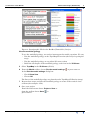
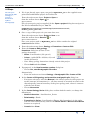
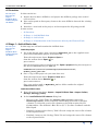
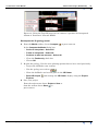
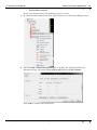
From the Model toolbar, choose Compute
2
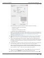
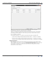
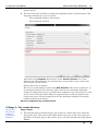
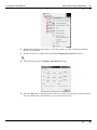
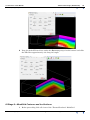
In the Compute the Model dialog box:
3
or press CTRL+M
•
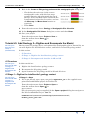
Note that a new series—the LateGranite1—is now available to be computed:
•
Clear the ‘Faults only’ box
•
Series to interpolate—Select All
•
Faults to interpolate—Select All
•
Sections to take into account—Select All
•
Choose OK
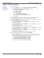
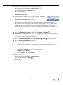
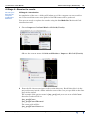
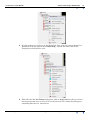
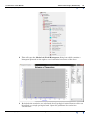
From the Model toolbar, choose from the available plotting options
•
Plot the model settings
or press CTRL+D
•
Plot the model on the current section
•
Plot the model on all sections
Repeat these steps, choosing different options to plot the geology model in
different ways on one or more of the sections.
4
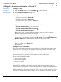
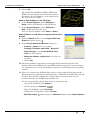
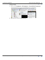
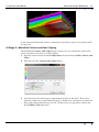
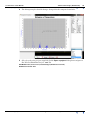
From the Model toolbar, choose Build 3D Formations and Faults
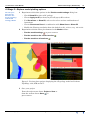
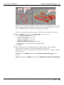
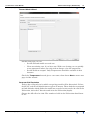
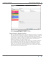
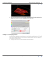
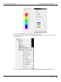
Visualise the revised geology model in the 3D Viewer. Use the Project Explorer to
Show or Hide different formations or units of the 3D geology model.
5
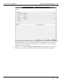
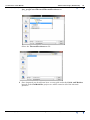
Save your project
From the main menu choose Project > Save or
from the toolbar choose Save
or
press CTRL+S.
J5 Stages 1 and 2—Discussion
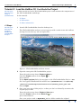
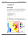
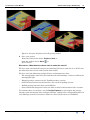
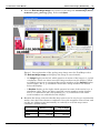
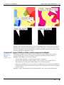
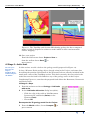
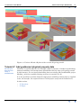
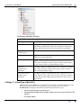
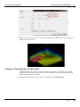
Did your revision produce the expected granite body in the south-east corner of the
project area? To check this you need to plot ‘solid geology’ rather than ‘lines’, and
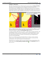
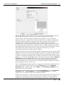
compare your result with Figure 9, below.
If your solid geology map looks like Figure 9a, your 3D geology model is correct; the
LateGranite1 body is a 3D body in the south-east corner of the project.
If your map looks like Figure 9b:
•
what has gone wrong?
•
how did this happen?
•
how do you fix it?
What has gone wrong?
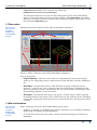
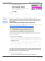
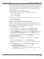
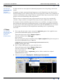
Essentially the problem is the ‘facing direction’ of the geology boundary that you
created to model LateGranite1. If you look closely at the ‘associated orientation data’
that we created, you will see that—for the incorrect case—the dips are steeply
dipping towards the north-west (Figure 9b). This is also the ‘facing’ direction, and, as
a result, the modelled LateGranite1 body lies to the north-west side of the digitised
contact.
Contents Help | Top
© 2013 BRGM & Desmond Fitzgerald & Associates Pty Ltd
| Back |