1
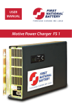
USER
MANUAL
Motive Power Charger FS 3
1
Contents
Warnings3
Installation4
Operating Instructions
6
Front Panel
8
Maintenance/ Service/ Warranty
2
10
Warnings
Keep naked flames away
from batteries on charge
Risk of battery explosion
Be aware of battery fumes
and electrolytes
Do not dispose of batteries
in the garbage
Pb
Electrical hazard exists
inside the charger, do not
remove the side cover
Always recycle lead acid
batteries
Pb
Battery electrolyte is
highly corrosive
Wear eye protection
when working near
batteries
3
Installation: location
Location:
The preferred installation is where the charger(s) can be located on a
shelf, protected against accidental contact with the lift truck, its fork
tynes.
With the charger on a shelf the risk of damage to the charger or battery
cables is greatly reduced.
Avoid placing the charger on the floor next to the lift truck.
4
Installation: wall mounting
Wall mounting options:
Front Mounting Wall Bracket
1. Fix the bracket to the wall using a type of fastener to suit the wall material.
2. Remove the feet.
3. Reuse the feet screws to fasten the charger to the wall bracket.
4. When fitting the battery cable ensure the locking screw is installed.
Side Mounting Wall Bracket
1. Fix the bracket to the wall using a type of fastener to suit the wall material.
2. Remove the feet and the handles.
3. Reuse the feet & handle screws to fasten the charger to the wall bracket. Handles can be discarded if so desired.
4. When fitting the battery cable ensure the locking screw is installed.
Front mounting
Side mounting
Powermite connector
A0135 and socket A3009 or
equivalent
Chargers with a 3 phase mains cable ONLY suit AC power
outlets with a neutral wire 5 pin outlet, such as Powermite
CAT Outlet A0135 shown above, or equivalent .
5
Operating Instructions
1
1. Ensure battery cables and connectors are in good condition
3
4
2
6
3
9
8
7
5
2. Check start/stop switch to “O”
3. Charger plugged in and turned on
4. Charger rating matches battery
5. Plug in the battery
6
6. Set start/stop switch to “I”
7. Red indicating light, battery charging
8. Green indicating light, charge complete
9. Set start/stop switch to “O”
Operating Instructions
1. Before plugging in the battery, check that the battery leads are in good condition.
2. Check that the stop/start rocker switch is set to “O” (off ).
3. Check the charger is plugged into a power point and that the power is turned on.
4. Check that the rating of the on the charger display matches the voltage, Amp hour rating and battery type (flooded or gel) to be charged.
5. Plug in the battery.
6. Set the start/stop switch to “I” (on).
7. Check that the red indicating light illuminates to indicate the charge has commenced.
8. Green indicating light indicates charge complete.
9. Once the charge is complete set the start/stop switch to “O” (off ) and then disconnect the battery.
When waiting for a battery to be connected,
the controller display shows the voltage,
ampere hour capacity and the type of battery
it is programmed to charge, for the operator
to check and ensure the battery to be charged
matches the charger program.
time on charge, charge cycle, and the battery
& cell voltages.
At the end of the charge, the finishing
conditions are diplayed until the battery is
either disconnected, or the Start/Stop switch is
set to Stop.
During the charge cycle, the display indicates
the charge current, ampere hours returned,
The GREEN LED on the controller is illuminated when
the charger is powered up.
7
Front Panel
4
1. Start/ Stop Switch
2. Large Indicator Lights
3. Controller Push-buttons
4. Controller Display
5. Mini USB Port
3
5
1
2
2
4
3 2 1
Display when No Battery
Connected or start/stop
switch set to “O”
5
6
1. RED LED indicates charging
2. AMBER LED indicates charge complete
3. GREEN LED indicates charger is powered up
4. Up Button
5. Enter Button
6. Down Button
Display when Charging
Confg:
Voltage
Amphrs
Battery
Type
Current
Display when Charge Complete
Battery
Display:
Current=
Amphrs=
Charge time=
State=
Batt volt=
Cell volt=
Rolling Display:
Charge time=
Bulk time=
Finish time=
Termination=
Batt volt=
Cell voltFinish volt=
Amphrs=
Note: When a battery is first connected, or at charge complete, the display backlight illuminates automatically;
at any other time pushing any button will illuminate the backlight for a short time.
8
Front Panel
1. Start/ Stop Switch
“O” = Stop Charge
“I” = Start Charge
2. Large Indicator Lights
Red
Green
Status
OnOffCharging
Flashing Off
Minor fault, but charging
OffOnCharge complete
Flashing On
Minor fault, but charge completed
Flashing Flashing
Major fault, charge may be incomplete
3. Controller Push-buttons
To enable equalise charge after the next charge cycle
Plug in the battery but before selecting “I” with the start/stop switch
- Push up button to select “Equalise next cycle”
- Push enter button to allow changing
- Push up button - select “Enable”
- Push enter button to accept change
- Push down button - select “Store”
- Push enter button to “Store”
- Push down button to return to “Connect Battery”
- Select “I” with the start/stop Switch
4. Controller Display
Shows different information depending on the status of the charger, see pages 7 & 8.
5. Mini USB Port
When a MINOR fault is indicated, the charge cycle has been
completed and in most cases can be disregarded. When a MAJOR
fault is indicated, the charge cycle has not been completed and the
occurence MUST be reported to First National Battery Service.
9
Maintenance/ Service/ Warranty
Maintenance
Provided it’s installed correctly in an appropriate location and is not abused, the charger
will require little maintenance. The only requirement is to monitor the air inlet filter at
the front of the charger for dirt build up. The power modules internal to the charger
housing require a good supply of cooling air during the charge cycle. A blocked filter
will affect the cooling ability, and could lead to the charger turning down its maximum
output to prevent overheating of the power modules. An extremely blocked air filter
could cause longer charge times, inability to charge the battery correctly or premature
wear-out of the power modules.
The recommended service interval is 12 months but this will vary depending on the
location of the charger and the number of charge cycles performed. The fans in the
power module only run during the charging and are speed controlled. If the charger
output is small the fans will be working hard with considerable hot air being exhausted
from the rear of the charger. The exhaust air from the rear of the charger should never
be restricted. The intermittent operation of the fans results in a long fan service with no
scheduled replacement of fans being required.
The filter material is an electrostatic polypropylene type that is easy to clean with
compressed air to blow out any dirt & dust build up. Before attempting to clean the
filter it is necessary to remove it from the housing by removing the 4 screws that hold
the front grill on the charger and taking the filter to an appropriate place to clean. The
electrostatic filter provides a good compromise between filtering and clogging, but a
small quantity of dust will enter the power modules during normal operation. A small
quantity of dust in the power modules will generally not cause problems, however
excessive build ups or where the material ingested is corrosive, conductive or wet will
cause issues, however excessive build ups or where the material ingested is corrosive,
conductive or wet will cause issues, resulting in premature “wear-out” of the power
module.
Removing the filter from the housing:
1. Remove the four screws holding the filter grill
from the front of the charger housing.
10
2. Withdraw the filter frame from inside the front of the charger housing.
Maintenance/ Service/ Warranty
Service
Should the charger show both the red & green indications flashing there has been
a serious fault that has prevented the charge cycle being completed. Take note of
the error displayed on the controller display and contact First National Battery for
instructions. Should the red indicator be flashing, but the green on steady, the charge
has been completed satisfactorily but with a minor fault. Contact First National Battery
only should this be occurring on a regular basis.
First National Battery
0800 11 2600 Toll free
Warranty
First National Battery warrants that the product is free from defects in material and
workmanship and agrees to remedy any defect (or at its option replace the product)
for a period of one year from the date of purchase. This warranty covers both parts and
labour. Parts may be replaced under this warranty with new or remanufactured parts.
This warranty will not apply to any product that has been improperly installed, misused,
abused, used in ways for which the product was not designed, altered or repaired in any
way which may affect the performance or reliability of operation, damage sustained by
power surges or electrical storms, or shipping damage, or repaired by any unauthorised
repair centre.
Please contact First National Battery prior to shipping any products for repair. All
shipments must be shipped prepaid and include proof of the date of your original
purchase. Please include your name, address, phone number, email address and brief
description of the problem.
First National Battery makes no other warranties, express or implied, including any
warranty of fitness for a particular purpose. In no event shall First National Battery be
responsible for indirect or consequential damages or lost profits, even if First National
Battery has been advised of the possibility of such damages. First National Battery’s sole
obligation shall be the repair or replacement of the nonconforming product.
11
This User Manual applies to Modular charger FS3 which can
accommodate up to 3 power modules inside. The quantity of power
modules installed and the configuration of the charger is specific to a
particular type and rating of battery, and the chargers can have a single
or three phase AC power supply. Should the charging requirements, or
lift truck change, the charger may under some conditions, need to be
reconfigured by the First National Battery Technician to suit the new
requirement.
HEAD OFFICE:
P.O. Box 182, East London, 5200.
Tel No: + 27 43 706-8200.
Fax No: + 27 43 731-2007
e-mail : [email protected]
MARKETING:
P.O. Box 5015, Benoni South,1502.
Tel No: +27 11 741-3600.
Fax N0 +27 11 421-1625
e-mail: [email protected]
BRANCHES:
Cape Town: Carltonville:
Durban:
Klerksdorp:
Rustenburg:
Port Elizabeth:
(021) 932-6331
(018) 787-5838
(031) 902-4227
(018) 469-2895
(014) 592-8369
(041) 487-2686/7
www.battery.co.za
Proud subsidiary of Metair Investments Ltd.
In the interests of continuing advancement we reserve the right to modify specifications without notice.
MELK DESIGN FS 3 24/04/12
Tollfree 0800 112 600


![Roostloggers [Titley] - An Introductory Manual](http://vs1.manualzilla.com/store/data/005649014_1-8c618e497bb2550a491bca85d50a292e-150x150.png)