1
Installing and Administering Internet
Services
HP 9000 Networking
Edition 8
Manufacturing Part Number: B2355-90685
E1200
U.S.A.
© Copyright 2000, Hewlett-Packard Company.
Legal Notices
The information in this document is subject to change without notice.
Hewlett-Packard makes no warranty of any kind with regard to this
manual, including, but not limited to, the implied warranties of
merchantability and fitness for a particular purpose. Hewlett-Packard
shall not be held liable for errors contained herein or direct, indirect,
special, incidental or consequential damages in connection with the
furnishing, performance, or use of this material.
Warranty. A copy of the specific warranty terms applicable to your
Hewlett-Packard product and replacement parts can be obtained from
your local Sales and Service Office.
Restricted Rights Legend. Use, duplication or disclosure by the U.S.
Government is subject to restrictions as set forth in subparagraph (c) (1)
(ii) of the Rights in Technical Data and Computer Software clause at
DFARS 252.227-7013 for DOD agencies, and subparagraphs (c) (1) and
(c) (2) of the Commercial Computer Software Restricted Rights clause at
FAR 52.227-19 for other agencies.
HEWLETT-PACKARD COMPANY
3000 Hanover Street
Palo Alto, California 94304
U.S.A.
Use of this manual and flexible disk(s) or tape cartridge(s) supplied for
this pack is restricted to this product only. Additional copies of the
programs may be made for security and back-up purposes only. Resale of
the programs in their present form or with alterations, is expressly
prohibited.
Copyright Notices. ©copyright 1983-2000 Hewlett-Packard Company,
all rights reserved.
Reproduction, adaptation, or translation of this document without prior
written permission is prohibited, except as allowed under the copyright
laws.
©copyright 1979, 1980, 1983, 1985-93 Regents of the University of
California
This software is based in part on the Fourth Berkeley Software
Distribution under license from the Regents of the University of
2
California.
©copyright 1980, 1984, 1986 Novell, Inc.
©copyright 1986-1992 Sun Microsystems, Inc.
©copyright 1985-86, 1988 Massachusetts Institute of Technology.
©copyright 1989-93 The Open Software Foundation, Inc.
©copyright 1986 Digital Equipment Corporation.
©copyright 1990 Motorola, Inc.
©copyright 1990, 1991, 1992 Cornell University
©copyright 1989-1991 The University of Maryland
©copyright 1988 Carnegie Mellon University
Trademark Notices UNIX is a registered trademark of The Open
Group.
X Window System is a trademark of the Massachusetts Institute of
Technology.
MS-DOS and Microsoft are U.S. registered trademarks of Microsoft
Corporation.
OSF/Motif is a trademark of the Open Software Foundation, Inc. in the
U.S. and other countries.
3
4
Contents
1. Product Overview
The Internet Services . . . . . . . . . . . . . . . . . . . . . . . . . . . . . . . . . . . . . . . .21
Military Standards and Request for Comment Documents . . . . . . . . . .25
2. Installing and Configuring Internet Services
Installing the Internet Services Software . . . . . . . . . . . . . . . . . . . . . . . .29
Configuring the Name Service Switch . . . . . . . . . . . . . . . . . . . . . . . . . . .30
Default Configuration . . . . . . . . . . . . . . . . . . . . . . . . . . . . . . . . . . . . . .32
Troubleshooting the Name Service Switch . . . . . . . . . . . . . . . . . . . . . .32
Configuring Internet Addresses . . . . . . . . . . . . . . . . . . . . . . . . . . . . . . . .34
To Choose a Name Service . . . . . . . . . . . . . . . . . . . . . . . . . . . . . . . . . . .34
To Edit the /etc/hosts File . . . . . . . . . . . . . . . . . . . . . . . . . . . . . . . . . . .35
To Configure Routes . . . . . . . . . . . . . . . . . . . . . . . . . . . . . . . . . . . . . . . .36
To Change a Host’s IP Address . . . . . . . . . . . . . . . . . . . . . . . . . . . . . . .37
Configuring the Internet Daemon, inetd . . . . . . . . . . . . . . . . . . . . . . . . .39
To Edit the /etc/inetd.conf File. . . . . . . . . . . . . . . . . . . . . . . . . . . . . . . .39
To Edit the /var/adm/inetd.sec File . . . . . . . . . . . . . . . . . . . . . . . . . . . .40
Configuring Logging for the Internet Services . . . . . . . . . . . . . . . . . . . .42
To Configure syslogd . . . . . . . . . . . . . . . . . . . . . . . . . . . . . . . . . . . . . . .42
To Maintain System Log Files . . . . . . . . . . . . . . . . . . . . . . . . . . . . . . . .43
To Configure inetd Connection Logging . . . . . . . . . . . . . . . . . . . . . . . .43
To Configure ftpd Session Logging . . . . . . . . . . . . . . . . . . . . . . . . . . . .44
Configuring ftp. . . . . . . . . . . . . . . . . . . . . . . . . . . . . . . . . . . . . . . . . . . . . .45
Configuring Anonymous ftp Access . . . . . . . . . . . . . . . . . . . . . . . . . . . . .46
To Add User ftp to /etc/passwd . . . . . . . . . . . . . . . . . . . . . . . . . . . . . . .46
To Create the Anonymous ftp Directory . . . . . . . . . . . . . . . . . . . . . . . .46
Configuring ftp with /etc/ftpd/ftpaccess . . . . . . . . . . . . . . . . . . . . . . . . . .50
Enabling/Disabling the ftpaccess File . . . . . . . . . . . . . . . . . . . . . . . . . .50
5
Contents
Configuring Logging for ftp . . . . . . . . . . . . . . . . . . . . . . . . . . . . . . . . . . . 51
Logging ftp Sessions . . . . . . . . . . . . . . . . . . . . . . . . . . . . . . . . . . . . . . . 51
Logging ftp File Transfers . . . . . . . . . . . . . . . . . . . . . . . . . . . . . . . . . . 51
Installing sendmail . . . . . . . . . . . . . . . . . . . . . . . . . . . . . . . . . . . . . . . . .
Installing sendmail on a Standalone System . . . . . . . . . . . . . . . . . . .
Installing sendmail on a Mail Server. . . . . . . . . . . . . . . . . . . . . . . . . .
Installing sendmail on a Mail Client . . . . . . . . . . . . . . . . . . . . . . . . . .
Verifying Your sendmail Installation . . . . . . . . . . . . . . . . . . . . . . . . . .
53
53
54
55
57
Troubleshooting sendmail . . . . . . . . . . . . . . . . . . . . . . . . . . . . . . . . . . . .
Keeping the Aliases Database Up to Date. . . . . . . . . . . . . . . . . . . . . .
Verifying Address Resolution and Aliasing . . . . . . . . . . . . . . . . . . . . .
Verifying Message Delivery . . . . . . . . . . . . . . . . . . . . . . . . . . . . . . . . .
Contacting the sendmail Daemon to Verify Connectivity. . . . . . . . . .
Setting Your Domain Name . . . . . . . . . . . . . . . . . . . . . . . . . . . . . . . . .
Attempting to Start Multiple sendmail Daemons. . . . . . . . . . . . . . . .
Configuring and Reading the sendmail Log . . . . . . . . . . . . . . . . . . . .
Printing and Reading the Mail Queue. . . . . . . . . . . . . . . . . . . . . . . . .
60
60
60
61
62
63
63
64
67
3. Configuring and Administering the BIND Name Service
Overview of the BIND Name Service . . . . . . . . . . . . . . . . . . . . . . . . . . .
Benefits of Using BIND . . . . . . . . . . . . . . . . . . . . . . . . . . . . . . . . . . . .
The DNS Name Space. . . . . . . . . . . . . . . . . . . . . . . . . . . . . . . . . . . . . .
How BIND Works . . . . . . . . . . . . . . . . . . . . . . . . . . . . . . . . . . . . . . . . .
How BIND Resolves Host Names . . . . . . . . . . . . . . . . . . . . . . . . . . . .
73
73
74
76
78
Creating and Registering a New Domain . . . . . . . . . . . . . . . . . . . . . . . . 81
Configuring the Name Service Switch . . . . . . . . . . . . . . . . . . . . . . . . . . 83
Choosing Name Servers for Your Domain . . . . . . . . . . . . . . . . . . . . . . . 84
To Choose the Type of Name Server to Run . . . . . . . . . . . . . . . . . . . . 84
To Choose Which Servers Will Be Master Servers . . . . . . . . . . . . . . . 85
6
Contents
Configuring a Primary Master Name Server. . . . . . . . . . . . . . . . . . . . . .86
To Create the Data Files for a Primary Master Server . . . . . . . . . . . .86
To Set the Default Domain Name . . . . . . . . . . . . . . . . . . . . . . . . . . . . .88
The BIND Configuration File . . . . . . . . . . . . . . . . . . . . . . . . . . . . . . . .88
options Statement . . . . . . . . . . . . . . . . . . . . . . . . . . . . . . . . . . . . . . . . .94
Migrating /etc/named.boot to /etc/named.conf . . . . . . . . . . . .106
The Primary Master Server’s Boot File. . . . . . . . . . . . . . . . . . . . . . . .106
The Primary Master Server’s Cache File . . . . . . . . . . . . . . . . . . . . . .107
The db.127.0.0 File . . . . . . . . . . . . . . . . . . . . . . . . . . . . . . . . . . . . . . . .109
The Primary Master Server’s db.domain Files . . . . . . . . . . . . . . . . . .111
The Primary Master Server’s db.net Files . . . . . . . . . . . . . . . . . . . . .114
To Add a Host to the Domain Data Files . . . . . . . . . . . . . . . . . . . . . .116
To Delete a Host from the Domain Data Files . . . . . . . . . . . . . . . . . .117
Configuring a Secondary Master Name Server . . . . . . . . . . . . . . . . . . .118
Creating Secondary Server Data Files via hosts_to_named . . . . . . .118
To Create the Secondary Master Server’s Data Files Manually . . . .119
To Set the Default Domain Name . . . . . . . . . . . . . . . . . . . . . . . . . . . .120
Configuring a Caching-Only Name Server. . . . . . . . . . . . . . . . . . . . . . .121
Configuring the Resolver to Query a Remote Name Server . . . . . . . . .123
Configuring the Resolver to Set Timeout Values . . . . . . . . . . . . . . . . .125
Configuring Timeout Values using Environment Variables . . . . . . .125
Configuring Timeout Values using the Configuration File . . . . . . . .126
Configuring Timeout Values using APIs . . . . . . . . . . . . . . . . . . . . . . .126
Sample Program With Timeout Values . . . . . . . . . . . . . . . . . . . . . . .127
Starting the Name Server Daemon . . . . . . . . . . . . . . . . . . . . . . . . . . . .128
Verifying the Name Server . . . . . . . . . . . . . . . . . . . . . . . . . . . . . . . . .128
Updating Network-Related Files . . . . . . . . . . . . . . . . . . . . . . . . . . . . . .130
To Update /etc/hosts.equiv and $HOME/.rhosts . . . . . . . . . . . . . . . . .130
To Update /var/adm/inetd.sec and $HOME/.netrc . . . . . . . . . . . . . . .130
7
Contents
To Update /etc/hosts . . . . . . . . . . . . . . . . . . . . . . . . . . . . . . . . . . . . . . 130
Delegating a Subdomain . . . . . . . . . . . . . . . . . . . . . . . . . . . . . . . . . . . . 131
Configuring a Root Name Server. . . . . . . . . . . . . . . . . . . . . . . . . . . . . . 132
Configuring BIND in SAM. . . . . . . . . . . . . . . . . . . . . . . . . . . . . . . . . . . 134
The Logging System . . . . . . . . . . . . . . . . . . . . . . . . . . . . . . . . . . . . . . . . 135
Troubleshooting the BIND Name Server . . . . . . . . . . . . . . . . . . . . . . .
Troubleshooting Tools and Techniques . . . . . . . . . . . . . . . . . . . . . . .
Problem Symptoms . . . . . . . . . . . . . . . . . . . . . . . . . . . . . . . . . . . . . . .
Name Server Problems . . . . . . . . . . . . . . . . . . . . . . . . . . . . . . . . . . . .
Understanding Name Server Debugging Output . . . . . . . . . . . . . . .
Name Server Statistics . . . . . . . . . . . . . . . . . . . . . . . . . . . . . . . . . . . .
136
136
138
140
145
148
4. Installing and Administering sendmail
Deciding Whether to Install sendmail . . . . . . . . . . . . . . . . . . . . . . . . . 156
Installing sendmail . . . . . . . . . . . . . . . . . . . . . . . . . . . . . . . . . . . . . . . .
Installing sendmail on a Standalone System . . . . . . . . . . . . . . . . . .
Installing sendmail on a Mail Server. . . . . . . . . . . . . . . . . . . . . . . . .
Installing sendmail on a Mail Client . . . . . . . . . . . . . . . . . . . . . . . . .
Verifying Your sendmail Installation . . . . . . . . . . . . . . . . . . . . . . . . .
157
157
158
159
161
Creating sendmail Aliases . . . . . . . . . . . . . . . . . . . . . . . . . . . . . . . . . . .
Adding sendmail Aliases to the Alias Database . . . . . . . . . . . . . . . .
Verifying Your sendmail Aliases . . . . . . . . . . . . . . . . . . . . . . . . . . . .
Managing sendmail Aliases with NIS or NIS+ . . . . . . . . . . . . . . . . .
Rewriting the “From” Line on Outgoing Mail . . . . . . . . . . . . . . . . . .
Forwarding Your Own Mail with a .forward File . . . . . . . . . . . . . . .
164
164
168
168
169
170
How sendmail Works . . . . . . . . . . . . . . . . . . . . . . . . . . . . . . . . . . . . . . . 171
Message Structure . . . . . . . . . . . . . . . . . . . . . . . . . . . . . . . . . . . . . . . 171
How sendmail Collects Messages. . . . . . . . . . . . . . . . . . . . . . . . . . . . 172
8
Contents
How sendmail Routes Messages . . . . . . . . . . . . . . . . . . . . . . . . . . . . .172
Default Client-Server Operation . . . . . . . . . . . . . . . . . . . . . . . . . . . . .178
How sendmail Handles Errors . . . . . . . . . . . . . . . . . . . . . . . . . . . . . .180
Sendmail and the LDAP Protocol . . . . . . . . . . . . . . . . . . . . . . . . . . . . . .183
Enabling Address Lookups Using LDAP . . . . . . . . . . . . . . . . . . . . . .183
Modifying the Default sendmail Configuration File . . . . . . . . . . . . . . .185
The sendmail Configuration File . . . . . . . . . . . . . . . . . . . . . . . . . . . . .185
Restarting sendmail . . . . . . . . . . . . . . . . . . . . . . . . . . . . . . . . . . . . . . .186
Forwarding Non-Domain Mail to a Gateway . . . . . . . . . . . . . . . . . . .186
Configuration Options . . . . . . . . . . . . . . . . . . . . . . . . . . . . . . . . . . . . .186
Migrating the sendmail Configuration File . . . . . . . . . . . . . . . . . . . . . .188
Security . . . . . . . . . . . . . . . . . . . . . . . . . . . . . . . . . . . . . . . . . . . . . . . . . .190
Turning Off Standard Security Checks. . . . . . . . . . . . . . . . . . . . . . . .190
Configuring sendmail to Reject Unsolicited Mail . . . . . . . . . . . . . . . . .194
Enabling “Anti-Spamming” Capability . . . . . . . . . . . . . . . . . . . . . . . .194
Accepting and Rejecting Mail From Particular Senders . . . . . . . . . .194
Preventing Unauthorized Mail Relay Usage . . . . . . . . . . . . . . . . . . .195
Sendmail Validation . . . . . . . . . . . . . . . . . . . . . . . . . . . . . . . . . . . . . . .197
Sendmail Anti-Spamming Security. . . . . . . . . . . . . . . . . . . . . . . . . . .197
Enabling Sendmail Anti-Spamming Security Features . . . . . . . . . . .198
Using the Access Database to Allow or Reject Mail Messages . . . . .198
Relaying Capability . . . . . . . . . . . . . . . . . . . . . . . . . . . . . . . . . . . . . . .200
Validating Senders . . . . . . . . . . . . . . . . . . . . . . . . . . . . . . . . . . . . . . . .201
Header Checking . . . . . . . . . . . . . . . . . . . . . . . . . . . . . . . . . . . . . . . . .203
Turning off Virtual Interfaces. . . . . . . . . . . . . . . . . . . . . . . . . . . . . . . . .206
Troubleshooting sendmail . . . . . . . . . . . . . . . . . . . . . . . . . . . . . . . . . . . .207
Keeping the Aliases Database Up to Date . . . . . . . . . . . . . . . . . . . . .207
Verifying Address Resolution and Aliasing. . . . . . . . . . . . . . . . . . . . .208
Verifying Message Delivery . . . . . . . . . . . . . . . . . . . . . . . . . . . . . . . . .208
9
Contents
Contacting the sendmail Daemon to Verify Connectivity. . . . . . . . .
Setting Your Domain Name . . . . . . . . . . . . . . . . . . . . . . . . . . . . . . . .
Attempting to Start Multiple sendmail Daemons. . . . . . . . . . . . . . .
Configuring and Reading the sendmail Log . . . . . . . . . . . . . . . . . . .
Printing and Reading the Mail Queue. . . . . . . . . . . . . . . . . . . . . . . .
209
210
210
211
214
5. Configuring TFTP and BOOTP Servers
Chapter Overview . . . . . . . . . . . . . . . . . . . . . . . . . . . . . . . . . . . . . . . . . 219
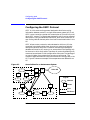
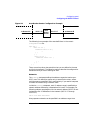
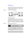
How BOOTP Works . . . . . . . . . . . . . . . . . . . . . . . . . . . . . . . . . . . . . . . . 220
Address Determination and Bootfile Selection . . . . . . . . . . . . . . . . . 220
File Transfer . . . . . . . . . . . . . . . . . . . . . . . . . . . . . . . . . . . . . . . . . . . . 222
Booting RMP Clients . . . . . . . . . . . . . . . . . . . . . . . . . . . . . . . . . . . . . . . 223
Configuring the TFTP Server . . . . . . . . . . . . . . . . . . . . . . . . . . . . . . . . 225
Procedure for Configuring tftpd . . . . . . . . . . . . . . . . . . . . . . . . . . . . . 225
Verify Your tftpd Installation . . . . . . . . . . . . . . . . . . . . . . . . . . . . . . . 226
Configuring the BOOTP Server. . . . . . . . . . . . . . . . . . . . . . . . . . . . . . . 228
Procedure for Configuring bootpd . . . . . . . . . . . . . . . . . . . . . . . . . . . 228
Verify Your bootpd Installation . . . . . . . . . . . . . . . . . . . . . . . . . . . . . 229
Adding Client or Relay Information . . . . . . . . . . . . . . . . . . . . . . . . . . .
Collecting Client Information. . . . . . . . . . . . . . . . . . . . . . . . . . . . . . .
Collecting Relay Information . . . . . . . . . . . . . . . . . . . . . . . . . . . . . . .
Understanding Boot File Configurations. . . . . . . . . . . . . . . . . . . . . .
Parameter Tags and Descriptions . . . . . . . . . . . . . . . . . . . . . . . . . . .
Examples of Adding BOOTP Clients . . . . . . . . . . . . . . . . . . . . . . . . .
230
230
230
231
232
234
Command Options for Using TFTP. . . . . . . . . . . . . . . . . . . . . . . . . . . . 238
Troubleshooting BOOTP and TFTP Servers . . . . . . . . . . . . . . . . . . . .
Helpful Configuration Changes . . . . . . . . . . . . . . . . . . . . . . . . . . . . .
Common bootpd Problems . . . . . . . . . . . . . . . . . . . . . . . . . . . . . . . . .
Common tftpd Problems . . . . . . . . . . . . . . . . . . . . . . . . . . . . . . . . . . .
10
239
239
239
243
Contents
Error Logging . . . . . . . . . . . . . . . . . . . . . . . . . . . . . . . . . . . . . . . . . . . .245
6. Dynamic Host Configuration Protocol (DHCP)
Overview . . . . . . . . . . . . . . . . . . . . . . . . . . . . . . . . . . . . . . . . . . . . . . . . .253
Benefits of Using DHCP. . . . . . . . . . . . . . . . . . . . . . . . . . . . . . . . . . . .253
DHCP Components and Concepts . . . . . . . . . . . . . . . . . . . . . . . . . . . . .254
DHCP Servers. . . . . . . . . . . . . . . . . . . . . . . . . . . . . . . . . . . . . . . . . . . .254
DHCP Clients . . . . . . . . . . . . . . . . . . . . . . . . . . . . . . . . . . . . . . . . . . . .254
DHCP Leases . . . . . . . . . . . . . . . . . . . . . . . . . . . . . . . . . . . . . . . . . . . .255
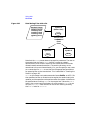
DHCP Transactions: Basic Operation. . . . . . . . . . . . . . . . . . . . . . . . .255
Dynamic Updates . . . . . . . . . . . . . . . . . . . . . . . . . . . . . . . . . . . . . . . . . .258
Dynamic DNS Server Update Pre-Requisites. . . . . . . . . . . . . . . . . . .258
Configuring the DHCP Server to Perform Dynamic Updates . . . . . .259
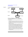
Configuration Overview . . . . . . . . . . . . . . . . . . . . . . . . . . . . . . . . . . . . .260
DHCP Device and Pool Group Configuration . . . . . . . . . . . . . . . . . . .260
DHCP Individual Device Configuration . . . . . . . . . . . . . . . . . . . . . . .263
DHCP Configuration through BOOTP Relay Agent . . . . . . . . . . . . .264
Configuring PING Timeouts . . . . . . . . . . . . . . . . . . . . . . . . . . . . . . . .266
Configuring DHCP. . . . . . . . . . . . . . . . . . . . . . . . . . . . . . . . . . . . . . . . . .267
Setting Up the Broadcast Address . . . . . . . . . . . . . . . . . . . . . . . . . . .267
Preparing to Configure a DHCP Server . . . . . . . . . . . . . . . . . . . . . . .267
Configuring a DHCP Server to Distribute IP Addresses to
Groups of Devices . . . . . . . . . . . . . . . . . . . . . . . . . . . . . . . . . . . . . . . .268
Configuring a DHCP Server to Distribute IP Addresses to
Individual Devices . . . . . . . . . . . . . . . . . . . . . . . . . . . . . . . . . . . . . . .270
Configuring a DHCP Server to Distribute IP Addresses
through a BOOTP Relay Agent . . . . . . . . . . . . . . . . . . . . . . . . . . . . .271
Enabling DHCP on a System Not Initially Configured with
DHCP . . . . . . . . . . . . . . . . . . . . . . . . . . . . . . . . . . . . . . . . . . . . . . . . .273
bootptab and dhcptab Files . . . . . . . . . . . . . . . . . . . . . . . . . . . . . . . . .273
11
Contents
Configuring DHCP to Deny Address Allocation to
Specific Clients . . . . . . . . . . . . . . . . . . . . . . . . . . . . . . . . . . . . . . . . . 274
Monitoring and Troubleshooting DHCP Operations . . . . . . . . . . . . . .
Troubleshooting Techniques. . . . . . . . . . . . . . . . . . . . . . . . . . . . . . . .
DHCP Troubleshooting Tools . . . . . . . . . . . . . . . . . . . . . . . . . . . . . . .
Callbacks . . . . . . . . . . . . . . . . . . . . . . . . . . . . . . . . . . . . . . . . . . . . . . .
275
275
277
278
7. Configuring the Network Time Protocol (NTP)
Getting Started with NTP . . . . . . . . . . . . . . . . . . . . . . . . . . . . . . . . . . .
Equipment Needed for NTP . . . . . . . . . . . . . . . . . . . . . . . . . . . . . . . .
Choosing the Source of Time . . . . . . . . . . . . . . . . . . . . . . . . . . . . . . .
Location of Time Source . . . . . . . . . . . . . . . . . . . . . . . . . . . . . . . . . . .
Back-up Time Servers. . . . . . . . . . . . . . . . . . . . . . . . . . . . . . . . . . . . .
Configuring Your Primary NTP Server . . . . . . . . . . . . . . . . . . . . . . .
283
283
284
287
296
296
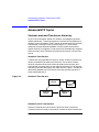
Advanced NTP Topics . . . . . . . . . . . . . . . . . . . . . . . . . . . . . . . . . . . . . .
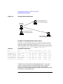
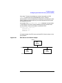
Stratum Levels and Time Server Hierarchy . . . . . . . . . . . . . . . . . . .
Planning a Multiple-Server NTP Configuration . . . . . . . . . . . . . . . .
Configuring NTP using the Configuration File . . . . . . . . . . . . . . . . .
Starting and Stopping xntpd . . . . . . . . . . . . . . . . . . . . . . . . . . . . . . .
Using ntpq to Query Systems Running xntpd. . . . . . . . . . . . . . . . . .
298
298
300
301
309
310
Troubleshooting ntp . . . . . . . . . . . . . . . . . . . . . . . . . . . . . . . . . . . . . . . .
To Find Out if xntpd is Running . . . . . . . . . . . . . . . . . . . . . . . . . . . .
NTP Associations . . . . . . . . . . . . . . . . . . . . . . . . . . . . . . . . . . . . . . . .
Query with Debug Option. . . . . . . . . . . . . . . . . . . . . . . . . . . . . . . . . .
Error Messages . . . . . . . . . . . . . . . . . . . . . . . . . . . . . . . . . . . . . . . . . .
Common Problems . . . . . . . . . . . . . . . . . . . . . . . . . . . . . . . . . . . . . . .
Reporting Problems. . . . . . . . . . . . . . . . . . . . . . . . . . . . . . . . . . . . . . .
313
313
313
314
314
315
317
12
Contents
8. Configuring gated
Overview . . . . . . . . . . . . . . . . . . . . . . . . . . . . . . . . . . . . . . . . . . . . . . . . .321
Advantages . . . . . . . . . . . . . . . . . . . . . . . . . . . . . . . . . . . . . . . . . . . . . .321
When to Use gated . . . . . . . . . . . . . . . . . . . . . . . . . . . . . . . . . . . . . . . .322
Protocols . . . . . . . . . . . . . . . . . . . . . . . . . . . . . . . . . . . . . . . . . . . . . . . .322
Configuration Overview . . . . . . . . . . . . . . . . . . . . . . . . . . . . . . . . . . . . .326
How to Configure gated . . . . . . . . . . . . . . . . . . . . . . . . . . . . . . . . . . . .327
Converting the Configuration File from 3.0 to 3.5 . . . . . . . . . . . . . . .329
Configuring the RIP Protocol . . . . . . . . . . . . . . . . . . . . . . . . . . . . . . . . .331
Configuration Options . . . . . . . . . . . . . . . . . . . . . . . . . . . . . . . . . . . . .331
Simple RIP Configuration . . . . . . . . . . . . . . . . . . . . . . . . . . . . . . . . . .332
RIP Protocol Statement . . . . . . . . . . . . . . . . . . . . . . . . . . . . . . . . . . . .333
Controlling RIP Traffic. . . . . . . . . . . . . . . . . . . . . . . . . . . . . . . . . . . . .336
Large RIP Configuration Example . . . . . . . . . . . . . . . . . . . . . . . . . . .336
Configuring the OSPF Protocol. . . . . . . . . . . . . . . . . . . . . . . . . . . . . . . .340
Planning Your OSPF Configuration . . . . . . . . . . . . . . . . . . . . . . . . . .342
Enabling OSPF . . . . . . . . . . . . . . . . . . . . . . . . . . . . . . . . . . . . . . . . . . .344
Defining Areas . . . . . . . . . . . . . . . . . . . . . . . . . . . . . . . . . . . . . . . . . . .344
Defining Backbones . . . . . . . . . . . . . . . . . . . . . . . . . . . . . . . . . . . . . . .355
Authentication . . . . . . . . . . . . . . . . . . . . . . . . . . . . . . . . . . . . . . . . . . .357
Cost . . . . . . . . . . . . . . . . . . . . . . . . . . . . . . . . . . . . . . . . . . . . . . . . . . . .359
AS External Routes (AS Boundary Routers Only) . . . . . . . . . . . . . . .360
Sample OSPF Configuration . . . . . . . . . . . . . . . . . . . . . . . . . . . . . . . .362
Accessing the OSPF MIB . . . . . . . . . . . . . . . . . . . . . . . . . . . . . . . . . . .366
Configuring the Router Discovery Protocol (RDP). . . . . . . . . . . . . . . . .367
The RDP Server . . . . . . . . . . . . . . . . . . . . . . . . . . . . . . . . . . . . . . . . . .367
The RDP Client. . . . . . . . . . . . . . . . . . . . . . . . . . . . . . . . . . . . . . . . . . .368
Customizing Routes. . . . . . . . . . . . . . . . . . . . . . . . . . . . . . . . . . . . . . . . .370
Specifying a Default Router. . . . . . . . . . . . . . . . . . . . . . . . . . . . . . . . .370
13
Contents
Installing Static Routes . . . . . . . . . . . . . . . . . . . . . . . . . . . . . . . . . . . 370
Setting Interface States . . . . . . . . . . . . . . . . . . . . . . . . . . . . . . . . . . . 371
Specifying Tracing Options . . . . . . . . . . . . . . . . . . . . . . . . . . . . . . . . . . 372
Specifying Route Preference . . . . . . . . . . . . . . . . . . . . . . . . . . . . . . . . . 374
Importing and Exporting Routes. . . . . . . . . . . . . . . . . . . . . . . . . . . . . .
import Statements . . . . . . . . . . . . . . . . . . . . . . . . . . . . . . . . . . . . . . .
export Statements . . . . . . . . . . . . . . . . . . . . . . . . . . . . . . . . . . . . . . . .
Examples of import and export Statements . . . . . . . . . . . . . . . . . . .
377
377
377
378
Starting gated. . . . . . . . . . . . . . . . . . . . . . . . . . . . . . . . . . . . . . . . . . . . . 379
To Find Out if gated is Running. . . . . . . . . . . . . . . . . . . . . . . . . . . . . 379
Troubleshooting gated . . . . . . . . . . . . . . . . . . . . . . . . . . . . . . . . . . . . . . 381
Troubleshooting Tools and Techniques . . . . . . . . . . . . . . . . . . . . . . . 381
Common Problems . . . . . . . . . . . . . . . . . . . . . . . . . . . . . . . . . . . . . . . 383
9. Configuring mrouted
Overview of Multicasting . . . . . . . . . . . . . . . . . . . . . . . . . . . . . . . . . . . .
DVMRP . . . . . . . . . . . . . . . . . . . . . . . . . . . . . . . . . . . . . . . . . . . . . . . .
IP Multicast Addresses . . . . . . . . . . . . . . . . . . . . . . . . . . . . . . . . . . . .
Multicast Groups. . . . . . . . . . . . . . . . . . . . . . . . . . . . . . . . . . . . . . . . .
391
391
392
393
Configuring mrouted . . . . . . . . . . . . . . . . . . . . . . . . . . . . . . . . . . . . . . . 395
Configuration File Commands . . . . . . . . . . . . . . . . . . . . . . . . . . . . . . 395
Starting mrouted . . . . . . . . . . . . . . . . . . . . . . . . . . . . . . . . . . . . . . . . . . 399
Verifying mrouted Operation. . . . . . . . . . . . . . . . . . . . . . . . . . . . . . . . . 400
Displaying mrouted Routing Tables . . . . . . . . . . . . . . . . . . . . . . . . . . . 401
Multicast Routing Support Tools. . . . . . . . . . . . . . . . . . . . . . . . . . . . . .
mrinfo . . . . . . . . . . . . . . . . . . . . . . . . . . . . . . . . . . . . . . . . . . . . . . . . .
map-mbone . . . . . . . . . . . . . . . . . . . . . . . . . . . . . . . . . . . . . . . . . . . . .
netstat . . . . . . . . . . . . . . . . . . . . . . . . . . . . . . . . . . . . . . . . . . . . . . . . .
14
403
403
403
403
Contents
Sources for Additional Information . . . . . . . . . . . . . . . . . . . . . . . . . . . .404
RFC documents . . . . . . . . . . . . . . . . . . . . . . . . . . . . . . . . . . . . . . . . . .404
Other Documents . . . . . . . . . . . . . . . . . . . . . . . . . . . . . . . . . . . . . . . . .404
10. Using rdist
Overview . . . . . . . . . . . . . . . . . . . . . . . . . . . . . . . . . . . . . . . . . . . . . . . . .407
Setting Up remsh. . . . . . . . . . . . . . . . . . . . . . . . . . . . . . . . . . . . . . . . . . .409
Authentication for remsh and rexec Services . . . . . . . . . . . . . . . . . . .409
Creating the Distfile . . . . . . . . . . . . . . . . . . . . . . . . . . . . . . . . . . . . . . . .412
Variable Definitions . . . . . . . . . . . . . . . . . . . . . . . . . . . . . . . . . . . . . . .412
File Distribution Commands . . . . . . . . . . . . . . . . . . . . . . . . . . . . . . . .413
Changed Files List Commands . . . . . . . . . . . . . . . . . . . . . . . . . . . . . .417
Starting rdist . . . . . . . . . . . . . . . . . . . . . . . . . . . . . . . . . . . . . . . . . . . . . .418
Example Output on the Master Host . . . . . . . . . . . . . . . . . . . . . . . . .419
Authentication for remsh and rexec Sercvices . . . . . . . . . . . . . . . . . .420
Troubleshooting rdist . . . . . . . . . . . . . . . . . . . . . . . . . . . . . . . . . . . . . . .422
11. Secure Internet Services
Overview of the Secure Internet Services . . . . . . . . . . . . . . . . . . . . . . .427
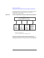
Overview of the Secure Environment and the Kerberos V5 Protocol . .429
Components of the Secure Environment. . . . . . . . . . . . . . . . . . . . . . .430
A Simplified Description of the Kerberos V5 Protocol . . . . . . . . . . . .431
Related Terms and Concepts . . . . . . . . . . . . . . . . . . . . . . . . . . . . . . . .433
Secure Environment Configurations . . . . . . . . . . . . . . . . . . . . . . . . . .437
Configuration and Kerberos Version Interoperability
Requirements. . . . . . . . . . . . . . . . . . . . . . . . . . . . . . . . . . . . . . . . . . . . .443
File Requirements . . . . . . . . . . . . . . . . . . . . . . . . . . . . . . . . . . . . . . . .443
KDC Requirements . . . . . . . . . . . . . . . . . . . . . . . . . . . . . . . . . . . . . . .446
Security Client Requirements . . . . . . . . . . . . . . . . . . . . . . . . . . . . . . .446
15
Contents
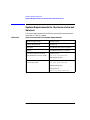
System Requirements for the Secure Internet Services . . . . . . . . . . . 448
Configuring the Secure Internet Services. . . . . . . . . . . . . . . . . . . . . . . 449
The KDC . . . . . . . . . . . . . . . . . . . . . . . . . . . . . . . . . . . . . . . . . . . . . . . 449
Security Clients. . . . . . . . . . . . . . . . . . . . . . . . . . . . . . . . . . . . . . . . . . 449
Migrating Version 5 Beta 4 Files to Version 5 Release 1.0 . . . . . . . . . 451
Enabling the Secure Internet Services Mechanism . . . . . . . . . . . . . . . 452
Disabling the Secure Internet Services Mechanism . . . . . . . . . . . . . . 453
Checking the Current Authentication Mechanism . . . . . . . . . . . . . . . 454
Verifying the Secure Internet Services . . . . . . . . . . . . . . . . . . . . . . . . . 455
Secure Environment Checklist. . . . . . . . . . . . . . . . . . . . . . . . . . . . . . 455
Verifying Usage of Secure Internet Services . . . . . . . . . . . . . . . . . . . 456
Using the Secure Internet Services. . . . . . . . . . . . . . . . . . . . . . . . . . . .
Overview of the User’s Session. . . . . . . . . . . . . . . . . . . . . . . . . . . . . .
Bypassing and Enforcing Kerberos Authentication . . . . . . . . . . . . .
Other Comments on Using the Secure Internet Services. . . . . . . . .
457
457
458
458
Troubleshooting the Secure Internet Services . . . . . . . . . . . . . . . . . . .
The Verification Checklist . . . . . . . . . . . . . . . . . . . . . . . . . . . . . . . . .
Security-related Error Messages . . . . . . . . . . . . . . . . . . . . . . . . . . . .
Common Problems . . . . . . . . . . . . . . . . . . . . . . . . . . . . . . . . . . . . . . .
460
460
460
460
Sources for Additional Information. . . . . . . . . . . . . . . . . . . . . . . . . . . .
Additional HP Documentation . . . . . . . . . . . . . . . . . . . . . . . . . . . . . .
Relevant Man Pages . . . . . . . . . . . . . . . . . . . . . . . . . . . . . . . . . . . . . .
Related RFCs. . . . . . . . . . . . . . . . . . . . . . . . . . . . . . . . . . . . . . . . . . . .
461
461
461
461
12. Troubleshooting Internet Services
Chapter Overview . . . . . . . . . . . . . . . . . . . . . . . . . . . . . . . . . . . . . . . . . 465
Characterizing the Problem. . . . . . . . . . . . . . . . . . . . . . . . . . . . . . . . . . 466
16
Contents
Diagnostic Tools Summary . . . . . . . . . . . . . . . . . . . . . . . . . . . . . . . . . . .468
Diagnosing Repeater and Gateway Problems . . . . . . . . . . . . . . . . . . . .469
Flowchart Format . . . . . . . . . . . . . . . . . . . . . . . . . . . . . . . . . . . . . . . . . .471
Troubleshooting the Internet Services . . . . . . . . . . . . . . . . . . . . . . . . . .472
Error Messages . . . . . . . . . . . . . . . . . . . . . . . . . . . . . . . . . . . . . . . . . . .472
Services Checklist. . . . . . . . . . . . . . . . . . . . . . . . . . . . . . . . . . . . . . . . .473
Flowchart 1. Checking for a Server . . . . . . . . . . . . . . . . . . . . . . . . . . .474
Flowchart 2. Security for telnet and ftp . . . . . . . . . . . . . . . . . . . . . . .479
Flowchart 3. Security for Berkeley Services . . . . . . . . . . . . . . . . . . .482
Reporting Problems to Your Hewlett-Packard Support Contact. . . . . .485
17
Contents
18
1
Product Overview
The HP 9000 Internet Services enable your HP 9000 computer to
transfer files, log into remote hosts, execute commands remotely, and
exchange mail with remote hosts on the network. The Internet Services
product was previously called the ARPA Services.
19
Product Overview
A link product, such as LAN/9000 or X.25/9000, must be installed for the
Internet Services to function. The link product provides the hardware
and software needed for communication by an HP 9000 computer over an
IEEE 802.3, Ethernet Local Area Network, or X.25 packet switch
network. NS and NFS Services also require link software and can run
concurrently on the same node with the Internet Services.
The information in this manual applies to all HP 9000 computer systems
unless specifically noted otherwise.
20
Chapter 1
Product Overview
The Internet Services
The Internet Services
The HP 9000 Internet Services product combines services developed by
the University of California at Berkeley (UCB), Cornell University, Merit
Network, Inc., Carnegie-Mellon University (CMU), Hewlett-Packard,
Massachusetts Institute of Technology (MIT), Internet Software
Consortium, and other public domain sources.
ARPA Services include the set of services developed by UCB for the
Advanced Research Projects Agency (ARPA): ftp and telnet. ARPA
services are used to communicate with HP-UX, UNIX, and non-UNIX
systems.
Berkeley Services include the set of services developed by UCB to
implement UCB protocols: BIND, sendmail, finger, the rexec library,
rcp, rlogin, remsh, ruptime, rwho, and rdist. Berkeley Services are
used to communicate with HP-UX or UNIX systems.
The Internet Services product also contains several other services:
BOOTP, tftp, rbootd, NTP, and DDFA.
We strongly recommend that you also see the following books for more
detailed technical and conceptual information:
• For the Internet Services, see TCP/IP Network Administration by
Craig Hunt, published by O’Reilly and Associates.
• For BIND, see DNS and BIND, by Paul Albitz and Cricket Liu,
published by O’Reilly and Associates, Inc.
• For sendmail, see sendmail, 2nd edition, by Bryan Costales with Eric
Allman and Neil Richert, published by O’Reilly and Associates, Inc.
You also can visit the Worldwide Web (WWW) site for sendmail:
http://www.sendmail.org
Note that you can get information about the O’Reilly books (including
retail outlets where you can buy them, as well as how to order them
directly from O’Reilly) by visiting the O’Reilly WWW site:
http://www.ora.com
Once you are at the O’Reilly site, look in the catalog, under the category
“System and Network Administration.” The above books are listed under
“Network Administration.”
Chapter 1
21
Product Overview
The Internet Services
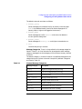
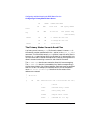
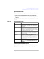
Table 1-1 lists the Internet Services.
Table 1-1
The Internet Services
ftp
Copies files among hosts on the network that support Internet Services. For
more information, see “Installing and Configuring Internet Services” on
page 27 or type man 1 ftp or man 1M ftpd.
telnet
Allows you to log onto a remote host that supports Internet Services. For
more information, see “Installing and Configuring Internet Services” on
page 27 or type man 1 telnet or man 1M telenetd.
sendmail
Works with your network’s mailers (for example, elm and mailx) to
perform internetwork mail routing among UNIX and non-UNIX hosts on
the network. For more information, see “Installing and Administering
sendmail” on page 153 or type man 1M sendmail.
BIND
Implements the Domain Name System (DNS). The Berkeley Internet
Name Domain (BIND) Service is a distributed database service that
resolves host names and facilitates internetwork mail. For more
information, see “Configuring and Administering the BIND Name
Service” on page 71 or type man 1M named.
finger
Allows users to look up information about other users on the network. For
more information, see “Installing and Configuring Internet Services” on
page 27 or type man 1 finger or man 1M fingerd.
BOOTP
Allows some diskless systems, such as the HP 700/X terminal, to load
network and configuration parameters from a server on the network. For
more information, see “Configuring TFTP and BOOTP Servers” on page
217 or type man 1M bootpd.
tftp
Used with bootp to allow some diskless systems, such as the HP 700/X
terminal, to transfer files containing bootstrap code, fonts, or other
configuration information. For more information, see “Configuring TFTP
and BOOTP Servers” on page 217 or type man 1 tftp or man 1M
tftpd.
gated
Dynamically determines routing over internets from one node to another.
For more information, see “Configuring gated” on page 319 or type man
1M gated.
mrouted
Implements the Distance-Vector Multicast Routing Protocol (DVMRP) for
routing IP multicast datagrams. For more information, see “Configuring
mrouted” on page 389 or type man 1M mrouted.
22
Chapter 1
Product Overview
The Internet Services
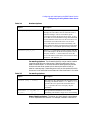
Table 1-1
The Internet Services
NTP
Maintains the local clock on an HP-UX workstation in agreement with
Internet-standard time servers. For more information, see “Configuring the
Network Time Protocol (NTP)” on page 281, or type man 1M xntpd.
rexec
A library routine used to execute commands on a remote UNIX host on the
network. For more information, see “Installing and Configuring Internet
Services” on page 27 or type man 3N rexec or man 1M rexecd.
rcp
Allows you to transfer files between UNIX hosts on the network. For more
information, see “Installing and Configuring Internet Services” on page 27
or type man 1 rcp.
rlogin
Allows you to log onto a remote UNIX host. For more information, see
“Installing and Configuring Internet Services” on page 27 or type man 1
rlogin or man 1M rlogind.
remsh
Allows you to execute commands on a remote UNIX host. remsh is the
same command as rsh in 4.3 BSD. For more information, see “Installing
and Configuring Internet Services” on page 27, or type man 1 remsh or
man 1M remshd.
ruptime
Lists information about specified UNIX nodes that are running the rwhod
daemon. ruptime is not supported over X.25 networks or networks using
the PPL (SLIP) product. For more information, see “Installing and
Configuring Internet Services” on page 27 or type man 1 ruptime or
man 1M rwhod.
rwho
Lists information about specified UNIX nodes that are running the rwhod
daemon. rwho is not supported over X.25 networks or networks using the
PPL (SLIP) product. For more information, see “Installing and Configuring
Internet Services” on page 27 or type man 1 rwho or man 1M rwhod.
rdist
Distributes and maintains identical copies of files across multiple hosts. For
more information, see “Using rdist” on page 405 or type man 1 rdist.
rbootd
RMP is an HP-proprietary boot and file transfer protocol used in early
workstations and in the Datacommunications and Terminal Controllers
(DTC/9000). For more information, see “Configuring TFTP and BOOTP
Servers” on page 217 or type man 1M rbootd.
whois
Lists information about specified people and organizations listed in the
Network Information Center (NIC) database. A direct socket connection to
the NIC is required. For more information, type man 1 whois.
Chapter 1
23
Product Overview
The Internet Services
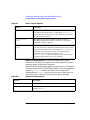
Table 1-1
The Internet Services
DDFA
Allows access from HP-UX systems and user-written applications to HP
DTCs. For more information, see the DTC Device File Access Utilities
manual.
Secure Internet
Services
An optionally enabled mechanism that incorporates Kerberos V5 Release
1.0 authentication and authorization for the following services: ftp, rcp,
remsh, rlogin, and telnet. For more information, see “Secure Internet
Services” on page 425.
24
Chapter 1
Product Overview
Military Standards and Request for Comment Documents
Military Standards and Request for Comment
Documents
To obtain information about available MIL-STD specifications, contact
the following:
Department of the Navy
Naval Publications and Forms Center
5801 Tabor Avenue
Philadelphia, PA 19120-5099
To obtain information about available RFCs, contact the following:
Government Systems, Inc.
Attn: Network Information Center
14200 Park Meadow Drive
Suite 200
Chantilly, VA 22021
phone: (703) 802-8400
You can also obtain copies of RFCs by anonymous ftp, from
venera.isi.edu. The RFCs are in the directory in-notes under the
anonymous ftp directory. The RFC files are called rfc###.txt, where
### is the number of the RFC.
Also, the following RFCs are located in the /usr/share/doc directory:
• 1034: “Domain Names—Concepts and Facilities”
• 1035: “Domain Names—Implementation and Specification”
• 1535: “A Security Problem and Proposed Correction With Widely
Deployed DNS Software”
Chapter 1
25
Product Overview
Military Standards and Request for Comment Documents
26
Chapter 1
2
Installing and Configuring
Internet Services
This chapter describes how to install the Internet Services and configure
them for your system. It contains the following sections:
27
Installing and Configuring Internet Services
• “Installing the Internet Services Software” on page 29
• “Configuring the Internet Daemon, inetd” on page 39
• “Configuring Logging for the Internet Services” on page 42
28
Chapter 2
Installing and Configuring Internet Services
Installing the Internet Services Software
Installing the Internet Services Software
Before you begin to install the software, make sure you have the correct
operating system on your computer. The HP-UX operating system, the
required link software, and the Internet Services software must all be
the same version. You can check your HP-UX operating system version
with the uname -r command.
Use the HP-UX Software Distributor (SD) to install the Internet Services
file set. Issue the following command to start the SD swinstall utility:
/usr/sbin/swinstall
The Software Distributor is documented in Managing HP-UX Software
with SD-UX.
Chapter 2
29
Installing and Configuring Internet Services
Configuring the Name Service Switch
Configuring the Name Service Switch
The Name Service Switch determines where your system will look for the
information that is traditionally stored in the following files:
/etc/mail/aliases
AutoFS maps (like /etc/auto_master and /etc/auto_home)
/etc/group
/etc/hosts
/etc/netgroup
/etc/networks
/etc/passwd
/etc/protocols
/etc/publickey
/etc/rpc
/etc/services
For all types of information except host information, you can configure
your system to use NIS (one of the NFS Services), NIS+ (the next
generation of NIS), or the local /etc file, in any order. However, we
recommend that you do not configure your system to use both NIS and
NIS+.
For host information, you can configure your system to use BIND (DNS),
NIS, NIS+, or the /etc/hosts file. As mentioned above, we recommend
that you do not configure your system to use both NIS and NIS+.
The default Name Service Switch configuration is adequate for most
installations, so you probably do not have to change it. The default
configuration is explained in “Default Configuration” on page 32.
Beginning with the earlier HP-UX 10.30 release, the Name Service
Switch has a different default behavior from the Name Service Switch in
previous releases. If you have been using the pre-10.30 default Name
Service Switch configuration (or if you do not have an
/etc/nsswitch.conf file), and you want your host to continue to have
that same pre-10.30 behavior, copy the /etc/nsswitch.hp_defaults
file to /etc/nsswitch.conf. See “Default Configuration” on page 32.
30
Chapter 2
Installing and Configuring Internet Services
Configuring the Name Service Switch
Also, for more information about the Name Service Switch configuration
files supplied in the /etc directory, see Installing and Administering
NFS Services.
The ability to consult more than one name service for host information is
often called hostname fallback. The Name Service Switch provides
client-side hostname fallback, because it is incorporated into
client-side programs (for example, gethostbyname), which request host
information.
The Network Information Service (NIS), one of the NFS Services, allows
you to configure a server-side hostname fallback. This feature causes
the NIS or NIS+ server to query BIND when it fails to find requested
host information in its database. The NIS or NIS+ server then returns
the host information to the client through NIS or NIS+. This server-side
hostname fallback is intended for use with clients like PCs that do not
have a feature like the Name Service Switch. Hewlett-Packard
recommends that you use the Name Service Switch if possible, instead of
the server-side hostname fallback provided by NIS and NIS+. For more
information about the NIS server-side hostname fallback, see Installing
and Administering NFS Services.
NOTE
Configuring the Name Service Switch is a separate task from configuring
the name services themselves. You must also configure the name services
before you can use them. The Name Service Switch just determines
which name services are queried and in what order.
For more information about configuring the Name Service Switch,
including the syntax of the configuration file and customizing your
configuration, see Installing and Administering NFS Services. You can
also type man 4 nsswitch.conf at the HP-UX prompt.
Hewlett-Packard recommends that you maintain at least a minimal
/etc/hosts file that includes important addresses like gateways,
diskless boot servers and root servers, and your host’s own IP address.
Hewlett-Packard also recommends that you include the word files in
the hosts line to help ensure a successful system boot using the
/etc/hosts file when BIND and NIS are not available.
Chapter 2
31
Installing and Configuring Internet Services
Configuring the Name Service Switch
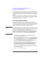
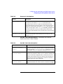
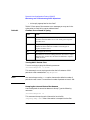
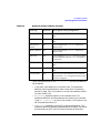
Default Configuration
If the /etc/nsswitch.conf file does not exist, or if the line for a
particular type of information is absent or syntactically incorrect, the
following default configuration is used:
passwd:
group:
hosts:
networks:
protocols:
rpc:
publickey:
netgroup:
automount:
aliases:
services:
files nis
files nis
dns [NOTFOUND=return]
nis [NOTFOUND=return]
nis [NOTFOUND=return]
nis [NOTFOUND=return]
nis [NOTFOUND=return]
nis [NOTFOUND=return]
files nis
files nis
nis [NOTFOUND=return]
nis [NOTFOUND=return] files
files
files
files
files
files
files
If your /etc/nsswitch.conf file contains a syntactically correct line for
a particular type of information, that line is used instead of the default.
For more information about configuring the Name Service Switch,
including the syntax of the configuration file and customizing your
configuration, see Installing and Administering NFS Services.
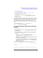
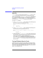
Troubleshooting the Name Service Switch
Issue the nsquery command to perform a hosts, passwd, or group
lookup, as follows:
/usr/contrib/bin/nsquery lookup_type lookup_query
The lookup_type can be hosts, passwd, or group.
The lookup_query can be a host name or IP address, a user name or
user ID, or a group name or group ID.
The nsquery command displays the Name Service Switch configuration
that is currently in use. Then, it displays the results of the query. The
following example uses nsquery to perform a lookup of the host name
romney:
# /usr/contrib/bin/nsquery hosts romney
Using "nisplus [NOTFOUND=return] files" for the hosts policy.
Searching nisplus for romney
romney was NOTFOUND
32
Chapter 2
Installing and Configuring Internet Services
Configuring the Name Service Switch
Switch configuration: Terminates Search
As an optional third argument to nsquery, you can supply a Name
Service Switch configuration in double quotes, as in the following
example:
# /usr/contrib/bin/nsquery passwd 30 "files nis"
Using "files nis" for the passwd policy.
Searching /etc/passwd for 30
User name: www
User ID: 30
Group ID: 1
Gecos:
Home Directory: /
Shell:
Switch configuration: Terminates Search
For more information, type man 1 nsquery at the HP-UX prompt.
Chapter 2
33
Installing and Configuring Internet Services
Configuring Internet Addresses
Configuring Internet Addresses
This section tells you how to configure your host to find other hosts on
the network, by host name or IP address. It contains the following
sections:
• “To Choose a Name Service” on page 34
• “To Edit the /etc/hosts File” on page 35
• “To Configure Routes” on page 36
• “To Change a Host’s IP Address” on page 37
To Choose a Name Service
HP-UX provides four ways of translating host names to IP addresses or
IP addresses to host names:
• The /etc/hosts file, a simple ASCII file that is searched
sequentially.
• BIND (Berkeley Internet Name Domain), which is Berkeley’s
implementation of the Domain Name System (DNS).
• NIS (Network Information Service), one of the NFS Services. (NIS
used to be called “Yellow Pages”.)
• NIS+ (the next generation of NIS). NIS+ is more scalable and has
better security features than NIS.
By configuring the Name Service Switch, you can use these name
services in any order you choose. See “Configuring the Name Service
Switch” on page 30.
If you have a large network, or you need to connect to Internet hosts
outside your local network, use BIND as your primary name service.
When you use BIND, you administer a central database containing only
the hosts on your local network, and you have access to the databases on
all the other hosts on the Internet. See “Configuring and Administering
the BIND Name Service” on page 71 for instructions on configuring
BIND.
If you have a large network and little need for Internet connectivity, you
can use NIS as your primary name service. The NIS hosts database is
34
Chapter 2
Installing and Configuring Internet Services
Configuring Internet Addresses
administered centrally on one of your hosts, but it must contain the
names and IP addresses of all the other hosts in your network. For
information on NIS, see Installing and Administering NFS Services.
If you have a small network and little need for Internet connectivity, you
can use the /etc/hosts file as your primary name service. Each host in
your network needs a copy of the /etc/hosts file containing the names
and addresses of all the other hosts in your network. For information on
the /etc/hosts file, see “To Edit the /etc/hosts File” on page 35.
If you choose to use BIND, NIS, or NIS+ as your primary name service,
you still need to configure a minimal /etc/hosts file so that your host
can boot if BIND, NIS, or NIS+ is not available.
To Edit the /etc/hosts File
You can use any text editor to edit the /etc/hosts file, or you can use
SAM. SAM (System Administration Manager) is Hewlett-Packard’s
windows-based user interface for performing system administration
tasks. To run SAM, type sam at the HP-UX prompt. SAM has an
extensive online help facility.
1. If no /etc/hosts file exists on your host, copy
/usr/newconfig/etc/hosts to /etc/hosts, or use ftp to copy the
/etc/hosts file to your host from another host on your network. Type
man 1 ftp for more information.
2. Make sure your /etc/hosts file contains the following line:
127.0.0.1
localhost
loopback
3. Add your own host’s IP address, name, and aliases to the /etc/hosts
file, as in the following example:
15.13.131.213
hpindlpk
romney
The first field is the IP address, the second is the official host name
(as returned by the hostname command), and any remaining fields
are aliases. Type man 4 hosts for more information.
4. If your host has more than one network interface installed, add a line
to /etc/hosts for each interface. The /etc/hosts entries for your
host will have the same official host name but different aliases and
different IP addresses.
5. Add any other hosts to the /etc/hosts file that you need to reach. If
you will use a BIND, NIS, or NIS+ server on a different host, add that
Chapter 2
35
Installing and Configuring Internet Services
Configuring Internet Addresses
host to your /etc/hosts file.
If you have no default gateway configured, and you add a host that is
not on your subnet, SAM will prompt you for the gateway. To stop the
prompting, configure a default gateway.
6. If you are not using SAM, you must configure a gateway for each host
that is not on your subnet. See “To Configure Routes” on page 36.
7. Make sure the /etc/hosts file is owned by user root and group
other, and make sure the permissions are set to 0444 (-r--r--r--).
To Configure Routes
1. If you use only one gateway to reach all systems on other parts of the
network, configure a default gateway.
You can use SAM to configure a default gateway, or if you are not
using SAM, issue the following command:
/usr/sbin/route add default gateway_address 1
where gateway_address is the IP address of the gateway host.
Then, set the following environment variables in the
/etc/rc.config.d/netconf file:
ROUTE_DESTINATION[0]="default"
ROUTE_GATEWAY[0]="gateway_address"
ROUTE_COUNT[0]="1"
If the default gateway is your own host, set the ROUTE_COUNT variable
to 0. Otherwise, set it to 1.
2. If your host is a gateway, configure the destination networks that can
be reached from its network interfaces. Issue the following command
for each network interface on your host:
/usr/sbin/route add net destination IP_address
where destination is a network address reachable by your host, and
IP_address is the address of the network interface.
Then, create a new set of routing variables in the
/etc/rc.config.d/netconf file for each network interface.
Whenever you create a new set of variables, increment the number in
square brackets, as in the following example:
ROUTE_DESTINATION[1]="15.13.131.0"
36
Chapter 2
Installing and Configuring Internet Services
Configuring Internet Addresses
ROUTE_GATEWAY[1]="15.13.131.213"
ROUTE_COUNT[1]="0"
3. If you will not be using gated, configure routes to all the networks
you need to reach. Type the following command for each network you
need to reach from your host:
/usr/sbin/route add net network_address gateway_address
Then, create a new set of routing variables in the
/etc/rc.config.d/netconf file for each new route. Whenever you
create a new set of variables, increment the number in square
brackets.
ROUTE_DESTINATION[n]="network_address"
ROUTE_GATEWAY[n]="gateway_address"
ROUTE_COUNT[n]="1"
If ROUTE_GATEWAY[n] is your own host, set ROUTE_COUNT[n] to 0.
Otherwise, set it to 1.
4. Type the following command to verify the routes you have configured:
/usr/bin/netstat -r
For more information on static routing, type man 1M route or man 7
routing at the HP-UX prompt.
If you have a large and complicated network, use gated for dynamic
routing. See “Configuring gated” on page 319 for more information.
To Change a Host’s IP Address
When you use SAM to change a host’s IP address, SAM does not perform
all these steps. For example, SAM does not update BIND or NIS
databases.
1. Change the host’s IP address in the /etc/hosts file. See “To Edit the
/etc/hosts File” on page 35.
2. Change the IP_ADDRESS[n] variable in the
/etc/rc.config.d/netconf file to the new IP address.
3. If the host is on a network that uses BIND, change the host’s IP
address in the data files of the authoritative name servers. See
“Configuring and Administering the BIND Name Service” on page
71.
If the host is on a network that uses NIS, change its IP address in the
Chapter 2
37
Installing and Configuring Internet Services
Configuring Internet Addresses
/etc/hosts file on the NIS master server, and issue the following
commands to regenerate the hosts database and push it out to the
NIS slave servers:
cd var/yp
/usr/ccs/bin/make hosts
If the host is on a network that uses NIS+, use the nistbladm (1)
command to change the host’s IP address in the NIS+ hosts table.
4. If the host is moving to a different subnet, change the
ROUTE_DESTINATION, ROUTE_GATEWAY, and BROADCAST_ADDRESS[n]
variables in /etc/rc.config.d/netconf.
If the host is moving to a network that uses a different subnet mask,
change the SUBNET_MASK[n] variable in
/etc/rc.config.d/netconf.
5. If the host is moving to a different network, you may have to
configure new routes for it. See “To Configure Routes” on page 36.
6. If the host is on a network that uses gated, change its IP address on
all the gated routers. See “Configuring gated” on page 319.
7. If the host is a BOOTP client, change its IP address in the
/etc/bootptab file on the BOOTP server. If the host is a BOOTP
server, and a BOOTP relay agent is configured to relay boot requests
to the host, change the host’s IP address in the /etc/bootptab file on
the BOOTP relay agent. See “Configuring TFTP and BOOTP Servers”
on page 217.
8. If the host is an NTP server, change its IP address in the
/etc/ntp.conf file on NTP clients. If the host is an NTP client and is
moving to another network, you might have to configure a different
NTP server in its /etc/ntp.conf file. See “Configuring the Network
Time Protocol (NTP)” on page 281.
9. Reboot the host.
38
Chapter 2
Installing and Configuring Internet Services
Configuring the Internet Daemon, inetd
Configuring the Internet Daemon, inetd
The internet daemon, /usr/sbin/inetd, is the master server for many
of the Internet Services. The inetd daemon listens for connection
requests for the services listed in its configuration file and starts up the
appropriate server when it receives a request.
The inetd daemon is always started as part of the boot process, by the
startup script /sbin/init.d/inetd.
The /etc/inetd.conf file is the inetd configuration file, which lists the
services that may be started by inetd. In addition to the configuration
file, you can configure an optional security file called
/var/adm/inetd.sec, which restricts access to the services started by
inetd.
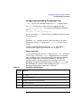
This section gives instructions for completing the following tasks:
• “To Edit the /etc/inetd.conf File” on page 39
• “To Edit the /var/adm/inetd.sec File” on page 40
If you want to write your own service and tie it in to inetd, see the
Berkeley IPC Programmer's Guide.
To Edit the /etc/inetd.conf File
1. Make sure the following lines exist in /etc/inetd.conf. If any of the
lines starts with a pound sign (#), remove the pound sign to enable
the service.
ftp
telnet
tftp
bootps
finger
login
shell
exec
stream
stream
dgram
dgram
stream
stream
stream
stream
tcp
tcp
udp
udp
tcp
tcp
tcp
tcp
nowait
nowait
wait
wait
nowait
nowait
nowait
nowait
root
root
root
root
bin
root
root
root
/usr/lbin/ftpd
/usr/lbin/telnetd
/usr/lbin/tftpd
/usr/lbin/bootpd
/usr/lbin/fingerd
/usr/lbin/rlogind
/usr/lbin/remshd
/usr/lbin/rexecd
ftpd -l
telnetd
tftpd
bootpd
fingerd
rlogind
remshd
rexecd
To disable any of these services, comment out the line by typing a
pound sign (#) as the first character on the line.
2. If you made any changes to /etc/inetd.conf, type the following
command to force inetd to read its configuration file:
Chapter 2
39
Installing and Configuring Internet Services
Configuring the Internet Daemon, inetd
/usr/sbin/inetd -c
3. Make sure /etc/inetd.conf is owned by user root and group other,
and make sure its permissions are set to 0444 (-r--r--r--).
For more information, type man 4 inetd.conf or man 1M inetd.
To Edit the /var/adm/inetd.sec File
The /var/adm/inetd.sec file is a security file that inetd reads to
determine which remote hosts are allowed access to the services on your
host. The inetd.sec file is optional; you do not need it to run the
Internet Services.
You can use either a text editor or SAM to edit the inetd.sec file. SAM
(System Administration Manager) is Hewlett-Packard’s windows-based
user interface for performing system administration tasks. To run SAM,
type sam at the HP-UX prompt. SAM has an extensive online help
facility.
1. If the /var/adm/inetd.sec file does not exist on your host, copy
/usr/newconfig/var/adm/inetd.sec to /var/adm/inetd.sec.
2. Create one line in inetd.sec for each service to which you want to
restrict access. Do not create more than one line for any service.
Each line in the /var/adm/inetd.sec file has the following syntax:
service_name {allow} host_specifier [host_specifier...]
{deny}
where service_name is the first field in an entry in the
/etc/inetd.conf file, and host_specifier is a host name, IP
address, IP address range, or the wildcard character (*).
3. Make sure the /var/adm/inetd.sec file is owned by user root and
group other, and make sure its permissions are set to 0444
(-r--r--r--).
Following are some example lines from an inetd.sec file:
login allow 10.*
shell deny vandal hun
tftp deny *
The first example allows access to rlogin from any IP address beginning
with 10. The second example denies access to remsh and rcp from hosts
vandal and hun. The third example denies everyone access to tftp.
40
Chapter 2
Installing and Configuring Internet Services
Configuring the Internet Daemon, inetd
Only the services configured in /etc/inetd.conf can be configured in
/var/adm/inetd.sec.
For more information, type man 4 inetd.sec or man 1M inetd.
Chapter 2
41
Installing and Configuring Internet Services
Configuring Logging for the Internet Services
Configuring Logging for the Internet Services
This section tells you how to complete the following tasks:
• “To Configure syslogd” on page 42
• “To Maintain System Log Files” on page 43
• “To Configure inetd Connection Logging” on page 43
• “To Configure ftpd Session Logging” on page 44
To Configure syslogd
The Internet daemons and servers log informational and error messages
through syslog. You can monitor these messages by running syslogd.
You can determine the type and extent of monitoring through syslogd’s
configuration file, /etc/syslog.conf.
Each line in /etc/syslog.conf has a “selector” and an “action”. The
selector tells which part of the system generated the message and what
priority the message has. The action specifies where the message should
be sent.
The part of the selector that tells where a message comes from is called
the “facility”. All Internet daemons and servers, except sendmail, log
messages to the daemon facility. sendmail logs messages to the mail
facility. syslogd logs messages to the syslog facility. You may indicate
all facilities in the configuration file with an asterisk (*).
The part of the selector that tells what priority a message has is called
the “level”. Selector levels are debug, information, notice, warning,
error, alert, emergency, and critical. A message must be at or above
the level you specify in order to be logged.
The “action” allows you to specify where messages should be directed.
You can have the messages directed to files, users, the console, or to a
syslogd running on another host.
The following is the default configuration for /etc/syslog.conf:
mail.debug
*.info,mail.none
*.alert *.alert
*.emerg
42
/var/adm/syslog/mail.log
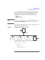
/var/adm/syslog/syslog.log
/det/console root
*
Chapter 2
Installing and Configuring Internet Services
Configuring Logging for the Internet Services
With this configuration, all mail log messages at the debug level or
higher are sent to /var/adm/syslog/mail.log. Log messages from any
facility at the information level or higher (but no mail messages) are
sent to /var/adm/syslog/syslog.log. Log messages from any facility
at the alert level or higher are sent to the console and any terminal
where the superuser is logged in. All messages at the emergency level or
higher are sent to all users on the system.
For more information about syslogd and its configuration file, type man
3C syslog or man 1M syslogd at the HP-UX prompt.
To Maintain System Log Files
The log files specified in your syslogd configuration can fill up your disk
if you do not monitor their size. To control the size of these files, do the
following:
1. Remove or rename your log files as in the following example:
cd /var/adm/syslog
mv mail.log mail.log.old
mv syslog.log sylog.log.old
2. Restart syslogd with the following commands:
cd /sbin/init.d
syslogd stop
syslogd start
When you reboot your system, each log file is moved to filename.old
automatically, and new log files are started.
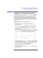
To Configure inetd Connection Logging
The inetd daemon can log connection requests through syslogd. It logs
successful connections at the information level and unsuccessful
connection attempts at the notice level. By default, inetd starts up
with connection logging turned off.
If inetd is running with connection logging turned off, issue the
following command to start it:
/usr/sbin/inetd -l
If inetd is running with connection logging turned on, the same
command turns it off. For more information, type man 1M inetd.
Chapter 2
43
Installing and Configuring Internet Services
Configuring Logging for the Internet Services
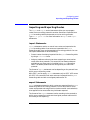
To Configure ftpd Session Logging
To configure ftpd to log messages about an ftp session, including
commands, logins, login failures, and anonymous ftp activity, follow
these steps:
1. Add the -L option to the ftp line in the /etc/inetd.conf file, as in
the following example:
ftp stream tcp nowait root /usr/lbin/ftpd ftpd -L
2. Issue the following command to force inetd to read its configuration
file:
/usr/sbin/inetd -c
For more information, type man 1M ftpd at the HP-UX prompt. Included
in this man page is a complete list of error messages.
For more information on logging ftp file transfer information, see
“Configuring Logging for ftp” on page 51.
44
Chapter 2
Installing and Configuring Internet Services
Configuring ftp
Configuring ftp
Beginning with HP-UX 11.0, ftp provides support for Pluggable
Authentication Module (PAM). PAM is an Open Group standard (RFC
86.0) for user authentication, password modification, and validation of
accounts.
The PAM configuration file (/etc/pam.conf) has been updated to
include ftp. The default authentication mechanism is UNIX, and its
entry in pam.conf is as follows:
ftp
ftp
auth required /usr/lib/security/libpam_unix.1
account required
/usr/lib/security/libpam_unix.1
DCE is the other supported authentication mechanism. To change the
default to be DCE, edit the entry in pam.conf to read as follows:
ftp
ftp
auth required /usr/lib/security/libpam_dce.1
account required
/usr/lib/security/libpam_dce.1
For more information, see the manual Managing Systems and
Workgroups.
Chapter 2
45
Installing and Configuring Internet Services
Configuring Anonymous ftp Access
Configuring Anonymous ftp Access
Anonymous ftp allows a user without a login on your host to transfer
files to and from a public directory. A user types the ftp command to
connect to your host and types anonymous or ftp as a login name. The
user can type any string of characters as a password. (By convention, the
password is the host name of the user’s host). The anonymous user is
then given access only to user ftp’s home directory, usually called
/home/ftp.
Configuring anonymous ftp access involves the following tasks,
described in this section:
• “To Add User ftp to /etc/passwd” on page 46
• “To Create the Anonymous ftp Directory” on page 46
You can follow the instructions in this section, or you can use SAM to
configure anonymous ftp access. SAM (System Administration
Manager) is the Hewlett-Packard windows-based user interface for
performing system administration tasks. To run SAM, type sam at the
HP-UX prompt. SAM has an extensive online help facility.
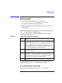
To Add User ftp to /etc/passwd
Use a text editor to add a line for user ftp to the /etc/passwd file, as in
the following example:
ftp:*:500:guest:anonymous ftp:/home/ftp:/usr/bin/false
The password field should be *, the group membership should be guest,
and the login shell should be /usr/bin/false. In this example, user
ftp’s user ID is 500, and the anonymous ftp directory is /home/ftp.
Type man 4 passwd at the HP-UX prompt for information on the passwd
file.
To Create the Anonymous ftp Directory
1. Create the ftp home directory that you configured in the
/etc/passwd file, as in the following example:
cd /home
mkdir ftp
46
Chapter 2
Installing and Configuring Internet Services
Configuring Anonymous ftp Access
2. Create the subdirectory /usr/bin under the ftp home directory:
cd /home/ftp
mkdir usr
cd usr
mkdir bin
3. Copy the ls and pwd commands from /sbin to ˜ftp/usr/bin, and set
the permissions on the commands to 0111 (executable only):
cp /sbin/ls /home/ftp/usr/bin
cp /sbin/pwd /home/ftp/usr/bin
chmod 0111 /home/ftp/usr/bin/ls
chmod 0111 /home/ftp/usr/bin/pwd
4. Set the owner of the ˜ftp/usr/bin and ˜ftp/usr directories to root,
and set the permissions to 0555 (not writeable):
chown
chmod
chown
chmod
root
0555
root
0555
/home/ftp/usr/bin
/home/ftp/usr/bin
/home/ftp/usr
/home/ftp/usr
5. Create the subdirectory etc under the ftp home directory:
cd /home/ftp
mkdir etc
6. Copy /etc/passwd and /etc/group to ˜ftp/etc. These files are
required by the ls command, to display the owners of files and
directories under ˜ftp.
cp /etc/passwd /home/ftp/etc
cp /etc/group /home/ftp/etc
7. Replace the password field in all entries in /home/ftp/etc/passwd
with *, and delete the shell field from the end of each entry:
ftp:*:500:guest:anonymous ftp:/home/ftp:
acb:*:8996:20::/home/acb:
8. Replace the password field in all entries in /home/ftp/etc/group
with *:
users:*:20:acb
guest:*:21:ftp
9. Set the owner of the files in ˜ftp/etc to root, and set the
permissions to 0444 (read only):
chown root /home/ftp/etc/passwd
chmod 0444 /home/ftp/etc/passwd
Chapter 2
47
Installing and Configuring Internet Services
Configuring Anonymous ftp Access
chown root /home/ftp/etc/group
chmod 0444 /home/ftp/etc/group
10. Set the owner of ˜ftp/etc to root, and set the permissions to 0555
(not writeable):
chown root /home/ftp/etc
chmod 0555 /home/ftp/etc
11. Create a directory called pub under ˜ftp. Set its owner to user ftp
and its permissions to 0777 (writeable by all). Anonymous ftp users
can put files in this directory to make them available to other
anonymous ftp users.
mkdir /home/ftp/pub
chown ftp /home/ftp/pub
chmod 0777 /home/ftp/pub
12. Create a directory called dist under ˜ftp. Set its owner to user root
and its permissions to 0755 (writeable only by root). The superuser
can put read-only files in this directory to make them available to
anonymous ftp users.
mkdir /home/ftp/dist
chown root /home/ftp/dist
chmod 0755 /home/ftp/dist
13. Set the owner of user ftp’s home directory to root and the
permissions to 0555 (not writeable).
chown root /home/ftp
chmod 0555 /home/ftp
An anonymous ftp directory has the structure shown in Figure 2-1:
48
Chapter 2
Installing and Configuring Internet Services
Configuring Anonymous ftp Access
Figure 2-1
Directory Structure for Anonymous ftp Account
/
usr
home
etc
bin
usr
...
passwd file
ftp
ftp
etc
pub
dist
passwd
<user file>
<user file>
group
<user file>
<user file>
<user file>
<user file>
ls
...
pwd
Chapter 2
...
bin
49
Installing and Configuring Internet Services
Configuring ftp with /etc/ftpd/ftpaccess
Configuring ftp with /etc/ftpd/ftpaccess
The /etc/ftpd/ftpaccess configuration file is the primary
configuration file for defining how the ftpd daemon operates. The
/etc/ftpd/ftpaccess file allows you to configure a wide variety of ftp
features, such as the number of ftp login tries permitted, ftp banner
displays, logging of incoming and outgoing file transfers, access
permissions, use of regular expressions, etc. (For complete details on this
file, see the ftpaccess (4) manpage.)
Enabling/Disabling the ftpaccess File
• To enable the /etc/ftpd/ftpaccess file, specify the -a option for the
ftp entry in the /etc/inetd.conf file. For example,
ftp stream tcp nowait root /usr/lbin/ftpd ftpd -a -l -d
• To disable the /etc/ftpd/ftpaccess file, specify the -A option for the ftp
entry in the /etc/inetd.conf file. For example,
ftp stream tcp nowait root /usr/lbin/ftpd ftpd -A -l -d
50
Chapter 2
Installing and Configuring Internet Services
Configuring Logging for ftp
Configuring Logging for ftp
You can log both ftp session information and file transfer information, as
explained in the following sections.
Logging ftp Sessions
You can specify ftp session logging using the log commands keyword in
the /etc/ftpd/ftpaccess file.
log commands Enables or disables logging of an ftp session to syslog,
including commands, logins, login failures, and
anonymous ftp activity.
(This entry overrides the -L option specified for the ftp
entry in/etc/inetd.conf.)
For details on the preceding keyword, see the ftpaccess(4) manpage.
NOTE
To enable the /etc/ftpd/ftpaccess file you must specify the -a option
in the ftp entry of the /etc/inetd.conf file.
Logging ftp File Transfers
You can log file transfer information from the ftp server daemon to the
/var/adm/syslog/xferlog log file. The xferlog file records file transfer
information such as current time, file transfer time, remote host,
filename, file size, whether the file transfer was in ascii or binary format,
etc. For details on all types of information recorded in the xferlog file,
see the xferlog(5) manpage.
You can enable file transfer logging either by editing the
/etc/ftpd/ftpaccess file or by editing the /etc/inetd.conf file. Each
of these methods is described following.
Chapter 2
51
Installing and Configuring Internet Services
Configuring Logging for ftp
Configuring Logging in the /etc/ftpd/ftpaccess File
To log incoming and outgoing ftp file transfers, edit the
/etc/ftpd/ftpaccess file using the log transfers keyword.
log transfers Enables or disables logging of file transfers for real or
anonymous ftp users to /var/adm/syslog/xferlog.
Logging of transfers to the server (incoming) can be
enabled separately from transfers from the server
(outbound).
For details on the preceding keyword, see the ftpaccess(4) manpage.
NOTE
To enable the /etc/ftpd/ftpaccess file, you must specify the -a option
in the ftp entry of the /etc/inetd.conf file.
Configuring Logging in the /etc/inetd.conf File
To log incoming and outgoing ftp file transfers, edit the /etc/inetd.conf
file using the -i and -o options with the ftp entry.
-i
This option logs all the incoming files received by the
ftp server to the /var/adm/syslog/xferlog log file.
This option is overridden by the log transfers entry
in the /etc/ftpd/ftpaccess file.
-o
This option logs all outgoing files transmitted by ftpd to
/var/adm/syslog/xferlog. This option is overridden
by the log transfers entry in the
/etc/ftpd/ftpaccess file.
Example of Configuring Logging in /etc/inetd.conf
In the following example, the /etc/inetd.conf entry logs both incoming
and outgoing ftp file transfers.
ftp
52
stream tcp nowait root /usr/lbin/ftpd ftpd -a -l -d -i -o
Chapter 2
Installing and Configuring Internet Services
Installing sendmail
Installing sendmail
When you install sendmail, the installation script creates and modifies
files on the system that are needed for sendmail operation. The
sendmail configuration file supplied with HP-UX 11.0 will work without
modifications for most installations. Therefore, the only steps you must
do are: set up sendmail servers to run with NFS, configure and start
sendmail clients, and verify that sendmail is running properly.
This section contains information about the following tasks:
• “Installing sendmail on a Standalone System” on page 53
• “Installing sendmail on a Mail Server” on page 54
• “Installing sendmail on a Mail Client” on page 55
• “Verifying Your sendmail Installation” on page 57
NOTE
HP recommends that you use sendmail with the BIND name server. The
BIND name server should have an MX record for every host in the
domain(s) that it serves. For more information on how sendmail uses MX
records, see “Installing and Administering sendmail” on page 153.
Installing sendmail on a Standalone System
When sendmail is installed, it is automatically configured to send and
receive mail for users on the local system only. The standalone system
processes all outbound mail and establishes connections to the message
destination host or to Mail Exchanger (MX) hosts (see “Installing and
Administering sendmail” on page 153 for more information). The
sendmail daemon is then started when you reboot the system, so you do
not need to make any changes to any system files.
The sendmail installation script makes the following configuration
changes:
• Sets the SENDMAIL_SERVER variable in the
/etc/rc.config.d/mailservs file to 1. This ensures that the
sendmail daemon is started whenever you reboot your system or run
the sendmail startup script.
Chapter 2
53
Installing and Configuring Internet Services
Installing sendmail
• Creates /etc/mail/sendmail.cf and /etc/mail/aliases files with
default configurations. These files are created with root as the owner,
other as the group, and permissions set to 0444.
NOTE
If an /etc/mail/sendmail.cf file already exists, the existing file is
saved to /etc/mail/#sendmail. If an /etc/mail/aliases file already
exists, then the sendmail installation script does not create it.
• Creates the file /etc/mail/sendmail.cw that contains the hostname
and the fully-qualified hostname for the system. For example, the
system dog in the domain cup.hp.com has the following entries in
the file:
dog
dog.cup.hp.com
• Finally, the installation script issues the following command to run
the sendmail startup script:
/sbin/init.d/sendmail start
The sendmail startup script generates the aliases database from the
/etc/mail/aliases source file. The generated database is located in
the file /etc/mail/aliases.db.
The sendmail startup script then starts the sendmail daemon by
issuing the following command:
/usr/sbin/sendmail
-bd
-q30m
The -q30m option tells sendmail to process the mail queue every 30
minutes.
For more information about sendmail command line options, type
man 1M sendmail at the HP-UX prompt.
Installing sendmail on a Mail Server
This section describes how to configure a system to allow users on other
(client) systems to use sendmail. The mail server receives mail for local
users and for the users on client systems. Users on client systems then
NFS mount the mail directory from the server and read mail over an
NFS link. For more information on how sendmail clients and servers
work, see “Default Client-Server Operation” on page 178.
54
Chapter 2
Installing and Configuring Internet Services
Installing sendmail
The sendmail installation script performs the configuration changes
that are described in “Installing sendmail on a Standalone System” on
page 53. To set the system up as an NFS server and allow the sendmail
clients to read and write to the /var/mail directory, do the following:
1. Make sure all mail users have accounts on the mail server and that
their user IDs and group IDs on the mail server are the same as on
the client machines. (This step is not necessary if you are using NIS
or NIS+ and your mail server is in the same NIS or NIS+ domain as
the clients.)
2. In the /etc/rc.config.d/nfsconf file, use a text editor to set the
NFS_SERVER variable to 1.
3. Use a text editor to add the following line to the /etc/exports file:
/var/mail
-access=client,client...
where each mail client is listed in the access list. If the /etc/exports
file does not exist, you will have to create it.
4. Issue the following command to run the NFS startup script:
/sbin/init.d/nfs.server
start
For more information on NFS, see Installing and Administering NFS
Services.
Installing sendmail on a Mail Client
sendmail clients do not receive mail on their local system; instead, users
on the client systems obtain their mail on the mail server. User mail
directories reside on the server, and users read their mail over an NFS
link. By default, a sendmail client forwards to the server any local mail
(a user address destined for the client system) and sends non-local mail
directly to the destination system or MX host. Outgoing mail appears to
originate from the server, so replies are sent to the server. For more
information on how sendmail clients and servers work, see “Installing
and Administering sendmail” on page 153. sendmail clients can be
diskless systems.
To configure a sendmail client system to access a sendmail server:
1. In the /etc/rc.config.d/mailservs file, use a text editor to set the
SENDMAIL_SERVER variable to 0. This ensures that the sendmail
daemon will not be started when you reboot your system or run the
sendmail startup script.
Chapter 2
55
Installing and Configuring Internet Services
Installing sendmail
2. In the /etc/rc.config.d/mailservs file, use a text editor to set the
SENDMAIL_SERVER_NAME variable to the host name or IP address of
the mail server you will use (the machine that will run the sendmail
daemon).
3. In the /etc/rc.config.d/nfsconf file, use a text editor to set the
NFS_CLIENT variable to 1.
4. Use a text editor to add the following line to the /etc/fstab file:
servername:/var/mail
/var/mail
nfs
0
0
where servername is the name configured in the
SENDMAIL_SERVER_NAME variable in /etc/rc.config.d/mailservs.
If the /etc/fstab file does not exist, you will have to create it.
5. Issue the following command to run the sendmail startup script:
/sbin/init.d/sendmail start
6. Issue the following command to run the NFS startup script:
/sbin/init.d/nfs.client start
The sendmail startup script assumes that this system will use the host
specified by the SENDMAIL_SERVER_NAME variable as the mail hub. The
script also assumes that mail sent from this system should appear to be
from the host specified by the SENDMAIL_SERVER_NAME variable (this
feature may previously have been known as “site hiding”). The script
therefore modifies the macros DM (for “masquerade”) and DH (for “mail
hub”) in the system’s /etc/mail/sendmail.cf file to use the host
specified by the SENDMAIL_SERVER_NAME variable. Note that if the DM and
DH macros have previously been defined, the startup script does not
modify them.
As mentioned earlier, the client system now forwards local mail to the
mail server and forwards other mail directly to remote systems. To
configure the client system to relay all mail to the mail server for
delivery, see “Modifying the Default sendmail Configuration File” on
page 185.
The NFS startup script NFS-mounts the /var/mail directory from the
mail server to your system. For more information on NFS, see Installing
and Administering NFS Services.
56
Chapter 2
Installing and Configuring Internet Services
Installing sendmail
Verifying Your sendmail Installation
You can verify that sendmail has been installed properly and is working
properly by doing the things described in the following sections:
• “Mailing to a Local User” on page 57
• “Mailing to a Remote User with UUCP Addressing” on page 57 (if
you are using it).
• “Mailing to a Remote User with the SMTP Transport” on page 58 (if
you are using it).
Mailing to a Local User
To check your local mailer or user agent, mail a message to a local user
(for example, joe) on your system:
date
|
mailx
-s
"Local sendmail Test"
joe
This should result in a message similar to the following being sent to
user joe:
From joe Wed Aug 6 09:18 MDT 1986
Received: by node2; Wed, 6 Aug 86 09:18:53 mdt
Date: Wed, 6 Aug 86 09:18:53 mdt
From: Joe User <joe>
Return-Path: <joe>
To: joe
Subject: Local sendmail Test
Wed Aug 6 09:18:49 MDT 1986
An entry in your /var/adm/syslog/mail.log file should have been
logged for the local message transaction. See “Configuring and Reading
the sendmail Log” on page 64 for more information.
Mailing to a Remote User with UUCP Addressing
For this test, mail a message to a remote user with the UUCP transport
by using a host!user address, where host is a system to which your
local host has a direct UUCP connection. (The uuname command lists the
UUCP names of known systems. Type man 1 uuname at the HP-UX
prompt for more information.)
To verify both inbound and outbound UUCP connections, mail the
message in a loop, using the syntax remote_host!my_host!user. For
example, if you try
Chapter 2
57
Installing and Configuring Internet Services
Installing sendmail
date | mailx -s "UUCP Test" node1!node2!joe
and node2 is your local host, you should receive a message similar to
this:
From node1!node2!joe Wed Aug 6 09:48 MDT 1986
Received: by node2; Wed, 6 Aug 86 09:48:09 mdt
Return-Path: <node1!node2!joe>
Received: from node1.UUCP; Wed, 6 Aug 86 09:30:16
Received: by node1; Wed, 6 Aug 86 09:30:16 mdt
Received: from node2.UUCP; Wed, 6 Aug 86 09:26:18
Received: by node2; Wed, 6 Aug 86 09:26:18 mdt
Date: Wed, 6 Aug 86 09:26:18 mdt
From: Joe User <node1!node2!joe>
To: node1!node2!joe
Subject: UUCP Test
Wed Aug
6 09:26:15 MDT 1986
An entry in your /var/adm/syslog/mail.log file should have been
logged for the UUCP mail transaction. See “Configuring and Reading
the sendmail Log” on page 64 for more information.
NOTE
In this example, if you mail to yourself, and if the local system is running
sendmail, be sure the configuration file on the local system has set the m
option (for a pre-version 6 configuration file) or the MeToo option (for a
version 6 configuration file). The local system’s configuration file should
contain a line beginning with Om or O MeToo. If such a line is not in the
local host’s configuration file, sendmail on the local host notices that the
sender is the same as the recipient and your address is removed from the
recipient list.
Mailing to a Remote User with the SMTP Transport
For this test, mail a message to a remote user with the SMTP transport
using a user@host address, where host is a system that provides an
SMTP server (for example, the sendmail daemon).
To verify both inbound and outbound SMTP connections, mail the
message in a loop, using the syntax user%my_host@remote_host. For
example, if you try
date | mailx -s "Round Robin SMTP" joe%node2@node1
58
Chapter 2
Installing and Configuring Internet Services
Installing sendmail
you should receive a message similar to the following:
From joe@node2 Wed Aug 6 14:22 MDT 1986
Received: from node1 by node2; Wed, 6 Aug 86 14:22:56
Return-Path: <joe@node2>
Received: from node2 by node1; Wed, 6 Aug 86 14:25:04
Received: by node2; Wed, 6 Aug 86 14:22:31 mdt
Date: Wed, 6 Aug 86 14:22:31 mdt
From: Joe User <joe@node2>
To: joe%node2@node1
Subject: Round Robin SMTP
Wed Aug
mdt
mdt
6 14:22:28 MDT 1986
An entry in your /var/adm/syslog/mail.log file should have been
logged for the SMTP mail transaction. See “Configuring and Reading
the sendmail Log” on page 64 for more information.
NOTE
In this example, if you mail to yourself, and if the remote system is
running sendmail, be sure the configuration file on the remote system
has set the m option (for a pre-version 6 configuration file) or the MeToo
option (for a version 6 configuration file). The remote system’s
configuration file should contain a line beginning with Om or O MeToo. If
such a line is not in the remote host’s configuration file, sendmail on the
remote host notices that the sender is the same as the recipient and your
address is removed from the recipient list.
Chapter 2
59
Installing and Configuring Internet Services
Troubleshooting sendmail
Troubleshooting sendmail
This section describes the following techniques for troubleshooting
sendmail:
• “Keeping the Aliases Database Up to Date” on page 60
• “Verifying Address Resolution and Aliasing” on page 60
• “Verifying Message Delivery” on page 61
• “Contacting the sendmail Daemon to Verify Connectivity” on page 62
• “Setting Your Domain Name” on page 63
• “Attempting to Start Multiple sendmail Daemons” on page 63
• “Configuring and Reading the sendmail Log” on page 64
• “Printing and Reading the Mail Queue” on page 67
Almost all sendmail troubleshooting must be done as superuser.
Keeping the Aliases Database Up to Date
The aliases database must be rebuilt if changes have been made to the
aliases text file.
You must restart sendmail after you change the configuration file or the
aliases database.
Issue the following commands on a standalone system or on the mail
server to rebuild the aliases database and restart sendmail:
/sbin/init.d/sendmail stop
/sbin/init.d/sendmail start
Updating Your NIS or NIS+ Aliases Database
If you are using NIS or NIS+ to manage your aliases database, see
Installing and Administering NFS Services.
Verifying Address Resolution and Aliasing
In order to deliver a message, sendmail must first resolve the recipient
addresses appropriately. To determine how sendmail would route mail
60
Chapter 2
Installing and Configuring Internet Services
Troubleshooting sendmail
to a particular address, issue the following command:
/usr/sbin/sendmail
-bv
-v
-oL10
address [address...]
The -bv (verify mode) option causes sendmail to verify addresses
without collecting or sending a message.
The -v (verbose) flag causes sendmail to report alias expansion and
duplicate suppression.
The -oL10 (log level) option sets the log level to 10. At log level 10 and
above, sendmail -bv reports the mailer and host to which it resolves
recipient addresses.
For hosts that resolve to IPC mailers, MX hosts are not reported when
using verify mode, because MX records are not collected until delivery is
actually attempted.
If the address is not being resolved as you expect, you may have to
modify one or more of the following:
• The sendmail configuration file.
• The files or programs from which file classes are generated.
• The name server configuration.
• The UUCP configuration.
More detailed information about how the configuration file is rewriting
the recipient addresses is provided by address test mode:
/usr/sbin/sendmail
-bt
Verifying Message Delivery
You can observe sendmail’s interaction with the delivery agents by
delivering the message in verbose mode, as in the following example:
/usr/sbin/sendmail -v
[email protected]
sendmail responds with the following information:
[email protected]... aliased to [email protected]
sendmail is now ready for you to type a message. After the message,
type a period (.) on a line by itself, as in the following example:
This is only a test.
.
Chapter 2
61
Installing and Configuring Internet Services
Troubleshooting sendmail
sendmail responds with the following information:
[email protected]... Connecting to local host (local)...
[email protected]... Executing "/bin/rmail -d myname"
[email protected]... Sent
sendmail has interfaces to three types of delivery agents. In verbose
mode, sendmail reports its interactions with them as follows:
• Mailers that use SMTP to a remote host over a TCP/IP connection
(IPC mailers):
In verbose mode, sendmail reports the name of the mailer used, each
MX host (if any) to which it tries to connect, and each internet address
it tries for each host. Once a connection succeeds, the SMTP
transaction is reported in detail.
• Mailers that run SMTP (locally) over pipes:
The name of the mailer used and the command line passed to exec()
are reported. Then the SMTP transaction is reported in detail. If the
mailer returns an abnormal error status, that is also reported.
• Mailers that expect envelope information from the sendmail
command line and expect message headers and message body from
standard input:
The name of the mailer used and the command line passed to exec()
are reported. If the mailer returns an abnormal error status, that is
also reported.
Contacting the sendmail Daemon to Verify
Connectivity
It is possible to talk to the sendmail daemon and other SMTP servers
directly with the following command:
telnet
host
25
This can be used to determine whether an SMTP server is running on
host. If not, your connection attempt will return “Connection refused.”
Once you establish a connection to the sendmail daemon, you can use
the SMTP VRFY command to determine whether the server can route to a
particular address. For example,
telnet furschlugginer 25
220 furschlugginer.bftxp.edu SMTP server ready
62
Chapter 2
Installing and Configuring Internet Services
Troubleshooting sendmail
vrfy aen
250 Alfred E. Newman <[email protected]>
vrfy [email protected]
554 [email protected]: unable to route to domain morb.poot
quit
221 furschlugginer.bftxp.edu SMTP server shutting down
Not all SMTP servers support the VRFY and EXPN commands.
Setting Your Domain Name
If sendmail cannot resolve your domain name, you may see the following
warning message in your syslog file:
WARNING: local host name name is not qualified; fix $j in
config file
To resolve this problem, do one of the following:
• In the /etc/mail/sendmail.cf file, uncomment the following line by
deleting the pound sign (#) at the beginning of the line:
Dj$w.Foo.COM
Change “Foo.COM” to the name of your domain (for example,
“HP.COM”).
• Modify the /etc/hosts file, making sure that the fully-qualified
name of the system is listed first. For example, the entry in the file
should be “255.255.255.255 dog.cup.hp.com dog” and not
“255.255.255.255 dog dog.cup.hp.com.”
Attempting to Start Multiple sendmail Daemons
If you attempt to start sendmail when there is already a sendmail
daemon running, the following message may be logged to both the syslog
file and to the console:
NO QUEUE: SYSERR (root) opendaemonsocket: cannot bind:
Address already in use
This message means that a sendmail daemon is already running. You
can use either /sbin/init.d/sendmail stop or killsm to stop the
running daemon.
Chapter 2
63
Installing and Configuring Internet Services
Troubleshooting sendmail
Configuring and Reading the sendmail Log
sendmail logs its mail messages through the syslogd logging facility.
The syslogd configuration should write mail logging to the file
/var/adm/syslog/mail.log. You can do this by adding the following
line in /etc/syslog.conf:
mail.debug
/var/adm/syslog/mail.log
You can use the HP mtail utility to look at a specified number of the last
lines of the log file:
mtail 15
By default, mtail displays the last 20 lines of the log file. For more
information on the mtail utility, type man 1M mtail at the HP-UX
prompt.
For more information about configuring syslogd, see “Installing and
Configuring Internet Services” on page 27.
Setting Log Levels
You can set the log level with the -oL option on the sendmail command
line or on the OL line in the sendmail configuration file. At the lowest
level, no logging is done. At the highest level, even the most mundane
events are recorded. As a convention, log levels 11 and lower are
considered useful. Log levels above 11 are normally used only for
debugging purposes. We recommend that you configure syslogd to log
mail messages with a priority level of debug and higher. sendmail’s
behavior at each log level is described in Table 2-1.
Table 2-1
sendmail Logging Levels
Logging
Level
Behavior
0
No logging.
1
Major problems only.
2
Message collections and failed deliveries.
3
Successful deliveries.
4
Messages being queued (due to a host being down, and so on).
64
Chapter 2
Installing and Configuring Internet Services
Troubleshooting sendmail
Table 2-1
sendmail Logging Levels
5
Messages being added to the queue in routine circumstances.
6
Unusual but benign incidents, such as trying to process a
locked queue file.
9
Log internal queue ID to external message ID mappings. This
can be useful for tracing a message as it travels between several
hosts.
10
The name of the mailer used, the host (if non-local), and the
user name passed to the mailer are logged. If the log level is 10
or higher, sendmail also reports this information in -bv
(verify) mode.
11
For successful deliveries to IPC mailers, the MX (mail
exchanger) host delivered to (if any) and the internet address
used for the connection are logged.
12
Several messages that are of interest only when debugging.
16
Verbose information regarding the queue.
Understanding syslog Entries
sendmail logs the following:
• Failures beyond its control (SYSERR).
• Administrative activities (for example, rebuilding the aliases
database, and killing and restarting the daemon).
• Events associated with mail transactions.
Log entries marked SYSERR indicate either system failures or
configuration errors and may require the attention of the system
administrator.
Each system log entry for a mail transaction has a queue ID associated
with it. All log entries for the same input message have the same queue
ID. Log level is normally set to 10 in the configuration file. At this level,
the following information is logged for each delivery:
message-id=
Chapter 2
If a message had a Message ID header line when it was
input to sendmail, this is logged. sendmail can also be
configured to add a Message ID header line if none is
65
Installing and Configuring Internet Services
Troubleshooting sendmail
present. This ID uniquely identifies a message and can
be used to trace the progress of a message through mail
relays.
from=
The sender of the message and the message size are
logged.
to=
The recipient of the message. One message may have
multiple recipients. sendmail logs a separate entry for
each separate delivery attempt it makes, so multiple
recipients on the same host may appear on the same
line, but multiple recipients on different hosts will
appear on different lines. The delivery status of the
message (whether message succeeded, failed, or was
queued), the mailer, and the host used are logged.
Queued messages and SYSERRs are also logged.
Storing Off Old sendmail Log Files
At typical logging levels, every piece of mail passing through sendmail
adds two or three lines to the mail log. A script to manage the growth of
the mail log could be run nightly, at midnight, with an entry in root’s
crontab file. Following is an example of a crontab entry for a script
called newsyslog:
0 0 * * * /var/adm/syslog/newsyslog
The following example shows what the script
/var/adm/syslog/newsyslog might contain. The script assumes that
syslog is configured to direct mail logging to
/var/adm/syslog/mail.log.
#!/usr/bin/sh
#
# NEWSYSLOG: save only the last week’s sendmail logging
#
cd /var/adm/syslog
mv mail.log.6 mail.log.7
mv mail.log.5 mail.log.6
mv mail.log.4 mail.log.5
mv mail.log.3 mail.log.4
mv mail.log.2 mail.log.3
mv mail.log.1 mail.log.2
cp mail.log
mail.log.1
66
Chapter 2
Installing and Configuring Internet Services
Troubleshooting sendmail
kill -1 `cat /var/run/syslog.pid`
Printing and Reading the Mail Queue
The current contents of the mail queue can be printed with the following
command:
mailq
The output looks similar to this example:.
Mail Queue (3 requests)
---QID--- --Size-----Q-Time-------Sender/Recipient----AA15841
86
Wed Feb 9 07:08
janet
(Deferred: Connection refused by med.hub.com)
[email protected]
[email protected]
AA15794
1482
Wed Feb 9 07:57
carole
[email protected]
[email protected]
AA15792
10169
Wed Feb 9 07:57
chuck
[email protected]
sys6!sysloc!njm
[email protected]
The first entry is a message with queue ID AA15841 and a size of 86
bytes. The message arrived in the queue on Wednesday, February 9 at
7:08 a.m. The sender was janet. She sent a message to the recipients
[email protected] and [email protected]. sendmail has already
attempted to route the message, but the message remains in the queue
because its SMTP connection was refused. This usually means that the
SMTP server is temporarily not running on the remote host, but it also
occurs if the remote host never runs an SMTP server. sendmail attempts
to deliver this message the next time the mail queue is processed.
Two other messages in the queue are also routed for delivery the next
Chapter 2
67
Installing and Configuring Internet Services
Troubleshooting sendmail
time the mail queue is processed.
If mailq is run in verbose mode (with the -v option), then when it prints
the queue, it will also show the priority of each queued message.
The Files in the Mail Queue
The files that sendmail creates in the mail queue all have names of the
form zzTAAnnnnn, where zz is the type of the queue file and TAA is an
identifier used to distinguish separate queue entries that happen to have
the same process ID. sendmail starts with TAA and loops through TAB,
TAC, and so on, until it is able to form a unique ID. The five-digit number
(nnnnn) is the process ID of the process creating the queue entry.
A file whose name begins with df is a data file. The message body,
excluding the header, is kept in this file.
A file whose name begins with qf is a queue-control file, which contains
the information necessary to process the job.
A file whose name begins with xf is a transcript file. This file is normally
empty while a piece of mail is in the queue. If a failure occurs, a
transcript of the failed mail transaction is generated in this file.
The queue-control file (type qf) is structured as a series of lines, each
beginning with a letter that defines the content of the line. Lines in
queue-control files are described in Table 2-2.
Table 2-2
Lines in Queue-Control Files
Initial
Letter
Content of Line
B
The message body type (either 7bit or 8bitmime).
C
The controlling user for message delivery. This line always
precedes a recipient line (R) that specifies the name of a file or
program name. This line contains the user name that sendmail
should run as when it is delivering a message into a file or a
program’s stdin.
D
The name of the data file. There can be only one D line in the
queue-control file.
E
An error address. If any such lines exist, they represent the
addresses that should receive error messages.
68
Chapter 2
Installing and Configuring Internet Services
Troubleshooting sendmail
Table 2-2
Lines in Queue-Control Files
Initial
Letter
Content of Line
H
A header definition. There can be many H lines in the queue-control
file. Header definitions follow the header definition syntax in the
configuration file.
P
The current message priority. This is used to order the queue.
Higher numbers mean lower priorities. The priority decreases (that
is, the number grows) as the message sits in the queue. The initial
priority depends on the message precedence, the number of
recipients, and the size of the message.
M
A message. This line is printed by the mailq command and is
generally used to store status information (that is, the reason the
message was queued). It can contain any text.
R
A recipient address. Normally this has already been completely
aliased, but it is actually re-aliased when the queue is processed.
There is one line for each recipient.
S
The sender address. There can be only one sender address line.
T
The job creation time (in seconds since January, 1970). This is used
to determine when to time out the job.
The following example is a queue-control file named qfAA00186. The
sender is david, and the recipient is the local user carolyn. The current
priority of the message is 17. The job creation time, in seconds since
January, 1970, is 515 961 566. The last seven lines describe the header
lines that appear on the message.
P17
T515961566
DdfAA00186
Sdavid
Rcarolyn
Hreceived: by lab; Thu, 8 May 86 12:39:26 mdt
Hdate: Thu, 8 May 86 12:39:26 mdt
Hfrom: David <david>
Hfull-name: David
Hreturn-path: <david>
Hmessage-id: <[email protected]>
Chapter 2
69
Installing and Configuring Internet Services
Troubleshooting sendmail
Happarently-to: carolyn
70
Chapter 2
3
Configuring and Administering
the BIND Name Service
The Berkeley Internet Name Domain (BIND) is a distributed network
information lookup service. It allows you to retrieve host names and
71
Configuring and Administering the BIND Name Service
internet addresses for any node on the network. It also provides mail
routing capability by supplying a list of hosts that will accept mail for
other hosts. This chapter includes the following sections:
• “Overview of the BIND Name Service” on page 73
• “Creating and Registering a New Domain” on page 81
• “Configuring the Name Service Switch” on page 83
• “Choosing Name Servers for Your Domain” on page 84
• “Configuring a Primary Master Name Server” on page 86
• “Configuring a Secondary Master Name Server” on page 118
• “Configuring a Caching-Only Name Server” on page 121
• “Configuring the Resolver to Query a Remote Name Server” on page
123
• “Starting the Name Server Daemon” on page 128
• “Updating Network-Related Files” on page 130
• “Delegating a Subdomain” on page 131
• “Configuring a Root Name Server” on page 132
• “Configuring BIND in SAM” on page 134
• “Troubleshooting the BIND Name Server” on page 136
For more detailed technical and conceptual information about BIND, as
well as information about planning a BIND hierarchy and using
sendmail with BIND, we strongly recommend you see DNS and BIND,
by Paul Albitz and Cricket Liu, published by O’Reilly and Associates, Inc.
Note that you can get information about the book (including retail
outlets where you can buy it, as well as how to order it directly from
O’Reilly) by visiting the O’Reilly WWW site:
http://www.ora.com
Once you are at the O’Reilly site, look in the catalog, under the category
“System and Network Administration.” The above book is listed under
“Network Administration.”
RFCs 1034 and 1035, located in the /usr/share/doc directory, explain
the DNS database format and domain name structure.
72
Chapter 3
Configuring and Administering the BIND Name Service
Overview of the BIND Name Service
Overview of the BIND Name Service
The Berkeley Internet Name Domain (BIND) is the Berkeley
implementation of DNS (Domain Name System). It is a database,
distributed across the Internet, which maps host names to internet
addresses, maps internet addresses to host names, and facilitates
internet mail routing. This section describes the components of BIND
and how they work. It contains the following sections:
• “Benefits of Using BIND” on page 73
• “The DNS Name Space” on page 74
• “How BIND Works” on page 76
• “How BIND Resolves Host Names” on page 78
Benefits of Using BIND
This section explains the advantages of BIND over the other name
services available on HP-UX (NIS and the /etc/hosts file):
• You store information for only the hosts in your local domain.
You configure the hosts in your own domain, and you configure the
addresses of name servers in other domains. Your name server can
contact these other name servers when it fails to resolve a host name
from its local database.
If you use the /etc/hosts file or the NIS or NIS+ hosts database for
host name resolution, you must explicitly configure every host you
might need to contact.
• You can store all host information on one host. You configure
one machine as a name server, and all other machines query the
name server. Information must be kept up to date on only one host
instead of many.
If you use the /etc/hosts file for host name resolution, you must
keep an up-to-date copy of it on every host in your domain. If you use
NIS, you must make sure that your NIS slave servers receive regular
updates from the master server.
• You can contact almost any host on the Internet. Because BIND
spans network boundaries, you can locate almost any host on the
Chapter 3
73
Configuring and Administering the BIND Name Service
Overview of the BIND Name Service
network by starting at the root server and working down.
An NIS server can serve only the hosts on its local LAN. NIS clients
send out broadcasts to locate and bind to NIS servers, and broadcasts
do not cross network boundaries. Each NIS server must be able to
answer all the host name queries from the hosts on its local LAN.
Many people use BIND for host information and NIS or NIS+ for other
configuration information, like the passwd and group databases. NIS or
NIS+ has the advantage that it can easily manage many different types
of information that would otherwise have to be maintained separately on
each host. However, NIS does not easily span networks, so the hosts in
an NIS domain do not have access to information from other domains.
The DNS Name Space
The DNS name space is a hierarchical organization of all the hosts on
the internet. It is a tree structure, like the structure of UNIX directories.
The root of the hierarchy is represented by a dot (.). Underneath the
root, top-level internet domains include com (commercial businesses),
edu (educational institutions), gov (government agencies), mil (military
and defense), net (network-related organizations), and org (other
organizations). Under each top-level domain are subdomains. For
example, the edu domain has subdomains like purdue, ukans, and
berkeley. In turn, each subdomain contains other subdomains. For
example, the purdue subdomain could contain econ, cs, and biol
subdomains.
At the deepest level of the hierarchy, the “leaves” of the name space are
hosts. A fully qualified host name begins with the host’s canonical
name and continues with a list of the subdomains in the path from the
host to the root of the name space. For example, the fully qualified host
name of host arthur in the cs domain at Purdue University would be
arthur.cs.purdue.edu.
Figure 3-1 shows the hierarchical structure of the DNS name space.
74
Chapter 3
Configuring and Administering the BIND Name Service
Overview of the BIND Name Service
Figure 3-1
Structure of the DNS Name Space
. (root)
= domain
com
= host
inc
div
indigo
edu
purdue
nmt
venus
cs
econ
arthur
DNS Change Notification
Starting with BIND 8.1.2, DNS notification, also known as DNS notify is
supported. This allows master servers to inform slaves that new
information is ready. The original DNS protocol required slave servers
(secondaries) to poll a master at an interval defined in the Start of
Authority (SOA) record. At these defined intervals, the slave checked the
SOA record on the master to see whether the serial number had
changed. If a change was detected, the slave initiated a zone transfer.
The disadvantage of this approach is that slaves might not get new
information in a timely fashion.
DNS notify provides a way for a master to notify servers that a zone
transfer is necessary. The DNS notify operating users a new DNS opcode.
Currently, DNS Notify can be used only when a zone’s SOA record
changes. The notification is sent to every host listed as a name server in
nameserver records for the zone. In addition BIND 8.1.2 lets you list
additional servers to accommodate stealth servers that may not be listed
in any name server records. You can use the zone statement to list these
additional servers in the configuration file, /etc/named.conf.
When a slave server receives the notify packet, it sends an
acknowledgment. It then behaves as if its refresh timer for that zone has
expired, going through the same process used at expiration time - first
retrieving the SOA record from the master, then initiating a zone
transfer if the record has changed.
Chapter 3
75
Configuring and Administering the BIND Name Service
Overview of the BIND Name Service
The DNS Notify feature is enabled in the master server by default. In
some environments, the master server in a zone might be an 8.1.2 server
with DNS notify enabled, while the other servers in the zone are 4.x
servers (without the DNS notify feature). In such environments,
whenever the master changes and sends a notification to the other
servers, the 4.x servers will ignore this notification as they do not
understand the notify protocol.
How BIND Works
When a user who is logged into host venus in the nmt.edu domain types
the following command,
telnet indigo.div.inc.com
the following events occur:
1. The telnet process calls gethostbyname to get the internet address
of indigo.div.inc.com.
2. The gethostbyname routine invokes the BIND resolver, a set of
routines for querying name servers.
3. The resolver constructs a query and sends it to a name server. If the
local host is not running a name server, it should have a file called
/etc/resolv.conf, which contains one or more internet addresses
for name servers that serve the local domain. If the local host does not
have an /etc/resolv.conf file, the resolver sends the query to the
local name server.
4. The name server daemon, named, receives the query from the
resolver. Since the name server has information about only the hosts
in its local domain (nmt.edu), it cannot answer the query with the
information in its local database.
5. The local name server queries a root name server to find the address
of indigo.div.inc.com. A root name server serves the root domain.
It typically stores information about hosts and name servers one and
two levels below the root.
6. If the root name server cannot resolve the host name, it returns the
address of a name server for the inc.com domain.
7. The local name server queries the server for the inc.com domain to
find the address of indigo.div.inc.com.
8. The name server for the inc.com domain may not have information
76
Chapter 3
Configuring and Administering the BIND Name Service
Overview of the BIND Name Service
for the div.inc.com domain. If it does not, it returns the address of a
name server for the div.inc.com domain.
9. The local name server queries the server for the div.inc.com domain
to find the address of indigo.div.inc.com.
10. The server for the div.inc.com domain returns the address of
indigo.div.inc.com to the local name server.
11. The local name server passes host indigo’s address to the resolver,
which passes it to gethostbyname, which returns it to the telnet
process.
The local name server in the nmt.edu domain caches the addresses of
remote name servers, so the next time a local user needs the address of a
host in the inc.com domain, the local name server sends its query
directly to the name server for inc.com instead of querying the root
name server.
Round-Robin Address Rotation
Round-robin address rotation can provide an inexpensive load-balancing
solution.
A virtual host name can map to the addresses of multiple systems. When
the name server supplies address information for a virtual host name, it
rotates the returned order of the addresses. This provides a mechanism
for load-balancing network traffic to each host.
For example, the virtual host name rainbow is created for three systems
named red, blue, and green. The host name rainbow maps to the IP
addresses of red, blue, and green. When applications/services call
gethostbyname()for rainbow, an array of IP addresses is returned and
applications typically use the first IP address in the array. With
round-robin address rotation, the name server rotates the order of the
addresses returned, so connections to rainbow will be balanced among
red, blue, and green.
Round-robin address cycling can also affect multi-homed hosts (hosts
with multiple IP addresses). However, if a multi-homed host belongs to
multiple subnets, the address records will be sorted by the resolver to
favor the addresses to which the querying host is directly connected, or
those that correspond to the networks in the querying host’s sortlist
(specified in /etc/named.boot).
Also note that for multi-homed hosts with multiple interfaces attached to
the same subnet, no load sharing is done for outbound traffic. The
Chapter 3
77
Configuring and Administering the BIND Name Service
Overview of the BIND Name Service
transport software will select an interface for outbound traffic according
to the target IP address and use that interface consistently, regardless of
the interfaces on which it is receiving inbound traffic from the target IP
address.
Round-robin address cycling is enabled by default. However, with BIND
4.9.3, if you do not want to use this feature, you can disable it by adding
the following entry to the named boot file, /etc/named.boot:
options no-round-robin.
How BIND Resolves Host Names
Because complete domain names can be cumbersome to type, BIND
allows you to type host names that are not fully qualified (that is, that do
not contain every label from the host to the root and end with a dot). This
section describes how the name server resolves host names.
NOTE
It is always correct to use a name that contains all of the labels from the
host to the root and does not end with a dot. Names that end in a dot are
not allowed in the following places: mail addresses, the hostname
command, and network-related configuration files. Names that contain
all of the name components and end in a dot are used with commands
like nslookup, ping, and telnet, to facilitate the lookup process.
• If the input host name ends with a dot, BIND looks it up as is,
without appending any domains to it.
• If the input host name contains at least the number of dots specified
by the ndots option in the /etc/resolv.conf file, BIND looks it up
as is, before appending any domains to it. (The default value of ndots
is 1, so if the input host name contains at least one dot, it will be
looked up as is before any domains are appended to it.)
• If the input host name consists of a single component (contains no
dots), and you have set up a host aliases file, BIND looks in your
aliases file to translate the alias to a fully qualified host name.
You can create a host aliases file for frequently typed host names, like
the following example file:
john
melody
78
zircon.chem.purdue.edu
fermata.music.purdue.edu
Chapter 3
Configuring and Administering the BIND Name Service
Overview of the BIND Name Service
The alias (the first field on each line) must be all one word, with no
dots.
To use the file, set the HOSTALIASES environment variable to the
name of the file, as in the following example:
export HOSTALIASES=/home/andrea/myaliases
• If the input host name does not end with a dot, BIND looks it up with
domain names appended to it. The domain names that BIND appends
to it can be configured in four places:
— The LOCALDOMAIN environment variable.
— The hostname command.
— The search option in the /etc/resolv.conf file.
— The domain option in the /etc/resolv.conf file.
If a user has set the LOCALDOMAIN variable, as in the following
example,
export LOCALDOMAIN="nmt.edu div.inc.com inc.com"
the LOCALDOMAIN variable overrides the hostname and any search or
domain option in /etc/resolv.conf, for BIND requests made within
the context of the user’s shell environment. The input host name is
looked up in each of the domains in the variable, in the order they are
listed.
If the local hostname is set to a fully qualified domain name, and the
search and domain options are not specified in /etc/resolv.conf,
the input host name is looked up in the domain configured in the fully
qualified hostname.
The search option specifies a list of domains to search. Following is
an example of a search option in /etc/resolv.conf:
search div.inc.com inc.com
You can set the search option to any list of domains, but the first
domain in the list must be the domain of the local host. BIND looks
up host names in each domain, in the order they are listed. BIND
uses the search option only if the LOCALDOMAIN variable is not set.
The domain option specifies the local domain. If you use the domain
option, BIND will search only the specified domain to resolve host
names. BIND uses the domain option for host name lookups only if
the LOCALDOMAIN variable is not set and the search option is not
Chapter 3
79
Configuring and Administering the BIND Name Service
Overview of the BIND Name Service
specified. (Do not use the domain and search options together in the
same /etc/resolv.conf file. If you do, the one that appears last in
the file will be used, and any previous ones will be ignored.)
For more information on how BIND resolves host names, type man 5
hostname or man 4 resolver at the HP-UX prompt.
80
Chapter 3
Configuring and Administering the BIND Name Service
Creating and Registering a New Domain
Creating and Registering a New Domain
Follow the steps in this section if you need to set up a new domain. Skip
this section if you are interested only in adding hosts to an existing
domain.
1. Ask the appropriate person or organization for a range of internet
addresses to be assigned to the hosts in your domain.
• If your organization already has a domain on a public network,
ask the person in charge of the domain to set up a subdomain for
you.
• If your organization does not yet have a domain on a public
network, and you want to set one up, ask for a domain registration
form from Government Systems, Inc. at the following address:
Government Systems, Inc.
ATTN: Network Information Center
14200 Park Meadow Drive
Chantilly, VA 22021
phone: (703) 802-8400
email: [email protected]
If your organization belongs to several networks, register your
domain with only one of them.
• If your organization is not connected to a network, you may set up
domains without registering them. However, we suggest that you
follow Internet naming conventions in case you later decide to join
a public network.
2. Come up with a name for your domain.
• Use only letters (A-Z), digits (0-9), and hyphens (-). No distinction
is made between uppercase and lowercase letters.
• Avoid labels longer than 12 characters. (A label is a single
component of a fully qualified name, like indigo or com.)
• If a host connects to more than one network, it should have the
same name on each network.
• Do not use nic or other well known acronyms as leftmost (most
specific) labels in a name. Contact Government Systems, Inc., for a
list of top-level and second-level domain names already in use.
Chapter 3
81
Configuring and Administering the BIND Name Service
Creating and Registering a New Domain
3. After you have registered your domain, you can create subdomains
without registering them with the public network.
82
Chapter 3
Configuring and Administering the BIND Name Service
Configuring the Name Service Switch
Configuring the Name Service Switch
The Name Service Switch determines where your system will look for
host information when it needs to resolve a host name to an IP address.
For all types of information except host information, you can configure
your system to use NIS (one of the NFS Services), NIS+ (the next
generation of NIS), or the local /etc file, in any order. However, we
recommend that you do not configure your system to use both NIS and
NIS+.
For host information, you can configure your system to use BIND (DNS),
NIS, NIS+, or the /etc/hosts file. As mentioned above, we recommend
that you do not configure your system to use both NIS and NIS+.
For more information on the Name Service Switch, see “Configuring the
Name Service Switch” on page 30.
Chapter 3
83
Configuring and Administering the BIND Name Service
Choosing Name Servers for Your Domain
Choosing Name Servers for Your Domain
You can configure your host as any of three types of BIND name servers:
Primary Master Server
A primary master server is the authority for its domain
and contains all data corresponding to its domain. It
reads its information from a master file on disk.
Secondary Master Server
A secondary is also the authority for its domain and
contains that domain’s data, but it gets its data over
the network from another master server.
Caching-Only Server
A caching-only server is not authoritative for any
domain. It gets its data from an authoritative server
and places it in its cache.
If you do not want to run a name server at all on your host, you can
configure the resolver to query a name server on another host. By
default, the resolver is configured to query the name server on the local
host.
To Choose the Type of Name Server to Run
No strict rules exist to determine which server configuration should be
used on each host. Following are some suggestions for configuration:
• Timeshare machines or cluster servers should be primary or
secondary servers.
• If you want the benefits of a name server but do not want to maintain
authoritative data, you may want to set up a caching-only server.
Running a caching-only server gives you better performance than
querying a name server on a remote system, especially if the remote
system is on the other side of a gateway or router.
• PCs, workstations that do not want to maintain a server, and other
small networked systems should be configured to query a name
server on another host. Cluster nodes should query the name server
on the cluster server.
84
Chapter 3
Configuring and Administering the BIND Name Service
Choosing Name Servers for Your Domain
• If your network is isolated from the Internet, and your host will be
the only BIND name server in your organization, you need to
configure a root name server. See “Configuring a Root Name Server”
on page 132.
To Choose Which Servers Will Be Master Servers
Follow these guidelines when selecting a master server:
• You must have at least two master servers per domain: a primary
master and one or more secondary masters for redundancy. One host
may be master for multiple domains: primary for some, secondary for
others.
• Choose hosts that are as independent as possible for redundancy. For
example, choose hosts that use different power sources or cables.
• Choose hosts that have the most reliable Internet connectivity, with
the best gateway connections.
• Name servers for a particular zone need not physically reside within
that domain. In general, zones are more accessible to the rest of the
Internet if their name servers are widely distributed instead of on the
premises of the organization that manages the domain.
A zone is the portion of the name space for which a name server has
the complete set of authoritative data files.
Chapter 3
85
Configuring and Administering the BIND Name Service
Configuring a Primary Master Name Server
Configuring a Primary Master Name Server
This section explains how to configure a primary master server in your
domain. It also describes the name server data files in the primary
master server configuration. It contains the following sections:
• “To Create the Data Files for a Primary Master Server” on page 86
• “To Set the Default Domain Name” on page 88
• “The Primary Master Server’s Boot File” on page 106
• “The Primary Master Server’s Cache File” on page 107
• “The db.127.0.0 File” on page 109
• “The Primary Master Server’s db.domain Files” on page 111
• “The Primary Master Server’s db.net Files” on page 114
• “To Add a Host to the Domain Data Files” on page 116
• “To Delete a Host from the Domain Data Files” on page 117
To Create the Data Files for a Primary Master Server
1. Make sure the /etc/hosts file is up to date on the host that will be
the primary master server.
2. On the host that will be the primary master, create the
/etc/named.data directory, where the name server data files will
reside, and make it the current directory:
mkdir /etc/named.data
cd /etc/named.data
3. Issue the following command to generate the name server data files
from the /etc/hosts file:
/usr/sbin/hosts_to_named -d domainname -n network_number
Following is an example:
/usr/sbin/hosts_to_named -d div.inc.com -n 15.19.8
4. Move the named.boot file to the /etc directory:
mv /etc/named.data/named.boot /etc/named.boot
86
Chapter 3
Configuring and Administering the BIND Name Service
Configuring a Primary Master Name Server
5. Copy the file /usr/examples/bind/db.cache.arpa to the
/etc/named.data directory. This file is a list of root name servers.
You can also use anonymous ftp to get the current list of root name
servers from rs.internic.net. Instructions are included in the
/usr/examples/bind/db.cache.arpa file.
6. Use the list of root name servers from the
/usr/examples/bind/db.cache.arpa file or from rs.internic.net
to update the /etc/named.data/db.cache file. The hosts_to_named
program creates this file but does not add any data to it. The format
of the db.cache file is described in “The Primary Master Server’s
Cache File” on page 107.
If your network is isolated from the Internet, contact the BIND
administrator responsible for your domain to get the names and
addresses of the root name servers.
The hosts_to_named program creates the following data files in the
directory from which it is run. These files are described in the next few
sections:
named.boot
db.cache (initially empty)
db.127.0.0
db.domain (one file for each domain specified with the -d option)
db.net (one file for each network number specified with the -n
option)
Naming these files db.name is a Hewlett-Packard convention.
You can also create these files manually using a text editor. If you choose
to create them manually, you must convert all host names to fully
qualified domain names (names containing all labels from the host to the
root, terminated with a dot; for example, indigo.div.inc.com.).
The hosts_to_named program completely rewrites the db.domain and
db.net files. All manual modifications to these files will be lost the next
time you run hosts_to_named, except changes to SOA records.
For more information, type man 1M hosts_to_named or man 1M named at
the HP-UX prompt.
Chapter 3
87
Configuring and Administering the BIND Name Service
Configuring a Primary Master Name Server
To Set the Default Domain Name
If you will be using an /etc/resolv.conf file on your host, configure the
default domain name with the search or domain keyword. See
“Configuring the Resolver to Query a Remote Name Server” on page
123. If you will not be using an /etc/resolv.conf file, follow these
steps:
1. Set the default domain name with the hostname command, by
appending the domain name to the host name, as in the following
example:
/usr/bin/hostname indigo.div.inc.com
Do not put a trailing dot at the end of the domain name.
2. Set the HOSTNAME variable in the /etc/rc.config.d/netconf file to
the same value, as in the following example:
HOSTNAME=indigo.div.inc.com
The BIND Configuration File
Starting with BIND 8.1.2, the BIND configuration file is
/etc/named.conf which is very flexible and allows you to specify a
number of different features. The configuration file in the previous
versions of BIND was /etc/named.boot. To migrate the named.boot
file to named.conf file, see “Migrating /etc/named.boot to
/etc/named.conf” on page 106.
The configuration file, /etc/named.conf consists of statements and
comments. Statements end with a semicolon. Many statements contain a
block of sub-statements, which are also terminated with a semicolon.
Comments can be given using the C syntax (with /* and */), the C++
syntax (where // starts the comment), and the shell syntax (where #
starts the comment).
The following statements are supported in /etc/named.conf:
• acl Statement
• include Statement
• key Statement
• logging Statement
• options Statement
88
Chapter 3
Configuring and Administering the BIND Name Service
Configuring a Primary Master Name Server
• server Statement
• zone Statement
acl Statement
The acl statement in the /etc/named.conf file is typically used to define
a named IP address matching list for the purpose of access control, etc.
This statement is typically used inside a zone Statement.
The syntax to use this statement is as follows:
acl name { address_match_list };
The acl statement creates a named address match list. It gets its name
from a primary use of address match lists: Access Control Lists (ACLs).
Note that an address match list’s name must be defined with acl before it
can be used elsewhere; no forward references are allowed.
The following ACLs are predefined:
• any - allows all hosts
• none - denies all hosts
• localhost - allows the IP addresses of all interfaces on the system.
• localnets - allows any host on a network for which the system has an
interface.
Example:
acl can_query{ 1.2.3; any;};
The ACL statement, can_query, will allow queries from any host in
network 1.2.3.
include Statement
The include statement in /etc/named.conf inserts the specified file at
the point where the include statement is encountered in the
configuration file. This statement is used to break the configuration up
into easily-manageable chunks.
The syntax to use this statement is:
include path_name;
Example:
Chapter 3
89
Configuring and Administering the BIND Name Service
Configuring a Primary Master Name Server
include /etc/security/keys.bind;
include /etc/acls.bind;
NOTE
An include statement cannot be used within another statement.
Therefore, a line such as the following is not allowed:
acl internal_hosts {include internal_hosts.acl};
Also, do not type "#include" as you would in a C program. The symbol "#"
is used to start a comment.
The ACL statement, can_query, will allow queries from any host in
network 1.2.3.
key Statement
The key statement in the /etc/named.conf file specifies information for
use in authentication and authorization. It checks for syntax only. The
syntax to use the key statement is as follows:
key key_id {algorithm algoritm_id;
secret secret_string; };
The algorithm_id is a string that specifies a security or authentication
algorithm. The parameter secret_string is the secret to be used by the
algorithm.
Example:
The key statement defines a key ID that can be used in a server
statement to associate an authentication method with a particular name
server. A key ID must be created with the key statement before it can be
used in a server definition.
logging Statement
The logging statement in the /etc/named.conf file specifies what the
server logs and where the log messages are sent. The logging statement
also configures a wide variety of logging options for the name server.
The logging statement configures the logging system, which send
messages to one or more channels.
90
Chapter 3
Configuring and Administering the BIND Name Service
Configuring a Primary Master Name Server
Specifying the Number of Log File Backups
If you specify the versions (number|unlimited) options in the logging
statement, then named will retain the specified number of backup
versions of the log file by renaming them when opening.
For example, if you choose to keep 3 old versions of the file lame.log, then
just before it is opened lame.log is renamed to lame.log.2, lame.log.0
is renames to lame.log.1, and lame.log is renamed to lame.log.0.
logging Statement Syntax
Following the logging keyword is a list of statements enclosed in braces.
The syntax for the logging statement is as follows:
logging {
[channel channel_name{
(file path_name
[versions (number | unlimiter)]
[size size_spec ]
|syslog (kern | user | mail | daemon | auth | syslog |\
lpr | news | uucp | cron | authpriv | ftp| local0 |
local1 | local2 | local3 | local4 | local5 | local6 |
local7 ) | null);
[ severity (critical | error | warning | notice |
info | debug [level ] | dynamic) ; ]
[print-category yes_or_no;]
[print-severity yes_or_no;]
[print-time yes_or_no;]
};]
[category category_name {
channel_name; [ channel_name; ... ]
}; ]
. . .
};
Chapter 3
91
Configuring and Administering the BIND Name Service
Configuring a Primary Master Name Server
Example logging Statement
This section provides an example log configuration. The default for most
categories is default_syslog and default_debug.
logging{
Channel lame {
File lame-servers.log;
Size 10M; Severity info;
};
channel log { syslog local0;};
category lame-server {lame;};
category default {log;};
};
Channels and Channel Messages
A channel describes a destination: a file, syslog, or the bit bucket. A
channel associates output methods, format options and severity levels
with a name. This name can be used to select how various categories of
messages are logged.
A channel can do the following:
• limit incoming messages to a given severity level.
• place a limit on the size of the logging file.
• manage multiple versions of the logging file (to maintain historic
data).
• direct the logging messages to any of the syslog facilities.
There are several default channels, and you can define more channels in
the logging statement in the configuration file. Not that only one logging
statement is used to define as many channels and categories as you
want. If there are multiple logging statements in a configuration, the
first defined statement determines the logging configuration and
warnings are issued for the others.
Message Severity Levels The severity levels include all the syslog
severities as well as multiple debug levels. These levels correspond to the
different debugging levels present in named (the BIND 8.x daemon) and
are ranked so that higher levels are less severe. Thus, a channel can be
configured for debug level 3, and it will also accept and log messages at
levels 2 and 1.
92
Chapter 3
Configuring and Administering the BIND Name Service
Configuring a Primary Master Name Server
The default channels are shown as follows:
• default_syslog
Sends messages to the daemon facility at severity info and higher.
(info is a predefined severity level that allows messages of its
severity level or higher to be logged to the channel.)
• default_debug
Sends messages tot he file named.run and tracks the daemon’s
current dynamic debug level.
• default_stderr
Sends messages of severity info and higher to standard error.
• null
Discards everything it receives.
Message Categories There is a large collection of message categories
listed in Table 3-1. A list of channels can be assigned to each message
category; messages from that category will then be sent to every channel
in the list.
The default category is a catchall used for unclassified messages and for
categories that do not have a channel list explicitly defined. Categories
are listed in Table 3-1.
Table 3-1
Channel Message Categories
Message Category
Description
config
High-level configuration file processing
parser
Low-level configuration file processing
queries
Incoming queries
lame -servers
Messages about lame-servers
cname
Messages about cname records
ncache
Negative caching
xfer-in
Zone transfers the server is receiving
xfer-out
Zone transfers the server is sending
Chapter 3
93
Configuring and Administering the BIND Name Service
Configuring a Primary Master Name Server
Table 3-1
Channel Message Categories
Message Category
Description
eventlib
Debugging information from the event system
packet
Dumps of packets received and sent
notify
The NOTIFY protocol
security
Approved/unapproved requests
insist
Internal consistency check failures
db
Database operations
os
Operating System problems
maintenance
Periodic maintenance events
load
Zone loading messages
response-checks
Messages arising from response checking
default
Unclassified messages and categories that do not have a
channel list explicitly defined.
options Statement
The options statement in the /etc/named.conf file controls global
server configuration options that are used by BIND 8.1.2. This statement
may appear only once in a configuration file. If it is found more than
once, the first occurrence determines the actual options used. Also a
warning is generated if more than one statement is found. If the options
statement is not specified, the default is used.
options Statement Syntax
The syntax for the options statement is as follows:
options {
[ directory path_name; ]
[ named-xfer path_name; ]
[ dump-file path-name; ]
[ memstatistics-file path_name; ]
[ pid-file path_name; ]
[ auth-nxdomain yes_or_no;]
94
Chapter 3
Configuring and Administering the BIND Name Service
Configuring a Primary Master Name Server
[
[
[
[
[
[
[
[
[
[
deallocate-on-exit yes_or_no; ]
fake-iquery yes_or_no; ]
fetch-glue yes_or_no; ]
host-statistics yes_or_no; ]
multiple-cnames yes_or_no; ]
notify yes_or_no; ]
recursion yes_or_no; ]
forward ( only | first ); ]
forwarders { [ in_addr ; ...] ] }; ]
check-names (master | slave | response) (warn |fail\
| ignore) ]
[ allow-query { address_match_list}; ]
[ allow-transfer { address_match_list } ; ]
[ listen-on [ port ip_port ] { address_match_list }; ]
[ query-source [ address (ip_addr | * ) ] [port (ip_port|\
* )
] ; ]
[ max-transfer-time-in number; ]
[ transfer-format (one-answer | many-answers); ]
[ transfers-in number; ]
[ transfers-out number; ]
[ transfers-per-ns number; ]
[ coresize size_spec ; ]
[ datasize size_spec ; ]
[ files size_spec ; ]
[ stacksize size_spec ; ]
[ cleaning-interval number; ]
[ interface-interval number; ]
[ statistics-interval number; ]
[ sortlist [ ip_addr; . . . } ]
[ noforward { [domain ; [ domain ; . . . ] ] }; ]
[ no-round-robin; ]
};
Chapter 3
95
Configuring and Administering the BIND Name Service
Configuring a Primary Master Name Server
Table 3-2 lists the various options available.
Table 3-2
HP-Specific option Statement Options
Option
Description
noforward
{ [ domain; [domain; . . . ]]};
The noforward line specifies that the DNS server will
not forward any request for something in or below the
listed domains, even if the forwarders directive exists.
no-round-robin
The no-round-robin option turns off the default
round-robin, which cycles returned IP addresses for
multi-homed hosts.
alias_ip
The alias_ip directive used in ServiceGuard
environment allows named to use relocatable IP addresses.
Table 3-3
Pathname Options
Option
Description
directory path_name;
This is the working directory of the server. Any
non-absolute path names in the configuration file will be
taken as relative to this directory. The default location for
most server output files (for example named.run) is this
directory. If a directory is not specified, the working
directory defaults to ".", the directory from which the server
was started. The directory specified should be an absolute
path.
named-xfer path_name;
The pathname to the named-xfer program that the server
uses for inbound zone transfers. If this is not specified, the
default is system dependent (for example
/usr/sbin/name-d-xfer)
dump-file path_name;
The pathname of the file to which the server dumps the
database when it receives SIGINT signal. If this is not
specified, the default is named_dump.db
memstatistics-file path_name;
The pathname of the file to which the server writes memory
statistics on exit, if deallocate-on-exit is yes. If not
specified, the default is named.memstats.
96
Chapter 3
Configuring and Administering the BIND Name Service
Configuring a Primary Master Name Server
Table 3-3
Pathname Options
Option
Description
pid-file path_name;
This is the pathname of the file to which the server writes its
process ID. If this is not specified, the default is
/var/run/named.pid or /etc/named.pid. The
pid-file is used by programs that send signals to the
running nameserver.
statistics-file path_name;
This is the pathname of the file to which the server appends
statistics when it receives SIGILL signal. If this is not
specified, the default is named.stats.
Chapter 3
97
Configuring and Administering the BIND Name Service
Configuring a Primary Master Name Server
Table 3-4
Boolean Options
Option
Description
auth-nxdomain yes_or_no;
If specified as yes, then the AA bit is always set on
NXDOMAIN responses, even if the server is not actually
authoritative. The default is yes.
deallocate-on-exit yes_or_no;
If this is specified as yes, then when the server exits, it
will deallocate every object it allocated, and then writes a
memory usage report to the file specified by
memstatistics-file. The default is no because it
is faster to let the operating system clean up. However,
deallocate-on-exit can be useful for detecting
memory leaks.
fake-iquery yes_or_no;
If this is yes, the server will simulate the obsolete DNS
query type IQUERY. The default is no.
fetch-glue yes_or_no;
The default is yes. The sever will fetch glue resource
records it doesn’t have when constructing the additional
data section of a response. fetch-glue can be used in
conjunction with recursion no to prevent the
server’s cache from growing or becoming corrupted.
host-statistics yes_or_no;
If this is set to yes, then statistics are kept for every host
that the nameserver interacts with. The default is no.
Note that turning on host-statistics can consume lots of
memory.
multiple-cnames yes_or_no;
If this is set to yes, then multiple CNAME resource
records will be allowed for a domain name. The default
is no. Allowing multiple CNAME records is against the
standard and is NOT recommended. Multiple CNAME
support is available because previous versions of BIND
allowed multiple CNAME records, and those records
were used for load balancing.
98
Chapter 3
Configuring and Administering the BIND Name Service
Configuring a Primary Master Name Server
Table 3-4
Boolean Options
Option
Description
notify yes_or_no;
The default is yes. When set to yes, DNS NOTIFY
messages are sent when a zone for which the server is
authorized changes. The use of NOTIFY speeds
convergence between the master and its slaves. A slave
server that received a NOTIFY message and understands
it will contact the master server for the zone and see if a
zone transfer is needed. If this is the case, the slave
server will initiate the zone transfer immediately. The
notify option may also be specified in the zone statement,
in which case, it overrides the options notify statement.
recursion yes_or_no;
If this is yes, a DNS query requests recursion, then the
server will attempt to do all the work required to answer
the query. If this is no, then recursion is not on, the
server will return a referral to the client if it doesn’t know
the answer. The default is yes.
Forwarding Options: The forwarding facility can be used to create a
large site-wide cache on a few servers, reducing traffic over links to
external name servers. It can also be used to allow queries by servers
that do not have direct access to the Internet, but wish to look up
exterior name anyway. Forwarding occurs only on the queries for which
the server is not authoritative and does not have the answer in its cache.
Table 3-5
Forwarding Options
Option
Description
forward (only | first);
This option is only meaningful if the forwarders list is
not empty. The default value is first. When first is
specified, the server queries the forwarders first. If
only is specified, the server will query only the
forwarders.
forwarders { [ in_addr ; [
in_addr ; . . . ] ] };
This specifies the IP addresses to be used for
forwarding. The default is empty list or no forwarding.
Name Checking Option: The server can check domain names based
on their expected client contexts. For example, a domain name that is
Chapter 3
99
Configuring and Administering the BIND Name Service
Configuring a Primary Master Name Server
used as a hostname can be checked for compliance with the RFCs
defining valid hostnames.
check-names (master | slave | response ) (warn | fail |\
ignore);
The server can check names in three areas:
• master: check master zone files
• slave: check slave zone files
• response: check in response to queries the server has initiated.
Three checking methods are available for check-names:
• ignore: no checking is done.
• warn: names are checked against their expected client contexts.
Invalid names are logged, but processing continues normally.
• fail: names are checked against their expected client contexts.
Invalid names are logged, and the offending data is rejected.
The defaults are check-names master fail; check-names slave warn;
and check-names response ignore. If check-names response fail is
specified, the server will send a REFUSED response code to the client.
check-names may also be specified in the zone statement, in which case
it overrides the options check-names statement. (When used in a zone
statement, the area is not specified, because it can be deduced from the
zone type.)
Access Control Options: Access to the server can be restricted based
on the IP address of the requesting system. See address_match_list for
details on how to specify IP address lists. The access control options are
listed in Table 3-6 below.
Table 3-6
Access Control Options
Options
Descriptions
allow-query {
address_match_list} ;
This specifies which hosts are allowed to ask ordinary
questions. allow-query may also be specified in
the zone statement. If it is specified in the zone
statement, it overrides the options allow-query
statement. The default is to allow queries from all
hosts.
100
Chapter 3
Configuring and Administering the BIND Name Service
Configuring a Primary Master Name Server
Table 3-6
Access Control Options
Options
Descriptions
allow-transfer {
address_match_list};
This specifies which hosts are allowed to receive zone
transfers from the server. The allow-transfer
option may also be specified in the zone statement. If
it is specified in the zone statement, it overrides the
options allow-transfer statement. The default is
to allow transfers from all hosts.
Interface Options: listen-on [port ip_port]\
{address_match_list};
The interfaces and ports from which the server will answer queries may
be specified using the listen-on option. The listen-on option takes an
optional port and an address_match_list. The server will listen on all
interfaces allowed by the address match list. If a port is not specified,
port 53 will be used. If no listen-on is specified, the server will listen on
port 53 on all interfaces.
Multiple listen-on statements are allowed. Here’s an example:
listen-on { 5.6.7.8; } ;
listen-on port 1234 { 11.2.3.4; 1.2/16; } ;
Zone Transfer Options: Table 3-7 lists the zone transfer options.
Table 3-7
Zone Transfer Options
Options
Description
max-transfertime-in number;
Inbound zone transfers (named-xfer processes) that run longer than
the minutes specified will be terminated. The default is 120 minutes
(2 hours).
transfer-format
(one-answer |
many-answers );
The server supports two zone transfer methods. one-answer uses
one DNS message per resource record transferred. many-answers
packs as many resource records as possible into a message.
many-answers is more efficient, but only understood by BIND
8.1.2 and patched versions of BIND 4.9.7. The default is
one-answer. The transfer-format option may be overridden
on a per-server basis by using the server statement.
Chapter 3
101
Configuring and Administering the BIND Name Service
Configuring a Primary Master Name Server
Table 3-7
Zone Transfer Options
Options
Description
transfer-in number;
The maximum number of inbound zone transfers that can be running
concurrently. The default value is 10. Increasing transfer-in
may speed up the coverage of slave zones, but it also may increase
the load on the local system.
transfers-out
number;
This option will be used in the future to limit the number of
concurrent outbound zone transfers. Currently, it is checked for
syntax, but is otherwise ignored.
transfers-per-ns
number;
The maximum number of inbound zone transfers (named-xfer
processes) that can be concurrently transferring from a given remote
nameserver. The default value is 2. Increasing transfers-per-ns
may speed up the convergence of slave zones, but it also may
increase the load on the remote nameserver. The
transfers-per-ns may be overridden on a per-server basis by
using the transfers phrase of the server statement.
Resource Limits Options: The server’s usage of many system
resources can be limited. If a specific limit is not supported on a given
operating system, a warning will be issued.
Scaled values are allowed when specifying resource limits. For example,
1G can be used instead of 1073741824 to specify a limit of one gigabyte.
Specifying unlimited requests unlimited use, or the maximum
available amount. default uses the limit that was in effect when the
server was started. Table 3-8 lists the resource options available.
Table 3-8
Resource Limits Options
Options
Description
coresize size_spec ;
The maximum size of a core dump. The default is default.
datasize size-spec ;
The maximum amount of data memory the server may use. The
default is default.
102
Chapter 3
Configuring and Administering the BIND Name Service
Configuring a Primary Master Name Server
Table 3-8
Resource Limits Options
Options
Description
file size_spec ;
The maximum number of files the server may have open
concurrently. The default is unlimited. Note that on some
operating systems, the server cannot set an unlimited value and
cannot determine the maximum number of open files the kernel can
support. On such systems, specifying unlimited will cause the
server to use the larger of the rlim_max for RLIMIT_NOFILE and
the value returned by sysconf(_SC_OPEN_MAX). If the actual
kernel limit is larger than this value, use limit files to specify the limit
explicitly.
stacksize size_spec ;
The maximum amount of stack memory the server may use. The
default is default.
Periodic Task Intervals Options: The periodic Task Intervals
Options are listed in Table 3-9 below.
Table 3-9
Periodic Task Intervals Options
Options
Description
cleaning-interval
number;
The server will remove expired resource records from the cache
after the specified cleaning-interval minutes. The default
is 60 minutes. If set to 0, no periodic cleaning will occur.
interfaceinterval number;
This specifies how frequently the server will scan the network
interface list (in minutes). If this is set to 0, interface scanning will
only occur when the configuration file is loaded. After he scan
listeners will be started on any new interfaces (provided they are
allowed by the listen-on configuration). Listeners on interfaces
that have gone away will be cleaned up.
statisticsinterval number;
This specifies how frequently the nameserver statistics will be
logged. The default is 60. If this is set to 0, no statistics are logged.
Chapter 3
103
Configuring and Administering the BIND Name Service
Configuring a Primary Master Name Server
Table 3-9
Periodic Task Intervals Options
Options
Description
sortlist { ip_addr;
...}
The sortlist line can be used to indicate networks that are
preferred over other, unlisted networks. Address sorting only
happens when the query is from a host on the same network as the
server. The best address is placed first in the response. The address
preference order is local network addresses on the sort list, then
other addresses.
server Statement
The server statement in the /etc/named.conf file defines the
characteristics associated with remote name server. For example, if you
know that a name server is giving out bad data, you can mark it as
bogus to prevent further queries to it.
The server supports two zone transfer methods that can be defined
within the transfer-format phrase in the server statement.
• transfer-format one-answer;
Each resource record gets its own DNS message. This format is not
the most efficient, but is widely understood.
• transfer-format many-answers;
As many resource records as will fit are put into each DNS message.
This format is the most efficient and works with BIND 8.1.2.
You can specify which of the two methods to use for a server with the
transfer-format option within the server statement. If
transfer-format is not specified, then the transfer-format specified
by the options Statement will be used.
server Statement Syntax The syntax to use the server statement is
as follows:
server ip_addr {
[ bogus yes_or_no; ]
[ transfers number; ]
[ transfer-format ( one-answer | many-answers ); ]
[ keys { key_id [key_id ...] } ; ]
};
104
Chapter 3
Configuring and Administering the BIND Name Service
Configuring a Primary Master Name Server
zone Statement
The zone statement in the /etc/named.conf file is used to define a zone.
It declares the zone as one of four types: master, slave, stub, hint
• master-- This is the master copy of the data in a zone.
• slave-- A slave zone is a replica of a master zone. The master list
specifies one or more IP addresses that the slave contacts to update
its copy of the zone. If file is specified, then the replica will be written
to the file specified. Use of file is recommended, since it often speeds
server startup and eliminates a needless waste of bandwidth.
• stub-- A stub zone is like a slave zone, except that it replicates only
the name server records of a master zone instead of the entire zone.
• hint-- The initial set of root name servers is specified using a hint
zone. When the server starts up, it uses the root hints to find a root
nameserver and gets the most recent list of root name servers.
Specifying Access Limitations
Specify any access limitations for the zone in the zone statement. Three
types of access can be controlled: updates, queries, and transfers. The
access control can be specified globally through the options statement.
zone Statement Syntax
The syntax to use for zone statements is as follows:
zone domain_name [ ( in | hs | hesiod | chaos ) ] {
type master;
file path_name;
[ check-names ( warn | fail | ignore ); ]
[ allow-update { address_match_list }; ]
[ allow-query { address_match_list }; ]
[ allow-transfer { address_match_list }; ]
[ notify yes_or_no; ]
[ also-notify { ip_addr; [ ip_addr; ... ] };
};
zone domain_name [ ( in | hs | hesiod | chaos ) ] {
type ( slave | stub );
[ file path_name; ]
masters { ip_addr; [ ip_addr; ... ] };
[ check-names ( warn | fail | ignore ); ]
[ allow-update { address_match_list }; ]
[ allow-query { address_match_list }; ]
Chapter 3
105
Configuring and Administering the BIND Name Service
Configuring a Primary Master Name Server
[
[
[
[
allow-transfer { address_match_list }; ]
max-transfer-time-in number; ]
notify yes_or_no; ]
also-notify { ip_addr; [ ip_addr; ... ] };
};
zone . [ ( in | hs | hesiod | chaos ) ] {
type hint;
file path_name;
[ check-names ( warn | fail | ignore ); ]
} ;
Migrating /etc/named.boot to /etc/named.conf
To convert the BIND configuration file, /etc/named.boot to
/etc/named.conf follow the below steps.
1. Make sure that perl is installed on the system.
2. The "hosts_to_named" script has to be copied to /usr/sbin and a link
should be provided from /usr/bin.
3. A perl script "named-bootconf.pl" is available in /usr/bin. This script is
used to convert the existing named.boot file to named.conf file.
4. The new BIND configuration file "named.conf" can be created in
either of the two methods discussed below:
• If the configuration file "named.boot" already exists, create the
new configuration file executing the command:
/usr/bin/named-bootconf.pl named.boot > named.conf
• If a BIND configuration file does not exist:
execute hosts_to_named with appropriate options
The Primary Master Server’s Boot File
Prior to BIND 8.1.2, the /etc/named.boot file was the configuration file
used for BIND. The boot file, /etc/named.boot, tells the primary master
server the location of all the data files it needs. The primary name server
loads its database from these data files. The hosts_to_named program
creates the named.boot file.
106
Chapter 3
Configuring and Administering the BIND Name Service
Configuring a Primary Master Name Server
Following is an example boot file for a primary server authoritative for
the div.inc.com domain and for networks 15.19.8 and 15.19.13:
;
; type
;
directory
primary
domain
source file
/etc/named.data ;running directory for named
div.inc.com
db.div
primary
0.0.127.IN-ADDR.ARPA
db.127.0.0
primary
8.19.15.IN-ADDR.ARPA
db.15.19.8
primary
db.15.19.13
13.19.15.IN-ADDR.ARPA
cache
db.cache
Every name server must have data for the 0.0.127.IN-ADDR.ARPA
domain. Hosts running Berkeley networking use 127.0.0.1 as the address
of the loopback interface. Since the network number 127.0.0 is not
assigned to any one site but is used by all hosts running Berkeley
networking, each name server must be authoritative for network 127.0.0.
;
Lines beginning with a semicolon (;) are comments.
directory
Indicates the directory where data files are located.
primary
Designates a primary server for the domain in the
second field. The third field is the name of the file
containing the data for that domain.
cache
Indicates the location of the cache file, which contains
the addresses of network root name servers.
The Primary Master Server’s Cache File
The cache file, /etc/named.data/db.cache, lists the servers for the root
domain. Every name server must have a cache file. When a name server
cannot resolve a host name query from its local database or its local
cache, it queries a root server.
The hosts_to_named program creates the db.cache file, but it leaves it
empty. To add data to this file, copy it from the file
/usr/examples/bind/db.cache.arpa. You can also use anonymous ftp
to get the list of root name servers from nic.ddn.mil. Instructions are
Chapter 3
107
Configuring and Administering the BIND Name Service
Configuring a Primary Master Name Server
included in the file /usr/examples/bind/db.cache.arpa.
Following is an example db.cache file for a primary master server:
;
; This file holds the information on root name servers needed
; to initialize cache of Internet domain name servers
;
;
last update:
May 11, 1994
;
related version of root zone:
940516
;
; name
ttl
class type
data
;
.
99999999
IN
NS
NS.INTERNIC.NET.
NS.INTERNIC.NET. 99999999
A
198.41.0.4
.
99999999
NS
NS1.ISI.EDU.
NS1.ISI.EDU.
99999999
A
128.9.0.107
.
99999999
NS
C.NYSER.NET.
C.NYSER.NET.
99999999
A
192.33.4.12
.
99999999
NS
TERP.UMD.EDU.
TERP.UMD.EDU.
99999999
A
128.8.10.90
.
99999999
NS
NS.NASA.GOV.
NS.NASA.GOV.
99999999
A
128.102.16.10
99999999
A
192.52.195.10
.
99999999
NS
NS.NIC.DDN.MIL.
NS.NIC.DDN.MIL.
99999999
A
192.112.36.4
.
99999999
NS
AOS.ARL.ARMY.MIL.
AOS.ARL.ARMY.MIL. 99999999
A
128.63.4.82
99999999
A
192.5.25.82
.
99999999
NS
NIC.NORDU.NET.
NIC.NORDU.NET.
99999999
A
192.36.148.17
;
Lines beginning with a semicolon (;) are comments.
name
In NS records, the name of the domain served by the
name server listed in the data column. A period (.) in
the name column represents the root domain (the root
of the DNS name space hierarchy). In A records, the
name column contains the name of the name server
whose address appears in the data column.
ttl
The optional time-to-live (ttl) indicates how long, in
seconds, a server may cache the data it receives in
response to a query.
class
The optional class field specifies the protocol group.
IN, for internet addresses, is the most common class. If
108
Chapter 3
Configuring and Administering the BIND Name Service
Configuring a Primary Master Name Server
left blank, the class defaults to the last class specified.
So, all the entries in this example db.cache file are of
class IN.
Type NS records list name servers. The first field in an
NS record is the domain for which the name server has
authority. The last field in an NS record is the fully
qualified name of the name server.
type
Type A records list addresses. The first field in an A
record is the name of the name server. The last field in
an A record is the internet address of the name server.
The data field for an NS record gives the fully qualified
name of a name server. The data field for an A record
gives an internet address.
data
The db.127.0.0 File
Each name server must have an /etc/named.data/db.127.0.0 file.
Hosts running Berkeley networking use 127.0.0.1 as the address of the
loopback interface. Since the network number 127.0.0 is not assigned to
any one site but is used by all hosts running Berkeley networking, each
name server must be authoritative for network 127.0.0. The file
db.127.0.0 contains the resource record that maps 127.0.0.1 to the
name of the loopback address, usually localhost. The hosts_to_named
program creates this file.
;name class
@
(
IN
type
SOA
data
rabbit.div.inc.com. root.moon.div.inc.com.
1
; Serial
10800
; Refresh every 3 hours
3600
; Retry every hour
604800
; Expires after a week
86400
)
; Minimum ttl of 1 day
@
IN
NS
rabbit.div.inc.com.
1
IN
PTR
localhost.
Chapter 3
109
Configuring and Administering the BIND Name Service
Configuring a Primary Master Name Server
name
The name of the subdomain. In data files, @ represents
the current origin. The current origin is the domain
configured in this file, according to the boot file. The
boot file says that the 0.0.127.in-addr.arpa domain
is configured in the db.127.0.0 file. Therefore, every
instance of @ in the db.127.0.0 file represents
0.0.127.in-addr.arpa.
The current origin is also appended to names that do
not end with a dot. For example, the 1 in the PTR line
would be interpreted as 1.0.0.127.in-addr.arpa.
class
The optional class field specifies the protocol group.
IN, for internet addresses, is the most common class.
type
The SOA (start-of-authority) record designates the start
of a domain, and indicates that this server is
authoritative for the data in the domain.
The NS record designates a name server for the current
origin (0.0.127.in-addr.arpa).
PTR records are usually used to associate an address in
the in-addr.arpa domain with the canonical name of
a host. The PTR record in the example db.127.0.0 file
associates the name localhost with the address
1.0.0.127.in-addr.arpa. (The current origin is
appended to the 1 in the name field, because it does not
end with a dot.)
data
110
The SOA data includes the name of the host this data
file was created on, the mailing address of the person
responsible for the name server, and the following
values:
Serial
The version number of this file,
incremented whenever the data is
changed.
Refresh
Indicates (in seconds) how often a
secondary name server should try to
update its data from a master server.
Retry
Indicates (in seconds) how often a
secondary server should retry after
an attempted refresh fails.
Chapter 3
Configuring and Administering the BIND Name Service
Configuring a Primary Master Name Server
Expire
Indicates (in seconds) how long the
secondary name server can use the
data before it expires for lack of a
refresh.
Minimum ttl
The minimum number of seconds for
the time to live field on other resource
records for this domain.
The NS data is the fully qualified name of the name
server.
The PTR data is the loopback address of localhost, in
the in-addr.arpa domain.
The Primary Master Server’s db.domain Files
A primary server has one /etc/named.data/db.domain file for each
domain for which it is authoritative. domain is the first part of the
domain specified with the -d option in the hosts_to_named command.
This file should contain an A (address) record for every host in the zone.
The example file shown below, db.div, contains the following types of
records:
SOA
Start of Address record. The SOA record designates the
start of a domain, and indicates that this server is
authoritative for the data in the domain.
In data files, @ represents the current origin. The
current origin is the domain configured in this file,
according to the boot file. The boot file says that the
div.inc.com domain is configured in the db.div file.
Therefore, every instance of @ in the db.div file
represents div.inc.com.
The SOA record indicates the name of the host this data
file was created on, the mailing address of the person
responsible for the name server, and the following
values:
Chapter 3
Serial
The version number of this file,
incremented whenever the data is
changed.
Refresh
Indicates (in seconds) how often a
secondary name server should try to
111
Configuring and Administering the BIND Name Service
Configuring a Primary Master Name Server
update its data from a master server.
Retry
Indicates (in seconds) how often a
secondary server should retry after
an attempted refresh fails.
Expire
Indicates (in seconds) how long the
secondary name server can use the
data before it expires for lack of a
refresh.
Minimum ttl
The minimum number of seconds for
the time to live field on other resource
records for this domain.
NS
Name Server records. The NS records give the names of
the name servers and the domains for which they have
authority. The domain for the name servers in the
example is the current origin (div.inc.com), because @
was the last domain specified.
A
Address records. The A records give the internet
addresses for all the hosts in the domain.
The current origin is appended to names that do not
end with a dot. For example, localhost in the first A
record is interpreted as localhost.div.inc.com.
HINFO
Host Information records. The HINFO records indicate
the hardware and operating system of the host.
CNAME
Canonical Name record. The CNAME record specifies an
alias for a canonical name (the host’s official name). If
an alias name is looked up, it is replaced with the
canonical name and data for the canonical name is
looked up. All other resource records should use the
canonical name instead of the alias.
WKS
Well Known Service records. The WKS record lists the
services supported by a host. The list of services comes
from the host’s /etc/services file. There should be
only one WKS record per protocol per address.
MX
Mail Exchanger records. MX records specify a weighted
list of hosts to try when mailing to a destination on the
Internet. The MX data indicates an alternate host or list
of hosts that accept mail for the target host if the target
112
Chapter 3
Configuring and Administering the BIND Name Service
Configuring a Primary Master Name Server
host is down or inaccessible. The preference field
specifies the order a mailer should follow if there is
more than one mail exchanger for a given host. A low
preference value indicates a higher precedence for the
mail exchanger.
In the example below, mail for rabbit should go first to
rabbit.div.inc.com. If rabbit is down, its mail
should be sent to indigo.div.inc.com.
See “Installing and Administering sendmail” on page
153 for information on sendmail and how it uses the
name server’s MX records for mail routing.
;
; db.div
;
@
IN
SOA
root.moon.div.inc.com.(
rabbit.div.inc.com.
1
; Serial
10800
; Refresh every 3
3600
; Retry every hour
604800
; Expires after a
hours
week
86400
)
; Minimum ttl of
1 day
IN
NB
rabbit.div.inc.com
IN
NS
indigo.div.inc.com.
localhost
IN
A
127.0.0.1
indigo
IN
A
15.19.8.197
IN
A
15.19.13.197
IN
HINFO
HP9000/840 HPUX
incindigo
IN
CNAME
indigo
cheetah
IN
A
15.19.8.64
Chapter 3
113
Configuring and Administering the BIND Name Service
Configuring a Primary Master Name Server
IN
HINFO
IN
WKS
HP9000/850 HPUX
15.19.8.64
UDP syslog domain
route
IN
WKS
15.19.8.64
TCP (telnet smtp
ftp
shell domain)
rabbit
rabbit
IN
MX
5
rabbit.div.inc.com.
IN
MX
10 indigo.div.inc.com.
IN
A
15.19.8.119
The Primary Master Server’s db.net Files
A primary server has one db.net file for each network it serves. net is
the network number specified with the -n option in the hosts_to_named
command. This file should contain a PTR (pointer) record for every host in
the zone. A PTR record allows BIND to translate an IP address back into
its host name. BIND resolves the address of a name by tracing down the
domain tree and contacting a server for each label of the name.
The in-addr.arpa domain was created to allow this inverse mapping.
The in-addr.arpa domain is preceded by four labels corresponding to
the four bytes (octets) of an internet address. Each byte must be specified
even if it is zero. For example, the address 143.22.0.3 has the domain
name 3.0.22.143.in-addr.arpa. Note that the four octets of the
address are reversed.
;
;
;
db.15.19.8
@
IN
SOA
rabbit.div.inc.com. root.moon.div.inc.com.(
1
; Serial
10800
; Refresh every 3 hours
3600
; Retry every hour
604800
; Expire after a week
86400
114
)
; Minimum ttl of 1 day
Chapter 3
Configuring and Administering the BIND Name Service
Configuring a Primary Master Name Server
IN
NS
rabbit.div.inc.com.
IN
NS
indigo.div.inc.com.
119
IN
PTR
rabbit.div.inc.com.
64
IN
PTR
cheetah.div.inc.com.
197
IN
PTR
indigo.div.inc.com.
This example file, db.15.19.8, contains the following records:
SOA
Start of Address record. The SOA record designates the
start of a domain, and indicates that this server is
authoritative for the data in the domain.
In data files, @ represents the current origin. The
current origin is the domain configured in this file,
according to the boot file. The boot file says that the
8.19.15.in-addr.arpa domain is configured in the
db.15.19.8 file. Therefore, every instance of @ in the
db.15.19.8 file represents 8.19.15.in-addr.arpa.
The SOA record indicates the name of the host this data
file was created on, the mailing address of the person
responsible for the name server, and the following
values:
Chapter 3
Serial
The version number of this file,
incremented whenever the data is
changed.
Refresh
Indicates (in seconds) how often a
secondary name server should try to
update its data from a master server.
Retry
Indicates (in seconds) how often a
secondary server should retry after
an attempted refresh fails.
Expire
Indicates (in seconds) how long the
secondary name server can use the
data before it expires for lack of a
refresh.
Minimum ttl
The minimum number of seconds for
the time to live field on other resource
115
Configuring and Administering the BIND Name Service
Configuring a Primary Master Name Server
records for this domain.
NS
Name Server records. The NS records give the names of
the name servers and the domains for which they have
authority. The domain for the name servers in the
example is the current origin
(8.19.15.in-addr.arpa), because @ was the last
domain specified.
PTR
Pointer records. PTR records are usually used to
associate an address in the in-addr.arpa domain with
the canonical name of a host. The first PTR record in the
example file associates the name rabbit.div.inc.com
with the address 119.8.19.15.in-addr.arpa. (The
current origin is appended to the 119 in the first field,
because it does not end with a dot.)
To Add a Host to the Domain Data Files
1. Add the host to /etc/hosts and run hosts_to_named again.
or
Add the host manually, as follows:
• Edit db.domain. Add an Address (A) resource record for each
address of the new host. Add CNAME, HINFO, WKS, and MX resource
records as necessary. Increment the serial number in the SOA
resource record.
• Edit db.net. Add a PTR resource record for each host address.
Increment the serial number in the SOA resource record.
• Add the host to the /etc/hosts file. If the host is not listed in
/etc/hosts, someone might run hosts_to_named, which
overwrites your db.domain and db.net files, and the host will be
lost.
Examples of these records are shown in “The Primary Master
Server’s db.domain Files” on page 111 and “The Primary Master
Server’s db.net Files” on page 114.
2. After modifying the domain data files, issue the following command to
restart the name server and force it to reload its databases:
/usr/sbin/sig_named restart
116
Chapter 3
Configuring and Administering the BIND Name Service
Configuring a Primary Master Name Server
To Delete a Host from the Domain Data Files
1. Delete the host from /etc/hosts and run hosts_to_named again.
or
Delete the host manually, as follows:
• Edit db.[domain]. Delete all A, CNAME, HINFO, WKS, and MX
resource records associated with the host. Increment the serial
number in the SOA resource record.
• Edit db.[net]. Delete all PTR resource records for the host.
Increment the serial number in the SOA resource record.
2. After modifying the domain data files, issue the following command to
restart the name server and force it to reload its databases:
/usr/sbin/sig_named restart
Chapter 3
117
Configuring and Administering the BIND Name Service
Configuring a Secondary Master Name Server
Configuring a Secondary Master Name Server
A secondary master server can operate in either of two ways:
• It can store the authoritative data in backup files on its disk. When
this type of secondary server reboots, it reads its data from the
backup files and does not have to rely on loading data from a primary
server. After it is booted, the secondary server will check with the
primary server to verify that its data is up to date.
• It can store the authoritative data in memory only. When this type of
secondary server boots, it always loads its data from a primary
master server.
This section explains how to configure a secondary master server in your
domain. It contains the following sections:
• “Creating Secondary Server Data Files via hosts_to_named” on page
118
• “To Create the Secondary Master Server’s Data Files Manually” on
page 119
• “To Set the Default Domain Name” on page 120
Creating Secondary Server Data Files via
hosts_to_named
1. If you want your secondary server to store its data in backup files on
its disk, run hosts_to_named on the primary server as follows:
/usr/sbin/hosts_to_named -z primary_server’s_IP_address
If you want your secondary server to always load its data from the
primary server, run hosts_to_named on the primary server as
follows:
/usr/sbin/hosts_to_named -Z primary_server’s_IP_address
2. If you ran hosts_to_named with the -z option, copy the file
boot.sec.save from the current directory on the primary server to
the /etc directory on the secondary server.
If you ran hosts_to_named with the -Z option, copy the file boot.sec
from the current directory on the primary server to the /etc directory
118
Chapter 3
Configuring and Administering the BIND Name Service
Configuring a Secondary Master Name Server
on the secondary server.
3. On the secondary server, rename /etc/boot.sec.save or
/etc/boot.sec to /etc/named.boot.
4. Copy the files /etc/named.data/db.cache and
/etc/named.data/db.127.0.0 from the primary server to the
secondary server.
The format of the data files copied from the primary master server are
described in “Configuring a Primary Master Name Server” on page 86.
An example boot file for a secondary master server is shown in “To
Create the Secondary Master Server’s Data Files Manually” on page
119.
For more information on hosts_to_named, type man 1M
hosts_to_named at the HP-UX prompt.
To Create the Secondary Master Server’s Data Files
Manually
1. Copy the files /etc/named.boot, /etc/named.data/db.cache, and
/etc/named.data/db.127.0.0 from the primary server to the
secondary server.
2. On the secondary server, use a text editor to make the following
changes to /etc/named.boot:
• In every primary line except the one containing db.127.0.0,
replace the word primary with the word secondary.
• In every secondary line, add the internet address of the primary
server after the domain name.
• If you do not want your secondary server to store backup files on
disk, delete the last field of every secondary line (the field that
specifies the file name).
Following is an example boot file from a secondary master server:
;
backup file
; type
;
directory
Chapter 3
domain
server address
/etc/named.data ;running directory for named
119
Configuring and Administering the BIND Name Service
Configuring a Secondary Master Name Server
secondary
db.div
div.inc.com
15.19.8.119
primary
db.127.0.0
0.0.127.IN-ADDR.ARPA
secondary
db.15.19.8
8.19.15.IN-ADDR.ARPA
15.19.8.119
secondary
db.15.19.13
13.19.15.IN-ADDR-ARPA
15.19.8.119
cache
db.cache
This file specifies a file name in the fourth field for each domain. The
secondary server will use this file as a backup file. It will read the
authoritative data from the backup file when it reboots, and later it will
contact the primary master server to verify the data.
The format of the data files copied from the primary master server are
described in “Configuring a Primary Master Name Server” on page 86.
To Set the Default Domain Name
If you will be using an /etc/resolv.conf file on your host, configure the
default domain name with the search or domain keyword. See
“Configuring the Resolver to Query a Remote Name Server” on page
123. If you will not be using an /etc/resolv.conf file, follow these
steps:
1. Set the default domain name with the hostname command, by
appending the domain name to the host name, as in the following
example:
/usr/bin/hostname indigo.div.inc.com
Do not put a trailing dot at the end of the domain name.
2. Set the HOSTNAME variable in the /etc/rc.config.d/netconf file to
the same value, as in the following example:
HOSTNAME=indigo.div.inc.com
120
Chapter 3
Configuring and Administering the BIND Name Service
Configuring a Caching-Only Name Server
Configuring a Caching-Only Name Server
The boot file of a caching-only name server has no primary or secondary
lines, except the primary line for the 0.0.127.in-addr.arpa domain
(the loopback interface). Hosts running Berkeley networking use
127.0.0.1 as the address of the loopback interface. Since the network
number 127.0.0 is not assigned to any one site but is used by all hosts
running Berkeley networking, each name server must be authoritative
for network 127.0.0.
Follow these steps to create a caching-only server:
1. Copy the files /etc/named.data/db.127.0.0 and
/etc/named.data/db.cache from the primary server to the
caching-only server.
2. If you ran hosts_to_named to create the primary master server,
hosts_to_named created a file called boot.cacheonly in the
directory from which it was run. Copy this file to the caching-only
server, and rename it /etc/named.boot.
If you created the primary master server manually, without running
hosts_to_named, create a boot file for the caching-only server called
/etc/named.boot. It should look like the following example:
;
; type
;
directory
primary
cache
domain
source file
/etc/named.data ;running directory for named
0.0.127.IN-ADDR.ARPA
db.127.0.0
db.cache
3. If you will be using an /etc/resolv.conf file on your host, configure
the default domain name with the search or domain keyword. See
“Configuring the Resolver to Query a Remote Name Server” on page
123. You can also configure remote name servers in
/etc/resolv.conf. If you will not be using an /etc/resolv.conf
file, follow these steps:
Set the default domain name with the hostname command, as in the
following example,
Chapter 3
121
Configuring and Administering the BIND Name Service
Configuring a Caching-Only Name Server
/usr/bin/hostname indigo.div.inc.com
and set the HOSTNAME variable in the /etc/rc.config.d/netconf
file to the same value, as in the following example:
HOSTNAME=indigo.div.inc.com
Do not put a trailing dot at the end of the domain name.
122
Chapter 3
Configuring and Administering the BIND Name Service
Configuring the Resolver to Query a Remote Name Server
Configuring the Resolver to Query a Remote
Name Server
Follow these steps if you want your host to query a name server on a
remote host:
1. Create a file on your host called /etc/resolv.conf. The
/etc/resolv.conf file has three configuration options:
• domain followed by the default domain name. The domain entry is
needed only when the local system’s host name (as returned by the
hostname command) is not a domain name, and the search option
is not configured.
• search followed by up to six domains separated by spaces or tabs.
The first domain in the search list must be the local domain. The
resolver will append these domains, one at a time, to a host name
that does not end in a dot, when it constructs queries to send to a
name server. The domain and search keywords are mutually
exclusive.
If you do not specify the search option, the default search list will
contain only the local domain.
• nameserver followed by the internet address (in dot notation) of a
name server that the resolver should query. You can configure up
to three nameserver entries.
The following is an example of /etc/resolv.conf:
search cs.Berkeley.Edu Berkeley.Edu
nameserver 132.22.0.4
nameserver 132.22.0.12
2. If you did not specify the local domain with the search or domain
option, set the default domain name with the hostname command, as
in the following example,
/usr/bin/hostname indigo.div.inc.com
and set the HOSTNAME variable in the /etc/rc.config.d/netconf
file to the same value, as in the following example:
HOSTNAME=indigo.div.inc.com
Chapter 3
123
Configuring and Administering the BIND Name Service
Configuring the Resolver to Query a Remote Name Server
Do not put a trailing dot at the end of the domain name.
NOTE
If you want to run both BIND and HP VUE, you must have an
/etc/resolv.conf file on your system, or HP VUE will not start.
If a user sets the LOCALDOMAIN environment variable, any BIND requests
made within the context of the user’s shell environment will use the
search list specified in the LOCALDOMAIN variable. The LOCALDOMAIN
variable overrides the domain and search options in /etc/resolv.conf.
On HP-UX releases before 10.0, by default, if the resolver could not find
the requested host by appending the local domain, it would append the
parent of the local domain and the grandparent of the local domain. It
would not append just the top-level domain (like com or edu). For
example, if BIND could not find host name aardvark in the local domain
zoo.bio.nmt.edu, it would look for aardvark.bio.nmt.edu and
aardvark.nmt.edu but not aardvark.edu.
On HP-UX release 10.0 and later releases, by default, if you do not
specify a search list in /etc/resolv.conf, the resolver will append only
the local domain to the input host name.
If you want BIND to behave as it did in releases before 10.0, configure a
search list in the /etc/resolv.conf file. The following search list
causes BIND to search the zoo.bio.nmt.edu domain as it did by default
in releases before 10.0:
search zoo.bio.nmt.edu bio.nmt.edu nmt.edu
CAUTION
In order to reduce situations that may cause connections to unintended
destinations, you should carefully select which domains you put in the
search list in the /etc/resolv.conf file. Hewlett-Packard recommends
that the possible domains for the search list be limited to those domains
administered within your trusted organization. For more information on
the security implications of search lists, please read RFC 1535, located in
the /usr/share/doc directory.
Type man 4 resolver or man 5 hostname the HP-UX prompt for more
details, or see “How BIND Resolves Host Names” on page 78.
124
Chapter 3
Configuring and Administering the BIND Name Service
Configuring the Resolver to Set Timeout Values
Configuring the Resolver to Set Timeout
Values
Timeout values are configured for clients (resolver routines) that use
DNS with the RES_RETRY and RES_RETRANS options. These options
allow you to set the number of re-transmissions (RES_RETRY) and the
time between each retransmission (RES_RETRANS). Setting smaller
timeout values enable you to get better performance. You can configure
the timeout values by defining environment variables, editing the
/etc/resolv.conf configuration file, or using the resolver APIs.
Valid values for RES_RETRY and RES_RETRANS options are any
positive, non-zero integer. By default, the system will try to re-transmit 4
times, and the time between each retransmission is 5000 milliseconds.
If the RES_RETRY and RES_RETRANS options contain an invalid
value, the default values are set and an error message is logged in the
syslog. The returned values of the APIs will indicate if the values
specified were valid or not.
Configuring Timeout Values using Environment
Variables
You can set the RES_RETRY and RES_RETRANS options by defining
them as environment variables. Setting the timeout values using
environment variables only sets the RES_RETRY and RES_RETRANS
values for individual users.
• Set the environment variable with the export command, typing the
following at the prompt:
export RES_RETRY=1
export RES_RETRANS=300
The variable values, 1 and 300, can be replaced with another value.
The value for RES_RETRANS should not be less than 200
milliseconds.
Chapter 3
125
Configuring and Administering the BIND Name Service
Configuring the Resolver to Set Timeout Values
Configuring Timeout Values using the Configuration
File
You can set the RES_RETRY and RES_RETRANS options in the
/etc/resolv.conf configuration file. Setting the timeout value with the
configuration file sets the RES_RETRY and RES_RETRANS values on a
specific system.
• Add the following line to the /etc/resolv.conf configuration file
after the domain and nameserver entries. You specify the value for
retrans and retry:
retrans 600
retry
1
Configuring Timeout Values using APIs
If you configure the timeout values using the APIs, you will have to make
code changes and re-compile the code.
There are two APIs you can use to set and get the RES_RETRY and
RES_RETRANS values in the _res_state_structure :
• set_resfield()
• get_resfield()
set_resfield
The syntax for this function is:
set_resfield(int field, void *value)
The parameter field is the resolver option that you want to set. The
parameter value is the value you want to set for the field.
The return value of this function is 0 if the function successfully sets the
value for the option in the _res_state structure, which holds all the
resolver options and -1 on failure.
get_resfield
The syntax for this function is:
get_res(int field, void *value, sizeof value)
The parameter field is the resolver option that you want to get. The
126
Chapter 3
Configuring and Administering the BIND Name Service
Configuring the Resolver to Set Timeout Values
parameter value is the pointer to the location where the option value is
stored. The sizeof value parameter is used to obtain the number of
bytes required for the variable so that memory can be allocated to that
variable when a function is invoked.
The return value of this function is 0 if the function successfully gets the
value of the field in the value parameter. It will return -1 on failure.
Sample Program With Timeout Values
main()
{
int retrans = 600;
int retry =1;
struct hostent *hp;
struct in_addr ia;
char *name = "localhost";
res_init();
set_resfield(RES_RETRANS, &retrans);
set_resfield(RES_RETRANS, &retry);
hp = gethostbyname (name);
if (hp == NULL )
{
printf ("gethostbyname failed\n");
herror("Error");
}
else
{
int i;
for (i=o; hp->h_addr_list[i]; i++)
{
memcpy((caddre_t)&ia, hep->h_addr_list[i],\
sizeof(ia));
printf("%s", inet_ntoa(ia));
}
}
get_resfield (RES_RETRANS, &retrans, sizeof\
retrans);
get_resfield (RES_RETRY, &retry, sizeof retry);
printf ("retry = %d \n retrans = %d\n", retry,\
retrans);
}
Chapter 3
127
Configuring and Administering the BIND Name Service
Starting the Name Server Daemon
Starting the Name Server Daemon
The name server daemon, /usr/sbin/named, must be running on every
primary, secondary, and caching-only name server. If you have configured
your system to query a remote name server (that is, if you have created
an /etc/resolv.conf file that directs BIND queries to a name server on
another host), you do not have to run the named daemon on your host.
Before you start the name server daemon, make sure syslogd is
running. syslogd logs informational and error messages. For
information on configuring syslogd, see “Installing and Configuring
Internet Services” on page 27 in this manual.
Follow these steps to start the name server daemon:
1. In the /etc/rc.config.d/namesvrs file, set the NAMED environment
variable to 1, as follows:
NAMED=1
2. Issue the following command to determine whether named is already
running:
ps -ef | grep named
3. If named is not running, issue the following command to start it:
/sbin/init.d/named start
For more information, type man 1M named at the HP-UX prompt.
Verifying the Name Server
1. If you are running syslogd, check the
/var/adm/syslog/syslog.log file for error messages. If error
messages are recorded, see “Troubleshooting the BIND Name Server”
on page 136.
2. Start nslookup(1) with the following command:
/usr/bin/nslookup
3. At the > prompt, issue the server command to force nslookup to use
the server you want to test:
> server BIND_server_hostname
128
Chapter 3
Configuring and Administering the BIND Name Service
Starting the Name Server Daemon
4. At the > prompt, type the name of a host for the name server to look
up, as in the following example
> charlie
You should see output similar to the following:
Name Server: indigo.div.inc.com
Addresses: 15.19.14.100, 15.19.15.100
Name: charlie.div.inc.com
Address: 15.19.9.100
5. Look up several host names and IP addresses of hosts in the name
server’s domain.
6. At the > prompt, type the following commands to verify that your
name server can query root name servers:
> set type=ns
> .
nslookup should display a list of the root name servers in your
db.cache file. If it does not, see “Troubleshooting the BIND Name
Server” on page 136.
7. Type exit to exit from nslookup.
Chapter 3
129
Configuring and Administering the BIND Name Service
Updating Network-Related Files
Updating Network-Related Files
After you configure your system to use BIND, the following
network-related configuration files require fully-qualified domain names
for all hosts outside your local domain:
/etc/hosts.equiv
$HOME/.rhosts
/var/adm/inetd.sec
$HOME/.netrc
To Update /etc/hosts.equiv and $HOME/.rhosts
Flat or string-type host names that are not hosts in the local domain
must be converted to fully qualified domain names in the
/etc/hosts.equiv file and in all $HOME/.rhosts files.
The shell script convert_rhosts, found in /usr/examples/bind,
accepts input conforming to the syntax in hosts.equiv and converts it to
fully qualified domain names. Instructions for using this utility are in
the comments at the beginning of the script itself.
To Update /var/adm/inetd.sec and $HOME/.netrc
Flat or string-type host names that are not hosts in the local domain
must be converted to fully qualified domain names in the
/var/adm/inetd.sec file and in all $HOME/.netrc files. No automated
utility exists for performing this task, so you must do it manually.
To Update /etc/hosts
To provide an alternate means of lookup if the name server is down, you
should maintain a minimal /etc/hosts file. It should contain the host
names and the internet addresses of the hosts in your local domain.
130
Chapter 3
Configuring and Administering the BIND Name Service
Delegating a Subdomain
Delegating a Subdomain
Within your own domain, you may delegate any number and level of
subdomains to distribute control and management responsibility. These
subdomains need not be registered with the parent network. The
organization that owns a zone or subdomain is responsible for
maintaining the data and ensuring that up-to-date data is available from
multiple, redundant servers.
Follow these steps to add a subdomain:
1. Set up the name servers for the subdomain.
2. Edit the existing zone file, db.domain on the name server for the
parent domain, as follows:
• Add an NS resource record for each server of the new domain.
• Add A records to specify the internet addresses of the name
servers listed in the NS records.
Following are some lines from the example file db.nmt. Hosts
venus.nmt.edu and moon.nmt.edu are name servers for the nmt.edu
domain. Each of these hosts has two connections to the network, so
each requires two A records: one for each of its internet addresses.
nmt.edu.
venus.nmt.edu.
moon.nmt.edu
86400
IN
NS
venus.nmt.edu.
86400
IN
NS
moon.nmt.edu.
86400
IN
A
123.4.5.678
86400
IN
A
45.6.7.890
86400
IN
A
67.8.9.10
3. After modifying the domain data files, issue the following command to
restart the name server for the parent domain and force it to reload
its databases:
/usr/sbin/sig_named restart
Chapter 3
131
Configuring and Administering the BIND Name Service
Configuring a Root Name Server
Configuring a Root Name Server
If you are connected to the Internet, use the root servers already
available. (For a list of root servers, use anonymous ftp to get the file
/domain/named.ca from nic.ddn.mil.) However, if you are on an
isolated network, you must set up your own root servers.
A root server does not have a cache line in its boot file. Instead, it has a
line like this, which indicates that the server is primary for the root
domain:
primary
.
db.root
The db.root file typically contains only NS and A resource records for the
authoritative name space tree. You can use the hosts_to_named
command with the -r option to create the db.root file. Type man
hosts_to_named for more information.
The db.cache file on the other name servers in the domain should
contain an entry for this root server.
A domain may have more than one root name server.
Following is an example of the root zone file, db.root. In the example
db.root file, hosts rabbit.div.inc.com, denny.dept.inc.com, and
sally.doc.inc.com are authoritative name servers for the root domain.
Hosts eduardo.inc.com and labs.inc.com are authoritative for the
inc.com subdomain.
@
IN
SOA
rabbit.div.inc.com.
root.moon.div.inc.com. (
3
10800
; Serial
; Refresh after 3
hours
3600
; Retry after 1 hour
604800
; Expire after 1
86400 )
; Minimum ttl of
week
1 day
IN
132
NS
rabbit.div.inc.com.
Chapter 3
Configuring and Administering the BIND Name Service
Configuring a Root Name Server
IN
NS
denny.dept.inc.com.
IN
NS
sally.dept.inc.com.
rabbit.div.inc.com.
86400
IN
A
15.19.8.119
denny.dept.inc.com.
86400
IN
A
15.19.15.33
sally.doc.inc.com.
86400
IN
A
15.19.9.17
259200
IN
NS
eduardo.inc.com.
25920
IN
NS
labs.inc.com.
259200
IN
NS
eduardo.inc.com.
259200
IN
NS
labs.inc.com.
eduardo.inc.com.
259200
IN
A
15.19.11.2
labs.inc.com.
259200
IN
A
15.19.13.7
; ; set ttl to 3 days ;
inc.com.
15.in-addr.arpa.
Chapter 3
133
Configuring and Administering the BIND Name Service
Configuring BIND in SAM
Configuring BIND in SAM
On the local system, you can configure a primary server, a secondary
server, a caching-only server, and resolver; start, restart, or stop the
server; specify a parent domain; update the DNS database files; and
configure NS resource records.
More information on configuring BIND in sam can be found by running
sam and referring to the help screens. You can get to the DNS section by
selecting “Networking and Communications” and “DNS (BIND).”
134
Chapter 3
Configuring and Administering the BIND Name Service
The Logging System
The Logging System
The logging system give you control over how the server logs events. The
logging system is configured via the logging statement in the
/etc/named.conf file. The logging system allows you to do the following:
• limit incoming messages to a given severity level.
• place a limit on the size of the logging file.
• manage multiple versions for the logging file (to maintain historic
data).
• direct the logging messages to any of the syslogs facilities.
• specify where messages belonging to specific categories are logged.
See the section “logging Statement” on page 90 for more information on
the logging system and how to use it.
Chapter 3
135
Configuring and Administering the BIND Name Service
Troubleshooting the BIND Name Server
Troubleshooting the BIND Name Server
This section tells you how to identify and correct problems with the
BIND name server. It contains the following sections:
• “Troubleshooting Tools and Techniques” on page 136
• “Problem Symptoms” on page 138
• “Name Server Problems” on page 140
• “Understanding Name Server Debugging Output” on page 145
• “Name Server Statistics” on page 148
NOTE
After you configure the BIND name service on your network, the
following failures may occur:
(1) rcp and remsh may fail with permission denied messages.
(2) rlogin may prompt you for a password.
These problems are the result of switching to domain names. To correct
these problems, you will need to update other network files. See
“Updating Network-Related Files” on page 130.
If you want to run both BIND and HP VUE, you must have an
/etc/resolv.conf file on your system, or HP VUE will not start. See
“Configuring the Resolver to Query a Remote Name Server” on page
123.
After you configure the BIND name service, sendmail will use the name
server’s MX (mail exchanger) records for mail routing. See “Installing and
Administering sendmail” on page 153 for information on sendmail.
Troubleshooting Tools and Techniques
This section describes the available tools for troubleshooting of the BIND
name server.
The ping command
Use the ping command to test whether a specific host name can be
136
Chapter 3
Configuring and Administering the BIND Name Service
Troubleshooting the BIND Name Server
looked up. You can also use it to check network connectivity to the name
server.
$ /usr/sbin/ping hostname
If host name lookups are failing, use ping with an IP address to test
network connectivity.
$ /usr/sbin/ping IP_address
The nsquery command
Issue the nsquery command to perform a hosts, passwd, or group
lookup, as follows:
/usr/contrib/bin/nsqurey lookup_typelookup_query
The nsquery command displays the Name Service Switch configuration
that is currently in use. Then, it displays the results of the query. For
more information, type man 1 nsquery at the HP-UX prompt.
The syslogd Utility
Informational and error messages relating to named are logged using
syslogd. By default, syslogd logs messages to the file
/var/adm/syslog/syslog.log, but the destination of these messages is
configurable. See “Installing and Configuring Internet Services” on page
27 for information on syslogd.
Name Server Debugging
The debugging output from the name server goes to the file
/var/tmp/named.run. To turn on named debugging, issue the following
command:
/usr/sbin/sig_named debug level
where level is one of the following debugging levels:
1
This is the most useful debug level. It logs information
about transactions being processed. It logs the IP
address of the sender, the name looked up, and the IP
addresses of other servers queried.
2
The level lists the IP addresses about to be queried and
their current round trip time calculations. A secondary
server displays information about each zone it is
maintaining when it contacts a primary master to see
Chapter 3
137
Configuring and Administering the BIND Name Service
Troubleshooting the BIND Name Server
if a zone is up to date.
3
This level gives detailed information about internal
operation, most of it not useful. This level tells you
when a resolver retransmission is dropped, what name
servers were found for a remote domain, and how many
addresses were found for each server. When a
secondary server checks with the primary to see if the
secondary’s data is up to date, an SOA query is made.
The SOA responses are displayed at this level.
4
This level displays the initial query packet and the
response packets from other remote servers.
5
This level gives more internal operation information,
most of it not helpful.
10
This level shows the packet sent to other servers
during name lookup. It also shows the packet the local
server sent back to the querying process.
At certain debugging levels, the actual packets are displayed. See RFC
1035 for the format of DNS packets. This RFC is in /usr/share/doc.
To turn off named debugging, issue the following command:
/usr/sbin/sig_named debug 0
See “Understanding Name Server Debugging Output” on page 145. For
more information, type man 1M sig_named or man 1M named at the
HP-UX prompt.
Dumping the Name Server Database
The name server dumps its current database and cache to the file
/var/tmp/named_dump.db when you issue the following command:
/usr/sbin/sig_named dump
For more information, type man 1M sig_named or man 1M named at the
HP-UX prompt.
Problem Symptoms
This section describes symptoms of common name server problems, and
lists possible problems to check for. A description of the problems
appears in next section, “Name Server Problems” on page 140.
138
Chapter 3
Configuring and Administering the BIND Name Service
Troubleshooting the BIND Name Server
• After configuring the primary server for the first time, names in the
local domain cannot be found. Check the following:
— Problem 2, Syntax Errors
— Problem 1, Incorrect hosts_to_named Parameters
— Problem 8, Local Domain Not Set
• After configuring the primary server for the first time, names in the
local domain can be found, but names in remote domains fail. Check
the following:
— Problem 3, Missing Cache Information
— Problem 5, Network Connectivity
— Problem 7, Incorrect Delegation of Subdomain
• After configuring the local host to use a remote server, all name
lookups fail, or only names in the NIS or NIS+ database or
/etc/hosts are found. The server on the remote host is configured
properly. Check the following:
— Problem 4, Syntax Errors in /etc/resolv.conf
— Problem 8, Local Domain Not Set
— Problem 9, /etc/nsswitch.conf Not Configured Correctly
• A remote name lookup now fails that has completed successfully
before. Check the following:
— Problem 5, Network Connectivity
— Problem 2, Syntax Errors
— Problem 4, Syntax Errors in /etc/resolv.conf
— Problem 10, /etc/hosts or NIS or NIS+ Contains Incorrect Data
• A local name lookup now fails that has completed successfully before.
Check the following:
— Problem 2, Syntax Errors
— Problem 6, Secondary Master Unable to Load from Another
Master
— Problem 4, Syntax Errors in /etc/resolv.conf
— Problem 5, Network Connectivity
Chapter 3
139
Configuring and Administering the BIND Name Service
Troubleshooting the BIND Name Server
— Problem 10, /etc/hosts or NIS or NIS+ Contains Incorrect Data
• Names in the local and remote domains are looked up successfully.
However, other servers not in your domain cannot look up names
within your domain. Check the following:
— Problem 7, Incorrect Delegation of Subdomain
Name Server Problems
This section explains the problems that may cause the symptoms listed
above, and suggests ways to solve the problems.
1. Incorrect parameters supplied to hosts_to_named.
Check the domain data files to be sure they contain records for the
hosts in your domain. If localhost is the only host listed, you may
have supplied incorrect domain names or network numbers to
hosts_to_named.
2. Syntax error in the boot file or a data file.
• syslogd
Syntax error messages are logged indicating the file name and line
number.
• Name server debugging output
Start the name server at debug level 1. Check for syntax error
messages in /var/tmp/named.run indicating the file name and
line number.
• ping hostname
If ping indicates that the host is unknown and the local name
server should be authoritative for that name, the syntax error is
probably in the file that maps host names to internet addresses,
db.domain.
3. Missing cache information about the root servers. Without
information about the root servers, names outside of the local domain
cannot be looked up because the local server relies on the root servers
to direct it to servers for other domains.
• syslogd
Queries for names outside of the local domain cause syslogd to
140
Chapter 3
Configuring and Administering the BIND Name Service
Troubleshooting the BIND Name Server
log the following message: No root name servers for class 1.
(Class 1 is the IN class.)
• nslookup
May fail to look up the local host’s name on startup and give a
servfail message. To check root server information, execute the
following:
$ nslookup
> set type=NS
> .
This asks for the NS records for the root. If no records for root
servers are present, it returns Can't find ".": Server failed.
• ping hostname
Names in the local domain are found, while names in remote
domains are not found.
• Name server debugging output
Set debugging to level 1. ping a host name not in the local domain.
The debugging output in /var/tmp/named.run contains the
following: No root name servers for class 1. (Class 1 is the
IN class.)
• Dumping the name server database
No root server data appears in the “Hints” section at the end of the
file /var/tmp/named_dump.db.
4. Syntax errors in /etc/resolv.conf (for remote server configuration
only). This assumes that the server on the remote host is configured
properly. Errors in /etc/resolv.conf are silently ignored by the
resolver code.
• ping IP_address or ping hostname
Only names in the NIS or NIS+ database or /etc/hosts file can
be looked up. ping the remote server’s address to verify
connectivity.
• Name server debugging output
Turn on debugging on the remote server. Check that it is receiving
queries from the local host. If queries are not being received, check
the name server entries in /etc/resolv.conf and check network
connectivity to the remote server.
Chapter 3
141
Configuring and Administering the BIND Name Service
Troubleshooting the BIND Name Server
5. Network connectivity problems may cause certain lookups to fail. See
the Installing and Administering LAN/9000 Software manual for
information on troubleshooting network connectivity.
• Name server debugging output
Turn on debug level 1. ping the host name. Check the name server
debugging output in /var/tmp/named.run for lines like this:
req: found 'cucard.med.columbia.edu' as 'columbia.edu'
resend(addr=1 n=0) -> 128.59.32.1 6 (53) nsid=18 id=1 0ms
resend(addr=2 n=0) -> 128.59.40.130 6 (53) nsid=18 id=1
0ms
resend(addr=3 n=0) -> 128.103.1.1 6 (53) nsid=18 id=1
764ms
In this case the name server is trying to contact the columbia.edu
name servers but is not getting a response. Check network
connectivity by pinging the addresses the server is trying to
contact.
If the addresses being tried are the root name servers, either the
host does not have connectivity to these machines, or the root
server addresses are wrong.
• nslookup
nslookup times out while trying to look up the name.
• ping hostname
A message is returned saying that the host is unknown.
6. Secondary master is unable to load from another master. This may be
caused by a configuration error or problems with network
connectivity. Check that the domain being loaded and the address of
the remote server are correct in the boot file.
• syslogd
An error message is logged indicating the master server for the
secondary zone is unreachable.
• Name Server debugging output
Start the secondary server at debugging level 2 or 3. Watch for
error messages in the debug output. These could show that the
other server is unreachable, the other server is not authoritative
for the domain, or the local SOA serial number is higher than the
142
Chapter 3
Configuring and Administering the BIND Name Service
Troubleshooting the BIND Name Server
remote SOA serial number for this zone.
• ping IP_address
Verify connectivity to the server the secondary is trying to load
from. If the host is temporarily unreachable, the secondary server
will load when it is reachable.
• nslookup
Use nslookup and set the name server to the master the
secondary is trying to load from.
$ nslookup
> server server_name or IP_address
> ls domain
The ls command initiates a zone transfer. If the error message is
No response from server, then no server is running on the
remote host. If the ls command succeeds, the secondary should be
able to load the data from this server.
7. Incorrect subdomain delegation may be caused by missing or
incorrect NS or A records in the parent server for the subdomain.
• nslookup
Use nslookup to query the parent server for delegation
information. Execute the following:
$
>
>
>
nslookup
server parent_server_name or IP_address
set type=ns
subdomain_name
This should show you the NS and A records for the subdomain
servers, as seen in the example below. In the example, the
subdomain is delegated correctly.
hershey.div.inc.com:rootk> nslookup
Default Name Server: hershey.div.inc.com
Addresses: 15.19.14.100, 15.19.15.100
hershey is the default name server for this host.
> server eduardo.doc.inc.com.
Default Name Server: eduardo.doc.inc.com
Address: 15.19.11.2
Set the default name server to be this subdomain’s parent server,
eduardo.
Chapter 3
143
Configuring and Administering the BIND Name Service
Troubleshooting the BIND Name Server
> set type=ns
> div.inc.com
Name Server: eduardo.doc.inc.com
Address: 15.19.11.2
Set query type to ns (nameserver). Look up the div.inc.com
domain.
Non-authoritative answer:
div.inc.com
nameserver = walleye.div.inc.com
div.inc.com
nameserver = friday.div.inc.com
Name server records for div.inc.com, the delegated subdomain.
Authoritative answers can be found from:
walleye.div.inc.com
inet address = 15.19.13.197
friday.div.inc.com
inet address = 15.19.10.74
Address records for the name servers for div.inc.com.
• Dumping the name server database
Because the name server caches information, a database dump
can be searched for the NS and A records for the subdomain. If no
NS or A records exist, the parent server for the subdomain or the
root servers are not reachable. If NS and A records exist, check
their correctness. Then try pinging the addresses of the name
servers to see if they are reachable.
• Name server debugging output
Turn on debugging to level 1 and try to look up a name in the
domain. Check the debug output for name server retransmissions.
This will indicate which servers are not responding. Check that
the servers and their addresses are correct, if possible.
8. The local domain is not set. The local domain is used to complete
names that do not end with a dot. To set the local domain, either set
the host name (hostname) of the local system to a domain name
(without a trailing dot), or add a domain entry to /etc/resolv.conf.
• nslookup
nslookup gives a warning that the local domain is not set.
• Name server debugging output
The debug output at level 1 shows names being looked up that are
not domain names.
144
Chapter 3
Configuring and Administering the BIND Name Service
Troubleshooting the BIND Name Server
• ping hostname
hostname is found only when it is a completely specified domain
name (with or without a trailing dot).
9. The /etc/nsswitch.conf file, if it exists, is not configured correctly.
If you want to query BIND before querying NIS or NIS+ or the
/etc/hosts file, make sure dns is listed first on the hosts line. See
“Configuring the Name Service Switch” on page 30.
10. The /etc/hosts file, NIS, or NIS+ contains incorrect data. The name
service switch (/etc/nsswitch.conf) allows host name lookups in
/etc/hosts, NIS, or NIS+ and one of those databases contains
incorrect data. For information on configuring the /etc/hosts file,
see “To Edit the /etc/hosts File” on page 35. For information on NIS
and NIS+, see Installing and Administering NFS Services.
Understanding Name Server Debugging Output
To diagnose problems in the debugging output of the name server, you
need to know what output from a successful query looks like. The
following two examples show output from successful host name lookups.
The first example does not involve any retransmissions, while the second
example does. Note that debugging output looks the same whether it
comes from a primary, secondary, or caching-only server.
Example 1: No Retransmissions
Debug turned ON, Level 1
datagram from 15.19.10.14 port 4258, fd 6, len 35
req: nlookup(john.dept.inc.com) id 1 type=1
req: found ’john.dept.inc.com’ as ’inc.com’ (cname=0)
forw: forw -> 192.67.67.53 6 (53) nsid=29 id=1 0ms retry 4 sec
datagram from 192.67.67.53 port 53, fd 6, len 166
resp: nlookup(john.dept.inc.com) type=1
resp: found ’john.dept.inc.com’ as ’inc.com’ (cname=0)
resp: forw -> 15.19.11.2 6 (53) nsid=32 id=1 0ms
datagram from 15.19.11.2 port 53, fd 6, len 119
resp: nlookup(john.dept.inc.com) type=1
resp: found ’john.dept.inc.com’ as ’dept.inc.com’ (cname=0)
resp: forw -> 15.19.15.15 6 (53) nsid=33 id=1 0ms
Chapter 3
145
Configuring and Administering the BIND Name Service
Troubleshooting the BIND Name Server
datagram from 15.19.15.15 port 53, fd 6, len 51
send_msg -> 15.19.10.14 (UDP 7 4258) id=1
Debug turned OFF, Level 1
• In the first group of four lines, a query is received for
john.dept.inc.com. The query is forwarded to a root server,
ns.inc.ddn.mil at address 192.67.67.53
• In the second group of four lines, ns.nic.ddn.mil responded with NS
records for inc.com.
• In the third group of four lines, the inc.com server responded with NS
records for dept.inc.com.
• In the fourth group of four lines, the dept.inc.com server responded
with the address of john. The local server responds with the answer
to 15.19.10.14.
Following are detailed explanations of certain lines from the above
example.
Debug turned ON, Level 1
The name server was already running. The first level of debugging was
turned on with sig_named debug 1.
datagram from 15.19.10.14 port 4258, fd 6, len 35
This line shows the IP address of the host that generated the query, the
port that the request comes from, the file descriptor that the name server
received the query on, and the length of the query.
req: nlookup(john.dept.inc.com) ID 1 type=1
This message was logged from the routine that handles requests. Shown
are the name looked up, the packet ID (used to determine duplicate
requests), and the type (as defined in /usr/include/arpa/nameser.h).
Type 1 is an address query.
req: found 'john.dept.inc.com' as 'inc.com' (cname=0)
Since the server is authoritative for div.inc.com, it has an entry for
inc.com in its database. The only data at inc.com is the subdomain
entry for div. This line does not indicate what was found at inc.com.
Since the server sent the next query to a root name server, we conclude
that there were no NS records for inc.com. For more information,
including the domain for which the queried server is authoritative, check
Debug level 3. Debug levels are explained in “Name Server Debugging”
on page 137
146
Chapter 3
Configuring and Administering the BIND Name Service
Troubleshooting the BIND Name Server
forw: forw -> 192.67.67.53 6 (53) nsid=29 id=1 0ms retry 4
sec
The query was forwarded to 192.67.67.53. The name server tags each
query it sends out so that it can detect duplicate responses. Here the
assigned ID is 29. The original ID was 1. The query will be retried in four
seconds.
resp: found 'john.dept.inc.com' as 'inc.com' (cname=0)
After the response from the root server, the database is searched again.
inc.com is found once again. The next query goes to an inc.com server,
so this time there were NS records.
datagram from 15.19.11.2 port 53, fd 6, len 119
This datagram is from another name server since it is from port 53. Since
our server sent a query to 15.19.11.2, we assume this is the response.
send_msg -> 15.19.10.14 (UDP 7 4258) id=1
The response was sent back to host 15.19.10.14 on port 4258.
Example 2: Retransmissions
The next example shows a successful lookup which involved
retransmissions. Retransmissions take place from the resolver and the
name server. The resolver retransmits to the local name server, and the
local name server retransmits to remote name servers during the process
of looking up a name. When the local server receives the resolver
retransmissions, it discards them as duplicates if it is still processing the
first request.
datagram from 15.19.10.14 port 4253, fd 6, len 41
req: nlookup(cucard.med.columbia.edu) id 1 type=1
req: found ’cucard.med.columbia.edu’ as ’edu’ (cname=0)
forw: forw -> 128.9.0.107 6 (53) nsid=17 id=1 1478ms retry 4
sec
datagram from 128.9.0.107 port 53, fd 6, len 212
resp: nlookup(cucard.med.columbia.edu) type=1
resp: found ’cucard.med.columbia.edu’ as ’columbia.edu’
(cname=0)
resp: forw -> 128.59.16.1 6 (53) nsid=18 id=1 0ms
datagram from 15.19.10.14 port 4253, fd 6, len 41
req: nlookup(cucard.med.columbia.edu) id 1 type=1
req: found ’cucard.med.columbia.edu’ as ’columbia.edu’
Chapter 3
147
Configuring and Administering the BIND Name Service
Troubleshooting the BIND Name Server
(cname=0)
resend(addr=1 n=0) -> 128.59.32.1 6 (53) nsid=18 id=1 0ms
resend(addr=2 n=0) -> 128.59.40.130 6 (53) nsid=18 id=1 0ms
datagram from 15.19.10.14 port 4253, fd 6, len 41
req: nlookup(cucard.med.columbia.edu) id 1 type=1
req: found ’cucard.med.columbia.edu’ as ’columbia.edu’
(cname=0)
resend(addr=3 n=0) -> 128.103.1.1 6 (53) nsid=18 id=1 764ms
datagram from 128.103.1.1 port 53, fd 6, len 57
send_msg -> 15.19.10.14 (UDP 7 4253) ID=1
Following are detailed explanations of certain lines from this example.
req: nlookup(cucard.med.columbia.edu) id 1 type=1
This message was logged from the routine that handles requests. Shown
are the name looked up, the packet ID (used to determine duplicate
requests), and the type (as defined in /usr/include/arpa/nameser.h).
Type 1 is an address query.
resend(addr=1 n=0) -> 128.59.32.1 6 (53) nsid=18 id=1 0ms
Since no response came from 128.59.16.1, the query with nsid 18 was
resent to other servers.
datagram from 15.19.10.14 port 4253, fd 6, len 41 req:
nlookup(cucard.med.columbia.edu) id 1 type=1
Note that this came from the same IP address and port and has the same
length and ID as the preceding datagram. It is a duplicate and thus forw
discards it. These two lines are repeated three times throughout this
trace. The queries came from the same IP address and port, and have the
same ID and length in each case. Thus, these are all the same query. The
resolver sent the query three times because the name server didn’t
respond. The name server detects that the second and third are
duplicates and discards them. (We can tell because the duplicates did not
get to the forw line.)
Name Server Statistics
The name server keeps track of various statistics. You can print these
statistics to the file /var/tmp/named.stats by issuing the following
command:
/usr/sbin/sig_named stats
148
Chapter 3
Configuring and Administering the BIND Name Service
Troubleshooting the BIND Name Server
Statistics are appended to the file. The statistics look similar to this:
1273431
29802
326031
327165
284353
0
214
50109
70
220220
63919
0
23
4
4
0
0
0
47921
2054
8216
35906
10569
424
179263
time since boot (secs)
time since reset (secs)
input packets
output packets
queries
iqueries
duplicate queries
responses
duplicate responses
OK answers
FAIL answers
FORMERR answers
system queries
prime cache calls
check_ns calls
bad responses dropped
martian responses
Unknown query types
A querys
CNAME querys
SOA querys
PTR querys
MX querys
AXFR querys
ANY querys
The first two lines print out the number of seconds that the name server
has been running and the number of seconds since the last restart
caused by a SIGHUP signal. To convert these values to days, divide by
86,400 (the number of seconds in a day).
input packets is the number of datagrams received by the name server.
The datagrams come from the resolver code compiled into the services
and from queries and responses from other name servers.
output packets is the number of datagrams sent by the name server.
These datagrams are responses to resolver queries, responses to queries
from other name servers, and system queries. Because queries to other
name servers may not be answered, there will probably be more output
packets than input packets.
queries is the number of queries received by this name server. Because
the name server can handle datagram and stream connections, there can
be more queries than input packets. The total number of queries is the
sum of all the counts of different query types listed in this statistics
Chapter 3
149
Configuring and Administering the BIND Name Service
Troubleshooting the BIND Name Server
dump, starting with unknown query types.
iqueries is the number of inverse queries. Inverse queries can be used
to map a host address to a domain name, although PTR queries
(discussed below) are the normal method. Some versions of nslookup
send inverse queries when they are starting up.
duplicate queries are retransmitted queries for pending lookups that
the resolver sends to the name server. The name server detects the
duplicate queries and discards them.
responses is the number of response packets that the name server
receives from queries to other name servers.
duplicate responses are response packets from remote name servers
for queries that are no longer pending. The name server retransmits
queries to remote name servers. If the remote server responds to the
original query and responds to the retransmitted query, the local name
server discards the second response as a duplicate.
OK answers is the number of responses to queries that contain some
information.
FAIL answers is the number of responses indicating either that the
name does not exist or that there is no data of the requested type for this
name.
FORMERR answers is the number of malformed response packets from
other name servers. A message is sent to the syslog daemon listing the
sender of the malformed response packet.
system queries are queries generated by the name server. These
usually occur when the name server detects another name server listed
for a domain for which there is no address data. The system query is an
attempt to find the address data for that name server. System queries
are also used to keep up-to-date information about the name servers for
the root domain.
prime cache calls are calls to update the information about the name
servers for the root domain.
check_ns calls are calls to check the state of the information about the
name servers for the root domain.
bad responses dropped are responses from remote name servers that
are dropped. These occur most often when the remote name server
responds with SERVFAIL, indicating a problem with the server’s domain
data.
150
Chapter 3
Configuring and Administering the BIND Name Service
Troubleshooting the BIND Name Server
martian responses are responses from unexpected addresses. The
name server keeps track of how long it takes for a remote name server to
respond. If the remote name server is a multi-homed host, a query to one
of the addresses may result in a response from another of its addresses.
If the local server does not know about this other address, the response is
counted as a martian response.
unknown query types are queries for data types unknown to this server.
A queries are queries for the host address for a domain name. The
gethostbyname library routine generates these address queries.
CNAME queries are queries for the canonical name for a domain name.
Some versions of sendmail query for CNAME records during name
canonicalization from $[ $] tokens in
/var/adm/sendmail/sendmail.cf.
SOA queries are queries for the start of authority records. These queries
are most often made by secondary servers over a stream connection to
check if their domain data is current.
PTR queries are queries for the domain name for a host address. The
gethostbyaddr library routine generates these queries.
MX queries are mail exchanger queries made by sendmail during the
delivery of electronic mail.
AXFR queries is the number of zone transfers done by secondary
servers. A secondary server first makes an SOA query and will follow that
with an AXFR query if new domain data should be transferred.
ANY queries are queries for any data associated with the domain name.
Some versions of sendmail make queries for ANY data during name
canonicalization from $[ $] tokens in
/var/adm/sendmail/sendmail.cf.
Chapter 3
151
Configuring and Administering the BIND Name Service
Troubleshooting the BIND Name Server
152
Chapter 3
4
Installing and Administering
sendmail
This chapter describes sendmail, the Internet Services mail routing
facility. sendmail relays incoming and outgoing mail to the appropriate
153
Installing and Administering sendmail
programs for delivery and further routing. sendmail allows you to send
mail to and receive mail from other hosts on a local area network or
through a gateway.
This chapter contains the following sections:
• “Deciding Whether to Install sendmail” on page 156
• “Installing sendmail” on page 157
• “Creating sendmail Aliases” on page 164
• “How sendmail Works” on page 171
• “Modifying the Default sendmail Configuration File” on page 185
• “Migrating the sendmail Configuration File” on page 188
• “Security” on page 190
• “Troubleshooting sendmail” on page 207
You cannot use SAM to install, configure, or enable sendmail.
For more detailed technical and conceptual information about sendmail,
we strongly recommend you see sendmail, 2nd edition, by Bryan Costales
with Eric Allman and Neil Richert, published by O’Reilly and Associates,
Inc. Note that the sendmail, 2nd edition book describes sendmail
version 8.8, and so some configuration options it describes might not be
supported by the sendmail version included with HP-UX 11.0. For
information about using sendmail with BIND, we strongly recommend
you see DNS and BIND, by Paul Albitz and Cricket Liu, also published
by O’Reilly and Associates, Inc.
Note that you can get information about the above books (including
retail outlets where you can buy them, as well as how to order them
directly from O’Reilly) by visiting the O’Reilly WWW site:
http://www.ora.com
Once you are at the O’Reilly site, look in the catalog, under the category
“System and Network Administration.” The above books are listed under
“Network Administration.”
You also can visit the WWW site for sendmail:
http://www.sendmail.org
154
Chapter 4
Installing and Administering sendmail
NOTE
sendmail for HP-UX 11.0 is an HP implementation of version 8.9.3 of
publicly-available sendmail software. HP provides support for the
features documented in this chapter and in the sendmail man page.
Chapter 4
155
Installing and Administering sendmail
Deciding Whether to Install sendmail
Deciding Whether to Install sendmail
You must install sendmail in order to do the following things:
• Deliver mail to other machines using the SMTP protocol over a LAN
or WAN.
• Route X.400 mail using the X.400/9000 delivery agent.
• Route OpenMail or X.400 mail using the OpenMail product.
If you do not install sendmail, only local and UUCP mail will work.
HP-supported user agents (programs that send messages to sendmail)
and delivery agents (programs that sendmail uses to route messages)
are listed in the section “How sendmail Works” on page 171.
NOTE
If you are running a pre-HP-UX 10.20 version of sendmail on your
HP-UX system, you cannot use the same /etc/mail/sendmail.cf
configuration file with the version of sendmail included with HP-UX
10.20 and later. See the section “Migrating the sendmail Configuration
File” on page 188 for information on how to migrate your pre-HP-UX
10.20 configuration file.
156
Chapter 4
Installing and Administering sendmail
Installing sendmail
Installing sendmail
When you install sendmail, the installation script creates and modifies
files on the system that are needed for sendmail operation. The
sendmail configuration file supplied with HP-UX 11.0 will work without
modifications for most installations. Therefore, the only steps you must
do are: set up sendmail servers to run with NFS, configure and start
sendmail clients, and verify that sendmail is running properly.
This section contains information about the following tasks:
• “Installing sendmail on a Standalone System” on page 157
• “Installing sendmail on a Mail Server” on page 158
• “Installing sendmail on a Mail Client” on page 159
• “Verifying Your sendmail Installation” on page 161
NOTE
HP recommends that you use sendmail with the BIND name server. The
BIND name server should have an MX record for every host in the
domain(s) that it serves. For more information on how sendmail uses MX
records, see “MX Records” on page 175.
Installing sendmail on a Standalone System
When sendmail is installed, it is automatically configured to send and
receive mail for users on the local system only. The standalone system
processes all outbound mail and establishes connections to the message
destination host or to Mail Exchanger (MX) hosts (see “MX Records” on
page 175 for more information). The sendmail daemon is then started
when you reboot the system, so you do not need to make any changes to
any system files.
The sendmail installation script makes the following configuration
changes:
• Sets the SENDMAIL_SERVER variable in the
/etc/rc.config.d/mailservs file to 1. This ensures that the
sendmail daemon is started whenever you reboot your system or run
the sendmail startup script.
Chapter 4
157
Installing and Administering sendmail
Installing sendmail
• Creates /etc/mail/sendmail.cf and /etc/mail/aliases files with
default configurations. These files are created with root as the owner,
other as the group, and permissions set to 0444.
NOTE
If an /etc/mail/sendmail.cf file already exists, the existing file is
saved to /etc/mail/#sendmail. If an /etc/mail/aliases file already
exists, then the sendmail installation script does not create it.
• Creates the file /etc/mail/sendmail.cw that contains the hostname
and the fully-qualified hostname for the system. For example, the
system dog in the domain cup.hp.com has the following entries in
the file:
dog
dog.cup.hp.com
• Finally, the installation script issues the following command to run
the sendmail startup script:
/sbin/init.d/sendmail start
The sendmail startup script generates the aliases database from the
/etc/mail/aliases source file. The generated database is located in
the file /etc/mail/aliases.db.
The sendmail startup script then starts the sendmail daemon by
issuing the following command:
/usr/sbin/sendmail
-bd
-q30m
The -q30m option tells sendmail to process the mail queue every 30
minutes.
For more information about sendmail command line options, type
man 1M sendmail at the HP-UX prompt.
Installing sendmail on a Mail Server
This section describes how to configure a system to allow users on other
(client) systems to use sendmail. The mail server receives mail for local
users and for the users on client systems. Users on client systems then
NFS mount the mail directory from the server and read mail over an
NFS link. For more information on how sendmail clients and servers
work, see “Default Client-Server Operation” on page 178.
158
Chapter 4
Installing and Administering sendmail
Installing sendmail
The sendmail installation script performs the configuration changes
that are described in “Installing sendmail on a Standalone System” on
page 157. To set the system up as an NFS server and allow the
sendmail clients to read and write to the /var/mail directory, do the
following:
1. Make sure all mail users have accounts on the mail server and that
their user IDs and group IDs on the mail server are the same as on
the client machines. (This step is not necessary if you are using NIS
or NIS+ and your mail server is in the same NIS or NIS+ domain as
the clients.)
2. In the /etc/rc.config.d/nfsconf file, use a text editor to set the
NFS_SERVER variable to 1.
3. Use a text editor to add the following line to the /etc/exports file:
/var/mail
-access=client,client...
where each mail client is listed in the access list. If the /etc/exports
file does not exist, you will have to create it.
4. Issue the following command to run the NFS startup script:
/sbin/init.d/nfs.server
start
For more information on NFS, see Installing and Administering NFS
Services.
Installing sendmail on a Mail Client
sendmail clients do not receive mail on their local system; instead, users
on the client systems obtain their mail on the mail server. User mail
directories reside on the server, and users read their mail over an NFS
link. By default, a sendmail client forwards to the server any local mail
(a user address destined for the client system) and sends non-local mail
directly to the destination system or MX host. Outgoing mail appears to
originate from the server, so replies are sent to the server. For more
information on how sendmail clients and servers work, see “Default
Client-Server Operation” on page 178. sendmail clients can be diskless
systems.
To configure a sendmail client system to access a sendmail server:
1. In the /etc/rc.config.d/mailservs file, use a text editor to set the
SENDMAIL_SERVER variable to 0. This ensures that the sendmail
daemon will not be started when you reboot your system or run the
Chapter 4
159
Installing and Administering sendmail
Installing sendmail
sendmail startup script.
2. In the /etc/rc.config.d/mailservs file, use a text editor to set the
SENDMAIL_SERVER_NAME variable to the host name or IP address of
the mail server you will use (the machine that will run the sendmail
daemon).
3. In the /etc/rc.config.d/nfsconf file, use a text editor to set the
NFS_CLIENT variable to 1.
4. Use a text editor to add the following line to the /etc/fstab file:
servername:/var/mail
/var/mail
nfs
0
0
where servername is the name configured in the
SENDMAIL_SERVER_NAME variable in /etc/rc.config.d/mailservs.
If the /etc/fstab file does not exist, you will have to create it.
5. Issue the following command to run the sendmail startup script:
/sbin/init.d/sendmail start
6. Issue the following command to run the NFS startup script:
/sbin/init.d/nfs.client start
The sendmail startup script assumes that this system will use the host
specified by the SENDMAIL_SERVER_NAME variable as the mail hub. The
script also assumes that mail sent from this system should appear to be
from the host specified by the SENDMAIL_SERVER_NAME variable (this
feature may previously have been known as “site hiding”). The script
therefore modifies the macros DM (for “masquerade”) and DH (for “mail
hub”) in the system’s /etc/mail/sendmail.cf file to use the host
specified by the SENDMAIL_SERVER_NAME variable. Note that if the DM and
DH macros have previously been defined, the startup script does not
modify them.
As mentioned earlier, the client system now forwards local mail to the
mail server and forwards other mail directly to remote systems. To
configure the client system to relay all mail to the mail server for
delivery, see “Modifying the Default sendmail Configuration File” on
page 185.
The NFS startup script NFS-mounts the /var/mail directory from the
mail server to your system. For more information on NFS, see Installing
and Administering NFS Services.
160
Chapter 4
Installing and Administering sendmail
Installing sendmail
Verifying Your sendmail Installation
You can verify that sendmail has been installed properly and is working
properly by doing the things described in the following sections:
• “Mailing to a Local User” on page 161
• “Mailing to a Remote User with UUCP Addressing” on page 161 (if
you are using it).
• “Mailing to a Remote User with the SMTP Transport” on page 162 (if
you are using it).
Mailing to a Local User
To check your local mailer or user agent, mail a message to a local user
(for example, joe) on your system:
date
|
mailx
-s
"Local sendmail Test"
joe
This should result in a message similar to the following being sent to
user joe:
From joe Wed Aug 6 09:18 MDT 1986
Received: by node2; Wed, 6 Aug 86 09:18:53 mdt
Date: Wed, 6 Aug 86 09:18:53 mdt
From: Joe User <joe>
Return-Path: <joe>
To: joe
Subject: Local sendmail Test
Wed Aug 6 09:18:49 MDT 1986
An entry in your /var/adm/syslog/mail.log file should have been
logged for the local message transaction. See “Configuring and Reading
the sendmail Log” on page 211 for more information.
Mailing to a Remote User with UUCP Addressing
For this test, mail a message to a remote user with the UUCP transport
by using a host!user address, where host is a system to which your
local host has a direct UUCP connection. (The uuname command lists the
UUCP names of known systems. Type man 1 uuname at the HP-UX
prompt for more information.)
To verify both inbound and outbound UUCP connections, mail the
message in a loop, using the syntax remote_host!my_host!user. For
example, if you try
Chapter 4
161
Installing and Administering sendmail
Installing sendmail
date | mailx -s "UUCP Test" node1!node2!joe
and node2 is your local host, you should receive a message similar to
this:
From node1!node2!joe Wed Aug 6 09:48 MDT 1986
Received: by node2; Wed, 6 Aug 86 09:48:09 mdt
Return-Path: <node1!node2!joe>
Received: from node1.UUCP; Wed, 6 Aug 86 09:30:16
Received: by node1; Wed, 6 Aug 86 09:30:16 mdt
Received: from node2.UUCP; Wed, 6 Aug 86 09:26:18
Received: by node2; Wed, 6 Aug 86 09:26:18 mdt
Date: Wed, 6 Aug 86 09:26:18 mdt
From: Joe User <node1!node2!joe>
To: node1!node2!joe
Subject: UUCP Test
Wed Aug
6 09:26:15 MDT 1986
An entry in your /var/adm/syslog/mail.log file should have been
logged for the UUCP mail transaction. See “Configuring and Reading the
sendmail Log” on page 211 for more information.
NOTE
In this example, if you mail to yourself, and if the local system is running
sendmail, be sure the configuration file on the local system has set the m
option (for a pre-version 6 configuration file) or the MeToo option (for a
version 6 configuration file). The local system’s configuration file should
contain a line beginning with Om or O MeToo. If such a line is not in the
local host’s configuration file, sendmail on the local host notices that the
sender is the same as the recipient and your address is removed from the
recipient list.
Mailing to a Remote User with the SMTP Transport
For this test, mail a message to a remote user with the SMTP transport
using a user@host address, where host is a system that provides an
SMTP server (for example, the sendmail daemon).
To verify both inbound and outbound SMTP connections, mail the
message in a loop, using the syntax user%my_host@remote_host. For
example, if you try
date | mailx -s "Round Robin SMTP" joe%node2@node1
162
Chapter 4
Installing and Administering sendmail
Installing sendmail
you should receive a message similar to the following:
From joe@node2 Wed Aug 6 14:22 MDT 1986
Received: from node1 by node2; Wed, 6 Aug 86 14:22:56
Return-Path: <joe@node2>
Received: from node2 by node1; Wed, 6 Aug 86 14:25:04
Received: by node2; Wed, 6 Aug 86 14:22:31 mdt
Date: Wed, 6 Aug 86 14:22:31 mdt
From: Joe User <joe@node2>
To: joe%node2@node1
Subject: Round Robin SMTP
Wed Aug
mdt
mdt
6 14:22:28 MDT 1986
An entry in your /var/adm/syslog/mail.log file should have been
logged for the SMTP mail transaction. See “Configuring and Reading the
sendmail Log” on page 211 for more information.
NOTE
In this example, if you mail to yourself, and if the remote system is
running sendmail, be sure the configuration file on the remote system
has set the m option (for a pre-version 6 configuration file) or the MeToo
option (for a version 6 configuration file). The remote system’s
configuration file should contain a line beginning with Om or O MeToo. If
such a line is not in the remote host’s configuration file, sendmail on the
remote host notices that the sender is the same as the recipient and your
address is removed from the recipient list.
Chapter 4
163
Installing and Administering sendmail
Creating sendmail Aliases
Creating sendmail Aliases
The sendmail aliases database stores mailing lists and mail aliases. You
create the aliases database by adding aliases to the file
/etc/mail/aliases and then running the newaliases script to
generate the database from the file. The generated database is stored in
the file /etc/mail/aliases.db. The sendmail startup script also
generates the aliases database when you reboot your system.
Each user on your system can create a list of alternate mailing addresses
in a .forward file in his or her home directory. The .forward file allows
the user to forward his or her own mail to files or to other mailing
addresses.
This section contains the following task-related subsections:
• “Adding sendmail Aliases to the Alias Database” on page 164
• “Verifying Your sendmail Aliases” on page 168
• “Managing sendmail Aliases with NIS or NIS+” on page 168
• “Rewriting the “From” Line on Outgoing Mail” on page 169
• “Forwarding Your Own Mail with a .forward File” on page 170
Adding sendmail Aliases to the Alias Database
1. If the file /etc/mail/aliases does not exist on your system, copy it
from /usr/newconfig/etc/mail/aliases to /etc/mail/aliases.
2. Use a text editor to add lines to the file. Each line has the following
form:
alias: mailing_list
where alias is a local address, local user name, or local alias, and
mailing_list is a comma-separated list of local user names or
aliases, remote addresses, file names, commands, or included files.
Table 4-1 lists the types of things you can include in a mailing list and
the syntax for each one.
3. Issue the following command to regenerate the aliases database from
the /etc/mail/aliases file:
/usr/sbin/newaliases
164
Chapter 4
Installing and Administering sendmail
Creating sendmail Aliases
This command creates the aliases database, which is located in the
file /etc/mail/aliases.
Table 4-1
Things That May Be Included in a Mailing List
A local user name will be looked up in the aliases database unless you
put a backslash (\) before it. To prevent sendmail from performing
unnecessary alias lookups, put backslashes before local user names.
Example:
user_name
local_users: \amy, \carrie, \sandy,
\anne,\david,\tony
remote_users: mike, denise
mike: [email protected]
denise: bigvax!amlabs!denise
remote_address
The remote address syntax that sendmail understands is configured
in the sendmail configuration file and usually includes RFC 822 style
addressing (user@domain) and UUCP style addressing
(host!user). Example:
chess_club: [email protected], marie@buffalo,
bigvax!amlabs!denise
filename
An absolute pathname on the local machine. sendmail appends a
message to the file if the following conditions are true:
•
The file exists, is not executable, and is writable by all.
•
The directory where the file resides is readable and searchable by
all. Example:
public: /tmp/publicfile
terminal: /dev/tty
Mail addressed to public is appended to /tmp/publicfile. Mail
addressed to terminal appears on the sender’s terminal.
Chapter 4
165
Installing and Administering sendmail
Creating sendmail Aliases
Table 4-1
Things That May Be Included in a Mailing List
sendmail pipes the message as standard input to the specified
command. The double quotes are required to protect the command line
from being interpreted by sendmail. Commands must be listed as full
pathnames.
"| command"
If stdout and stderr are not redirected, they are not printed to the
terminal, and they disappear. However, if a command returns a
non-zero exit status, its output to stderr becomes part of the
sendmail error transcript.
The command is executed by the prog mailer defined in the
configuration file. In the configuration file supplied with HP-UX, the
prog mailer is configured as “sh -c”. Example:
prog: "| / usr /bin/cat | / usr /bin/sed
's/Z/z/g' > /tmp/outputfile"
Mail addressed to prog is saved in /tmp/outputfile with all
capital Z’s changed to lowercase z’s.
:include:filename
Any mail addressed to the alias is sent to all the recipients listed in the
included file. The file must be a full path name. Non-root users can
create :include files for maintaining their own mailing lists. An
:include file can contain anything that can be specified in the right
side of an alias definition. Example alias definition:
dogbreeders: :include:/users/andrea/dogbreeders
Example :include file:
#file included in dogbreeders alias definition:
[email protected], [email protected]
An alias can be continued across multiple lines in the aliases file. Lines
beginning with blanks or tabs are continuation lines.
The aliases file can contain comment lines, which begin with #. Blank
lines in the aliases file are ignored.
NOTE
You cannot address messages directly to file names, command lines, or
:include files. sendmail will deliver messages to these only if they
appear in the right side of an alias definition.
166
Chapter 4
Installing and Administering sendmail
Creating sendmail Aliases
Configuring Owners for Mailing Lists
Because the sender of a message often does not control the mailing list to
which the message is addressed, sendmail allows you to configure an
owner for a mailing list. If sendmail encounters an error while
attempting to deliver a message to the members of a mailing list, it looks
for an alias of the form owner-mailing_list and sends the error
message to the owner. For example, if mike were responsible for
maintaining the chess_club mailing list, he could be configured as the
owner:
chess_club:
[email protected], marie@buffalo,
bigvax!amlabs!denise, [email protected]
owner-chess_club:
[email protected]
Any errors sendmail encountered while trying to deliver mail to the
members of the chess_club mailing list would be reported to mike.
Avoiding Alias Loops
You should avoid creating aliasing loops. Loops can occur either locally or
remotely. Following is an example of a local alias loop:
#Example of a local aliasing loop
first : second
second : first
When regenerating the alias database, newaliases does not notice a
loop like the one shown in the previous example. However, after the alias
database is generated, mail addressed to either first or second is not
sent. If the only recipients for the message are in local alias loops, the
message is returned with the error message All recipients
suppressed.
In the previous example, if mail is addressed to first, first expands to
second, which expands to first. This causes sendmail to remove first
from the recipient list as a duplicate.
# Example alias entry on host sage
dave : dave@basil
# Example alias entry on host basil
dave : dave@sage
Following is an example of a remote aliasing loop:
Mail sent to dave at either host sage or host basil bounces between the
Chapter 4
167
Installing and Administering sendmail
Creating sendmail Aliases
two systems. sendmail adds a tracing header line (Received:) with each
hop. When 30 tracing header lines have been added, sendmail
recognizes the aliasing loop and aborts the delivery with an error
message.
Creating a Postmaster Alias
RFC 822 requires that a “postmaster” alias be defined on every host. The
postmaster is the person in charge of handling problems with the mail
system on that host. The default aliases file supplied with HP-UX defines
the postmaster to be root. You can change this alias to the appropriate
user for your system.
Verifying Your sendmail Aliases
After you have created a sendmail alias and regenerated the aliases
database, issue the following command to verify that your alias is valid:
/usr/sbin/sendmail
-bv
-v
alias, alias, . . .
The -bv option causes sendmail to verify the aliases without collecting
or sending any messages. Any errors in the specified aliases will be
logged to standard output.
Users can use the HP expand_alias utility to expand an alias or mailing
list as far as is possible. For more information on the expand_alias
utility, type man 1M expand_alias at the HP-UX prompt.
Managing sendmail Aliases with NIS or NIS+
The sendmail aliases database can be managed through the Network
Information Service (NIS or NIS+), which is one of the NFS Services.
NIS or NIS+ allows you to maintain an aliases database on one server
system. All other systems request alias information from the server. In
order to use NIS or NIS+, you must set up an NIS or NIS+ domain and
configure the machines in your network as NIS or NIS+ servers and
clients. For information about the NIS or NIS+ aliases database, see
Installing and Administering NFS Services.
When you configure NIS or NIS+ in your network, it manages your
sendmail aliases by default, so you do not have to make any changes to
your NIS or NIS+ configuration.
Before you run the NIS ypinit script or the NIS+ nispopulate script,
make sure the /etc/mail/aliases file on the NIS or NIS+ master
168
Chapter 4
Installing and Administering sendmail
Creating sendmail Aliases
server contains all the sendmail aliases you want to make globally
available through NIS or NIS+.
The sendmail program uses the Name Service Switch to determine
where to look for sendmail aliases.
Modifying Your NIS Aliases Database
For information about the NIS or NIS+ aliases database, see Installing
and Administering NFS Services.
Rewriting the “From” Line on Outgoing Mail
HP provides a method that allows the “From” line on mail to be
rewritten. This can be useful where a user’s login name does not clearly
identify the user to intended mail recipients. For example, mail sent by
“bkelley (mailname)” can be changed to read from “Bob_Kelley
(maildrop)”.
To rewrite “From” lines on outgoing mail:
1. Create the file /etc/mail/userdb that contains two entries for each
mail user who will have outgoing mail on the system. The entries
should be in the following format:
bkelley:mailname
Bob_Kelley:maildrop
Bob_Kelley
bkelley
2. Build the /etc/mail/userdb.db file with the makemap routine:
makemap btree /etc/mail/userdb.db < /etc/mail/userdb
3. Uncomment the following line in the /etc/mail/sendmail.cf file:
UserDatabaseSpec=/etc/mail/userdb.db
4. Add the i flag to all the mailer definitions, to enable UDB sender
rewriting. For example, change the mailer definition from
Mlocal, P=/usr/bin/rmail, F=lsDFMAw5:/|@m,
S=10/30, R=20/40, T=DNS/RFC822/X-Unix,
A=rmail -d $u
to
Mlocal, P=/usr/bin/rmail, F=lsDFMAw5:/|@mi,
S=10/30, R=20/40, T=DNS/RFC822/X-Unix,
A=rmail -d $u
5. Uncomment the first rule in ruleset 94.
Chapter 4
169
Installing and Administering sendmail
Creating sendmail Aliases
Forwarding Your Own Mail with a .forward File
You can redirect your own mail by creating a .forward file in your home
directory. If a .forward file exists in your home directory and is owned
by you, sendmail will redirect mail addressed to you to the addresses in
the .forward file.
A .forward file can contain anything that can appear on the right side of
an alias definition, including programs and files. (See Table 4-1 earlier in
this chapter.) Following is an example of a .forward file owned by user
alice on host chicago:
alice@miami, alice@toronto, \alice,
mycrew
Mail sent to alice@chicago will be delivered to alice’s accounts on
hosts miami and toronto as well as to her account on local host chicago.
It will also be delivered to all the recipients of the mailing list mycrew,
which must be defined in the local aliases database or in an :include file
on host chicago.
The aliases database is read before a .forward file. The .forward file is
read only if the user’s name is not defined as an alias or if an alias
expands to the user’s name.
170
Chapter 4
Installing and Administering sendmail
How sendmail Works
How sendmail Works
sendmail acts as a post office to which all messages can be submitted for
routing. sendmail can interpret both Internet-style addressing (that is,
user@domain) and UUCP-style addressing (that is, host!user). How
addresses are interpreted is controlled by the sendmail configuration
file. sendmail can rewrite message addresses to conform to standards on
many common target networks.
This section discusses the following topics:
• “Message Structure” on page 171
• “How sendmail Collects Messages” on page 172
• “How sendmail Routes Messages” on page 172
• “Default Client-Server Operation” on page 178
• “How sendmail Handles Errors” on page 180
Message Structure
A message has three parts: an envelope, a message header, and a
message body.
The envelope consists of the sender address, recipient address, and
routing information shared by the programs that create, route, and
deliver the message. It is usually not seen directly by either the sender or
recipients of the message.
The message header consists of a series of standard text lines used to
incorporate address, routing, date, and other information into the
message. Header lines may be part of the original message and may also
be added or modified by the various mail programs that process the
message. Header lines may or may not be used by these programs as
envelope information.
By default, the first blank line in the message terminates the message
header. Everything that follows is the message body and is passed
uninterpreted from the sender to the recipient.
Chapter 4
171
Installing and Administering sendmail
How sendmail Works
How sendmail Collects Messages
sendmail can receive messages from any of the following:
• A user agent that calls sendmail to route a piece of mail. User agents
that are supported by HP for use with HP-UX 11.0 sendmail include
elm, mail, mailx, and rmail.
• A sendmail daemon or other mail program that calls sendmail to
route a piece of mail received from the network or the mail queue.
• A user that calls sendmail directly from the command line.
How sendmail Routes Messages
To route the message, sendmail does the following:
1. Rewrites the recipient and sender addresses given to it to conform to
the standards of the target network.
2. If necessary, adds lines to the message header so that the recipient is
able to reply.
3. Passes the mail to one of several specialized delivery agents for
delivery.
Figure 4-1 outlines the flow of messages through sendmail.
Once sendmail collects a message, it routes the message to each of the
specified recipient addresses. In order to route a message to a particular
address, sendmail must resolve that address to a {delivery agent,
host, user} triple. This resolution is based on rules defined in the
sendmail configuration file, /etc/mail/sendmail.cf.
A separate delivery agent is invoked for each host to which messages are
being routed. Some delivery agents can accept multiple users in a given
invocation. Others must be invoked separately for each recipient.
Delivery agents that are supported by HP for use with HP-UX 11.0
sendmail include SMTP, UUCP, X.400, and OpenMail.
To invoke a delivery agent, sendmail constructs a command line
according to a template in the configuration file.
If the delivery agent is specified as IPC, sendmail does not invoke an
external delivery agent but instead opens a TCP/IP connection to the
SMTP server on the specified host and transmits the message using
SMTP.
172
Chapter 4
Installing and Administering sendmail
How sendmail Works
Figure 4-1
Flow of Mail Through sendmail
User
mailx
rmail
elm
...
User Agents
Local Host
sendmail
OpenMail
Delivery
Agent
X.400
Delivery
Agent
SMTP
Delivery
Agent
OpenMail
or X.25
Network
X.400
Network
Local
Area
Network
OpenMail
Receiving
Agent
X.400
Receiving
Agent
SMTP
Server
sendmail
mail
Local
Mailer
UUCP
Delivery Agents
Local
Telephone
Communications
Mailboxes
Media
Lines
Receiving Agents
UUCP
Destination Host
Local
Mailer
Mail
Directory
mailx
rmail
mail
elm
...
User Agents
Recipient User
If an address resolves to the local mailer, sendmail looks up the address
in its alias database and expands it appropriately if it is found.
The aliasing facility or a user’s .forward file may be used to route mail
to programs and to files. (sendmail does not mail directly to programs or
Chapter 4
173
Installing and Administering sendmail
How sendmail Works
files.) Mail to programs is normally piped to the prog mailer
(/usr/bin/sh -c), which executes the command specified in the alias or
.forward file definition. (You can restrict the programs that can be run
through the aliases or .forward files. See “Security” on page 190 for
more information.) Mail to a file is directly appended to the file by
sendmail if certain conditions of ownership and permission are met.
After all alias expansion is complete, mail that is addressed to a local
user name is routed to the local mailer (/usr/bin/rmail), which
deposits the message in the user’s mailbox.
The Default Routing Configuration
The installed configuration file, if unmodified, routes mail depending on
the syntax of the recipient addresses as described in the following
sections.
Local Addresses The following forms are recognized as local addresses
and are delivered locally:
user
user@localhost
[email protected]
user@alias
[email protected]
user@[local_host’s_internet_address]
localhost!user
localhost!localhost!user
[email protected]
UUCP Addresses Where host is not the local host name, addresses of
the following forms are recognized as UUCP addresses:
host!user
host!host!user
[email protected]
If your host has a direct UUCP connection to the next host in the path,
the mail is delivered to that host through UUCP. If not, the message is
returned with an error. The supplied configuration file provides detailed
174
Chapter 4
Installing and Administering sendmail
How sendmail Works
instructions for arranging to relay such mail through hosts to which you
can connect.
SMTP Addresses RFC 822-style addresses in any of the following
forms, where host is not the local host name, are routed by SMTP over
TCP/IP:
user@host
[email protected]
<@host,@host2,@host3:user@host4>
user@[remote_host’s_internet_address]
If the name server is in use, sendmail requests MX (mail exchanger)
records for the remote host. If there are any, it attempts to deliver the
mail to each of them, in preference order, until delivery succeeds.
Otherwise, sendmail connects directly to the recipient host and delivers
the message.
Mixed Addresses The supplied configuration file interprets address
operators with the following precedence:
@, !, %
This means that recipient addresses using mixtures of these operators
are resolved as shown in Table 4-2.
Table 4-2
How sendmail Resolves Addresses with Mixed Operators
Address
Mailer
Host
User
Recipient
user%hostA@hostB
TCP
hostB
user%hostA
@hostB
user@hostA
user!hostA@hostB
TCP
hostB
hostA!user
@hostB
hostA!user
hostA!user%hostB
UUCP
hostA
user@hostB
user@hostB
MX Records
The BIND name server, if it is in use on your host, provides MX (Mail
Exchanger) records. These can be used to inform sendmail that mail for
a particular host can be relayed by another host, if the addressed host is
temporarily down or otherwise inaccessible. For information on creating
Chapter 4
175
Installing and Administering sendmail
How sendmail Works
MX records, see Chapter 3 , “Configuring and Administering the BIND
Name Service,” on page 71.
MX records are used only if a message address resolves to an IPC mailer
(that is, one that uses SMTP over sockets to perform delivery.) Instead of
attempting to connect directly to the recipient host, sendmail first
queries the name server, if it is running, for MX records for that host. If
the name server returns any, sendmail sorts them in preference order,
highest preference (lowest number) first. If the local host appears in the
list, it and any MX hosts with lower preference (higher numbers) are
removed from the list. If any MX hosts remain, sendmail then tries to
connect to each MX host in the list in order, and it delivers the message to
the first MX host to which it successfully connects. If that MX host is not
the final destination for the message, it is expected that the host will
relay the message to its final destination.
If sendmail tries all the MX hosts in the list and fails, the message is
returned to the sender with an error message. If you want sendmail to
try to connect to the host to which the message is addressed, uncomment
the following line in the /etc/mail/sendmail.cf file:
TryNullMXList
sendmail then tries to connect to the host to which the message is
addressed, if any of the following conditions occur:
• The name server returns no MX records.
• The name server is not running.
• The local host is the highest preference mail exchanger in the list.
At log level 11 and above, sendmail logs in the system log the name and
internet address of the MX host (if any) to which it delivered (or
attempted to deliver) a message.
MX records are used for two main purposes:
• To arrange that one host “back up” another by receiving mail for it
when it is down.
• To arrange that mail addressed to remote networks be relayed
through the appropriate gateways.
176
Chapter 4
Installing and Administering sendmail
How sendmail Works
In the following example, the name server serving the domain paf.edu
has the following MX records configured to provide backup for host bling:
;name
ttl
bling
class
MX
preference
mail exchanger
IN
IN
IN
MX
MX
MX
0
20
30
bling.paf.edu.
wheo.paf.edu.
munch.pag.edu.
Ordinarily, mail for bling will go directly to bling. However, if bling is
down, or if the sending host cannot connect to bling, sendmail will
route mail for it to wheo. If wheo is also down or unreachable, sendmail
will route the mail to munch. Naturally, for this to be useful, wheo and
munch must be able to route mail to bling.
Assuming that the host and its mail exchangers see the same MX data
from the name server, each host that has MX records should have an MX
record for itself, and the preference on its own record should be the
highest (that is, the lowest number) in the list.
The following example relays messages through a gateway:
;name
ttl
*.nz.
class
MX
preference
mail exchanger
IN
MX
0
gw.dcc.nz.
Messages addressed to hosts in the nz domain will be relayed to the host
gw.dcc.nz. Courtesy suggests that you seek permission from the
administrators of hosts not under your own control before relaying mail
through them.
MX Failures Several possible failures are associated with MX
configuration:
• The name server query for MX records fails.
The query fails because no MX records exist for the target host or
because the name server is not running. You can set the
TryNullMXList option in the /etc/mail/sendmail.cf file if you
want sendmail to always try to connect to the host to which the
message is addressed (see “MX Records” on page 175).
If the query fails temporarily (that is, h_errno is set to TRY_AGAIN)
the message will be queued. The possible values of h_errno are
documented in the header file /usr/include/netdb.h.
• Connection attempts to the hosts in the MX list all fail.
Chapter 4
177
Installing and Administering sendmail
How sendmail Works
sendmail reports the failure attempting to connect to the last MX host
(that is, the highest preference value) in the list that it tried. For
example, with mail exchangers configured as in the paf.edu example
earlier, if the attempts to connect to bling and wheo result in
temporary failures, but the attempt to connect to munch fails
permanently, the message will be returned as an error. If the
attempts to connect to bling and wheo result in permanent failures,
but the attempt to connect to munch fails temporarily, the message
will be queued.
• A host cannot deliver a message to another host for which it is a mail
exchanger.
This failure is handled as a normal delivery failure, either by the mail
exchanger host or by the host sending to the mail exchanger.
Default Client-Server Operation
This section describes the operation of sendmail servers and clients.
This section assumes that sendmail is installed as described earlier in
this chapter.
Figure 4-2 shows a sendmail server called mailserv and a sendmail
client called mailclient in the company.com domain. On mailclient,
the SENDMAIL_SERVER_NAME in the /etc/rc.config.d/mailservs file is
set to mailserv.company.com. user1 is a user on mailclient.
178
Chapter 4
Installing and Administering sendmail
How sendmail Works
Figure 4-2
sendmail Client-Server Operation
company.com Domain
mailserv
Incoming remote mail to
[email protected]
Incoming remote mail for
user1@mailclient
Local mail to/from
mailclient users
mailclient
Internet
Outgoing remote mail from
[email protected]
user1
Outgoing mail from user1 can be “local” mail that is intended for any
user on mailclient. Local mail is forwarded to mailserv; this is
specified by the setting of the DH macro entry in the
/etc/mail/sendmail.cf file on mailclient. (The sendmail
installation script sets the DH macro value to the host specified by
SENDMAIL_SERVER_NAME.) Outgoing mail that is not local is sent by
mailclient to the remote host using MX records. Note that because the
DM macro entry in the /etc/mail/sendmail.cf file on mailclient is set
to mailserv.company.com, mail from user1 appears to be from
[email protected].
Since mail sent to remote hosts from user1 is sent from
[email protected], replies to user1’s messages are
returned to mailserv. On mailserv, when sendmail receives mail for
user1, it looks up user1 in the aliases database and redirects mail for
user1 to user1@mailclient.
You can modify sendmail server and client operations. Most
modifications involve changing or re-creating the
/etc/mail/sendmail.cf file on the server or client systems. For
example, you can define the DM macro on a mail server system. You can
Chapter 4
179
Installing and Administering sendmail
How sendmail Works
also modify the /etc/mail/sendmail.cf file so that the clients relay all
outbound mail to the server; this is described in “Modifying the Default
sendmail Configuration File” on page 185.
How sendmail Handles Errors
By default sendmail immediately reports to standard output any errors
that occur during the routing or delivery of a message. sendmail
distinguishes between “temporary failures” and “permanent failures.”
Permanent failures are mail transactions that are unlikely to succeed
without some intervention on the part of the sender or a system
administrator. For example, mailing to an unknown user is a permanent
failure. A delivery failure of the local mailer because the file system is
full is also a permanent failure.
Temporary failures are mail transactions that might succeed if retried
later. For example, “connection refused” when attempting to connect to a
remote SMTP server is a temporary failure, since it probably means that
the server is temporarily not running on the remote host.
How sendmail Handles “Permanent” Failures
Permanent failures include the following:
• Temporary failures that have remained in the mail queue for the
queue timeout period (set with the Timeout.queuereturn option in
the /etc/mail/sendmail.cf file), which is normally five days.
• Local recipient user unknown.
• The recipient address cannot be resolved by the configuration file.
• Permanent delivery agent (mailer) failures.
• Inability to find an internet address for a remote host.
• A remote SMTP server reports during the SMTP transaction that an
address is undeliverable.
In most cases, if message delivery fails permanently on a remote system,
mail that includes a transcript of the failed delivery attempt and the
undelivered message is returned to the sender. This transcript includes
any standard error output from the delivery agent that failed.
If sendmail tries all MX hosts in its preference list and fails to deliver a
message, the message is returned to the sender with an error message.
180
Chapter 4
Installing and Administering sendmail
How sendmail Works
For more information, see “MX Records” on page 175.
If delivery failed on an alias, and an owner is configured for that alias in
the aliases database, sendmail returns the message and transcript to
the alias owner.
If there is an Errors-To: header line in the message header, sendmail
returns the message and transcript to the address on the Errors-To:
line instead of to the sender.
If the Postmaster Copy option (option P) is set to a valid address,
sendmail sends a copy of the transcript and failed message (with the
message body deleted) to the Postmaster Copy address.
If the attempt to return the failed message itself fails, sendmail returns
the message and transcript to the alias postmaster on the local system.
The postmaster alias in the default alias file
(/usr/newconfig/etc/mail/aliases) resolves to root.
If sendmail is unable to return the message to any of the addresses
described above, as a last resort it appends the error transcript and
returned message to the file /var/tmp/dead.letter.
Finally, if this fails, sendmail logs the failure and leaves the original
failed message in the mail queue so that a future queue-processing
daemon will try to send it, fail, and try again to return an error message.
How sendmail Handles “Temporary” Failures
Messages that fail temporarily are saved in the mail queue and retried
later. By default, the mail queue is stored in the directory
/var/spool/mqueue. sendmail saves the message components in two
files created in the mail queue directory. The message body is saved in a
“data” file, and the envelope information, the header lines, and the name
of the data file are saved in a “queue control” file.
Typically, the sendmail daemon is run with the -q time_interval
option, as in the following example:
/usr/sbin/sendmail -bd -q30m
In this example, every 30 minutes, sendmail processes any messages
currently in the queue.
When processing the queue, sendmail first creates and sorts a list of the
messages in the queue. sendmail reads the queue control file for each
message to collect the pre-processed envelope information, the header
lines, and the name of the data file containing the message body.
Chapter 4
181
Installing and Administering sendmail
How sendmail Works
sendmail then processes the message just as it did when it was
originally collected.
If sendmail detects, from the time stamp in a queued message, that the
message has been in the mail queue longer than the queue timeout, it
returns the message to the sender. The queue timeout is set with the
Timeout.queuereturn option in the /etc/mail/sendmail.cf file and,
by default, is five days.
182
Chapter 4
Installing and Administering sendmail
Sendmail and the LDAP Protocol
Sendmail and the LDAP Protocol
LDAP (Lightweight Directory Access Protocol) enables servers to share
static information. Combining sendmail and LDAP increases the speed
and efficiency at which network information is collected and displayed.
Sendmail supports the use of the LDAP protocol to look up addresses.
The ldapx class, which is a database, is used to look up items in the ldap
directory service. The sendmail configuration file contains the syntax
required, which is:
kname ldapx -k “uid=%s” -v“mail” -h“ldap_server_name” -b
“o=organization, c=US”
This enables the LDAP protocol to perform lookups. These lookups are
defined entirely by the switches specified. In the syntax example above,
-k and -v are the switch options.
The -k switch defines how the map takes its input value and constructs
the LDAP search. The -v switch is the value that replaces the original
string in the map. In most cases, this will be an email address. The -b
switch is the “Directory” in the ldap “tree” where searching begins. The
-h switch is the space separated string of servers that support LDAP at
your site.
NOTE
The “ldap-style” (-v and -h in the example above) options must be double
quoted and must follow immediately after the option. There are no
spaces between the option and the quote.
Enabling Address Lookups Using LDAP
When you enable LDAp suppoet, LDAP will look up login names, then
return the email address for that user. To enable this, you must modify
the following lines in the sendmail.cf file. Here is how to enable
address lookup using LDAP:
1. Open the sendmail.cf file.
2. Uncomment the following ruleset:
Chapter 4
183
Installing and Administering sendmail
Sendmail and the LDAP Protocol
#R$+ < @ $+ > $: $: $(ldap $1 $:
$1<@$2>$) ldap support
3. Uncomment the following line in the configuration file:
Kldap dapx -k”uid=%s” -v”mail” -htest.india.hp.com”
-b”organization, c=US”
184
Chapter 4
Installing and Administering sendmail
Modifying the Default sendmail Configuration File
Modifying the Default sendmail Configuration
File
The sendmail configuration file that is supplied with HP-UX will work
correctly for most sendmail configurations, so you probably do not need
to modify it. However, certain modifications to the file are supported.
This section describes examples of modifications that you may want to
make. The configuration file itself also contains instructions for making
the supported modifications.
This section contains the following subsections:
• “The sendmail Configuration File” on page 185
• “Restarting sendmail” on page 186
• “Forwarding Non-Domain Mail to a Gateway” on page 186
CAUTION
Hewlett-Packard supports the default configuration file and all the
modifications described in it. If you make any changes other than the
ones described in the default configuration file, Hewlett-Packard cannot
support your configuration.
The sendmail Configuration File
The default configuration file is located in
/usr/newconfig/etc/mail/sendmail.cf and is installed in
/etc/mail/sendmail.cf. We recommend that you leave the copy in
/usr/newconfig unmodified, in case you need to reinstall the default
configuration.
The sendmail configuration file performs the following functions:
• Defines certain names and formats, such as the name of the sender
for error messages (MAILER-DAEMON), the banner displayed by the
SMTP server on startup, and the default header field formats.
• Sets values of operational parameters, such as timeout values and
logging level.
• Specifies how mail will be routed. In other words, it specifies how
Chapter 4
185
Installing and Administering sendmail
Modifying the Default sendmail Configuration File
recipient addresses are to be interpreted.
• Defines the delivery agents (mailers) to be used for delivering the
mail.
• Specifies how sendmail should rewrite addresses in the header, if
necessary, so that the message address can be understood by the
receiving host. The address rewriting process is controlled by sets of
address rewriting rules called “rulesets.”
Restarting sendmail
• Issue the following commands, on a standalone system or on the mail
server, to restart sendmail:
/sbin/init.d/sendmail stop
/sbin/init.d/sendmail start
You must restart sendmail if changes are made to any of the following:
• The sendmail configuration file, /etc/mail/sendmail.cf.
• The UUCP configuration, as reflected in the output of the uuname
command.
Forwarding Non-Domain Mail to a Gateway
Mail that is being sent to a domain other than the sender’s domain can
be forwarded to a mail gateway. To have non-domain mail forwarded to a
mail gateway, edit the DS line in the /etc/mail/sendmail.cf file to
specify the host name of the mail gateway:
DSmailgw.cup.hp.com
Configuration Options
The sendmail configuration options to set mail header lengths and limit
message recipients have been added or enhanced.
Setting Mail Header Lengths
You can set a limit for the mail header. The maximum header length by
default is 32768. To change the mail header length:
• Open the sendmail.cf file, then set the value of the option
MaxHeadersLength=n, where n is the maximum number of lines
186
Chapter 4
Installing and Administering sendmail
Modifying the Default sendmail Configuration File
allowed in the mail header
If a mail header exceeds the maximum value, an error message will be
displayed for the user who sent the message, which reads:
552 Headers too larger #MaxHeadersLength.
Limiting Message Recipients
By default, the maximum number of recipients is 100. You can limit the
number of users allowed to receive a single mail message. This helps
discourage the flow of spam on the mail server.
• In the sendmail.cf file, set the value of
MaxRecipientsPerMessage=n, where n is the maximum number of
recipients allowed for a single mail message.
After a message has been sent to the maximum number of recipients
allowed, sendmail sends the error message “452 Too many
recipients” to the sender of the message.
Note that this will work only when all the recipients of the mail message
have their mailboxes on the same machine.
Chapter 4
187
Installing and Administering sendmail
Migrating the sendmail Configuration File
Migrating the sendmail Configuration File
Beginning with the earlier HP-UX 10.20 release, the format of the
sendmail configuration file /etc/mail/sendmail.cf changed from the
version 1 format to the version 6 format. You cannot use a pre-10.20
version (that is, version 1) of the sendmail configuration file with the
sendmail included with HP-UX 10.20 and later. This section discusses
the methods of migrating a version 1 sendmail configuration file to the
version 6 file format. Note that you need to migrate the configuration file
only if you are updating your sendmail software from a pre-10.20
version to the version included with HP-UX 10.20 and later.
The /etc/mail/sendmail.cf file that is installed with the sendmail for
HP-UX 10.20 and later contains a default configuration that can be used
with HP-UX 10.20 and later. The script for installing Internet Services
on HP-UX 10.20 and later moves an existing /etc/mail/sendmail.cf
file to /etc/mail/#sendmail.cf, so you will still have the original file
for your reference.
NOTE
If there is an existing version 6 /etc/mail/sendmail.cf file, then that
file is not overwritten by the script. If the
existing/etc/mail/sendmail.cf file is not version 6, then the file is
copied to /etc/mail/#sendmail.cf and a version 6
/etc/mail/sendmail.cf file is written. In either case, a sample version
6 configuration file can be found in
/usr/newconfig/etc/mail/sendmail.cf.
There are two methods of migrating your configuration file:
• Make any modifications that you need to the
/etc/mail/sendmail.cf file that is installed with HP-UX 10.20 and
later. This method is recommended where you have minimal
site-specific changes to the sendmail.cf file.
• Use the convert_awk utility to convert the old (pre-version 6)
configuration file into a format required by sendmail for HP-UX
10.20 and later. Note that while the resultant file is usable by the
10.20 and later sendmail, it does not allow you to use the format and
options available with the 10.20 and later sendmail.cf file. For this
reason, you should use convert_awk only if your old (pre-version 6)
188
Chapter 4
Installing and Administering sendmail
Migrating the sendmail Configuration File
sendmail configuration file contains many site-specific rulesets that
are not easily redefined in the version 6 sendmail.cf format.
Chapter 4
189
Installing and Administering sendmail
Security
Security
sendmail on HP-UX 10.30 and later allows the aliases file or a user’s
.forward file to specify programs to be run. These programs are by
default invoked through /usr/bin/sh -c. The sendmail restricted shell
(smrsh) program allows you to restrict the programs that can be run
through the aliases file or through a .forward file; only programs that
are linked to the /var/adm/sm.bin directory can be invoked.
To use the smrsh program:
1. In the /etc/mail/sendmail.cf file, comment out the following lines
(by inserting a pound sign [#] before each line):
#Mprog, P=/usr/bin/sh, F=lsDFMoeu, S=10/30, R=20/40,
D=$z:/,
#
T=X-Unix,
#
A=sh -c $u
2. In the /etc/mail/sendmail.cf file, uncomment the following lines
(by deleting the pound sign [#] before each line):
Mprog, P=/usr/bin/smrsh, F=lsDFMoeu, S=10/30, R=20/40,
D=$z:/,
T=X-Unix,
A=smrsh -c $u
3. Create the directory /var/adm/sm.bin/ with root:bin ownership and
755 permissions. Place the binaries of the programs that you want to
allow into this directory. Typically, programs such as vacation,
rmail, and AutoReply are placed in this directory. (You can also
specify hard links to the binaries.) You should not place shells such as
ksh, sh, csh, and perl in this directory because they have too many
security issues.
Turning Off Standard Security Checks
Sendmail has security checks that limit reading and writing to certain
files in a directory. These checks protect files that may reside in unsafe
directories or that may be tampered with by users other than the owner.
You can turn these safety checks off by editing the “DontBlameSendmail”
option in the configuration file.
190
Chapter 4
Installing and Administering sendmail
Security
In the sendmail.cf file, change the DontBlameSendmail=option_value,
where option_value is any of the options listed in the table below. The
default option value is “safe.” Once you change the value option, that
value (the new value you just specified) becomes the default value.
Table 4-3
option_values for DontBlameSendmail
Option Value
Description
safe
Allows the files only in safe directory. All files
accessed by sendmail must be safe.
AssumeSafeChown
Assumes that the chown system call is restricted
to root.
ClassFileInUnsafeDirPath
Allows class files that are in unsafe directories.
ErrorHeaderInUnsafeDirPath
Allows the file named in the ErrorHeader
option to be in an unsafe directory.
GroupWrtableDirPathSafe
Consider group-writable directories to be safe.
Sendmail will read messages from group writable
directories.
GroupWritableIncludeFileSafe
Accepts group-writable :include files
GroupWritableAliasFile
Allows group-writable alias files.
ForwardFileInGroupWritableDirPath
Allows .forward files in group writable
directories.
IncludeFileInGroupWritableDirPath
Allows :include: files in group-writable
directories.
ForwardFileInUnsafeDirPath
Allows a .forward file that is in an unsafe
directory to include references to program and
files.
IncludeFileInUnsafedirPathSafe
Allows an :include: file that is in an unsafe
directory to include references to program and
files.
MapInUnsafeDirPath
Allows maps (e.g., hash, btree, and dbm files) in
unsafe directories.
Chapter 4
191
Installing and Administering sendmail
Security
Table 4-3
option_values for DontBlameSendmail
Option Value
Description
LinkedAliasFileInWritableDir
Allows an alias file that is a link in a writable
directory.
LinkedClassFileInWritableDir
Allows class files that are links in writable
directories.
LinkedForwardFileInWritableDir
Allows .forward files that are links in writable
directories.
LinkedIncludeFileInWritableDir
Allows :include: files that are links
LinkedMapInWritableDir
Allows map files that are links in writable
directories.
LinkedServiceSwitchFileInWritable
Dir
Allows the service switch file to be a link even if
the directory is writable.
FileDeliveryToHardLink
Allows delivery to files that are hard links.
FileDeliveryToSymLink
Allows delivery to files that are symbolic links.
WriteMapToHardLink
Allows writes to maps that are hard links.
WriteMapToSymLink
Allows writes to maps that are symbolic links.
WriteStatsToHardLink
Allows the status file to be a hard link.
WritesStatsToSymLink
Allows the status file to be a symbolic link.
RunProgramInUnsafeDirPath
Allows sendmail to run programs that are in
writable directories.
RunWritableProgram
Allows sendmail to run programs that are groupor world-writable.
Disabling Privacy Options
You can now disable the ETRN and VERB privacy options by using the
noetrn and noverb flags:
• PrivacyOptions=noetrn
The noetrn flag will disable the SMTP ETRN command, enabling
sendmail to process its queue in a synchronous mode.
192
Chapter 4
Installing and Administering sendmail
Security
• PrivacyOptions=noverb
The noverb flag will disable the SMTP VERB command, turning off
verbose mode.
Chapter 4
193
Installing and Administering sendmail
Configuring sendmail to Reject Unsolicited Mail
Configuring sendmail to Reject Unsolicited
Mail
You can set up sendmail so that unsolicited or spam mail (unsolicited
mail sent to large numbers of users) is not transmitted through or
received by users on the network.
The first step in configuration is to enable the anti-spamming rulesets.
You then edit other configuration files to control mail transmission. This
section describes how you can:
• Accept or reject mail from particular senders
• Prevent your machine from being used as a relay machine
• Accept or reject connections from specific users hostnames based on
domains, or IP addresses
• Enable or disable mail transfers from specific senders and recipient
pairs
Enabling “Anti-Spamming” Capability
1. Open the sendmail configuration file, sendmail.cf.
2. Uncommenting the following rulesets located between #Begin
Anti-Spamming and #End Anti-Spamming in the sendmail.cf file.
• check_mail
• check_rcpt
• check_relay
• check_compat
Accepting and Rejecting Mail From Particular
Senders
By default sendmail accepts mail from all users and all domains. You can
set up sendmail to filter mail using the sender’s address in the SMTP
MAIL FROM command. You can use the check_mail ruleset to refuse or
reject mail messages from specific users or domains. To specify users and
domains from whom you do not want to receive mail messages, edit the
194
Chapter 4
Installing and Administering sendmail
Configuring sendmail to Reject Unsolicited Mail
/etc/Mail/Spammer and /etc/Mail/SpamDomains files.
Rejecting Mail from Specific Users
Enter the user’s complete mail address into the /etc/Mail/Spammer file.
[email protected]
[email protected]
All messages from Sally and John will be rejected.
Rejecting Mail from All Users in a Specific Domain
Enter the domain address into the /etc/Mail/SpamDomain file.
pests.com
rose.hp.com
Mail messages received from all users in the pests domain and all users
in the rose.hp.com domain, not just John, will be rejected.
Rejecting Messages from a Specific Host
Enter the name of the host from which you do not want to receive
messages into the /etc/Mail/SpamDomain file.
bobcat.rose.hp.com
cheetah.india.hp.com
Mail from any user on the host bobcat in the rose.hp.com domain and
from the host cheetah in the india.hp.com domain will be rejected. You
will not receive messages from this host.
Preventing Unauthorized Mail Relay Usage
You can allow your machine to be used as a relay agent to other
machines. By specifying who you wish to be a relay for, you eliminate the
indiscriminate use of your machine as a relay for spammers, who may
pass unsolicited mail from and to other networks through your machine.
You can use the ruleset check_rcpt to validate the sender-envelope
address given to the SMTP RCPT command (the address in the “To” field
of the SMTP RCPT command)
Because this ruleset is employed, when a message is sent, it checks that
either the connecting SMTP client is “local” or the recipient is a host for
which the mailhost acts as a relay or both. Local refers to any domain
listed in /etc/mail/LocalIP or /etc/Mail/LocalNames.
Chapter 4
195
Installing and Administering sendmail
Configuring sendmail to Reject Unsolicited Mail
Specifying Local Hosts that can Use Your Machine as a Host
You can identify hosts for which you are willing to receive and forward
mail messages either by IP address or hostname.
NOTE
You cannot specify domain names here.
• Enter the IP address of the local hosts for which you are willing to act
as a relay host in the file /etc/Mail/LocalIP.
199.28.9.20
199.32.7.15
Mail messages sent from or to the local host whose IP address you
enter in the file will be accepted.
• Enter the hostname of the local host for which you will act as a relay
host for in the file /etc/mail/LocalNames.
For example, if you enter the following, mail sent to or from these
hosts will be sent accepted for relaying through the mail server.
bobcat
tulip.india.hp.com
rose.hp.com
Accepting and Delivering Messages for External Hosts or
Domains
You can allow external mail messages to be routed through your machine
or you can set it so external messages are not relayed through your
machine. By default, external messages are not allowed to pass through
your machine.
• Enter the external domain you will accept and deliver messages for in
the /etc/Mail/RelayTo file.
For example, enter hp.com to relay messages for the domain, hp.com.
By specifying hp.com, if a user from aol.com tries to send a mail
message to a user in another external domain like hotmail.com,
through your mail hub, then the hub will reject the mail message.
196
Chapter 4
Installing and Administering sendmail
Configuring sendmail to Reject Unsolicited Mail
Screening Incoming Network Connection Requests
The check_relay ruleset allows you to examine incoming network
connections and accept or reject them based on hostnames, domain, or IP
addresses.
To reject relay access to specific hosts, specify the IP address of the host
in the /etc/Mail/DeniedIP file.
15.10.43.248
15.10.43.245
You can also specify the name of the host you want to deny access in the
file /etc/Mail/DeniedNames. You must enter the Fully Qualified
Domain name, for example, bobcat.rose.hp.com.
Sendmail Validation
The check_compat ruleset compares all senders and receiver pairs
before mail is delivered. It validates the mail based on the results of the
comparison. It checks to see if host A can legally send a message to host
B. check_compat is called for all mail deliveries, not just SMTP
transactions.
It is used in the following situations:
• A set of users who are restricted from sending mail messages to
external domains need to send mail messages to internal; domains.
Both the sender and recipient addresses are checked to ensure that
they are in the local domain.
• A particular user needs to ensure that he or she does not receive mail
messages from a specific source.
• A particular host needs to ensure that external senders do not use
that host as a a mail relay. The mail messages are screened based on
the sender’s hostname.
Sendmail Anti-Spamming Security
The anti-spamming features enable you to control which users can send,
receive, or relay mail messages on the network. Sendmail provides the
following features:
• Using the Access Database to allow or reject mail from specific
domains
Chapter 4
197
Installing and Administering sendmail
Configuring sendmail to Reject Unsolicited Mail
• Relaying Capability
• Validating Senders
• Checking Headers
Enabling Sendmail Anti-Spamming Security Features
You must run the gen_cf script to turn on relaying, validating, and
checking features.
The access database also allows you to control the message flow. See the
section “Using the Access Database to Allow or Reject Mail Messages” on
page 198 for more information.
Running the gen_cf Script
1. Become user root.
2. Go to the directory that contains the script:
cd /usr/newconfig/etc/mail/cf/cf/gen_cf
3. Run gen_cf.
4. Follow the prompts in the script. A message will be displayed to
inform you when the file has been successfully built.
Using the Access Database to Allow or Reject Mail
Messages
You can control the flow of mail messages coming in from certain
domains. The Access Database gives you the ability to allow or reject
mail from specific domains. By default, names listed in the database as
“OK” are domain names, not host names.
The primary steps to allow or reject messages include:
Step 1. Creating an Access Database text file
Step 2. Creating a Database map
You should understand a few basic facts about the Access Database
format and structure before creating the Access Database file or
database map.
198
Chapter 4
Installing and Administering sendmail
Configuring sendmail to Reject Unsolicited Mail
Access Database Format
This section includes a few key points about the database and describes
the format of the database.
• Every line of the access database file has a key and a value pair.
• The value part of the database can be any of the following as listed in
Table 4-4.
The key can be an IP address, a domain name, a hostname or an e-mail
address.
Table 4-4
Access Database Format
Value
Description
OK
Accepts mail even if other rules if the running
ruleset rejects it. For example, if the domain name is
unresolvable.
RELAY
Accepts mail addressed to the specified domain or
received from the specified domain for relaying
through your SMTP server. RELAY also serves as
an implicit OK for the other checks.
REJECT
Rejects the sender or recipient with a general
purpose message.
DISCARD
Discards the message completely using the
$#discard mailer delivery agent. This only works
for sender addresses. That is, it indicates that
you should discard anything received from the
specified domain.
### "any text"
Where ### is an RFC 821 compliant error code
and “any text" is a message to return for the
command.
Creating the Access Database Text File
You must edit the Access Database file manually. The default Access
Database file is /etc/mail/access. However, you can specify another
file in the sendmail.cf file.
Chapter 4
199
Installing and Administering sendmail
Configuring sendmail to Reject Unsolicited Mail
Below is a sample access database file, /etc/mail/access.
Table 4-5
Access Database Text File Example
cyberspammer.com
550 We don’t accept mail from spammers
okay.cyberspammer.com
OK
128.32
RELAY
[email protected]
REJECT
192.168.212
DISCARD
In the above Access Database file, all mail messages from the
cyberspammer.com domain are rejected and the error message "550 We
don’t accept mail from spammers" is displayed. All mail messages
from the okay.cyberspammer.com domain are accepted. Messages can be
relayed through 128.32. All mail messages from [email protected] are
rejected. All mail messages from the 192.168.212 domain are discarded.
Creating the Database Map
After creating the text file, you must use makemap to create the
database map. Type the following command to make the database:
makemap hash /etc/mail/access < /etc/mail/access
The makemap utility takes /etc/mail/access file as input. It then stores
the results back into the /etc/mail/access.db file.
Relaying Capability
The gen_cf shell script distributed with Sendmail allows you to turn on
one or more of the relay anti-spamming features listed below. These
capabilities are described in this section.
Promiscuous Relay: Relaying from Any Host to Any Host
Promiscuous relay allows you to configure your site to allow mail
relaying from any one site to any other site. This feature is not enabled
by default.
You can enable promiscuous relay by selecting it as an option when
running the gen_cf script distributed with this release. By enabling this
option Sendmail does not check for relaying. Spammers may then relay
200
Chapter 4
Installing and Administering sendmail
Configuring sendmail to Reject Unsolicited Mail
mail through your site.
Relay Entire Domain: Relaying from Any Host in the Domain
By default only hosts listed as RELAY in the Access Database are
allowed to relay messages. The hosts must be defined in the m class ($=m)
macro to relay. However, this feature allows any host in your domain to
relay mail messages.
Relay Hosts Only: Relaying From Hosts Only
By default, host names that are listed as RELAY in both the Access
Database and the class ’R’ ($=R) macro can relay messages. When using
this feature, specify hostnames. This feature enables Sendmail to look up
individual host names and relay messages to the host.
Relaying Based on MX Records
This feature allows relaying based on the MX records of the host portion
of an incoming recipient. If a MX record for host foo.com points to your
site, you will accept and relay mail addressed to foo.com.
Relay From Local
With this feature, a sender, who is a valid user on a particular host, can
relay messages to other users on different hosts.
Caution: Use caution when using this feature. Using it opens a window
for spammers. Specifically, spammers can send mail to your mail server
that claims to be from your domain (either directly or via a routed
address), and your machine will relay it out to any hosts on the Internet.
Check Loose Relay
This feature will turn off the default behavior, which rechecks all
recipients using "%" addressing. For example, if the recipient address is
user%site@othersite, and othersite is in class ’R’ macro, the
@othersite portion is stripped and re-checks user@site for relaying.
Validating Senders
Sendmail provides a stricter check of mail message senders to ensure
they are legitimate. Sendmail will refuse mail if the MAIL FROM:
parameter has an unresolvable domain. You can work around this. If you
want to continue accepting mail from such domains, use the features
Chapter 4
201
Installing and Administering sendmail
Configuring sendmail to Reject Unsolicited Mail
described in this section. Any of these features can be enabled when you
run the gen_cf script, which is distributed with Sendmail.
• Accept Unresolvable Domain
• Accept Unqualified Senders
• Black list Recipients
• Real-time Blackhole List
Accept Unresolvable Domains
This feature enables sendmail to accept all MAIL FROM: parameters that
are not fully qualified. For example, a mail message whose host part of
the argument to the MAIL FROM: parameter cannot be located in the host
name service, such as DNS.
Accept Unqualified Senders
This feature allows you to accept all mail where the sender’s mail
address does not include a domain name.
Normally, the MAIL FROM: commands in the SMTP session will be
refused if the connection is a network connection and the sender address
does not include a domain name.
Blacklist Recipients
This feature enables sendmail to block incoming mail messages destined
for certain recipient user names, hostnames, or addresses. This feature
also restricts you from sending mail messages to addresses with an error
message or REJECT value in the Access Database file.
Example 1
For example, given the following entries in the Access Database file:
badlocaluser
host.mydomain.com
[email protected]
550 Mailbox disabled for this
username
550 That host does not accept mail
550 Mailbox disabled for this
recipient
Recipient of [email protected], any user at
host.mydomain.com, and the single address
[email protected] will not receive mail.
202
Chapter 4
Installing and Administering sendmail
Configuring sendmail to Reject Unsolicited Mail
Example 2
[email protected]
REJECT
cyberspammer.com
REJECT
Mail can’t be sent to [email protected] or anyone at cyberspammer.com.
Real-time Blackhole List
This feature will reject hosts listed in the Real-time Blackhole List,
which is found in the Real-time Blackhole List server. The server is
rbl.maps.vix.com.
To use this feature, you must add the following to the DNS database:
1.5.5.192.rbl.maps.vix.com. IN A 127.0.0.2
You can specify the Real-time Blackhole List servers in the sendmail.cf
file.
Header Checking
With header checking, mail messages can be rejected based on the
contents of their mail headers. Sendmail provides the syntax for limited
header syntax checking. A config line of the form: HHeader: $>Ruleset
causes the specified ruleset to be invoked on the Header when read.
Below is an example of header checking:
Validity of a Message-ID: header
#LOCAL_RULESETS
HMessage-Id: $>CheckMessageId
SCheckMessageId
R< $+ @ $+ >
$@ OK
R$*
$#error $: 553 Header Error
If the above lines are included in the sendmail.cf file then, all header
messages of the form "Message-Id:" will call the ruleset
SCheckMessageID, which checks the validity of the Message-Id header.
Discard Mailer
Sendmail has defined a special internal delivery agent called discard.
This agent can be used with the header checking ruleset and “check”
rulesets: check_mail, check_rcpt, check_relay, or check_compat.
Chapter 4
203
Installing and Administering sendmail
Configuring sendmail to Reject Unsolicited Mail
If any of the “check” rulesets (check_mail, check_rcpt, check_relay, or
check_compat) or the header checking ruleset resolves a mail address to
the $#discard mailer, then all the SMTP commands will be accepted,
but the message will be discarded. If only one of message recipients
address resolves to the $#discard mailer, none of the recipients will
receive the mail message.
Regular Expressions
You can use regular expressions with the new map class “regex." The
regex map can be used to see if an address matches a certain regular
expression. By using such a map in a “check” rulesets (check_mail,
check_rcpt, check_relay, or check_compat), you can block a certain
range of addresses that would otherwise be considered valid.
For example, if you want to block all senders with all numeric user
names, such as [email protected], you would use
SLocal_check_mail and the new regex map:
#LOCAL_CONFIG
Kallnumbers regex -a@MATCH ^[0-9]+$
LOCAL_RULESETS
SLocal_check_mail
R$*
R$+ < @ bigisp.com.
R@MATCH
>48
# check address against\
various regex checks
$: $>Parse0 $>3 $1
$: $(allnumbers $1 $)
$#error $:553 Header Error
Defining Hosts Allowed to Relay: Class R
You can use the $=R macro to define the hosts that are allowed to relay.
The default file sendmail uses to read values for the $=R macro is
/etc/mail/relay-domains.
Queue Changes
This section describes miscellaneous enhancements to the queue option:
• Allow multiple -qI, -qR, or -qS queue run limiters
For example, using sendmail -qRfoo -qRbar will deliver mail to
recipients with foo or bar in their address.
• There is a new map flag "-Tx" appends "x" to lookups that return
temporary failure. This is similar to "-ax" flag which appends "x" to
lookups that return success.
204
Chapter 4
Installing and Administering sendmail
Configuring sendmail to Reject Unsolicited Mail
• The "QueueSortOrder" option is case sensitive.
Chapter 4
205
Installing and Administering sendmail
Turning off Virtual Interfaces
Turning off Virtual Interfaces
You can disable the ability to include all the interface names in the $=w
macro on startup. Turning off virtual interfaces speeds up start up
process. However, if you turn virtual interfaces off, mail sent to those
addresses will bounce back to the sender.
To turn of Virtual Interfaces, do the following:
• Open the sendmail.cf file.
• Uncomment the line “DontProbeInterfaces.”
By default, virtual interfaces are included in the $=w macro, which is
defined in the sendmail.cf file. Sendmail searches for them at start up.
206
Chapter 4
Installing and Administering sendmail
Troubleshooting sendmail
Troubleshooting sendmail
This section describes the following techniques for troubleshooting
sendmail:
• “Keeping the Aliases Database Up to Date” on page 207
• “Verifying Address Resolution and Aliasing” on page 208
• “Verifying Message Delivery” on page 208
• “Contacting the sendmail Daemon to Verify Connectivity” on page
209
• “Setting Your Domain Name” on page 210
• “Attempting to Start Multiple sendmail Daemons” on page 210
• “Configuring and Reading the sendmail Log” on page 211
• “Printing and Reading the Mail Queue” on page 214
Almost all sendmail troubleshooting must be done as superuser.
Keeping the Aliases Database Up to Date
The aliases database must be rebuilt if changes have been made to the
aliases text file.
You must restart sendmail after you change the configuration file or the
aliases database.
Issue the following commands, on a standalone system or on the mail
server, to rebuild the aliases database and restart sendmail:
/sbin/init.d/sendmail stop
/sbin/init.d/sendmail start
Updating Your NIS or NIS+ Aliases Database
If you are using NIS or NIS+ to manage your aliases database, see
Installing and Administering NFS Services.
Chapter 4
207
Installing and Administering sendmail
Troubleshooting sendmail
Verifying Address Resolution and Aliasing
In order to deliver a message, sendmail must first resolve the recipient
addresses appropriately. To determine how sendmail would route mail
to a particular address, issue the following command:
/usr/sbin/sendmail
-bv
-v
-oL10
address [address...]
The -bv (verify mode) option causes sendmail to verify addresses
without collecting or sending a message.
The -v (verbose) flag causes sendmail to report alias expansion and
duplicate suppression.
The -oL10 (log level) option sets the log level to 10. At log level 10 and
above, sendmail -bv reports the mailer and host to which it resolves
recipient addresses.
For hosts that resolve to IPC mailers, MX hosts are not reported when
using verify mode, because MX records are not collected until delivery is
actually attempted.
If the address is not being resolved as you expect, you may have to
modify one or more of the following:
• The sendmail configuration file.
• The files or programs from which file classes are generated.
• The name server configuration.
• The UUCP configuration.
More detailed information about how the configuration file is rewriting
the recipient addresses is provided by address test mode:
/usr/sbin/sendmail
-bt
Verifying Message Delivery
You can observe sendmail’s interaction with the delivery agents by
delivering the message in verbose mode, as in the following example:
/usr/sbin/sendmail -v
[email protected]
sendmail responds with the following information:
[email protected]... aliased to [email protected]
sendmail is now ready for you to type a message. After the message,
208
Chapter 4
Installing and Administering sendmail
Troubleshooting sendmail
type a period (.) on a line by itself, as in the following example:
This is only a test.
.
sendmail responds with the following information:
[email protected]... Connecting to local host (local)...
[email protected]... Executing "/bin/rmail -d myname"
[email protected]... Sent
sendmail has interfaces to three types of delivery agents. In verbose
mode, sendmail reports its interactions with them as follows:
• Mailers that use SMTP to a remote host over a TCP/IP connection
(IPC mailers):
In verbose mode, sendmail reports the name of the mailer used, each
MX host (if any) to which it tries to connect, and each internet address
it tries for each host. Once a connection succeeds, the SMTP
transaction is reported in detail.
• Mailers that run SMTP (locally) over pipes:
The name of the mailer used and the command line passed to exec()
are reported. Then the SMTP transaction is reported in detail. If the
mailer returns an abnormal error status, that is also reported.
• Mailers that expect envelope information from the sendmail
command line and expect message headers and message body from
standard input:
The name of the mailer used and the command line passed to exec()
are reported. If the mailer returns an abnormal error status, that is
also reported.
Contacting the sendmail Daemon to Verify
Connectivity
It is possible to talk to the sendmail daemon and other SMTP servers
directly with the following command:
telnet
host
25
This can be used to determine whether an SMTP server is running on
host. If not, your connection attempt will return “Connection refused.”
Once you establish a connection to the sendmail daemon, you can use
the SMTP VRFY command to determine whether the server can route to a
Chapter 4
209
Installing and Administering sendmail
Troubleshooting sendmail
particular address. For example,
telnet furschlugginer 25
220 furschlugginer.bftxp.edu SMTP server ready
vrfy aen
250 Alfred E. Newman <[email protected]>
vrfy [email protected]
554 [email protected]: unable to route to domain morb.poot
quit
221 furschlugginer.bftxp.edu SMTP server shutting down
Not all SMTP servers support the VRFY and EXPN commands.
Setting Your Domain Name
If sendmail cannot resolve your domain name, you may see the following
warning message in your syslog file:
WARNING: local host name name is not qualified; fix $j in
config file
To resolve this problem, do one of the following:
• In the /etc/mail/sendmail.cf file, uncomment the following line by
deleting the pound sign (#) at the beginning of the line:
Dj$w.Foo.COM
Change “Foo.COM” to the name of your domain (for example,
“HP.COM”).
• Modify the /etc/hosts file, making sure that the fully-qualified
name of the system is listed first. For example, the entry in the file
should be “255.255.255.255 dog.cup.hp.com dog” and not
“255.255.255.255 dog dog.cup.hp.com.”
Attempting to Start Multiple sendmail Daemons
If you attempt to start sendmail when there is already a sendmail
daemon running, the following message may be logged to both the syslog
file and to the console:
NO QUEUE: SYSERR (root) opendaemonsocket: cannot bind:
Address already in use
This message means that a sendmail daemon is already running. You
can use either /sbin/init.d/sendmail stop or killsm to stop the
running daemon.
210
Chapter 4
Installing and Administering sendmail
Troubleshooting sendmail
Configuring and Reading the sendmail Log
sendmail logs its mail messages through the syslogd logging facility.
The syslogd configuration should write mail logging to the file
/var/adm/syslog/mail.log. You can do this by adding the following
line in /etc/syslog.conf:
mail.debug
/var/adm/syslog/mail.log
You can use the HP mtail utility to look at a specified number of the last
lines of the log file:
mtail 15
By default, mtail displays the last 20 lines of the log file. For more
information on the mtail utility, type man 1M mtail at the HP-UX
prompt.
For more information about configuring syslogd, see Chapter 2 ,
“Installing and Configuring Internet Services,” on page 27.
Setting Log Levels
You can set the log level with the -oL option on the sendmail command
line or on the OL line in the sendmail configuration file. At the lowest
level, no logging is done. At the highest level, even the most mundane
events are recorded. As a convention, log levels 11 and lower are
considered useful. Log levels above 11 are normally used only for
debugging purposes. We recommend that you configure syslogd to log
mail messages with a priority level of debug and higher. sendmail’s
behavior at each log level is described in Table 4-6.
Table 4-6
sendmail Logging Levels
Logging
Level
Behavior
0
No logging.
1
Major problems only.
2
Message collections and failed deliveries.
3
Successful deliveries.
4
Messages being queued (due to a host being down, and so on).
Chapter 4
211
Installing and Administering sendmail
Troubleshooting sendmail
Table 4-6
sendmail Logging Levels
5
Messages being added to the queue in routine circumstances.
6
Unusual but benign incidents, such as trying to process a locked queue file.
9
Log internal queue ID to external message ID mappings. This can be useful for tracing
a message as it travels between several hosts.
10
The name of the mailer used, the host (if non-local), and the user name passed to the
mailer are logged. If the log level is 10 or higher, sendmail also reports this
information in -bv (verify) mode.
11
For successful deliveries to IPC mailers, the MX (mail exchanger) host delivered to (if
any) and the internet address used for the connection are logged.
12
All incoming and outgoing SMTP commands and their arguments are logged at
LOG_INFO.
13
Log bad user shells, world-writable files, and other questionable situations.
14-98
Debugging information. This information should be interpreted by your HP service
representative.
Understanding syslog Entries
sendmail logs the following:
• Failures beyond its control (SYSERR).
• Administrative activities (for example, rebuilding the aliases
database, and killing and restarting the daemon).
• Events associated with mail transactions.
Log entries marked SYSERR indicate either system failures or
configuration errors and may require the attention of the system
administrator.
Each system log entry for a mail transaction has a queue ID associated
with it. All log entries for the same input message have the same queue
ID. Log level is normally set to 10 in the configuration file. At this level,
the following information is logged for each delivery:
message-id=
212
If a message had a Message ID header line when it was
input to sendmail, this is logged. sendmail can also be
configured to add a Message ID header line if none is
present. This ID uniquely identifies a message and can
Chapter 4
Installing and Administering sendmail
Troubleshooting sendmail
be used to trace the progress of a message through mail
relays.
from=
The sender of the message and the message size are
logged.
to=
The recipient of the message. One message may have
multiple recipients. sendmail logs a separate entry for
each separate delivery attempt it makes, so multiple
recipients on the same host may appear on the same
line, but multiple recipients on different hosts will
appear on different lines. The delivery status of the
message (whether message succeeded, failed, or was
queued), the mailer, and the host used are logged.
Queued messages and SYSERRs are also logged.
Storing Off Old sendmail Log Files
At typical logging levels, every piece of mail passing through sendmail
adds two or three lines to the mail log. A script to manage the growth of
the mail log could be run nightly, at midnight, with an entry in root’s
crontab file. Following is an example of a crontab entry for a script
called newsyslog:
0 0 * * * /var/adm/syslog/newsyslog
The following example shows what the script
/var/adm/syslog/newsyslog might contain. The script assumes that
syslog is configured to direct mail logging to
/var/adm/syslog/mail.log.
#!/usr/bin/sh
#
# NEWSYSLOG: save only the last week’s sendmail logging
#
cd /var/adm/syslog
mv mail.log.6 mail.log.7
mv mail.log.5 mail.log.6
mv mail.log.4 mail.log.5
mv mail.log.3 mail.log.4
mv mail.log.2 mail.log.3
mv mail.log.1 mail.log.2
cp mail.log
mail.log.1
kill -1 `cat /var/run/syslog.pid`
Chapter 4
213
Installing and Administering sendmail
Troubleshooting sendmail
Printing and Reading the Mail Queue
The current contents of the mail queue can be printed with the following
command:
mailq
The output looks similar to this example:.
Mail Queue (3 requests)
---QID--- --Size-----Q-Time-------Sender/Recipient----AA15841
86
Wed Feb 9 07:08
janet
(Deferred: Connection refused by med.hub.com)
[email protected]
[email protected]
AA15794
1482
Wed Feb 9 07:57
carole
[email protected]
[email protected]
AA15792
10169
Wed Feb 9 07:57
chuck
[email protected]
sys6!sysloc!njm
[email protected]
The first entry is a message with queue ID AA15841 and a size of 86
bytes. The message arrived in the queue on Wednesday, February 9 at
7:08 a.m. The sender was janet. She sent a message to the recipients
[email protected] and [email protected]. sendmail has already
attempted to route the message, but the message remains in the queue
because its SMTP connection was refused. This usually means that the
SMTP server is temporarily not running on the remote host, but it also
occurs if the remote host never runs an SMTP server. sendmail attempts
to deliver this message the next time the mail queue is processed.
Two other messages in the queue are also routed for delivery the next
time the mail queue is processed.
If mailq is run in verbose mode (with the -v option), then when it prints
214
Chapter 4
Installing and Administering sendmail
Troubleshooting sendmail
the queue, it will also show the priority of each queued message.
The Files in the Mail Queue
The files that sendmail creates in the mail queue all have names of the
form zzTAAnnnnn, where zz is the type of the queue file and TAA is an
identifier used to distinguish separate queue entries that happen to have
the same process ID. sendmail starts with TAA and loops through TAB,
TAC, and so on, until it is able to form a unique ID. The five-digit number
(nnnnn) is the process ID of the process creating the queue entry.
A file whose name begins with df is a data file. The message body,
excluding the header, is kept in this file.
A file whose name begins with qf is a queue-control file, which contains
the information necessary to process the job.
A file whose name begins with xf is a transcript file. This file is normally
empty while a piece of mail is in the queue. If a failure occurs, a
transcript of the failed mail transaction is generated in this file.
The queue-control file (type qf) is structured as a series of lines, each
beginning with a letter that defines the content of the line. Lines in
queue-control files are described in Table 4-7.
Table 4-7
Lines in Queue-Control Files
Initial
Letter
Content of Line
B
The message body type (either 7bit or 8bitmime).
C
The controlling user for message delivery. This line always precedes a recipient line (R)
that specifies the name of a file or program name. This line contains the user name that
sendmail should run as when it is delivering a message into a file or a program’s
stdin.
D
The name of the data file. There can be only one D line in the queue-control file.
E
An error address. If any such lines exist, they represent the addresses that should receive
error messages.
H
A header definition. There can be many H lines in the queue-control file. Header
definitions follow the header definition syntax in the configuration file.
Chapter 4
215
Installing and Administering sendmail
Troubleshooting sendmail
Table 4-7
Lines in Queue-Control Files
Initial
Letter
Content of Line
P
The current message priority. This is used to order the queue. Higher numbers mean
lower priorities. The priority decreases (that is, the number grows) as the message sits in
the queue. The initial priority depends on the message precedence, the number of
recipients, and the size of the message.
M
A message. This line is printed by the mailq command and is generally used to store
status information (that is, the reason the message was queued). It can contain any text.
R
A recipient address. Normally this has already been completely aliased, but it is actually
re-aliased when the queue is processed. There is one line for each recipient.
S
The sender address. There can be only one sender address line.
T
The job creation time (in seconds since January, 1970). This is used to determine when
to time out the job.
The following example is a queue-control file named qfAA00186. The
sender is david, and the recipient is the local user carolyn. The current
priority of the message is 17. The job creation time, in seconds since
January, 1970, is 515 961 566. The last seven lines describe the header
lines that appear on the message.
P17
T515961566
DdfAA00186
Sdavid
Rcarolyn
Hreceived: by lab; Thu, 8 May 86 12:39:26 mdt
Hdate: Thu, 8 May 86 12:39:26 mdt
Hfrom: David <david>
Hfull-name: David
Hreturn-path: <david>
Hmessage-id: <[email protected]>
Happarently-to: carolyn
216
Chapter 4
5
Configuring TFTP and BOOTP
Servers
The Trivial File Transfer Protocol (TFTP) is a simple protocol used to
read and write files to or from a remote system.
217
Configuring TFTP and BOOTP Servers
The Bootstrap Protocol (BOOTP) allows certain systems to discover
network configuration information (such as an IP address and a subnet
mask) and boot information automatically.
Together, TFTP and BOOTP allow a system to provide boot information
for client systems that support BOOTP, such as HP’s 700/X terminal.
These protocols are implemented on top of the Internet User Datagram
Protocol (UDP), so they can be used across networks that support UDP.
This chapter explains how to configure BOOTP and TFTP servers for
your network manually from the shell prompt. Examples are provided to
help you configure the servers. (You can also use SAM, the online
configuration interface, to configure BOOTP and TFTP servers.) A
troubleshooting section is also provided to help you recover from
problems that may occur while using the BOOTP and TFTP servers.
NOTE
BOOTP is not supported over the X.25 link product or networks using
the PPL (SLIP) product.
NOTE
As of Release 10.02, Dynamic Host Configuration Protocol (DHCP) is
available for advanced IP address allocation and management of TCP/IP
LAN computing environments. DHCP is a superset of BOOTP and can be
used with the SAM graphical interface. See the DHCP chapter for more
information.
218
Chapter 5
Configuring TFTP and BOOTP Servers
Chapter Overview
Chapter Overview
The topics covered in this chapter include the following:
• “How BOOTP Works” on page 220
• “Booting RMP Clients” on page 223
• “Configuring the TFTP Server” on page 225
• “Configuring the BOOTP Server” on page 228
• “Adding Client or Relay Information” on page 230
• “Command Options for Using TFTP” on page 238
• “Troubleshooting BOOTP and TFTP Servers” on page 239
Chapter 5
219
Configuring TFTP and BOOTP Servers
How BOOTP Works
How BOOTP Works
The Bootstrap Protocol (BOOTP) allows a client system to discover its
own IP address, the address of a BOOTP server, and the name of a file to
be loaded into memory and executed.
The bootstrap operation happens in two phases. In the first phase,
address determination and bootfile selection occur. This phase uses the
BOOTP server, bootpd. After the address and file name information is
obtained, control passes to the second phase of the bootstrap where a file
transfer occurs. This phase uses the TFTP server, tftpd.
Address Determination and Bootfile Selection
The first phase involves a bootrequest packet that is broadcast by the
BOOTP client. A BOOTP server that receives the bootrequest can send a
bootreply to the client if it finds the client’s boot information in its
database. Or, it can relay the bootrequest to other BOOTP servers if it
finds relay information for the client in its database.
1. The BOOTP client formulates a bootrequest that it will broadcast.
Before sending the bootrequest, the client does the following:
• It sets the hops field of the bootrequest packet to 0. Each time a
BOOTP server relays the client’s bootrequest, the hops field is
incremented by 1. If the hops value exceeds the maximum hop
value configured for this client on a BOOTP server, the
bootrequest is dropped. The hops value limits the number of times
a bootrequest can be relayed.
• It sets the secs field of the bootrequest packet to 0 for a first-time
request. If the client does not receive a reply to this request, it sets
the value of this field to the number of seconds since the first
request was sent. If the value of the secs field is less than the
threshold value configured for this client on a BOOTP server, the
bootrequest is dropped. The threshold value ensures that enough
time is allowed for a bootreply to be received by the client before a
subsequent bootrequest for the same client is relayed.
• It sets the giaddr (gateway IP address) field to 0. If a BOOTP
server finds that this field is 0, it fills it with its own IP address.
2. The client broadcasts the bootrequest packet on its first LAN
220
Chapter 5
Configuring TFTP and BOOTP Servers
How BOOTP Works
interface (lan0). The bootrequest also contains the client’s hardware
address, and, if known, its IP address.
3. The BOOTP server checks to see if boot information for the client is in
its database. If boot information for the client is available in the
server’s database, the server answers the bootrequest with a
bootreply packet.
4. If the BOOTP server does not find boot information for the client in
its database, it checks to see if there is relay information for the
client. If there is no relay information for the client in the database,
the bootrequest is dropped. If there is relay information available and
the relay function is enabled for the client, the server checks the
following:
• Does the hops value in the bootrequest packet exceed the
maximum configured for the client? If it does, the request is
dropped. If not, the hops field in the bootrequest packet is
incremented.
• Is the secs value in the bootrequest packet less than the threshold
configured on the server for the client? If it is, the request is
dropped.
If the request has not been dropped during the above checks, the
server then relays the bootrequest to the BOOTP server(s) that have
been configured for the client. If the giaddr field of the bootrequest
packet is 0, the server puts its IP address in the field.
Steps 3 and 4 are repeated until either the bootrequest is received by a
BOOTP server that finds boot information about the client in its
database, or the request is dropped.
When a server finds client information about a particular client in its
database, the server answers the bootrequest with a bootreply packet.
The client’s IP address is placed into a field in the bootreply. The
bootreply may also contain a file name of a boot file, which the client
should load with TFTP. Other information that can be included in the
bootreply are the client’s subnet mask, the addresses of nameservers,
and the addresses of gateways.
If the bootrequest has been relayed to one or more BOOTP servers, the
bootreply is sent to the IP address in the giaddr field. This should be the
IP address of the BOOTP server that initially relayed the bootrequest.
That BOOTP server then sends the bootreply to the client.
Figure 5-1 shows an example of a bootrequest that is relayed from server
Chapter 5
221
Configuring TFTP and BOOTP Servers
How BOOTP Works
A to server B to server C. Server C finds the client’s boot information in
its database, and sends the bootreply back to server A. Server A then
sends the bootreply to the client.
Figure 5-1
Bootrequest Relay Example
Client 1
Server A
Server B
Server C
1
Bootrequest
2
Bootreply
NOTE
BOOTP clients can be booted over a gateway; however, the BOOTP
server with the relay information for the client must be on the same side
of the gateway as the client.
File Transfer
The second phase, file transfer by the BOOTP client using TFTP, is
optional. Some BOOTP clients use BOOTP only for IP address resolution
and do not use TFTP. If the boot file is transferred, it must be publicly
available.
222
Chapter 5
Configuring TFTP and BOOTP Servers
Booting RMP Clients
Booting RMP Clients
Remote Maintenance Protocol (RMP) is an HP-proprietary boot and file
transfer protocol used in early Series 700 workstations and in the
Datacommunications and Terminal Controllers (DTC/9000). The rbootd
daemon allows BOOTP servers to serve clients that use RMP. rbootd
must be run on a BOOTP server on the same subnet as the RMP client.
That is, both rbootd and bootpd must run on the same system.
The rbootd daemon translates RMP bootrequests into a BOOTP
bootrequest using the client’s hardware address. rbootd then forwards
the bootrequest to bootpd. bootpd can send a bootreply back to rbootd if
it finds the client’s boot information in its database. Or, it can relay the
bootrequest to other BOOTP servers if it has relay information for the
client in its database. rbootd translates the BOOTP bootreply back to
RMP and sends it to the client.
Figure 5-2 shows an example of an RMP bootrequest that is sent to
rbootd, which then forwards a BOOTP bootrequest for the client to
bootpd. bootpd finds the client’s boot information in its database and
sends a BOOTP bootreply back to rbootd. rbootd then sends an RMP
bootreply to the client.
Figure 5-2
BOOTP Server for RMP Client
1
Boot Server
RMP bootrequest
RMP
Client
rbootd
RMP bootreply
4
2
3
BOOTP
bootreply
BOOTP
bootrequest
bootpd
As mentioned previously, the BOOTP bootrequest can be relayed to other
BOOTP servers. A BOOTP bootreply is sent back to the original bootpd
Chapter 5
223
Configuring TFTP and BOOTP Servers
Booting RMP Clients
daemon, which then sends the bootreply back to the rbootd daemon on
its local system. rbootd uses either NFS or TFTP to transfer boot files
from the remote server to its local system. (TFTP is the default file
transfer method.) rbootd then transfers bootable images to the client in
the form of RMP packets.
If TFTP is used to transfer boot files from a remote server, the boot files
must be accessible via TFTP. For more information, see “Configuring the
TFTP Server” on page 225. There must also be temporary file space
available in /var/rbootd/C0809* on the rbootd server. Generally, at
least 6 to 8 Mbytes of space should be allowed for each BOOTP client.
The temporary files are removed automatically after a certain period of
inactivity; by default, this time period is 10 minutes. You can specify a
different time period by using the -t option when starting rbootd.
If NFS is used to transfer boot files from a remote server, use the NFS
mount command to mount the path of the boot files on the rbootd server
system. The path that is specified with the mount command must be
defined with the bf tag for the client configuration in the /etc/bootptab
file. (See “Adding Client or Relay Information” on page 230.) Note that a
directory or file must be exported with the exportfs command before it
can be NFS-mounted.
To start the rbootd daemon:
1. Set the environment variable START_RBOOTD to 1 in the file
/etc/rc.config.d/netdaemons. This causes rbootd to start
automatically whenever the system is booted.
2. Run the rbootd startup script with the following command:
/sbin/init.d/rbootd start
224
Chapter 5
Configuring TFTP and BOOTP Servers
Configuring the TFTP Server
Configuring the TFTP Server
To manually configure the TFTP server, tftpd, you need to modify the
tftpd entry in the /etc/inetd.conf file or create an entry for the user
tftp in the /etc/passwd file. If you use SAM to configure your system as
a BOOTP server, your system is automatically configured as a TFTP
server. The following sections explain the manual method for configuring
and verifying tftpd.
NOTE
You must be superuser to configure the TFTP server.
Procedure for Configuring tftpd
Configuring tftpd on your system allows you to make files available to
remote clients that support TFTP. For new tftpd installations, you can
do this in one of two ways:
• Add the user tftp to /etc/passwd. For example,
tftp:*:510:10:TFTP:/home/tftpdir:/usr/bin/false
HP recommends that you use this method. If there is no /etc/passwd
entry for the user tftp, tftpd has root access to any files or
directories you specify in the entry for tftp in the /etc/inetd.conf
file. If an /etc/passwd entry exists for the user tftp, tftpd cannot
read or write files unless they are readable or writeable by the user
tftp.
If you create an /etc/passwd entry for the user tftp, tftpd first
looks for a file relative to the home directory of the user tftp. If the
file is not found there, then tftpd looks for the file relative to the
path(s) specified with the tftpd command. If you want to give remote
systems permission to retrieve a file through TFTP, the file must be
readable by the user tftp. If you want to give remote systems
permission to transmit a file to your system through TFTP, the file
must be writeable by the user tftp. For example, to create a home
directory for the user tftp, make the directory owner the user tftp,
and ensure the directory gives the user tftp read, write, and execute
permissions. For example:
Chapter 5
225
Configuring TFTP and BOOTP Servers
Configuring the TFTP Server
$
$
$
$
mkdir
chown
chgrp
chmod
/home/tftpdir$
tftp /home/tftpdir
guest /home/tftpdir
700 /home/tftpdir
• Specify the files available to clients in the tftpd command line in
/etc/inetd.conf:
tftpd dgram udp wait root /usr/lbin/tftpd tftpd [path...]
[path...] is a list of the files or directories that you want to make
available to TFTP clients. File or directory names are separated by
spaces. Each file or directory is assumed to be relative to /.
Reconfigure /usr/sbin/inetd:
/usr/sbin/inetd
-c
If you have both an /etc/passwd entry for the user tftp and files
specified in the tftpd command line, tftpd first looks for a file relative
to the user tftp’s home directory. If the file is not found, then tftpd
looks for the file relative to the path specified in the tftpd command. If
two files with the same name are in both locations, tftpd accesses the
one under tftp’s home directory.
Verify Your tftpd Installation
To verify your tftpd installation, create a file and use the tftp program
to perform a file transfer:
1. Create a file that is readable by the user tftp. The file should be in
the user tftp’s home directory or in a directory specified with the
tftpd command. For example,
$ echo "Hello, this is a test." > /export/testfile
$ chown tftp /export/testfile
$ chmod 400 /export/testfile
Make sure that an /etc/passwd entry exists for the user tftp.
2. Using a TFTP client, try to retrieve the file:
$ tftp localhost
tftp> get /export/testfile
Received 24 bytes in 0.6 seconds
tftp> quit
You can specify either the IP address or name of the remote host. In
order to get a file from a directory specified as an argument to the
226
Chapter 5
Configuring TFTP and BOOTP Servers
Configuring the TFTP Server
tftpd command, you must specify the full path name. If this step
fails, see “Troubleshooting BOOTP and TFTP Servers” on page 239.
3. Compare the ASCII files to verify data transfer:
$ diff testfile /export/testfile
$
4. Remove the test file once you have verified the installation.
Chapter 5
227
Configuring TFTP and BOOTP Servers
Configuring the BOOTP Server
Configuring the BOOTP Server
To manually configure the BOOTP server daemon, bootpd, you need to
add entries to the files /etc/services and /etc/inetd.conf. When you
use SAM to do the configuration, entries are made to the appropriate
files automatically. The following sections explain the manual method for
configuring and verifying bootpd.
NOTE
You must be superuser to configure the BOOTP server.
Procedure for Configuring bootpd
Configuring bootpd sets up your local system to act as a server of boot
information for remote clients.
1. Make sure that the BOOTP server and client protocols are added to
/etc/services:
bootps
bootpc
67/udp # Bootstrap protocol server
68/udp # Bootstrap protocol client
2. Uncomment the following entry in /etc/inetd.conf:
bootps dgram udp wait root /usr/lbin/bootpd bootpd
3. Reconfigure /usr/sbin/inetd:
/usr/sbin/inetd
-c
You are now ready to add client or relay information to the configuration
file /etc/bootptab. This step is discussed in the section “Adding Client
or Relay Information” on page 230. If you wish to verify your bootpd
installation, continue to the next section.
NOTE
SAM does not add relay information to the configuration file. You must
manually configure relay information on a BOOTP server.
228
Chapter 5
Configuring TFTP and BOOTP Servers
Configuring the BOOTP Server
Verify Your bootpd Installation
The verification step only ensures that bootpd is started by inetd. To
test whether you have correctly configured bootpd to handle boot
requests, perform the following steps:
1. On the host where you configured bootpd, use bootpquery to send a
boot request to the server. (Type man 1M bootpquery for more
information.) For example, if you configured bootpd on a system
named myhost, enter:
/usr/sbin/bootpquery 001122334455 -s myhost
A bootrequest is sent to the server, requesting a bootreply for the
client with hardware address 001122334455. The BOOTP server will
not respond to this request, so you will see the following message:
bootpquery:Bootp servers not responding!
2. To see if the BOOTP server was started, on myhost enter the
command:
ps -e | grep bootpd
You should see a bootpd entry.
3. If your system is configured to use syslogd, bootpd logs informative
messages to the daemon facility. (Type man 1M syslogd for more
information.) In the default configuration, where syslogd sends
daemon information messages to /var/adm/syslog/syslog.log, you
should see messages similar to the following:
Dec 13 13:32:22 myhost bootpd[13381]: reading
"/etc/bootptab"
Dec 13 13:32:22 myhost bootpd[13381]: read 0 entries from
"/etc/bootptab"
Dec 13 13:32:22 myhost bootpd[13381]: hardware address not
found: 001122334455
These messages tell you that bootpd was able to read the
configuration file /etc/bootptab and that it correctly rejected the
test bootrequest that you sent with bootpquery.
Having verified that bootpd is configured to start from inetd, you
should add to the configuration file any BOOTP clients that the system is
to serve, or any BOOTP clients that are to be relayed to another server.
The next section, “Adding Client or Relay Information” on page 230,
describes how to add client information or client relay information and
how to verify that the BOOTP server will respond to the client.
Chapter 5
229
Configuring TFTP and BOOTP Servers
Adding Client or Relay Information
Adding Client or Relay Information
To allow a client to boot from your local system or to allow a bootrequest
to be relayed to the appropriate boot server, you must add information
about the client in your /etc/bootptab file. bootpd uses the
/etc/bootptab file as the database for two types of entries:
• Client entries that contain information that allows the clients to boot
from your system.
• Relay entries that contain information to relay the bootrequest to one
or more BOOTP servers.
Collecting Client Information
To make an entry for the client in the /etc/bootptab file, you need to
collect the following information about the client:
• Host name—the name of the client’s system.
• Hardware type—the type of network interface.
• Link level address—the client’s hardware address.
• IP address—the client’s assigned internet address.
• Subnet mask—the mask (IP address) that identifies the network
where the client resides.
• Gateway address—the gateway from the client’s local subnet.
• Boot file—the name of the file that the client will retrieve using tftp.
Collecting Relay Information
To make a relay entry for the client in the /etc/bootptab file, you need
to collect the following information about the client:
• Host name—the name of the client’s system.
• Hardware type—the type of network interface (IEEE 802.3 or
Ethernet).
• Link level address—the client’s hardware address.
• Subnet mask—the mask that is used to identify the network address
230
Chapter 5
Configuring TFTP and BOOTP Servers
Adding Client or Relay Information
where the client resides.
• Gateway address—the address of the gateway that connects the
client’s local subnet to the BOOTP server’s subnet.
• Boot server(s) for client—the boot servers to which the local system
will relay the client’s bootrequest.
• Threshold value—the number of seconds since the client sent its first
request.
• Maximum hops—the maximum number of hops that the client’s
bootrequest can be forwarded.
Understanding Boot File Configurations
A configuration entry is a single line with the following format:
hostname:tag=value:tag=value:...tag=value
Each client parameter is defined with a two-character case-sensitive tag
followed by the equals sign (=) and the tag’s client-specific value. A colon
separates each tag=value parameter definition. bootpd uses these tags
and values to recognize a client’s bootrequest, supply parameters in the
bootreply to the client, or relay the bootrequest.
For example, parameters for the BOOTP client xterm01 are represented
with the following entry in /etc/bootptab:
xterm01: ht=ether: ha=080009030166: ip=15.19.8.2:\
sm=255.255.248.0: gw=15.19.8.1: bf=/xterm01
This entry tells bootpd the following information about xterm01:
• Hardware type is an Ethernet network interface.
• Hardware address is 080009030166.
• IP address is 15.19.8.2.
• Subnet mask is 255.255.248.0.
• The address of the gateway is 15.19.8.1.
• The file /xterm01 should be retrieved with TFTP.
You may enter tags in any order, with the following exceptions:
• The client’s hostname must be the first field of an entry.
• The ht (hardware type) tag, if specified, must precede the ha
Chapter 5
231
Configuring TFTP and BOOTP Servers
Adding Client or Relay Information
(hardware address) and hm (hardware mask) tags.
• If the gw (gateway IP address) tag is specified, the sm (subnet mask)
tag must also be specified.
Other points to know when adding an entry in /etc/bootptab include
the following:
• IP addresses listed for a single tag must be separated by a space.
• A single client entry can be extended over multiple lines if you use a
backslash (\) at the end of each line.
• Blank lines and lines that begin with the pound sign (#) are ignored.
Parameter Tags and Descriptions
Table 5-1 lists the tags most commonly used to define the client
parameters. For more information on these and the other tags available,
type man 1M bootpd.
Table 5-1
Tags for Defining Client Options in bootptab
ba
Forces bootpd to broadcast the bootreply to the client’s network. This tag
should be used only when troubleshooting with the bootpquery program.
bf
Boot file name that the client downloads with TFTP.
bs
Boot file size in 512-byte blocks. If this tag is specified with no equal sign or
value, the server automatically calculates the boot file size at each request.
ds
IP address(es) of the BIND name server(s).
gw
IP address(es) of the gateway(s) for the client’s subnet.
ha
Client’s hardware address.
hd
Directory to which the boot file is appended (see bf tag). The directory
specified must end with /. The default is /.
hn
Send the host name in the bootreply. This tag is strictly Boolean; it does not
need an equals sign or an assigned value.
ht
Client’s hardware type. May be assigned the value ieee or ether. If used,
this tag must precede the ha tag.
ip
BOOTP client’s IP address. This tag takes only one IP address. This tag
distinguishes a boot entry from a relay entry.
232
Chapter 5
Configuring TFTP and BOOTP Servers
Adding Client or Relay Information
Table 5-1
Tags for Defining Client Options in bootptab
sm
The subnet mask for the client’s network.
tc
Specifies previously-listed entry that contains tag values that are shared by
several client entries.
vm
The format of the vendor extensions on the bootrequest and bootreply.
Possible values are auto (the bootreply uses the format used in the
bootrequest), rfc1048 (the most commonly used format, described in RFC
1048), and cmu (another format used by some BOOTP clients). If you do not
specify the vm tag, the bootreply will use the format sent by the client in the
bootrequest.
Table 5-2 lists the tags most commonly used to define the relay
parameters. For more information on these and the other tags available,
type man 1M bootpd.
Table 5-2
Tags for Defining Relay Options in bootptab
bp
List of boot servers to which the client’s bootrequests will be forwarded. The
list can contain individual IP addresses, hostnames, or network broadcast
addresses.
ha
Client’s hardware address.
hm
Mask for the link level address. This value is ANDed with the ha value to
determine a match for a group relay entry. If this tag is specified, the ha and
ht tags must also be specified.
hp
Maximum number of hops for the entry. Default is 4.
ht
Client’s hardware type. See the bootp man page for supported hardware
types and the corresponding values. If used, this tag must precede the ha tag.
tc
Specifies previously-listed entry that contains tag values that are shared by
several client entries.
A relay entry can contain relay parameters for an individual system or
for a group of systems. If a BOOTP client does not have an individual
entry in the BOOTP server’s /etc/bootptab file, the group relay entries
are searched. The first group relay entry that matches the BOOTP client
is used.
Chapter 5
233
Configuring TFTP and BOOTP Servers
Adding Client or Relay Information
Examples of Adding BOOTP Clients
This section shows examples of adding entries to the /etc/bootptab file.
The first example shows how to configure a BOOTP server for an
HP 700/X terminal. The second example shows how to configure a
BOOTP server to relay a client’s bootrequest to another server.
Example 1: Adding an HP 700/X Terminal as a Client
Figure 5-3 shows the network configuration for this example.
Figure 5-3
Example Configuration: HP 700/X Terminal as Client
BOOTP
Server
Host name: hpserver
Network subnet mask: 255.255.248.0
Client
Host name: xterm01
IP address: 15.19.8.37
Hardware address: 080009030165
The following information is added to the /etc/bootptab file on the
BOOTP server (hpserver):
xterm01: hn: ht=ether: ha=080009030165: \
ip=15.19.8.37: sm=255.255.248.0: \
gw=15.19.8.1: ds=15.19.8.119: bf=/xterminal
To verify the new /etc/bootptab entry, do the following on the BOOTP
server:
1. Add the ba (broadcast address) tag to the entry so that the bootreply
is not sent directly to xterm01. This allows the bootpquery
diagnostic tool to intercept any bootreply packets for xterm01.
xterm01: hn: ht=ether: ha=080009030165: \
ip=15.19.8.37: sm=255.255.248.0: \
gw=15.19.8.1: ds=15.19.8.119: bf=/xterminal:
ba
2. Run the bootpquery tool to see how bootpd on your local system
responds to a request from xterm01. For the example configuration,
the following would be entered (as superuser):
234
Chapter 5
Configuring TFTP and BOOTP Servers
Adding Client or Relay Information
/usr/sbin/bootpquery 080009030165 -s hpserver
The following output is displayed:
Received BOOTREPLY from hpserver.hp.com (15.19.8.119)
Hardware Address:
Hardware Type:
IP Address:
Boot file:
08:00:09:03:01:65
ethernet
15.19.8.37
/xterminal
RFC 1048 Vendor Information:
Subnet Mask:
Gateway:
Domain Name Server:
Host Name:
255.255.248.0
15.19.8.1
15.19.8.119
term01.hp.com
This shows that the BOOTP server responded with information that
corresponds to the entry in the /etc/bootptab file.
3. Remove the ba tag entry from the /etc/bootptab file.
Example 2: Adding a Relay Entry
Figure 5-4 shows the network configuration for this example. In this
example, the network contains HP workstations and other vendors’
systems. Server B is the BOOTP server that contains boot information
for the HP workstations. When server A receives a bootrequest, it relays
requests from HP workstations to server B. Bootrequests for other
vendors’ systems are relayed to server C. In this example, Server A (the
BOOTP relay agent) is also the gateway between the client’s network
and the server’s network.
Chapter 5
235
Configuring TFTP and BOOTP Servers
Adding Client or Relay Information
Figure 5-4
Example Configuration: Relay Entry
BOOTP
Server B
(HP Only)
BOOTP
Server C
(Others)
IP address: 15.4.3.142
IP address: 15.4.3.136
IP address: 15.4.3.138
BOOTP
Server A
IP address: 15.4.8.1
Client
Host name: xterm02
IP address: 15.19.8.39
Hardware address: 08000902CA00
The following information is added to the /etc/bootptab file on BOOTP
server A:
defaults: ht=ether
all_hp:\
tc=defaults:\
ha=080009000000:\
hm=FFFFFF000000:\
bp=15.4.3.136
others:\
tc=defaults:\
ha=000000000000:\
hm=000000000000:\
bp=15.4.3.142
The all_hp entry causes bootrequests from HP workstations (machines
with hardware addresses that begin with 080009) to be relayed to IP
address 15.4.3.136 (server B). Bootrequests from other hardware
addresses (presumed to be non-HP machines) are relayed to IP address
15.4.3.142 (server C).
The following information is added to the /etc/bootptab file on BOOTP
server B:
xterm02:
236
hn: ht=ether:
ha=08000902CA00: \
Chapter 5
Configuring TFTP and BOOTP Servers
Adding Client or Relay Information
ip=15.19.8.39: sm=255.255.248.0: \
gw=15.19.8.1: ds=15.19.8.119: bf=/xterminal:
The gateway address (gw=15.19.8.1) is passed back to the client in the
bootreply and allows the client to send a TFTP request to the BOOTP
server to get its boot file.
To verify the new /etc/bootptab entry, do the following:
1. Add the ba (broadcast address) tag to the xterm02 entry on the
BOOTP server that contains the client’s boot entry (server B) so that
the bootreply is not sent directly to xterm02. This allows the
bootpquery diagnostic tool to intercept any bootreply packets for
xterm02:
xterm02: ht=ether: ha=08000902CA00: \
ip=15.19.8.39: sm=255.255.248.0:\
gw=15.19.8.1: ds=15.19.8.119: bf=/xterminal ba
2. If you can boot the client in standalone mode, run the bootpquery
tool on the client to see how bootpd on the server responds to a
request from xterm02. For the example configuration, the following
would be entered (as superuser):
/usr/sbin/bootpquery 08000902CA00
You can also run bootpquery from another machine that is up and
running on the same subnet as the client.
Output like the following is displayed:
Received BOOTREPLY from hpserver.hp.com (15.4.3.136)
Hardware Address:
Hardware Type:
IP Address:
Boot file:
08:00:09:02:CA:00
ethernet
15.19.8.39
/xterminal
RFC 1048 Vendor Information:
Subnet Mask:
Gateway:
Domain Name Server:
Host Name:
255.255.248.0
15.19.8.1
15.19.8.119
xterm02.hp.com
This shows that the BOOTP server responded with information that
corresponds to the client entry in the /etc/bootptab file. You can
also conclude that the bootrequest was correctly relayed to the
BOOTP server that contains the client’s boot information.
Chapter 5
237
Configuring TFTP and BOOTP Servers
Command Options for Using TFTP
3. Remove the ba tag entry from the /etc/bootptab file.
Command Options for Using TFTP
Internet Services includes a TFTP client implementation,
/usr/bin/tftp. You can use this client to verify that your TFTP server
is working correctly. For example, to retrieve the file bootf from the
TFTP server duncan, enter the following:
/usr/bin/tftp duncan
At the tftp prompt, enter:
get bootf
Table 5-3 describes the most common tftp commands you can use when
transferring files. For information on the other tftp options, type man 1
tftp.
Table 5-3
tftp File Transfer Options
ascii
Sets the TFTP file transfer type to ASCII. This is the default
type.
binary
Sets the TFTP file transfer type to binary.
get remote_file [local_file]
Copy remote_file to local_file. If local_file is
unspecified, tftpd uses the specified remote_file name
as the local_file name. If local_file is specified as
“-”, the remote file is copied to standard output.
put local_file [remote_file]
Copy local_file to remote_file. If remote_file is
unspecified, tftpd assigns the local_file name to the
remote_file name.
verbose
When verbose is on, tftpd displays responses from the
server host. When verbose is on and a file transfer
completes, tftpd reports information about the efficiency
of the transfer. Enter the verbose command at the tftpd>
prompt to turn the verbose setting on or off.
238
Chapter 5
Configuring TFTP and BOOTP Servers
Troubleshooting BOOTP and TFTP Servers
Troubleshooting BOOTP and TFTP Servers
This section outlines techniques that can help you diagnose and correct
common problems with the BOOTP and TFTP servers.
Helpful Configuration Changes
To make troubleshooting easier, configure your system as follows:
• Ensure syslogd is configured to log daemon information messages to
the file /var/adm/syslog/syslog.log. To check this configuration,
make sure /etc/syslog.conf includes one of the following lines:
*.info /var/adm/syslog/syslog.log
or
daemon.info /var/adm/syslog/syslog.log
• Configure bootpd to start with debug logging set to level 2. This
logging level causes bootpd to log useful debugging messages about
how it is replying to BOOTP clients. Follow these steps to set the
debug log level:
1. Add the -d 2 option to the bootpd line in /etc/inetd.conf:
bootps dgram udp wait root /usr/lbin/bootpd bootpd -d 2
2. Reconfigure inetd with the following command:
/usr/sbin/inetd -c
3. Kill any bootpd daemon that is still running on your system. For
example,
$ /usr/bin/ps -e | /usr/bin/grep bootpd
429 ? 0:00 bootpd
$ /usr/bin/kill 429
Common bootpd Problems
If you experience a problem with bootpd, read through this section for
possible remedies. The problems listed in this section are ordered by
symptom.
To view the information that bootpd places in the bootreply, enable a
Chapter 5
239
Configuring TFTP and BOOTP Servers
Troubleshooting BOOTP and TFTP Servers
broadcast bootreply by adding the ba tap to the client’s /etc/bootptab
entry. Use the bootpquery command to emulate the client’s bootrequest:
bootpquery client_link_address -s servername
bootpquery prints the reply it receives from the server, which allows you
to examine the information supplied to the client. Remove the ba tag
from the configuration entry once you’ve verified the correctness of the
bootreply.
Symptom:
The server’s system log file /var/adm/syslog/syslog.log does not
contain any log messages from /usr/lbin/bootpd showing that the
server started. A ps -ef listing does not show a running
/usr/lbin/bootpd.
Cause:
The server may not be started or it may not be receiving the client’s
bootrequest.
Action:
❏ Make sure that /etc/inetd.conf is configured correctly as
documented earlier in this chapter.
❏ Ensure that you have reconfigured inetd with the command inetd
-c.
❏ Check inetd’s logging in /var/adm/syslog/syslog.log to ensure
inetd is configured to start bootpd.
❏ Verify that the server will start by using the bootpquery command.
❏ Check whether the client is on the same network as the BOOTP
server. If the client is not on the same network, ensure that
intervening BOOTP servers are configured to relay bootrequest
broadcasts.
Symptom:
The system log /var/adm/syslog/syslog.log contains one of the
following messages:
hardware address not found: hardware_address
IP address not found: ip_address
Cause:
bootpd does not have an entry in /etc/bootptab for this client’s
hardware address or IP address.
Action:
❏ Check the system log for any indication of syntax errors for the
client’s configuration entry. Correct the entry in /etc/bootptab and
240
Chapter 5
Configuring TFTP and BOOTP Servers
Troubleshooting BOOTP and TFTP Servers
reboot the BOOTP client.
❏ Ensure that the hardware address you specified for the ha tag
matches the hardware address that /usr/lbin/bootpd said it could
not find. Correct the tag and reboot the BOOTP client.
❏ Ensure the hardware type tag ht has the correct value for the client.
For example, if you have specified ether but the client is reporting
ieee in its bootrequest, bootpd will reject the request. Correct the tag
and reboot the BOOTP client.
Symptom:
The system log /var/adm/syslog/syslog.log contains a message that
looks like this:
requested file not found: filename
Cause:
The client specified filename as the boot file in its bootrequest, but
bootpd could not find the file in the tftp directory.
Action:
❏ Make sure that you have configured tftpd with the entry in
/etc/passwd for the user tftp.
❏ Ensure that the requested file is present in the tftp directory, which
is usually /home/tftpdir or in the directory specified with the tftpd
command. If it is not, place the file in the directory and reboot the
BOOTP client. If the requested file exists in the directory, be sure it is
readable by the user tftp. (See “Common tftpd Problems” on page
243.)
Symptom:
The system log /var/adm/syslog/syslog.log contains the following
message:
cannot route reply to client's_IP_address
Cause:
The IP address you have specified for the client is one which the server’s
system cannot reach directly.
Action:
❏ Ensure you have specified the correct IP address for the client in
/etc/bootptab. Correct the entry and reboot the BOOTP client.
❏ If the server is to reply directly to the client, it must reside on the
same network or subnet as the client. If the client resides on another
network, ensure that intervening servers are configured to relay the
bootrequests.
❏ Ensure the IP address you have chosen for the client is a valid IP
Chapter 5
241
Configuring TFTP and BOOTP Servers
Troubleshooting BOOTP and TFTP Servers
address for the server’s network.
Symptom:
The system log contains one or more of the following error messages:
duplicate hardware address: link_address
bad host name: hostname
syntax error in entry for host hostname
unknown symbol in entry for host hostname
bad IP address for host hostname
bad subnet mask for host hostname
bad time offset for host hostname
bad vendor magic cookie for host hostname
bad reply broadcast address for host hostname
Cause:
Any of these error messages means there are errors in the configuration
file entry for the client.
Action:
See “Error Logging” on page 245 for an explanation of the error
message. Correct the appropriate field for the entry in /etc/bootptab
and reboot the BOOTP client. Use bootpquery to send a bootrequest to
/usr/lbin/bootpd for the client whose entry you have corrected. Check
the system log /var/adm/syslog/syslog.log to see if the server
replies. At debug level 2 (see “Helpful Configuration Changes” on page
239), bootpd logs the following sequence of messages when it responds to
a bootrequest:
request from hardware address link_address
found ip_address hostname
vendor magic field is magic_cookie
sending RFC1048-style reply
Symptom:
The client does not receive configuration information for the tags that
pertain to RFC 1048 vendor information:
bs = boot_file_size
ds = domain_nameserver_addresses
gw = gateway_addresses
hn = hostname
242
Chapter 5
Configuring TFTP and BOOTP Servers
Troubleshooting BOOTP and TFTP Servers
lg = log_server_addresses
sm = subnet_mask
to = time_offset
Tnnn = generic_information
Cause:
Too many RFC-1048 options have been specified for the client’s
configuration entry in /etc/bootptab. The BOOTP protocol allows only
64 bytes of “vendor extension” information. When such extended
information is included in the bootreply, bootpd must also add a 4-byte
vendor magic cookie to the bootreply, a 1-byte tag indicating the end of
the vendor information, and a 1-byte or 2-byte tag for each field
(depending on the format of the field) along with the value of the tag
itself. The total size of the extended information you list for a client must
not exceed 64 bytes.
Action:
Ensure the configuration contains only the necessary information to boot
the client. Check the documentation for the BOOTP client to find out
which tags are necessary for configuration and which tags are supported.
For example, if the client supports only one nameserver address, there is
no need to list three nameserver addresses with the ds tag. If the client
does not support configuring its host name with the hn tag, there is no
reason to include it.
Common tftpd Problems
If you experience a problem with tftpd, read through this section for
possible remedies. The problems listed in this section are ordered by
symptom.
Symptom:
File transfer “timed out.” inetd connection logging (enabled with the
inetd -l command) does not show any connection to the TFTP server.
Cause:
The TFTP server, tftpd, did not start.
Action:
❏ Ensure /etc/inetd.conf is configured correctly as documented
earlier in this chapter.
❏ Ensure you have reconfigured inetd with the command inetd -c.
❏ As documented in “Configuring the BOOTP Server” on page 228,
verify that the server is working by using tftp to transfer a small file.
Chapter 5
243
Configuring TFTP and BOOTP Servers
Troubleshooting BOOTP and TFTP Servers
It might be helpful to try the transfer from another node on your
network rather than from the server node itself.
If the server still fails to start when the client attempts the file transfer,
then you probably have a connectivity problem. Refer to Installing and
Administering LAN/9000 Software or the BOOTP client manual (for
example, HP 700/X documentation).
Symptom:
File transfer “timed out.” The system log contains one of the following
messages:
User tftp unknown
system_call: error
Cause:
The TFTP server, tftpd, exited prematurely.
Action:
If you suspect that there is a problem on the network, you can increase
the per-packet retransmission and the total retransmission timeouts
used by tftpd. These timeouts are specified (in seconds) with the -R or
-T options. See the tftpd man page for more information.
The User tftp unknown message can also mean that the password
database entry for the user tftp is either missing or incorrect. Verify
that the entry exists and is correct, then try the transfer again.
If tftpd experiences a system call failure that causes it to exit, it will log
the name of the system call and the reason for the system call failure.
For more information about the reason why it failed, refer to the system
call in the HP-UX Reference.
Symptom:
File transfer fails with File Not Found, No Such File or Directory,
or TFTP Error Code 1 message.
Cause:
The file the client is attempting to read from or write to the server does
not exist within the home directory of the user tftp or in the path
specified with the tftpd command.
Action:
Ensure the full path name that the client is requesting from the server
exists within the tftp directory or in a path specified with the tftpd
command. For example, if the tftp directory is /home/tftpdir and the
TFTP client is requesting the file /usr/lib/X11/700X/C2300A, the file
must exist as /home/tftpdir/usr/lib/X11/700X/C2300A.
If no entry exists for the user tftp in the /etc/passwd file, you must
244
Chapter 5
Configuring TFTP and BOOTP Servers
Troubleshooting BOOTP and TFTP Servers
specify at least one file or directory with the tftpd command. Make sure
that you specify the full path name when attempting to get a file from a
directory specified with the tftpd command.
Symptom:
File transfer fails with Access Violation, Permission Denied, or TFTP
Error Code 2 message.
Cause:
tftpd does not have permission to read the file.
Action:
If the transfer is a get operation where the client is attempting to read
the file from the server, then the server does not have read permissions
on the file that it is trying to send. Ensure that the file the client is
reading has read permissions for the user tftp. For example, if the client
was attempting to read the file named xterm, xterm should be mode
0400 and owned by the user tftp:
$ ll /home/tftpdir/xterm
-r-------- 1 tftp guest 438 May 10 1989 xterm
If the transfer is a put operation (which is not something a BOOTP client
will be doing as part of the BOOTP protocol), then this message means
that the file did not have sufficient write permissions for the server to
write to the file. If the server is to receive a file, it must already exist and
be writeable by the user tftp. For example, if a tftp client is sending
the file named fontlist, the file must be mode 0600 and owned by tftp:
$ ll /home/tftpdir/fonts
-rw------- 1 tftp guest 0 May 10 1989 fonts
Error Logging
This section explains the error messages that bootpd logs through
syslogd. The three levels of error logging documented in this section are
as follows:
• “Information Log Level” on page 246
• “Notice Log Level” on page 247
• “Error Log Level” on page 247
The bootpd debug level must be set for these messages to be logged. Set
the debug level using the -d option to bootpd.
Chapter 5
245
Configuring TFTP and BOOTP Servers
Troubleshooting BOOTP and TFTP Servers
Information Log Level
The following messages are logged at the syslogd information log level.
• exiting after time minutes of inactivity
If bootpd hasn’t received a bootrequest within time minutes (the
timeout set with the -t option), it issues this message and exits.
• reading configuration_file
reading new configuration_file
bootpd is reading or rereading configuration information from the
indicated configuration_file.
• read number entries from configuration_file
Shows that bootpd successfully read number configuration entries,
including table continuation entries, from the indicated
configuration_file.
• request from hardware address hardware_address
bootpd received a bootrequest from a client with the indicated
hardware_address. This message is logged at debug level 1.
• request from IP addr ip_address
bootpd received a bootrequest from a client with the indicated
ip_address. This message is logged at debug level 1.
• found ip_address hostname
bootpd located information for the specified client in its configuration
database. This message is logged at debug level 1.
• broadcasting reply on ip_address
Shows the broadcast address that bootpd uses to reply to a client
whose configuration entry has the ba flag. This message is logged at
debug level 2.
• vendor magic field is magic_cookie
sending CMU-style reply
sending RFC1048-style reply
Shows which vendor magic cookie was sent in the client’s bootrequest
and the corresponding vendor magic cookie used in the bootreply.
These messages are logged at debug level 2.
246
Chapter 5
Configuring TFTP and BOOTP Servers
Troubleshooting BOOTP and TFTP Servers
• bootptab mtime is time
bootpd uses the indicated modification time to determine if the
configuration file has been modified and should be reread. This
message is logged at debug level 3.
Notice Log Level
There may be cases where bootpd receives a bootrequest but does not
send a bootreply. The reason is given in one of the following messages
and logged at the notice log level:
• hardware address not found: hardware_address
bootpd could not find a configuration entry for the client with the
indicated hardware_address. If bootpd should know about the client
that is booting, ensure that you have correctly specified the client’s
hardware address in the configuration file.
• IP address not found: ip_address
bootpd could not find a configuration entry for the client with the
indicated ip_address. If bootpd should know about the client that is
booting, ensure that you have correctly specified the client’s IP
address in the appropriate configuration file entry.
• requested file not found: filename
The client requested the boot file filename, but bootpd could not
locate it. Ensure that the boot file the client is requesting is located in
the tftp directory on the server system.
• cannot route reply to ip_address
The IP address to which bootpd must send the bootreply is for a
client or gateway that is not on a directly connected network. Ensure
that you have specified a valid IP address for the client or gateway.
Error Log Level
The following errors indicate problems with the configuration file. They
are logged at the error log level. If you see any of these messages, you
should correct the indicated configuration entry in /etc/bootptab and
try to reboot the BOOTP client:
• bad bootp server address for host hostname
A value specified for the bp tag is invalid. Values can be individual IP
Chapter 5
247
Configuring TFTP and BOOTP Servers
Troubleshooting BOOTP and TFTP Servers
addresses separated by a space, and/or one or more network
broadcast addresses.
• bad hardware mask value for host hostname
The value for the hardware address mask tag hm was incorrectly
formatted in the configuration file entry for hostname. Correct the
configuration entry and try to reboot the BOOTP client. The subnet
mask must be specified in hex.
• bad hardware type for host hostname
The value specified for the ht tag is an unsupported hardware type.
See the bootpd man page for a list of supported hardware types.
• bad hostname: hostname
The name given in the hostname field was not a valid host name.
Correct the host name and try to reboot the BOOTP client. A valid
host name consists a letter followed by any number of letters, digits,
periods, or hyphens.
• bad IP address for host hostname
One of the IP addresses listed for the ip tag or any tag requiring a list
of IP addresses is incorrectly formatted in the configuration file entry
for hostname.
Correct the configuration entry and try to reboot the BOOTP client.
IP addresses must be specified in standard Internet “dot” notation.
They can use decimal, octal, or hexadecimal numbers. (Octal numbers
begin with 0, and hexadecimal numbers begin with 0x or 0X.) If more
than one IP address is listed, separate the addresses with white
space.
• bad reply broadcast address for host hostname
The address given for the ba tag was invalid or incorrectly formatted.
Correct the configuration entry and try to reboot the BOOTP client.
Type man 1M bootpd for more information.
• bad subnet mask for host hostname
The value for the subnet mask tag sm was incorrectly formatted in the
configuration file entry for hostname. Correct the configuration entry
and try to reboot the BOOTP client. The subnet mask must be
specified as a single IP address.
• bad time offset for host hostname
248
Chapter 5
Configuring TFTP and BOOTP Servers
Troubleshooting BOOTP and TFTP Servers
The value for the to tag was not a valid number. Correct the
configuration entry and try to reboot the BOOTP client. The to value
may be either a signed decimal integer or the keyword auto, which
uses the server’s time zone offset.
• bad vendor magic cookie for host hostname
The vendor magic cookie, specified with the vm tag, was incorrectly
formatted. Correct the configuration entry and try to reboot the
BOOTP client. The vm tag can be one of the following values: auto,
rfc1048, or cmu.
• can't find tc=label
bootpd could not find a table continuation configuration entry with
the host field label. Correct the configuration entry and try to reboot
the BOOTP client. Type man 1M bootpd for more information.’
• duplicate hardware address: hardware_address
More than one configuration entry was specified for the client with
the indicated hardware_address. Ensure that only one configuration
entry exists for the hardware address in /etc/bootptab. Then, try to
reboot the BOOTP client.
• missing ha values for host hostname
The hardware address must be specified in hex and must be preceded
by the ht tag. If the hm tag is specified, the ha and ht tags must also
be specified.
• syntax error in entry for host hostname
The configuration entry for the indicated host hostname is incorrectly
formatted. Correct the configuration entry and try to reboot the
BOOTP client. Type man 1M bootpd for the correct syntax of the
BOOTP configuration file.
• unknown symbol in entry for host hostname
The configuration entry contains an unknown tag or invalid
character. Correct the configuration entry and try to reboot the
BOOTP client. Type man 1M bootpd for the correct syntax of the
BOOTP configuration file.
Chapter 5
249
Configuring TFTP and BOOTP Servers
Troubleshooting BOOTP and TFTP Servers
250
Chapter 5
6
Dynamic Host Configuration
Protocol (DHCP)
DHCP (Dynamic Host Configuration Protocol) is an extension of bootp
that defines a protocol for passing configuration information to hosts on a
251
Dynamic Host Configuration Protocol (DHCP)
TCP/IP network. The key use for DHCP is its capability to automatically
allocate IP addresses to clients booting on the TCP/IP network for the
first time.
The DHCP server passes full IP information and other start-up
information to clients, including the name of the Domain Name Service
(DNS) server. Other start-up information DHCP passed includes:
• IP Subnet Mask
• IP Routes
• Broadcast IP Address
• DNS Server
• NIS Server
• NTP Server
252
Chapter 6
Dynamic Host Configuration Protocol (DHCP)
Overview
Overview
DHCP is built on top of bootp. There is one executable
(/usr/lbin/bootpd) and one daemon (bootpd) that handles the job for
DHCP and BOOTP. Also the DHCP and BOOTP daemon is a subsidiary
of inetd, and will be started or restarted automatically (that is, as
requests are passed to it).
This chapter provides information to help you configure DHCP servers
and troubleshoot potential problems with DHCP servers. The specific
topics covered in this chapter include:
• DHCP Components
• Configuring DHCP Servers
• Command Options for DHCP Servers
• Troubleshooting DHCP Servers
Benefits of Using DHCP
Using DHCP reduces the labor involved in managing the network.
Before DHCP, the network administrator had to manually connect and
configure every computer to the network.
Because the DHCP server automatically dispenses IP addresses and
other configuration information, the process of connecting a new
computer to the network is much simpler. DHCP is very flexible and
allows the network administrator to set up the server one time to serve
many thousands of clients.
Chapter 6
253
Dynamic Host Configuration Protocol (DHCP)
DHCP Components and Concepts
DHCP Components and Concepts
The primary components of DHCP discussed in this section include the
DHCP server, DHCP client, and DHCP leases.
DHCP Servers
The DHCP server dispenses and manages network IP addresses. It
assigns IP addresses to clients that are connecting to the network for the
first time. When a client connects to the network, the server
automatically assigns it an IP address from an appropriate pool of
addresses.
You can have multiple DHCP servers on your network as long as their
subnet pools do not overlap. However, it is recommended that you have
only one DHCP server for your entire network. The server is responsible
for a pool of IP addresses. It can give out an IP address to a client
requesting a new configuration from the pool of IP addresses for which it
is responsible. When a client asks for confirmation of its existing
configuration, the server confirms the configuration.
DHCP is a superset of the older BOOTP bootstrap protocol. The HP-UX
DHCP server will service older BOOTP clients. And DHCP servers and
clients from different vendors interoperate very well with one another.
DHCP Clients
DHCP server supplies DHCP clients with sufficient information to
establish an endpoint for network communications. It also supplies other
parameters needed by system- and application-level software.
HP-UX workstations can run DHCP clients automatically. Autoparms
script enables HP-UX to run DHCP clients automatically. If you edit the
configuration, the autoparms script will not run.
DHCP clients can include TCP/IP network printers, X terminals, and
Microsoft Windows machines. In addition to supporting new DHCP
clients, the HP-UX DHCP server supports new and existing BOOTP
clients.
DHCP clients are currently supported on 10 BaseT and 100 BaseT
ethernets. It is not supported on FDDI and Token Ring networks.
254
Chapter 6
Dynamic Host Configuration Protocol (DHCP)
DHCP Components and Concepts
DHCP Leases
The DHCP server has control of the IP address block. It grants DHCP
clients permission to use IP addresses on a lease basis. The IP address is
“leased” to the client for a fixed amount of time. The administrator sets
the lease time, which can last from 120 seconds to infinity.
During the lease, DHCP guarantees that the IP address assigned to the
client will not be re-assigned to another client.
Before the lease time expires, the DHCP client automatically requests an
extension on its lease. As long as the client can contact the DHCP server,
the server will renew the lease.
For example, when client A reboots, it attempts to renew the lease it had
before being powered off. If client A was powered off when the renewal
time elapsed, it can be assigned a different IP address. If the IP address
is still unassigned when client A comes back online, the server can
assign the same IP address to client A. But if the server assigned the IP
address to client B while client A was off-line, client A will be assigned a
different IP address.
DHCP Transactions: Basic Operation
This section covers the basic interaction between a client and DHCP
server to assign an IP address to a client on the network.
Step 1. A DHCP transaction begins when a client sends out a DHCP DISCOVER
packet. This is usually a broadcast packet. At minimum, the packet will
contain only the client’s hardware address.
Step 2. The server receives the DHCP DISCOVER packet. If an IP address on
the client subnet is available and the server is willing to grant a lease, it
makes an offer by sending a DHCP OFFER packet to the client. The offer
packet contains the:
• Proposed IP address for client
• Server’s name
• Server’s IP address
• Other configuration information
Step 3. The client receives the DHCP OFFER packet. The client might receive
more than one offer if you have more than one DHCP server on the
Chapter 6
255
Dynamic Host Configuration Protocol (DHCP)
DHCP Components and Concepts
network. HP strongly recommends that you have only one DHCP server
on the network. If the client likes the offer, it sends a DHCPREQUEST
packet to the server. This indicates a formal request to lease the IP
address offered by the server.
NOTE
The HP-UX client rejects offers for IP addresses with very short lease
times. For example, the client will reject an offer with a lease time of 10
seconds.
Step 4. The DHCP server receives the DHCPREQUEST packet and grants the
client its request to lease the IP address. The server sends a DHCPACK
to the client. This is the official notification that the address has been
granted.
Step 5. Before the lease time expires, the DHCP client requests to extend the
lease by sending a DHCPREQUEST packet to the server. The server
then updates and extends the lease time. It sends a DHCPACK to the
client to notify it that the lease has been extended. These updates and
lease extensions continue as long as the client is powered on. If the lease
expires and the client is not powered on, and not able to request an
extension on the lease, the IP address is recycled.
Step 6. The DHCP server sends DHCPACK to extend the lease on the IP
address.
Figure 6-1 illustrates what takes place between the DHCP client and
server.
256
Chapter 6
Dynamic Host Configuration Protocol (DHCP)
DHCP Components and Concepts
Figure 6-1
DHCP Client and Server Transaction
DHCP Client
STEP 1: Client sends
DHCPDISCOVER
broadcast packet
DHCP Server
STEP 2: Server receives
DHCPDISCOVER packet
and offers available IP address
to client by sending DHCPOFFER
DHCP Client
STEP 3: Client receives DHCPOFFER
and sends DHCPREQUEST requesting
the IP address lease offered
DHCP Server
STEP 4: Server receives
DHCPREQUEST and grants
IP address lease officially by
sending DHCPACK
DHCP Client
DHCP Server
STEP 5: Client requests
extension on lease
before it expires.
DHCP Client
STEP 6: Server sends ACK to client granting an
extension on the IP address lease.
Chapter 6
257
Dynamic Host Configuration Protocol (DHCP)
Dynamic Updates
Dynamic Updates
DHCP can now dynamically update the DNS server. DHCP updates DNS
with the host name and IP address of the client. For every client DHCP
assigns a name and IP address to, it also adds an address record (“A”), a
pointer record (“PTR”), and a resource record (“RR”) of that client to the
DNS server.
To assign a name for every IP address, there is a new tag known as
“pcsn.” When this boolean tag is set, the DHCP server gives priority to
the name (if any) provided by the client. The name should be a fully
qualified domain name (FQDN). If it is not, then the DHCP server will
try appending the domain name (if set using "dn" tag) else it appends "."
and updates the DDNS.
Dynamic DNS Server Update Pre-Requisites
The dynamic DNS server has pre-requisites for accepting updates from
the DHCP server. These pre-requisites are used when DHCP server
updates (by either adding or deleting names and IP addresses) the DNS
server. DHCP supports and adheres to the following pre-requisites:
• The resource records (RR) should not exist for an add operation.
• The resource records must exist for a delete operation.
You can configure DHCP to ignore these pre-requisites by adding the “sp”
tag to the /etc/dhcptab configuration file.
To enable dynamic updates, you must configure DHCP server along with
the DNS server. See the section “The BIND Configuration File” on page
88 to configure the Name Server with the latest options and statements
needed to enable dynamic updates.
HP strongly recommends that DHCP servers and DNS server run on the
same machine for dynamic updates. See Figure 6-2 on page 259 for an
illustration of a single HP-UX host running both DHCP and DNS
servers. It shows each server and the daemons for each.
258
Chapter 6
Dynamic Host Configuration Protocol (DHCP)
Dynamic Updates
Figure 6-2
DHCP Server and DNS Server running on HP-UX
HP-UX Host
DNS Server
DHCP Server
named
/usr/lbin/bootpd
Configuring the DHCP Server to Perform Dynamic
Updates
Add the tags “pcsn” and “ddns-address,” which specifies the address of
the DDNS server, to the dhcp_pool_group or the dhcp_device_group
keywords to enable the DHCP server to update the DDNS. The
ddns-address must be the IP address of a local DHCP server. It cannot
be the IP address of a remote system.
DHCP_DEVICE_GROUP:\
ba:\
pcsn:\
class-name=SUBNET_128_XTERMINAL_GROUP:\
class-id="xterminal:"\
subnet-mask=255.255.255.0 :\
addr-pool-start-address=
15.14.128.1 :\
addr-pool-last-address=
15.14.128.254 :\
ddns-address=1.2.3.4:\
lease-time=604800 :\
lease-grace-period=5 :\
Chapter 6
259
Dynamic Host Configuration Protocol (DHCP)
Configuration Overview
Configuration Overview
You should configure and administer the DHCP server using SAM. You
can also edit the configuration files /etc/bootptab and /etc/dhcptab
manually, but it is not recommended. This section covers steps you must
take to configure DHCP using SAM.
Using SAM, you can configure DHCP to assign and distribute IP
addresses in three different ways:
• By Device or Pool groups (you define which devices are in these
groups)
• To individual devices
• Through a BOOTP Relay Agent
DHCP Device and Pool Group Configuration
DHCP allows you to configure groups of similar client devices on a single
subnet. Each device in a specific group is automatically assigned an
available IP address from its group upon requesting booting information.
By creating various groups of devices you can compose each group with a
device type specific to that group. For example, you may want one group
to contain only printers. You may want another group to contain a
certain type of terminal.
The /etc/dhcptab file contains groups of IP addresses that are managed
by DHCP, divided into two types: Pool Groups and Device Groups.
Pool Groups
A pool group is a collection of IP addresses on one subnet, available for
anonymous clients (most clients are anonymous). The pool groups are the
most common type of IP address groups. Here is an example pool group
entry in /etc/dhcptab file:
DHCP_POOL_GROUP:\
ba:\
pool-name=my_first_pool:\
subnet-mask=255.255.255.0:\
addr-pool-start-address= 15.13.100.20\
addr-pool-last-address= 15.13.100.29:
260
Chapter 6
Dynamic Host Configuration Protocol (DHCP)
Configuration Overview
In the example above, ba indicates the broadcast flag has been turned on.
Most clients need this flag, so it will be in most pool group entries. The
pool-name is a label that helps the system administrator identify the
pool group. The client is not aware of this name. The beginning and end
of the address range in the pool is defined by addr-pool-start-address
and addr-pool-last-address. The pool group in this example contains
10 addresses on the 15.13.100 subnet: 15.13.100.20 through
15.13.100.29.
There can only be one pool group per subnet. The pool group is the
default IP address group.
Figure 6-3
Devices Can be Configured as Part of a DHCP Group
DHCP
Server
DHCP
Client1
DHCP
Client2
DHCP
Client3
In Figure 6-3, assume that a particular group has been configured so
that Client1, Client2, and Client3 all belong to this group. This means
that each device in this group will have the same group name and will be
given an IP address that is within the group’s IP address range. The IP
addresses within the group’s range make up what is known as a pool of
addresses. When Client1, Client2, or Client3 perform a boot request,
they will automatically be assigned an IP address not already in use
from this pool.
DHCP allows you to exclude certain addresses within a group if you do
not want them used.
You can also define many values for the devices of a group including
address lease times, DNS servers, NIS servers, and many other optional
parameters. See the example “Complex DHCP Pool and Device Group
Files” on page 262.
DHCP Device Group
You can create a device group by configuring similar client devices and
specifying a unique IP address range for the group of client devices. The
device group differs from the pool group in that all the clients in the
group must be the same. For example they must all be printers or X
Chapter 6
261
Dynamic Host Configuration Protocol (DHCP)
Configuration Overview
terminals. These clients must all match the device type specified in the
class-id field in the /etc/dhcptab file. In the example below, all the
clients in this device group must be xterminals.
DHCP_DEVICE_GROUP:\
class-name=XTERM_GROUP:\
class-id=”Xterminal:”\
subnet-mask=255.255.255.0:\
addr-pool-start-address= 15.13.100.50\
addr-pool-last-address= 15.13.100.59:
NOTE
It is not very common for the class_id field to be defined. So most
clients are ‘anonymous’ and will be grouped as a pool group.
For specific details on configuring DHCP to distribute IP addresses to
groups of devices, see “Configuring a DHCP Server to Distribute IP
Addresses to Groups of Devices” on page 268
Complex DHCP Pool and Device Group Files
You can define many more fields for both pool groups and device groups
in the file. Here is an example of a POOL_GROUP file with many more
fields defined.
DHCP_POOL_GROUP:\
class-name=MEGA_OPTION_GROUP:\
addr-pool-start-address= 192.11.22.11:\
addr-pool-last-address= 192.11.22.15:\
subnet-mask=255.255.255.0:\
lease-time=1000:\
lease-policy=accept-new-clients:\
allow-bootp-clients=false:\
call-on-assignment=/etc/script.assignment:\
call-on-decline=/tmp/script.decline:\
call-on-release=/tmp/script.release:\
call-on-lease-extend=/tmp/script.lease_extend:\
bf=goofy.bootfile:\
hd=/var/tmp:\
ba:\
cs=192.11.22.36:\
ds=192.99.99.99 15.13.104.13:\
gw=192.44.44.44:\
im=77.77.33.33:\
262
Chapter 6
Dynamic Host Configuration Protocol (DHCP)
Configuration Overview
lg=123.123.123.123 55.55.55.55:\
lp=45.45.45.45:\
ns=66.66.66.66:\
rl=123.77.99.35:\
to=153:\
ts=88.99.88.99:\
vm=rfc1048:\
hn:\
bs=auto:\
md=/tmp/dumpfile.of.the.century:\
dn=cup.hp.com:\
ef=/tmp/extensions:\
nt=194.88.200.244:\
rp=/turnip/onion/carrot:\
ss=200.233.200.233:\
tr=50:\
tv=87:\
xd=77.11.1.244:\
xf=77.11.1.245:\
yd=hp.com:\
ys=9.7.5.3:
For more information about the other flags in this example, see the
bootpd(1m) man page.
DHCP Individual Device Configuration
In addition to having addresses assigned by groups, DHCP allows IP
addresses to be individually configured for devices. For administrative or
security reasons, you may want certain devices to have fixed addresses.
Using SAM, you must configure each individual device with the
fixed-address device option. Provide information about the device,
including its own IP address.
NOTE
Devices that have fixed IP addresses in bootptab have priority over pool
groups. The devices with fixed IP addresses are found first.
Chapter 6
263
Dynamic Host Configuration Protocol (DHCP)
Configuration Overview
Figure 6-4
DHCP Devices Can Have Fixed IP Addresses
Group A
Group A
Fixed
Fixed
DHCP
Client1
DHCP
Client2
DHCP
Client3
DHCP
Client4
DHCP
Server
0x080009445566
0x080009112233
In Figure 6-4, assume that you have configured a DHCP group (group A)
to include Client1 and Client2, meaning that each will receive an IP
address from a pool of available addresses at boot request. However, you
configured Client3 and Client4 to have fixed IP addresses. Client3 and
Client4, therefore, will be assigned the addresses you configured for
them upon boot request. Client3 and Client4 will always be assigned
these same addresses unless you change the configuration.
DHCP also allows you to define many optional parameter values for
clients with fixed addresses. Fixed address devices are configured in
/etc/bootptab file. Again, it is best to use SAM to configure the
/etc/bootptab file.
For specific details on configuring DHCP to distribute IP addresses to
individual devices, see “Configuring a DHCP Server to Distribute IP
Addresses to Individual Devices” on page 270 .
DHCP Configuration through BOOTP Relay Agent
The third method DHCP distributes IP addresses to clients is through a
BOOTP Relay Agent. A BOOTP Relay Agent is a machine on the local
network that forwards boot requests from a DHCP or BOOTP client to a
configured DHCP or BOOTP server.
264
Chapter 6
Dynamic Host Configuration Protocol (DHCP)
Configuration Overview
Figure 6-5
Relay Agent Scenario
Server
Client 1
Gateway
Client 2
Relay
Agent
In Figure 6-5, suppose that Client2 broadcasts a boot request. The server
containing the booting information belongs to a remote network.
Therefore, the broadcast message is received by the local machine known
as the relay agent. The relay agent sends the message across the
gateway to the remote server, which in turns sends the boot information
for Client2 back to the relay agent. The relay agent then broadcasts a
message which is received by Client2. The message contains booting
information for Client2.
As for the gateway, the gateway could be configured to also serve as a
relay agent if the gateway is “DHCP-smart.” However, if the gateway
does not have knowledge of DHCP, then a dedicated relay agent must be
used.
Client1 in the drawing does not need to use a relay agent because
Client1 is on the same network as the server.
NOTE
Most modern routers are DHCP-smart. The relay capability is built into
the router, so you will not need the machine dedicated as a relay agent.
For specific details on configuring DHCP to distribute IP addresses
Chapter 6
265
Dynamic Host Configuration Protocol (DHCP)
Configuration Overview
through the BOOTP Relay Agent, see “Configuring a DHCP Server to
Distribute IP Addresses through a BOOTP Relay Agent” on page 271.
Configuring PING Timeouts
The DHCP server optionally sends a PING (ICMP echo) request to see if
the IP address it wants to assign to a client is in use or not. If the server
does not receive the reply in a specified time, the server assumes the IP
address is NOT in use. It then assigns that IP address to the client. The
specified time is the timeout value in milliseconds. The timeout value
can be set using the new option, “-p”.
The timeout value can be between 1 and 3000 milliseconds. By default,
the timeout value is 3000 milliseconds.
The value can be specified in the /etc/inetd.conf file:
# bootps dgram
266
udp
wait
root
/usr/lbin/bootpd -p500
Chapter 6
Dynamic Host Configuration Protocol (DHCP)
Configuring DHCP
Configuring DHCP
This section contains information needed to configure DHCP servers to
distribute IP addresses to client groups, individual clients, and all clients
via a BOOTP Relay Agent.
Before configuring the DHCP server, you must set up the broadcast
address and set aside a block of addresses for DHCP server to distribute.
Setting Up the Broadcast Address
Before starting the server, you must set the broadcast address for the
lan0 interface name if ifconfig requests it. You can do this either
manually or through SAM.
Changing the Address Manually
1. Issue the command ifconfig lan0 broadcast 255.255.255.255.
2. Issue the command /etc/rc.config.d/netconf.
3. Edit the BROADCAST_ADDRESS variable for lan0 to 255.255.255.255.
Changing the Address Using SAM
1. Start SAM. You must be root user to access SAM.
2. Double-click the Networking and Communications icon.
3. Double-click the Network Interface Cards icon.
4. Go to Advanced Options and set the broadcast address to
255.255.255.255.
5. Click OK and exit SAM.
If there is more than one LAN interface, each must have a broadcast
address of 255.255.255.255.
Preparing to Configure a DHCP Server
Only one DHCP server is allowed per network.
1. Set aside a set of IP addresses that is currently unused (preferably a
contiguous block of addresses).
Chapter 6
267
Dynamic Host Configuration Protocol (DHCP)
Configuring DHCP
For example: 15.1.48.50 - 15.1.48.80
The DHCP server will assign IP addresses to clients from this set of
IP addresses.
2. Pre-assign and register hostnames to the IP address allocated above.
Using the -h option to the dhcptools(1M) command may be useful.
For example:
dhcptools -h fip=15.1.48.50 no=30 sm=255.255.255.0
hn=devlab##
This command will create a file in /tmp/dhcphosts that can be
incorporated into your /etc/hosts or DNS/NIS database.
3. Designate a system that is always available to its clients.
Configuring a DHCP Server to Distribute IP
Addresses to Groups of Devices
Start SAM.
4. Double-click the Networking and Communication icon.
5. Double-click the Bootable Devices icon.
6. Double-click the “DHCP Device Groups Booting from this Server”
icon.
7. Add the new group of IP addresses that you allocated in the
“Preparing to Configure a DHCP Server” on page 267.
8. Click the Action menu item, then choose Add DHCP Group.
9. Complete the following fields on the screen:
Group Name:
This can be any name that is not already defined as
a DHCP group.
Subnet Address: This is the portion of an IP address that is not
masked off by the subnet mask. You can enter the
IP address in the range you selected along with the
correct subnet mask and SAM will calculate the
portion that is not masked off for you.
Subnet Mask:
268
The subnet mask depends on the “class” of your
network. It determines how an IP address is
separated into a network number and a host specific
Chapter 6
Dynamic Host Configuration Protocol (DHCP)
Configuring DHCP
number. An example of a subnet mask is
255.255.255.0.
Subnet Address
Pool:
Click this button to select the range of IP addresses
that you allocated in the section, “Preparing to
Configure a DHCP Server” on page 267. A new
screen will be displayed where you can enter the
START and END address. If there are addresses
within the range that you picked that you do not
want allocated via DHCP, you can use the Reserved
Addresses button to specify those.
Allow Any
Device Class:
Automatic
Allocation to
Bootp Clients:
Accept New
Clients:
Address Lease
Time:
Boot file name:
The SAM default is to allow any type of DHCP
device to use the group of IP address you are
configuring. This may be undesirable if you use a
different method (or a different DHCP server or
group) for managing systems such as PCs running
Win95 or NT. If you want this range of
addresses to be used only by HP-UX systems, then
unselect this button, and enter the text:
“HewlettPackard.HP-UX” in the text field provided.
Leave this option disabled. Enabling it will cause
problems for bootp devices, such as printers and
terminals, that rely only on their pre-configured
server to respond to boot request.
Leave this option enabled. It allows new clients to
be added to the DHCP group.
The lease time should be set sufficiently long so that
if a client system is temporarily out of service for a
time, its lease will not expire too soon. Infinite
leases will never expire and disable the IP address
reclamation feature of DHCP.
Leave this field blank.
10. After filling in the parameter fields on the Add DHCP Group screen,
click OK. SAM will make the modifications to the /etc/dhcptab file.
Chapter 6
269
Dynamic Host Configuration Protocol (DHCP)
Configuring DHCP
11. Go to the Action Menu and enable the Boot Server, if it is not already
enabled.
Configuring a DHCP Server to Distribute IP
Addresses to Individual Devices
12. Start SAM.
13. Double-click the Networking and Communication icon.
14. Double-click the Bootable Devices icon.
15. Double-click the “Fixed-Address Devices Booting from this Server”
icon.
16. Click the Action menu item, then choose Add Fixed-Address Device to
add the individual device.
17. Complete the following fields on the screen:
Host Name:
This is the name of the device.
Internet
Address:
This is the IP address.
Subnet
Address:
Host ID
Method:
This is the portion of an IP address that is not
masked off by the subnet mask. You can enter the
IP address in the range you selected along with the
correct subnet mask and SAM will calculate the
portion that is not masked off for you.
This is either the station address or the client ID.
Station address: This shows the 12-digit hexadecimal address.
Boot Device
Adapter Type:
Template Host
Button:
270
This is the type of interface card that connects the
client to the server. It’s either Ethernet or Token
Ring.
You can either configure device-specific information
by individually configuring a device or by selecting
from a list of configured templates. Use the
template host button to view the list of configured
templates.
Chapter 6
Dynamic Host Configuration Protocol (DHCP)
Configuring DHCP
Boot File
Name:
This file contains all necessary booting information
for the client. You can specify the path name of the
boot file relative to tftp’s home directory.
18. After filling in the parameter fields listed in step 6, click OK. SAM
will make the modifications to the /etc/bootptab file.
19. Go to the Action Menu and click “Enable the Boot Server,” if it is not
already enabled.
Configuring a DHCP Server to Distribute IP
Addresses through a BOOTP Relay Agent
20. Start SAM.
21. Double-click the Networking and Communication icon.
22. Double-click the Bootable Devices icon.
23. Double-click the “Devices for which Boot Requests are Relayed to
Remote Servers” icon.
24. Click the Action menu item, then choose “Add Device to Relay Boot
Requests from...”.
25. Complete the following fields on the screen:
Host Name:
The name of the device or group.
Forwarding
Requests from:
Select one of the four options:
• All Devices: This means request from all devices
on the network will be forwarded to the server or
servers you specify later in this form.
• All HP Devices: This means requests from all
HP devices on the network will be forwarded to
the server or servers you specify.
• Other Group of Devices: This means some of
devices will forward requests to the server you
specify. You can create a group for these devices
by using the station address and station address
mask fields.
• Single Device: This means request will be sent
Chapter 6
271
Dynamic Host Configuration Protocol (DHCP)
Configuring DHCP
from a single device. You can enter the station
address. The station address mask will default
to all Fs.
Station Address: This is the 12-digit hexadecimal address of a client
or group of clients requests will be sent to.
Station Address
Mask:
This is the hexadecimal value used to filter client
boot requests according to their station address.
Bootp/DHCP
Server:
Forward Boot
Requests to:
Boot Device
Adapter Type:
Wait before
Relaying:
Max # of Relay
Hops:
This is the host name or IP address of a remote boot
server that can provide boot information for the
client or client group. You can enter multiple
servers to receive boot requests.
Select from this list the address of the Bootp or
DHCP server that requests will be sent to.
This is the type of interface card that connects the
client to the server. It’s either Ethernet or Token
Ring.
Enter the number of seconds a relay agent should
wait before relaying boot requests to other servers.
This delay allows servers on the local subnet to
answer boot requests first.
Shows the maximum number of times a boot
request from the client or client group can be
forwarded until it reaches the server that contains
the boot information. The default is 4 hops, and the
maximum is 16.
26. After filling in the parameter fields in step 6, click OK. SAM will
make the modifications to the /etc/bootptab file.
27. Go to the Action Menu and click “Enable the Boot Server,” if it is not
already enabled.
272
Chapter 6
Dynamic Host Configuration Protocol (DHCP)
Configuring DHCP
Enabling DHCP on a System Not Initially Configured
with DHCP
1. As root, start SAM.
2. Double-click Networking and Communications.
3. Double-click Network Interface Cards.
4. Highlight the card you wish to enable DHCP on.
5. Go to the Actions menu and select Configure.
6. Click once on the Enable DHCP button.
7. Click OK and exit SAM.
Your system will start using DHCP after the next reboot.
bootptab and dhcptab Files
Two configuration files, bootptab and dhcptab, are used for your DHCP
configuration. These files contain DHCPtab pool and device group
information, as well as the start and end addresses or bootptab has fixed
address devices.
Configuration changes made using SAM are written to these files. You
can also manually edit these files if desired, although most of your work
will probably be performed using SAM. However, it is recommended that
you use SAM to configure DHCP.
The bootptab file contains configuration information for old BOOTP
clients as well as DHCP clients with fixed IP addresses. The bootptab
file also contains configuration for relay agents.
The dhcptab file contains configuration information for DHCP pool or
device groups, where clients are assigned IP addresses from a pool of
currently unused addresses.
For details on how to edit the configuration files manually, see the
dhcptools manpages.
Converting BOOTP Clients to DHCP Clients
Because DHCP makes allocating IP addresses easier, you may want to
convert old BOOTP clients to DHCP clients. You can do this by using the
allow-bootp-clients option of the bootpd(1M) command. You can
refer to this man page for detailed information. You can make an old
Chapter 6
273
Dynamic Host Configuration Protocol (DHCP)
Configuring DHCP
BOOTP client part of a DHCP group that has been defined. bootpd is the
internet boot protocol server daemon that implements DHCP, BOOTP,
and DHCP/BOOTP relay agents.
DHCP is backwards compatible with BOOTP, so no changes are required
of existing users of BOOTP.
Configuring DHCP to be Used with OL*
To use DHCP with OL*, you will need to kill the bootp daemon after you
complete the replacement for OL*.
NOTE
The bootp daemon should be killed manually and later started manually
after the OL* operations.
Configuring DHCP to Deny Address Allocation to
Specific Clients
You can configure the HP-UX DHCP server to refuse to allocate IP
addresses to certain clients. In the /etc/dhcpdeny configuration file, list
the hardware addresses of the clients you want to deny IP address
allocation.
Below is an example of how the hardware addresses should be listed in
the /etc/dhcpdeny file:
0x000aabbbcccd
0x0060B02088B4
6a123400ffed
By default, DHCP assumes all the addresses as hexadecimal addresses.
Addresses that do not have “0x” as the prefix will be treated as
hexadecimal addresses.
274
Chapter 6
Dynamic Host Configuration Protocol (DHCP)
Monitoring and Troubleshooting DHCP Operations
Monitoring and Troubleshooting DHCP
Operations
This section describes techniques and tools you can use to troubleshoot
problems found with the DHCP server.
Troubleshooting Techniques
You can use one of four techniques for monitoring DHCP:
• Syslog with debugging turned up
• Trace DHCP packets flowing in and out
• Dump the internal state of the daemon
• Review the contents of /etc/dhcpdb
Using Syslog with Debugging Turned On
Syslog collects the most detailed information about operations. You will
get the most direct, real-time information when you use syslog. However,
this method is only good for monitoring short periods of time because
syslog grows quickly.
1. Open the /etc/inetd.conf file in an editor.
2. Insert the -d3 option in the bootp line in the /etc/inetd.conf file.
bootps dgram udp wait root /usr/lbin/bootpd bootpd -d3
3. Reconfigure inetd with inetd -c.
a. Type inetd -c on the command line.
b. Terminate bootpd. The next time bootp comes up, the new
command line option will be available.
4. Tail the syslog by typing the following command:
tail -f /var/adm/syslog/syslog.log | grep bootp
You should be looking for the following:
• Is the client request reaching the server at all?
• Does the server make a reply to the client?
Chapter 6
275
Dynamic Host Configuration Protocol (DHCP)
Monitoring and Troubleshooting DHCP Operations
• Is the reply appropriate for the client?
Table 6-1 lists some of the common error messages you may see in the
syslog when a client fails to get an address lease.
Table 6-1
Common Errors Found in Syslog
Error
Cause
304
A client requests an address on a subnet not available or
accessible from this DHCP server. The client gets no response
from this server.
305
The pool or device group is full. That is the DHCP server has
handed out all the addresses available. The client gets no
response from this server.
308
An illegal packet received.
316
The DHCP server knows nothing about the client lease or forgot
about the lease. In this case, the client will fall back to request a
brand new lease.
Tracing DHCP Packet Flow
Turn on tracing by typing the following command:
/usr/sbin/dhcptools -t ct=100
This command turns on tracing and writes the full contents of 100
packets to a file named/called /tmp/dhcptrace.
NOTE
You must always use the ct=NN option, because the default number of
packets to trace is zero. The maximum number of packets to trace is 100.
Dumping the Internal State of the Daemon
Use the dhcptools to cause the daemon to dump. Type the following
command:
/usr/sbin/dhcptools -d
This command dumps dynamic information into the file
/tmp/dhcp.dump.other. Other information is dumped into the files
276
Chapter 6
Dynamic Host Configuration Protocol (DHCP)
Monitoring and Troubleshooting DHCP Operations
/tmp/dhcp.dump.bootptab and /tmp/dhcp.dump.dhcptab.
Review the contents of /tmp/dhcpdb, which is a less verbose version of
/tmp/dhcp.dump.dhcptab. The file /tmp/dhcpdb is continually updated
by the daemon.
DHCP Troubleshooting Tools
The HP-UX DHCP server has tools that will help you debug problems
and make adjustments while the server is running.
When building the files /etc/bootptab and /etc/dhcptab, you need a
tool that will automatically discover illegal entries and typographical
errors. The command-line tool known as dhcptools(1M) is available to
provide access to DHCP-related options for the bootpd server. The
options provide control for dumping internal data structures, generating
a host file, previewing client address assignment, reclaiming unused
addresses, tracing packets, and validating configuration files.
Refer to the dhcptools(1M) man page for detailed information about the
various options. The -v option should be used after you have completed
configuration to verify that no detectable errors exist in either the
bootptab or dhcptab configuration files.
If communication problems exist between the server and client at a
protocol level, and you have verified that no errors exist in the
configuration files, you may want to use the -t option of the dhcptools
command. This option performs packet tracing. You may want to use this
option in conjunction with the -d option of the bootpd(1M) command.
Refer to the bootpd(1M) man page for details.
Here are some of the tools available and appropriate reason for using
them.
dhcptools -v
Automatically discovers illegal entries and typographical errors in
bootptab and dhcp tab.
/usr/sbin/dhcptools -v
dhcptools -p
Allows you to review a lease for a particular client. You can use it to
make sure the client is responding correctly.
Chapter 6
277
Dynamic Host Configuration Protocol (DHCP)
Monitoring and Troubleshooting DHCP Operations
/usdhcptools -p ht=hardware_type ha=hardware_address\
sn=subnet_identifier [lt=lease_time][rip=requested_IP_address]
dhcptools -r
Allows you to reclaim an individual lease address, making it available for
a new client.
dhcptools -r ip=IP_address ht=hardware_type ha=hardware\
_address
dhcptools -R
dhcptools -R ip=IP_address ci=client_identifier
dhcptools -d
Dumps the complete internal state of the server into files the dump files
/tmp/dhcp.dump.*.
/usr/sbin/dhcptools -d
NOTE
The dump operation does not kill the daemon. It is not like a core dump.
Using the dump operation does not interfere with the bootp daemon.
Callbacks
HP-UX DHCP server provides a powerful facility that enables you to
customize the DHCP server, known as callbacks. These are user-defined
actions that are executed for different types of transaction successes and
failures. These callbacks are defined in /etc/dhcptab as follows:
DHCP_SERVER_SETTINGS:\
call-on-unrequited=”/etc/script.unrequited”:\
callback_style=”NEW”:
call-on-unrequited=”/etc/script.unrequited”:\
call-on-assignment=/etc/script.assignment:\
call-on-decline=/etc/script.decline:\
call-on-release=/etc/script.release:\
call-on-lease-extend=/etc/script.extend:\
call-on-discard=/etc/script.discard:
Each callback passes some command line parameters (such as client
278
Chapter 6
Dynamic Host Configuration Protocol (DHCP)
Monitoring and Troubleshooting DHCP Operations
hardware address, client IP address, class-id, etc.) to the executable file
named in /etc/dhcptab. The executable is typically a shell script, but it
can be any executable file. This is commonly used to send mail to the
network administrator or store data in a file about DHCP clients that
have succeeded or failed in negotiating a lease. The following is an
example callback script:
Figure 6-6
Callback Script Example
#! /usr/bin/ksh
# /etc/script.assignment
# This script is executed whenever a client obtains an address lease
#
# $1
$2
$3
$4
$5
$6
$7
#client-id hwtype hwaddr ip_addr subnet_mask lease_exp
hostname
#
/usr/bin/echo “ assign $1 $2 $3 $4 $5 $6 $7 ‘date “ | mailx -s ASSIGN root
Chapter 6
279
Dynamic Host Configuration Protocol (DHCP)
Monitoring and Troubleshooting DHCP Operations
280
Chapter 6
7
Configuring the Network Time
Protocol (NTP)
This chapter describes basic and advanced NTP concepts, components
needed to use NTP, and NTP configuration instructions. This chapter
281
Configuring the Network Time Protocol (NTP)
also includes troubleshooting information.
This chapter is divided into two major parts. The first part covers basic
concepts and procedures. It is ideal if you have limited experience with
NTP. The sections covered in the first part include:
• “Equipment Needed for NTP” on page 283
• “Choosing the Source of Time” on page 284
• “Back-up Time Servers” on page 296
• “Configuring Your Primary NTP Server” on page 296
The second part includes details on more advanced topics. It is ideal for
users with more experience with NTP. The sections covered in the second
part include:
• “Stratum Levels and Time Server Hierarchy” on page 298
• “Configuring NTP using the Configuration File” on page 301
• “Starting and Stopping xntpd” on page 309
• “Using ntpq to Query Systems Running xntpd” on page 310
• “Troubleshooting ntp” on page 313
282
Chapter 7
Configuring the Network Time Protocol (NTP)
Getting Started with NTP
Getting Started with NTP
The Network Time Protocol (NTP) is a family of programs used to adjust
the system clock on your computer and keep it synchronized with
external sources of time. All clocks drift including clocks inside your
computers. Computers are very sensitive to time deviations caused by
this drifting. NTP provides accuracy from the microsecond to millisecond
range.
Some of the pervasive computing processes that may be affected by
disparity in time include, debugging, database and transaction
processing, and compiling software using the make utility.
Debugging system problems becomes difficult if the timestamp in the
system logs are not true.
Databases rely heavily on time. Databases and transaction processing
application may get confused if clients and servers have differences in
“correct” time.
Many people use the make utility to manage the compilation of software.
This utility looks at file timestamps, with one-second granularity, to
decide which .0 files need to be rebuilt when the underlying source file
has been changed. The problem is compounded when files on machines at
various sites in different time zones need to be compiled and built into
the “new” version of the source files. Also, if some of the directories are
NFS mounted and the server and client have different notions of the
current time, then make can fail to rebuild some derived objects and
produce an executable that is not based on the most up-to-date sources.
Even the one-second granularity of file stamps means that your client
and server must be synchronized closer to 1000 milliseconds in order to
guarantee that make will compile the correct files.
Equipment Needed for NTP
You will need the following equipment to effectively use the NTP
programs:
• Internet or your own radio receiver, such as GPS, as a time source
• An ordinary network, like Ethernet, in your building
• A little knowledge about how to configure NTP and get it working
Chapter 7
283
Configuring the Network Time Protocol (NTP)
Getting Started with NTP
Steps to Start NTP Configuration
For your basic NTP configuration, you will need to do the following
Step 1. Choose a source of time.
Step 2. Determine how frequently your system clock should synchronize with
the source of time selected.
Step 3. Select back-up time servers.
Step 4. Configure your primary NTP server.
The following sections cover these steps in detail.
Choosing the Source of Time
The time of day is officially defined, regulated, and distributed by
government organizations. These organizations coordinate with one
another and keep their clocks within nanoseconds of each other at all
times. The first step in using NTP is selecting the best source of time for
your organization.
When selecting a source of time, you must be careful to choose the source
of time that will be best for you. Examine them carefully and do not base
your selection on price alone. If the kinds of applications and processes
your network users run are sensitive to time, it is best to select the
source of time that will provide stability and will not be affected by
network delays or outages.
Also, select a source of time that you can reach. The closer the source of
time, the better. Choose a source that is physically close and one that
takes very few network hops to reach. For more information on physical
and network distance, seeXXXX “Configuring Mulltiple Time Servers” on
page 221.
Available Time Sources
The most common time distribution mechanisms used from which you
can draw time are:
• public time server (phone or modem) via the internet
• local clock impersonators
• radio receiver--terrestrial and satellite broadcast
284
Chapter 7
Configuring the Network Time Protocol (NTP)
Getting Started with NTP
Public Time Server
You can connect to public time servers via the internet free of charge, for
a limited time. Public time servers also provide dial-up access through a
modem. This is the cheapest and most popular method. One of the main
problems with this option is that many people are protected behind
firewalls and cannot use the public time servers.
There are several public time servers that you can access. HP provides a
public time server. It is located in Cupertino, California. This one is best
to use if you are located in North America. Below are the details for this
time server:
ntp-cup.external.hp.com (192.6.38.127)
Location: Cupertino, CA (SF Bay Area) 37:20N/122:00W
Synchronization: NTP3 primary (GPS), HP-UX Service Area: West
Coast USA
Access Policy: open access
Contact: [email protected]
Note: no need to notify for access, go right ahead!
NOTE
An enterprise may implement its own hierarchy of NTP time servers,
including stratum-1 servers. If your administrative domain is part of an
enterprise-wide internet, you should check for available NTP resources
in your enterprise. If your administrative domain does not have access to
lower-stratum time servers, there are NTP servers on the Internet that
are willing to provide public time synchronization. (Many stratum-1 and
stratum-2 servers can be used only by permission of the administrator of
the system; you should always check with the administrator before using
an NTP server on the Internet.) A list of primary (stratum 1) and
secondary (stratum 2) public time servers can be found at the following
URL: http://www.eecis.udel.edu/~mills/ntp/servers.htm.
Local Clock Impersonators
If you are behind a firewall, not connected to the internet, and cannot
justify the expense of a radio receiver, you can still have a time server.
You can declare your NTP machine as a time server. This machine can
serve time within a closed domain. This is the least recommended option.
Because the server is isolated, it has no way to synchronize to the real
time. Beware, using this option will cause problems if you ever connect
outside of your domain.
Chapter 7
285
Configuring the Network Time Protocol (NTP)
Getting Started with NTP
To set up the local clock impersonator, add the following line to the
/etc/ntp.conf file:
server 127.127.1.1
minpoll 3
maxpoll 4
Radio Receiver
The radio receiver is the most accurate. When you use it, you have no
worries about network delays, congestion, or outages. It is, however, the
most expensive time distribution mechanism. Some of the popular radio
receiver method are: GPS (Global Positioning System), WWV (terrestrial
North America), and DCF77 (terrestrial Europe).
If you select the radio receiver, remember that you must consider the
cabling options. Antenna cables can be very expensive and RS232 cabling
has a limited range.
The official HP supported GPS receivers are HP58503 driver#26 and
Trimble Palisade driver#29. The only supported WWVB receiver is
Spectracom Netclock/2 driver#4. DCF77 (AM and FM) signals radiate
from Frankfurt Germany. None of the DCF77 receivers are officially
supported by HP.
To Set up a HP58503A GPS Receiver
1. Install and connect the receiver and antenna to a serial port on the
HP-UX machine.
2. Add the following files to the end of your /etc/ntp.conf file:
server 127.127.26.1
# fudge 127.127.26.1
# fudge 127.127.26.1
minpoll 3 maxpoll 4
time1 -0.955 #s700
time1 -0.930 #s800
3. Uncomment the correct “# fudge” line for your architecture.
Uncomment the #fudge ... #s800 line for servers or uncomment
#fudge ... #s700 for workstations.
To Set up a Trimble Palisade GPS Receiver
1. Install and connect the receiver and antenna to a serial port on the
HP-UX machine.
2. Add the following files to the end of your /etc/ntp.conf file:
server 127.127.29.1
# no fudge required
# fudge 127.127.26.1
286
#poll period is fixed at 32 seconds
time1
-0.930
#s800
Chapter 7
Configuring the Network Time Protocol (NTP)
Getting Started with NTP
3. Add the following to the device file (which device file do you edit?)
/usr/bin/ln -s /dev/tty0p0
/dev/palisade1
To Set up a Spectracom Netclock/2
1. Install and connect the WWVB receiver to a serial port on the HP-UX
machine.
2. Add the following files to the end of your /etc/ntp.conf file:
server 127.127.4.1 minpoll 3 maxpoll 4
# no fudge required
# fudge 127.127.26.1 time1 -0.930 #s800
3. Add the following to the device file (which device file do you edit?)
/usr/bin/ln -s /dev/tty0p0
/dev/wwvb1
Location of Time Source
When selecting a time server, it is best to select one that is physically
nearby. Selecting a time source that is too far away can result in poor
network connections and delays. Also consider the network paths that
packets will need to travel. If a time server is physically nearby, but it
takes an excessive number of network hops to reach it, you will also
experience network delays.
If applications on your network need to be accurate down to the
millisecond, you must pay attention to the dispersion measurements and
the network service quality. Dispersion is a measurement of the time
server quality and network quality.
NOTE
If the network is slow or overloaded, the dispersion measurement will be
high, regardless of the quality of the time server or the network.
The best time server for you is the time server that returns a response
from a PING the fastest. Figure 7-1 shows the best pimary server is the
server located in California, if you are in California. The PING response
time is only 5ms. The time server in New York returns a response slower,
but still is not bad. You would not want to use the time server in
Australia. The PING response time is 500ms. This will cause lots of
delays for your network users.
Chapter 7
287
Configuring the Network Time Protocol (NTP)
Getting Started with NTP
Figure 7-1
Survey of Best Time Servers
NTP Time Server in NY
86ms roundtrip PING time
Your NTP
Time Client
NTP Time Server in CA
5ms roundtrip PING time
NTP Time Server in Australia
500ms roundtrip PING time
Example 1: Locating the Best Primary Server
In Table 7-1, you can see that there are a number of servers the time
client can access. The primary time server is NAVOBS1.MIT.EDU. The
other time servers within reasonable physical and network distance are
cs.columbia.edu, 129.236.2.199, and c.epsydra.dec.c .
Table 7-1
Available Time Servers
remote
refid
st t when poll reach delay
offset
disp
==============================================================================
clepsydra.dec.c
usno.pa-x.dec 2 u 927 1024 355
108.49 -18.215
3.63
*NAVOBS1.MIT.EDU .USNO.
1 u 214 1024 377
38.48
-0.536
0.90
ticks.CS.UNLV.ED tock.CS.UNLV
3 u 721 1024 377
2113.97 1004.94 824.57
-cunixd-ether.cc 192.5.41.209
2 u 636 1024 377
47.99
3.090
9.75
+cs.columbia.edu haven.umd.edu 2 u 172 1024 377
3.39
12.573
1.14
+129.236.2.199
BITSY.MIT.E
2 u 423 1024 376
13.43
-14.707
22.60
Choose three (or more) that are nearby geographically. If you are in
London, it would not be wise to choose time servers in Australia or
Brazil. Long distances over water usually mean a poor network
connection in terms of delay and path symmetry. Router hops also delay
the packets in unpredictable ways.
288
Chapter 7
Configuring the Network Time Protocol (NTP)
Getting Started with NTP
You will need to evaluate these potential time servers (and the network
paths) to decide if they are close enough (ping time, delay and variation)
and well configured before you use them. Some time servers may also
require notification before you use them, so pay attention to the
ettiquitte of the listings at UDelaware. Do not point more than three of
your machines at any one public time server. Use that small group of
your machines (at stratum-2 or stratum-3) as the main time servers for
the rest of your organization. For more information about stratum levels,
see the section “Stratum Levels and Time Server Hierarchy” on page
298.
The public stratum-2 servers can provide good timeservice for almost
anybody. Also, their access policies are less restrictive than the
stratum-1 servers. The quality of the network service between your
machine and the public time server (or your ISP) dominates the errors
you will see. This makes the distinction between stratum-1 and
stratum-2 almost meaningless for most purposes.
Dispersion is a measurement of time server quality plus network quality.
In reality, the network quality swamps everything else. If your network
is slow or overloaded, then dispersion will be high no matter how good
the time servers themselves are. NTP may be your first experience with
an application that is actually sensitive to network service quality.
Other applications (FTP, DNS, NFS, sendmail) can tolerate huge delays
in packet delivery because their data is not time-critical.
But NTP is different. Delays are deadly for your time service. Delays
immediately show up in the dispersion figures. If you care about
milliseconds, you must vigorously pursue your dispersion measurements
and pay attention to network service quality. If you care about
microseconds, you must abandon the network time servers and purchase
a radio clock for each NTP client.
You can evaluate different public time servers from the stratum-2 list.
First is a machine that HP is providing in Silicon Valley for public use in
North America. This machine was recently upgraded from stratum-2 to
stratum-1 with a new GPS receiver, but the lists at UDelaware might not
have been updated yet.
Chapter 7
289
Configuring the Network Time Protocol (NTP)
Getting Started with NTP
ntp-cup.external.hp.com (192.6.38.127)
Location: Cupertino CA (SF Bay area) 37:20N/122:00W
Synchronization: NTPv3 primary (GPS), HP-UX
Service Area: West Coast USA
Access Policy: open access
Contact: [email protected]
Note: no need to notify for access, go right ahead!
If you are located in Silicon Valley, you can ping this time server and see
that it is about 5 milliseconds away:
/usr/sbin/ping ntp-cup.external.hp.com 64 5
PING ntp-cup.external.hp.com: 64 byte packets
64 bytes from 192.6.38.127: icmp_seq=0. time=5.
64 bytes from 192.6.38.127: icmp_seq=1. time=4.
64 bytes from 192.6.38.127: icmp_seq=2. time=4.
64 bytes from 192.6.38.127: icmp_seq=3. time=5.
64 bytes from 192.6.38.127: icmp_seq=4. time=5.
ms
ms
ms
ms
ms
----ntp-cup.external.hp.com PING Statistics--5 packets transmitted, 5 packets received, 0% packet loss
round-trip (ms) min/avg/max = 4/4/5
Determining Synchronization Sources
You can query the time server using ntpq -p to find out what
synchronization sources it is using:
/usr/bin/ntpq
Table 7-2
remote
-p ntp-cup.external.hp.com
Locating Synchronized Time Servers
refid
st t
when
poll
reach
delay
offset
disp
=============================================================================
*REFCLK(29,1)
.GPS.
0 l
35
32
376
0.00
-0.004
0.02
-bigben.cac.wash .USNO.
1 u
47
128
377
40.16
-1.244
1.37
clepsydra.dec.c usno.pa
2 u
561
1024
377
16.74
-4.563
4.21
-clock.isc.org
.GOES.
1 u
418
1024
377
6.87
-3.766
3.57
hpsdlo.sdd.hp.c wwvb.col. 2 u
34
16
204
48.17
-8.584 926.35
+tick.ucla.edu
.USNO.
1 u
111
128
377
20.03
-0.178
0.43
+usno.pa-x.dec.c .USNO.
1 u
42
128
377
6.96
-0.408
0.38
This time server is synchronized (asterisk in column one) to
REFCLK(29,1), which is a Trimble Palisade GPS receiver. The offset
from GPS is currently 0.004 milliseconds and the dispersion is 0.02
milliseconds (both excellent values, smaller is better here). This time
290
Chapter 7
Configuring the Network Time Protocol (NTP)
Getting Started with NTP
server also has several good stratum-1 and stratum-2 servers which it
can fall back on if the GPS receiver stops working for any reason.
Notice the line for hpsdlo.sdd.hp.com which has delay, offset, and
dispersion measures that are markedly worse than any of the other
sources. The time server hpsdlo is good enough, but the network in
between has some problems, mainly evidenced by the large dispersion
figure. There is nothing that NTP can do to reduce the dispersion. NTP
is simply reporting to you what it sees out on the network. You must
complain to your network service provider if the dispersion numbers are
too high.
In summary, ntp-cup.external.hp.com is a well-configured time server
that is only 5 milliseconds away from my location (in California) on the
network. It would be a good choice for a public time server for my
location. Whether it is good for you depends on the "ping" round-trip
times at your location.
Example 2: Evaluating Time Servers in Eastern United States
Look at the time server located on the east coast of North America. Here
are the details:
ntp.ctr.columbia.edu (128.59.64.60)
Location: Columbia University Center for Telecommunications
Research; NYC
Synchronization: NTP secondary (stratum 2), Sun/Unix
Service Area: Sprintlink/NYSERnet
Access Policy: open access, authenticated NTP (DES/MD5)
available
Contact: Seth Robertson ([email protected])
Note: IP addresses are subject to change; please use DNS
/usr/sbin/ping ntp.ctr.columbia.edu 64 5
PING 128.59.64.60: 64 byte packets
64 bytes from 128.59.64.60: icmp_seq=0.
64 bytes from 128.59.64.60: icmp_seq=1.
64 bytes from 128.59.64.60: icmp_seq=2.
64 bytes from 128.59.64.60: icmp_seq=3.
64 bytes from 128.59.64.60: icmp_seq=4.
----128.59.64.60 PING Statistics----
time=83.
time=86.
time=85.
time=86.
time=83.
ms
ms
ms
ms
ms
5 packets transmitted, 5 packets received, 0% packet loss
round-trip (ms) min/avg/max = 83/84/86
These ping round-trip times are significantly greater than the west coast
example; the target is 5000 kilometers (3000 miles) further away.
Chapter 7
291
Configuring the Network Time Protocol (NTP)
Getting Started with NTP
Nonetheless, 85 milliseconds is not too bad for general NTP purposes.
You will generally see dispersion measurements somewhat less than the
ping round-trip times. The NTP daemon has an interesting watershed at
128 milliseconds, but this example server at 85 milliseconds is
comfortably below that. You can use the server at columbia.
/usr/sbin/ntpq
Table 7-3
-p ntp.ctr.columbia.edu
Evaluating Time Servers in Eastern United States
remote
refid
st t when poll reach
delay
offset
disp
==============================================================================
+clepsydra.dec.c usno.pa-x.dec.c 2 u 927 1024 355
108.49 -18.215
3.63
otc1.psu.edu
.WWV.
1 - 17d 1024
0
28.26 -25.362 16000.0
*NAVOBS1.MIT.EDU .USNO.
1 u 214 1024 377
38.48
-0.536
0.90
tick.CS.UNLV.ED tock.CS.UNLV.ED 3 u 721 1024 377 2113.97 1004.94 824.57
132.202.190.65 0.0.0.0
16 - 1024
0
0.00
0.000 16000.0
unix.tamu.edu
orac.brc.tamus. 3 u 636 1024 377
47.99
3.090
9.75
at-gw2-bin.appl 0.0.0.0
16 - 1024
0
0.00
0.000 16000.0
-cunixd-ether.cc 192.5.41.209
2 u 172 1024 377
3.39
12.573
1.14
cunixd.cc.colum 0.0.0.0
16 u 285
64
0
0.00
0.000 16000.0
+cs.columbia.edu haven.umd.edu
2 u 906 1024 376
2.41
-5.552
15.12
+129.236.2.199
BITSY.MIT.EDU
2 u 423 1024 376
13.43 -14.707
22.60
cucise.cis.colu cs.columbia.edu 3 u
62 1024 377
5.84
-1.975
12.70
This time server at Columbia University has a variety of stratum-1,
stratum-2, and stratum-3 sources, which is good. It also has three
sources which are not responding right now (reach=0), and one with very
large delay, offset, and dispersion (tick.CS.UNLV.EDU). As before, this is
due to networking problems between client and server (New York to Las
Vegas, over 3000 km), not some fault with the NTP implementation at
either end. This time server at Columbia is currently synchronized to
NAVOBS1.MIT.EDU, but three others (marked with "+" in column one)
are attractive and could step in immediately if NAVOBS1 failed for any
reason.
292
Chapter 7
Configuring the Network Time Protocol (NTP)
Getting Started with NTP
Example 3: Evaluating Time Servers in Australia
Look at a time server in Australia. Here are the details:
ntp.adelaide.edu.au (129.127.40.3)
Location: University of Adelaide, South Australia
Synchronization: NTP V3 secondary (stratum 2), DECsystem
5000/25 Unix
Service Area: AARNet
Access Policy: open access
Contact: Danielle Hopkins ([email protected])
/usr/sbin/ping
ntp.adelaide.edu.au 64 5
PING huon.itd.adelaide.edu.AU: 64 byte packets
64 bytes from 129.127.40.3: icmp_seq=0. time=498.
64 bytes from 129.127.40.3: icmp_seq=1. time=500.
64 bytes from 129.127.40.3: icmp_seq=2. time=497.
64 bytes from 129.127.40.3: icmp_seq=3. time=498.
64 bytes from 129.127.40.3: icmp_seq=4. time=496.
ms
ms
ms
ms
ms
----huon.itd.adelaide.edu.AU PING Statistics---5 packets transmitted, 5 packets received, 0% packet loss
round-trip (ms) min/avg/max = 496/497/500
Assume you are located in western United States and you ping this time
server. The ping round-trip times are much larger; around 500
milliseconds. Do not use a time server at this distance unless you are
really desperate and understand what 500 milliseconds step changes
mean to your users and applications. However, depending on your
location, ping round trip times from this server may be acceptable levels.
The round-trip times from your own location might be much smaller.
Also note that the variation in round-trip times is small.
Chapter 7
293
Configuring the Network Time Protocol (NTP)
Getting Started with NTP
/usr/sbin/ntpq -p ntp.adelaide.edu.au
Table 7-4
Evaluating Time Sources in Australia
remote
refid
st t when poll reach
delay
offset
disp
=============================================================================
.otto.bf.rmit.ed 130.155.98.1
2 u 229 1024 376
16.34
7.132
7.87
.student.ntu.edu murgon.cs.mu.OZ 2 u
47 128 377
81.34
5.166
5.25
.203.31.96.1
murgon.cs.mu.OZ 2 u
13 256 373
115.74
30.147
38.54
.203.172.21.222 tick.usno.navy. 2 u
43 1024 367
866.64
47.316
65.32
-128.184.1.4
tictoc.tip.CSIR 2 u
99 128 377
13.40
-2.976
5.66
129.127.40.255 0.0.0.0
16 u
64
0
0.00
0.000 16000.0
*tictoc.tip.CSIR .ATOM.
1 u
17
64 377
26.92
-0.071
1.71
.dishwasher1.mpc gilja.itd.adela 3 u 164 256 376
35.78
4.769
5.66
xclepsydra.dec.c usno.pa-x.dec.c 2 u 1468 1024 376
473.36 -53.841
12.89
murgon.cs.mu.OZ .GPS.
1 u 47d 1024
0
16.19 -398.80 16000.0
-augean.eleceng. murgon.cs.mu.OZ 2 u
12 128 377
1.83
3.270
1.21
.ns.saard.net
augean.eleceng. 3 u
27
64 375
0.92
-0.013
1.19
+cuscus.cc.uq.ed tictoc.tip.CSIR 2 u
28
64 376
34.91
1.981
1.27
+staff.cs.usyd.e tictoc.tip.CSIR 2 u
3
64 375
25.21
0.158
1.97
.wasat.its.deaki tictoc.tip.CSIR 2 u
1 128 377
15.37
-2.492
1.69
.luna.its.deakin tictoc.tip.CSIR 2 u 123 128 172
16.11
-0.350 501.11
-earth.its.deaki tictoc.tip.CSIR 2 u
28 128 377
12.19
-3.582
2.15
phobos.its.deak tictoc.tip.CSIR 2 u 169 128
56
12.42
-2.325 1000.76
.sol.ccs.deakin. tictoc.tip.CSIR 2 u 136 512 265
13.89
-1.083 251.83
+argos.eleceng.a tictoc.tip.CSIR 2 u
23
64 377
1.82
0.197
1.21
.mercury.its.dea tictoc.tip.CSIR 2 u 123 256 377
16.91
-2.584
2.94
.orion.atnf.CSIR murgon.cs.mu.OZ 2 u 111 512 376
53.51
-0.712
5.92
+smig2a.City.Uni tictoc.tip.CSIR 2 u
49
64 376
7.14
0.268
1.07
+svdpw.City.UniS murgon.cs.mu.OZ 2 u
26
64 376
4.90
-0.833
1.88
.news.nsw.CSIRO. murgon.cs.mu.OZ 2 u
54 1024 377
135.85
43.108
62.45
+210.8.40.225
murgon.cs.mu.OZ 2 u
2
64 377
50.83
1.811
14.45
.203.103.99.66
tictoc.tip.CSIR 2 u 342 1024 376
82.82 -14.124
36.21
xpellew.ntu.edu. tictoc.tip.CSIR 2 u 408 1024 377
404.33 -159.77 161.36
xxox.lifelike.co tick.usno.navy. 2 u 494 1024 377
504.56 -59.200
5.60
This time server in Australia has one excellent stratum-1 source
(tictoc.tip.CSIR) which it is currently synchronized to, one stratum-1
source which hasn’t responded in a while (reach=0), and a wide selection
of stratum-2 sources (attractive candidates marked with "+"). Some of
the stratum-2 sources are less attractive due to high delay, offset, and
dispersion numbers. They are marked "falseticker" ("x" in column one).
This time server in Australia might be a good choice for you if you are
reasonably nearby, but it is probably not a good choice for time clients in
North America.
294
Chapter 7
Configuring the Network Time Protocol (NTP)
Getting Started with NTP
When the time server in Silicon Valley is configured to use
"sirius.ctr.columbia.edu" and "gpo.adelaide.edu" as time sources,
the output from "ntpq -p" looks like this (about 10 minutes after daemon
startup):
Table 7-5
Output from ntpq for Configuring Silicon Valley Time Server
remote
refid
st t when poll reach
delay
offset
disp
=========================================================================
*REFCLK(29,1)
.GPS.
0 l
25
32 377
0.00
0.413
0.03
+bigben.cac.wash .USNO.
1 u
56
64 377
39.54
-0.466
1.68
clepsydra.dec.c usno.pa-x. 2 u 122 512 377
6.32
-0.250
0.92
-clock.isc.org
.GOES.
1 u 149 512 357
5.98
-3.045
0.46
hpsdlo.sdd.hp.c wwvb.col.h 2 u
25
32 126
56.29
-8.078
8.50
+tick.ucla.edu
.USNO.
1 u
13
64 177
19.29
-0.265
0.26
+usno.pa-x.dec.c .USNO.
1 u
56
64 277
6.82
0.034
0.20
gpo.adelaide.ed tictoc.tip 2 u
15
16 377
470.52
54.789
0.90
sirius.ctr.colu NAVOBS1.MI 2 u
3
16 377
83.37
-8.372
1.24
The time server in Australia has a delay of 470 milliseconds, which is
very similar to the "ping" round-trip times seen earlier. This leads to an
offset value of 54 milliseconds, which is significantly worse than any of
the other time sources. It is interesting to note that the offest is much
less than the delay, which means that the round-trip is almost
symmetric. NTP must assume the outbound and inbound travel times
are equal, and the offset value gives an idea how unequal they might be.
This is considerably better than 470/2 which would be the offset if NTP
did not make this assumption. Also interesting is the very low dispersion
value, which means that the round-trip time does not vary a lot as more
packets are exchanged. Less than 1 millisecond is an excellent
dispersion value for a trip of 15,000 kilometers. The time server in
Australia is working out better than we had any right to expect at this
distance, but it is still noticeably poorer than the other choices that are
in North America.
The time server at Columbia is better than the time server in Australia,
due to the closer distance, but still noticeably worse than all of the other
time sources.
You must choose a minimum of one time server, and it is a good idea to
choose three or more for redundancy. Then put lines like this at the end
of your /etc/ntp.conf file:
Chapter 7
295
Configuring the Network Time Protocol (NTP)
Getting Started with NTP
server ntp-cup.external.hp.com
server bigben.cac.washington.edu
server sirius.ctr.columbia.edu
Back-up Time Servers
After you have found a well-configured time server that is an acceptable
distance away, you must select two additional servers. These servers will
serve as back up time servers. The closest and fastest one will be your
primary time server. The others will do the job if the primary server
becomes unavailable. The process of establishing back-up servers is
know as employing redundancy. It is a safeguard for your network users.
It ensures that their time sensitive applications will always be able to
run because there will always be a reliable source of time to synchronize
to.
NOTE
You should select at least three other servers for redundancy.
Configuring Your Primary NTP Server
Step 5. Install the latest version of NTP.
Step 6. Select a source of time: radio receivers, public time server, local NTP
machine.
Step 7. Add the name of the server to the file /etc/ntp.conf:
server my_server.my_domain.my_org.com
Note that my_server.my_domain.my_org.com is the complete name of
your server.
Step 8. Specify the time source and add its information to the configuration file.
• For Radio Receivers:
1. Uncomment the following “fudge” line found at the end of the file
/etc/ntp.confserver 127.127.26.1.
#fudge 127.127.26.1 time1 -0.955
2. Make a link to the device file that corresponds to the serial port
you are connecting to the GPS unit by typing the following:
296
Chapter 7
Configuring the Network Time Protocol (NTP)
Getting Started with NTP
/usr/bin/ln -s /dev/tty0p0 /dev/hpgps1
(device name for HP GPS)
• For the Local NTP Machine, add the following line to the end of the
/etc/ntp.conf file:
server 127.127.1.1
fudge 127.127.1.1
stratum
10
Make a link to the device file that corresponds to the serial port you
are connecting to the GPS unit by typing the following: /usr/bin/ln
-s /dev/tty0p0 /dev/hpgps1
Only use this option if NTP will be used in an isolated environment
with no radio clock, NIST modem or Internet connection available.
You can also use this if a particular server clock will be used as a last
resort, when all other normal synchronization sources have gone
away.
Step 9. Start the NTP daemon.
1. Edit the /etc/rc.config.d/netdaemons file. Set the variable
NTPDATE_SERVER equal to an NTP time server that is reachable.
For example:
NTPDATE_SERVER=15.13.108.1
This will run the /usr/sbin/ntpdate command just before the NTP
daemon is started, and bring your system clock very close to the other
server to start.
2. Set the XNTPD variable to 1.
This will cause the daemon to be started automatically when your
system makes the transition from run level 1 to 2.
3. Start the daemon using the startup script:
/sbin/init.d/xntpd
start
4. Verify the daemon process is running. Type:
ps -ef | grep ntp
The line /usr/sbin/xntpd should appear in the list of running
processes.
Chapter 7
297
Configuring the Network Time Protocol (NTP)
Advanced NTP Topics
Advanced NTP Topics
Stratum Levels and Time Server Hierarchy
An NTP synchronization subnet is a network of timekeeping systems,
called time servers. These time servers are a subset of the systems on a
network or an internetwork. Each time server synchronizes to Universal
Coordinated Time (also known by the acronym UTC). Each server
measures the time difference between its local system clock and the
system clocks of its neighbors. These servers are automatically assigned
stratum values, which indicate how close the time server is to the time
source.
Stratum-1 Time Servers
Time servers are organized into levels, or strata. Stratum-1 servers are
directly connected to an external time source. The stratum-1 server
relies on the external source of time to provide the correct time, and
synchronizes its system clock to that external time source. The external
time source can be a device such as a radio receiver. Figure 7-2 shows the
relationship between the GPS receiver time source and the stratum-1
server associated with it.
Figure 7-2
Stratum-1 Time Servers
Stratum 1
Server
Stratum 2
Server
external
clock
--Stratum 0
Server
Stratum 2
Server
Stratum-2 and -3 Time Servers
Stratum-2 time servers use stratum-1 servers as their time source.
Likewise, stratum-3 servers use stratum-2 servers as their time sources.
298
Chapter 7
Configuring the Network Time Protocol (NTP)
Advanced NTP Topics
The maximum stratum level a server can have is 15.
Time Server Roles
An NTP time server can assume different roles in its relationships with
other time servers in the synchronization subnet. A time server can
assume one or more of the following roles:
• Server— provides time to clients when requested. This role can be
assumed by time servers at various strata.
• Peer—obtains time from a specified server and provides time to that
server, if requested. This role is most appropriate for stratum-1 and
stratum-2 servers.
• Client—obtains time from a specified server, but does not provide
time to that server. This role is appropriate for time servers that
obtain time from a server of a lower-numbered stratum (for example,
a stratum-1 server). The local host may, in turn, provide
synchronization to its clients or peers.
• Broadcaster—provides time to the specified remote host, or more
typically, the broadcast address on a LAN. This role is most
appropriate for an NTP time server that provides time to workstation
clients on a LAN.
• Broadcast Client—listens for and synchronizes to broadcast time.
This role is most appropriate for time server clients on a LAN.
NOTE
Broadcasting is not recommended (especially when used with local clock
impersonators). Broadcasting is an older concept that is no longer used.
Figure 7-3 illustrates relationships between time servers in a
synchronization subnet.
Chapter 7
299
Configuring the Network Time Protocol (NTP)
Advanced NTP Topics
Figure 7-3
Example of Relationships Between Time Servers
Stratum 1
Gordo
Bonita
(server)
(server)
(client)
(client)
Stratum 2
(peer)
(peer)
Penelope
(broadcaster)
Stratum 3
Golden
(broadcaster)
Hugo
(broadcast client)
Planning a Multiple-Server NTP Configuration
The following are guidelines that you should consider when planning
your configuration:
• Every NTP hierarchy must have at least one stratum-1 server. You
may configure your administrative domain to have outside sources of
synchronization which ultimately link to stratum-1 server(s), or you
may implement your own hierarchy of NTP time servers with one or
more stratum-1 servers.
• Configure at least three time servers in your administrative domain.
It is important to provide multiple, redundant sources of time
synchronization. NTP is specifically designed to select an optimal
source of synchronization from several potential candidates. Each
time server should be a peer with each of the other time servers.
• For each time server, select 1-3 outside sources of synchronization.
This assures a relative degree of reliability in obtaining time,
especially if you can select sources that do not share common paths.
The sources should operate at a stratum level that is one less than
the local time servers.
• The outside sources of synchronization should each be in different
300
Chapter 7
Configuring the Network Time Protocol (NTP)
Advanced NTP Topics
administrative domains, and should be accessed from different
gateways and access paths. Avoid loops and common points of failure.
Do not synchronize multiple time servers in an administrative
domain to the same outside source, if possible.
• For enterprise networks that contain hundreds or thousands of file
servers and workstations, the local time servers should obtain service
from stratum-1 servers.
• When defining a relationship between a server of a higher-numbered
stratum and a server of a lower-numbered stratum, configure the
relationship in the server of the higher-numbered stratum. For
example, if a stratum-3 server is a client of a stratum-2 server,
configure the relationship in the stratum-3 server. This simplifies
configuration maintenance, since there is likely to be more
configuration change in systems of higher-numbered stratums, such
as workstations.
Configuring NTP using the Configuration File
This section describes the statements that can be defined in the
/etc/ntp.conf configuration file. Configuration file statements are
described in the following subsections:
• “Configuring Relationships with Other Time Servers” on page 301
• “Configuring External Clocks” on page 303
• “Configuring a Driftfile” on page 305
• “Configuring Authentication” on page 305
• “Restricting Incoming NTP Packets” on page 307
Configuring Relationships with Other Time Servers
The roles of a time server are its relationships to other servers in the
synchronization subnet. In the configuration file, a role is defined with
one of four statements (peer, server, broadcast, and
broadcastclient):
peer host|IP_address specifies that the named host is to provide time
that the local host may synchronize to, and the local host is willing to
provide time to which the named host may be synchronized.
server host|IP_address specifies that the named host is to provide
time that the local host might synchronize to, but the local host does not
Chapter 7
301
Configuring the Network Time Protocol (NTP)
Advanced NTP Topics
provide time to which the named host may be synchronized. (The local
host is a client of the named host.) In addition, server statements are
used to configure external clocks (radio clocks or local system clocks) for
stratum-1 servers. Refer to “Configuring External Clocks” on page 303
for more information.
broadcast host|broadcast_address specifies that the xntpd daemon
in the local host transmits broadcast NTP messages to a named address,
usually the broadcast address on your local network. (The local host is a
broadcaster.)
With the peer, server, or broadcast statement, you can also specify one
or more of the following options:
key number specifies that the NTP packets sent to the named host are
encrypted using the key that is associated with number. The
authentication feature of xntpd must be enabled. See “Configuring
Authentication” on page 305.
version 1 must be specified if xntpd will be requesting time from a host
that is running ntpd, a daemon that is based on version 1 of the NTP
protocol. version 2 must be specified if xntpd will be requesting time
from a host that is running an xntpd implementation that is based on
version 2 of the NTP protocol. If either of these options is not specified,
xntpd sends out version 3 NTP packets when polling the host; if the host
is a version 1 or 2 implementation, the packets will be discarded.
prefer specifies that the named host should be the primary source for
synchronization when it is one of several valid sources. This option is
most useful for a time server on a high-speed LAN that is equipped with
an external time source, such as a radio clock. As mentioned in
XXX”Guidelines for Configuration” on page 215, synchronization may be
provided by outside sources. However, the local time server should be the
preferred synchronization source.
The other role that you can define in the configuration file is that of a
broadcast client. The statement broadcastclient yes indicates that
the local host should listen for and attempt to synchronize to broadcast
NTP packets. The optional statement broadcastdelay seconds
specifies the default round trip delay to the broadcaster.
302
Chapter 7
Configuring the Network Time Protocol (NTP)
Advanced NTP Topics
NOTE
Every node in an NTP hierarchy must have either a server statement or
a broadcastclient yes statement in its configuration file. Every node
must have an upper-level server. A stratum-1 server must also have a
server statement in its configuration file, which specifies a radio clock or
internal system clock as a time source.
Note that if the local host is to assume the role of a server in providing
time to clients, there is no configuration of this role on the local system.
Instead, the configuration file on the client system would contain a
server statement with the name or IP address of the host.
Also note that if authentication is enabled on the local host, the roles you
configure are subject to the authentication process. For example, the
local host can be configured as a peer or a client of a stratum-1 server,
but if the remote server does not meet the criteria for an authenticated
synchronization source, it will never be used as a time source by the local
host. See “Configuring Authentication” on page 305.
NOTE
xntpd is an HP implementation of version 3.2 of a publicly-available
NTP daemon. HP does not guarantee that xntpd is fully compatible with
version 1 or version 2 implementations of the daemon.
Configuring External Clocks
You can configure xntpd to support an external clock. Clocks are
normally configured with server statements in the configuration file.
You can place the clock address can be used anywhere else in the
configuration file.
Clocks are referenced by an address of the format 127.127.t.u, where t
specifies the clock type, and u is a unit number, which is dependent on
the clock type for interpretation (this allows multiple instances of the
same clock type on the same host).
xntpd supports two kinds of clocks:
• Netclock/2 WWVB Synchronized Clock. A system with this type of
clock attached and configured is, by definition, a stratum-1 time
server. The address used to configure the clock is 127.127.4.u, where
Chapter 7
303
Configuring the Network Time Protocol (NTP)
Advanced NTP Topics
u is a value between 1 and 4. You must create a device file
/dev/wwvb%u.
• Local synchronization clock, also known as a “pseudo” clock. A system
with this type of clock configured uses the local system clock as a time
source. The address used to configure this clock is 127.127.1.u,
where u is a value between 0 and 15 and specifies the stratum level at
which the clock runs. The local host, when synchronized to the clock,
operates at one higher stratum level than the clock. This type of clock
can be used in an isolated synchronization subnet where there is no
access to a stratum-1 time server.
See the xntpd man page for more information on configuring external
clocks.
Figure 7-3, shown earlier in this chapter, depicts an example of servers
in a synchronization subnet and their relationships to each other. Figure
7-4 shows the peer, server, and broadcast statements that are configured
for each of the servers. The system that will assume the server role is
configured on its client systems. For example, if Penelope is to be a client
of Bonita, you configure the name or address of Bonita on Penelope. You
do not need to configure Penelope as a client on Bonita.
Figure 7-4
Example Configurations
Bonita
external
clock
Gordo
server 127.127.4.1
external
clock
server 127.127.4.1
Penelope
Golden
server bonita
peer golden
broadcast 193.100.255.255
server gordo
peer penelope
broadcast 193.100.255.255
Hugo
304
broadcastclient yes
Chapter 7
Configuring the Network Time Protocol (NTP)
Advanced NTP Topics
Configuring a Driftfile
xntpd computes the error in the frequency of the clock in the local host.
It usually takes xntpd a day or so after it is started to compute a good
estimate of the frequency error. The current value of the frequency error
may be stored in a driftfile. The driftfile allows a restarted xntpd to
reinitialize itself to the estimate stored in the driftfile, saving about a
day’s worth of time in recomputing a good frequency estimate. You
specify the path and name of the driftfile.
NOTE
xntpd should be operated on a continuous basis. If it is necessary to stop
xntpd, the interval when it is not running should be kept to a minimum.
To specify the driftfile, define the keyword driftfile, followed by the
name of the file in which the frequency error value is to be stored. The
recommended location for the driftfile is /etc/ntp.drift. The following
is an example of a driftfile statement:
driftfile /etc/ntp.drift
Configuring Authentication
Authentication is a mechanism that helps protect against
unauthorized access to time servers. Authentication is enabled on a
system-by-system basis. Once enabled on a system, authentication
applies to all NTP relationships configured on the system. When
authentication is enabled on a host, only those time servers that send
messages encrypted with a configured key are considered as candidates
to which the host would be synchronized.
In authenticated mode, each NTP packet transmitted by a host has
appended to it a key number and an encrypted checksum of the
packet contents. The key number is specified in the peer, server, or
broadcast statement for the remote host. You specify either the Data
Encryption Standard (DES) or the Message Digest (MD5) algorithm to
be used for the encryption of NTP packets.
Upon receipt of an encrypted NTP packet, the receiving host recomputes
the checksum and compares it with the one included in the packet. Both
the sending and receiving systems must use the same encryption key,
defined by the key number.
Chapter 7
305
Configuring the Network Time Protocol (NTP)
Advanced NTP Topics
When authentication is enabled on a host, the following time servers will
not be considered by the host for synchronization:
• Time servers that send unauthenticated NTP packets.
• Time servers that send authenticated packets that the host is unable
to decrypt.
• Time servers that send authenticated packets encrypted using a
non-trusted key.
An authentication key file is specified on the host. The key file
contains a list of keys and their corresponding key numbers. Each
key-key number combination is further defined by a key format, which
determines the encryption method being used. See the xntpd man page
for more information about the content of the authentication key file. A
sample key file is provided in /usr/newconfig/etc/ntp.keys. The
recommended location for the key file is /etc/ntp.keys. The key file
should be secured to allow only the system administrator to have read
and write access (mode 600).
While the key file can contain many keys, you can declare a subset of
these keys as trusted keys. Trusted keys are used to determine if a time
server is “trusted” as a potential synchronization candidate. Only time
servers that use a specified trusted key for encryption, and whose
authenticity is verified by successful decryption, are considered
synchronization candidates.
Figure 7-5 illustrates how authentication works.
Figure 7-5
Authentication Example
NTP Packet
Golden
+
Key Num. (10)
+
authenticate yes
authenticate yes
Encrypted
keys /etc/ntp.keys
server golden key 10
Checksum server 127.127.1.1
keys /etc/ntp.keys
Penelope
trustedkey 10
/etc/ntp.keys
key# Format Key
10
M
tickle
306
/etc/ntp.keys
key# Format Key
10
M
tickle
Chapter 7
Configuring the Network Time Protocol (NTP)
Advanced NTP Topics
In the example in Figure 7-5, authentication is enabled for both Penelope
and Golden. An NTP time request from Penelope to Golden will include
authentication fields—the key ID 10, and a checksum encrypted with the
key corresponding to the key ID 10, “tickle.” When Golden receives this
request, it recomputes the checksum using the packet’s key ID field (10)
to look up the key for ID 10 in its key file (“tickle”) and compares it to the
authentication field in the request.
Golden will send back time information with the key ID 10 and a
checksum encrypted using “tickle.”
In addition, Penelope will only accept time synchronizations that have
used the key ID 10 and the corresponding encryption key “tickle.”
To enable authentication on the local host, include the following
statement in the /etc/ntp.conf configuration file:
authenticate yes
If the above statement is not specified, no authentication is used. When
authentication is enabled, the following keywords and parameters may
also be specified:
authdelay seconds indicates the amount of time (in seconds) needed to
encrypt an NTP authentication field on the local host. The seconds value
is used to correct transmit timestamps for authenticated outgoing
packets. The value depends upon the CPU speed of the local host.
CAUTION
The startup script automatically calculates the proper value for
authdelay for the local system and writes it into the configuration file
/etc/ntp.conf. Do not modify this value.
keys filename specifies the file that contains the encryption keys used
by xntpd. See the xntpd man page for the format of the file.
trustedkey key# [key#2]... specifies the encryption key ID(s) that
are trusted as synchronization sources.
Restricting Incoming NTP Packets
xntpd provides a mechanism for restricting access to the local daemon
from certain source addresses. In the /etc/ntp.conf file, you can define
a restriction list that contains the addresses or addresses-and-masks of
sources that may send NTP packets to the local host. For each address or
Chapter 7
307
Configuring the Network Time Protocol (NTP)
Advanced NTP Topics
address-mask specified in the restriction list, you can define zero or more
flags to restrict time service or queries to the local host.
The source address of each incoming NTP packet is then compared to the
restriction list. If a source address matches an entry in the restriction
list, the restriction defined by the corresponding flag is applied to the
incoming packet. If an address-mask is specified in the restriction list,
the source address of each incoming NTP packet is ANDed with the
mask, and then compared with the associated address for a match.
The restriction list should not be considered an alternative to
authentication. It is most useful for keeping unwanted or broken remote
time servers from affecting your local host. An entry in the restriction
list has the following format:
restrict address [mask mask] [ntpport] [flag] [flag2]...
The keyword ntpport causes the restriction list entry to be matched only
if the source port in the packet is the NTP UDP port 123.
Table 7-6 shows the flags that can be specified for xntpd:
Table 7-6
Restrict Option Flags
Flag
Effect
ignore
Ignore all packets.
noquery
Ignore ntpq queries.
nomodify
Ignore ntpq packets that attempt to modify the state of the
server.
noserve
Ignore requests for time, but permit ntpq queries.
nopeer
Provide time service, but do not form peer association.
notrust
Do not use the host as a synchronization source.
A restriction list entry with no flags set leaves matching hosts
unrestricted. A source address of an incoming packet may match several
entries in the restriction list. The entry that matches the source address
most specifically is the entry that is applied. For example, consider the
following restriction list entries:
restrict 193.100.0.0 mask 255.255.0.0 ignore
restrict 193.100.10.8
308
Chapter 7
Configuring the Network Time Protocol (NTP)
Advanced NTP Topics
The first entry causes packets from source addresses on net 193.100 to be
ignored. However, packets from host 193.100.10.8 are unrestricted, as
specified by the second entry. The two restriction list entries effectively
cause all packets from net 193.100 to be ignored, with the exception of
packets from host 193.100.10.8.
The following are examples of restriction list entries for a local host with
the address 193.100.100.7. These entries assume that ntpq requests to
the local host can be made only from the local host or the host with
address 193.8.10.1, while the local host only synchronizes to a time
source on net 193.100.
#default entry - matches *all* source addresses
restrict default notrust nomodify
#trust for time, but do not allow ntpq requests
restrict 193.100.0.0 mask 255.255.0.0 nomodify noquery
#ignore time requests, but allow ntpq requests
restrict 193.8.10.1 noserve
#local host address is unrestricted
restrict 193.100.100.7
Starting and Stopping xntpd
To start xntpd, do one of the following:
• Set the environment variable XNTPD to 1 in the file
/etc/rc.config.d/netdaemons. This causes xntpd to start
automatically whenever the system is booted.
• Issue the following command to run the xntpd startup script:
/sbin/init.d/xntpd start
Command line arguments for starting xntpd may be specified with the
XNTPD_ARGS environment variable in the file
/etc/rc.config.d/netdaemons. See the xntpd man page for more
information about command line arguments.
NOTE
xntpd should be operated on a continuous basis. If it is necessary to stop
xntpd, the interval when it is not running should be kept to a minimum.
Chapter 7
309
Configuring the Network Time Protocol (NTP)
Advanced NTP Topics
If you modify the configuration file or the XNTPD_ARGS environment
variable in the file /etc/rc.config.d/netdaemons while xntpd is
running, you have to stop and restart the daemon in order for the
configuration changes to take effect.
To stop xntpd, issue the following command:
/sbin/init.d/xntpd stop
Using ntpq to Query Systems Running xntpd
ntpq is a program used to query systems that are running xntpd about
the current state of the server. It can also be used to obtain a list of a
server’s peers. ntpq sends requests to and receives responses from NTP
time servers using a special form of NTP messages called mode-6
control messages. The program can be run either interactively or from
a command line. See the ntpq man page for details about using this
program.
ntpq is most useful for querying remote NTP implementations to assess
their timekeeping accuracy and to expose problems in configuration or
operation.
NOTE
When you specify time-related configuration options in /etc/ntp.conf,
you specify the values in seconds. ntpq, however, displays time values in
milliseconds, as specified by the RFC 1305 NTP standard.
ntpq Verification and Output
Use ntpq to verify the following:
• xntpd can form associations with other NTP hosts.
• Synchronization is taking place correctly.
After xntpd starts, run the ntpq program with the -p option:
/usr/sbin/ntpq -p
The -p option prints a list of NTP hosts known to the server, along with a
summary of their states. After a while, a display like the following
310
Chapter 7
Configuring the Network Time Protocol (NTP)
Advanced NTP Topics
appears:
Table 7-7
remote
ntpq Output Showing Known NTP Hosts
refid
st t
when
poll reach
delay
offset
disp
=====================================================================
*GPS_HP(1)
0
l
48
64
377
0.00
0.516
4.19
hpps.cup.hp cupertino 3
u
467
1024
377
7.20
-12.430
15.67
+server2
+node1
GPS
WWVB
node3
1
2
u
u
173
131
256
256
377
373
279.95
9.89
20.56
16.28
16.40
23.25
• The remote (server name) column shows hosts specified in the local
host’s configuration file plus other hosts that are configured to be
peers with the local host. The host address can be preceded by a
special character. These characters indicate the fate of the peer server
in the clock selection process. The characters and their meanings are
as follows: preceded with a ‘*’ indicates the current synchronization
source. A ‘-’ indicates a host that was not considered for
synchronization, while a ‘+’ indicates a host that was considered for
synchronization.
— ‘*’ is selected for synchronization.
— ‘#’ is selected for synchronization, but distance exceeds maximum.
— ‘o’ selected for synchronization, PPS signal in use.
— ‘+’ included in the final synchronization selection set.
— ‘x’ designated false ticker by the intersection algorithm.
— ‘.’ picked out from the end of the candidate list.
— ‘-’ discarded by the clustering algorithm.
— ‘blank’ discarded due to high stratum and/or failed sanity checks.
• The refid (reference identification) column shows the current source
of synchronization for the remote host. ‘.WWVB.’ indicates that the
host uses a radio clock that receives time signals from the U.S.
government radio station WWVB.
• The st (stratum) column shows the stratum level of the remote host.
• The t (types) columns shows the available types, which include
l=local (such as a GPS clock), u=unicast (this is the most common
Chapter 7
311
Configuring the Network Time Protocol (NTP)
Advanced NTP Topics
type), m = multicast, b= broadcast, - = netaddr (usually 0).
• The when column shows the number of seconds since the remote host
response was received.
• The poll (poll period) column shows the polling interval to the
remote host, as determined by xntpd. You can define the minimum
polling interval with the minpoll option in the peer, server, or
broadcast definitions in the /etc/ntp.conf file. Some of the popular
values for network connections include 512 and 1024 seconds
(approximately 8 mins. and 17 mins.). Systems with external clocks,
like GPS, should poll every 64 seconds or less.
• The reach (reachability) column shows how successful attempts to
reach the server are. This is a 8-bit shift register with the most recent
probe in the 2^0 position. The value 001 indicates the most recent
probe was answered, while 357 indicates one probe was not answered.
The value 377 indicates all of the recent probes have been answered.
• The delay (round trip time) column shows how long (in milliseconds)
it took for the reply packet to come back in response to the query sent
to the server.
• The offset (time difference) column shows how different (in
milliseconds) the server’s clock and the client’s clock are from one
another. Note that when this number exceeds 128, NTP makes an
adjustment and the message “synchronization lost” appears in the log
file.
• The disp (dispersion) column shows how much the “offset”
measurement varies between samples. This is an error-bound
estimate. The dispersion is a primary measure of network service
quality.
312
Chapter 7
Configuring the Network Time Protocol (NTP)
Troubleshooting ntp
Troubleshooting ntp
If ntp is not operating properly, use this section to identify and correct
the problem.
To Find Out if xntpd is Running
Issue the following command to find out if xntpd is running:
/usr/bin/ps -ef | /usr/bin/grep xntpd
This command reports the process identification (PID), current time, and
the command invoked (xntpd). An example output is shown below:
daemon
user
4484
3691
1
2396
0
2
Feb 18
15:08:45
0:00 xntpd
0:00 grep xntp
Ensure syslogd is configured to log daemon information messages to the
file /var/adm/syslog/syslog.log. To check this configuration, make
sure /etc/syslog.conf includes one of the following lines:
*.info
/var/adm/syslog/syslog.log
or
daemon.info
/var/adm/syslog/syslog.log
If xntpd is not running, check the syslog file for related messages.
NTP Associations
Each NTP daemon must form an association with a time source: a
higher-level (lower stratum) server or, for stratum-1 servers, an external
clock. NTP daemons may form additional associations with peer servers.
To list the NTP associations the local NTP daemon has established, use
the command:
/usr/sbin/ntpq -p
Note that in the output an asterisk (*) must appear next to the node
name to indicate that an association has been formed.
In the example below, the local NTP daemon has established an
association with the NTP daemon on node good.cup.hp, but not with
Chapter 7
313
Configuring the Network Time Protocol (NTP)
Troubleshooting ntp
the node bad:
Table 7-8
ntpg Output Showing NTP Associations
remote
refid
st when poll reach delay offset disp
===========================================================================
*good.cup.hp
LOCAL(1)
2
29
64 377
5.43 -0.16
16.40
bad
0.0.0.0
31
64
0
If the local node cannot form an association with its higher-level server
or its peer, log in to the higher-level server or peer and issue the
command:
/usr/sbin/ntpq -p
Verify that the higher-level server/peer has itself established an
association with a time source.
Query with Debug Option
If you cannot form an association with a server or peer, stop the local
xntpd and send a time request to the server/peer with the ntpdate
command and the debug (-d) option:
/sbin/init.d/xntpd stop
/usr/sbin/ntpdate -d server
The debug (-d) option prints information about the requests sent to the
remote xntpd and the information returned by the remote xntpd. Note
that ntpdate will fail if xntpd is already running on the local system.
Note also that ntpdate does not use authentication, so it should only be
executable by root.
You can also use ntpdate on systems where exact time synchronization
is not necessary. You could run ntpdate periodically from cron every
hour or two to synchronize the local clock to another system’s clock. Refer
to the ntpdate(1M) man page for more information.
Error Messages
This section describes a few error messages you may encounter when
working with NTP.
314
Chapter 7
Configuring the Network Time Protocol (NTP)
Troubleshooting ntp
No Server Suitable for synchronization found.
This message indicates that the NTP server is not responding for some
reason. Packets were sent out, but no reply was returned. Perhaps the
server is down, or the network link is broken or extremely congested. Or
perhaps the NTP daemon died on the server and has not yet locked on to
its time sources. NTP version 3.5 and above take between 5 and 15
minutes after starting up the daemon to synchronize, and it will not
respond to client requests during this time.
Last adjustment did not complete.
This message means that NTP is trying to make many adjustment
bigger than the system’s maximum slew rate allows in one clock tick. So
the remainder of the adjustments is pushed to the next clock tick. This is
handled automatically. You will often see this message in the first hour
after the NTP daemon is started. If you continue to see it after a few days
of steady operation, then your system clock is probably drifting causing
you to lose contact with your network time servers.
Synchronization lost.
This message indicates that NTP has cleared all of the statistics
registers and has started evaluating all available time servers and
choosing the “best” one. This message appears whenever a step
adjustment (greater than 128 milliseconds) is made, since the step leaves
the system unsynchronized by definition. If your system is making a lot
of step adjustments, it probably means that you have network congestion
problems. To review this, do the following:
1. Run ntpq -p
2. Examine the dispersion statistics.
Common Problems
This section covers typical problems with ntp operation.
Problem 1: No suitable server for synchronization found.
Every NTP time hierarchy must have at least one stratum-1 server, with
an external time source configured, either an attached radio clock
(Netclock/2 WWVB Synchronized Clock) or the local system clock. If
there is no stratum-1 server in the hierarchy, no associations will be
formed. To verify that the local xntpd is able to form an association, issue
Chapter 7
315
Configuring the Network Time Protocol (NTP)
Troubleshooting ntp
the command:
/usr/sbin/ntpdate server
The server is the name of a trusted server, such as a peer or higher-level
(lower stratum) server. If the local xntpd is unable to form any
associations, this command will return the message “No suitable server
for synchronization found.” Check the sections below for possible causes.
Time Difference Greater than 1000 seconds When evaluating
incoming time updates, clients and peers reject time from servers/peers if
the time difference is 1000 seconds or greater. On a non-broadcast client
or peer, the xntpd daemon will eventually die if it cannot find a suitable
server after six consecutive polls, or five polling cycles (approximately
320 seconds if using the default polling interval).
Because of this behavior, you may have to issue the following command
to synchronize the local system time with another NTP server before
starting xntpd:
/usr/sbin/ntpdate server
For HP-UX NFS Diskless Clusters, the /sbin/init.d/xntpd script on
the diskless clients will execute xntpdate to synchronize time with the
diskless cluster server before starting xntpd.
You can also explicitly specify a trusted time server in
/etc/rc.config.d/netdaemons, and /sbin/init.d/xntpd will execute
xntpdate, querying the specified time server.
Startup Delay When xntpd first starts, it takes five poll cycles (320
seconds using the default polling interval) to form an association with a
higher-level server or peer. During this time window, xntpd will not
respond to time requests from other NTP systems, since it does not have
a suitable time source. This window exists even if xntpd is using an
external clock, which can be either an attached radio clock (Netclock/2
WWVB Synchronized Clock) or the local system clock (server
127.127.n.n).
For external clocks, xntpd will not form a complete association until it
has sent five successful polls to itself using the local loopback address.
Problem 2: Version 1 and 2 NTP Servers Do Not Respond
NTP version 3 packets (HP-UX 10.0 NTP is version 3) are ignored by
NTP version 1 and version 2 systems. The solution is to indicate the
version 1 and 2 systems in the configuration entries on the version 3
316
Chapter 7
Configuring the Network Time Protocol (NTP)
Troubleshooting ntp
systems. This will tell the version 3 system to use the older message
formats when communicating with these systems.
The following configuration file entries tell xntpd to use NTP version 2
message formats when communicating with some_ver2.sys and NTP
version 1 when communicating with some_ver1.sys.
server some_ver2.sys version 2
server some_ver1.sys version 1
Reporting Problems
Provide the following information when reporting NTP problems:
• /etc/ntp.conf (or an alternate configuration file, if used)
• /etc/rc.config.d
• NTP driftfile (if configured)
• NTP statistics file (if configured)
• /var/adm/syslog/syslog.log (xntpd/NTP entries)
• output from /usr/sbin/ntpq -p
• output from ntpdate -d server (stop the local xntpd first)
Chapter 7
317
Configuring the Network Time Protocol (NTP)
Troubleshooting ntp
318
Chapter 7
8
Configuring gated
gated (pronounced “gate D”) is a routing daemon that handles multiple
routing protocols. The gated daemon can be configured to perform all or
any combination of the supported protocols.
319
Configuring gated
Beginning with HP-UX 10.30, gated 3.0 was replaced by gated 3.5.
HP-UX supports gated version 3.5.8 on 11.i and 3.5.9 on 11.0. This
chapter contains information about how to configure and use these
versions of gated. It includes the following sections:
• “Overview” on page 321
• “Configuration Overview” on page 326
• “Configuring the RIP Protocol” on page 331
• “Configuring the OSPF Protocol” on page 340
• “Configuring the Router Discovery Protocol (RDP)” on page 367
• “Customizing Routes” on page 370
• “Specifying Tracing Options” on page 372
• “Specifying Route Preference” on page 374
• “Importing and Exporting Routes” on page 377
• “Starting gated” on page 379
• “Troubleshooting gated” on page 381
For information on configuring the protocols for gated, type man 4
gated.conf at the HP-UX prompt. For additional general information,
see the gated man page.
NOTE
You cannot use SAM to configure gated.
320
Chapter 8
Configuring gated
Overview
Overview
A router is a device that has multiple network interfaces and transfers
Internet Protocol (IP) packets from one network or subnet to another
within an internetwork. (In many IP-related documents, this device is
also referred to as a “gateway.” The term “router” is used in this chapter.)
The gated daemon updates routing tables in internetwork routers.
Developed at Cornell University, gated handles the RIP, EGP, BGP, and
OSPF routing protocols and the Router Discovery Protocol (RDP), or any
combination of these protocols.
Routing protocols are designed to find a path between network nodes. If
multiple paths exist for a given protocol, the shorter paths are usually
chosen. Each protocol has a cost or a metric that it applies to each path.
In most cases, the lower the cost or metric for a given path, the more
likely a protocol will choose it.
When started, gated reads the kernel routing table on the local machine.
gated maintains a complete routing table in the user space, and keeps
the kernel routing table (in the kernel space) synchronized with this
table.
In large local networks, there are often multiple paths to other parts of
the local network. gated can be used to maintain near optimal routing to
the other parts of the local network, and to recover from link failures in
paths.
Advantages
Using gated offers these advantages:
• Dynamic routing eliminates the need to reset routes manually. When
network failures occur, routes are automatically re-routed.
• Dynamic routing makes it easier to add and administer nodes.
• Dynamic routing lowers the cost of operating complex internet
systems.
• gated translates among several protocols, passing information within
or between IP routing domains or autonomous systems.
“Autonomous system” is used here to refer to a group of connected
nodes and routers in the same administrative domain that are
Chapter 8
321
Configuring gated
Overview
exchanging routing information via a common routing protocol.
• gated gives the system administrator flexibility in setting up and
controlling network routing. For example, gated can listen to
network traffic at specified routers, determine available routes, and
update local routing tables accordingly.
When to Use gated
gated is most often used in large networks, or small networks connected
to larger wide-area networks.
gated should be run on routers (gateways) so its routing information can
be sent to other routers. gated supports many routing protocols that
allow routers to build and maintain dynamic routing tables and also
RDP as a client with a replacement for rdpd. However, gated also
supports RIP (Routing Information Protocol), which can run on end
systems (systems with only one network interface) as well as routers.
NOTE
gated also supports RDP as a client. RDP will replace rdpd.
gated is useful in topologies with multiple routers and multiple paths
between parts of the network. gated allows the routers to exchange
routing information and dynamically change routing information to
reflect topology changes and maintain optimal routing paths.
Alternatively, you may configure IP routes manually with the route (1M)
command. For end systems in subnets with only one router (gateway) to
the rest of the internet, manually configuring a default route is usually
more efficient than running gated. Type man 1M route at the HP-UX
prompt.
When connected to wide-area networks, gated can be used to inject local
routing information into the wide-area network’s routing table.
Protocols
For routing purposes, networks and gateways are logically grouped into
autonomous systems. An autonomous system (AS) is a set of networks
and gateways that is administered by a single entity. Companies and
organizations that wish to connect to the Internet and form an AS must
obtain a unique AS number from the Internet Assigned Numbers
322
Chapter 8
Configuring gated
Overview
Authority (IANA).
An interior gateway protocol is used to distribute routing information
within the autonomous system. An exterior gateway protocol is used to
distribute general routing information about an autonomous system to
other autonomous systems.
Dividing networks into autonomous systems keeps route changes inside
the autonomous system from affecting other autonomous systems. When
routes change within an autonomous system, the new information need
not be propagated outside the autonomous system if it is irrelevant to
gateways outside the autonomous system.
gated supports the following interior gateway protocols, as defined in
IETF RFCs:
• RIP (Routing Information Protocol) is a common routing protocol
used within an autonomous system. A de facto industry standard, it
is also used by routed, a service distributed by Berkeley. RIP is not
intended for use in WAN applications. There are currently two
versions of RIP implementations: version 1, as defined in RFC 1058,
and version 2, as defined in RFC 1388. gated supports all version 1
features and most of the features of version 2. The following version 2
features are not supported: RIP management information base (MIB)
route tag, and route aggregation. (Note that authentication is now
supported, with gated version 3.5.)
• OSPF (Open Shortest Path First), like RIP, is a routing protocol that
allows routing information to be distributed between routers in an
autonomous system. Each router on the network transmits a packet
that describes its local links to all other routers. The distributed
database is then built from the collected descriptions. If a link fails,
updated information floods the network, allowing all routers to
recalculate their routing tables at the same time. OSPF is more
suitable than RIP for routing in complex networks with many
routers. gated 3.0 supports most of the features of OSPF version 2, as
described in RFC 1247. The following version 2 feature is not
supported: IP type of service (TOS) routing. Equal cost multipath
routes are limited to one hop per destination, because the HP-UX
kernel supports only one gateway per route.
• HELLO was designed to work with routers called “Fuzzballs.” Most
installations use RIP or OSPF instead of HELLO. The HELLO
protocol is no longer supported on HP-UX. RIP/OSPF can be used per
requirements as they are internal routing protocols.
Chapter 8
323
Configuring gated
Overview
NOTE
Do not mix RIP and OSPF protocols within a single network, because the
routing information might conflict.
Table 8-1 compares the advantages and disadvantages of the RIP and
OSPF protocols.
Table 8-1
Comparison of RIP and OSPF Protocols
RIP
OSPF
Advantage: RIP is easy to configure.
Disadvantage: OSPF is complicated to configure
and requires network design and planning.
Advantage: An end system (a system with only
one network interface) can run RIP in passive
mode to listen for routing information without
supplying any.
Disadvantage: OSPF does not have a passive
mode.
Disadvantage: RIP may be slow to adjust for link
failures.
Advantage: OSPF is quick to adjust for link
failures.
Disadvantage: RIP generates more protocol traffic
than OSPF, because it propagates routing
information by periodically transmitting the entire
routing table to neighbor routers.
Advantage: OSPF generates less protocol traffic
than RIP, because each router transmits only
information about its links instead of the whole
routing table, and because OSPF allows you to
divide an autonomous system into areas, each with
a designated router that exchanges inter-area
routing information with other routers. Intra-area
routing information is isolated to a single area.
Disadvantage: RIP is not well suited to large
networks, because RIP packet size increases as the
number of networks increases.
Advantage: OSPF works well in large networks.
gated supports the following exterior gateway protocols:
• EGP (External Gateway Protocol) is known as a “reachability”
protocol primarily because it permits a node on the NSFNET
backbone to exchange information with other backbone nodes about
whether a destination can be reached. Use EGP to communicate
routing information between autonomous systems. The EGP protocol
will be obsoleted in a future release of HP-UX. Use BGP instead of the
324
Chapter 8
Configuring gated
Overview
EGP protocol. BGP offers more flexibility and requires less
bandwidth than EGP
• BGP (Border Gateway Protocol) is intended as a replacement for EGP.
BGP uses path attributes to select routes. One of the attributes that
BGP can pass is the sequence of autonomous systems that must be
traversed to reach a destination. gated supports BGP versions 2, 3,
and 4, as described in RFCs 1163 and 1267.
gated also supports the Router Discovery Protocol (RDP), which is
neither an interior nor exterior gateway protocol. It is used to inform
hosts of the existence of routers they can send packets to. It is used
instead of, or in addition to, a statically configured default router. Router
Discovery is made up of two parts: a server part that runs on routers,
and a client part that runs on hosts.
Chapter 8
325
Configuring gated
Configuration Overview
Configuration Overview
When gated starts, it reads a configuration file to find out how each
protocol should be used to manage routing. By default, it uses the
configuration file called /etc/gated.conf. Creating the configuration
file is usually the responsibility of the system administrator.
The configuration file may include up to eight sections (called classes) of
configuration statements. Statements can be further defined with
optional clauses. The eight classes of configuration statements are:
• Directives are statements that are immediately acted upon by the
gated parser.
• Trace statement controls gated tracing options.
• Options statements define global gated options.
• Interface statements define router interface options.
• Definition statements identify the autonomous system that the router
belongs to the router ID and “martian” addresses (any addresses for
which routing information should be ignored).
• Protocol statements enable or disable gated protocols and set
protocol options.
• Static statements define static routes or default routers that are
installed in the kernel routing table.
• Control statements define routes that are imported to the router from
other routing protocols and routes that the router exports to other
routing protocols.
Type man 4 gated.conf at the HP-UX prompt for a description of each
configuration class and to determine which statements belong to which
class.
With version 3.5 of gated, the two statements previously in the Trace
class (tracefile and traceoptions) have been combined into one
traceoptions statement. So, the tracefile statement has been
eliminated. Also, some of the global options have been removed, some
new global options have been added, and options have been added for
some of the protocols. For details about the new syntax, type man 4
gated.conf at the HP-UX prompt.
326
Chapter 8
Configuring gated
Configuration Overview
NOTE
If you do not want to use any of the gated 3.5 features added at HP-UX
10.30, and do not have any tracing configured in your gated 3.0
/etc/gated.conf configuration file, you can continue to use your 3.0
configuration file with gated 3.5. If you do have tracing configured in
your gated 3.0 file, you must run the conv_config conversion tool on the
file so that it follows the 3.5 syntax (see “Converting the Configuration
File from 3.0 to 3.5” on page 329). For more information about the 3.5
syntax, see the man page for gated.conf (type man 4 gated.conf at the
HP-UX prompt).
To check your gated 3.0 configuration file for compatibility with the 3.5
syntax, issue this command at the HP-UX prompt: gated -c [-f
config_file_name] (you need to specify -f config_file_name only if
the configuration file you are checking is not the default file).
If you are still running gated 2.0, you must manually edit the
/etc/gated.conf file so that it follows the 3.5 syntax. The conversion
utility that was previously available to migrate from gated 2.0 to 3.0 is
no longer available, and the conv_config tool is good only when
migrating from 3.0 to 3.5.
How to Configure gated
To configure gated:
1. Create the gated configuration file /etc/gated.conf.
If the protocols are not explicitly specified, gated assumes the
following:
rip yes;
ospf no;
2. Determine how you want to configure each routing protocol by
reading the rest of this chapter and the gated.conf(4) man page.
Then add the appropriate statements for each protocol in
/etc/gated.conf.
The section “Configuring the OSPF Protocol” on page 340 describes
statements in the configuration file that affect OSPF routing. RIP
configuration is described in “Configuring the RIP Protocol” on page
331. For more detailed descriptions of the configuration statements,
Chapter 8
327
Configuring gated
Configuration Overview
type man 4 gated.conf at the HP-UX prompt.
3. Add statements as needed for any additional configuration
information. See “Customizing Routes” on page 370, “Specifying
Tracing Options” on page 372, and “Specifying Route Preference” on
page 374 for other configuration options.
In particular, you may want to prevent gated from deleting interfaces
from the routing table if gated receives no routing protocol
information from that interface. One way to do this is to insert
passive interface definitions in the interfaces statements. For
example:
interfaces {
interface all passive ;
} ;
:
:
<protocol statements follow>
4. If you normally use default routes, you must configure a static default
route in the gated configuration file. If the default route is a gateway
node, add the following entry to /etc/gated.conf (enter the gateway
node’s IP address for gateway_IP_Address):
static {
default gateway gateway_IP_Address retain ;
} ;
The default route may be a local interface, such as in topologies where
there is a Proxy ARP server on the local network. If the default route
is a local interface, add the following entry to /etc/gated.conf:
static {
default interface local_IP_Address retain ;
} ;
The local_IP_Address is the local system’s IP address of the
interface or network interface name (that is, lan0, lan1, etc.) that acts
as the default route. If a Proxy ARP server is used, this is the local
address of the interface attached to the same network as the Proxy
ARP server.
For more information, refer to the section “Customizing Routes” on
page 370 and the section covering “Common Problems” on page 383
in the section “Troubleshooting gated” on page 381.
5. To check for syntax errors in the configuration file, run gated with
328
Chapter 8
Configuring gated
Configuration Overview
the -c or -C option. (gated exits after parsing the configuration file.)
6. Set the environment variable GATED to 1 in the file
/etc/rc.config.d/netconf. This causes gated to start
automatically whenever the system is booted.
7. To start gated, reboot your system or run the gated startup script
with the following command:
/sbin/init.d/gated start
Examples of gated configuration files are included in the sections
“Configuring the OSPF Protocol” on page 340 and “Configuring the RIP
Protocol” on page 331. They are also included in the
/usr/newconfig/gated/conf directory.
NOTE
It is best to use IP addresses in dot notation (for example, a.b.c.d) when
you specify an address for a configuration option such as a router, host,
or interface. Host names that have multiple IP addresses associated with
them are considered an error.
Converting the Configuration File from 3.0 to 3.5
To convert a gated 3.0 configuration file to the gated 3.5 syntax, run the
conv_config conversion tool by following these steps:
1. If you want to use the same file for the 3.5 configuration as you have
been using for 3.0, make a copy of the 3.0 file. The reason for this is
that you cannot specify the same file for input and output when
running the conv_config conversion tool. For example, if you were
using /etc/gated.conf for 3.0, the command might look like this:
cp /etc/gated.conf /etc/gated.conf.30
2. Issue this command:
conv_config < input_config_file_name > output_config_file
where
• input_config_file_name is the name of the gated 3.0 file you
want to convert. Note that you must specify this name (the tool
does not assume that you are converting the default file,
/etc/gated.conf).
Chapter 8
329
Configuring gated
Configuration Overview
• output_config_file is the name of the file you want to be the
gated 3.5 file. Note that you must specify this name (the tool does
not assume that you are giving the output file the default name,
/etc/gated.conf).
Continuing the example from step 1, the command would look like
this:
conv_config < /etc/gated.conf.30 > /etc/gated.conf
When the conversion tool has finished running, you might want to check
the new file for compatibility, by using the gated -c command (see the
Note under “Configuration Overview” on page 326).
330
Chapter 8
Configuring gated
Configuring the RIP Protocol
Configuring the RIP Protocol
RIP uses hopcount to determine the shortest path to a destination.
Hopcount is the number of routers a packet must pass through to reach
its destination. If a path is directly connected, it has the lowest hopcount
of 1. If the path passes through a single router, the hopcount increases to
2. Hopcount can increase to a maximum value of 16, which is RIP’s
“infinity metric,” an indication that a network or node cannot be reached.
If gated encounters an unreachable node, it goes into “Holddown Mode.”
Holddown Mode stops a node from propagating routing information until
the other nodes it is communicating with stabilize their routing
information.
Hosts with only one LAN interface may use the RIP protocol with gated
to passively listen to routing information when there is more than one
router on the LAN. If there is only one router on the LAN (leaving only
one path off the local LAN), you may prefer to configure a static route to
that router in /etc/rc.config.d/net, or issue the route command
manually, instead of running gated.
In certain cases you may not want traffic to take a certain path, because
it incurs an unacceptable cost or security risk. In these cases, gated
allows you to assign a metric to each interface. This allows you to select
or bypass a path, regardless of its length or speed.
Configuration Options
The -e and -a options help increase the RIP convergent time on HP-UX.
These command options can be set in /etc/gated.conf file under the
RIP protocol statement.
The -e option refers to route_expiry_time (Reviewers, exactly what is
this? Please define this term.). It specifies the expiration time RIP
protocol will use for route aging. The minimum value is 1 second and the
maximum value is 180 seconds. The default is 180 seconds.
Using the -a option, you can specifiy the route_update_time. This is
the number of seconds the RIP protocol will take to send RIP updates to
its neighbors (Who are its neighbors? Other systems on the network?).
The minimum value is 1 second and the maximum value is 30 seconds.
The default is 30 seconds.
Chapter 8
331
Configuring gated
Configuring the RIP Protocol
You can change the values of either option in the /etc/gated.conf file.
If -e and -a options are specified on the command line and in the
configuration file, gated will use the value specified in the configuration
file.
Simple RIP Configuration
A simple configuration contains RIP routers and end nodes that listen to
information exchanged by the RIP routers, as shown in Figure 8-1 below.
For the purposes of keeping this example simple, and because the
configuration is similar among all end systems, only one end system’s
(node A) configuration is shown here. The same is true for RIP routers
(only node B’s configuration is shown here). Note that this example
shows only the syntax needed for this simple configuration. A detailed
description of the full RIP protocol statement is given after this example.
Figure 8-1
Example of Simple RIP Configuration
...
A
End systems
121.1.0.10
B
...
RIP
Routers
A: End System on a LAN with RIP Routers
Set up /etc/gated.conf as follows:
rip yes {
interface 121.1.0.10 version 2 multicast;
332
Chapter 8
Configuring gated
Configuring the RIP Protocol
};
static {
default interface 121.1.0.10 preference 255 ;
};
With one interface, A can listen to RIP traffic on the network but does
not forward routing information. Routers must be multicasting RIP
packets on this network for A to learn about them and update its routing
table. The first syntax statement enables RIP on node A’s interface
(121.1.0.10). The second statement specifies a static local default route,
to prevent gated from deleting it.
B: RIP Router
Set up /etc/gated.conf as follows:
rip yes {
interface all version 2 multicast ;
};
This enables the RIP protocol on all interfaces.
RIP Protocol Statement
The syntax for the RIP protocol statement is:
rip yes|no | on|off [ {
broadcast|nobroadcast ;
nocheckzero ;
preference preference ;
defaultmetric metric ;
query authentication [none|[[simple|md5] password]] ;
interface interface_list
[noripin]|[ripin] [noripout]|[ripout]
[metricin metric] [metricout metric]
[version 1]|[version 2 [multicast|broadcast]]
[[secondary] authentication [none|[simple|md5] password]]
;
[interface ...]
trustedgateways router_list ;
sourcegateways router_list ;
traceoptions traceoptions ;
} ] ;
Curly braces ({}) are part of the syntax for the RIP protocol statement.
Square brackets ([]) are not part of the syntax; they are used here to
indicate optional parameters.
Chapter 8
333
Configuring gated
Configuring the RIP Protocol
yes (or on) tells gated to enable the RIP protocol at this node and
process RIP packets coming in from other nodes. no (or off) tells gated
to disable the RIP protocol at this node. If gated finds fewer than two
network interfaces, the node only listens to RIP information. If gated
finds two or more network interfaces, the node both listens to and
broadcasts or multicasts RIP information. If you do not specify a RIP line
in your configuration file, rip on is assumed.
broadcast specifies that RIP packets are always generated. If the RIP
protocol is enabled and more than one interface is specified, broadcast
is assumed. Specifying broadcast with only one interface is useful only
when propagating static routes or routes learned from other protocols.
nobroadcast specifies that RIP packets are sent only to routers listed in
the sourcegateways clause. If the RIP protocol is enabled, but only one
interface is specified, nobroadcast is assumed.
nocheckzero specifies that the RIP protocol should not check to see if the
reserved fields in the RIP packets are zero. In RIP version 1 (as described
in RFC 1058), certain reserved fields should be zeroed out; however, this
may vary in RIP implementations.
preference determines the order of routes from other protocols to the
same destination in the routing table. gated allows one route to a
destination per protocol for each autonomous system. In the case of
multiple routes, the route used is determined by the value of
preference.
Default: 100
Range: 0 (most preferred) - 255 (least preferred)
defaultmetric is the default metric used when propagating routes
learned from other protocols.
Default: 16
Range: 1 - 16
query authentication [none|[[simple|md5] password]] specifies
the authentication, if any, that is required for query packets that do not
originate from routers. If authentication consisting of only a password is
required, specify simple password or just password. If the required
authentication consists of a key that was created with the MD5
algorithm, specify md5. The default is none.
interface is specified as one of the following (in order of precedence): an
334
Chapter 8
Configuring gated
Configuring the RIP Protocol
IP address (for example, 193.2.1.36), a domain or interface name (for
example, lan0 or lan1), a wildcard name (for example, lan*), or all
(which refers to all interfaces). Multiple interface statements may be
specified with different clauses. If a clause is specified more than once,
the instance with the most specific interface reference is used.
noripin specifies that gated does not process any RIP information
received through the specified interface. ripin is the default.
noripout specifies that gated does not send any RIP information
through the specified interface. ripout is the default.
metricin specifies the incoming metric for all routes propagated to this
node through the specified interface.
Default: kernel interface metric plus 1 (the default RIP hop count)
metricout specifies the outgoing metric for all routes propagated by this
node through the specified interface.
Default: 0
version 1 specifies that RIP version 1 (as defined in RFC 1058) packets
are sent; RIP version 2 packets (defined in RFC 1388) are sent only in
response to a version 2 poll packet. version 2 specifies that RIP version
2 packets are sent to the RIP multicast address or to the broadcast
addresses. You can specify how the packets are sent with the multicast
or broadcast clauses. version 2 multicast means you want to send
version 2 packets (containing subnet mask information). version 2
broadcast means you want to send version 1-compatible packets. If you
do not specify a version, version 1 is assumed.
[secondary] authentication [none|[simple|md5] password]
specifies the authentication type to use for RIP version 2 packets (it is
ignored for version 1 packets). secondary indicates that the secondary
authentication is being defined; otherwise, the primary authentication is
being defined. If authentication consisting of only a password is required,
specify simple password or just password (where password is a quoted
string of 0 - 16 characters). If the required authentication consists of a
key that was created with the MD5 algorithm, specify md5. The default is
none. Note that if no authentication clause is specified, the default is
primary authentication of none and no secondary authentication.
trustedgateways specifies a list of routers that provide valid RIP
routing information; routing packets from other routers are ignored.
Default: all routers on the attached network(s).
Chapter 8
335
Configuring gated
Configuring the RIP Protocol
sourcegateways specifies routers to which RIP routing packets may be
sent. If the nobroadcast clause is specified, routing updates are sent
only to routers listed in the sourcegateways clause.
traceoptions enables tracing for the RIP protocol. See “Specifying
Tracing Options” on page 372.
Controlling RIP Traffic
This section describes configuration options for RIP routing information
sent out by gated from the node. Use these options to hide all or part of
your network from other networks or to limit network traffic.
Two options for limiting RIP routing information exported by gated are
in the RIP protocol definition in the /etc/gated.conf file:
• The noripout clause in the interface definition tells gated not to
send any RIP information through the listed interfaces.
• The sourcegateways clause tells gated to send RIP information
directly to the specified routers.
See “RIP Protocol Statement” on page 333 for more information about
these clauses.
Two options for limiting RIP routing information imported by gated are
in the RIP protocol definition in the /etc/gated.conf file:
• The noripin clause in the interface definition tells gated not to
process RIP information received through the listed interfaces.
• The trustedgateways clause tells gated to listen to RIP information
received only from the specified routers.
See “RIP Protocol Statement” on page 333 for more information about
these clauses.
You can also use the gated import and export statements to restrict
and control the route information propagated from one routing protocol
to another. See “Importing and Exporting Routes” on page 377.
Large RIP Configuration Example
Figure 8-2 and the accompanying text describe examples of how gated
might be configured for the RIP protocol in each node within a networked
system.
336
Chapter 8
Configuring gated
Configuring the RIP Protocol
B, D, and E pass routing information among themselves and update their
routes accordingly. C listens to the RIP conversation among B, D, and E,
and updates its routes accordingly. If routers D and E can both provide a
path to a network, but the path through router D is shorter, nodes B, C,
and E will use router D when routing packets to that network. If D goes
down, E becomes the new router to that network for nodes B, C, and E.
Figure 8-2
Example of Large RIP Network
(D) Major Router
(A) Cluster Node
or
Isolated Node
134.5.0.1
A
121.1.0.2
130.15.0.5
D
133.4.0.1
130.15.0.0
(network number)
B
130.15.0.6
132.5.0.1
121.1.0.92
(B) Root Server
121.1.0.0
(network number)
(F) Single Node
121.1.0.10
(C) Single Node
(E) Major Router
121.1.0.15
136.5.0.1
C
F
136.5.0.0
(network number)
E
132.6.0.1
131.5.0.2
A: Cluster Node (or Isolated Node)
There is no need to run gated at this node since it is on a LAN with only
one router. Set a static default route to the cluster server (B) in the
Chapter 8
337
Configuring gated
Configuring the RIP Protocol
/etc/rc.config.d/netconf file as follows:
ROUTE_DESTINATION[0]= "default"
ROUTE_GATEWAY[0]= "130.15.0.6"
ROUTE_COUNT[0]= "1"
B: Cluster (or Root) Server Node
Run gated to get routing information about the 121.0.0.0 network. Set
up /etc/gated.conf as follows:
interfaces {
interface 130.15.0.6 121.1.0.92 passive ;
};
rip yes {
interface 130.15.0.6 noripout ;
interface 121.1.0.92 version 2 multicast;
};
static {
default gateway 121.1.0.2 preference 255 ;
};
In this case, setting rip to yes is like setting rip to broadcast. Either
argument tells the node to send out RIP packets because the node has at
least two interfaces. To reduce traffic on the 130.15.0.0 LAN, use a
noripout option on this interface. This prevents RIP from sending
packets on the 130.15.0.0 network.
To isolate the 130.15.0.0 LAN, use the following:
export proto rip interface 121.1.0.92 {
proto direct {
130.15.0.0 restrict ;
};
};
To further isolate the LAN from the 121.1.0.0 LAN, do not specify any
static routes that specify that you can reach the LAN through B. See
“Importing and Exporting Routes” on page 377.
Always specify the passive option with the interface’s IP address. It tells
gated to maintain routes even if no other nodes on the 121.0.0.0 network
are using RIP. Without this clause, gated may change the preference of
the route to the interface if routing information is not received for the
interface. The static default route adds the specified default to the kernel
routing table. Setting the preference to 255 allows this route to be
replaced whenever another default route is learned from one of the
protocols.
338
Chapter 8
Configuring gated
Configuring the RIP Protocol
C: End System on a LAN with RIP Routers
Set up /etc/gated.conf as follows:
rip yes {
interface 121.1.0.10 version 2 multicast;
};
static {
default interface 121.1.0.10 preference 255 ;
};
With one interface, C can listen to RIP traffic on the network but does
not forward routing information. Routers must be multicasting RIP
packets on this network for C to learn about them and update its routing
table.
D: Major Router
Set up /etc/gated.conf as follows:
rip yes {
interface all version 2 multicast ;
};
This runs RIP on all attached networks.
E: Major Router
Set up /etc/gated.conf as follows:
rip yes {
interface all version 2 multicast;
};
Chapter 8
339
Configuring gated
Configuring the OSPF Protocol
Configuring the OSPF Protocol
OSPF is a link-state routing protocol designed to distribute routing
information between routers in a single autonomous system (AS). Each
OSPF router transmits a packet with a description of its local links to all
other OSPF routers. The distributed database is built from the collected
descriptions. Using the database information, each router constructs its
own routing table of shortest paths from itself to each destination in the
AS.
OSPF allows routers, networks, and subnetworks within an AS to be
organized into subsets called areas. An area is a grouping of logically
contiguous networks and hosts. Instead of maintaining a topological
database of the entire AS, routers in an area maintain the topology only
for the area in which they reside. Therefore, all routers that belong to an
area must be consistent in their configuration of the area. The topology of
an area is hidden from systems that are not part of the area. The
creation of separate areas can help minimize overall routing traffic in the
AS. Figure 8-3 shows an example of three separate areas defined for an
AS.
Figure 8-3
Areas Defined in an Autonomous System
Area 1
C
1
A
B
2
3
Other AS
D
E
Legend:
Network
F
Router
I
Area 2
Area
Area 3
4
G
340
5
H
6
Backbone
Chapter 8
Configuring gated
Configuring the OSPF Protocol
Routers that have all their directly-connected networks in the same area
are called internal routers. In Figure 8-3, routers A, B, and H are
internal routers.
Routers that are connected to multiple areas are called area border
routers. In Figure 8-3, routers F and G are area border routers.
Routers that connect one AS to another are called AS boundary
routers. In Figure 8-3, router D is an AS boundary router.
Neighbor routers are routers that interface to a common network.
OSPF uses its own Hello protocol to determine which routers are
neighbors. In Figure 8-3, routers A, B, and C are a set of neighbor routers
that interface to network 1, while routers A and F are another set of
neighbor routers that interface to network 2.
NOTE
The Hello subprotocol used with OSPF is not the same as the gated
HELLO protocol. The Hello subprotocol is still supported.
Multi-access networks (networks that can be accessed through two or
more neighbor routers) must have one of the routers identified as a
Designated Router.
Designated Routers initiate OSPF protocol functions on behalf of the
network. In Figure 8-3, network 1 can be accessed through neighbor
routers A, B, or C; one of these routers is elected to become the
Designated Router for network 1.
The set of routers that exchange OSPF protocol packets between areas in
an autonomous system is called the backbone. In Figure 8-3, routers C,
D, E, F, G, and I form an AS backbone that allows protocol packets to
travel between the three areas.
OSPF routers exchange various types of link state advertisements to
build their topological databases. Most link state advertisements are
flooded (sent to every router) throughout the attached area. An exception
is the link state advertisement sent out by AS boundary routers that
describe routes to destinations outside the AS; these advertisements are
flooded throughout the AS. Table 8-2 shows the various types of link
Chapter 8
341
Configuring gated
Configuring the OSPF Protocol
state advertisements used by the OSPF protocol.
Table 8-2
Types of Link State Advertisements
Type
Content
Originated By
Flooded
Throughout
Router Link
Router’s links to area
Internal and area border
routers
Area
Network Link
List of routers attached to
network
Designated Router
Area
Summary link
Routes to destination outside
area but within AS
Area border router
Area
AS external link
Routes to destinations outside
AS
AS boundary router
AS
AS boundary routers exchange routing information with routers in other
autonomous systems. An AS boundary router may be an area border
router or an internal router. It can be a backbone router, but it is not
required that an AS boundary router be a backbone router. An AS
boundary router learns about routes outside of its attached AS through
exchanges with other routing protocols or through configuration
information. Each AS boundary router calculates paths to destinations
outside of its attached AS. It then advertises these paths to all routers in
its AS.
There are two levels of routing in the AS:
• Intra-area routing, where the source and destination of a packet
both reside in the same area. Routing is handled by internal routers.
• Inter-area routing, where the source and destination of a packet
reside in different areas. Packets travel an intra-area route from the
source to an area border router, then travel an inter-area route on a
backbone path between areas, then finally travel another intra-area
route to the destination.
Planning Your OSPF Configuration
The following is a suggested sequence of steps in planning for OSPF
routing in your autonomous system:
342
Chapter 8
Configuring gated
Configuring the OSPF Protocol
1. If your AS will be exchanging routing information with other
autonomous systems, you need to obtain a unique AS number from
the Internet Assigned Numbers Authority.
2. Partition the AS into areas. Any inter-connected networks can be
partitioned into lists of address ranges, with each address range
represented as an address-mask pair. The area border routers will
summarize the area contents for each address range and distribute
the summaries to the backbone. For more information on specifying
address ranges, see “Networks” on page 345.
3. Identify the internal routers for each area. An internal router
configuration will contain only one area definition.
4. Identify the area border routers and the areas to which they
interface. The configuration for each area border router will contain
multiple area definitions.
5. For each router, determine the types of interface to each area. Router
interfaces can be multicast, non-broadcast multi-access (NBMA), or
point-to-point. For more information on router interfaces, see
“Interfaces” on page 346.
6. For multi-access networks, identify a Designated Router. For NBMA
networks, several routers can be Designated Router candidates.
Designated Routers are specified in the interface definitions (see
“Interfaces” on page 346).
7. Decide if you want to assign a cost to each interface. For more
information about costs, see “Cost” on page 359.
8. Designate stub areas. AS external link advertisements are
propagated to every router in every area in an AS, except for routers
in configured stub areas. For more information, see “Stub Areas” on
page 353.
9. Identify backbone routers. The router configuration will contain a
backbone definition and a virtual link definition, if necessary. For
more information, see “Defining Backbones” on page 355.
10. Determine if routing packets will be authenticated for each area. For
more information, see “Authentication” on page 357.
11. Identify AS boundary routers. For more information, see “AS External
Routes (AS Boundary Routers Only)” on page 360.
Chapter 8
343
Configuring gated
Configuring the OSPF Protocol
Enabling OSPF
The default router identifier used by OSPF is the address of the first
interface on the router encountered by gated. To set the router identifier
to a specific address, specify the routerid interface statement in the
Definition class of the /etc/gated.conf file.
NOTE
The OSPF protocol should be enabled only for routers. Once the OSPF
protocol is enabled for a system, the system is treated as a router by
other routers, and not a host.
The OSPF protocol is enabled for a node with the ospf statement in the
Protocol class of the /etc/gated.conf file. The clause yes (or on) tells
gated to enable the OSPF protocol at this node and process all OSPF
packets coming in from other nodes. If you do not specify an OSPF line in
your configuration file, ospf no is assumed. The clause no (or off) tells
gated to disable the OSPF protocol at this node.
The following is an example of the statement to enable OSPF:
ospf yes { ... }
Other statements that are defined for the OSPF protocol configuration
are explained in the following sections.
Defining Areas
Every OSPF router is associated with one or more areas. The area
statement identifies an OSPF area. The value is in the form of a dotted
quad, or a number between 1 and 4294967295. To define an area, you
also need to specify the following:
• The address(es) of the network(s) that make up the area.
• The router interface(s) used to communicate with the area.
Note that the configuration of an area border router contains multiple
area definitions; a different router interface is defined for each area.
Figure 8-4 shows an example of an area border router that is connected
to area 0.0.0.1 through interface 193.2.1.33 and to area 0.0.0.2 through
interface 193.2.1.17.
344
Chapter 8
Configuring gated
Configuring the OSPF Protocol
Figure 8-4
Area Border Router Configuration Example
Area 0.0.0.1
Area 0.0.0.2
to Network A
Area
193.2.1.33 Border
Router
193.2.1.17
to Network B
The following is an example of the area definitions in the router’s
/etc/gated.conf file:
ospf yes {
area 0.0.0.1 {
interface 193.2.1.33 {
...
} ;
} ;
area 0.0.0.2 {
interface 193.2.1.17 {
...
} ;
} ;
} ;
There are various other characteristics that you can define for the area
and for the interface(s). The following sections describe the configuration
statements that you use in defining an area.
Networks
The networks statement defines the address ranges that make up an
OSPF area. This definition applies only to area border routers, where
multiple areas are specified, and is required only if you need to compress
a number of subnets using a network mask.
Inside the networks statement, each IP address range is specified by a
network address followed by a hexadecimal bit mask. For example, the
following address range begins with the network address 193.2.1.16 and
includes the first 15 addresses in that network (193.2.1.17 through
193.2.1.31):
193.2.1.16 mask 0xfffffff0
Many separate networks can be specified in an address range. Area
Chapter 8
345
Configuring gated
Configuring the OSPF Protocol
border routers advertise a single route for each address range.
Figure 8-5 shows an example of a router that is connected to area 0.0.0.1
through interface 193.2.1.33. The attached network consists of addresses
193.2.1.33 through 193.2.1.47. The other network in the area consists of
addresses 193.2.1.17 through 193.2.1.31.
Figure 8-5
Network Configuration Example
Area 0.0.0.1
193.2.1.33 Router A
193.2.1.17
193.2.1.34
193.2.1.18
193.2.1.35
193.2.1.19
...
193.2.1.31 Router B 193.2.1.47
193.2.1.36
...
The following is an example of the network definition in Router A’s
/etc/gated.conf file:
ospf yes
area 0.0.0.1
networks {
193.2.1.16 mask 0xfffffff0 ;
193.2.1.32 mask 0xfffffff0 ;
} ;
interface 193.2.1.33 {
...
} ;
} ;
...
Interfaces
The interface statement in the OSPF Protocol definition specifies
which interface to use when communicating with the specified
346
Chapter 8
Configuring gated
Configuring the OSPF Protocol
network(s). The interface may be specified with an address (for example,
193.2.1.36), a domain or interface name (for example, lan0 or lan1), a
wildcard name (for example, lan*), or all. (The order of precedence is
address, name, wildcard name, all.) Multiple interface statements may
be specified with different clauses. If a clause is specified more than once,
the instance with the most specific interface reference is used.
The cost clause can optionally be specified to define a cost of sending a
packet on the interface. This cost is advertised as the link cost for this
interface. See “Cost” on page 359 for more information about setting
interface costs.
You can also enable or disable the interface definition. If disable is
not explicitly specified, an interface definition is assumed to be enabled.
OSPF supports three types of network interfaces:
• A multicast (or “broadcast”) network is a network that supports two
or more attached routers and allows a single message to be addressed
to a set of network nodes at the same time. An example of a multicast
network is an Ethernet LAN.
• A non-broadcast multi-access (NBMA) network is a network that
supports multiple attached routers, but does not support
broadcasting of messages. An example of an NBMA network is an
X.25 PDN.
• A point-to-point network is a network that joins a single pair of
routers. An example of a point-to-point network is a 56Kb serial line.
The definition for each type of interface is described separately in the
following sections.
Multicast Interfaces On multicast networks, an OSPF router
dynamically detects its neighbor routers through the OSPF Hello
message. The following statements are defined for a multicast type
interface:
retransmitinterval is the number of seconds between retransmission
of link states, database description, and link state request packets. This
value should exceed the expected round-trip delay between any two
routers in the network. A sample value for a LAN is 5 seconds.
Default: None (you must specify a value)
Range: Integer between 0 - 65535
transitdelay is the number of seconds it takes to transmit a Link State
Chapter 8
347
Configuring gated
Configuring the OSPF Protocol
Update Packet over this interface. This value must take into account the
transmission and propagation delays for the interface. It must be greater
than 0. A sample value for a LAN is 1 second.
Default: None (you must specify a value)
Range: Integer between 1 - 65535
priority should be configured only for interfaces to multi-access
networks. This value specifies the priority of the router to become the
Designated Router. When two routers attached to a network both
attempt to become the Designated Router, the one with the highest
router priority value takes precedence.
Default: None (you must specify a value for multi-access networks)
Range: 8-bit unsigned integer between 0 - 255. 0 means that the
router is ineligible to become a designated router on the attached
network.
hellointerval specifies the number of seconds between transmission of
OSPF Hello packets. Smaller intervals ensure that changes in network
topology are detected faster; however, routing traffic can increase. A
sample value for an X.25 network is 30 seconds. A sample value for a
LAN is 10 seconds.
Default: None (you must specify a value)
Range: Integer between 0 - 255
NOTE
The hellointerval value must be the same for all OSPF routers.
routerdeadinterval specifies the number of seconds that hello packets
are not received from a router before it is considered “down” or “inactive”
by its neighbors. This value should be some multiple of the
hellointerval value.
Default: None (you must specify a value)
Range: 0 - 65535
NOTE
The routerdeadinterval value must be the same for all OSPF routers.
348
Chapter 8
Configuring gated
Configuring the OSPF Protocol
authkey is the password used to validate protocol packets received on
the router interface. The value is one of the following: 1 to 8 decimal
digits separated by periods, a 1-byte to 8-byte hexadecimal string
preceded by 0x, or a string of 1 to 8 characters in double quotes.
Default: None
Range: Up to 8 bytes
NOTE
To set an authkey value, the authtype clause must be set to 1 or simple
for the area. See “Authentication” on page 357 for more information
about using OSPF authentication.
Figure 8-6 shows an example of a router that is connected to a multicast
network through interface 193.2.1.35.
Figure 8-6
Multicast Router Interface Example
Router
193.2.1.35
Router
The following is an example of the multicast interface definition in the
router’s /etc/gated.conf file:
interface 193.2.1.35 cost 5 {
enable ;
priority 15 ;
hellointerval 5 ;
routerdeadinterval 20 ;
retransmitinterval 10 ;
} ;
Chapter 8
349
Configuring gated
Configuring the OSPF Protocol
Non-Broadcast Multi-Access (NBMA) Interface On NBMA
networks, certain configuration information, including the routers that
are attached to the network, must be supplied in order for OSPF’s Hello
protocol to communicate with neighbor routers. An NBMA interface
definition applies to both X.25 network interfaces as well as for systems
that do not support IP multicast. An NBMA type interface is defined
with the same statements as for a multicast type interface, with the
following additions:
• The clause nonbroadcast must be specified in the interface
statement.
• pollinterval specifies a rate at which hellos are sent when a
neighboring router becomes inactive. (A router is considered inactive
when hellos have not been received from the router for the amount of
time specified by the routerdeadinterval definition.) The value of
pollinterval should be larger than the value of hellointerval. A
sample value for an X.25 network is 2 minutes.
Default: None (you must specify a value)
Range: 0 - 255
• routers specifies the list of routers that are attached to the
non-broadcast network. Routers are defined by their IP interface
addresses. Routers that are eligible to become Designated Routers
must be defined as eligible.
Figure 8-7 shows an example of a router (A) that is connected to an
NBMA network through interface 193.2.1.35. Two other routers are also
attached to the network: router B is connected through interface
193.2.1.33 and C is connected through interface 193.2.1.46. B and C are
eligible to be Designated Routers.
350
Chapter 8
Configuring gated
Configuring the OSPF Protocol
Figure 8-7
Non-Broadcast Router Interface Example
Router
A
193.2.1.35
Router
B
193.2.1.33
193.2.1.46
Router
C
The following is an example of the non-broadcast interface definition in
router A’s /etc/gated.conf file:
interface 193.2.1.35 nonbroadcast cost 5 {
routers {
193.2.1.33 eligible ;
193.2.1.46 eligible ;
} ;
priority 15 ;
hellointerval 5 ;
routerdeadinterval 20 ;
retransmitinterval 10 ;
pollinterval 20 ;
} ;
Point-to-Point Interfaces On point-to-point networks, an OSPF
router dynamically detects its neighbor router by sending OSPF Hello
packets. The following statements are defined for a point-to-point
interface:
retransmitinterval is the number of seconds between retransmission
of link states, database description, and link state request packets. This
value should exceed the expected round-trip delay between any two
Chapter 8
351
Configuring gated
Configuring the OSPF Protocol
routers in the network. A sample value for a LAN is 5 seconds.
Default: None (you must specify a value)
Range: 0 - 65535
hellointerval specifies the number of seconds between transmission of
OSPF Hello packets. Smaller intervals ensure that changes in network
topology are detected faster; however, routing traffic can increase. A
sample value for an X.25 network is 30 seconds. A sample value for a
LAN is 10 seconds.
Default: None (you must specify a value)
Range: 0 - 255
NOTE
The hellointerval value must be the same for all OSPF routers.
routerdeadinterval specifies the number of seconds that hello packets
are not received from a router before it is considered “down” or “inactive”
by its neighbors. This value should be some multiple of the
hellointerval value.
Default: None (you must specify a value)
Range: 0 - 65535
NOTE
The routerdeadinterval value must be the same for all OSPF routers.
A point-to-point interface can be defined with or without a nonbroadcast
clause. If the nonbroadcast clause is specified, then the pollinterval
statement must be defined:
pollinterval specifies a rate at which hellos are sent when a
neighboring router becomes inactive. (A router is considered inactive
when hellos have not been received from the router for the amount of
time specified by the routerdeadinterval definition.) The value of
pollinterval should be larger than the value of hellointerval. A
sample value for an X.25 network is 2 minutes.
Default: None (you must specify a value)
Range: 0 - 255
352
Chapter 8
Configuring gated
Configuring the OSPF Protocol
If the device at the other end of the point-to-point network is not an
OSPF router, you can prevent Hello packets from being sent to it. (***
This is done using the stubhosts statement. stubhosts specifies the IP
address or domain name of the non-OSPF host. The cost of sending a
packet to the host must also be specified. (In most cases, the host has
only a single connection to the network so the cost configured has no
effect on routing.)
Figure 8-8 shows an example of a router (A) that is connected to a
non-broadcast, point-to-point network through interface 193.2.1.1.
Figure 8-8
Point-to-Point Router Interface Example
Router
A
193.2.1.1
193.2.1.2
Router
B
The following is an example of the interface definition in router A’s
/etc/gated.conf file:
interface 193.2.1.1 nonbroadcast cost 5 {
hellointerval 30 ;
routerdeadinterval 30 ;
retransmitinterval 30 ;
pollinterval 30 ;
} ;
Note that if the router (A) were connected to a multicast, point-to-point
network, the nonbroadcast clause and the pollinterval statement
must be omitted.
Stub Areas
By default, AS external link advertisements (routes to destinations
outside the AS) are propagated to every router in every area in the AS.
Certain OSPF areas can be configured as stub areas. AS external link
advertisements are not flooded through stub areas. This reduces the size
of the topology database that must be maintained by internal routers in
the stub area and reduces the protocol traffic through the area. For
example, if all inter-area traffic for an area must go through a single
router, then it is not necessary for all routers in the area to receive
inter-area routing information.
An area border router advertises in the stub area a default route as the
summary of all the IP destinations that are reachable outside the AS.
Chapter 8
353
Configuring gated
Configuring the OSPF Protocol
Summary link advertisements (routes to destinations outside the area
but within the AS) continue to be sent into the stub area.
The stub statement specifies that the area is a stub area. A cost clause
can optionally be defined that specifies the cost associated with the
default route to be advertised in the stub area.
Figure 8-9 shows an example of an area border router that is connected
to area 0.0.0.2 through interface 193.2.1.20. Since all traffic in and out of
area 0.0.0.2 must pass through router A, it is not necessary for the area’s
internal routers, such as router B, to receive inter-area routing
information.
Figure 8-9
Area Border Router Configuration Example
Area 0.0.0.1
Area 0.0.0.2
193.2.1.16 mask 0xfffffff0
193.2.1.17
Router
A
Router
B
193.2.1.20
193.2.1.18
193.2.1.19
The following is an example of the stub area definition in the router’s
/etc/gated.conf file:
OSPF yes {
area 0.0.0.2 {
stub cost 5 ;
networks {
193.2.1.16 mask 0xfffffff0 ;
} ;
interface 193.2.1.20 nonbroadcast cost 5 {
enable ;
routers {
193.2.1.17 eligible ;
} ;
priority 5 ;
hellointerval 5 ;
354
Chapter 8
Configuring gated
Configuring the OSPF Protocol
routerdeadinterval 20 ;
retransmitinterval 10 ;
pollinterval 20 ;
} ;
} ;
} ;
Defining Backbones
The OSPF backbone distributes routing information between areas.
Backbones are defined with the same statements and clauses as areas.
The stub statement may not be defined for a backbone. The backbone
statement is used to define a router as a backbone router. If an OSPF
internal or area boarder router is also a backbone router, the backbone
statement must follow the area statement(s) in the /etc/gated.conf
file. Whenever an area border router (a router connected to multiple
areas) is configured, backbone information must be provided.
Figure 8-10 shows an example of two area border routers that form part
of a backbone. Router A has interfaces to both area 0.0.0.1 and area
0.0.0.2, while router B has interfaces to areas 0.0.0.3 and 0.0.0.4. Router
A is connected to router B through interface 15.13.115.156.
Chapter 8
355
Configuring gated
Configuring the OSPF Protocol
Figure 8-10
Backbone Configuration Example
Area 0.0.0.3
Area 0.0.0.1
Router A
Area 0.0.0.2
15.13.115.156
Router B
Area 0.0.0.4
The following is an example of the backbone router definition for router
A’s /etc/gated.conf file:
backbone {
interface 15.13.115.156 {
enable ;
transitdelay 20 ;
priority 20 ;
hellointerval 30 ;
routerdeadinterval 120 ;
retransmitinterval 60 ;
} ;
} ;
If the router is directly attached via a point-to-point interface to a host
that is not running OSPF, you can prevent OSPF Hello packets from
being sent to the host. This is done by specifying the subhost statement
with the host’s address. A cost can optionally be defined.
NOTE
Backbones must be directly-connected or “contiguous”. In some gated
356
Chapter 8
Configuring gated
Configuring the OSPF Protocol
implementations, a “virtual link” can be configured to join
non-contiguous backbone routers. Virtual links are not supported on
HP-UX systems.
Authentication
The OSPF protocol allows packets containing routing information to be
authenticated. The authentication method used is configured on a
per-area basis; different authentication methods may be used in different
areas.
gated supports a simple password authentication method. You can also
choose to have no authentication. The authtype statement is used to
define the authentication method used for the area. 0 or none specifies
that routing exchanges in the area are not authenticated. 1 or simple
specifies that network passwords of up to 64 bits (8 characters) are used
to authenticate packets received from routers in the area.
In the simple password authentication method, all routers that interface
to a given network use the same password. The password is defined by
the authkey statement in the router’s interface definition. If a router is
not configured with the same password as other routers in the network,
the router’s packets are discarded by other network routers. Note that
the password is configured on a per-interface basis. If a router has
interfaces to more than one network, different passwords may be
configured. This is illustrated in Figure 8-11.
Chapter 8
357
Configuring gated
Configuring the OSPF Protocol
Figure 8-11
Simple Password Authentication
A
LAN 1
authkey "travis"
B
authkey "pepe"
LAN 2
C
The following example shows an authtype statement that enables a
simple password authentication for the routers in the area and an
authkey statement in the interface definition that defines a password
(“travis”) to validate protocol packets received by the router:
area 0.0.0.1 {
authtype simple ;
networks {
193.2.1.16 mask 0xfffffff0 ;
193.2.1.32 mask 0xfffffff0 ;
} ;
interface 193.2.1.35 nonbroadcast cost 5 {
routers {
193.2.1.33 eligible ;
193.2.1.46 eligible ;
} ;
priority 15 ;
enable ;
hellointerval 5 ;
routerdeadinterval 20 ;
retransmitinterval 10 ;
pollinterval 20 ;
authkey " travis " ;
} ;
} ;
358
Chapter 8
Configuring gated
Configuring the OSPF Protocol
Cost
The outbound side of each router interface is associated with a
configurable cost. Lower cost interfaces are more likely to be used in
forwarding data traffic. Cost values are assigned at the discretion of the
network or system administrator. While the value is arbitrary, it should
be a function of throughput or capacity of the interface: the higher the
value, the lower the throughput or capacity. Thus, the interfaces with the
highest throughput or capacity should be assigned lower cost values than
other interfaces. Interfaces from networks to routers have a cost of 0.
Figure 8-12 shows an example network where costs have been specified
for each interface.
Figure 8-12
Cost Configuration Example
A
193.2.1.35 (cost 5)
193.2.1.33 (cost 5)
LAN 1 193.2.1.32
B
193.2.1.46 (cost 10)
C
193.2.1.30 (cost 10)
193.2.1.17 (cost 5)
LAN 2 193.2.1.16
193.2.1.20 (cost 5)
D
In Figure 8-12, there are two possible packet routes between nodes A and
D: one route goes through node B and the other route goes through node
C. The cost of each route is calculated as follows:
Node A to node B and node B to node D: 5+5 = 10
Node A to node C and node C to node D: 5+10 = 15
Chapter 8
359
Configuring gated
Configuring the OSPF Protocol
The lowest cost OSPF path between nodes A and D is therefore through
node B. However, if there were a link failure between node B and LAN 2,
packets would be rerouted through node C.
There are other places in the /etc/gated.conf file where cost can
optionally be defined:
• In a defaults statement in the OSPF protocol configuration, which
applies only to AS boundary routers. This cost definition applies to
routes to destinations outside the AS. These routes may have been
derived from other routing protocols, such as EGP. For more
information, see “AS External Routes (AS Boundary Routers Only)”
on page 360.
• In the export statement in the Control class in the /etc/gated.conf
file, which applies only to AS boundary routers. This cost definition
applies to routes that are exported from the AS boundary router to
routers in other autonomous systems.
• In the stub area definition of the OSPF protocol configuration. This
cost definition specifies the cost of the default summary link that is
advertised into the area.
• In the stubhosts definition of the OSPF protocol configuration. This
cost definition specifies the cost of a point-to-point interface between
the router and a non-OSPF host.
• In the subhosts definition of the OSPF protocol configuration. This
cost definition specifies the cost of a point-to-point interface between
the backbone router and a non-OSPF host.
AS External Routes (AS Boundary Routers Only)
AS external (ASE) routes are paths to destinations that are outside the
AS. Most ASE routes are routes to specific destinations. ASE routes are
learned by AS boundary routers through another routing protocol, such
as EGP, or through configured routes. gated supports the use of route
information from other autonomous systems that use other routing
protocols, such as EGP. AS external link advertisements are sent by AS
boundary routers and are flooded throughout the AS (with the exception
of configured stub areas). A single AS external link advertisement is sent
for each external route that the AS boundary router has learned about.
Externally-defined routing information is kept separately from the OSPF
routing information. In addition, the externally-defined routing
360
Chapter 8
Configuring gated
Configuring the OSPF Protocol
information can be tagged, where the source of the information is
identified and stored along with the route information.
Statements in the Control class of the /etc/gated.conf file control the
importing of routes from routing protocols to a gated forwarding table
and the exporting of routes from the gated forwarding table. See
“Importing and Exporting Routes” on page 377.
The defaults statements in the OSPF protocol configuration are
specified for AS boundary routers only. These statements specify how
external routing information is handled by the OSPF protocol. The
following can be defined in the defaults statements:
• preference specifies the preference value given to the ASE routes
imported from other autonomous systems. The preference value
determines the order of routes to the same destination in the routing
table. gated allows one route to a destination per protocol for each
autonomous system. In the case of multiple routes, the route used is
determined by the lowest preference value. (See “Specifying Route
Preference” on page 374.) If a preference value is not specified, ASE
routes are imported with a preference of 150.
Default: 150
Range: 0 (most preferred) - 255 (least preferred)
• cost specifies the cost associated with an OSPF route that is
exported to other AS boundary routers.
Default: 0
Range: 0 - 65535
• tag specifies an OSPF tag placed on all routes exported by gated into
OSPF. Each external route can be tagged by the AS boundary router
to identify the source of the routing information. The tag value can be
an unsigned 31-bit number. Or, you can specify tag as as_tag, where
as_tag is an unsigned 12-bit number that is automatically assigned.
• type determines how ASE routes imported into OSPF are treated.
Type 1 routes should be routes from internal gateway protocols with
external metrics that are directly comparable to OSPF metrics. When
OSPF is selecting a route, OSPF will use a type 1 route’s external
metric and add the OSPF internal cost to the AS border router. Type
2 routes should be routes from external gateway protocols with
metrics that are not comparable to OSPF metrics. When OSPF is
selecting a route, OSPF will ignore a type 2 route’s metric and use
Chapter 8
361
Configuring gated
Configuring the OSPF Protocol
only the OSPF internal cost to the AS border router.
Default: 1
• exportlimit specifies the rate that ASE routes are imported into the
gated routing table for each exportinterval (see below).
Default: 100 (ASE routes)
Range: 0 - 65535
• exportinterval specifies the interval, in seconds, between ASE
exports into OSPF.
Default: 1 (second)
Range: 0 - 2147483647
Sample OSPF Configuration
Figure 8-13 shows an example of two areas. Area 1 is a non-stub area,
while area 2 is configured as a stub area. Node B is an area border router
between the two areas.
362
Chapter 8
Configuring gated
Configuring the OSPF Protocol
Figure 8-13
OSPF Sample Configuration
Area 1 (Non-Stub)
A
193.2.1.35
LAN 1 193.2.1.32
193.2.1.33
B
15.13.115.156
193.2.1.17
LAN 2 193.2.1.16
193.2.1.20
C
Area 2 (Stub)
A: Internal Router (Non-Stub Area)
Set up /etc/gated.conf as follows:
# Router A Configuration (non-stub area)
OSPF yes {
area 0.0.0.1 {
interface 193.2.1.35 cost 5 {
priority 5 ;
enable ;
hellointerval 5 ;
Chapter 8
363
Configuring gated
Configuring the OSPF Protocol
routerdeadinterval 20 ;
retransmitinterval 10 ;
} ;
} ;
} ;
Note that the configuration shown above is for a multicast interface. For
an NBMA interface, the configuration in /etc/gated.conf would be set
up as follows:
# Router A Configuration (non-stub area)
OSPF yes {
area 0.0.0.1 {
interface 193.2.1.35 nonbroadcast cost 5 {
routers {
193.2.1.33 eligible ;
} ;
priority 5 ;
enable ;
hellointerval 5 ;
routerdeadinterval 20 ;
retransmitinterval 10 ;
pollinterval 20 ;
} ;
} ;
} ;
NOTE
If you use IP multicasting in an area, every router and all intermediate
network devices in that area must support IP multicasting.
B: Area Border Router
Set up /etc/gated.conf as follows:
OSPF yes {
defaults {
cost 5 ;
} ;
area 0.0.0.1 {
interface 193.2.1.33 cost 5 {
priority 15 ;
enable ;
hellointerval 5 ;
routerdeadinterval 20 ;
364
Chapter 8
Configuring gated
Configuring the OSPF Protocol
retransmitinterval 10 ;
} ;
} ;
area 0.0.0.2 {
interface 193.2.1.17 cost 5 {
priority 15 ;
enable ;
hellointerval 5 ;
routerdeadinterval 20 ;
retransmitinterval 10 ;
} ;
} ;
backbone {
interface 15.13.115.156 cost 5 {
enable ;
priority 10 ;
hellointerval 5 ;
routerdeadinterval 20 ;
retransmitinterval 10 ;
} ;
} ;
} ;
C: Internal Router (Stub Area)
Set up /etc/gated.conf as follows:
OSPF yes {
area 0.0.0.2 {
stub cost 5 ;
interface 193.2.1.20 cost 5 {
priority 5 ;
enable ;
hellointerval 5 ;
routerdeadinterval 20 ;
retransmitinterval 10 ;
} ;
} ;
} ;
The routing table on node A contains routes to 193.2.1.32 and 193.2.1.16.
The routing table on node C in the stub area contains routes to LAN1
only and a default router.
Chapter 8
365
Configuring gated
Configuring the OSPF Protocol
Accessing the OSPF MIB
HP’s gated also provides ospfagt, an OSPF Simple Management
Network Protocol (SNMP) subagent that supports the OSPF MIB
(Management Information Base) (see RFC 1253). The ospfagt subagent
works with the HP SNMP Agent, snmpdm. If you are using an SNMP
manager utility to manage your network, such as HP’s OpenView
Network Node Manager, you may also want to use HP’s OSPF SNMP
subagent.
To start ospfagt automatically at system bootup, set the environment
variable OSPFMIB to 1 in the file /etc/rc.config.d/netdaemons.
To manually start ospfagt , enter:
/usr/sbin/ospfagt
Note that gated must be running before ospfagt can be started. Both
gated and ospfagt must be running in order to retrieve OSPF MIB
objects.
To load the OSPF MIB, select “Load/Unload SNMP:MIBS ...” from the
Options Menu of OpenView.
366
Chapter 8
Configuring gated
Configuring the Router Discovery Protocol (RDP)
Configuring the Router Discovery Protocol
(RDP)
The Router Discovery Protocol (RDP) is a standard protocol that is used
to inform hosts of the presence of routers they can send packets to. RDP
is intended to be used in place of hosts wiretapping routing protocols (for
example, RIP). It is used instead of, or in addition to, having statically
configured default routes in hosts.
RDP consists of two portions: the server portion runs on routers, and
the client portion runs on hosts. Note that gated treats the portions as
separate protocols, and so only one of them can be enabled at a time.
Each of the portions is described below.
Type man 4 gated.conf at the HP-UX prompt for a description of the
statements used for RDP configuration.
The RDP Server
The RDP server runs on routers, and it is the portion that announces the
routers’ existence to hosts. This is done by periodically multicasting or
broadcasting a Router Advertisement over each physical interface
that has the RDP server enabled on it. Each Router Advertisement
contains a list of all addresses on a physical interface and their
preference for being used as a default router. You can configure the
length of time (the “lifetime”) you want addresses to remain on the list.
At first, Router Advertisements occur every few seconds, and then they
begin occurring every few minutes. You can configure the minimum and
maximum intervals for Router Advertisements to occur. Also, a host can
send a Router Solicitation, requesting an advertisement, and the
router responds with a unicast Router Advertisement unless a multicast
or broadcast advertisement is due to occur.
On hosts that support IP multicasting, Router Advertisements are sent,
by default, to the all-hosts mulicast address 224.0.0.1. If desired, you
can specify in the configuration that broadcasting is to be used for
sending Router Advertisements. This might be needed because a
particular host does not support IP multicasting, or because one or more
hosts on an attached network do not support IP multicasting. If Router
Advertisements are being sent to the all-hosts multicast address, or an
interface is configured for the limited-broadcast address
Chapter 8
367
Configuring gated
Configuring the Router Discovery Protocol (RDP)
255.255.255.255, the advertisements contain all IP addresses
configured on the physical interface. If advertisements are being sent to
a net or subnet broadcast, only that net’s or subnet’s address is included
in the advertisement.
An example of the routerdiscovery server statement is shown below.
In the example, the server is being enabled on physical interfaces lan0
and lan2, and the IP addresses 193.2.1.17, 193.2.1.33, and 193.2.1.46 are
to be included in all Router Advertisements that are sent out. Also, the
addresses have a preference of 50.
routerdiscovery server yes {
interface lan1 lan2
maxadvinterval 5 ;
address 193.2.1.17 193.2.1.33 193.2.1.46
broadcast
preference 50 ;
} ;
The RDP Client
The RDP client runs on hosts, listening for Router Advertisements over
the all-hosts multicast address 224.0.0.1 (if it supports IP
multicasting) or on the physical interface’s broadcast address (if the host
does not support multicasting). When a host starts up or has been
reconfigured, it might send some Router Solicitations, requesting
advertisements. When it sends the solicitations, it sends them to the
all-routers multicast address 224.0.0.2 or the interface’s broadcast
address (if multicasting is not supported).
When the RDP client receives a Router Advertisement, the host installs
a default route to each of the addresses listed in the advertisement. If the
advertisement has a preference of ineligible (meaning the addresses
in the advertisement are not eligible to be the default route for any
hosts), or if the addresses are not on an attached physical interface, the
route is marked unusable but is retained. If the preference is a usable
one, that route will be among the routes considered. The route with the
highest preference is the route that will be used. If more than one route
with the same preference is received, the one with the lowest IP address
is used. Note that the default routes are not exportable to other
protocols.
If an RDP client receives a Router Advertisement with a zero lifetime
(meaning that the addresses in the advertisement are no longer valid),
the host deletes all routes with next-hop addresses that it learned from
368
Chapter 8
Configuring gated
Configuring the Router Discovery Protocol (RDP)
that router. The host also deletes any routes it learned from ICMP
redirects pointing to the invalid addresses. Also, if a Router
Advertisement is not received before the addresses it lists become invalid
(that is, before its lifetime expires), the routes learned from that router
are deleted by the host.
An example of the routerdiscovery client statement is shown below.
In the example, the client is being enabled on physical interface lan0,
and the default routes are to be given a preference of 50.
routerdiscovery client yes {
preference 50 ;
interface lan0
broadcast ;
} ;
A simple example of an RDP server and two RDP clients is shown in the
picture below.
Figure 8-14
RDP Server and Clients Example
Router
RDP
Server
lan0
RDP
Client
Host A
Chapter 8
RDP
Client
Host B
369
Configuring gated
Customizing Routes
Customizing Routes
gated maintains a complete routing table in the user space, and keeps
the kernel routing table synchronized with that table. This section
describes statements for setting up customized routes in the Static class
of the gated configuration file, /etc/gated.conf. These statements can
be used to specify default routers, static routes, passive interfaces, and
routing metrics for interfaces.
Specifying a Default Router
A static route provides a specific destination for network packets. The
static route can be a network address or host address through a router.
This route is installed in the kernel’s routing table. An example of a
static route for the default route is shown below:
static {
default gateway 15.13.114.196 retain ;
} ;
The retain qualifier ensures that the entry is not deleted when gated
exists.
Installing Static Routes
The static statement specifies a router or an interface in the kernel
routing tables. The following is an example of a static route:
static {
193.2.1.32 mask 0xfffffff0 gateway 193.2.1.30
preference 8 retain ;
} ;
If you specify an export statement for the default route, the route is
passed on to other routers. If only the static statement is specified and
not an export statement, then the default route is not passed on as a
route to other routers. This is considered a passive default route and is
used only by the host that this gated is running on. The retain clause
causes the route to be retained in the kernel after gated is shut down.
370
Chapter 8
Configuring gated
Customizing Routes
Setting Interface States
gated times out routes that pass through interfaces that are not
receiving any RIP, OSPF, or BGP packets. The passive clause in the
interface statement in the Static class prevents gated from changing
the preference of a route to the interface if routing information is not
received for the interface. We recommend that you use the passive
clause for all interfaces in HP-UX machines.
Chapter 8
371
Configuring gated
Specifying Tracing Options
Specifying Tracing Options
Trace options specify the desired level of tracing output from gated.
Tracing output provides useful system information for setting up a node
on the network. Use trace options if you are setting up a node and want a
certain type of tracing sent to a log file. You can specify tracing in the
following ways:
• In a Protocol statement in the /etc/gated.conf configuration file.
• In the Trace class of the /etc/gated.conf configuration file.
• On the command line with the -t option when starting gated.
Trace information is appended to the trace file unless you specify
replace. Command line options are useful for tracing events in gated
prior to the reading of the configuration file.
With version 3.5 of gated, the two statements previously in the Trace
class (tracefile and traceoptions) have been combined into one
traceoptions statement. So, the tracefile statement has been
eliminated. For details about the new syntax, type man 4 gated.conf at
the HP-UX prompt.
NOTE
Table 8-3 shows the gated.conf global trace options that are related to
protocols.
Table 8-3
Protocol-Related Global Trace Options for gated Configuration
Files
Option
Effect
state
Traces the state machine transitions in the protocols.
normal
Traces the normal protocol events. (Abnormal protocol events are always
traced.)
policy
Traces the application of protocol and user-specified policies to routes that are
being imported and exported.
372
Chapter 8
Configuring gated
Specifying Tracing Options
Table 8-3
Protocol-Related Global Trace Options for gated Configuration
Files
Option
Effect
task
Traces the system interface and processing that is associated with this protocol
or peer.
timer
Traces the timer usage by this protocol or peer.
route
Traces all routing table changes for routes installed by this protocol or peer.
general
A combination of normal and route.
all
Enables all of the above tracing options.
Note that some of the above options do not apply to all of the protocols.
To see which options are applicable for each protocol and which other
trace options are available within the configuration file, type
man 4 gated.conf at the HP-UX prompt. Tracing operations are
described in the section “Troubleshooting gated” on page 381.
Chapter 8
373
Configuring gated
Specifying Route Preference
Specifying Route Preference
gated maintains a routing table that consists of route information
learned from OSPF and from other active routing protocols, such as RIP
or EGP. You can also configure static routes in the /etc/gated.conf file
with one or more static clauses. (See “Installing Static Routes” on page
370.)
The gated routing pool can therefore contain multiple routes to a single
destination. Where multiple routes exist, the route chosen by gated is
determined by the following (in order of precedence):
1. The preference value associated with the route. The preference
value is a number in the range from 0 (most preferred) to 255 (least
preferred). Routes from different sources have different default
preference values. For example, OSPF routes within a given AS have
a preference value of 10. Table 8-4 shows the default preference
values of various types of routes.
2. If multiple routes use the same protocol and have the same
preference value, the route with the lowest metric/cost is chosen.
3. If metric/cost is the same, the router with the lowest IP address is
chosen.
Table 8-4
Default Preference Values of Routes
Route Type
Preference
/etc/gated.config Configuration
Interface routes
0
Can be changed with interface statement in
Interface class.
OSPF inter- and
intra-areas
10
Cannot be changed.
Internal default
20
Generated by BGP or EGP when routing
information is learned from a peer.
ICMP Redirect
30
Can be changed with redirect statement in
Protocol class.
SNMP
50
Can be changed in SNMP statement in Protocol
class.
374
Chapter 8
Configuring gated
Specifying Route Preference
Table 8-4
Default Preference Values of Routes
Route Type
Preference
/etc/gated.config Configuration
Static Routes
60
Can be changed in static statement in Static
class.
RIP
100
Can be changed with import statement in Control
class.
Point-to-point
interface
110
Can be changed with interface statement in
Interface class.
“Down” interface
120
Can be changed with interface statement in
Interface class.
OSPF ASE
150
Can be changed in defaults statement in OSPF
protocol definition and with import statement in
Control class.
BGP
170
Can be changed with import statement in Control
class.
EGP
200
Can be changed with import statement in Control
class.
Kernel remnant
254
These are static routes that have been retained in
the kernel after gated is stopped. Preference value
cannot be configured.
There are several places in the /etc/gated.conf file where preference
can be defined:
• In the static route definition in the Static class. This preference
definition sets the preference for static routes. (See “Customizing
Routes” on page 370.) If this option is not set, the preference values
for static routes is 60.
• In interface statement options in the Interface class. This
preference definition sets the preference for routes to this interface.
(Type man 4 gated.conf at the HP-UX prompt.) If this option is not
set, the preference value is 0.
• In a defaults statement in the OSPF protocol configuration. This
preference definition specifies the preference value of ASE routes that
are imported into OSPF. See “AS External Routes (AS Boundary
Chapter 8
375
Configuring gated
Specifying Route Preference
Routers Only)” on page 360. ASE routes are imported into OSPF
with a default preference of 150.
• In an import statement in the Control class of the /etc/gated.conf
file. This preference definition overrides any preference defined in the
defaults section of the OSPF protocol configuration. See “AS
External Routes (AS Boundary Routers Only)” on page 360 and
“Importing and Exporting Routes” on page 377.
376
Chapter 8
Configuring gated
Importing and Exporting Routes
Importing and Exporting Routes
The import and export control statements allow you to propagate
routes from one routing protocol to another. Routes are imported into a
gated forwarding table and exported out to the routing protocols.
Type man 4 gated.conf for more information on import and export
statements.
import Statements
import statements restrict or control how routes are imported to the
gated forwarding table. Once routes are imported to the gated
forwarding table, they can be exported to the routing protocols. You can
use import statements to do the following:
• Prevent routes from being imported into the gated forwarding table
by using a restrict clause.
• Assign a preference value to use when comparing a route to other
routes from other protocols. The route with the lowest preference
available at any given route is installed in the gated forwarding
table. The default preferences are configured by the individual
protocols.
The format of import statements varies depending on the protocol from
which you are importing routes.
With OSPF, you can apply import statements only to OSPF ASE routes.
All OSPF intra-area and inter-area routes are imported into the gated
forwarding table and with an assigned preference of 10.
export Statements
export statements determine which routes are exported from the gated
forwarding table to the routing protocols. You can also restrict which
routes are exported and assign metrics (values used for route selection)
to be applied to the routes after they have been exported.
The format of the export statement varies according to the protocol to
which you are exporting routes and the original protocol used to build
the routes you are exporting.
Chapter 8
377
Configuring gated
Importing and Exporting Routes
Examples of import and export Statements
The following import statement imports an BGP route for network
195.1.1 to the gated forwarding table with a preference of 15:
import
proto bgp as 1 {
195.1.1 mask 0xffffff00 preference 15 ;
} ;
The following export statement exports to OSPF the ASE route that was
imported to the gated forwarding table in the example above. The route
was originally built by BGP and the destination of the route is network
195.1.1.
export proto ospfase type 1 {
/* Export an ASE route to OSPF
*/
proto bgp as 1 {
/* route came from BGP and AS
1 */
195.1.1 ; /* the route is to network
195.1.1 */
} ;
} ;
378
Chapter 8
Configuring gated
Starting gated
Starting gated
1. Set the environment variable GATED to 1 in the file
/etc/rc.config.d/netconf. This causes gated to start
automatically whenever the system is booted.
2. Reboot your system, or issue the following command to run the gated
startup script:
/sbin/init.d/gated start
Command line arguments for starting gated may be specified with the
GATED_ARGS environment variable in the file
/etc/rc.config.d/netconf. Table 8-5 lists the commonly used
command line options for gated.
Table 8-5
Command Line Options for gated
Flag
Effect
-t
When used alone, -t causes gated to log all error messages and
route changes. It turns on the general trace option automatically.
When -t is followed by one or more trace options, only those
options are turned on. (See “Specifying Tracing Options” on page
372.) Multiple trace options are separated by commas. The -t flag
always must immediately precede the other flags.
-C
Specifies that the configuration file will be parsed for syntax errors,
then gated will exit.
-c
Specifies that the configuration file will be parsed for syntax errors,
and then gated will exit. A dump file is created if there are no
errors. Only the trace option general is logged. See the trace
options that are specified in the configuration file.
-n
Specifies that gated will not modify the kernel’s routing tables.
For more information about the options that you can specify on the
command line, type man 1M gated at the HP-UX prompt.
To Find Out if gated is Running
Issue the following command to find out if gated is running:
Chapter 8
379
Configuring gated
Starting gated
/usr/bin/ps -ef | /usr/bin/grep gated
This command reports the process identification (PID), current time, and
the command invoked (gated). An example output is shown below:
daemon
user
gated
380
4484
3691
1
2396
0
2
Feb 18
15:08:45
?
ttyp2
0:00 gated
0:00 greg
Chapter 8
Configuring gated
Troubleshooting gated
Troubleshooting gated
If gated is not operating properly, use this section to identify and correct
the problem.
Troubleshooting Tools and Techniques
This section describes the available tools for general troubleshooting of
gated.
Checking for Syntax Errors in the Configuration File
After creating or modifying a gated configuration file, you should start
gated from the command line with the -C option. This option causes the
configuration file to be parsed for syntax errors.
gated Tracing
gated prints information about its activity in the form of tracing output.
This information includes routes that gated reads, adds, and deletes
from the kernel routing table, as well as packets sent and received.
You can specify tracing either with the gated -t command line option or
with the traceoptions statement in the /etc/gated.conf file. Using
any of the following combinations, you can determine where the tracing
output is printed and whether tracing is performed:
• If you specify trace options and a trace file, tracing output is printed
to the log file.
• If you specify trace options but do not specify a trace file, tracing
output is printed on the display where gated was started.
• If you specify a trace file but do not specify any trace options, no
tracing takes place.
NOTE
With version 3.5 of gated, the two statements previously in the Trace
class (tracefile and traceoptions) have been combined into one
traceoptions statement. So, the tracefile statement has been
eliminated. For details about the new syntax, type man 4 gated.conf at
Chapter 8
381
Configuring gated
Troubleshooting gated
the HP-UX prompt.
Once tracing is started to a file, the trace file can be rotated. Receipt of a
SIGUSR1 signal causes gated to stop tracing and closes the trace file. The
trace file can then be moved out of the way. To send a SIGUSR1 signal to
gated, issue one of the following commands:
/usr/bin/kill -SIGUSR1 pid
or
/usr/bin/kill -USR1 pid
where pid is gated’s process ID, determined by invoking the command
ps -ef | grep gated.
A subsequent SIGUSR1 signal starts tracing again to the same trace file.
If the trace options are changed before tracing is started up again, the
new options will take effect.
NOTE
You cannot use the SIGUSR1 signal if tracing to a file has not previously
been specified when starting gated.
gated Routing Table
Sending gated a SIGINT signal causes gated to write out its information
in /var/tmp/gated_dump. The information includes the interface
configurations, tasks information for each protocol, and the routing
tables.
ripquery
/usr/sbin/ripquery is a support tool that can be used to query gated
for RIP routing information. ripquery sends out two types of commands:
a POLL command or a RIP request command. gated responds to a POLL
command by listing all routes learned from RIP that are in its routing
table. This does not include the interface routes for the local network or
routes from other protocols that are announced via RIP. When gated
receives a RIP request command, it announces routes via RIP on that
interface. This includes routes from other protocols that are being
imported by gated on the node.
You can use ripquery to query other non-gated RIP routers. To do so,
382
Chapter 8
Configuring gated
Troubleshooting gated
you may need to use the -p option. This option causes ripquery to
initially send POLL commands and then, if there is no response, send RIP
request commands. The default query (POLL commands) sent by
ripquery may not be supported by all RIP routers. Type man 1M
ripquery at the HP-UX prompt for more information.
ospf_monitor
/usr/sbin/ospf_monitor is a support tool that can be used to query
OSPF routers for information on OSPF routing tables, interfaces, and
neighbors, as well as data on AS external databases, link-state
databases, error logs, and input/output statistics. Running the
ospf_monitor command displays a prompt that allows you to enter
interactive commands. See the ospf_monitor man page for details on
using this tool.
Common Problems
This section covers typical problems with gated operation.
Problem 1: gated does not act as you expected it to.
First, check the syslogd output for any syntax errors that may have
been flagged.
To detect incorrect configuration commands, use gated tracing. The
following shows two sample configuration files, along with the trace files
generated by gated. The node used has three interfaces: lan0, lan1, and
lan2. In the configuration files, lan0, lan1, and lan3 are specified. In
the first configuration shown, the strictintfs option has been specified
for the interfaces, so gated exits when the error is detected.
Interface Configuration with strictintfs Option Specified The
following configuration references a non-existent interface. The line
options strictintfs in the interfaces statement means that all
configured interfaces must be present before gated starts.
traceoptions "tt" general;
interfaces {
options strictintfs ;
interface lan0 lan1 lan3 passive ;
} ;
rip yes ;
The following is the tracing output that is produced when gated is
Chapter 8
383
Configuring gated
Troubleshooting gated
started with this configuration:
trace_on: Tracing to "/tt" started
Tracing flags enabled: general
parse: conf.tt:4 Interface not found at ’lan3’
parse_parse: 2 parse errors
Exit gated[15941] version @(#)Revision: 1.0 based on Cornell
GateD R3_5Beta_3
Interface Configuration without strictintfs Option Specified The
following configuration references a non-existent interface, but does not
include the strictintfs option.
traceoptions "tt" general;
interfaces {
interface lan0 lan1 lan3 passive ;
} ;
rip yes ;
The following is the tracing output that is produced when gated is
started with this configuration:
trace_on: Tracing to "/tt" started
Tracing flags enabled: general
inet_routerid_notify: Router ID: 15.13.119.134
The results of this same command can also be found in the gated_dump
file, although not as easily. In the following segment of a gated_dump file,
the interface is listed as passive in the interface policy statement at the
bottom of the example.
Interfaces:
lo0
Index 1
Refcount: 2
Change: <>
State: <Loopback>
Up-down transitions: 0
127.0.0.1
Metric: 0
MTU: 4072
Refcount: 4
Preference: 0
Down: 120
Change: <>
State: <Up Loopback Multicast>
Subnet Mask: 255.255.255.255
384
Chapter 8
Configuring gated
Troubleshooting gated
proto:
RIP
State: <NoIn NoOut>
lan0
Index 2 Address 802.2 8:0:9:1b:da:1f
Change: <>
State: <>
Refcount: 2
Up-down transitions: 0
15.13.119.134
Metric: 0
Refcount: 6
Change: <>
MTU: 1436
Preference: 0
Down: 120
State: <Up Broadcast Multicast
NoAge>
Broadcast Address:
15.13.119.255
Subnet Number: 15.13.112
Mask: 255.255.248
Subnet
lan2
Index 3 Address 802.2 8:0:9:3d:2c:b1
Change: <>
State: <>
Refcount: 2
Up-down transitions: 0
198.1.1.17
Metric: 0
MTU: 1436
Refcount: 4
Preference: 0
Down: 120
Change: <>
State: <Up Broadcast Multicast>
Broadcast Address:
198.1.1.255
Subnet Number: 198.1.1
Subnet Mask:
255.255.255
lan1
Index 4 Address 802.2 8:0:9:3d:3c:69
Change: <>
State: <>
Refcount: 2
Up-down transitions: 0
198.2.1.40
Metric: 0
Refcount: 4
Change: <>
MTU: 1436
Preference: 0
Down: 120
State: <Up Broadcast Multicast
NoAge>
Broadcast Address:
198.2.1.255
Subnet Number: 198.2.1
Subnet Mask:
255.255.255
Interface policy:
Interface lan0 lan1 lan3 passive
Note that the state recorded in lan2 does not contain the “NoAge” flag
because the interface was not set to “passive” in the interface policy
statement.
A common mistake is to expect gated to always send out RIP packets
when you specify rip yes in a configuration file. gated will be an active
RIP participant only if the host is a router (the host has more than one
Chapter 8
385
Configuring gated
Troubleshooting gated
network interface).
Problem 2: gated deletes routes from the routing table
gated maintains a complete routing table in user space, and keeps the
kernel routing table synchronized with its table. When gated starts, it
reads the entries in the kernel routing table. However, if gated does not
get confirmation from its routing protocols (RIP, OSPF, etc.) about a
route, it will delete the route from its tables and the kernel routing table.
It is common to see gated delete the default route that many people
configure in the /etc/rc.config.d/netconf file. To solve this problem,
configure a static default route as described in the section “Installing
Static Routes” on page 370.
Another common scenario occurs in networks where not all gateways
implement the gated routing protocols. In this situation, routes that do
not use gated gateways will not be confirmed by gated, and gated will
delete them unless a static statement is included in /etc/gated.conf:
static {
13.0.0.0 mask 0xff000000 gateway 15.14.14.14 ;
};
The static entry in the above example ensures that the local system
will include a route to network 13.0.0.0 even though the gateway to that
network (15.14.14.14) is not running any of the gated protocols.
You may want to put restrict clauses in the export statements to keep
these extra routes from being advertised.
Problem 3: gated adds routes that appear to be incorrect
Start by looking at the routing table maintained by gated. Send gated a
SIGINT, and look at the information output in /var/tmp/gated_dump.
Look for the entry of the route in question. The entry shows the protocol
that this route was heard over and the first-hop router. The first-hop
router is likely to be the immediate source of the information.
If the route was learned over RIP, use /usr/sbin/ripquery to query the
first-hop router for the route. That router may claim to have heard the
route from a router further on. If the first-hop router is another host
running gated, have that host’s gated dump its routing table to find out
where it learned about the route. You may have to repeat this process
several times to track down the original source of the route. If the
problem is that you expect the route to go through a different router, turn
386
Chapter 8
Configuring gated
Troubleshooting gated
on gated tracing. The tracing tells you which routers are advertising this
route and the values attached to those routes.
Problem 4: gated does not add routes that you think it should
Tracking down this problem is much like the previous problem (problem
3, above). You expect one or more routers to advertise the route. Turn on
gated tracing to verify that gated is receiving packets of the type of
routing protocol you expect. If these packets do not contain a route you
expect to be there, trace packets on the router you expect to advertise the
route.
Chapter 8
387
Configuring gated
Troubleshooting gated
388
Chapter 8
9
Configuring mrouted
mrouted (pronounced “M route D”) is a routing daemon that forwards IP
multicast datagrams, within an autonomous network, through routers
that support IP multicast addressing. The routing protocol implemented
by mrouted is the Distance-Vector Multicast Routing Protocol (DVMRP).
389
Configuring mrouted
The ultimate destination of multicast datagrams are host systems that
are members of one or more multicast groups.
Multicasting enables one-to-many and many-to-many communication
among hosts and is used extensively in networking applications such as
audio and video teleconferencing where multiple hosts need to
communicate simultaneously.
This chapter contains information about how to configure and use
version 3.8 of mrouted. It includes the following sections:
• “Overview of Multicasting” on page 391
• “Configuring mrouted” on page 395
• “Starting mrouted” on page 399
• “Verifying mrouted Operation” on page 400
• “Displaying mrouted Routing Tables” on page 401
• “Multicast Routing Support Tools” on page 403
• “Sources for Additional Information” on page 404
You cannot use SAM to configure mrouted.
Note that mrouted is supported only over certain network interfaces,
such as EISA Ethernet (lan2) and EISA FDDI (from a provider other
than Hewlett-Packard), and that the types of interfaces will vary
depending on the system platform.
mrouted is installed as part of the Internet Services software. For more
information about installing mrouted, see “Installing the Internet
Services Software” on page 29.
For additional information on mrouted, type man 1m mrouted at the
HP-UX prompt.
390
Chapter 9
Configuring mrouted
Overview of Multicasting
Overview of Multicasting
DVMRP
mrouted implements the Distance-Vector Multicast Routing Protocol
(DVMRP). DVMRP is an Interior Gateway Protocol (IGP) used for
routing multicast datagrams within an autonomous network. The
primary purpose of DVMRP is to maintain the shortest return paths to
the source of the multicast datagrams. This is accomplished by using
topological knowledge of the network to implement a multicast
forwarding algorithm called Truncated Reverse Path Broadcasting
(TRPB).
mrouted structures routing information in the form of a pruned
broadcast delivery tree, which contains only routing information to those
subnets which have identified themselves as having members of the
destination multicast group. In other words, each router determines
which of its virtual network interfaces are in the shortest path tree. In
this way, DVMRP can intelligently decide if an IP multicast datagram
needs to be forwarded. Without such a feature, the network bandwidth
can easily be saturated through the forwarding of unnecessary
datagrams.
Since DVMRP routes only multicast datagrams, routing of unicast or
broadcast datagrams must be handled using a separate routing process.
To support multicasting across subnets that do not support IP
multicasting, DVMRP provides a mechanism called tunnelling.
Tunnelling forms a point-to-point link between pairs of mrouted routers
by encapsulating the multicast IP datagram within a standard IP
unicast datagram using the IP-in-IP protocol (IP protocol number 4).
This unicast datagram, containing the multicast datagram, is then
routed through the intervening routers and subnets. When the unicast
datagram reaches the tunnel destination, which is another mrouted
router, the unicast datagram is stripped away and the mrouted daemon
forwards the multicast datagram to its destination(s).
The following figure shows a tunnel formed between a pair of mrouted
routers. In this figure, mrouted router R1 receives a multicast packet
from node M. Since R1 is configured as one end of a tunnel, R1
encapsulates the IP multicast packet in a standard unicast IP packet
addressed to mrouted router R2. The packet, now treated as a normal IP
Chapter 9
391
Configuring mrouted
Overview of Multicasting
packet, is sent through the intervening, non-multicast network to R2. R2
receives the packet and removes the outer IP header, thereby restoring
the original multicast packet. R2 then forwards the multicast packet
through its network interface to node N.
Figure 9-1
Tunnel Made with mrouted Routers
multicast DVMRP tunnel
transmitter endpoint
node
M
non-multicast
DVMRP tunnel multicast
recipient
endpoint
router
R2
router
R1
node
N
tunnel
IP Multicast Addresses
IP internet addresses are 32-bit addresses. Each host on the internet is
assigned a unique IP address. There are four classes of IP addresses,
identified as Class A, Class B, Class C, and Class D. Class D IP addresses
are identified as IP multicast addresses. Class A, Class B, and Class C IP
addresses are composed of two parts, a netid (network ID) and a hostid
(host ID). Class D IP addresses are structured differently and are of the
form:
Figure 9-2
Class D IP multicast address format
31
0 1 234
1 110
Multicast Group Address
Bits 0 through 3 identify the address as a multicast address. Bits 4
through 31 identify the multicast group. Multicast addresses are in the
range 224.0.0.0 through 239.255.255.255. Addresses 224.0.0.0 through
224.0.0.255 are reserved, and address 224.0.0.1 is permanently assigned
to the all hosts group. The all hosts group is used to reach, on a local
network, all hosts that participate in IP multicast. The addresses of
392
Chapter 9
Configuring mrouted
Overview of Multicasting
other well-known permanent multicast groups are published in the
“Assigned Numbers” RFC (RFC-1060, March 1990).
IP multicast addresses can be used only as destination addresses and
should never appear in the source address field of a datagram. It should
also be noted that ICMP (Internet Control Message Protocol) error
messages are not generated for multicast datagrams.
Since IP internet addressing is a software manifestation of the
underlying physical network, IP addresses must be mapped to physical
addresses that are understood by the hardware comprising the network.
As such, IP multicast addresses are mapped to 802.3/Ethernet multicast
addresses. The IP multicasting addressing scheme, like that of
Ethernet’s, uses the datagram’s destination address to indicate multicast
delivery.
When mapping an IP multicast address to an Ethernet multicast
address, the low-order 23 bits of the IP multicast address are placed into
the low-order 23 bits of the special Ethernet multicast address. The
hexadecimal value of the special Ethernet multicast address is
01-00-5E-00-00-00. The resultant Ethernet address, however, is not
unique since only 23 of the 28 bits representing the multicast address
are used.
Multicast Groups
A multicast group is comprised of hosts that have indicated their
intent to join the multicast group by listening to the same IP multicast
address. Group membership is dynamic in that a host may join or leave a
group at any time. A host may be a member of one or more groups
simultaneously. Additionally, a host is allowed to send multicast
datagrams to a group without being a member of the group.
Multicast addresses are often temporary in that they are assigned to
transient groups, such as when users run an application that
dynamically registers to specific multicast addresses, and are then
discarded when all members of the group have left. Some multicast
addresses may be well-known addresses assigned to permanent groups
that always exist, even when their membership is empty.
Both hosts and mrouted routers that participate in IP multicast use the
Internet Group Management Protocol (IGMP) to communicate multicast
group information among themselves. Hosts use IGMP to inform
mrouted routers that they are joining a group. mrouted routers use
IGMP to pass multicast routing information to other mrouted routers as
Chapter 9
393
Configuring mrouted
Overview of Multicasting
well as to poll the hosts to determine whether the host is still an active
group member.
IGMP uses IP datagrams to carry information and is a TCP/IP standard
that must be present on all systems that participate in IP multicast.
While IGMP defines a standard for communicating information, it does
not define a standard for how the multicast information is propagated
among multicast routers. Consequently, DVMRP enables multicast
routers to efficiently communicate group membership information
among themselves. DVMRP uses IGMP messages to carry routing and
group membership information. DVMRP also defines IGMP message
types that enable hosts to join and leave multicast groups and that allow
multicast routers to query one another for routing information.
394
Chapter 9
Configuring mrouted
Configuring mrouted
Configuring mrouted
When the mrouted daemon is started, it automatically reads the default
ASCII text configuration file /etc/mrouted.conf. You can override the
default configuration file by specifying an alternate file when invoking
mrouted; refer to “Starting mrouted” on page 399. If mrouted.conf is
changed while mrouted is running, you can issue the HP-UX command
kill -HUP to signal mrouted to reread the configuration file.
By default, mrouted automatically configures itself to forward on all
multicast-capable interfaces, excluding the loopback “interface,” that
have the IFF_MULTICAST flag set. Therefore, it is not necessary to
explicitly configure mrouted (that is, the mrouted.conf file need not
exist), unless you need to configure tunnel links, change the default
operating parameters, or disable multicast routing over a specific
physical interface.
Configuration File Commands
This section describes the statements that can be defined in the
/etc/mrouted.conf configuration file. mrouted supports five
configuration commands: phyint, tunnel, cache_lifetime, pruning,
and name. Associated with each command are one or more options.
The syntax of each command is shown below.
phyint local-addr [disable] [metric m] [threshold t]
[rate_limit b]
[boundary (boundary-name|scoped-addr/mask-len)]
[altnet network/mask-len]
tunnel local-addr remote-addr [metric m] [threshold t]
[rate_limit b]
[boundary (boundary-name|scoped-addr/mask-len)]
cache_lifetime ct
pruning off/on
name boundary-name scoped-addr/mask-len
The phyint command can be used to disable multicast routing on the
physical interface identified by local IP address local-addr (see figure
below), or to associate a non-default metric or threshold with the
specified physical interface. The local IP address local-addr may be
Chapter 9
395
Configuring mrouted
Configuring mrouted
alternatively replaced by the interface name, such as lan0. If phyint is
attached to multiple IP subnets, use the altnet option to describe each
additional subnet (one altnet option for each subnet).
The tunnel command can be used to establish a tunnel link between
local IP address local-addr and remote IP address remote-addr (see
figure below). It can also be used to associate a non-default metric or
threshold value with that tunnel. The local IP address local-addr can
be replaced by the interface name, such as lan0. The remote IP address
remote-addr can be replaced by a host name, but only if the host name
has a single IP address associated with it. Before a tunnel can be used,
the tunnel must be set up in the mrouted configuration files of both
mrouted routers participating in the tunnel. Note that, with mrouted
3.8, the srcrt option is no longer supported. (It provided backwards
compatibility with older versions of mrouted that implemented IP
multicast datagram encapsulation using IP source routing.)
NOTE
Any phyint commands must precede any tunnel commands. All the
phyint and tunnel command options must be placed on a single line
except for the boundary and altnet options, which can begin on a
separate line.
Figure 9-3
Multicast Network Example Configuration
mrouted
router
node
193.3.3.3
mrouted
router
node
node
mrouted
router
195.5.5.5
mrouted
router
193.3.4.5
195.5.6.7
node
non-multicast
phyint 193.3.3.3
tunnel 193.3.4.5 195.5.5.5
boundary 193.3.3.3/16
phyint 195.5.6.7
tunnel 195.5.5.5 193.3.4.5
The metric is the cost, or overhead, associated with sending a datagram
396
Chapter 9
Configuring mrouted
Configuring mrouted
on the given interface or tunnel, and is used primarily to influence the
choice of routes over which the datagram is forwarded; the larger the
value, the higher the cost. Metrics should be kept as small as possible
since mrouted cannot route along paths with a sum of metrics greater
than 31. In general, you should use a metric value of 1 for all links unless
you are specifically attempting to force traffic to take another route. In
this case, the metric of the alternate path should be the sum of the
metrics on the primary path + 1. The default value is 1.
The threshold is the minimum IP time-to-live (TTL) required for a
multicast datagram to be forwarded to the given interface or tunnel. It
controls the scope of multicast datagrams. If the TTL value in the
datagram is less than the threshold value, the datagram is dropped; if
the TTL is greater than or equal to the threshold, the packet is
forwarded. The default threshold is 1.
The TTL of forwarded packets is only compared to the threshold, it is not
decremented by the threshold. The TTL is set by the application that
initiates the IP multicast datagram and typically represents the number
of subnets, or hops, that the datagram will need to traverse to reach its
destination. Every multicast router decrements the TTL by 1. We
recommend that you use the default threshold value unless you have a
specific need to set it otherwise.
In general, all interfaces connected to a particular subnet or tunnel
should use the same metric and threshold values for that subnet or
tunnel.
The rate_limit option allows the network administrator to specify a
certain bandwidth in Kbits/second which would be allocated to multicast
traffic. The default value is 500Kbps on tunnels and 0 (unlimited) on
physical interfaces.
The boundary option allows an interface to be configured as an
administrative boundary for the specified boundary-name or
scoped-addr (scoped address). More than one boundary option can be
specified in phyint and tunnel commands. Packets belonging to the
scoped address, which is an IP multicast group address, will not be
forwarded on this interface. mask-len indicates the number of leading
1s in the mask applied (that is, bitwise logically ANDed) to the scoped
address. For example, the statement boundary 239.2.3.3/16 would
result in the mask 255.255.0.0 being logically ANDed with 239.2.3.3 to
isolate the first two octets, 239.2, of the scoped address. Therefore, all IP
multicast addresses beginning with 239.2 will not be forwarded on the
specified interface.
Chapter 9
397
Configuring mrouted
Configuring mrouted
The primary use of the boundary option is to allow concurrent use of the
same IP multicast address(es) on downstream subnets without
interfering with multicast broadcasts using the same IP multicast
address(es) on subnets that are upstream from the mrouted gateway.
The cache_lifetime value determines the amount of time that a cached
multicast route remains in the kernel before timing out. This value is
specified in seconds and should be between 300 (5 minutes) and 86400
(24 hours). The default value is 300.
The pruning off command explicitly configures mrouted to act as a
“non-pruning” router. When pruning is off, IP multicast datagrams are
forwarded to leaf subnets of the broadcast routing tree even when those
leaf subnets do not contain members of the multicast destination group.
Non-pruning mode should be used only for testing. The default mode for
pruning is on.
The name command enables you to assign a name (boundary-name) to a
boundary (a scoped-addr/mask-len pair), which can make
configuration easier.
mrouted will terminate execution if it has less than two enabled virtual
interfaces (vifs), where a vif is either a physical multicast-capable
interface or a tunnel. It logs a warning if all of its vifs are tunnels. If this
happens, we recommend that you replace that configuration with more
direct tunnels.
398
Chapter 9
Configuring mrouted
Starting mrouted
Starting mrouted
mrouted is started from the HP-UX prompt or from within a shell script
by issuing the following command:
/etc/mrouted [-p] [-c config_file] [-d debug_level]
The -p option disables pruning by overriding a pruning on statement
within the /etc/mrouted.conf configuration file. This option should be
used only for testing.
The -c option overrides the default configuration file
/etc/mrouted.conf. Use config_file to specify the alternate
configuration file.
The -d debug_level option specifies the debug level. debug_level can
be in the range 0 to 3. Refer to the “Invocation” section of the mrouted
(1m) man pages for an explanation of the debug_level values.
Regardless of the debug level, mrouted always writes warning and error
messages to the system log daemon. These messages can be retrieved
from the system log file, syslog.log, usually located in the
directory/var/adm/syslog.
For convenience in sending signals, mrouted writes its pid to
/var/tmp/mrouted.pid when it starts.
Chapter 9
399
Configuring mrouted
Verifying mrouted Operation
Verifying mrouted Operation
You can use one or more of the following methods to verify that mrouted
is operating:
• Retrieve the Virtual Interface Table and the Multicast Routing
Table to see if the correct virtual interfaces (vifs) are configured.
Refer to “Displaying mrouted Routing Tables” on page 401 for
information on retrieving these tables.
• Retrieve the Routing Cache Table to see if the routing and cache
information is appropriate for your configuration of mrouted. Refer to
“Displaying mrouted Routing Tables” on page 401 for information on
retrieving this table.
• Look at the syslog file /var/adm/syslog/syslog.log and check for
warning and error messages that indicate the status of mrouted.
When mrouted starts, it logs a startup message that indicates the
mrouted version number, such as “mrouted version 3.8”.
• Issue the HP-UX ps (process status) command and search, using
grep, for the string “mrouted” to determine if the mrouted program is
running, as follows:
ps -ef | grep mrouted
400
Chapter 9
Configuring mrouted
Displaying mrouted Routing Tables
Displaying mrouted Routing Tables
There are three routing tables associated with mrouted. They are the
Virtual Interface Table, the Multicast Routing Table, and the
Multicast Routing Cache Table.
The Virtual Interface Table displays topological information for both
physical and tunnel interfaces, the number of incoming and outgoing
packets at each interface, and the value of specific configuration
parameters, such as metric and threshold, for each virtual interface
(vif).
The Multicast Routing Table displays connectivity information for each
subnet from which a multicast datagram can originate.
The Multicast Routing Cache Table maintained by mrouted is a copy of
the kernel forwarding cache table. It contains status information for
multicast destination group-origin subnet pairs.
These tables are retrieved by sending the appropriate signal to the
mrouted daemon. For retrieving routing tables, mrouted responds to the
following signals:
HUP
Restarts mrouted. The configuration file is reread each
time this signal is evoked.
INT
Terminates mrouted gracefully, by sending good-bye
messages to all neighboring routers.
TERM
The same as INT.
USR1
Defined as signal 16, dumps the internal routing tables
(Virtual Interface Table and Multicast Routing Table)
to /usr/tmp/mrouted.dump.
USR2
Defined as signal 17, dumps the Multicast Routing
Cache Tables to /usr/tmp/mrouted.cache.
QUIT
Dumps the internal routing tables (Virtual Interface
Table and Multicast Routing Table) to stderr (only if
mrouted was invoked with a non-zero debug level).
Signals can be sent to mrouted by issuing the HP-UX kill command at
the HP-UX prompt. For example:
kill -USR1 pid
Chapter 9
401
Configuring mrouted
Displaying mrouted Routing Tables
where pid is the process ID of the mrouted daemon.
Refer to the “Example” section of the mrouted (1m) man pages for an
explanation of the contents of the mrouted routing tables.
Refer to the “Signals” section of the mrouted (1m) man pages for
additional information about other signals to which mrouted responds.
402
Chapter 9
Configuring mrouted
Multicast Routing Support Tools
Multicast Routing Support Tools
mrinfo
mrinfo is a multicast routing tool that requests configuration
information from mrouted and prints the information to standard out.
By default, configuration information for the local instance of mrouted is
returned. You can override the default request to the local instance of
mrouted by specifying an alternate router IP address or system name.
Type man 1m mrinfo for additional information on using mrinfo.
map-mbone
map-mbone is a multicast routing tool that requests multicast router
connection information from mrouted and prints the “connection map”
information to standard out. By default (no alternate router address
specified), the request message is sent to all the multicast routers on the
local network. If map-mbone discovers new neighbor routers from the
replies it receives, it sends an identical request to those routers. This
process continues until the list of new neighbors has been exhausted.
Type man 1m map-mbone for additional information on using map-mbone.
netstat
netstat is a tool that can be used to display multicast-related
information including network statistics and multicast routing table
contents.
Type man 1m netstat for additional information on using netstat.
Chapter 9
403
Configuring mrouted
Sources for Additional Information
Sources for Additional Information
RFC documents
Additional information pertaining to mrouted and IP multicast routing
can be obtained from the following RFC (Request for Comment)
documents. Refer to the section “Military Standards and Request for
Comment Documents” within chapter 1 of this manual for information
on accessing these documents:
• RFC 1075: “Distance-Vector Multicast Routing Protocol”
This RFC has been obsoleted and has no successor. Therefore, it is no
longer a precise specification of the DVMRP implementation
obtainable in the public domain or provided by Hewlett-Packard.
• RFC 1112: “Host Extensions for IP Multicasting”
Other Documents
The following sources of information neither originated at
Hewlett-Packard nor are maintained by Hewlett-Packard. As such, their
content and availability are subject to change without notice.
• The MBONE FAQ
The MBONE (Multicast Backbone) is a virtual network implemented
on top of the physical Internet. It supports routing of IP multicast
packets. It originated as a cooperative, volunteer effort to support
experimentation in audio and video teleconferencing over the
Internet.
This document can be retrieved, via ftp, at: isi.edu. The location of
this file is /mbone/faq.txt.
An HTML-formatted version of the MBONE FAQ can be found at:
http://www.research.att.com/mbone-faq.html.
404
Chapter 9
10
Using rdist
This chapter contains information about how to use rdist, a program
that distributes and maintains identical copies of files across multiple
network hosts. System administrators can use rdist to install new or
updated software on all machines in a network. This chapter includes
405
Using rdist
the following sections:
• “Overview” on page 407
• “Setting Up remsh” on page 409
• “Creating the Distfile” on page 412
• “Starting rdist” on page 418
• “Troubleshooting rdist” on page 422
406
Chapter 10
Using rdist
Overview
Overview
To use rdist, one system in the network is designated as the master
host. The master host contains the master copy of source files that are
distributed to remote hosts.
rdist software is installed as part of the operating system. It must
reside in the /usr/bin directory on the master host and on the remote
hosts that are to be updated. It must be owned by root and must have its
access permissions set to rwsr-xr-x. The rdist process on the master
host starts an rdist process on each remote host.
rdist uses remsh as the mechanism for distributing files over the
network. In order to use rdist, you must set up remsh on each of the
remote hosts. See “Setting Up remsh” on page 409.
A file on a remote host is updated if the size or modification time of the
file differs from the master copy. Programs that are being executed on
the remote host can be updated. The next time the program is run, the
new version of the program is executed. The owner, group, mode, and
modification time of the files on the master host are preserved on the
remote host, if possible. The ownership of the files is preserved only if the
remote user is a superuser. Otherwise, the files are owned by the remote
user. Command line options are provided to control this behavior.
By default, the list of files updated on each remote host is printed to
standard output on the master host. You can mail the list of updated files
for a particular remote host to a specified mail recipient.
Figure 10-1 shows the distribution of source files filea1, filea2, and
filea3 from master host A to remote hosts B and C.
Chapter 10
407
Using rdist
Overview
Figure 10-1
Distributing Files with rdist
Standard Output:
updating host B
installing: filea1
installing: filea2
installing: filea3
updating host C
...
System A
(Master Host)
rdist
Source Files:
filea1
filea2
filea3
System B
System C
rdist
rdist
Note that the rdist process does not prompt for passwords. The user on
the master host who starts rdist (usually a system or network
administrator) must have an account on the remote host and must be
allowed remote command execution. (The working directory on the
remote host is the user’s home directory.) Or, you can specify a user name
on a remote host for rdist to use that has the appropriate permissions
for accessing files on that remote host. This is described in “Creating the
Distfile” on page 412.
rdist on the master host reads commands from a distfile, an ASCII file
that specifies the files or directories to be copied, the remote hosts to be
updated, and the operations to be performed for the update. A distfile can
be specified when invoking rdist on the master host. Otherwise, rdist
looks in the current working directory for a file named distfile to use
as input; if distfile does not exist in the current working directory,
then rdist looks for Distfile.
408
Chapter 10
Using rdist
Setting Up remsh
Setting Up remsh
rdist uses remsh as the mechanism for distributing files over the
network. In order to use rdist, you must set up remsh on each of the
remote hosts. Follow these steps:
1. On each of the remote hosts, create an entry for the master host in
the $HOME/.rhosts file of the user who will run rdist. For example,
if rdist will always be run by user root, create an entry for the
master host in root’s .rhosts file (/.rhosts) on each of the remote
hosts.
2. On each of the remote hosts, make sure following line is
uncommented in the /etc/inetd.conf file. (Make sure it is not
preceded by #.)
shell stream tcp nowait root /usr/lbin/remshd remshd
3. On each of the remote hosts, issue the following command to force
inetd to reread its configuration file:
/usr/sbin/inetd -c
Authentication for remsh and rexec Services
Pluggable Authenticaion Modules (PAM) for authentication is supported
on HP-UX. PAM support enables users who are not listed in
/etc/passwd file to use the rexec and remsh services. It also enbles you
to use authentication methods other than the standard UNIX
authentication. DCE integrated login and Kerberos are authentication
mechanisms you can use in addition to standard UNIX authentication.
The rexecd and remshd services will use the authentication mechanism
specified in “OTHER” directive of the /etc/pam.conf file. To use other
authentication methods, you must edit the /etc/pam.conf file.
The Pluggable Authentication Module Configuration File
The /etc/pam.conf file is the configuration file for the Pluggable
Authentication Module architecture (PAM). The pam.conf file contains a
list of services. Each service is paired with a corresponding service
module. When a service is requested, its associated module is invoked.
Each entry in the /etc/pam.conf file has the following format:
Chapter 10
409
Using rdist
Setting Up remsh
Service_name module_type control_flag module_path options.
Here are a few examples of entries you may find in a PAM configuration
file:
dtlogin
debug
dtlogin
OTHER
auth
required
/usr/lib/security/libpam_unix.1
account required
auth
optional
/usr/lib/security/libpam_unix.1
/usr/lib/security/libpam_unix.1
The service_name refers to the service. In the examples above, dtlogin
and the keyword, OTHER, indicates the module all other applications
that have not been specified should use.
The module_type indicates the service module type. The possible module
types include:
• authentication (auth)
• account management (account)
• session management (session)
• password management (passwd)
The control_flag field determines the behavior of stacking. See the
pam.conf man page for a complete discussion of stacking.
The module_path field specifies the pathname to a shared library object
that implements the service functionality.
The options field is used by the PAM framework layer to pass module
specific options to the modules. The module parses and interprets the
options. The modules can use this field to turn on debugging or to pass
any module specific parameters such as a TIMEOUT value. It can also
be used to support unified login.
Enabling Standard UNIX Authentication on rexecd and remshd
Services
To use the rexec and remsh services enabled with PAM, add the following
lines to the /etc/pam.conf file:
rcomds
rcomds
auth required
account required
/usr/lib/security/libpam_unix.1
/usr/lib/security/libpam_unix.1
The remshd and rexecd services will use the above entries as
configuration information for authenticating users. Adding the lines
above tells rexec and remsh to use the UNIX authentication mechanism
410
Chapter 10
Using rdist
Setting Up remsh
to authenticate the users.
For every service (like rexec and remsh), it is possible to have more than
one entry in the /etc/pam.conf file for each of the module types
available. Refer to the pam.conf manpage for more information.
Enabling DCE Integrated Logging Authentication
To enable DCE integrated logging authentication mechanism, add the
following line to the /etc/pam.conf file:
rcomds
auth required
/usr/lib/security/libpam_dce.1
Using remshd in a Secure Internet Services Environment
The rexec service will not work in the Secure Internet Services (SIS)
environment. However, the remsh service works in the SIS environment.
To use the remsh enabled with PAM in the SIS environment, add the
following line to the /etc/pam.conf file.
rcomds
auth required
/usr/lib/security/libpam_dce.1
Also in the Kerberos environment, remsh has command line options for
combining UNIX method and Kerberos method of authentication. A
combination of both Kerberos and UNIX authentication is available.
These command line options can be set in the /etc/inetd.conf for the
"kremshd" service. See the kremshd man page for details.
Chapter 10
411
Using rdist
Creating the Distfile
Creating the Distfile
The distfile used by the master host contains a sequence of entries that
specify the files to be copied, the destination hosts, and the operations to
be performed to do the updating. Since a distfile is an ASCII file, you can
create it with any text editor. If you are familiar with the make program,
the structure of a distfile is somewhat similar to a makefile.
The following syntax rules apply:
• Newlines, tabs, and blanks are used as separators and are ignored.
• Comments begin with “#” and end with a newline.
• Shell meta characters ([, ], {, }, *, and ?) are expanded on the master
host in the same way as with the csh command. Use a backslash (\)
to escape a meta character. (Type man 1 csh for more information.)
• File names that do not begin with “/” or “˜” are assumed to be relative
to the user’s home directory on each remote host.
A distfile contains the following types of entries:
• Definitions of variables to be used with distfile commands.
• Commands that distribute files to other hosts.
• Commands to create lists of files that have been changed since a
specified date.
Each of these types of entries is described in the following sections.
Variable Definitions
Variables can be used to represent a list of items, such as the names of
files to be distributed or the remote hosts to be updated. Variables can be
defined anywhere in the distfile, but they are usually grouped together at
the beginning of the file. Variables are then used in command entries.
The format for defining variables is:
variable_name = name_list
variable_name is a name by which the variable is referenced.
name_list consists of item names separated by white space, enclosed in
parentheses.
412
Chapter 10
Using rdist
Creating the Distfile
Spaces or tabs immediately to the left and right of the “=” are ignored.
Subsequent appearances of ${variable_name} in the distfile (except in
comments) are replaced by name_list. (Braces can be omitted if
variable_name consists of just one character.)
Variable definitions can also be specified in the command line when
invoking rdist; variable definitions in the command line override
definitions in the distfile (see “Starting rdist” on page 418).
The following are examples of three variable definition entries in a
distfile:
HOSTS = ( matisse root@arpa)
FILES = ( /bin /lib /usr/bin /usr/games
/usr/include/{*.h,{stand,sys,vax*,pascal,machine}/*.h
/usr/lib /usr/man/man? /usr/ucb
/usr/local/rdist `cat ./std-files` )
EXLIB = ( Mail.rc aliases aliases.dir aliases.pag crontab dshrc
sendmail.cf sendmail.fc sendmail.hf sendmail.st uucp
vfont )
The first entry defines the variable HOSTS to represent two remote hosts,
matisse and arpa, that are to be updated. Note that if a remote host is
specified in the form user@host, user is the user name on host that is
used to update files and directories on that host. Otherwise, the user
name on the master host is used to update the remote host.
The second entry defines the variable FILES to represent the files and
directories to be updated on the remote hosts. The shell meta characters
{, }, and * in the second line of this entry are used in a “shorthand” that
represents the files /usr/include/*.h, /usr/include/stand/*.h,
/usr/include/sys/*.h, /usr/include/vax*/*.h, etc. The * character
is used as a wildcard. Note that you can use commands, such as cat,
within single backquotes (`) in the variable list.
The last entry defines the variable EXLIB to represent the files that
should not be updated on the remote hosts.
Examples of how variables are used in distfile command entries are
shown in the following sections.
File Distribution Commands
Distfile command entries that distribute files to a remote host are
specified in the following format:
Chapter 10
413
Using rdist
Creating the Distfile
[label:] source_list -> destination_list command_list ;
label: is optional and is used to group command entries. You can use
labels to perform a partial update. Normally, rdist updates all the files
and directories listed in a distfile. You can invoke rdist with a specific
label; in this case, rdist executes only the entries under the specified
label.
source_list specifies the directories or files on the master host that are
to be used as the master copy for distributing to the remote hosts.
destination_list specifies the list of remote hosts to which
source_list is to be distributed.
source_list and destination_list can consist of the following:
• Single name (for example, matisse).
• Variable defined previously in the distfile. Variables to be expanded
begin with “$”, followed by the variable name in curly braces (for
example, ${HOSTS}).
• List of names, separated by white space and enclosed in parentheses
(for example, ( /usr/lib /usr/bin /usr/ucb )).
command_list consists of one or more of the commands listed in Table
414
Chapter 10
Using rdist
Creating the Distfile
10-1. Each command must end in a semicolon (;).
Table 10-1
Distfile Commands
Copies source files/directories to each host in the destination list.
Any of the following options can be specified:
install
-b performs a binary comparison and updates files if they differ.
Without this option, rdist updates files only if the size or
modification time differs.
-h follows symbolic links on the master host and copies the
file(s) that the link points to. Without this option, rdist copies
the name of a symbolic link.
-i ignores unresolved links. Without this option, rdist tries to
maintain the link structure of the files being copied and sends out
warnings if any link cannot be found.
-R removes files in the remote host’s directory that do not exist in
the corresponding directory on the master host.
-v displays the files that are out of date on the remote host but
does not update any files or send any mail.
-w appends the full pathname (including directory subtree) to a
destination directory name. For example, if file /dira/filea is
copied to dirb, the result ant file is /dirb/dira/filea.
Without this option, the preceding copy operation would result in
/dirb/filea.
-y does not update files on the remote host that are newer than
the master copy.
destpath installs the file on the remote host as the specified
path name.
notify user[@host]
Mails a list of updated files and/or any errors that have occurred
to a specified receiver. If host is not specified, the remote host
name is assumed.
except file_list
Updates all files in the source list except for the file(s) specified
in file_list.
except_pat pattern
Updates all files in the source list except for those files whose
names contain the pattern pattern. The characters “\” and “$”
must be escaped with a backslash (\).
Chapter 10
415
Using rdist
Creating the Distfile
Table 10-1
Distfile Commands
special [file] ”command”
Specifies command(s) that are to be executed on the remote host
after each specified file is updated or installed. Used to rebuild
databases and configuration files after a program has been
updated. If file is not specified, command is performed for
every updated file. command can contain multiple commands,
each separated by semicolons. The user’s home directory on the
remote host is the default working directory for each command.
If there is no install command in a distfile or if the destpath option is
not used with the install command, the name of the file on the master
host is given to the remote host’s file. Parent directories in a file’s path
are created on a remote host if they do not exist. rdist does not replace
non-empty directories on a remote host. However, if the -R option is
specified with the install command, a non-empty directory is removed
on the remote host if the corresponding directory does not exist on the
master host.
For a detailed description of commands and their options, type
man 1 rdist at the HP-UX prompt.
The following two examples of file distribution commands use the
variable definitions that were shown previously:
${FILES} -> ${HOSTS}
install -R ;
except /usr/lib/${EXLIB} ;
except /usr/games/lib ;
srcs:
/usr/src/bin -> arpa
except_pat ( \\.o$ /SCCS\$ ) ;
The first example distributes the source files defined in the variable
FILES to the destination hosts defined in the variable HOSTS. rdist
copies the files to each remote host, removing files in the remote host’s
directory that do not exist on the master directory. rdist does not update
files in /usr/lib/${EXLIB} or in /usr/games/lib.
The second example (labeled srcs) distributes the directory
/usr/src/bin to the host arpa; object files or files that are under SCCS
control are not copied.
416
Chapter 10
Using rdist
Creating the Distfile
Changed Files List Commands
The third type of distfile entry is used to make a list of files that have
been changed on the master host since a specified date. The format for
this type of entry is as follows:
[label:] source_list :: timestamp_file command_list ;
label: and source_list are specified in the same manner as in the
entries to distribute files.
timestamp_file is a file on the local host, whose modification time is
used as a timestamp. source_list files on the local host that are newer
than the timestamp are noted in a list.
Use the notify command to mail the list of changed files to a specified
user. The following is an example of this type of entry:
${FILES} :: stamp.cory
notify root@cory ;
In the above example, the list of files that are newer than the timestamp
in stamp.cory are mailed to the user root@cory. Note that with the
notify command, if no “@” appears in the user name, the remote host
name is assumed.
Chapter 10
417
Using rdist
Starting rdist
Starting rdist
After creating the distfile on the master host, you can start rdist from
the command line or from a cron file. rdist must be run as root on the
master host. There are two forms of the rdist command syntax. One
form is the following:
/usr/bin/rdist [-b] [-h] [-i] [-n] [-q] [-R] [-v] [-w]
[-y] [-d var=value] [-f distfile] [-m host] ... [label]
-d var=value sets the value of the variable var to value. value can be
an empty string, one name, or a list of names separated by tabs and/or
spaces and enclosed by a pair of parentheses. The -d option is used to
define variable definitions in the distfile. However, if you specify the -d
option for a variable that is already defined in the distfile, the -d option
has no effect (because the distfile overrides the -d option).
-f distfile specifies distfile as the distfile to be used to update files
and directories. If the distfile is not specified, rdist looks in the current
working directory for the file distfile, then the file Distfile.
-m host limits the updates to host, which is one of the hosts previously
identified in the distfile. Multiple -m arguments may be specified.
label performs only the command entries specified by label in the
distfile.
Other options are listed in Table 10-2.
The other form of the rdist command syntax is:
/usr/bin/rdist [-b] [-h] [-i] [-n] [-q] [-R] [-v] [-w]
[-y] -c pathname ... [login@]host[:destpath]
-c pathname ... [login@]host[:destpath] updates file(s) in
pathname on the remote host host. (The -c arguments are interpreted as
a distfile.) login specifies the user name used to perform the update.
destpath specifies the path name of the installed file on the remote host.
418
Chapter 10
Using rdist
Starting rdist
Other options are listed in Table 10-2.
Table 10-2
rdist Command Line Options
-b
Performs a binary comparison and updates files if they differ. Without this option, rdist
updates files only if the size or modification time differs.
-h
Follows symbolic links on the master host and copies the file(s) that the link points to. Without
this option, rdist copies the name of a symbolic link.
-i
Ignores unresolved links. Without this option, rdist tries to maintain the link structure of the
files being copied and sends out warnings if any link cannot be found.
-M
Checks that mode, ownership, and group of updated files on the remote host are the same as
the master copy and updates the files if they differ. This is done in addition to any other
comparison that may be in effect.
-n
Prints rdist commands on standard output on the master host without executing them. This
option is useful for debugging a distfile.
-q
Suppresses printing of files being modified to standard output on the master host.
-R
Removes files in the remote host’s directory that do not exist on the master directory.
-v
Displays the files that are out of date on the remote host but does not update any files or send
any mail.
-w
Appends the full path name (including directory subtree) to a destination directory name.
-y
Does not update files on the remote host that are newer than the master copy.
Example Output on the Master Host
This section shows an example of what is displayed on the standard
output on the master host when rdist is run. An example distfile is
shown below:
HOSTS = (lassie benji )
FILES = ( myprog.c )
${FILES} -> ${HOSTS}
install;
special "cc";
notify
bentley@tbear;
rdist is started with no command line options. The display on the
standard output on the master host is shown below:
Chapter 10
419
Using rdist
Starting rdist
% /usr/bin/rdist
updating host lassie
installing: myprog.c
special "cc"
notify @lassie (bentley@tbear)
updating host benji
installing: myprog.c
special "cc"
notify @benji (bentley@tbear)
Authentication for remsh and rexec Sercvices
Pluggable Authenticaion Modules (PAM) for authentication is supported
on HP-UX. PAM support enables users who are not listed in
/etc/passwd file to use the rexecd and remshd service. It also enbles you
to use authentication methods other than the standard UNIX
authentication. DCE integrated login and Kerberos are authentication
mechanisms you can use in addition to standard UNIX authentication.
The rexecd and remshd services will use the authentication mechanism
specified in “OTHER” directive of the /etc/pam.conf file. To use other
authentication methods, you must edit the /etc/pam.conf file.
The Pluggable Authentication Module Configuration File
The /etc/pam.conf file is the configuration file for the Pluggable
Authentication Module architecture (PAM). The pam.conf file contains a
list of services. Each service is paired with a corresponding service
module. When a service is requested, its associated module is invoked.
Each entry in the /etc/pam.conf file has the following format:
Service_name module_type control_flag module_path options.
Refer to the pam.conf manpage for a detailed description of each of the
fields mentioned above.
Enabling Standard UNIX Authentication on rexecd and remshd
Services
To use the rexec and remsh services enabled with PAM, add the following
lines to the /etc/pam.conf file:
rcomds
rcomds
auth required
account required
/usr/lib/security/libpam_unix.1
/usr/lib/security/libpam_unix.1
The remshd and rexecd services will use the above entries as
420
Chapter 10
Using rdist
Starting rdist
configuration information for authenticating users. Adding the lines
above tell rexec and remsh to use the UNIX authentication mechanism
to authenticate the users.
For every service (like rexec and remsh), it is possible to have more than
one entry in the /etc/pam.conf file for each of the module types
available. The module types supported include:
• authentication (auth)
• account management (account)
• session management (session)
• password management (passwd)
Enabling DCE Integrated Logging Authentication
To enable DCE integrated logging authentication mechanism, add the
following line to the /etc/pam.conf file:
rcomds
auth required
/usr/lib/security/libpam_dce.1
Using remshd enabled with PAM in Secure Internet Services
Environment
The rexec service is not kerberised and will not work in the SIS
environment. However, the remshd service is kerberised. To use the PAM
modules in the SIS environment, add the following line to the
/etc/pam.conf file.
rcomds
auth required
/usr/lib/security/libpam_dce.1
Also in the Kerberos environment, remshd has command line options for
combining UNIX method and Kerberos method of authentication. A
combination of both Kerberos and UNIX authentication is available.
These command line options can be set in the /etc/inetd.conf for the
"kremshd" service. Refer to the kremshd(1m) manpage for a more
detailed description of the options available.
Chapter 10
421
Using rdist
Troubleshooting rdist
Troubleshooting rdist
Errors, warnings, and other messages are sent to standard output on the
master host. Use the notify command to mail a list of files updated and
errors that may have occurred to the specified users on the remote host
being updated. To mail the list to a user that is not on the remote host,
make sure that you specify the mail recipient as user@host.
If rdist does not update files on the remote system, check the following:
• Use the -n command line option to check the operation of a distfile.
This option prints out the commands to standard output on the
master host without executing them.
• Make sure that the remote system is reachable by using the ping
command.
• Source files must reside on the master host where rdist is executed.
Make sure that the files exist on the master host.
• rdist aborts on files that have a negative modification time (before
January 1, 1970). Make sure that the source files do not have a
negative modification time.
NOTE
On NFS-mounted file systems, root may not have its usual access
privileges. If rdist is run by root, rdist may fail to copy to
NFS-mounted volumes.
A message that there is a mismatch of rdist version numbers may be
caused by one of the following:
• The BSD version of the rdist software running on the master host is
not the same as that running on the remote system. The HP-UX
rdist software is based on BSD’s version 3 of rdist and is
compatible with other implementations of BSD’s version 3 of rdist .
Make sure the rdist software running on all systems is based on
BSD’s version 3.
• An executable version of rdist is not in /usr/bin on the remote
system.
422
Chapter 10
Using rdist
Troubleshooting rdist
NOTE
The -M command line option may not be supported by non-HP rdist
implementations.
Chapter 10
423
Using rdist
Troubleshooting rdist
424
Chapter 10
11
Secure Internet Services
Before HP-UX 11.0, alternative versions of the Internet Services ftp,
rcp, remsh, rlogin, and telnet were provided by the optionally
installable Secure Internet Services product (InternetSvcSec). That
product incorporated Kerberos Version 5 Beta 4 authentication and
425
Secure Internet Services
authorization.
Beginning with HP-UX 11.0, the Secure Internet Services product is
replaced by the Secure Internet Services mechanism, which incorporates
Kerberos V5 Release 1.0 authentication and authorization for the above
services. The Secure Internet Services mechanism is part of the Internet
Services product. So, if you want to use the Kerberos authentication, you
just need to enable that mechanism, instead of installing a separate
product.
This chapter includes the following sections:
• “Overview of the Secure Internet Services” on page 427
• “Overview of the Secure Environment and the Kerberos V5 Protocol”
on page 429
• “Configuration and Kerberos Version Interoperability Requirements”
on page 443
• “System Requirements for the Secure Internet Services” on page 448
• “Configuring the Secure Internet Services” on page 449
• “Migrating Version 5 Beta 4 Files to Version 5 Release 1.0” on page
451
• “Enabling the Secure Internet Services Mechanism” on page 452
• “Disabling the Secure Internet Services Mechanism” on page 453
• “Checking the Current Authentication Mechanism” on page 454
• “Verifying the Secure Internet Services” on page 455
• “Using the Secure Internet Services” on page 457
• “Troubleshooting the Secure Internet Services” on page 460
• “Sources for Additional Information” on page 461
426
Chapter 11
Secure Internet Services
Overview of the Secure Internet Services
Overview of the Secure Internet Services
Network security concerns are becoming increasingly important to the
computer system user. The purpose of the Secure Internet Services is to
allow the user greater security when running these services.
When an Internet Services client connects to the server daemon, the
server daemon requests authentication. The Secure Internet Services
authenticate, or in other words validate, the identity of the client and
server to each other in a secure way. Also, with the Secure Internet
Services, users are authorized to access an account on a remote system
by the transmission of encrypted tickets rather than by using the
traditional password mechanism. The traditional password mechanism,
used with non-secure Internet Services, sends the password in a
readable form (unencrypted) over the network. This creates a security
risk from intruders who may be listening over the network.
The Secure Internet Services are meant as replacements for their
non-secure counterparts. The main benefit of running the Secure
Internet Services is that user authorization no longer requires
transmitting a password in a readable form over the network.
Authorization is the process in which servers verify what access remote
users should have on the local system.
The Secure Internet Services may only be used in conjunction with
software products that provide a Kerberos V5 Network Authentication
Services environment (for example, the HP DCE Security Service or the
Praesidium/Security Service). The network authentication mechanism
ensures that the local and remote hosts are mutually identified to each
other in a secure and trusted manner and that the user is authorized to
access the remote account.
For ftp/ftpd, rlogin/rlogind, and telnet/telnetd, the Kerberos V5
authentication involves sending encrypted tickets instead of a readable
password over the network to verify and identify the user. Although
rcp/remshd and remsh/remshd (used with a command) do not prompt for
a password, using these services with the Kerberos V5 authentication
provided when the Secure Internet Services mechanism enabled ensures
that the user is authorized to access the remote account. (If remsh is used
with no command specified, rlogin/rlogind is invoked.)
If any of the Secure Internet Services are installed in an environment
where some of the remote systems on the network are running without
Chapter 11
427
Secure Internet Services
Overview of the Secure Internet Services
the Secure Internet Services mechanism enabled, you can use a special
command line option to bypass Kerberos authentication to access those
remote systems. However, if a password is required to access the system,
the password is sent in a readable form over the network. See
“Bypassing and Enforcing Kerberos Authentication” on page 458 for
more information.
CAUTION
None of the Secure Internet Services encrypts the session beyond what is
necessary to authorize the user or authenticate the service. So, these
services do not provide integrity-checking or encryption services on the
data or on remote sessions.
428
Chapter 11
Secure Internet Services
Overview of the Secure Environment and the Kerberos V5 Protocol
Overview of the Secure Environment and the
Kerberos V5 Protocol
This section gives an overview of the secure environment in which the
Secure Internet Services operate, including a simplified overview of the
Kerberos V5 authentication protocol and related Kerberos concepts.
Kerberos, originally developed by MIT, refers to an authentication
protocol for open network computing environments. Kerberos V5 is the
Kerberos version applicable to the Secure Internet Services. The
Kerberos V5 protocol is specified in RFC 1510: ‘‘The Kerberos Network
Authentication Service (V5)”.
In this chapter ‘‘non-HP Kerberos” refers to Kerberos implementations
available directly from MIT, or to commercialized versions of Kerberos
based on MIT source code.
Figure 11-1 shows the components of the secure environment in which
the Secure Internet Services and the Kerberos V5 protocol operate. Each
component and arrows 1-6 are explained after the figure.
Chapter 11
429
Secure Internet Services
Overview of the Secure Environment and the Kerberos V5 Protocol
Figure 11-1
The Secure Environment and the Kerberos V5 Protocol
(A)
Security Server
KDC
TGS
AS
3
1
4
2
Security
Client Runtime
(e.g., kinit, klist)
Application
Client
(e.g., ftp, telnet)
Security Client
(B)
Security Client
(C)
5
6
Application
Server
(e.g., ftpd, telnetd)
Security Client
(D)
Components of the Secure Environment
As part of the Kerberos V5 protocol, security clients authenticate
themselves (verify their identity) to a trusted host. This trusted host is
called the security server (A in Figure 11-1). We strongly recommend
that the system where the security server is running be physically secure
(for example, located in a locked room).
The security server is also referred to as the Key Distribution Center
(KDC). The KDC provides Kerberos authentication services to security
clients. Throughout the rest of this chapter the term KDC will be used to
refer to a generic security server. Hewlett-Packard currently provides
two products that fulfill the role of the KDC: the HP DCE Security
Service and the HP Praesidium/Security Service (P/SS).
A security client is one of the following:
• Application client (C in Figure 11-1): A Secure Internet Services
application (ftp, rcp, remsh, rlogin, or telnet).
430
Chapter 11
Secure Internet Services
Overview of the Secure Environment and the Kerberos V5 Protocol
• Application server (D in Figure 11-1): A Secure Internet Services
daemon (ftpd, remshd, rlogind, or telnetd).
• Security client runtime (B in Figure 11-1): A Kerberos command
(kinit, klist, or kdestroy).
Security clients communicate with the security server for authentication.
Note that none of the components of the Kerberos environment are
restricted to run on a specific type of system. This means that security
clients can run on the same node as the KDC, if you wish. For example,
the security server (KDC), security client runtime (kinit), the
application client (ftp), and application server (ftpd) could all be
running on the same physical system.
A Simplified Description of the Kerberos V5 Protocol
The following steps refer to the arrows in Figure 11-1.
1. Users must first obtain credentials for themselves from a portion of
the KDC called the Authentication Service (AS). The AS is the
portion of the KDC that verifies the authenticity of a principal. Users
must issue the kinit command which then calls the AS. HP DCE
users would generally use the dce_login command instead of the
kinit command, and HP P/SS users would use the dess_login
command.
2. Once the AS finds an entry for the user principal, it issues encrypted
credentials back to the client. The client will need these credentials to
successfully run the Secure Internet Services. The credentials consist
of a ticket, called the ticket granting ticket (TGT), and a
temporary encryption key, often called the session key. The session
key is a temporary encryption key used by the server to authenticate
the client. It is encrypted in the server’s key, and is typically valid for
a login session. The user must obtain a TGT before running the
Secure Internet Services.
All the user has to do up to this point is issue the kinit, dce_login,
or dess_login command. The TGT and session key are automatically
kept for the user in a temporary credentials cache file. The user does
not need to explicitly do anything with them. However, at the end of
the session, or when the credentials are no longer needed, we
recommend that the user destroy the credentials by using a Kerberos
utility called kdestroy.
Chapter 11
431
Secure Internet Services
Overview of the Secure Environment and the Kerberos V5 Protocol
When users invoke one of the Secure Internet Services, they enter the
usual command along with any desired command options.
From a user’s perspective, using the Internet Services with the
Secure Internet Services mechanism enabled is virtually identical to
using them without the mechanism enabled. The only difference is
that the user is not prompted for a password. If the Kerberos V5
authentication and authorization succeed, the command succeeds and
the details are transparent to the user.
Although it is not visible to the user, more is going on.
3. When a user invokes a Secure Internet Service, the client contacts the
ticket granting service (TGS) portion of the KDC. The client
passes along to the TGS the TGT, the name of the application server
(remote host), and an authenticator. The authenticator is a record
containing information that can be shown to have been recently
generated using the session key known only by the client and the
server. The encrypted authenticator is generated from the session key
that was sent with the credentials from the AS.
4. The TGS generates new credentials that both the server and client
use to authenticate each other. The TGS sends back to the client a
new session key, called the sub-session key, that is encrypted in the
old session key. The TGS also sends back to the client a ticket, called
a service ticket. The service ticket contains a copy of the sub-session
key and is encrypted in the target server’s secret key. The secret key
is an encryption key shared by a principal and the KDC. These
encrypted keys are stored in the KDC’s principal database. A secret
key has a relatively long lifetime as compared to the relatively short
lifetime of a session key.
The same TGT can be used to obtain multiple service tickets.
5. The client then sends to the application server the service ticket and
a new authenticator encrypted using the sub-session key. The
application server decrypts the service ticket with its own secret key
and extracts the sub-session key. This sub-session key is now a
shared secret between the client and the application server.
6. At the client’s request, the application server can also return to the
client credentials encrypted in the sub-session key. This implies a
mutual authentication between the client and the application server.
This optional Kerberos V5 mutual authentication step is performed in
each of the Secure Internet Services.
432
Chapter 11
Secure Internet Services
Overview of the Secure Environment and the Kerberos V5 Protocol
To summarize,
• The user obtains a TGT from the AS portion of the KDC when it first
issues the kinit, dce_login, or dess_login command to the KDC.
• When the user invokes a Secure Internet Service, the client requests
a service ticket from the TGS portion of the KDC. It obtains this
service ticket by presenting the TGT and other credentials to the TGS
portion of the KDC.
• The client sends the service ticket and other credentials received from
the TGS to the application server. This authenticates the application
client to the application server. This authentication replaces the
non-secure authentication method of sending a password, in a
readable form, to the application server.
Related Terms and Concepts
Some of the terms and concepts you might find helpful in understanding
the secure environment are briefly discussed in the paragraphs below.
Kerberos Utilities
The following utilities must exist on all security clients (HP provides
these utilities on HP clients):
• kinit: This command obtains and caches a TGT for the user. For
more information, refer to the kinit(1) man page.
• klist: This command displays the list of tickets in the user’s
credentials cache file. For more information, refer to the klist(1)
man page.
• kdestroy: This command destroys the user’s accumulated
credentials. For more information, refer to the kdestroy(1) man page.
Realms/Cells
A realm defines an administrative boundary, and has a unique name. It
consists of the KDC and all the security clients (application servers and
application clients) registered to that KDC. By convention, Kerberos uses
uppercase realm names, which appear as suffixes in principal names
([email protected]).
When using the HP DCE Security Service as a KDC, the term cell is
used. A cell is roughly equivalent to a realm. An HP DCE cell name must
Chapter 11
433
Secure Internet Services
Overview of the Secure Environment and the Kerberos V5 Protocol
be lowercase. It appears as a prefix and has a leading “/.../” in a principal
name (/.../my_kdc_cell.com/david).
Domains
A P/SS domain defines an administrative structure and is equivalent to
a Kerberos realm and an HP DCE cell. Like an HP DCE cell, its name
must be lowercase. It appears as a prefix and has a leading “/.../” in a
principal name (/.../my_domain/david).
Cross-Realm Authentication
Cross-realm authentication occurs when a client from one realm wishes
to access a server from a different realm. Since each KDC administers
tickets for a specific realm, cross-realm operation requires using
inter-realm keys with the KDC. Cross-realm authentication is also
referred to as inter-realm authentication.
Currently it is not possible to set up heterogeneous cross-realm
authentication between an HP DCE or P/SS KDC and a Kerberos V5
KDC. Cross-realm authentication is available between realms hosted by
KDCs of the same type. In other words, for cross-realm configurations
with the Secure Internet Services, all the KDCs must be HP DCE
Security Services, all the KDCs must be HP P/SSs, or all the KDCs must
be Kerberos V5 KDCs.
Principals
Principals are uniquely named network entities, including users and
services. Principal names contain the cell to which they belong, and each
principal has a unique key associated with it. All principals that
participate in Kerberos V5 authentication and authorization are
required to be included in the KDC’s database. The KDC database does
not distinguish between types of principal names. However, it is useful to
describe two kinds of principal names: user principal names and service
principal names.
User Principal Names A user principal name is associated with a
specific user of the Secure Internet Services. User principal names
consist of a user ID and a realm, cell, or domain name. All users must
have one or more user principal names in the KDC’s database. Some
examples of user principal names are the following:
• Kerberos: [email protected]
434
Chapter 11
Secure Internet Services
Overview of the Secure Environment and the Kerberos V5 Protocol
• HP DCE: /.../my_kdc_cell/susan
• HP P/SS: /.../my_domain/susan
Service Principal Names A service principal name is a principal
name that authorizes an application server to use a particular service.
For ftp, the service principal name is ftp (as a first choice) or host (as
an acceptable second choice. Note that the actual name is host; it is not
meant to be replaced by a host name.)
For rcp, remsh, rlogin, and telnet, the service principal name is host.
Some examples of service principal names for telnetd are the following:
• Kerberos: host/abc.com@REALM_A.COM.
In this example, the system is abc.com, and the realm is
REALM_A.COM.
• HP DCE: /.../cell_a.com/host/abc.com
This example uses cell_a.com instead of REALM_A.COM (as used in
the first example).
• HP P/SS: /.../domain_a.com/host/abc.com
This example uses domain_a.com instead of REALM_A.COM (as used in
the first example).
Authorization
Authorization is the process in which users verify that they can access a
remote account on a specified server. Authorization depends on
successful user principal validation through the Kerberos V5
authentication protocol described earlier in this section.
For authorization to succeed, a mapping must exist at the application
server authorizing the user principal to operate as the login user. The
term “login user” refers to the user whose account is being accessed on
the remote host. This is not necessarily the same user who originally
issued the kinit, dce_login, or dess_login command.
Assume david has already issued the kinit command. In this example,
david enters the following:
$ ftp hostA
$ Connected to hostA
$ Name:(hostA:david): susan
Chapter 11
435
Secure Internet Services
Overview of the Secure Environment and the Kerberos V5 Protocol
In this example, susan is the login user.
Both of the following requirements must be met for authorization to
succeed:
• The login user must have an entry in the /etc/passwd file on the
host where the application server is running.
• One of the following three conditions must be met:
— A $HOME/.k5login file must exist in the login user’s home
directory on the application server and contain an entry for the
authenticated user principal. This file must be owned by the login
user and only the login user can have write permission.
— An authorization name database file called /krb5/aname must
exist on the application server and contain a mapping of the user
principal to the login user.
— The user name in the user principal must be the same as the login
user name, and the client and server systems must be in the same
realm.
Forwarded/Forwardable Tickets
When a user obtains service ticket credentials, they are for a remote
system. However, the user might want to use a secure service to access a
remote system and then run a secure service from that remote system to
a second remote system. This would require possession of a valid TGT for
the first remote system. However, running kinit on the first remote
system to obtain a TGT would cause the user’s password to be
transmitted in a readable form over the network.
To avoid this problem, Kerberos provides the option to create TGTs with
special attributes allowing them to be forwarded to remote systems
within the realm.
The Secure Internet Services clients which offer TGT forwarding options
(-f, -F) are remsh, rlogin, and telnet. However, before these options
can be recognized, two prerequisite flags must be enabled.
First, the KDC’s forwardable ticket option must be enabled. For Kerberos
V5 KDCs, use the kadmin command. For the HP DCE Security Service
and the HP P/SS, use the dcecp command to set the forwardabletkt
account attribute.
Second, kinit must be invoked with the forwardable flag set (-f). If the
436
Chapter 11
Secure Internet Services
Overview of the Secure Environment and the Kerberos V5 Protocol
-f option is specified when kinit is run, the TGT for the local system
can be forwarded to the remote system. Then clients do not need to
re-authenticate themselves from the remote system to the KDC.
HP DCE clients can use dce_login -f to enable forwarding. However,
HP P/SS clients must use kinit -f to enable forwarding because the
dess_login utility does not have an option for ticket attributes.
Provided these two flags are enabled, the forwarding options of rlogin,
remsh, and telnet can take effect. For the remsh, rlogin, or telnet
client that invokes the -f option, the TGT is forwarded to only one
remote system (one free hop). For the remsh, rlogin, or telnet client
that invokes the -F option, it is possible to keep forwarding the TGT
(potentially n free hops).
Multiple free hops are possible because using the -F option leaves the
forwardable attribute enabled in the forwarded TGT ticket, whereas
using the -f option does not. So, the client can forward the TGT to an
unlimited number of remote systems if the -F option is used every time.
Once the -f option is used, the forwarding chain stops at the next node.
If the Kerberos V5 credentials are forwarded to a DCE client, they will be
promoted to DCE credentials. This will allow the user to run DCE
applications on the remote host. The k5dcelogin utility, which is
invoked by rlogind/remshd and telnetd on the remote host, converts
the Kerberos V5 credentials to DCE credentials without prompting for a
password. See the man page for k5dcelogin(8sec) for syntax
information.
API (Application Program Interface)
The Secure Internet Services mechanism for rcp/remshd,
remsh/remshd, rlogin/rlogind, and telnet/telnetd uses the
Kerberos V5 Release 1.0 API.
The Secure Internet Services mechanism for ftp/ftpd uses the GSS-API
(Generic Security Service Application Program Interface) Version 1. The
GSS-API separates application logic from a given security mechanism.
For more information on GSS-API Version 1, refer to RFCs 1508, 1509,
and 1964.
Secure Environment Configurations
Configurations consist of KDCs and client nodes. The figures below
Chapter 11
437
Secure Internet Services
Overview of the Secure Environment and the Kerberos V5 Protocol
illustrate possible KDC/client configurations. The paragraphs following
the figures describe the nodes in more detail and also discuss
interoperability among the nodes.
Figure 11-2
Client Interoperability with HP DCE and P/SS Security Servers
(A)
HP DCE Security Service (KDC)
or
HP Praesidium/Security Service (KDC)
HP DCE
Clients*
HP P/SS
Clients*
& HP
Secure
Internet
Services
& HP
Secure
Internet
Services
& HP
Secure
Internet
Services
Non-HP
Kerberos
Clients*
& Non-HP
Secure
Internet
Services
(B)
(C)
(D)
(E)
HP Kerberos
Clients*
* "Clients" are security clients.
They can be application clients or application servers.
Figure 11-2 illustrates which security clients can interoperate in
configurations using HP DCE Security Services. Though not shown here,
there might be multiple HP DCE Security Services in the configuration.
438
Chapter 11
Secure Internet Services
Overview of the Secure Environment and the Kerberos V5 Protocol
Figure 11-3
Client Interoperability with Non-HP Kerberos V5 KDCs
(G)
Non-HP Kerberos V5 KDC
& HP
Secure
Internet
Services
Non-HP
Kerberos
Clients*
& Non-HP
Secure
Internet
Services
(D)
(E)
HP Kerberos
Clients*
* "Clients" are security clients.
They can be application clients or application servers.
Figure 11-3 illustrates which security clients can interoperate in
configurations using non-HP Kerberos V5 KDCs. Though not shown
here, there might be multiple non-HP Kerberos V5 KDCs in the
configuration.
Types of KDC Nodes
• The HP DCE Security Service can be configured to run with security
clients using the Secure Internet Services and fulfill the role of the
KDC. An HP DCE Security Service node runs the HP DCE security
daemon secd. This node can be configured as the only member of a
single-node DCE cell, or as a member of a multi-node cell with HP
DCE clients.
For more information on how to configure an HP DCE Security
Service, see Planning and Configuring HP DCE.
The HP DCE Security Service is shown as node A in Figure 11-2.
Chapter 11
439
Secure Internet Services
Overview of the Secure Environment and the Kerberos V5 Protocol
• The HP P/SS can be configured to run with security clients using the
Secure Internet Services and fulfill the role of the KDC. An HP P/SS
security server node runs the HP P/SS security daemon secd. This
node can be configured as the only member of a single-node P/SS
domain, or as a member of a multi-node domain with HP P/SS clients.
For more information on how to configure an HP P/SS, see Planning
and Configuring Praesidium/Security Service.
The HP P/SS security server is shown as node F in Figure 11-2.
• The Non-HP Kerberos V5 KDC can be configured to run with security
clients using the Secure Internet Services. A non-HP Kerberos V5
KDC is any non-HP KDC that implements the Kerberos V5 protocol
(described in RFC 1510).
For more information, refer to your KDC provider’s documentation.
The Non-HP Kerberos V5 KDC is shown as node G in Figure 11-3.
Types of Security Clients Using Secure Internet Services
• The HP DCE client is a node configured into a DCE cell using the
dce_config utility. The HP DCE file set DCE-Core.DCE-CORE-RUN,
which is automatically installed, must be configured on this client.
The HP Secure Internet Services mechanism must be enabled on this
client.
The Kerberos utilities kinit, klist, and kdestroy are supplied by
HP on this client. However, this client generally obtains credentials
using the dce_login command, rather than the Kerberos kinit
command. This client can use dcecp and other administrative tools
for Kerberos-related management tasks.
For more information, see Using HP DCE 9000 Security with
Kerberos Applications, available in postscript and ASCII form in the
directory /opt/dce/newconfig/RelNotes/ in the files
krbWhitePaper.ps and krbWhitePaper.text.
The HP DCE client is shown as node B in Figure 11-2.
• The HP P/SS client is a node configured into a P/SS domain using the
dess_config utility. The HP P/SS file set
DESS-Core.DESS-CORE-RUN, which is automatically installed, must
be configured on this client. The HP Secure Internet Services
mechanism must be enabled on this client.
440
Chapter 11
Secure Internet Services
Overview of the Secure Environment and the Kerberos V5 Protocol
The Kerberos utilities kinit, klist, and kdestroy are supplied by
HP on this client. However, this client generally obtains credentials
using the dess_login command, instead of the Kerberos kinit
command. This client can use dcecp and other administrative tools
for Kerberos-related management tasks.
For more information, see Appendix C (“Using Praesidium/Security
Service with Kerberos Applications”) in Planning and Configuring
Praesidium/Security Service.
The HP P/SS client is shown as node C in Figure 11-2.
• The HP Kerberos client is a node with the same client software as the
HP DCE or P/SS client. This node, however, is not configured into a
DCE cell or a P/SS domain. The HP DCE file set
DCE-Core.DCE-CORE-RUN, which includes the Kerberos utilities
kinit, klist, and kdestroy, is automatically installed on this client.
The HP Secure Internet Services mechanism must be enabled on this
client.
The Kerberos utilities kinit, klist, and kdestroy are supplied by
HP. The HP Kerberos client treats the HP DCE Security Service or
the HP P/SS as an ordinary Kerberos KDC. Credentials are obtained
with the Kerberos command kinit, not the HP DCE command
dce_login or the P/SS command dess_login. The HP Kerberos
client cannot use HP DCE or P/SS administration tools for
Kerberos-related management tasks. The creation and update of
Kerberos-related files must be done manually.
For more information, see Using HP DCE 9000 Security with
Kerberos Applications, available in postscript and ASCII form in the
directory /opt/dce/newconfig/RelNotes/ in the files
krbWhitePaper.ps and krbWhitePaper.text. For more information
about P/SS, see Appendix C (“Using Praesidium/Security Service with
Kerberos Applications”) in Planning and Configuring
Praesidium/Security Service.
The HP Kerberos client is shown as node D in Figure 11-2 and Figure
11-3.
Allowable Non-HP Security Client Nodes
The non-HP Kerberos client is a node running non-HP security client
software. This includes non-HP versions of the Kerberos utilities kinit,
klist, and kdestroy, and non-HP secure versions of internet services.
Chapter 11
441
Secure Internet Services
Overview of the Secure Environment and the Kerberos V5 Protocol
Generally, configurations that contain non-HP security clients will
interoperate securely with configurations that include the HP Secure
Internet Services, provided all of the following things are true:
• The Kerberos utilities kinit, klist, and kdestroy are based on
Kerberos V5.
• Secure versions of rcp/remshd, remsh/remshd, rlogin/rlogind, and
telnet/telnetd either are implemented with Kerberos V5 Release
1.0 API or interoperate with it.
• Secure versions of ftp/ftpd are implemented according to the FTP
security extension standard and use the GSS-API Version 1 based on
the Kerberos V5 Release 1.0 API.
For information on the non-HP Kerberos client, refer to your provider’s
documentation.
The non-HP Kerberos client is shown as node E in Figure 11-2 and
Figure 11-3.
Interoperability within a Realm
Within a given realm, all KDCs must be of the same type. In other words,
for configurations that include the Secure Internet Services, KDCs must
be all HP DCE Security Services, all HP P/SSs, or all non-HP Kerberos
V5 KDCs (implementing RFC 1510). Multiple KDCs of the same type can
exist. In these cases there is effectively one “master” KDC. The
additional KDCs contain duplicate, read-only, database information from
the master. This is done for availability purposes: if the master goes
down, a “slave” (one of the KDCs with the duplicate information) takes
over for the master.
Currently it is not possible to set up heterogeneous cross-realm
authentication between an HP DCE or P/SS KDC and a Kerberos V5
KDC. So, even in cross-realm configurations, all KDCs must be of the
same type. In other words, they must be either all HP DCE Security
Services, HP P/SSs, or all non-HP Kerberos V5 KDCs (implementing
RFC 1510).
For more specific interoperability information with non-HP Kerberos
clients (node E in Figure 11-2 and Figure 11-3), contact your HP support
representative.
442
Chapter 11
Secure Internet Services
Configuration and Kerberos Version Interoperability Requirements
Configuration and Kerberos Version
Interoperability Requirements
The main purpose of this chapter is to provide information required
specifically for the Secure Internet Services. However, since the
successful usage of the Secure Internet Services requires a correctly
configured secure environment, this section discusses some general
requirements of the secure environment.
For specific configuration information, refer to your KDC (security
server) provider’s and security client provider’s documentation.
For configurations that include any HP nodes (HP DCE Security Service,
HP DCE client, HP P/SS, HP P/SS client, and HP Kerberos client), see
Using HP DCE 9000 Security with Kerberos Applications, available in
postscript and ASCII form in the directory
/opt/dce/newconfig/RelNotes/ in the files krbWhitePaper.ps and
krbWhitePaper.text. For information about P/SS, see Appendix C
(“Using Praesidium/Security Service with Kerberos Applications”) in
Planning and Configuring Praesidium/Security Service.
File Requirements
Beginning with HP-UX 11.0, some of the configuration-related files are
reformatted and/or renamed for Kerberos Version 5 Release 1.0 (V5-1.0).
However, because of the way DCE implements kinit, klist, and
kdestroy, those commands still use the Kerberos Version 5 Beta 4 (V5
Beta 4) format of those configuration-related files. So, to use the new
Secure Internet Services mechanism, you must have a combination of
those files configured in the secure environment.
Before HP-UX 11.0
The Secure Internet Services before HP-UX 11.0 use the following files
for configuration:
• A configuration file named /krb5/krb.conf.
This file specifies the default realm, cell, or domain name and also
maps realm, cell, or domain names to KDCs. Suggested ownership
and permissions for this file are root, sys, -r--r--r--.
Chapter 11
443
Secure Internet Services
Configuration and Kerberos Version Interoperability Requirements
This file is automatically created when the client is configured into
the HP DCE cell (for HP DCE clients) or the HP P/SS domain (for HP
P/SS clients). Additional entries can be added manually.
• A realms file named /krb5/krb.realms.
This file is used to associate host names to realm or cell names.
Suggested ownership and permissions for this file are root, sys,
-r--r--r--.
• A keytab file named /krb5/v5srvtab.
This file must be owned by root and only root can have read and
write permissions.
This keytab file must contain the service principal names and their
associated secret keys. The application server uses the key found in
its keytab file to decrypt the service ticket sent to it by the application
client, as follows:
— HP Kerberos security clients
For HP Kerberos security clients, even though the service
principal’s secret key is required to be in a file on the security
client, it must first be created on the KDC. On an HP DCE
Security Service or P/SS, use the dcecp command. On a non-HP
Kerberos V5 KDC use the appropriate command.
The keytab then needs to be securely copied to the target client
node. This can be somewhat difficult if you have no secure means
to copy the file over the network. A removable media (for example,
a floppy disk) might be necessary to ensure proper security.
— HP DCE security clients and HP P/SS security clients
For HP DCE and P/SS security clients, the keytab file can be
created and edited on the client itself, using dcecp keytab
commands. This is very useful in that the problem of securely
copying the keytab file information from the KDC is no longer an
issue, since the file is created on the client.
Beginning with HP-UX 11.0
For the Secure Internet Services beginning with HP-UX 11.0, the
configuration, realms, and keytab files described above are different, as
follows:
444
Chapter 11
Secure Internet Services
Configuration and Kerberos Version Interoperability Requirements
• The configuration file and realms file are combined into one
configuration file with a new format. The new configuration file is
named /etc/krb5.conf.
The /etc/krb5.conf file specifies (1) defaults for the realm and for
Kerberos applications, (2) mappings of host names onto Kerberos
realms, and (3) the location of KDCs for the Kerberos realms.
For HP DCE clients, the /etc/krb5.conf file must be created and
maintained manually.
For HP P/SS clients, the /etc/krb5.conf file is created
automatically but it must be maintained manually. Also, to ensure
that the file is created correctly, the patch PHSS_7877 must have
been installed before the P/SS client is configured.
If you were using the pre-HP-UX 11.0 Secure Internet Services, and
so the configuration and realms files were previously configured, you
can use a migration tool to combine the two files into the one file used
by HP-UX 11.0. See “Migrating Version 5 Beta 4 Files to Version 5
Release 1.0” on page 451 for instructions on how to use the tool.
Note that, because the kinit, klist, and kdestroy commands still
require the V5 Beta 4 /krb5/krb.conf and /krb5/krb.realms files,
you must still keep these files in the secure environment’s
configuration, and their configuration information must match that of
the V5-1.0 file. If you make any changes to the V5-1.0 file
(/etc/krb5.conf), you must also manually make the same changes
to both of the V5 Beta 4 files.
• To ensure interoperability between V5 Beta 4 and V5-1.0, the
checksum and encryption types must be synchronized. So, you need to
ensure that the[libdefaults] section of the /etc/krb5.conf file is
correct, as follows:
— If using an HP DCE KDC, the following entries must be in
the[libdefaults] section of the /etc/krb5.conf file:
kdc_req_checksum_type = 2
ccache_type = 2
— If using a non-HP DCE V5 Beta 4 KDC, the following entries must
be in the[libdefaults] section of the /etc/krb5.conf file:
checksum_type = 1
default_tgs_enctypes = des-cbc-crc
default_tkt_enctypes = des-cbc-crc
ccache_type = 2
Chapter 11
445
Secure Internet Services
Configuration and Kerberos Version Interoperability Requirements
If the above entries need to be added to or changed in the
configuration file, you must make the additions or changes manually
(use the text editor of your choice).
• The keytab file is named /etc/krb5.keytab.
Note that, when an HP DCE or HP P/SS cell is configured, the keytab
file is created automatically, but it is given the V5 Beta 4 name
(/krb5/v5srvtab). So, to ensure that applications will be able to run,
you must create a link from the V5-1.0 keytab file
(/etc/krb5.keytab) to the V5 Beta 4 file (/krb5/v5srvtab), by
issuing this command:
ln -s /krb5/v5srvtab /etc/krb5.keytab
KDC Requirements
The general KDC configuration requirements of the secure environment
are the following:
• The KDC (security server) software must be running.
• User accounts must be created, as necessary.
• User and service (host and optionally ftp) principals must exist in
the KDC database.
Security Client Requirements
The general configuration requirements for each security client are as
follows:
• The following port must exist in the /etc/services file or in the NIS
or NIS+ services database:
kerberos5
88/udp kdc
• The security client software must be installed:
— The Kerberos commands kinit, klist, and kdestroy must all
exist.
— For HP DCE and HP Kerberos clients, the HP DCE file set
(DCE-Core.DCE-CORE-RUN) must be configured.
— For HP P/SS clients, the HP DCE file set
(DCE-Core.DCE-CORE-RUN) and the HP P/SS file set
(DESS-Core.DESS-CORE-RUN) must be configured.
446
Chapter 11
Secure Internet Services
Configuration and Kerberos Version Interoperability Requirements
• The V5 Beta 4 configuration file, realms file, and keytab file must
exist, and the V5-1.0 configuration file and keytab file must exist, as
explained in “Beginning with HP-UX 11.0” on page 444.
• A $HOME/.k5login file must exist in each login user’s home directory.
This file must be owned by the login user, and only the login user can
have write permission.
This file lists the user principals and their associated realm or cell
names that have access permission to the login user’s account. The
user principals are for the user that originally performed the kinit,
dce_login, or dess_login command. The term “login user” refers to
the user whose account is being accessed on the remote host. This is
not necessarily the same user who originally issued the kinit,
dce_login, or dess_login command.
Assume amy has already issued the kinit command. In this example,
amy enters the following:
$ rlogin hostA -l robert
In this example, robert is the login user, and amy must have an entry
in Robert’s $HOME/.k5login file on the application server (hostA).
Alternatively, the client can use an authorization name database file
called /krb5/aname. An entry in this file will authorize a user
principal name to the specified login name. A tool for the
administration of an aname file is not provided by DCE or P/SS.
For the Secure Internet Services, login is allowed even without
entries in the login user’s $HOME/.k5login file or the aname database,
provided that the login user’s name matches the user principal user’s
name, and that the Kerberos realm of the client matches the default
realm of the application server.
• The login user must have an entry in the /etc/passwd file on the
application server.
Chapter 11
447
Secure Internet Services
System Requirements for the Secure Internet Services
System Requirements for the Secure Internet
Services
The system requirements for the Secure Internet Services mechanism
are shown in Table 11-1 below.
Table 11-1
Secure Internet Services System Requirements
Hardware Requirements
HP 9000 system
Software Requirements
HP-UX 11.0
Disk Space
No additional disk space is required.
Memory
No additional memory is required.
Prerequisite Software for all HP
DCE and Kerberos security clients
HP DCE file set
DCE-Core.DCE-CORE-RUN
KRB-Support product
Prerequisite Software for all HP
P/SS security clients
HP DCE file set
DCE-Core.DCE-CORE-RUN
KRB-Support product
HP P/SS file set
DESS-Core.DESS-CORE-RUN
448
Chapter 11
Secure Internet Services
Configuring the Secure Internet Services
Configuring the Secure Internet Services
Provided that the general secure environment configuration
requirements have been met (see “Configuration and Kerberos Version
Interoperability Requirements” on page 443), the tasks required
specifically for configuring the Secure Internet Services are described
below.
The KDC
A properly configured KDC must be running for the Secure Internet
Services to work. However, you do not need to perform any specific tasks
on the KDC for the configuration of the Secure Internet Services.
Security Clients
The following steps are required on security clients:
1. Log in as root on the system where the security client is running.
2. Make sure the following ports exist in the /etc/services file or in
the NIS or NIS+ services database:
klogin
kshell
543/tcp
544/tcp krcmd kcmd
If you are using NIS or NIS+, then these entries should be made in
the NIS or NIS+ services database.
3. Make sure the /etc/inetd.conf file has the following lines:
klogin
-K
kshell
-K
ftp
telnet
stream tcp nowait root
/usr/lbin/rlogind
rlogind
stream tcp nowait root
/usr/lbin/remshd
remshd
stream tcp nowait root /usr/lbin/ftpd
stream tcp nowait root /usr/lbin/telnetd
ftpd
telnetd
You may choose to set different options from the default options listed
above. For example, to enforce Kerberos V5 authentication on ftp
and telnet, add the -A option after ftpd and telnetd. To prevent
non-secure access from rcp, remsh, and rlogin, comment the
following two lines out of the /etc/inetd.conf file:
#shell
Chapter 11
stream tcp nowait root
/usr/lbin/remshd
remshd
449
Secure Internet Services
Configuring the Secure Internet Services
#login
CAUTION
stream tcp nowait root
/usr/lbin/rlogind
rlogind
If the shell line is commented out, the rdist command will no longer
work.
4. If you modified the /etc/inetd.conf file, run the inetd -c
command to force inetd to reread its configuration file.
5. Repeat steps 1-4 for all systems where security clients are running.
450
Chapter 11
Secure Internet Services
Migrating Version 5 Beta 4 Files to Version 5 Release 1.0
Migrating Version 5 Beta 4 Files to Version 5
Release 1.0
To convert and combine the Version 5 Beta 4 /krb5/krb.conf
configuration file and the /krb5/krb.realms realms file into the Version
5 Release 1.0 /etc/krb5.conf configuration file, run the
convert_krb_config_files migration tool. The steps to follow are
listed below.
NOTE
You must run the migration tool on each client (HP DCE, HP P/SS, and
HP Kerberos).
1. Be sure you are logged in as root.
2. Issue this command:
convert_krb_config_files krb.conf krb.realms
> /etc/krb5.conf
where
• krb.conf is the name of the V5 Beta 4 krb.conf file. Note that
the name must begin with a “/” character and be relative to root.
If you do not specify krb.conf, the tool assumes the file is in
/krb5/krb.conf.
• krb.realms is the name of the V5 Beta 4 krb.realms file. Note
that the name must begin with a “/” character and be relative to
root. If you do not specify krb.realms, the tool assumes the file
is in /krb5/krb.realms.
Chapter 11
451
Secure Internet Services
Enabling the Secure Internet Services Mechanism
Enabling the Secure Internet Services
Mechanism
To use Kerberos authentication instead of the default UNIX
(user/password) authentication, follow these steps to enable the Secure
Internet Services mechanism:
1. Log in as root on the system where you want to enable the
mechanism.
2. Type this command:
/usr/sbin/inetsvcs_sec enable
The system file /etc/inetsvcs.conf is updated with the entry
kerberos true. Then, at run time, the services use the Kerberos
authentication and authorization instead of the default UNIX
authentication. Also, a man page for the Kerberized service is
displayed whenever a man page is requested.
452
Chapter 11
Secure Internet Services
Disabling the Secure Internet Services Mechanism
Disabling the Secure Internet Services
Mechanism
To disable the Secure Internet Services mechanism (and return to using
the default UNIX authentication), follow these steps:
1. Log in as root on the system where you want to disable the
mechanism.
2. Type this command:
/usr/sbin/inetsvcs_sec disable
The system file /etc/inetsvcs.conf is updated with the entry
kerberos false. Then, at run time, the services use the default
UNIX authentication and authorization instead of Kerberos
authentication. Also, a man page for the non-Kerberized service is
displayed whenever a man page is requested.
Chapter 11
453
Secure Internet Services
Checking the Current Authentication Mechanism
Checking the Current Authentication
Mechanism
To determine which authentication mechanism is currently in use, follow
these steps:
1. Log in as root on the system where you want to check the
mechanism.
2. Type this command:
/usr/sbin/inetsvcs_sec status
The name of the authentication mechanism currently in effect is
displayed.
454
Chapter 11
Secure Internet Services
Verifying the Secure Internet Services
Verifying the Secure Internet Services
The tasks you should do if you want to verify that the Secure Internet
Services have been configured correctly are described in the paragraphs
below.
Secure Environment Checklist
The following is a quick checklist to verify that the secure environment is
properly configured.
1. On the KDC, issue a ps -ef command and verify that the necessary
security server executables are running. Look for secd on an HP DCE
Security Service or an HP P/SS, or for krb5kdc on a non-HP Kerberos
V5 KDC.
2. Use an appropriate tool to verify that the desired principals exist in
the KDC database. This can usually be done remotely. For the HP
DCE Security Service and the HP P/SS, use dcecp.
3. Issue an insetsvcs_sec status command to determine whether the
Secure Internet Services mechanism is enabled (see “Checking the
Current Authentication Mechanism” on page 454).
4. Ensure that the following entries exist in the /etc/services file or
in the NIS or NIS+ services database:
kerberos5 88/udp
klogin
543/tcp
kshell
544/tcp
kdc
krcmd
kcmd
5. Ensure that the following entries exist in /etc/inetd.conf:
klogin
-K
kshell
-K
ftp
telnet
stream tcp nowait root
/usr/lbin/rlogind
rlogind
stream tcp nowait root
/usr/lbin/remshd
remshd
stream tcp nowait root /usr/lbin/ftpd
stream tcp nowait root /usr/lbin/telnetd
ftpd
telnetd
Different options may be set from the default options shown above. If
you modified the /etc/inetd.conf file, you must run the inetd -c
command to force inetd to reread its configuration file.
6. To ensure that the client configurations are correct, invoke the
Chapter 11
455
Secure Internet Services
Verifying the Secure Internet Services
validation application, krbval. The krbval tool checks for proper
configuration of security clients. It can be used to “ping” a particular
realm’s KDC. It can also check the keys in the keytab file for
agreement with the KDC. By acting as a client/daemon service itself,
it can further assist in verifying the correctness of the configuration.
For more information refer to the krbval(1M) man page. The krbval
tool is also described in Using HP DCE 9000 Security with Kerberos
Applications, available in postscript and ASCII form in the directory
/opt/dce/newconfig/RelNotes/ in the files krbWhitePaper.ps and
krbWhitePaper.text. For information about krbval, you can also
see Appendix C (“Using Praesidium/Security Service with Kerberos
Applications”) in Planning and Configuring Praesidium/Security
Service.
Verifying Usage of Secure Internet Services
You may first want to read the section “Using the Secure Internet
Services” on page 457 before continuing with this section.
1. Obtain a TGT (ticket granting ticket) from the KDC. On an HP DCE
security client, use the dce_login command. On an HP P/SS security
client, use the dess_login command. On an HP Kerberos client or a
non-HP Kerberos client, use the kinit command.
2. Invoke the desired Secure Internet Service in the same manner as in
a non-secure environment.
If the Secure Internet Services mechanism is enabled successfully,
the only visible difference in ftp, rlogin, and telnet from execution
on a non-secure system will be that, if a password was required on the
non-secure version, then the password prompt will not be displayed
on the secure version. Also, for telnet, the logon prompt is not
displayed
If the Secure Internet Services mechanism is enabled successfully,
there are no visible differences in remsh (used with a command) and
rcp from execution on a non-secure system.
3. Before logging off the local system, invoke the command kdestroy.
This will remove the credentials cache file.
456
Chapter 11
Secure Internet Services
Using the Secure Internet Services
Using the Secure Internet Services
Some things you, as network or system administrator, should be aware
of, regarding how end users might use the Secure Internet Services, are
described in the paragraphs below.
Overview of the User’s Session
• Users must issue a kinit (for HP DCE clients, a dce_login, or for
HP P/SS clients, a dess_login) command so that they get a TGT
from the KDC (for example, kinit [email protected]). The TGT
credentials received from the kinit (or dce_login or dess_login)
will typically be valid for a default lifetime. The kinit(1) man page
describes TGT lifetime and renewable options.
For more information, refer to the kinit(1), dce_login(1), and
dess_login(1) man pages.
• Once users have obtained a TGT, they can use the Secure Internet
Services throughout the time period that their TGT is valid. The
lifetime of a TGT is configurable and is typically eight hours.
The only visible difference when using the Internet Services with the
Secure Internet Services mechanism enabled is that users are not
prompted for a password. For information on Kerberos concepts, refer
to “Overview of the Secure Environment and the Kerberos V5
Protocol” on page 429 of this chapter.
The klist command is one of the Kerberos utilities users may want
to use during their secure session. This command will display their
accumulated credentials. For more information, refer to the klist(1)
man page.
• When users are finished for the day (or secure session), they should
issue the kdestroy command to remove the credentials they have
accumulated during their session. These credentials are not
automatically removed when they exit a shell or log out of their
session. So, we strongly recommended that they issue this command
so that any credentials they accumulated are not susceptible to
misuse from intruders. For more information refer to the kdestroy(1)
man page.
Chapter 11
457
Secure Internet Services
Using the Secure Internet Services
Bypassing and Enforcing Kerberos Authentication
Depending on how certain options are used with these services, the
Secure Internet Services clients will still be able to access non-secure
remote hosts, and the daemons will still be able to accept requests from
non-secure clients.
To access a non-secure remote system on the network, users can use the
-P option when issuing the client command to bypass Kerberos
authentication. However, if accessing the host requires a password, then
the password will be sent in a readable form over the network.
To prevent remote users from gaining access in a non-secure manner,
administrators can enforce Kerberos authentication. For ftpd and
telnetd, to prevent access from non-secure clients these daemons
should be invoked with the -A option. For remshd and rlogind, to
prevent access from non-secure clients the entries for shell and login
in the /etc/inetd.conf file should be commented out. If these steps
have been taken, the client cannot use the -P option to bypass
authentication.
CAUTION
If the shell line is commented out, the rdist command will no longer
work.
Other Comments on Using the Secure Internet
Services
• There is no change to the way in which anonymous users are handled
when using ftp with the Secure Internet Services mechanism
enabled. However, in secure environments, it serves no purpose to
authenticate or authorize an anonymous user. An anonymous user
does not have a password to protect, and any data accessible through
an ftp account has been made publicly available. Therefore, it does
not make sense to add an anonymous user to the KDC’s database. To
access a secure system anonymously, use the -P option ftp provides.
This approach requires that ftpd was not invoked with the -A option
on the remote host.
• When the Secure Internet Services mechanism is enabled, rlogin,
remsh, and rcp are affected as follows:
458
Chapter 11
Secure Internet Services
Using the Secure Internet Services
— rlogin accesses rlogind through the new port specified by the
/etc/services entry klogin when operating as a secure client. If
you invoke rlogin with the -P option, or if you run rlogin
without the Secure Internet Services mechanism enabled, then
rlogin will behave as a non-secure client and access rlogind
through the login port.
— remsh accesses remshd through the new port specified by the
/etc/services entry kshell when operating as a secure client. If
you invoke remsh with the -P option, or if you run remsh without
the Secure Internet Services mechanism enabled, then remsh will
behave as a non-secure client and access remshd through the
shell port.
— rcp accesses remshd through the new port specified by the
/etc/services entry kshell when operating as a secure client. If
you invoke rcp with the -P option, or if you run rcp without the
Secure Internet Services mechanism enabled, then rcp will
behave as a non-secure client and access remshd through the
shell port.
Chapter 11
459
Secure Internet Services
Troubleshooting the Secure Internet Services
Troubleshooting the Secure Internet Services
Some guidelines for you to follow when you troubleshoot the Secure
Internet Services are described below.
The Verification Checklist
Go through the checklist described in the section “Verifying the Secure
Internet Services” on page 455:
• Verify that the secure environment is correct.
• Verify that the Secure Internet Services mechanism was successfully
enabled.
• Use the krbval validation tool.
Security-related Error Messages
All of the Secure Internet Services obtain security-specific error
messages from the Kerberos API. Secure ftp/ftpd uses the GSS-API,
but because that API depends on the Kerberos API, its error messages
will be consistent with the other services.
There are several security-related messages specific to the Secure
Internet Services that are generated outside of the Kerberos API. For a
list of these error messages, refer to the DIAGNOSTICS section of the
Secure Internet Services man page, sis(5).
In general, the Secure Internet Services client will write error messages
to standard error, and the Secure Internet Services daemon will write
error messages to syslog (typically /var/adm/syslog/syslog.log).
Common Problems
The most common problem likely to occur when using the Secure
Internet Services will be the failure to obtain a TGT, which is required
for using the Secure Internet Services. Use the klist command to
determine if a ticket has been granted, and if none has been, run kinit,
dce_login, or dess_login.
Other common problems will most likely relate to an incorrect
configuration.
460
Chapter 11
Secure Internet Services
Sources for Additional Information
Sources for Additional Information
Listed below are some other resources where you can find more
information about Secure Internet Services.
Additional HP Documentation
Other Hewlett-Packard documentation that provides Secure Internet
Services information is as follows:
• Using HP DCE 9000 Security with Kerberos Applications
Available in postscript and ASCII form in the directory
/opt/dce/newconfig/RelNotes/ in the files krbWhitePaper.ps and
krbWhitePaper.text. This document is highly recommended reading
for customers with any HP KDC or security client nodes in their
configuration (not just HP DCE or HP P/SS). Especially important is
the detailed configuration information it contains.
• Planning and Configuring Praesidium/Security Service
Relevant Man Pages
See the following man pages for more information: ftp(1), ftpd(1M),
kdestroy(1), kinit(1), klist(1), krbval(1M), rcp(1), remsh(1),
remshd(1M), rlogin(1), rlogind(1M), sis(5), telnet(1), telnetd(1M),
k5dcelogin(8sec), inetsvcs_sec(1M), and inetsvcs.conf(4).
Related RFCs
The Requests For Comment (RFCs) that provide applicable information
are the following:
• 1510: “The Kerberos Network Authentication Service (V5)”
• 1508: “Generic Security Service Application Program Interface”
• 1509: “Generic Security Service API: C-bindings”
• 1416: “Telnet Authentication Option”
• Working Specification: “FTP Security Extensions” (Internet Draft 8)
Chapter 11
461
Secure Internet Services
Sources for Additional Information
462
Chapter 11
12
Troubleshooting Internet
Services
Troubleshooting data communications problems may require you to
investigate many hardware and software components. Some problems
463
Troubleshooting Internet Services
can be quickly identified and resolved. These include invalid software
installation, version incompatibilities, insufficient HP-UX resources,
corrupt configuration shell scripts, and programming or command errors.
Other problems require more investigation.
Once identified, most problems can be resolved by the programmer, user,
or node manager, using the suggestions in this chapter or the error
messages documented in the link installation manuals. However, there
may be problems that you should report to your Hewlett-Packard
support contact. This chapter includes guidelines for submitting an HP
Service Request (SR).
464
Chapter 12
Troubleshooting Internet Services
Chapter Overview
Chapter Overview
The strategy and tools to use while investigating the software and
hardware components are provided in this chapter.
This chapter contains the following sections:
• “Characterizing the Problem” on page 466
• “Diagnostic Tools Summary” on page 468
• “Diagnosing Repeater and Gateway Problems” on page 469
• “Flowchart Format” on page 471
• “Troubleshooting the Internet Services” on page 472
• “Reporting Problems to Your Hewlett-Packard Support Contact” on
page 485
Troubleshooting information for DDFA is documented in the DTC Device
File Access Utilities manual.
Troubleshooting information for the Secure Internet Services product is
documented in the section “Troubleshooting the Secure Internet
Services” on page 460.
Chapter 12
465
Troubleshooting Internet Services
Characterizing the Problem
Characterizing the Problem
It is important to ask questions when you are trying to characterize a
problem. Start with global questions and gradually get more specific.
Depending on the response, ask another series of questions until you
have enough information to understand exactly what happened. Key
questions to ask are as follows:
• Does the problem seem isolated to one user or program? Can the
problem be reproduced? Did the problem occur under any of the
following circumstances:
— When running a program?
— When issuing a command?
— When using a nodal management utility?
— When transmitting data?
• Does the problem affect all users? The entire node? Has anything
changed recently? The possibilities are as follows:
— New software and hardware installation.
— Same hardware but changes to the software. Has the
configuration file been modified? Has the HP-UX configuration
been changed?
— Same software but changes to the hardware. Do you suspect
hardware or software?
It is often difficult to determine whether the problem is hardware-related
or software-related. The symptoms of the problem that indicate you
should suspect the hardware are as follows:
• Intermittent errors.
• Network-wide problems after no change in software.
• Link-level errors, from logging subsystem, logged to the console.
• Data corruption—link-level trace that shows that data is sent
without error but is corrupt or lost at the receiver.
• Red light on the LAN card is lit, or yellow light on the X.25/800 card
is lit.
466
Chapter 12
Troubleshooting Internet Services
Characterizing the Problem
These are symptoms that would lead you to suspect the software:
• Network services errors returned to users or programs.
• Data corruption.
• Logging messages at the console.
Knowing what has recently changed on your network may also indicate
whether the problem is software-related or hardware-related.
Chapter 12
467
Troubleshooting Internet Services
Diagnostic Tools Summary
Diagnostic Tools Summary
The most frequently used diagnostic tools are listed below. These tools
are documented in the link installation manuals.
Table 12-1
Diagnostic Tools
netstat
A nodal management command that returns statistical information regarding your
network.
landiag
A diagnostic program that tests LAN connections between HP 9000 computers.
linkloop
A diagnostic program that runs link-level loopback tests between HP 9000
systems. linkloop uses IEEE 802.3 link-level test frames to check physical
connectivity with the LAN. This diagnostic tool is different from the loopback
capability of landiag because it tests only the link-level connectivity and not the
transport-level connectivity.
ping
A diagnostic program that verifies the physical connection to a remote host and
reports the round-trip communication time between the local and remote hosts.
(Type man 1M ping for more information.)
psidad
A utility under DUI that can help to identify problems on the PSI/800 board/card.
rlb
A diagnostic program that tests LAN connections to other HP 9000 computers.
rlb does not test a connection to an HP 1000 computer.
x25check
x25server
These two work in tandem. x25server runs on the logically remote host (could
be same physical host) and echoes packets sent to it over the X.25 network by
x25check.
x25stat
A nodal management command that returns status and information from the X.25
device and card. It provides interface status configuration information and virtual
circuit statistics.
x25upload
This is used to upload the firmware in case of problems with the firmware on the
board.
Event Logging
A utility that sends informational messages regarding network activity to the
system console or to a file.
Network Tracing
A utility that traces link-level traffic to and from a node. HP recommends that you
enable tracing only when troubleshooting a problem unsolved by other means.
468
Chapter 12
Troubleshooting Internet Services
Diagnosing Repeater and Gateway Problems
Diagnosing Repeater and Gateway Problems
If you are using a repeater and hosts on either side of the repeater are
having difficulty communicating with each other, a repeater subsystem
failure may have occurred. In the illustration below, all of the systems on
side A are able to communicate with one another. All the systems on side
B are able to communicate with each other. If communication is cut from
side A to side B, the repeater subsystem is suspect for causing the fault,
since it is the medium by which side A and side B communicate.
Figure 12-1
Troubleshooting Networks that Use Repeaters
Repeater MAU
Repeater MAU
A
B
LAN
computer
Side A
computer
Repeater AUI
cable A
computer
Repeater
Unit
Repeater AUI
cable B
computer
Side B
The same concept holds for communication through a gateway. If you
suspect a gateway problem, try the following procedures:
• To determine if you are set up to communicate with the desired node,
execute the following:
netstat -r
• To obtain routing statistics, execute the following:
netstat -rs
The statistics could indicate a bad route, suggesting a problem with a
gateway node. If so,
• Check with the node manager of the gateway node to ascertain proper
operation of the gateway.
• You can detect problems with the X.25 line by the number of errors
shown when you execute the following:
Chapter 12
469
Troubleshooting Internet Services
Diagnosing Repeater and Gateway Problems
x25stat -f -d /devicefile
For more information on troubleshooting gateways, refer to the
appropriate link manual. For information on repeaters, refer to the
HP-PB LAN Interface Controller (LANIC) Installation Manual.
470
Chapter 12
Troubleshooting Internet Services
Flowchart Format
Flowchart Format
The flowcharts in this chapter each have a corresponding set of labeled
explanations. You can follow the flowcharts alone or follow the flowcharts
and read the explanations for more detail. The explanations are on the
pages that follow each flowchart.
Figure 12-2
Flowchart Symbols
n
Start of flowchart n; re-enter current flowchart
n
Go to and enter flowchart n
Make a decision
Perform an action
Exit flowchart
Chapter 12
471
Troubleshooting Internet Services
Troubleshooting the Internet Services
Troubleshooting the Internet Services
When troubleshooting problems with the Internet Services, you need a
reference point to work from. For example, does the problem exist on the
remote system or on the local system? However, the terms “local” and
“remote” are limited in their description of complex communications,
such as when a local system logs onto a remote system and then the
remote system logs back onto the local system. At that point, which is the
local system and which is the remote system?
A better solution is to use the terms “client” and “server.” The term
“client” refers to a process that is requesting a service from another
process. The term “server” refers to a process or host that performs
operations requested by local or remote hosts that are running client
processes.
HP has implemented a “super-server” known as the internet daemon,
inetd. This program acts like a switchboard; that is, it listens for any
request and activates the appropriate server based on the request.
A typical network service consists of two co-operating programs. The
client program runs on the requesting system. The server program runs
on the system with which you want your system to communicate. The
client program initiates requests to communicate. The server program
accepts requests for communication. For example, the network service
rlogin is the client program that requests a login to a remote HP-UX or
UNIX system. When the request to log in is received on the remote host
by inetd, inetd invokes the server program for rlogin (called rlogind)
to handle the service request.
Error Messages
The error messages generated by a service as seen on the client can be
generated by the client or the server. Error messages from the client
occur before a connection is completely established. Error messages from
the server occur after a connection is completely established.
Whenever you receive an error message, follow the corrective action
supplied in the man page for that service. The error message is preceded
by the name of the service. Table 12-2 shows the appropriate man page to
472
Chapter 12
Troubleshooting Internet Services
Troubleshooting the Internet Services
consult for a description of the error messages:
Table 12-2
Reference Pages for Error Messages
Service
Client
Server
telnet
telnet(1)
telnetd(1M)
ftp
ftp(1)
ftpd(1M)
rlogin
rlogin(1)
rlogind(1M)
remsh
remsh(1)
remshd(1M)
rcp
rcp(1)
remshd(1M)
ruptime
ruptime(1)
rwhod(1M)
rwho
rwho(1)
rwhod(1M)
ddfa
user application
ocd(1M)
If the server or the client is not an HP 9000 computer, refer to the
appropriate user’s manual or system administration manual for that
system. There is not a standard naming convention for servers or
processes that activate the servers; however, you should be able to find
the information in the system’s documentation.
Services Checklist
• Did you answer the questions in the troubleshooting checklist at the
beginning of this chapter?
• Run the service to your own node. To do this, your node name and
internet address must be in the /etc/hosts file. If the server is
successful, then the client and the server halves of the service operate
correctly. This provides a starting point to determine where problems
are occurring.
Chapter 12
473
Troubleshooting Internet Services
Troubleshooting the Internet Services
Flowchart 1. Checking for a Server
Follow this flowchart for all services and servers, and replace the words
“service” and “server” with the appropriate service name or server name.
Figure 12-3
Flowchart 1. Checking for a Server
1
1A
Assumptions
1B
List current
servers
1C1
1C
Server
exists for
service
?
Yes
2
No
1D Are
files
correct
?
1E
1D1
Issue ps
Yes
command
to check for
internet daemon
No
1D2
ps
lists only
grep
?
No
1F
reconfigure the
internet daemon
Correct files
1D3
Start the
Yes
internet daemon
1D4
1
1G
1
1A.
Assumptions. Before you begin Flowchart 1, you should
have verified local node operations and verified
connectivity with ping (see the troubleshooting section
of Installing and Administering LAN/9000 Software).
474
Chapter 12
Troubleshooting Internet Services
Troubleshooting the Internet Services
1B.
List current servers. List the servers currently running
on your system by executing the following:
netstat -a
Table 12-3 lists the servers required for each service.
Table 12-3
Servers Required for Each Service
Local Address
Client/Request
TCP State
*.ftp
ftp
LISTEN
*.telnet
telnet
LISTEN
*.login
rlogin
LISTEN
*.shell
remsh, rcp
LISTEN
*.exec
rexec library
LISTEN
*.who
rwho, ruptime
*.smtp
sendmail SMTP
LISTEN
*.tftp
tftp
LISTEN
*.bootps
bootpd
LISTEN
*.finger
fingerd
LISTEN
Note that UDP-based protocols are datagram driven so they do not show
a TCP LISTEN status.
1C.
Server exists for service? If the server does not exist for
the requested service, continue with 1D to determine
why. If the server does exist for the server, continue
with 1C1.
1C1.
Go to Flowchart 2. Go to the next flowchart to begin
troubleshooting the security of the Internet Services.
1D.
Are files correct? Is there an entry for the servers or
services in the /etc/inetd.conf or /etc/services
files?
Chapter 12
475
Troubleshooting Internet Services
Troubleshooting the Internet Services
Table 12-4 lists the entries that are required in the
/etc/inetd.conf file.
Table 12-4
Entries Required in /etc/inetd.conf
Service
Requested
inetd.conf Entry
ftp
ftp stream tcp nowait root /usr/lbin/ftpd ftpd
telnet
telnet stream tcp nowait root /usr/lbin/telnetd telnetd
rlogin
login stream tcp nowait root /usr/lbin/rlogind rlogind
remsh, rcp
shell stream tcp nowait root /usr/lbin/remshd remshd
rexec library
exec stream tcp nowait root /usr/lbin/rexecd rexecd
tftp
tftp dgram udp nowait root /usr/lbin/tftpd tftpd
bootpd
bootps dgram udp wait root /usr/lbin/bootpd bootpd
fingerd
finger stream tcp nowait bin /usr/lbin/fingerd fingerd
Check the permissions on the files in the /usr/lbin
and /usr/sbin directories. The files ftpd, bootpd,
telnetd, rlogind, remshd, rexecd, rwhod, and inetd
must be owned and executable by root only. The file
fingerd should be owned and executed by bin only. No
other user should have permission to write them,
although all users can read them.
476
Chapter 12
Troubleshooting Internet Services
Troubleshooting the Internet Services
Table 12-5 lists the entries that are required in the
/etc/services file.
Table 12-5
Entries Required in /etc/services
Service Requested
/etc/services Entry
ftp
ftp
21/tcp
telnet
telnet
23/tcp
sendmail/SMTP
smtp
25/tcp
rexec library
exec
512/tcp
rlogin
login
513/tcp
remsh and rcp
shell
514/tcp
rwho and ruptime
who
513/tcp
tftp
tftp
69/udp
bootpd
bootps
67/udp and bootpc
fingerd
finger
79/tcp
68/udp
If the file entries or permissions are not correct,
continue with 1E.
1D1.
Issue ps command to check for internet daemon. To see
if the inetd daemon is active on the server node, log in
to the server node and execute the following:
ps -ef | grep inetd
1D2.
The ps command lists only the grep process for inetd?
If the grep message is the only response, inetd is not
active. If this is true, continue with 1D3.
1D3.
Start internet daemon. To start inetd, execute the
following as superuser:
/usr/sbin/inetd
or, if you want to start connection logging,
/usr/sbin/inetd -l
The /sbin/init.d/inetd shell script usually starts
Chapter 12
477
Troubleshooting Internet Services
Troubleshooting the Internet Services
inetd at boot time. See “Installing and Configuring
Internet Services” on page 27.
1D4.
Go to 1B. Once inetd is running, repeat this flowchart
beginning with 1B.
1E.
Correct files. If there was an incorrect entry or no entry
in the /etc/inetd.conf or /etc/services files, enter
the correct information and continue with 1D1.
1F.
Reconfigure the internet daemon. To reconfigure
inetd, execute the following as superuser:
/usr/sbin/inetd -c
and continue with 1G.
1G.
478
Go to 1B. Repeat flowchart from 1B to check if the
server exists.
Chapter 12
Troubleshooting Internet Services
Troubleshooting the Internet Services
Flowchart 2. Security for telnet and ftp
Even though a server exists for a service, the server may not accept
connections due to the security that has been implemented for the server.
Figure 12-4
Flowchart 2. Security for telnet and ftp
2
2A
Determine
number of
existing
connections
2B
Maximum
number of
connections
?
No
2C
Access to
the server
?
2D
Yes
Yes
No
See node manager
2B1
See node manager
2C2
2C1
Yes
Using
Using
telnet or ftp
ftp
?
?
No
No
2E
2F
3
Yes
telnet
should work
2C4
2C3
Yes
$HOME/.netrc
Access
incorrect or
to ftp
nonexistent
?
?
No
2G
2H
2
NOTE
No
See node manager
2C6
Yes
ftp
should work
2C5
fix
$HOME/.netrc
The corrections suggested in 2B1, 2C1, and 2F1 must be done by the
superuser. Also, except for the “anonymous” user ID, ftp requires
non-null passwords on remote user accounts.
Chapter 12
479
Troubleshooting Internet Services
Troubleshooting the Internet Services
2A.
Determine number of existing connections. If inetd
was started with the -l option, the system log may list
the number of connections. If these messages do not
appear in the system log, continue with 2B, or enable
the connection logging with inetd -l.
2B.
Maximum number of connections? The maximum
number of simultaneous connections is specified in the
optional file /var/adm/inetd.sec. When inetd is
configured, it checks this file to determine the number
of allowable incoming connections. Look at this file to
determine how many connections are allowed. The
default is 1000.
2B1.
See node manager. If the maximum number of
connections has been reached, the node manager can
change this value in the /var/adm/inetd.sec file.
2C.
Access to the server? The /var/adm/inetd.sec file
also contains a list of systems that may not access the
server. If inetd was started with the -l option, the
system log may list the connections that are refused
access to the server. Check this log file, if it exists, or
ask the node manager to verify whether you have
access to the server. If you find that you do not have
access to the server, continue with 2D.
2C1.
Using telnet or ftp? There are additional security
files that exist for these services that must be checked.
If you are using ftp or telnet go to 2C2; otherwise, go
to 2E.
2C2.
Using ftp? Are you attempting to use ftp? If you are,
go to 2C3; otherwise, go to 2F.
2C3.
Access to ftp? If the user you are logging in as is listed
in the /etc/ftpusers file on the server system, you
may not use ftp to that system. If you do not have
access to ftp, go to 2G.
2C4.
$HOME/.netrc file incorrect or non-existent? If this file
is incorrect or non-existent, it is not used for the
connection attempt. In particular, if the file exists,
check its mode bits, owner ID, and syntax. Type man 4
netrc for more information. If it is correct, go to 2H.
480
Chapter 12
Troubleshooting Internet Services
Troubleshooting the Internet Services
2C5.
Fix $HOME/.netrc. If the file is incorrect, make
corrections to it and go to 2C6.
2C6.
Once the corrections are made, repeat this flowchart
beginning with 2A.
2D.
See node manager. If your system was denied access to
the server system by the /var/adm/inetd.sec file, but
you wish to use the server, contact the node manager of
the server system and request access.
2E.
Go to Flowchart 3. If you are using the Berkeley
Services (sendmail, BIND, finger, the rexec library,
or any of the “r” services), go to Flowchart 3 to begin
troubleshooting the security for those services.
2F.
telnet should work. If you have reached this point in
the flowchart, the telnet server exists and you have
access to the system. If you are using correct syntax, if
the login password you are using exists on the server
system, and if none of the error messages have solved
the problem, report the problem to your
Hewlett-Packard support contact.
2G.
See node manager. You are not allowed to use ftp to
access the server system. Check with the node
manager of the server system and request that the
appropriate user name be removed from the
/etc/ftupusers file.
2H.
ftp should work. If you have reached this point in the
flowchart, the ftp server exists and you have access to
the system. If you are using correct syntax and none of
the error messages have solved the problem, report the
problem to your Hewlett-Packard support contact.
Chapter 12
481
Troubleshooting Internet Services
Troubleshooting the Internet Services
Flowchart 3. Security for Berkeley Services
This flowchart is for troubleshooting security for the Berkeley Services:
sendmail, BIND, finger, the rexec library, and those services that
begin with “r”. The following information assumes an account has a
password. If it does not, the security checks are not performed.
Figure 12-5
Flowchart 3. Security for Berkeley Services
3
3A
User
name exists
on server
host
?
No
3B
3A1
Accessing
Yes
server system
as yourself
?
No
3A2
Are you
Yes
superuser
?
Yes
3D
No
3C
Entry
Yes
in server's
/etc/hosts.equiv
file
3C1
?
OK
No
3D
Cannot access
$HOME/.rhosts
exists and has
entry for
you
?
No
Yes
3E
Using
rlogin
?
Yes
3E1
Password
prompt
No
3F
Permission
denied
482
Chapter 12
Troubleshooting Internet Services
Troubleshooting the Internet Services
3A.
User name exists on server host? Does the user name
that you want to log in as exist on the server host? You
can specify another user’s name by using the -1 option
with rlogin. If the desired user name does not exist on
the server host, continue with 3B.
3A1.
Accessing server system as yourself? If not, go to 3D.
3A2.
Are you superuser? If you are, go to 3D; otherwise
continue with 3C.
3B.
Cannot access. Since your user name or the user name
that you want to use to log in does not exist on the
remote system, you cannot log in to the remote system
unless the remote system’s node manager creates an
account for you.
3C.
Entry in server’s /etc/hosts.equiv file? Does the
server system have your official host name entered in
its /etc/hosts.equiv file? If so, you should be logged
into the remote system without a password prompt. If
you can do this, continue with 3C1; otherwise go to 3D.
3C1.
OK. If you are using the rlogin service, you are
automatically logged in. If you are using another
Berkeley service, permission is granted for the
operation.
3D.
$HOME/.rhosts file exists and has entry for you? Does
the user name that you want to become on the server
system have a .rhosts file in that user’s $HOME
directory? If it does, does it have your local host and
user name listed properly? If the $HOME/.rhosts file
does not exist on the server system, or if it does not
have an entry for you, continue with 3E; otherwise
continue with 3C1.
3E.
Using rlogin? If you are using the rlogin service go to
3E1. If you are not using rlogin, go to 3F.
3E1.
Password prompt. You will receive a password prompt.
Enter the password for your remote user name.
3F.
Permission denied. You do not have permission to
access the user’s account. Ask the user to add your local
host and user name to his or her .rhosts file.
Chapter 12
483
Troubleshooting Internet Services
Troubleshooting the Internet Services
NOTE
For C2 Security, refer to A Beginner’s Guide to HP-UX and the HP-UX
System Security Manual.
484
Chapter 12
Troubleshooting Internet Services
Reporting Problems to Your Hewlett-Packard Support Contact
Reporting Problems to Your Hewlett-Packard
Support Contact
If you do not have a service contract with HP, you may follow the
procedure described below but you will be billed accordingly for time and
materials.
If you have a service contract with HP, document the problem as a
Service Request (SR) and forward it to your Hewlett-Packard support
contact. Include the following information where applicable:
• A characterization of the problem. Describe the events leading up to
and including the problem. Attempt to describe the source of the
problem. Describe the symptoms of the problem and what led up to
the problem.
Your characterization should include the following: HP-UX
commands, communication subsystem commands, job streams, result
codes and messages, and data that can reproduce the problem.
Illustrate as clearly as possible the context of any message(s).
Prepare copies of information displayed at the system console and
user terminal.
• Obtain the version, update, and fix information for all software.
To check your Internet Services version, execute the what
service_name command, where service_name is a network service
specific to the networking product such as ftp for Internet Services.
To check the version of your kernel, execute uname -r.
This allows your support contact to determine if the problem is
already known, and if the correct software is installed at your site.
• Record all error messages and numbers that appear at the user
terminal and the system console.
• Save all network log files.
Prepare the formatted output and a copy of the log file for your
Hewlett-Packard support contact to further analyze.
• Prepare a listing of the HP-UX I/O configuration you are using for
your Hewlett-Packard support contact to further analyze.
Chapter 12
485
Troubleshooting Internet Services
Reporting Problems to Your Hewlett-Packard Support Contact
• Try to determine the general area within the software where you
think the problem exists. Refer to the appropriate reference manual
and follow the guidelines on gathering information for problems.
• Document your interim or “workaround” solution. The cause of the
problem can sometimes be found by comparing the circumstances in
which it occurs with the circumstances in which it does not occur.
• Create copies of any Internet Services or other trace files that were
active when the problem occurred for your Hewlett-Packard support
contact to further analyze.
• In the event of a system failure, a full memory dump must be taken.
Use the HP-UX utility /sbin/savecore to save a core dump. See the
HP-UX System Administration Tasks manual for details. Send the
output to your Hewlett-Packard support contact.
486
Chapter 12
Index
Symbols
$HOME/.netrc file, 480
with BIND, 130
$HOME/.rhosts file, 483
with BIND, 130
.forward file, 164, 170
.netrc file, with BIND, 130
.rhosts file
with BIND, 130
@, in BIND data files, 110, 115
A
A records, 109, 111, 112, 116,
131, 132
access database, 197
creating, 200
format of, 199
using to allow or reject mail,
198
Access Violation message, 245
acl statement, 89
Address records, BIND
see A records, 112
aliases database, 164
adding aliases to, 164
generating, 164
managing with NIS, 60, 168,
207
testing, 61, 168, 208
aliasing loops, 167
all hosts group, 392
All recipients suppressed
message, 167
anonymous ftp, 46
directory structure, 48
in SAM, 46
Anti-spamming
enabling, 194
anti-spamming
relay, 200
anti-spamming security
enabling, 198
Index
area border router, 341
configuration example, 354
area statement, in gated.conf,
344
areas, OSPF, 340, 343
defining, 344
example configuration, 345
ARPA services, 21
AS, 322, 340, 342
obtaining a number for, 323,
343
AS boundary routers, 341
AS external routes, 360
ascii option, TFTP, 238
Assigned Numbers Authority,
323, 343
authdelay statement, in
ntp.conf, 307
authenticate statement, in
ntp.conf, 307
authentication
Kerberos, 427
NTP, 305, 306
OSPF, 357
authkey statement, in
gated.conf, 349, 357
authorization, Kerberos, 427,
435, 436
authtype statement, in
gated.conf, 357
autonomous system, see AS, 322
B
ba tag, in bootptab, 232
example, 237
backbone statement, in
gated.conf, 355
backbone, OSPF, 341, 355
configuration example, 356
bad bootp server address
message, 248
bad hardware mask value
message, 248
bad hardware type message, 248
bad hostname message, 242, 248
bad IP address message, 242,
248
bad reply broadcast address
message, 242, 248
bad subnet mask message, 242,
248
bad time offset message, 242,
249
bad vendor magic cookie
message, 242, 249
Berkeley Internet Name
Domain, see BIND, 34
Berkeley services, 21
bf tag, in bootptab, 231, 232
BGP routing protocol, 325
binary option, TFTP, 238
BIND, 22, 34, 37, 71
advantages, 73
choosing a name server, 85
configuration file, 88
configuring server in bootptab,
232
creating subdomains, 82, 131
debugging, 137, 145
dumping the database, 138
further reading, 21, 72, 154
hostname resolution, 78
logging, 137
name space, 74
resolver, 76
RFCs, 72
see also name server, BIND, 22
statistics, 148
troubleshooting, 136
with HP VUE, 124
with NIS, 74
boot file
configuring location of, 232
487
Index
configuring name of, 230, 231,
232
configuring size of, 232
in bootptab, 231, 232
path name, 244
transfer timed out, 243
transfering with TFTP, 222
boot file, BIND
on caching-only server, 121
on primary master, 106
on secondary master, 118, 119
boot servers, in bootptab, 233
boot.cacheonly file, 121
boot.sec file, 118
boot.sec.save file, 118
booting diskless clients, 217
clients that use RMP, 223
BOOTP, 22, 38, 217
adding clients, 230
boot servers for relayed
packets, 231
common problems, 239
configuration examples, 234
configuration file syntax, 232
configuring, 228, 230
converting clients to DHCP,
273
logging, 229, 239, 245
tags, description of, 232, 233
testing, 229
troubleshooting, 239
unsupported products, 218
BOOTP relay agent, 221, 224
adding clients, 230
configuration example, 236
configuring boot servers, 231,
233
example, 222
for DHCP, 264
BOOTP Relay Agents, 264
bootpd, 220
killing, 239
488
server, accessing DHCP
options for, 277
bootpquery, 229, 232, 240
example, 237
bootptab file, 231, 273
descriptions of tags, 232, 233
for DHCP, 273
template for defaults, 233
bootreply, 220
bootrequest, 220
Bootstrap Protocol
see BOOTP, 217
bp tag, in bootptab, 233
broadcast address
setting up, 267
broadcast address, for testing
BOOTP, 232
broadcast clause, in gated.conf,
334, 335
broadcast client, NTP, 299
broadcast network interface, 347
broadcast statement, in ntp.conf,
302
broadcastclient statement, in
ntp.conf, 302
broadcasting, NTP, 299
configuring, 302
bs tag, in bootptab, 232
C
cache file, BIND, 87, 107, 119
cache_lifetime command, in
mrouted, 398
caching, BIND, 77
caching-only server, BIND, 84
configuring, 121
callbacks, 278
cannot route reply message, 241
cant find tc=label message, 249
channel messages, 92
severity, 92
client, NTP, 299
CNAME records, 112, 116
Configuration
acl statement, 89
BIND, 88
include statement, 89
individual devices, 263
key statement, 90
logging statement, 90
options statement, 94
overview, 260
server statement, 104
through BOOTP Relay Agents,
264
timeout values, 125
using SAM, 260
zone statement, 105
configuration
anonymous ftp, 46
anti-spamming, 194
BIND, 86, 118, 121, 123, 132
BOOTP, 230
ftp, 45
gated, 326
gated file, converting to 3.5,
329
inetd, 39
internet addresses, 34, 35
Kerberos version
interoperability
requirements, 443
logging, 42
mrouted, 395
Name Service Switch, 30, 83
OSPF, 340
Secure Internet Services, 438,
439, 440, 441, 442
Secure Internet Services file,
migrating, 451
Secure Internet Services
requirements, 443
sendmail, 185
static routes, 36, 38
tftp, 225
Index
Index
configuration options
limiting message recipients,
187
setting header lengths, 186
configuring
DHCP for OL*, 274
dynamic DNS, 259
external clocks, 303
multiple NTP servers, 300
NTP configuration file, 301
primary NTP server, 296
Configuring device groups, 260,
261, 268
Configuring DHCP
groups of devices, 268
individual devices, 270
through BOOTP Relay Agent,
271
with SAM, 267
Configuring pool groups, 260,
268
Configuring RIP Protocol
configuration options, 331
simple example, 332
connections
monitoring requests, 197
conv_config gated conversion
tool, 329
convert_awk utility, 189
convert_krb_config_files
migration tool, 451
convert_rhosts script, 130
core dump, 486
cost clause, in gated.conf, 347,
361
cost, OSPF, 359
current origin, 110, 115
customizing DHCP servers, 278
D
db.127.0.0 file, 109
db.cache file, 87, 107, 119
Index
db.domain files, 111, 131
adding a host to, 116
removing a host from, 117
db.net files, 114
adding a host to, 116
removing a host from, 117
db.root file, 132
DDFA, 24
troubleshooting, 465
dead letter, sendmail, 181
default gateway, 36
adding with SAM, 36
default router, for gated, 370
defaultmetric statement, in
gated.conf, 334
defaults statement, in
gated.conf, 360, 361
designated router, OSPF, 341,
343, 348, 350
DHCP, 251
accessing options for bootpd
server, 277
benefits, 253
BOOTP relay agent, 264
bootptab file, 273
clients, 254
configuration files, 273
device groups, 260, 261
DHCPACK packet, 256
dhcptab file, 273
DISCOVER packet, 255
fixed-address devices, 263
leases, 255
monitoring, 275
OFFER packet, 255
pool groups, 260
REQUEST packet, 256
servers, 254
troubleshooting, 275
troubleshooting techniques,
275
troubleshooting tools, 277
DHCP clients
converting BOOTP clients to,
273
DHCP Configuration Files
bootptab, 273
dhcptab, 273
DHCP Configuration Overview,
260
DHCP servers
callbacks, 278
dhcptab file, 273
dhcptools, 277
diskless booting, 217
clients that use RMP, 223
dispersion, 287
Distance-Vector Multicast
Routing Protocol, 391
distfile, rdist, 408
command entries, 413
creating, 412
except command, 415
except_pat command, 415
install command, 415
list of changed files, 417
notify command, 415
special command, 416
syntax, 412
variable definitions, 412
DNS
change notification, 75
dynamic, 258
name space, 74
see BIND, 34
server, 258, 259
domain option, in resolv.conf, 79,
80, 123
domain, DNS
adding a host to, 116
creating subdomains, 82, 131
naming conventions, 81
registering a new domain, 81
removing a host from, 117
setting default, 88, 120, 121,
123
489
Index
DontBlameSendmail, 190
driftfile, NTP, 305
ds tag, in bootptab, 232
DTC, 24
boot clients, 223
duplicate hardware address
message, 242, 249
DVMRP
see Distance-Vector Multicast
Routing Protocol, 391
dynamic DNS
configuring, 259
Dynamic Host Configuration
Protocol, see DHCP, 251
dynamic updates
pre-requisites, 258
E
EGP routing protocol, 324
elm, 172
encapsulation, IP multicast
datagram, 391
encryption of NTP packets, 305
equal cost multipath, OSPF, 323
Errors-To, in sendmail header,
181
/etc/bootptab file
see bootptab file, 230
/etc/gated.conf file
see gated.conf file, 350
/etc/hosts file, 130
see hosts file, 34
/etc/inetd.conf file
see inetd.conf file, 225
/etc/mrouted.conf file
see mrouted.conf file, 395
/etc/named.boot file
see named.boot file, 106
/etc/named.data directory
see named.data directory, 86
/etc/nsswitch.conf file
see nsswitch.conf file, 32
490
/etc/ntp.keys file
see ntp.keys file, 306
/etc/passwd file
see passwd file, 225
/etc/rc.config.d/mailservs file
see mailservs file, 53, 157
/etc/rc.config.d/namesvrs file
see namesvrs file, 128
/etc/rc.config.d/nfsconf file
see nfsconf file, 55, 56, 159,
160
/etc/resolv.conf file
see resolv.conf file, 78
/etc/services file
see services file, 228
/etc/syslog.conf file
see syslog.conf file, 42
Ethernet, 20
Ethernet multicast address, 393
ETRN privacy option, 192
except command, in rdist
distfile, 415
except_pat command, in rdist
distfile, 415
expand_alias utility, 168
Expire, in SOA record, 111
export statement, in gated.conf,
360, 370
exporting RIP routes, 336
exportinterval value, in
gated.conf, 362
exportlimit value, in gated.conf,
362
F
File Not Found message, 244
file transfer, 22
timed out, 243
with TFTP, 222, 238
File Transfer Protocol, see ftp,
22
finger, 22
fixed IP addresses, 263
.forward file, 164, 170
ftp, 22
anonymous, 46
configuring, 45
Secure Internet Services
mechanism for, 426
troubleshooting, 479
ftpd
logging, 44
Secure Internet Services
mechanism for, 426
ftpusers file, 480, 481
G
gated, 22, 38, 319
advantages, 321
checking 3.0 compatibility with
3.5, 327
common problems, 383
configuring, 326
converting configuration file to
3.5, 329
customizing routes, 370
default router, 370
holddown mode, 331
importing and exporting
routes, 377
migrating from version 2.0,
327
route preference, 374
routing table, 321
starting, 329, 379
static routes, 370
trace options, 372
tracing, 379, 381
troubleshooting, 381
using 3.0 configuration with
3.5, 327
when to use, 37
GATED variable, 329, 379
gated.conf file, 326
Index
Index
area statement, 344
authentication clause, 335
authkey statement, 349, 357
authtype statement, 357
backbone statement, 355
broadcast clause, 334, 335
checking syntax, 379
configuration classes, 326
cost clause, 347, 361
defaultmetric statement, 334
defaults statement, 360, 361
examples, 329
export statement, 360, 370,
377
exportinterval value, 362
exportlimit value, 362
hellointerval statement, 348,
352
import statement, 377
interface clause, 335, 347
metricin clause, 335
metricout clause, 335
multicast clause, 335
networks statement, 345
nobroadcast clause, 334, 336
nocheckzero clause, 334
nonbroadcast clause, 350, 352
noripin clause, 335, 336
noripout clause, 335, 336, 338
ospf statement, 344
passive clause, 338
pollinterval statement, 350,
352
preference clause, 334, 361,
374
priority statement, 348
query authentication clause,
334
retain clause, 370
retransmitinterval statement,
347, 352
rip statement, 333
ripin clause, 335
Index
ripout clause, 335
routerdeadinterval statement,
348, 352
routerid statement, 344
routers statement, 350
secondary authentication
clause, 335
sourcegateways clause, 334,
336
static statement, 370
stub statement, 354
stubhosts statement, 353, 360
tag value, 361
traceoptions statement, 336
transmitdelay statement, 348
trustedgateways clause, 335,
336
type value, 362
version clause, 335
GATED_ARGS variable, 379
gated_dump file, 384
gateway address
for diskless clients, 232
in bootptab, 232
in bootrequest, 220
gen_cf script, 198
get command, TFTP, 238
gethostbyname, 76
giaddr value, in bootrequest, 220
Government Systems, Inc., 81
gw tag, in bootptab, 232
H
ha tag, in bootptab, 231, 232,
233
hardware address
from diskless client, 232
in bootptab, 230, 231, 232
in bootrequest, 221
mask, 233
hardware address not found
message, 240
hardware mask, in bootptab, 233
example, 236
hardware type, in bootptab, 231,
232
hd tag, in bootptab, 232
header, sendmail, 171
HELLO routing protocol, 323
hellointerval statement, in
gated.conf, 348, 352
HINFO records, 112, 116
hm tag, in bootptab, 233
hn tag, in bootptab, 232
holddown mode, gated, 331
$HOME/.netrc file, 480
$HOME/.rhosts file, 483
hopcount, RIP, 331
hops value
in bootptab, 233
in bootrequest, 220
host name
aliases, 78
for diskless clients, 232
in bootptab file, 230, 231, 232
translating to internet
address, 78
when to end with a dot, 78
host name resolution, 34, 78
HOSTALIASES variable, 78
hostid field, in IP address, 392
hostname, 79
hostname fallback, 30, 83
hosts file, 34, 35, 37, 86
hosts.equiv file, 483
with BIND, 130
hosts_to_named, 86, 108, 109,
114, 118, 121
files created by, 87
hp tag, in bootptab, 233
ht tag, in bootptab, 231, 232, 233
I
ICMP
491
Index
see Internet Control Message
Protocol, 393
IEEE 802.3, 20
IFF_MULTICAST flag, 395
IGMP
see Internet Group
Management Protocol, 394
ignore restriction flag, 308
IN, in BIND data file, 109
IN, in BIND data files, 110
IN-ADDR.ARPA domain, 110,
114
include statement, 89
inetd, 39, 472
adding a service, 39
logging, 43, 243, 477
restricting access, 40
inetd.conf file, 39
BOOTP entry, 239
required entries, 476
Secure Internet Services, 449
TFTP entry, 225, 228, 243
inetd.sec file, 40, 480, 481
with BIND, 130
install command, in rdist
distfile, 415
installing Internet Services, 29
Software Distributor (SD), 29
inter-area routing, 342
interface clause, in gated.conf,
335, 347
interface type, in bootptab, 230,
231, 232
Interior Gateway Protocol, 391
internal routers, 341
internet address
changing, 37
configuring, 34
for diskless clients, 232
in bootptab, 230, 231, 232
in bootreply, 221
translating to host name, 78,
114
492
Internet Assigned Numbers
Authority, 323, 343
Internet Control Message
Protocol, 393
Internet Group Management
Protocol, 394
Internet Services, 19
further reading, 21
hardware required, 20
installing the software, 29
logging, 42
software required, 20
updating the software, 29
intra-area routing, 342
IP address not found message,
240
IP address, see internet address,
34
IP addresses
settin aside, 267
IP multicast, 389
IP multicast addressing, 392
ip tag, in bootptab, 231, 232
IP time-to-live (TTL), in
mrouted, 397
IP_ADDRESS variable, 38
K
kdestroy, 433, 457
Kerberos, 429
authentication, 427
Authentication Server (AS),
431
authorization, 427, 435, 436
bypassing authentication, 458
enforcing authentication, 458
forwardable tickets, 436, 437
principals, 435
protocol, 429, 430, 432, 433
realms, 433
Ticket Granting Service (TGS),
432
utilities, 433
version interoperability
requirements, 443
kernel routing table, 321, 379
Key Distribution Center (KDC),
430, 438, 439, 440, 441, 442
DCE Security Server, 438, 439
Praesidium/Security Server,
440
key statement, 90
key, for NTP authentication, 305
keys statement, in ntp.conf, 307
kinit, 433, 457
klist, 433, 457
krbval, 456
L
LAN, 20
landiag, 468
link level address
from diskless client, 232
in bootptab, 230, 231, 232
in bootrequest, 221
mask, 233
link products, 20
link state advertisements, 342
linkloop, 468
LISTEN status, TCP, 475
local mail, 57, 161
default routing configuration,
174
LOCALDOMAIN variable, 79
localhost
in /etc/hosts, 35
in BIND data files, 107, 109,
121
log files, 91
logging, 42, 44, 135, 211, 468
BIND, 137
BOOTP, 245
files, 43
inetd, 43, 477, 480
Index
Index
levels, 42
sendmail, 42, 57, 58, 59, 161,
162, 163
xntpd, 313
logging statement, 90
loopback address, 35, 107, 109,
121
M
mail, 172
delivery authorization, 197
Mail Exchanger records, BIND
see MX records, 113
mail header lengths
setting, 186
mail queue, 181
printing, 67, 214
queue-control files, 68, 215
mail relay
preventing unauthorized use,
195
mail routing, 172
mailing lists, sendmail, 165
configuring owners for, 167
mailq, 67, 214
mailservs file, 53, 56, 157, 160
mailx, 172
man pages, 473
message header, sendmail, 171
message recipients
limiting, 187
metricin clause, in gated.conf,
335
metricout clause, in gated.conf,
335
military standards, 25
Minimum ttl, in SOA record, 111
missing ha values message, 249
mode-6 control messages, 310
mqueue directory, 181
mrouted, 389
configuring, 395
Index
logging, 399
routing tables, 401
starting, 399
support tools, 403
verifying operation, 400
mrouted.cache file, 401
mrouted.conf file
cache_lifetime command, 395
name command, 395
phyint command, 395
pruning command, 395
tunnel command, 395
mrouted.dump file, 401
mtail utility, 64, 211
multicast clause, in gated.conf,
335
multicast group, 392
multicast group address, 392
multicast network interface, 347
example configuration, 349
multicast routing cache table,
mrouted, 401
multicast routing table,
mrouted, 401
multicasting, 391
multi-homed host, 35
MX records, 55, 113, 116, 136,
159, 176
possible failures, 177
preference field, 113
relaying based on, 201
N
name command, in mrouted, 398
name server, BIND
caching-only, 84
choosing a host, 85
choosing a type, 84
configuring, 86, 118, 121, 132
debugging, 145
dumping the database, 138
for root domain, 76, 132
primary master, 84
restarting, 116, 131
running on remote host, 123
secondary master, 84
starting, 128
statistics, 148
testing, 128
name service, 34
choosing, 30, 34, 83
Name Service Switch, 30, 83
default configuration, 32
troubleshooting, 32
name space, DNS, 74
named, 22, 76
starting, 128
startup script, 128
NAMED variable, 128
named.boot file, 86
on caching-only server, 121
on primary master, 106
on secondary master, 118, 119
named.ca file, 87, 107, 132
named.data directory, 86
named.run file, 137
named.stats file, 148
named_dump.db file, 138
nameserver option, in
resolv.conf, 123
namesvrs file, 128
NBMA network interface, 347,
350
ndots option, in resolv.conf, 78
neighbor routers, 341
netconf file, 38, 329, 379
netdaemons file, 224, 309
netdb.h, 177
netid field, in IP address, 392
.netrc file, 480
netstat, 37, 468, 469, 475
Network Information Center
see NIC, 81
network interface type, in
bootptab, 230, 231, 232
493
Index
Network Time Protocol, see
NTP, 282
networks statement, in
gated.conf, 345
networks, defining for OSPF,
345
NFS diskless, 223, 224
clients that use RMP, 223
NFS Services, 20, 31, 34
with rdist, 422
with sendmail, 56, 160
NFS_CLIENT variable, 56, 160
NFS_SERVER variable, 55, 159
nfsconf file, 55, 56, 159, 160
NIC, 25, 81, 87, 132
NIS, 31, 34
with BIND, 74
with sendmail aliases, 60, 168,
207
no root name servers message,
141
No Such File or Directory
message, 244
nobroadcast clause, in
gated.conf, 334, 336
nocheckzero statement, in
gated.conf, 334
nomodify restriction flag, 308
nonbroadcast clause, gated.conf
file, 350, 352
Non-Broadcast Multi-Access
Interface
see NBMA network interface,
350
non-broadcast network interface
configuration example, 351
nopeer restriction flag, 308
noquery restriction flag, 308
noripin clause, in gated.conf,
335, 336
noripout clause, in gated.conf,
335, 336, 338
noserve restriction flag, 308
494
notify command, in rdist distfile,
415
notrust restriction flag, 308
NS records, 108, 110, 112, 116,
131, 132
nslookup, 129
nsquery, 32, 137
nsswitch.conf file, default
configuration, 32
NTP, 23, 38, 282
authentication, 305
configuration example, 304
configuration file, 301
driftfile, 305
key file, 306
restriction list, 307
starting, 309
startup script, 309
stopping, 309
strata, 298
troubleshooting, 313
NTP server
configuring, 296
NTP servers
multiple, 300
ntp.conf file, 301
authdelay statement, 307
authenticate statement, 307
broadcast statement, 302
broadcastclient statement, 302
keys statement, 307
peer statement, 302
prefer statement, 302
restrict statement, 308
server statement, 302
trustedkey statement, 307
version statement, 302
ntp.keys file, 306
ntpdate, 314
ntpport restriction flag, 308
ntpq, 310
O
O’Reilly books
WWW site for, 21, 72, 154
official host name, 35
OL*, configuring DHCP with,
274
OpenMail, 156
options statement, 94
OSPF routing protocol, 323
area border routers, 341
areas, 340, 343
AS boundary routers, 341
AS external routes, 360
authentication, 357
backbone, 341, 355
configuration, 340, 342
cost, 347, 359
designated router, 341, 343,
348, 350
enabling, 344
equal cost multipath, 323
importing routes, 360
interfaces, 347
internal routers, 341
link state advertisements, 342
neighbor routers, 341
networks, 345
router interfaces, 343
sample configuration, 362
stub area, 353
types of interfaces, 347
ospf statement, in gated.conf,
344
ospf_monitor, 383
P
passive clause, in gated.conf, 338
passwd file, tftp entry, 225, 241
password authentication, OSPF,
357
configuration example, 358
path name, for boot file, 232
Index
Index
peer statement, in ntp.conf, 302
peer, NTP, 299
Permission Denied message, 245
phyint command, in mrouted,
396
ping, 136, 468, 474
Pointer records, BIND
see PTR records, 116
point-to-point network interface,
347, 351
configuration example, 353
pollinterval statement,
gated.conf file, 350, 352
postmaster alias, 168
PPL, with BOOTP and TFTP,
218
prefer statement, in ntp.conf,
302
preference clause, in gated.conf,
334, 361, 374
primary master server, BIND, 84
configuring, 86
priority statement, in gated.conf,
348
privacy options
disabling, 192
ETRN and VERB, 192
protocols, routing, 323
defaults for gated, 327
mixing protocols, 324
pruned broadcast delivery tree,
391
pruning command, in mrouted,
398
PTR records, 110, 114, 116
put command, TFTP, 238
Q
query authentication clause, in
gated.conf, 334
Index
R
radio receiver
setting up, 286
rbootd, 223
starting, 224
startup script, 224
temporary file space required,
224
rcp, 23
fails after BIND starts, 136
Secure Internet Services
mechanism for, 426
rdist, 406
command line options, 418
distfile, 408
example output, 419
list of changed files, 417
list of update files, 407
master host, 407
required remsh configuration,
409
see also distfile, rdist, 412
starting, 418
troubleshooting, 422
user permissions, 408
version, 422
with NFS-mounted files, 422
RDP (Router Discovery
Protocol), 325, 367
client, 368
server, 367
Refresh, in SOA record, 110
relay
from external hosts, 196
using local hosts, 196
Relay Agent, 271
relay entire domain, 201
relaying
based on MX records, 201
check loose, 201
from any host in domain, 201
from hosts only, 201
from local, 201
promiscuous relay, 200
relaying from any host, 200
Remote Maintenance Protocol
(RMP), 223
remsh, 23
fails after BIND starts, 136
Secure Internet Services
mechanism for, 426, 436,
437
setting up for rdist, 409
remshd, Secure Internet
Services mechanism for, 426
requested file not found
message, 241
RES_TRANS, 125
RES_TRY, 125
resend lines, in named.run, 142
resolv.conf file, 78, 123
resolver, BIND, 76
configuring, 123
restrict statement, in ntp.conf,
308
restriction list, NTP, 307
retain clause, in gated.conf, 370
retransmission timeout, TFTP,
244
retransmitinterval statement, in
gated.conf, 347, 352
Retry, in SOA record, 110
rexec, 23
RFC 1048 vendor information,
242
RFCs, 25
for BIND, 72, 124, 138
.rhosts file, 483
RIP configuration
simple, 332
RIP configuration options
-a, 331
-e, 331
RIP routing protocol, 323, 331
exporting routes, 336
sample configuration, 336
495
Index
rip statement, in gated.conf, 333
ripin clause, in gated.conf, 335
ripout clause, in gated.conf, 335
ripquery, 382
rlb, 468
rlogin, 23
requires password after BIND
starts, 136
Secure Internet Services
mechanism for, 426, 436,
437
troubleshooting, 483
rlogind
Secure Internet Services
mechanism for, 426
rmail, 174
RMP (Remote Maintenance
Protocol), 223
root name server, 76
configuring, 132
round-robin address rotation, 77
route, 36, 322
ROUTE_COUNT variable, 36,
37
ROUTE_DESTINATION
variable, 36, 37
ROUTE_GATEWAY variable,
36, 37
Router Advertisement, 367
router interfaces, OSPF, 343
Router Solicitation, 367
routerdeadinterval statement, in
gated.conf, 348, 352
routerid statement, in
gated.conf, 344
routers statement, in gated.conf,
350
routes, static, 36, 38
routing, 36, 319
between areas, 342
daemon, 319
protocols, 319, 322
verifying configuration, 37
496
within the same area, 342
routing table, 321
dumping contents, 382
ruptime, 23
rwho, 23
rwhod, 23
S
SAM, 218
adding default gateway, 36
anonymous ftp, 46
configuiring TFTP, 225
configuring BOOTP, 228
editing /etc/hosts, 35
savecore, 486
/sbin/init.d/rbootd script, 224
/sbin/savecore, 486
SD (Software Distributor), 29
search option, in resolv.conf, 79,
123
secondary master server, BIND,
84
configuring, 118
secs value, in bootrequest, 220
Secure Internet Services, 427
checking current mechanism,
454
clients, 438, 439, 440, 441, 442
configuration, 438, 439, 440,
441, 442
configuration requirements,
443
DCE Security Server, 438, 439
disabling, 453
enabling, 452
environment, 429, 430
forwardable tickets, 436, 437
KDC, 430, 438, 439, 440, 441,
442
limitations, 428
migrating configuration file,
451
overview, 427
Praesidium/Security Server,
440
purpose, 427
system requirements, 448
troubleshooting, 460
using, 457
security, 190
Anti-spamming, 197
disabling privacy options, 192
for BIND, 124
inetd, 40
relaying capability, 200
troubleshooting, 479
sendmail, 22, 154
aliases, 164
convert_awk utility, 189
default client-server operation,
178
default configuration file, 185
default routing configuration,
174
DH macro, 56, 160
DM macro, 56, 160
error handling, 180
expand_alias utility, 168
forwarding mail, 170
forwarding non-domain mail,
186
further reading, 21, 154
installation, 57, 161
installing on mail client, 55,
159
installing on mail server, 54,
158
installing on standalone
system, 53, 157
local mailing, 57, 161
logging, 42, 57, 58, 59, 161,
162, 163
mail queue, 181
mailing lists, 165
Index
Index
mailing to programs or files,
174
mailing to remote systems, 58,
162
masquerading, 56, 160
message header, 171
message structure, 171
migrating configuration file,
188
mtail utility, 64, 211
MX records, 176
rejecting mail from users, 195
rewriting from line, 169
routing, 172
see also aliases database, 164
site hiding, 56, 160
smrsh program, 190
startup script, 54, 158
troubleshooting, 60, 207
UUCP mailing, 57, 161
verbose mode, 61, 208
verifying installation, 57, 161
WWW site for, 21, 154
sendmail logging, 211
sendmail.cf file, 172
forwarding non-domain mail,
186
HP-supported changes, 185
migrating, 188
sendmail.cw file, 54, 158
SENDMAIL_SERVER variable,
53, 55, 157, 160
SENDMAIL_SERVER_NAME
variable, 56, 160
Serial, in SOA record, 110, 116
server
dynamic DNS updates, 258
server statement, 104
server statement, in ntp.conf,
302
server, NTP, 299
how many to configure, 300
Service Request (SR), 485
Index
services file
BOOTP entry, 228
required entries, 477
sig_named, 116, 131, 137, 138,
148
signals, in mrouted, 401
single devices, 270
SLIP, with BOOTP and TFTP,
218
sm tag, in bootptab, 231, 233
smrsh program, 190
SMTP, 58, 162, 172
default routing configuration,
175
VRFY command, 62, 210
SOA records, 110, 111, 115, 116
Software Distributor (SD), 29
sourcegateways clause, in
gated.conf, 334, 336
spam
rejecting from domains, 195
rejecting from hosts, 195
rejecting from senders, 194
rejecting specific users, 195
special command, in rdist
distfile, 416
START_RBOOTD variable, 224
statement
acl, 89
include, 89
key, 90
logging, 90
options, 94
server, 104
zone, 105
static routes, gated, 370
static statement, in gated.conf,
370
station address
from diskless client, 232
in bootptab, 230, 231, 232
in bootrequest, 221
mask, 233
stratum levels, 298
stratum 1, 298
stratum 2, 298
stratum 3, 298
stratum, NTP, 298
stub area, OSPF, 353
configuration example, 354
stub statement, in gated.conf,
354
stubhosts statement, gated.conf,
353, 360
subdomains, DNS, 82, 131
subnet mask
for diskless clients, 233
in bootptab, 230, 231, 233
SUBNET_MASK variable, 38
summary link advertisements,
354
synchronization sources, 290
synchronization subnet, 298
syntax error in entry message,
242, 249
SYSERR, in sendmail, 65, 212
syslog
errors found, 276
syslog.conf file, 42
syslog.log file, 399
syslogd, 42, 128, 137, 229, 239,
245
system-to-system connectivity,
34
choosing name service, 34
T
tag value, in gated.conf, 361
tc tag, in bootptab, 233
example, 236
TCP LISTEN status, 475
teleconferencing, mrouted, 390
telnet, 22
497
Index
Secure Internet Services
mechanism for, 426, 436,
437
troubleshooting, 479
telnetd, Secure Internet Services
mechanism for, 426
template for defaults, in
bootptab, 233
TFTP, 217
common problems, 243
configuring, 225
example, 238
file transfer options, 238
home directory, 225, 226, 241
logging, 239
retransmission timeout, 244
testing, 226
troubleshooting, 239
unsupported products, 218
tftp, 22
TFTP Error Code 1 message, 244
TFTP Error Code 2 message, 245
tftpd, 220
threshold value, in bootrequest,
220
time server
roles, 299
time server relationships, 301
time sources
location, 287
time synchronization, 298
timeout values, 125
timeserver
hierarchy, 298
timeservers
local impersonators, 285
public, 285
radio receiver, 286
time-to-live, in BIND data file,
108
TOS (type of service) routing,
323
498
traceoptions statement, in
gated.conf, 336
tracing, 468
gated, 372, 379, 381
transmitdelay statement, in
gated.conf, 348
Trivial File Transfer Protocol,
see TFTP, 217
troubleshooting, 464
BIND, 136
BOOTP, 239
DDFA, 465
DHCP, 275
dumps, 276
ftp, 479
gated, 381
name server, 140
networks using repeaters or
gateways, 469
NTP, 313
rdist, 422
rlogin, 483
Secure Internet Services, 460
security, 479
sendmail, 60, 207
servers, 474
syslog, 275
telnet, 479
TFTP, 239
the Name Service Switch, 32
tools, 277, 468
tracing DHCP packet flow, 276
TRPB
see Truncated Reverse Path
Broadcasting, 391
Truncated Reverse Path
Broadcasting, 391
trustedgateways clause, in
gated.conf, 335, 336
trustedkey statement, in
ntp.conf, 307
TTL
see IP time-to-live, 397
ttl, in BIND data file, 108
tunnel command, in mrouted,
396
tunnelling, mrouted, 391
turning off standard checks, 190
type of service (TOS) routing,
323
type value, in gated.conf, 362
U
uname, 485
Universal Coordinated Time, see
UTC, 298
unknown symbol in entry
message, 242, 249
updating software, 29
user tftp, 225, 241
user tftp unknown message, 244
/usr/bin/rmail, 174
/usr/include/netdb.h, 177
/usr/share/doc, 124
UTC, 298
UUCP, 57, 156, 161
default routing configuration,
174
uuname, 57, 161, 186
V
/var/adm/inetd.sec file
see inetd.sec file, 40
/var/adm/syslog/syslog.log file
see syslog.log file, 399
/var/mail directory, 55, 56, 159,
160
/var/spool/mqueue directory, 181
/var/tmp/mrouted.cache file
see mrouted.cache file, 401
/var/tmp/mrouted.dump file
see mrouted.dump file, 401
/var/tmp/named.run file
see named.run file, 137
/var/tmp/named.stats file
Index
Index
see named.stats file, 148
/var/tmp/named_dump.db file
see named_dump.db file, 138
vendor extension, 242
vendor magic cookie, 242, 249
VERB privacy option, 192
verbose mode, sendmail, 61, 208
verbose TFTP option, 238
version clause, in gated.conf, 335
version statement, in ntp.conf,
302
virtual interface table, mrouted,
401
virtual links, OSPF, 357
VRFY command, SMTP, 62, 210
VUE, with BIND, 124
Y
Yellow Pages, 34
ypinit script, 168
Z
zone statement, 105
zone, definition of, 85
W
Well Known Services records,
BIND
see WKS records, 112
what, 485
whois, 23
WKS records, 112, 116
X
X.25, 20
with BOOTP and TFTP, 218
X.400 mail, 156
x25check, 468
x25server, 468
x25stat, 468, 469
x25upload, 468
xntpd, 282
configuration file, 301
logging, 313
querying, 310
starting, 309
startup script, 309
stopping, 309
XNTPD variable, 309
XNTPD_ARGS variable, 309
Index
499