1
ParkIT User’s Manual
Page 1/41
ParkIT User’s Manual
For versions from 1.12.0.8
Document version: 13.03.05
Table of Contents
About this Manual ..................................................................................................................................................3
Key Features of ParkIT ........................................................................................................................................3
Accessing the Camera.............................................................................................................................................3
Live View................................................................................................................................................................4
Configuration Wizard..............................................................................................................................................5
Setup .....................................................................................................................................................................6
Profiles ..............................................................................................................................................................6
Editing Profiles ..............................................................................................................................................7
HTTP Server Setup .........................................................................................................................................7
Hardware Layer Setup ...................................................................................................................................8
Live View Setup.............................................................................................................................................9
Users ...............................................................................................................................................................10
Date and Time .................................................................................................................................................11
Easy Setup .......................................................................................................................................................13
Image .........................................................................................................................................................13
Image Post Processing .................................................................................................................................13
Advanced Setup ..............................................................................................................................................14
Image Setup................................................................................................................................................14
Brightness Control.......................................................................................................................................15
Optics Control .............................................................................................................................................20
Flash Control...............................................................................................................................................21
Motion Detection.............................................................................................................................................22
Event Manager.................................................................................................................................................24
Software Trigger..........................................................................................................................................26
UART Trigger...............................................................................................................................................26
GPIO Trigger ...............................................................................................................................................27
Scheduler ..................................................................................................................................................29
Upload ............................................................................................................................................................31
FTP .............................................................................................................................................................31
SMTP ..........................................................................................................................................................31
HTTP POST ..................................................................................................................................................32
Logging ......................................................................................................................................................32
Diagnostics......................................................................................................................................................33
Camera Log.................................................................................................................................................33
Update ............................................................................................................................................................33
Restart.............................................................................................................................................................34
Help ................................................................................................................................................................34
Recovery Mode ................................................................................................................................................34
Recovering a Lost IP Address ............................................................................................................................38
Appendices ..........................................................................................................................................................40
Contact Information .............................................................................................................................................41
ParkIT User’s Manual
Page 2/41
About this Manual
The aim of this guide is to help users to operate the camera and to make the most of it.
With the provided information below, users can easily manage the ParkIT camera through its web interface.
Key Features of ParkIT
Auto brightness control designed for license plate recognition
Automatic day-night mode switch, autofocus
Camera image rotation (180°), horizontal and vertical mirroring
Illuminant color compensation, automatic white balance
Frame filtering
Hardware motion detection
Low bandwidth usage, built-in adjustable image compression
Automatic time synchronization (NTP)
Trigger IN/OUT
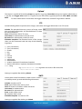
Accessing the Camera
In order to access the camera, it has to be connected appropriately. For more information see ParkIT Install Guide.
For communication with the camera, camera commands have to be used. The easiest way of handling these
commands is through the web interface of the camera. For more information on other communication methods
see ParkIT Programmer’s Manual.
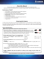
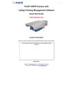
Access from Browsers
Steps of accessing the web interface of the camera from a browser:
1. Connect the camera to a computer or network switch then power on the camera.
After it is powered on, both status LEDs (red and green on the camera front) are turned
on while the camera is booting. After finished, the green status LED flashes two times
while the red one turns off signaling that the camera is ready for operation.
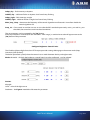
2. Enter an alternate IP address (or set your computer’s IP)
in the 192.0.2.x subnet – where x is an integer number
between 1 and 254 except 3 – with the subnet mask of
255.255.255.0.
3. Use the ping command to test the communication with the camera
Windows:
C:\>ping -t 192.0.2.3
Linux:
username@mylinux:~$ ping 192.0.2.3
4. Soon, the ping package returns: Reply from 192.0.2.3. If not:
o first check the Ethernet LEDs at the PC or the switch side
o check whether the IP address is set correctly; the own IP address of the PC can be pinged.
o proxy is set in the browser or the browser is not set to offline.
If these obstacles are checked and there is still no reply, power off then on and enter the previous ping
command again.
5. Start a browser then enter the default IP address of the camera into the address bar
(http://192.0.2.3). After this, the camera starts with administrator privileges, ready to be set up and
configured.
For more information on accessing the camera, see ParkIT Install Guide.
ParkIT User’s Manual
Page 3/41
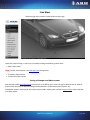
Live View
The live image of the camera can be viewed on this page.
Under the camera image, a status bar is located providing the following information:
date & time (GMT)
NOTE: To alter date and time, see Date and Time configuration.
IP address of the camera
current FPS of the camera
Saving still images and video streams
With the help of the http://IP/scapture command it is possible to get a camera image (in JPEG format) in order to
examine the size of it or to check the height of the characters on the license plate in pixels, etc.
The MJPEG stream is displayed by the camera on port 9901. Entering the command http://IP:9901 will provide the
live video stream.
ParkIT User’s Manual
Page 4/41
Configuration Wizard
The ParkIT camera must be configured before using. Use the Configuration Wizard for setting up camera features
(e.g. zoom, focus etc.) quickly and easily. The wizard guides users through the main calibration steps configuring
various properties of the camera including the Event Manager. Of course, the use of the wizard is optional –
camera properties can be set manually as well.
Steps of the Configuration Wizard:
Step 1: Set network settings to communicate with the camera. See Network Setup for more information.
Step 2: Time and date settings. For more information see Date and time.
Step 3: The Wizard can optimize the camera for ANPR (Automatic Number Plate Recognition) or Overview
purposes. Select the one that is appropriate for your purposes.
Step 4: With the help of the Automatic Zoom (ZFG - Zoom From Geometry) feature, optimal character size on the
camera image for ANPR can be reached quickly and easily. To use autozoom, enter the required data (e.g.
distance of the number plate) into the textboxes then click next. Click ‘Skip’ to set zoom manually.
Step 5: Based on the values provided in the previous step, the camera creates a red rectangle that should include
the license plate completely. If not, then adjust the position of the camera in order to do so.
Step 6: Use the Autofocus feature to achieve sharp camera image. The focusing process can operate on the entire
camera image or on a specified section of it. Use the rectangle to select the area for the Autofocus.
Step 7: Configure the basic camera parameters. For more information see Easy Setup description.
Step 8: Configure triggering and trigger events. For more information see Event Manager description.
Step 9: Set or create camera profile. For more information see Profiles.
ParkIT User’s Manual
Page 5/41
Setup
NOTE: all set parameters are saved only in case of software restart! In case of hardware reset all unsaved changes
will be lost!
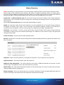
Profiles
Under the profile menu, the list of profiles can be viewed. Camera profiles are pre-set camera configurations
containing a complete set of settings that are loaded at startup and cannot be changed at runtime. One of the
profiles has to be always active and the active profile cannot be deleted.
The camera has a pre-defined default profile that cannot be erased but altered only or Set as current by users.
NOTE: To activate new profiles the camera must be restarted.
Creating new profiles
New profiles can be created according to the followings:
1. Click Create new on the ‘Profiles’ page.
2. Customize the new profile by setting the parameters of the ‘HTTP server’, ‘Hardware layer’ and ‘Live view
setup’ menus.
3. Enter a name for the new profile and click Save.
NOTE: Maximum 32 different profiles can be created.
Export profiles
Settings of camera profiles can be saved into a .tar.gz file, ready to be uploaded to other ParkIT cameras. The name
of the file will contain the exact date and time of exporting as follows: yyyymmdd_hhmmss.tar.gz
E.g. 20120620_101422.tar.gz
The saved settings can be uploaded to other ParkIT cameras by browsing the .tar.gz file in the Setup/Update page.
Export profiles, users and groups
Besides saving all profile settings into a .tar.gz file –just as in case of ‘Export all profiles’–, this option also saves
user and group configurations. The result will be a compressed .tar.gz archive as detailed in the previous option
and can be uploaded to other ParkIT cameras in the same way.
ParkIT User’s Manual
Page 6/41
Editing Profiles
HTTP Server Setup
NOTE: HTTP Server options (except ‘Name of the server’) are read only and cannot be altered by users.
HTML rootpath: Path of the static files (HTML pages, images etc.).
Listen port: Port used by the web server, the default is 80.
Max. connected clients: Maximal number of connected clients (to the web server) at the same time. Maximal
value is 64.
Max. sessions: Maximal number of sessions at the same time.
Max. opened modules per session: Maximal number of opened modules per session at the same time.
Session timeout (seconds): Maximal length of a session, max 3600 seconds (60 minutes).
Filter module: If defined, then queries are only transferred to the module specified here.
Default module: If no module with the specified name/type has been found, then the module specified here is
called.
Name of the server (title of the website): Text appearing in the address bar of the browser.
Click Save to save the settings.
ParkIT User’s Manual
Page 7/41
Hardware Layer Setup
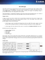
Capturing
Image capturing frequency of the sensor:
The image capturing frequency of the sensor
determines the number of frames the sensor
captures in one second. Note that the actual
number of frames processed by the camera
can be further reduced with the help of the
Skipping frames and Number of skipped
frames (see next chapter) options.
This option can be used for reducing mains
flickering –caused by artificial light sources–
on the camera image. By this value, the
camera can be synchronized to the mains
frequency of its environment (230V@50Hz or
110V@60Hz).
Skipping frames: Frames captured by the
sensor can be skipped and omitted from
processing.
0 = no skipping, the system processes all
images
1 = every second frame is processed
7 = every eighth frame is processed (it
drops 7 frames than keeps one)
Number of frames per second: This option calculates the actual FPS value from the Image capturing
frequency of the sensor and the Skipping frames values.
Flashing
Number of flashes on the built-in illuminator in one second: Flashing frequency of the illuminator.
Image rotating, mirroring
The system is capable of rotating and mirroring images.
Rotate in degrees (0 or 180). Camera image rotation in degrees.
Horizontal mirroring: If ticked then horizontal mirroring is enabled.
Vertical mirroring: If ticked then vertical mirroring is enabled.
Image buffering
NOTE: Image buffering parameters are read only.
Reserved memory size for the GXD system (Mbytes): Maximal size of memory for the system. The rest of the
memory is used as image buffer. This memory is dynamic, if the system needs more memory it allocates for
itself automatically.
Maximal size of an image: Max. size of images in the camera memory.
ParkIT User’s Manual
Page 8/41
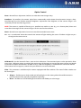
Live View Setup
The camera is capable of streaming live image with four parallel configurations. Number of configurations to be
used can be set at Number of servers (default: 1). Settings for each configuration can be specified in the
corresponding Server sections.
Server options:
Port of the server: Default: 9901.
Number of skipped frames: The number of frames
reduced at the Skipped frames option on the
Hardware layer setup page can be further divided here
by omitting frames from the image stream.
Type of the container:
MJPEG (only if the image channel is set to live
image)
JPEG sequence (only if the image channel is set to
live image)
NOTE: JPEG sequence stream cannot be viewed in
browsers.
Image Channel: The source of images the camera transmits can be of two types: Camera image and Motion
detection image.
Maximum number of simultaneous connections: Default: 2.
Idle connection limit (in milliseconds): Default: 10.
Frame limit: Connection is closed as the number of frames the camera has sent reaches this value.
Default: 0 (0 = no limit).
Connection time limit: Connection is closed after this time is up. It represents the maximal length of
connection time in seconds. Default: 0 (0 = no limit).
Values are applied after clicking Save.
ParkIT User’s Manual
Page 9/41
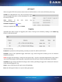
Users
NOTE: At the first occasion, the camera automatically starts with administrator rights. In order to create new users
and groups, a user with ‘admin’ privileges must be created first.
Settings related to users can be managed on this page. The camera handles users on five different access levels
(detailed below). Users can be deleted and edited with the corresponding buttons. Note, that edited user settings
will be applied only after restarting the camera.
Adding new users
New user profiles can be created after clicking on Add new user. In the appearing form, data of the new user must
be provided into the corresponding fields.
Access level of the logged out users: The camera can be enabled to be accessed by users who are not logged in.
The access level of such users can be set up by this option.
NOTE: Users with ‘Guest’ access level cannot be created; this access level can be set up as ‘Access level of the
logged out users’.
Change password of the ‘root’ user: Password of the Administrator level user can be changed here.
NOTE: Only numbers and the letters of the English alphabet can be used in passwords and user names. Settings
are applied after clicking Save.
Access levels of the ParkIT camera
Access level
Guest
Viewer
Normal user
Power user
Administrator
Privileges
no privileges, only login page
live view
help
log in/out
live view
help
login/log out
easy setup
advanced setup
motion detection
event manager
diagnostics/camera log
certain steps of the Configuration Wizard (see page 5)
live view
help
login/log out
easy setup
advanced setup
event manager
diagnostics/camera log
profiles
restart
Configuration Wizard
access to every camera feature
ParkIT User’s Manual
Page 10/41
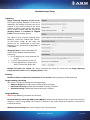
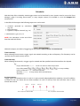
Date and Time
Manage date and time settings of the camera easily on this
page according to the followings:
Setting camera time
I.
Manually
Type the Date and Time values into the corresponding
checkboxes then click Set these values.
II. Automatically
a) Adopt the time of the PC
Click Get the time of the PC to adopt time and date
settings of the PC connected to the camera then click
Set these values.
b) NTP synchronization
NTP synchronization is supported to ensure accurate
time consistently on the camera.
1. Enable NTP synchronization (tick NTP sync
enable).
2. Enter the hostname or IP address of an NTP server
into the NTP server hostname/IP field.
3. Click Save settings to apply changes (a short camera restart is necessary).
4. Click Get the time of the NTP server.
5. Click Set these values.
Use Time Zone option to set the time zone according to your region. Click Set these values to apply new time
zone.
NOTICE: The camera has an internal battery feeding its Real Time Clock (RTC) while the camera is powered off. If
this battery is low or down then the camera clock is reseted every time it is disconnected from power. In case of
such a problem, contact ARH Support Team.
ParkIT User’s Manual
Page 11/41
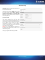
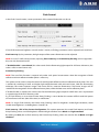
Network Setup
Hostname: The host name of the camera has to
be entered into this field.
The camera can operate in DHCP mode in which
the camera queries the IP address, Netmask,
Gateway, Primary DNS IP and Secondary DNS
IP from the server. Otherwise, these values have
to be set by the user.
IP version 4 and 6
The camera supports IPv4 and IPv6. Both
versions can be enabled simultaneously, but at
least one version must be set. When using IPv4,
the IP address for the camera can be set
automatically via DHCP, or a static IP address
can be set manually. Note that only IPv6 fixed
IPv6 addresses are supported.
NOTE: In case of IPv6 addresses /16 stands for
the length of the subnet mask (16 refers to an 8
character long mask).
Settings are applied after clicking on Save.
ParkIT User’s Manual
Page 12/41
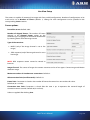
Easy Setup
Image
Focus - Manual focus adjustment. Set focus to make the camera image sharp.
Start Autofocus - By autofocus, the camera adjusts focus automatically until it detects that the camera image is
sharp. Autofocusing may also include automatic brightness adjustment if the brightness of the camera image is
not satisfactory for the autofocusing process.
Zoom - Manual zoom adjustment. Set zoom to reach the intended camera view.
BrightNow! - The BrightNow! function automatically adjusts gain, shutter and iris to achieve the selected target
value (Brightness target). With the help of BrightNow!, the optimal brightness of the camera image can be reached
quickly but less accurately. When the target level is reached, the camera switches back to the previously set
autobrightness mode.
Brightness target - The following automatic brightness strategies set and maintain the value set here.
Brightness Control Mode - Strategy of the brightness controller
Manual - In manual mode, the values of gain, shutter and iris can be adjusted manually.
ANPR - Strategy appropriate for ANPR camera purposes The ANPR strategy does not let any pixels to burn
out.
Overview - Strategy appropriate for overview camera purposes. This mode allows some pixels to burn out.
Quick - The Quick controller method adapts to the brightness changes of the camera environment quickly.
This strategy is suitable for special overview purposes.
NOTE: Flash intensity cannot be adjusted in case of 1.3MP camera models.
Flash Intensity: - The light intensity of the camera’s built-in infrared illuminator can be set by this option. Note
that prolonged direct exposure to infrared light can cause permanent damage to the eye!
Image Post Processing
NOTE: For more information on the parameters, see Advanced Setup description below.
Brightness - Brightness of the camera image can be adjusted manually.
Contrast - Contrast of the camera image can be adjusted manually.
ParkIT User’s Manual
Page 13/41
Advanced Setup
Image Setup
Gamma - Gamma correction used on the camera image.
Brightness - Brightness of the camera image can be adjusted manually.
Contrast - Adjust this control to change the contrast of the camera image.
Whitelevel - Defines the highest pixel value that will be mapped to white. This will be the ending point of the
gamma curve. Values between 0 and 1.0 are valid.
Black level - Defines the lowest pixel value that will be mapped to black. This will be the starting point of the
gamma curve. Values between 0 and 1.0 are valid.
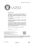
NOTE: Incorrect whitelevel and blacklevel values may cause entirely black or entirely white camera image. In such
cases, reset the whitelevel and blacklevel values to default (whitelevel=1 and blacklevel=0) to restore the camera’s
live view. See Appendices to inspect the effect of adjusting the main image properties.
Compress Rate - The quality of the captured images can be set. The lower this value is, the better the quality of
the images will be. Note, that images of better quality are greater in size therefore, they increase network load. For
that reason it is not recommended to set this value below 20. The network transmission must not go over 40 MBit
(~4MByte/sec), so the image quality should be chosen according to this.
E.g. if the size of an image is 35 kBytes and the images are transmitted with 30 FPS, it means: 35*30 kBytes/s = 1050
kBytes/s ~ 1 MByte/s.
Parameters for Color Cameras Only
Wb. Red, Wb. Green, Wb. Blue - Red, green and blue channel gains.
Saturation - The intensity of colors can be adjusted by saturation. See appendices to inspect the changes of
saturation value.
Color compensation - Color correction can be used to achieve the best color fidelity in captured images by
compensating the color of the dominant light source illuminating the scene. The following options can be set for
different light sources:
Incandescent tungsten, (CCT=2865 K)
Average Summer Sunlight, (CCT=6500)
Cool White Fluorescent, (CCT=4300 K)
North daylight, (CCT=7500 K)
Mid-morning Daylight, (CCT=5500 K)
Auto - Auto compensation
Overcast Sky, (CCT=6000 K)
Off - No light source compensation
Settings can be reseted to the defaults by clicking on Default Settings.
ParkIT User’s Manual
Page 14/41
Brightness Control
Enable Auto Brightness - If auto brightness is enabled, automatic strategies are used to adjust the brightness of
the camera image.
Brightness Target - The following automatic brightness strategies set and maintain the value set here.
Manual - In manual mode, the values of gain, shutter and iris can be adjusted manually.
ANPR - Strategy appropriate for ANPR camera purposes The ANPR strategy does not let any pixels to burn
out.
Overview - Strategy appropriate for overview camera purposes. This mode allows some pixels to burn out.
Quick - The Quick controller method adapts to the brightness changes of the camera environment quickly.
This strategy is suitable for special overview purposes.
Parking – this strategy is appropriate in case of slow motion vehicles (from firmware version 1.12.0.22).
The iris can not be altered in this strategy.
Auto Brightness Mode - The current strategy is displayed and can be selected here.
Light condition - Brightness settings can be set for day and night light conditions respectively. The light condition
returns the value day or night based on the camera light sensor.
Gain - Gain is the extent to which the strength of a video signal is boosted. Note that high gain values result in
noisy images.
Iris - Iris is a mechanical device that controls the amount of light reaching the sensor. If 0 then no light can pass
through to the camera sensor.
ParkIT User’s Manual
Page 15/41
Shutter - Controls the length of exposure time. Too high shutter values may result in blurred images.
Histogram - Enable it to draw image histogram on the camera view.
BrightNow! Target - The BrightNow! function automatically adjusts gain, shutter and iris to achieve the selected
target value. With the help of BrightNow!, the optimal brightness of the camera image can be reached quickly but
less accurately. When the target level is reached, the camera switches to the previously set mode.
NOTE: Flash Intensity cannot be adjusted in case of 1.3MP camera models.
Flash Intensity - The light intensity of the camera’s built-in infrared illuminator can be set by this option. Note that
infrared light can severely damage the human eye. Do not look into the light source directly.
Set - Click Set to assign different Flash Intensity values for each Auto brightness mode respectively, according to
the followings:
1. Select the Auto brightness mode and Light condition to which you want to assign a Flash intensity value (at
Mode and at Light condition).
2. Set the desired Flash Intensity value (at Flash Intensity).
3. Click Save.
As a result of this procedure, the set Flash Intensity values will be applied for the assigned Mode and Light
condition automatically when changing Auto brightness mode.
ParkIT User’s Manual
Page 16/41
Configure Parking Brightness Control
The following HTTP requests are available from firmware version 1.12.0.22.
With the camera IPaddress/plainconfig/parkingbc.htm HTTP request all parameters related to the brightness control
of the parking mode can be displayed.
The name of the parameter, its measure, minimal and maximal value (parameter value limits), the default value,
step and the attribute (whether it is writeable or read only) can be seen here.
Parameters of the Parking mode:
Target – target of the control. Thresholds: dark image (-100) or bright image (+100). See BrightNow! Target.
Histeresis [%] – determines the boundaries of the tolerance interval. If the median falls out of this interval the
control starts.
Mode – 0: the control is turned off
1: night mode
2: day mode
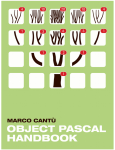
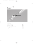
Median – Read only parameter. An index number that is intended to provide information on how dark or bright is
an image. The median separates the amount of dark pixels from the bright pixels equally on the
histogram. On the image below the median is indicated with a white line in the middle of a histogram.
To provide an excellent image quality, in an ideal case the value of the median should be between 85
and 100.
Burn – Read only parameter. Number of burned out pixels.
Nsteps – Read only parameter. Number of interventions from the camera start.
Iris_min – minimal iris value
Iris_max – maximal iris value
Iris_step – extent of the steps
Gain – gain value for image capturing
Shutter – value of shutter in μs
Gamma – gamma correction on the camera image
Daynightcut – under this rate the control does not take effect (the environment is too dark, to reach the target)
Daynighthist – it determines the range around the daynightcut, which influences the day/night transition.
For example: if the daynightcut is set to 70 and the daynighthist is set to 5, if the value reaches 65
the day mode will turn into night mode and in case of 75 the night mode will turn into day mode.
In this way the status will not alter between the boundaries.
Auto_filter – responsible for the filter switch
1: IR/Cut is turned on in day mode
2: All pass filter is turned on in night mode
Auto_modesw – switching of the modes
1: the switching is automatic
0: stays in a previously set mode
ParkIT User’s Manual
Page 17/41
Ledpc_day – Flash Intensity at daytime
Leddiff_day – odd/even flashes at daytime. See Frame Parity Flashing
Ledpc_night – Flash Intensity at night
Leddiff_night – odd/even flashes at night. See Frame Parity Flashing
Main_loop_sleep – determines the frequency of the control algorithm in milliseconds. How often should the
control algorithm run.
Snap_iris – if it is turned on and the user sets an iris value that falls outside the previously set iris_min and iris_max
threshold, the control restore it into these boundaries.
The set parameters can be accepted by the [Set] button.
If the set parameter is incorrect (falls out of the MIN – MAX range), a standard error code will appear next to the
[Set] button of the parameter:
Configure Brightness Control Limits
The IP address/plainconfig/bclimits.htm HTTP request provides settings belonging to the current mode (Anpr,
Overview, Quick [Indoor]).
The below parameters specify when the camera has to switch between the day and night modes.
Mode: the mode – of which the brightness control limits has to be configured – can be selected
Section:
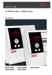
daynight
Level – value of the light sensor
Deadzone – the Figure1 intended to illustrate this parameter
ParkIT User’s Manual
Page 18/41
Figure1
Seconds – minimum waiting time between switches.
In the day_limits and night_limits sections the user can define the limits between which the control should
operate.
ParkIT User’s Manual
Page 19/41
Optics Control
Focus - Manual focus adjustment. Set focus to make the camera image sharp.
Autofocus - By autofocus, the camera adjust focus automatically until it detects that the camera image is sharp.
Auto-focusing may also include automatic brightness adjustment if the brightness of the camera image is not
satisfactory for the auto-focusing process.
NOTE: The camera is capable of focusing to a specified area within its view (e.g. on a license plate). Move and
resize the red rectangle on the camera image to set this area for the autofocus.
Zoom - Manual zoom adjustment. Set zoom to reach the intended camera view.
Iris - Iris is a mechanical device that controls the amount of light reaching the sensor. If 0 then no light can pass
through to the camera sensor.
Calibrate All - Use this button for focus, zoom and iris calibrations. The motorized optics can be operated in finite
many steps. Calibration means rescanning the entire range of the optics to measure the exact position and length
of control to compensate deviations (if there are any). If the auto brightness is enabled the iris cannot be altered.
If this button does not appear, it means that your device has not to be calibrated.
Filter - This parameter is available only for cameras equipped with filter switchers. The state of a filter switcher can
be of two types:
All pass - The filter passes both visible and infrared light, use this setting when infrared illumination is
present and necessary (typically at nighttime capturing).
IR cut - The filter cuts out infrared light to maintain color fidelity on color images.
ParkIT User’s Manual
Page 20/41
Flash Control
In the Flash Control section, various parameters of the camera illumination can be set.
If one of the automatic brightness control modes is active, its flashing parameters can be adjusted and saved here.
Flash Intensity: By this parameter, the light output of the camera illuminator can be adjusted.
NOTE: In case of 1.3MP camera models, adjusting Flash Intensity and Frame Parity Flashing are not supported –
they can only be turned on/off.
If ‘Enable/Disable’ is not selected, this value stands for the illuminating light output for all frames. Otherwise, this
value is valid on even frames only.
Frame Parity Flashing
NOTE: The use of this function is required only under such special circumstances when the recognition of both
reflective and non-reflective number plates is necessary.
This option can be used to setup the camera for reading both reflective and non-reflective license plates. This task
is realized by switching to lower and higher light output between odd and even frames. With this illuminating
technique, the camera captures images with more and less intensive illumination. The former images will be
suitable for the recognition of non-reflective license plates, while the latter ones are for reflective plates.
If ‘Enable/Disable’ is selected, this value stands for the illuminating light output for odd frames and is represented
as a percentage of the Flash Intensity value.
E.g. if Flash Intensity is set to 50 and Frame Parity Flashing is set to 20 then the camera will flash with 50% power
on even frames and 10% (20% of the 50%) on odd frames.
NOTE: To assign Flash Intensity and Frame Parity Flashing values for brightness modes/light conditions, check
‘Enable Auto Brightness’ on the Brightness Control Tab.
Flash Intensity / FPF of the Current Configuration: This option represents the saved Flash Intensity and Frame
Parity Flashing values saved for brightness mode and light condition set at Mode and Light condition.
By clicking on Save, the set Flash Intensity and Frame Parity Flashing values are saved to the set Mode and Light
condition.
ParkIT User’s Manual
Page 21/41
Motion Detection
NOTE: This feature has to be ignored in case of using LetUgo automated entry and exit control software product.
With the help of the hardware motion detector, the camera is capable of detecting motions in image streams
based on the pixel differences between consequent frames. This motion detector can be customized for different
purposes through its settings detailed below and can be used to launch trigger events on motions.
Actual View - In Motion detection view, the live camera image can be seen to help to setup motion detection.
Note that this view is intended to help the setup process, the quality of the image stream is not appropriate for
other purposes.
When clicking Set to mask view, the mask toolbar (detailed below) appears.
Speed - By setting the speed of the motion detector, it can be specified that how fast pixel changes should be
considered as motions. If this value is set too low then slow ambient brightness changes (e.g. cloudy/sunny
weather) may be considered as motion. If set too high, even a lightning can trigger signaling motion.
Sensitivity - By sensitivity, it can be set that what extent of pixel changes of the camera image should be
considered as motion. If low, then minimal pixel changes are sufficient to cause motion, if high, only great pixel
changes initiate motion.
Frame sensitivity - Sensitivity of the motion detection frame.
Reslevel - Motion limit. The extent of pixel changes below which the detected motion is ignored (the ‘motion’ text
does not appear).
Sequence - Images containing motion are arranged into sequences. These sequences have unique IDs.
Sequence frames - The index of frames within the sequences.
Difference from background - This value represents the extent of difference between the previous and the
current image. The higher this value is the more motion has occurred.
Motion value - This value shows the extent of motion on the current image. This value is based on the sensitivity,
speed and difference from background.
Motion rectangle - The area in which motion has occurred is framed by a motion rectangle defining the place of
motion in the image. This option returns the coordinates of the motion rectangle.
ParkIT User’s Manual
Page 22/41
Masking - With the help of image masking, certain parts of the camera view can be ignored by the motion
detector. This feature is designed for situations when not the entire camera image is interesting for triggering (e.g.
if the camera covers two lanes but only one of them is observed by the user).
Creating mask
1. Click Mask View.
2. Select the Brush size (the amount of pixels to be masked on one click).
3. Move the mouse cursor on the camera image and click on the area to be masked. Repeat this step as
many times as necessary to mask the desired area(s).
4. Click Save Mask.
Modifying mask
A. Erase
Click Clear All to delete the entire mask.
Check Erase and click on the masked area(s) to be deleted.
B. Fill
Mask the entire camera image by clicking on Fill All.
C. Invert
When selecting invert, masked areas can be erased and unmasked areas can be masked by simple mouse
clicks. The size of the brush can be adjusted in case of inverting as well.
D. Restore
Return to the previously saved mask by clicking on Restore Mask.
ParkIT User’s Manual
Page 23/41
Event Manager
The camera can be set up to execute tasks on various occasions (e.g. to upload images when it detects motion).
These occasions are called triggers (in the above example: the detection of motion) while executed tasks are
called trigger tasks (in the example: uploading images). Currently, one trigger task (uploading images) is
provided with the camera, but adding further tasks is possible.
The Event Manager is responsible for deciding at each time instant if the prescribed trigger task should be
executed. This decision is based on the state of the trigger sources at the given time instance.
Trigger sources
A trigger source has two states: asserted and not asserted. Being asserted means being active. A trigger source
may have multiple outputs: this is like having multiple instances of the same trigger source (each may be
configured differently), but handling them together.
Basically, trigger sources can be of two types:
external trigger: signals arriving from the trigger input or the user UART of the camera, triggers sent from
the client software programmatically or manually (by clicking on the button on Software Trigger page)
internal trigger: the motion detector of the camera, or scheduled (see Configure Scheduler) by the user
By default, there are five trigger sources:
Hardware Motion Detection
Software trigger
UART trigger
GPIO trigger
Scheduler trigger
Every trigger source can be assigned with a letter (capital letters of the English alphabet from A to V, see figure
below). When configuring through the web interface, it is done automatically. The Event Manager will identify the
trigger source using this letter. The trigger sources to be used can be selected by registering them with the Event
Manager.
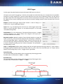
Simple events
In the simplest case, the execution of
the trigger task depends only on one
trigger source. In this case, by simply
writing the letter of a trigger source
into the formula box, trigger event
(upload set on the upload page)
occurs when trigger signal arrives on
the source associated with letter. E.g. if
the UART trigger is assigned with the
letter C and C is written to the formula
box (see figure) upload will occur on trigger signals arriving through UART. It is not even necessary to register any
other trigger source in this case.
ParkIT User’s Manual
Page 24/41
The formula is applied (marked with green arrow after the formula box) right after clicking Start and can be
invalidated (marked with red arrow after the formula box) by the Stop button. When clicking Reset, all the
registered sources are deleted.
Complex events
In case of complex events, upload depends on more than one trigger sources. To express relationships between
the sources, logical operators can be used. Available logical operators: AND(&), OR(|), NOT(!).
You can use two shorthands 'any' and 'each', which mean 'launch trigger task if any of the registered sources is
asserted' and 'launch trigger task if each of the registered sources is asserted' respectively.
Example A:
Let ‘A&B’ be set where:
A is the Hardware Motion Detector
B is the Scheduler
This setup may correspond to a situation where traffic monitoring is only necessary at some times of the day: e.g.
we want to upload images containing motion e.g. from 6 to 11.
With this setup, the trigger task (uploading of images) will be executed only when both the Scheduler and the
Hardware Motion Detector are asserted, so, both trigger signals at the same time are necessary to start uploading.
Example B:
Let ‘A|B’ be set where
A is the Hardware Motion Detector
B is the GPIO trigger
This setup may correspond to a scenario where an inductive loop is used to send triggers (through GPIO) when it
detects motion and the camera Hardware Motion Detector is also used to support the loop (in case of pedestrians
or vehicles that can be barely detected by the loop (e.g. bicycles). If ‘A|B’ is set then upload occurs when a trigger
signal arrives on the GPIO or from the Hardware Motion Detector or both, so, either trigger signal is sufficient to
start uploading.
Brackets can also be used in the formulas to express complex relationships:
Let ‘(A|B)&!C’ be set where
A is the Hardware Motion Detector
B is the Scheduler
C is the UART trigger
In this case, trigger event occurs only if
1. motion is detected
2. the Scheduler trigger is asserted
3. trigger signal does not arrive on the UART
at the same time.
NOTE: Spaces are not allowed in formulas.
ParkIT User’s Manual
Page 25/41
Software Trigger
By using the software trigger source, triggers can be sent to the camera either from user applications or using the
Send Trigger button on the web interface. The time of trigger start and trigger end can be brought forward or
delayed by Start offset [ms] and End offset [ms]. Settings are applied after clicking Submit.
UART Trigger
The camera can be triggered through its UART. Besides the common UART properties (baudrate, byte size, parity,
number of stop bits) the communication protocol can also be specified here.
An UART trigger event starts with a Trigger Start Token (TST) byte, then max. 254 bytes of trigger data may
follow, and then it ends with a Trigger End Token (TET) byte. The trigger start timestamp will be the system time
at the instant the TST arrives, plus the Start Offset, while the trigger end timestamp will be the system time at the
instant the TET arrives, plus the End Offset. Trigger data (including the TST and TET) will be forwarded to the Event
Manager along with the image.
It is possible to specify the byte value of the TST (e.g. entering 0x0A means the trigger will begin with a '\n' byte) or
check 'Start on first byte', which means, whatever byte comes first or follows the last end token will be the trigger
start token.
Trigger task (upload) can be set to be launched at various stages of a trigger signal:
1. Level Mode
In case of level mode, trigger task is executed continuously until the end of the trigger signal:
1
0
Trigger End
Trigger Start
2. Rising Edge Mode
In case of rising edge mode, trigger task is executed once, at the moment when the trigger signal arrives:
1
0
Trigger End
Trigger Start
3. Falling Edge Mode
In case of falling edge mode, trigger task is executed once, at the moment when the trigger signal ceases:
1
0
Trigger End
Trigger Start
ParkIT User’s Manual
Page 26/41
GPIO Trigger
On this page, the general purpose input and output (GPIO) ports can be set.
GP input can be used for triggering. To do this, the sample rate with which the port is sampled must be specified.
Note that if a high sample rate is set then erratic behavior may occur due to bouncing. Always use the lowest
possible sample rate. The voltage level can also be set that corresponds to the logic '1' level. A constant offset can
be added to the assertion (making active) and the de-assertion (making inactive) of the GP input with start and
end offset.
Output: If ticked, the trigger output of the camera is active. If empty, it is
inactive. This is e.g. for opening the barrier.
Input: This is e.g. for detecting the arrival of a car. If the trigger input of the
camera is active, the bulb is green. It is red when the input is in an invalid
state (debouncing failed).
Sample Rate: This is for debouncing. The General Purpose Input is sampled
with this frequency (e.g. 100 Hz means the voltage on the input pin is
measured 100 times in a second.)
Required samples: Minimal number of equal valued samples to accept the
input as active. E.g. we measure the voltage on the GP input pin a 100 times a
second (Sample Rate=100). A ‘required samples’ value of 10 means that we
must measure 'high' voltage consecutively 10 times in order to accept the pin
as active, without measuring any 'low' values in between. This parameter is
for debouncing as well.
Logic ’1’ voltage level: Defines which voltage value (low or high) represents the logic value of '1', that is when is
the trigger input considered to be ’Active’ by the camera. E.g. if it is set to 'low', then the input is in a 'high' state by
default, and if voltage drops to 'low', a trigger event is generated.
Start offset [ms]
This amount of delay will be added to the start timestamp of the trigger event.
Possible values in milliseconds: -10000 <-> +10000
End offset [ms]
This amount of delay will be added to the end timestamp of the trigger event.
Possible values in milliseconds: -10000 <-> +10000
ParkIT User’s Manual
Page 27/41
With the help of two outputs, trigger task cannot be launched only on the preconfigured modes (level, rising edge,
falling edge -see UART description above) but on ‘custom’ modes combined from the mentioned ones. E.g. Setting
Output 0 to Rising edge and Output 1 to Falling edge, upload can be set to occur on trigger start and trigger
end:
1
0
Trigger End
Trigger
Trigger mode
Trigger task (upload) can be set to be launched at various stages of a trigger signal:
1. Level Mode
In case of level mode, trigger task is executed continuously until the end of the trigger signal:
1
0
Trigger End
Trigger
2. Rising Edge Mode
In case of rising edge mode, trigger task is executed once, at the moment when the trigger signal arrives:
1
0
Trigger End
Trigger
3. Falling Edge Mode
In case of falling edge mode, trigger task is executed once, at the moment when the trigger signal ceases:
1
0
Trigger End
Trigger
ParkIT User’s Manual
Page 28/41
Scheduler
With the help of the scheduler, timed trigger events can be launched by users (events must be set on the ‘Event
Manager’ page). For timing these events, as many outputs (timers) are available as set in the Output field
(maximum 2).
In the fields of the outputs the following expressions can be used:
numerals separated by semicolons
(e.g. 6;9)
the word ‘every’
hyphens to express intervals (e.g. 7-9)
+ combinations e.g. 6;7;9-11;15
NOTE: Use semicolons at the end of the
lines the mark end of data.
Within the outputs, two kinds of triggering can be specified: time instance and time interval.
Time instance(s)
When selecting time instances, trigger signals are emitted according to the set frequency. This frequency can be
set from once a month to every second.
Time interval(s)
When selecting time intervals, a trigger signal is emitted until the specified second/minute/hour has elapsed.
E.g.
Day(s) of the month: 12;15 – on the 12th and 15th of the every month
Days of the week:
– on every weekday
Hour(s) of the day: 6-8; – from 6am until 8am
Minute(s): every – in every minute of the selected hour(s)
Second(s): 0
As time instances:
Trigger signals are emitted on the 12th and 15th in every month, independently from weekdays (since all weekdays
are ticked it does not matter that on which weekday 12th and 15th will be), from 6am until 8am once in every
minute at 0 seconds.
06:01:00
06:02:00
06:03:00….
1
0
Tue, 12 Apr 2011 06:00:00 GMT
Tue, 12 April 2011 08:00:00 GMT
ParkIT User’s Manual
Page 29/41
As time intervals:
Trigger signals are emitted on the 12th and 15th of the every month, independently from weekdays (since all
weekdays are ticked it does not matter that on which weekday 12th and 15th will be) and asserted from 6am until
8:59:59.99 am.
1
0
Tue, 12 April 2011 08:59:59 GMT
Tue, 12 Apr 2011 06:00:00 GMT
Settings are saved after clicking Submit.
The target for uploading on scheduler trigger can be set by clicking the Configure Upload Target button, right
after submitting changes.
ParkIT User’s Manual
Page 30/41
Upload
The camera is capable of forwarding Images (image files e.g. jpegs), Event data (image and capture information in
a .par file) and Trigger information (in a .trg file) via one of the three supported protocols: FTP, SMTP and HTTP
POST.
For more information on event data and trigger information, see ParkIT Programmer’s Manual.
FTP
Set the following fields to upload camera images, event data and trigger information to an FTP server:
Include: The uploaded data may consist of image, event
data and trigger information. Use the checkboxes to select
the one(s) to upload.
Host: the hostname of the FTP server
Username: for authorization to the FTP server
Password: for authorization to the FTP server
Filename template: The filename format of the images
(data) can be customized with the help of the following
arguments:
$y: year (4 characters)
$r: year (2 characters)
$o: month
$d: day
$h: hour
$m: minute
$s: second
$l: millisecond
$t: frametimems
$i: motion sequence ID (hexadecimal number)
$x: frame index within a sequence (hexadecimal number)
text: string
e.g. $d/$h-$m-$s-$l.JPEG argument set results in file names like:
06/11-08-37-957.JPEG
Settings are applied after clicking Submit.
SMTP
Camera data can be forwarded in simple e-mails as well. To
use SMTP protocol, provide the following information:
Include: see above at FTP
Send: type of data to be sent in e-mail
Host: hostname or IP address of the mail server
Username: for authentication
Password: for authentication
From: sender of the e-mail
To: recipient of the e-mail
Filename template: see above at FTP
Settings are applied after clicking on Submit.
ParkIT User’s Manual
Page 31/41
HTTP POST
When using the HTTP POST protocol, camera data can be forwarded to a web server (for further processing).
Include: The uploaded data may consist of image, event
data and trigger information. Use the checkboxes to select
the one(s) to upload.
Host:
Address
of
192.168.0.12/index.php).
the
web
server
(e.g.
Filename Template: See FTP above.
Settings are applied after clicking on Submit.
Logging
Uploaded data and/or images are logged by the camera. The log can be viewed by clicking on the Show Log
button on the Upload page.
Structure of the log:
Protocol: the protocol used for uploading. Currently, it can be FTP, SMTP and HTTP POST.
Filename: name of the uploaded trigger information (.trg) and/or image file according to the set Filename
template (see above).
NOTE: If trigger info uploading is selected (on the Upload tab), a .trg file is uploaded independently of the criteria
set in the Event Manager, while image file is uploaded only if the set criteria (in the Event Manager) are fulfilled.
Included: the type of the uploaded data (image, data or both); uploading of trigger info is indicated in extension
of the uploaded trigger file: .trg.
Status: status of the upload; OK signals successful uploading
Error: this field signals if there was any error during the upload.
ParkIT User’s Manual
Page 32/41
Diagnostics
Diagnostics
Light sensor value [0 – 255]: Value of the light sensor. The brighter the camera environment is, the higher
this value will be. (0 refers to complete darkness). This value saturates at 100% in normal daytime light
conditions.
Temperature [ºC]: Inside temperature of the camera.
Built-in Flash Overdrive: The LED control circuit of the camera turns off the LEDs for a short period
preventing impairment when exceeding safe voltage/FPS values.
Possible values:
No - no overdrive
Yes - the LED control circuit is intervening to protect the LEDs
Memory usage
Total Buffer Memory: size of the image buffer
Free Buffer Memory: size of free memory in the image buffer
Total Device Memory: size of full system memory
Free Device Memory: size of free system memory
Loaded Modules
The name, path and short description of modules is enlisted in this group. For more information, see ParkIT
Programmer’s Manual.
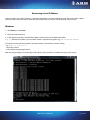
Camera Log
Camera events are logged into the central log file for administrative and error management purposes. The lines
(records) of the log can be filtered for specific events according to the typed in characters. Filtered events are listed
after clicking Submit. Note, that the log file content is erased after restarting the camera. To save log file, enter the
following command into your browser’s address bar:
http://{IP address}/logging/logstream?getlog&ajaxcall=1
The appeared data can be inserted into any text editor by simple copy/paste procedure.
Update
The firmware of the camera can be updated by this option according to the followings: Browse the tar.gz
firmware file then click Update.
Click Export all to save profile, user, group, network and time zone settings as described in the Profile page
description.
ParkIT User’s Manual
Page 33/41
Restart
Under certain circumstances (e.g. when changing camera profile) the camera must be restarted. The restart takes
several seconds after which the camera is ready for operation with saved or default settings.
Help
Open the ParkIT manuals for more information on camera setups and management.
Recovery Mode
The camera has a Recovery Mode primarily designed to maintain the communication with the camera when it is
unreachable for various reasons e.g. due to misconfiguration. The following section is intended to provide you a
complete understanding on the Recovery mode v3.x. The 3.x version can be used in case of cameras with previous
firmware versions as well (from 1.12.0.26 firmware version)! In case of previous versions, please update the camera
at least to version 1.12.0.26.
Entering Recovery mode
Starting of the Recovery mode can be implemented in the following way:
By magnetization:
1.
2.
3.
4.
5.
Power off the camera.
Touch a magnet (not included) to the sunshield of the camera, right in the middle and hold it in
position. See figure below.
Power on the camera and wait 5 seconds.
Remove the magnet.
Reach the camera via its default (192.0.2.3) IP address.
Use the centerline of the camera to
help to locate the position of the
magnet.
The recommended strength of the
magent is 1210 mT (millitesla).
Magnet
Update, Factory and other compressed files
Difference between the files:
Factory-xxx.bin
These files are prepared by the manufacturer and they mean a complete system backup. In case of normally
functioning cameras these should not be used in the cameras firmware update, because it may damage the
well functioning system (it writes files, which may be currently used by the system). These files can be
uploaded by the Recovery mode.
ParkIT User’s Manual
Page 34/41
Update-xxx.bin
These are the so-called firmware update files. They serve for the update of a functioning system. It could be for
example in case of update from the version 16 to 17. However, these cannot be used in the recovery mode
only in normal mode of the camera.
Xxx.cfz
These files contain only configuration settings. For example, if the ‘user’ or ‘image’ settings will be saved and
then reloaded later. Such files should be uploaded to or created on the normal mode of the camera (although
it can be done in the recovery mode as well).
In some cases the extension is not .bin or .cfz, but .tar.gz. In these cases the beginning of the file has to be Factory
or Update.
Web interface of the recovery mode
Information screen
The MAC and the IP address is the same for all cameras at the Recovery mode. But the IP address of the camera can
be altered at the Normal mode part by clicking the [Change] button or at the Network settings part of the Settings
menu item.
ParkIT User’s Manual
Page 35/41
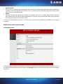
Settings screen
Setting-related backups and restoring can be performed on this screen. Only certain parts of the system can be
managed here, operations concerning the whole system can be performed at the Firmware menu item of the
Recovery mode.
Network settings
At the ‘Network settings’ part the network settings can be altered by clicking the [Modify] button. In this case not
the recovery mode that is modified, but the network settings of the camera operating in normal mode.
User/Password reset
The ‘User/Password reset’ restores the default, factory User and Password.
Restore factory settings
The ‘Restore factory settings’ restores all the default factory settings.
Import settings / Export settings
The ‘Export settings’ creates a .cfz file and saves the settings of the camera into a directory on the PC. The ‘Import
settings’ is able to restore these settings by uploading these .cfz files.
ParkIT User’s Manual
Page 36/41
Firmware screen
Full system backup-related processes can be implemented on this screen. While at the settings menu only certain
parts of the system can be managed, here operations concerning the whole system (settings, programs, complete
operating system etc) can be performed.
Firmware update
At the ‘Firmware update’ part a complete (factory) system can be uploaded to the camera. All settings will be
deleted, except the hardware related environment set by the manufacture (MAC address, panel type, sensor type,
serial number, license file).
Full factory restore
The ‘Full factory restore’ basically behaves as the Firmware update with the difference that this feature uploads a
default factory package. By contrast, Firmware update is waiting for such file from the PC.
Full system backup
The ‘Full system backup’ saves the entire camera settings (the file system operating in normal mode). It can be used
later at the Firmware update part. It cannot be used at the firmware update of an active system in a normal mode
of the camera!
Updates between versions
Minor changes between versions (e.g. from v1.12.0.10 to v1.12.0.26)
Minor changes means, that the first number of the version is the same (v1.x, v2.x or v3.x). In this case only the file
with higher version starting with Update- has to be uploaded at the ‘Update’ part of the Setup menu item of the
camera web interface (in normal mode). The update packages are prepared to handle the smaller updates (e.g.
from v1.1 to v1.2) of the higher versions (v1, v2, v3).
Upgrade of the Recovery mode
Like in case of normal update, a file starting with Update-Recovery- has to be uploaded during the normal
operation of the camera. It can be done at the ‘Update’ part of the Setup menu item of the camera web interface.
After the upgrade of the recovery mode the firmware version of the camera is not altered, only the firmware
version of the recovery mode!
ParkIT User’s Manual
Page 37/41
Recovering a Lost IP Address
If the IP address of a ParkIT camera is unknown (forgotten) it can be reached through the camera MAC address
located on the back of the device. Note that this method can be used for only temporary camera access.
Windows
1. Click Start and select Run.
2. Enter the cmd command.
3. In the appeared window add the MAC address of the camera to the ARP cache table:
arp -s {desired IPv4 address} {camera MAC address separated by hyphens e.g. 00-1d-4d-00-09-B7}
4. Ping the camera with the IP address set above within 1 minute from camera startup.
- e.g.: ping –t 192.0.2.6.
- restart the camera
- wait until the ping package returns
After the ping package has arrived, the camera picks up the IP address and becomes ready to be set up.
ParkIT User’s Manual
Page 38/41
Linux
1. Open a console.
2. Add the MAC address of the camera to the ARP cache table:
arp -s {desired IPv4 address} { camera MAC address separated by colons e.g. 00:1d:4d:00:09:B7}
Windows&Linux
NOTE: In order to access the camera successfully, the desired IP address must be in the same subnet with your
computer. See the MAC address on the sticker located on the back of the camera.
NOTE: The first characters of a MAC address are always 00-1d-4d while the last three hexadecimal numbers are
correspond to the last three characters of the camera serial number (also located on the back of the device).
IMPORTANT: This IP address can be used for only temporary camera access. It must be changed right after
accessing the camera.
ParkIT User’s Manual
Page 39/41
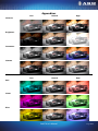
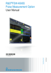
Appendices
Low
Normal
High
Low
Normal
High
Contrast
Brightness
Saturation
Gamma
White balance
Red
Green
Blue
ParkIT User’s Manual
Page 40/41
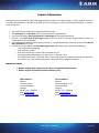
Contact Information
Should you have any problem during operating the ParkIT cameras, our support team is at your disposal. Please try
to explain the problem as detailed as possible and do not forget to send the following information to make it
easier to help you:
The name of your company (for administration purposes).
The exact type of the product you have (serial number is appreciated).
If you have problems during recognition, send images in the original file format.
If there is any error code or message appearing, please send us the code snippet where it occurs (a
screenshot may also be helpful).
If you noticed the problem while running a Demo or a sample application, please let us know the name of
the application you tested.
If you have some problem while developing your own application, please specify the followings:
o your programming language
o your operating system
o the name and version number of the compiler you use
o the programming technology (e.g. native C/C++ / ActiveX / .NET)
o If possible please send a short part of the source code. Please try to determine the place where the
error occurs (e.g. “the scapture?getshutter command returns a negative number…“).
IMPORTANT NOTES:
Before sending back a faulty device, always contact ARH Support Team.
Repairs may be executed by the manufacturer only!
Office address:
ARH Inc.
41 Alkotás Road
HU-1123 Budapest
Hungary
Phone: +36 1 2019650
Web: www.arh.hu
Email: [email protected]
Service address:
ARH Inc.
Ipari Park HRSZ 1113/1
HU-2074 Perbál
Hungary
Phone: +36 1 2019650
Web: www.arh.hu
Email: [email protected]
ParkIT User’s Manual
Page 41/41