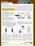
1
WireScope 350
Useròs Guide
www.wirescope.com
WireScope 350
User’s Guide
Part Number N2605A-070
Printed in USA
Version 2.1 Print Date: April 2001
Copyright 1999, 2000, 2001 Agilent Technologies. All rights reserved.
Trademarks
WireScope is a registered trademark of Agilent Technologies. Microsoft is a registered trademark. Windows and Windows NT are registered
trademarks of the Microsoft Corporation.
Warranty
All instruments in this product carry their own individual warranties starting from date of shipment. Duration and conditions of warranty for this
product may be superseded when the product is integrated into (becomes a part of) other Agilent Technologies products. During the warranty
period, Agilent Technologies will, at its option, either repair or replace products that prove to be defective. For warranty service or repair, this
product must be returned to a service facility designated by Agilent Technologies (Agilent). Buyer shall prepay shipping charges to Agilent and
Agilent shall pay shipping charges to return the product to Buyer. However, Buyer shall pay all shipping charges, duties, and taxes for products
returned to Agilent from another country. Agilent warrants that its software and firmware designated by Agilent for use with a product will
execute its programming instructions when properly installed on that product. Agilent does not warrant that the operation of the product, or
software, or firmware will be uninterrupted or error free.
Limitation of Warranty
The foregoing warranty shall not apply to defects resulting from improper or inadequate maintenance by Buyer, Buyer-supplied products or
interfacing, unauthorized modification or misuse, operation outside of the environmental specifications for the product, or improper site
preparation or maintenance.
The design and implementation of any circuit on this product is the sole responsibility of the Buyer. Agilent does not warrant the Buyer’s
circuitry or malfunctions of Agilent products that result from the Buyer’s circuitry. In addition, Agilent does not warrant any damage that occurs
as a result of the Buyer’s circuit or any defects that result from Buyer-supplied products.
NO OTHER WARRANTY IS EXPRESSED OR IMPLIED. AGILENT TECHNOLOGIES SPECIFICALLY DISCLAIMS THE IMPLIED
WARRANTIES OF MERCHANTABILITY AND FITNESS FOR A PARTICULAR PURPOSE.
Exclusive Remedies
THE REMEDIES PROVIDED HEREIN ARE BUYER’S SOLE AND EXCLUSIVE REMEDIES. AGILENT TECHNOLOGIES SHALL NOT
BE LIABLE FOR ANY DIRECT, INDIRECT, SPECIAL, INCIDENTAL, OR CONSEQUENTIAL DAMAGES, WHETHER BASED ON
CONTRACT, TORT, OR ANY OTHER LEGAL THEORY.
Notice
The information contained in this document is subject to change without notice. AGILENT TECHNOLOGIES MAKES NO WARRANTY OF
ANY KIND WITH REGARD TO THIS MATERIAL, INCLUDING, BUT NOT LIMITED TO, THE IMPLIED WARRANTIES OF
MERCHANTABILITY AND FITNESS FOR A PARTICULAR PURPOSE. AGILENT TECHNOLOGIES shall not be liable for errors
contained herein or for incidental or consequential damages in connection with the furnishing, performance or use of this material. This document
contains proprietary information, which is protected by copyright. All rights are reserved. No part of this document may be photocopied,
reproduced, or translated to another language without the prior written consent of Agilent Technologies. AGILENT TECHNOLOGIES assumes
no responsibility for the use or reliability of its software on equipment that is not furnished by AGILENT TECHNOLOGIES.
U.S. Government Restricted Rights
The Software and Documentation have been developed entirely at private expense. They are delivered and licensed as "commercial computer
software" as defined in DFARS 252.227-7013 (Oct 1988), DFARS 252.211-7015 (May 1991) or DFARS 252.227-7014 (Jun 1995), as a
"commercial item" as defined in FAR 2.101(a), or as "Restricted computer software" as defined in FAR 52.227-19 (Jun 1987)(or any equivalent
agency regulation or contract clause), whichever is applicable. You have only those rights provided for such Software and Documentation by the
applicable FAR or DFARS clause or the Agilent Technologies standard software agreement for the product involved.
Contents
CHAPTER 1 ................................................................................................................................... 9
INTRODUCTION.................................................................................................................................. 9
Introduction .............................................................................................................................. 9
System Requirements ............................................................................................................... 9
Items Supplied .......................................................................................................................... 9
Optional Accessories ................................................................................................................ 9
Software Upgrades ................................................................................................................. 10
Standard Warranty.................................................................................................................. 10
Technical Support................................................................................................................... 10
Before you call ...................................................................................................................................10
Viewing software and hardware version information.........................................................................11
CHAPTER 2 ................................................................................................................................. 13
CABLE TESTING OVERVIEW ............................................................................................................ 13
Purpose ................................................................................................................................... 13
Two-ended certification testing .............................................................................................. 13
Test configurations ................................................................................................................. 14
Link configuration ..............................................................................................................................14
Channel configuration........................................................................................................................14
Cabling certification standards ............................................................................................... 15
CHAPTER 3 ................................................................................................................................. 17
WIRESCOPE OVERVIEW .................................................................................................................. 17
WireScope 350 hardware........................................................................................................ 17
Color touch screen user interface.......................................................................................................17
CompactFlash™ memory card slot....................................................................................................17
Digital fault finding ............................................................................................................................18
Ports........................................................................................................................................ 18
SmartProbe test port ..........................................................................................................................18
Serial port...........................................................................................................................................18
USB ports ...........................................................................................................................................18
Talkset jack.........................................................................................................................................18
Charger port.......................................................................................................................................18
WireScope 350 user interface overview ................................................................................. 19
Basic screen layout.............................................................................................................................19
Keys ....................................................................................................................................................20
On-screen buttons...............................................................................................................................20
Data entry options ..............................................................................................................................21
On-line Help.......................................................................................................................................22
CHAPTER 4 ................................................................................................................................. 23
PREPARING TO RUN AN AUTOTEST.................................................................................................. 23
Remote Calibration................................................................................................................. 23
Test Probes ............................................................................................................................. 24
SmartProbe Port Interface .................................................................................................................24
WireScope probe configuration warnings ..........................................................................................24
Quick Start Guide ................................................................................................................... 25
Autotest Settings..................................................................................................................... 26
Editing Autotest Settings.....................................................................................................................26
Setting cabling limits ..........................................................................................................................27
Network certification..........................................................................................................................28
Site settings.........................................................................................................................................29
Specifying the cable............................................................................................................................31
Contents 3
Contents
Specifying the connecting hardware...................................................................................................32
Setting the pairing convention............................................................................................................34
Setting measurement options ..............................................................................................................34
Setting the maximum frequency ..........................................................................................................37
Plot storage setting.............................................................................................................................37
Storage Setup setting ..........................................................................................................................38
Operators setting................................................................................................................................38
Using test probes .................................................................................................................... 39
Understanding SmartProbe test port features ....................................................................................39
Caring for the SmartProbe test port...................................................................................................39
Viewing probe information.................................................................................................................40
Autotest settings profiles.....................................................................................................................40
Autotest setup in one step ...................................................................................................................43
CHAPTER 5 ................................................................................................................................. 45
RUNNING AN AUTOTEST ................................................................................................................. 45
Starting the autotest ................................................................................................................ 45
The autotest result summary screen........................................................................................ 46
Saving test results ................................................................................................................... 48
Using the typewriter-style keyboard...................................................................................................48
Using the keypad ................................................................................................................................48
Using the list.......................................................................................................................................49
Using auto-increment .........................................................................................................................49
Starting the next autotest ........................................................................................................ 50
Viewing result details ............................................................................................................. 51
Summary data.....................................................................................................................................52
Frequency plots ..................................................................................................................................53
Locating faults....................................................................................................................................55
Viewing result details on the DualRemote 350 ...................................................................... 56
Pair status indicators .........................................................................................................................56
Warning indicators.............................................................................................................................56
Progress indicator..............................................................................................................................57
Pass / Fail ..........................................................................................................................................57
Diagnostics.........................................................................................................................................58
Power LED.........................................................................................................................................58
CHAPTER 6 ................................................................................................................................. 59
CERTIFY NETWORKS ....................................................................................................................... 59
Purpose ..............................................................................................................................................59
Operation ...........................................................................................................................................59
Certify networks results......................................................................................................................61
CHAPTER 7 ................................................................................................................................. 63
TOOLS ............................................................................................................................................. 63
Introduction........................................................................................................................................63
Tools...................................................................................................................................................63
Quick Check ........................................................................................................................... 64
Purpose ..............................................................................................................................................64
Operation ...........................................................................................................................................64
Results ................................................................................................................................................64
Blink Hub Port........................................................................................................................ 65
Purpose ..............................................................................................................................................65
Operation ...........................................................................................................................................65
Results ................................................................................................................................................65
Learn NVP.............................................................................................................................. 66
Contents 4
Contents
Purpose ..............................................................................................................................................66
Operation ...........................................................................................................................................66
Results ................................................................................................................................................66
Measure Length ...................................................................................................................... 67
Purpose ..............................................................................................................................................67
Operation ...........................................................................................................................................67
Results ................................................................................................................................................67
CHAPTER 8 ................................................................................................................................. 69
RUNNING COAX AND TWINAX AUTOTESTS ................................................................................ 69
Coax Testing........................................................................................................................... 69
Coax Setup .........................................................................................................................................69
Operation ...........................................................................................................................................69
Results ................................................................................................................................................70
Twinax Testing....................................................................................................................... 71
Twinax Setup ......................................................................................................................................71
Operation ...........................................................................................................................................71
Results ................................................................................................................................................72
CHAPTER 9 ................................................................................................................................. 73
FIBER CABLE TESTING OVERVIEW .................................................................................................. 73
Introduction ............................................................................................................................ 73
Getting Started........................................................................................................................ 73
CHAPTER 10 ............................................................................................................................... 75
PREPARING TO RUN A FIBER AUTOTEST.......................................................................................... 75
Attach FiberProbes ................................................................................................................. 75
Viewing probe information.................................................................................................................75
Fiber Calibration..................................................................................................................... 76
Fiber Autotest Settings ........................................................................................................... 79
Editing fiber autotest settings .............................................................................................................79
Fiber Test Configuration Setup ..........................................................................................................80
Loss Limit ...........................................................................................................................................81
Length Limit .......................................................................................................................................82
Network Certification .........................................................................................................................83
Site Settings ........................................................................................................................................83
Specifying the fiber cable ...................................................................................................................86
Modal Bandwidth setting....................................................................................................................87
Specifying the connecting hardware...................................................................................................88
Save to: Storage Location setting .......................................................................................................89
Operators setting................................................................................................................................90
CHAPTER 11 ............................................................................................................................... 91
RUNNING A FIBER AUTOTEST.......................................................................................................... 91
Starting the Fiber Autotest...................................................................................................... 91
Running a single ended fiber autotest ................................................................................................92
Running a double ended fiber autotest ...............................................................................................93
DualRemote LED indicators during Double Ended Autotest .............................................................94
The Fiber Autotest Result Summary Screen........................................................................... 95
Saving test results ................................................................................................................... 96
Using auto-increment ............................................................................................................. 96
Starting the next Autotest ....................................................................................................... 96
Viewing result details ............................................................................................................. 97
CHAPTER 12 ............................................................................................................................... 99
Contents 5
Contents
FIBER CERTIFY NETWORKS ............................................................................................................. 99
Purpose ..............................................................................................................................................99
Operation ...........................................................................................................................................99
Certify networks results....................................................................................................................101
CHAPTER 13 ............................................................................................................................. 103
FIBER TOOLS ................................................................................................................................. 103
Introduction .......................................................................................................................... 103
Loss Meter............................................................................................................................ 104
Purpose ............................................................................................................................................104
Operation .........................................................................................................................................104
Length and Delay ................................................................................................................. 105
Purpose ............................................................................................................................................105
Operation .........................................................................................................................................105
Quick Setup Overview ......................................................................................................................105
Power Meter ......................................................................................................................... 106
Purpose ............................................................................................................................................106
Operation .........................................................................................................................................106
Power Meter Calibration .................................................................................................................107
Fiber Trace Mode ................................................................................................................. 108
Purpose ............................................................................................................................................108
Operation .........................................................................................................................................108
Learn Fiber NVP .................................................................................................................. 108
Purpose ............................................................................................................................................108
Operation .........................................................................................................................................109
CHAPTER 14 ............................................................................................................................. 111
DATABASE AND MEMORY ............................................................................................................. 111
Overview .............................................................................................................................. 111
Size of test result records and memory capacity................................................................... 111
Viewing memory status ........................................................................................................ 112
Using CompactFlash™ cards ............................................................................................... 113
Installing WireScope 350 software from a CompactFlash™ card........................................ 114
Downloading autotest profiles from a CompactFlash™ card..........................................................115
Using the Database viewer ................................................................................................... 117
Viewing saved tests...........................................................................................................................117
Options for viewing saved tests ........................................................................................................119
Deleting saved tests ..........................................................................................................................121
Viewing reports ................................................................................................................................122
The site database ..............................................................................................................................124
Creating or editing sites ...................................................................................................................124
Deleting sites ....................................................................................................................................124
The cable specifications database ....................................................................................................125
The connecting hardware database..................................................................................................126
CHAPTER 15 ............................................................................................................................. 127
WIRESCOPE 350 SYSTEM SETTINGS .............................................................................................. 127
System information ...........................................................................................................................127
Save to: Storage Location ................................................................................................................128
Power ...............................................................................................................................................128
Time and date ...................................................................................................................................129
User interface ...................................................................................................................................129
Operators .........................................................................................................................................130
Calibrate touchscreen ......................................................................................................................131
Serial baud rate ................................................................................................................................132
Contents 6
Contents
Restore Default Settings ...................................................................................................................132
Demo mode.......................................................................................................................................133
Length Units .....................................................................................................................................133
Calibration Information ...................................................................................................................134
Autoprint ..........................................................................................................................................134
CHAPTER 16 ............................................................................................................................. 135
USING THE TALKSET OPTION ........................................................................................................ 135
Operation .........................................................................................................................................135
Controls............................................................................................................................................135
CHAPTER 17 ............................................................................................................................. 137
PRINTING CABLE IDENTIFIERS....................................................................................................... 137
WireScope 350 Printer Setup ............................................................................................... 137
Saving Cable IDs..............................................................................................................................138
Printing the Cable ID .......................................................................................................................138
APPENDIX A ............................................................................................................................. 139
SPECIFICATIONS ............................................................................................................................ 139
General ................................................................................................................................. 139
Size ...................................................................................................................................................139
Weight ..............................................................................................................................................139
Power ...............................................................................................................................................139
Display .............................................................................................................................................139
SmartProbe test port ........................................................................................................................139
Serial port.........................................................................................................................................140
USB-A port .......................................................................................................................................140
USB-B port .......................................................................................................................................140
Talkset connector (3.6 mm phone jack) ............................................................................................140
CompactFlash™ card slot................................................................................................................140
Measurements....................................................................................................................... 141
Wiremap ...........................................................................................................................................141
Length...............................................................................................................................................141
Propagation delay and skew.............................................................................................................141
Near end crosstalk (NEXT)...............................................................................................................141
Attenuation .......................................................................................................................................142
Return loss........................................................................................................................................142
Equal level far end crosstalk (ELFEXT)...........................................................................................142
Attenuation to crosstalk ratio (ACR) ................................................................................................142
Power sum NEXT (PSNEXT)............................................................................................................142
Power sum ELFEXT (PSELEXT) .....................................................................................................142
Power sum ACR (PSACR) ................................................................................................................143
Resistance.........................................................................................................................................143
Ambient noise ...................................................................................................................................143
Environmental ...................................................................................................................... 144
Indoor/outdoor .................................................................................................................................144
Operating temperature range...........................................................................................................144
Storage temperature .........................................................................................................................144
Maximum relative humidity ..............................................................................................................144
Altitude .............................................................................................................................................144
Mains supply voltage........................................................................................................................144
Installation overvoltage....................................................................................................................144
Pollution degree ...............................................................................................................................144
Symbols ................................................................................................................................ 144
On / Off.............................................................................................................................................144
DC power input ................................................................................................................................144
Contents 7
Contents
AC adapter tip polarity.....................................................................................................................144
APPENDIX B.............................................................................................................................. 145
MEASUREMENT CALIBRATION ...................................................................................................... 145
Multiple Levels of Calibration ............................................................................................. 145
Baseline Calibration ............................................................................................................. 145
Remote Calibration............................................................................................................... 145
Environmental Calibration (Internal) ................................................................................... 146
Field Verification of Baseline Accuracy .............................................................................. 146
Self-Test on a WireScope 350...........................................................................................................146
Self-Test on a DualRemote 350 ........................................................................................................146
APPENDIX C ............................................................................................................................. 147
LEGACY NETWORKS ..................................................................................................................... 147
APPENDIX D ............................................................................................................................. 149
BATTERY INFORMATION ............................................................................................................... 149
Maximizing battery run time ................................................................................................ 149
Replacing the battery............................................................................................................ 150
Battery safety........................................................................................................................ 151
INDEX ......................................................................................................................................... 153
Contents 8
Chapter 1
Introduction
Introduction
Thank you for purchasing your WireScope 350!
The WireScope 350 is the most advanced and productive cabling certification
tester available. It is designed as a platform to support your cable certification
needs for now and well into the future. This User Guide will help you to quickly
get up and running with your new WireScope.
System Requirements
The kit you purchased contains everything you need to certify cabling. To
certify Category 6 cabling, you may need to purchase a set of SmartProbes that
is matched to the brand of connecting hardware you will be using. For a list of
available Category 6 SmartProbes, please visit www.wirescope.com
Items Supplied
The WireScope 350 is available as a basic WireScope 350 Complete Analyzer
Kit or as a WireScope 350 Professional Test Kit. The items contained in the
basic kit are listed below. Professional kits contain additional items and the kit is
contained in a hard carry case instead of the nylon carrying case.
Part No.
N2600A
N2600A
N2595A-110 (110V)
N2595A-210(220V)
N2584A-003
N2604A-100
N2604A-101
N2605A-070
N2605A-071
N2605A-060
N2605A-070
N2605A-071
N2605A-092
CAUTION:
Qty.
1
1
2
1
2
2
1
1
1
1
1
1
Description
WireScope 350
DualRemote 350
12V Charger/AC Adapter
8-pin DIN/DB9 RS-232 Serial Cable
Cat 6 Universal Channel SmartProbes
Cat 6 Universal Link SmartProbes
WireScope 350 User’s Guide
ScopeData Pro User’s Guide
ScopeData Pro software CDROM
WireScope 350 User's Manual
ScopeData Pro User's Manual
Large Nylon Carrying Case
Use only the 12V charger/adapter supplied with your WireScope and
DualRemote. Using an incompatible charger/adapter can damage your
WireScope equipment and void your warranty.
Optional Accessories
Refer to the Read Me First information packet for accessories you may purchase
for your WireScope 350. Also, explore the latest optional accessories described
on Agilent Technologies’ website, http://www.wirescope.com.
Chapter 1
Introduction 9
Software Upgrades
Software upgrades for the WireScope 350 are available for download from
Agilent Technologies’ website, http://www.wirescope.com. Refer to your
ScopeData Pro User’s Guide for instructions for downloading software to the
WireScope 350. The DualRemote 350 uses the identical software contained in
the WireScope 350. Any mismatch in software versions is detected during the
Remote Calibration procedure (23). The WireScope 350 will guide you through
the procedure for downloading software from the WireScope 350 to the
DualRemote 350.
Standard Warranty
The standard one year limited warranty against defects in materials and
workmanship is contained in the Read Me First information packet supplied
with your kit. Optional extended warranties for analyzers and accessories are
available, as described in the information packet and on Agilent Technologies’
website, http://www.wirescope.com.
Technical Support
If you have questions or comments about your WireScope 350, contact our
Technical Support department:
· Phone (800) 931-0055 or (508) 486-0450
· FAX
(508) 486-0650
· Email [email protected]
Before you call
When contacting the Technical Support department, please be ready to provide
the following information:
· Serial numbers and software version of the WireScope and
DualRemote units (see next section)
· Detailed description of the problem, including the exact wording of any
error messages.
Chapter 1
Introduction 10
Viewing software and hardware version information
From the main menu screen, press the System button. At the System Settings
screen, select the System Information entry in the list of settings and press the
View button.
The System Information screen displays serial numbers and hardware and
software version numbers for all of the key subsystems of your WireScope 350
test set.
Both the WireScope 350 and DualRemote 350 consist of a top part, known as a
“host module” which contains the user interface and PC interface connections,
and a bottom part, known as a “test module”. Each of these has a unique serial
number.
To view information for the last used DualRemote 350, press the DualRemote
tab.
Chapter 1
Introduction 11
Chapter 1
Introduction 12
Chapter 2
Cable Testing Overview
Purpose
Modern structured cabling systems and components are designed to support a
variety of high-speed LAN technology interfaces. In order to ensure that
structured cabling systems provide adequate performance to support these
application interfaces, cabling standards committees have developed quality
control specifications intended to be applied as new cabling is installed.
The purpose of instruments like the WireScope 350 is to provide a convenient
and reliable means of certifying new installations for compliance with structured
cabling standards.
Two-ended certification testing
Structured Cabling Link
Test
Probe
Telecommunications
Closet
WireScope
Test
Probe
Telecommunications
Outlet
DualRemote
Standards for structured twisted pair cabling require that both ends of each
cabling run be tested in order to find the worst case performance condition. For
this reason, all certification testing requires a two-part test set, consisting of a
main unit and a remote unit, each of which contains similar test capabilities. One
unit tests the cabling run from the telecommunications closet end and the other
tests from the telecommunications outlet end at the user location.
Certification testing is highly automated. An Autotest function coordinates a
series of measurements between the WireScope and DualRemote devices and
then analyzes the resulting data to determine if the cabling run passes or fails the
required standards.
Several key criteria apply in determining pass or fail status for a tested cabling
run:
· Whether the user patch cords are included in the cabling run during the
test (i.e. “Link” or “Channel” test configuration)
· What standard document and which performance level you want to test
the cabling to (i.e. what “Category” or “Class” are you seeking
certification for)
Chapter 2
Cable Testing Overview 13
Test configurations
There are two commonly used configurations for certifying installed cabling.
Link configuration
Structured Cabling Link
Link
Probe
Telecommunications
Closet
Link
Probe
Telecommunications
Outlet
WireScope
DualRemote
The Link configuration is intended for use in facilities still in the construction
stage. The link configuration does not include the user patch cords at either end
of the cabling run because these cords are often not installed until after the
facility is occupied. Because the link configuration does not include the two
additional connections which would be added when the patch cords are
connected, performance standards are more stringent for cabling tested using the
link configuration.
The WireScope and DualRemote attach to the link under test via special link test
probes, which are terminated in male modular-8 plugs.
Channel configuration
Structured Cabling Link
User Patch
Cord
Channel
Probe
WireScope
Telecommunications
Closet
User Patch
Cord
Telecommunications
Outlet
Channel
Probe
DualRemote
The channel test configuration is intended to provide a comprehensive end-toend cabling performance certification. The channel configuration does include
the user patch cords at both ends of the cabling run. The pass/fail limits applied
when testing with the channel configuration are less stringent than for the link
configuration in order to account for the performance degradation inherent in the
two additional modular connections.
Chapter 2
Cable Testing Overview 14
The WireScope and the DualRemote attach to the channel under test via special
channel probes, which provide a modular-8 jack interface for connection to the
user patch cords.
Cabling certification standards
Although tremendous progress has been made to date in the area of structured
cabling specifications, standards development is a continuous process driven by
technology innovations and market forces. As a consequence, there has been and
will continue to be an ongoing evolution in the certification requirements
specified for commercial cabling projects.
At present, the structured cabling industry is in the process of making the
transition from Category 5 to Category 6 products and standards. This transition
will continue for some time as product innovation continues and as standards
documents continue to evolve.
For the most up to date discussion of structured cabling standards, please visit
www.wirescope.com/standards.
Chapter 2
Cable Testing Overview 15
Chapter 2
Cable Testing Overview 16
Chapter 3
WireScope Overview
WireScope 350 hardware
The WireScope 350 is packaged in a rugged enclosure designed to withstand the
challenges present in a construction environment. A tough “skeleton” with an
over-molded bumper protects against damage during drops or accidental knocks.
SmartProbe Port
Strap
Cleat
Strap
Cleat
Color
Touch
Screen
On/Off
Button
Up/Down
Button
CompactFlash
Memory Card
Slot
OK Button
Color touch screen user interface
A bright color touch screen simplifies navigation through menus and improves
comprehension of test data, resulting in faster operation and reduced training
times.
CompactFlash™ memory card slot
The WireScope 350 stores test result data, including plot data, on removable
CompactFlash™ memory cards. This approach allows for unlimited expansion
of memory capacity and transferal of test data without taking the WireScope 350
out of service. Readily available CompactFlash™ card readers and adapters
allow data to be uploaded directly to either laptop or desktop PCs.
Chapter 3
WireScope Overview 17
Digital fault finding
Powerful digital fault finding algorithms automatically pinpoint cable fault
locations and causes, speeding problem resolution and increasing operator
productivity.
Ports
SmartProbe
Port
Stylus
clip
USB Ports
A&B
Charger
Port
Talkset
Jack
Screen
Contrast
Adjustment
Serial Port
NiMH
Battery
Pack
Flip-Out
Stand
SmartProbe test port
The SmartProbe port provides a high performance interface to the full range of
compatible SmartProbes. This port enables the WireScope 350 to automatically
determine what type of probe is attached, select appropriate screens and modes,
and warn you of any configuration conflicts.
Serial port
The RS-232 8-pin DIN serial port provides one alternative interface for
communication with a PC for software upgrades or data transfer. An 8-pin DIN
to DB-9 cable is included.
USB ports
The WireScope 350 incorporates a universal serial bus (USB) interface to
provide PC and peripheral communication at up to 100 times the speed of a
conventional serial port. The DualRemote 350 incorporates a USB slave port.
Talkset jack
Both the WireScope 350 and DualRemote 350 incorporate talkset jacks to
improve coordination within testing teams. Plug and play operation allows
operators to communicate over the tested cabling between Autotests.
Charger port
An external charger port allows charging of the long life NiMH battery pack.
Chapter 3
WireScope Overview 18
WireScope 350 user interface overview
The WireScope 350 is designed for ease of use. The bright color touch screen
allows for a clear and logical layout of functions at each stage in the cable
certification cycle.
Basic screen layout
Several common screen elements are used throughout the WireScope 350 user
interface.
Title Bar
Default action shown in darker blue.
Status Display Area
Basic Navigation Buttons
The title bar identifies each screen.
The status display area shows the current time set on the WireScope 350, talkset
status, battery status, and storage status.
·
The talkset icon appears when the talkset is plugged in.
The power status icon shows the current battery state. The percentage figure
shows the amount of charge remaining in the battery.
·
·
·
·
= Plugged into AC adapter. Battery charging.
= Fully charged battery
= Battery is half empty
= Battery is empty
The storage icon indicates where test results will be saved and how full the
memory is.
Chapter 3
·
= Results saved to compact flash card.
·
= Results saved to internal memory.
WireScope Overview 19
Keys
You control the WireScope 350 using a combination of mechanical keys and onscreen buttons.
The Power Key turns the unit on. If the unit is already on, quickly pressing
the power key brings up the sleep/shut-down dialog box. The unit will go to
sleep in 5 seconds unless you cancel this option.
When the unit is asleep, touching the screen or keys wakes it up to the state it
was in before it went to sleep.
Pressing and holding the power key for over one and a half seconds shuts down
the unit.
Pressing the OK Key is equivalent to pressing the on-screen button
shown in dark blue
. The dark blue color indicates the default action for any
screen.
The Up/Down Key scrolls screens which contain long lists.
On-screen buttons
The following basic navigation buttons are present at the bottom of most
screens:
Chapter 3
·
Back goes back to the previous screen.
·
Main Menu returns to the main menu from any screen.
·
Help launches the help viewer.
WireScope Overview 20
Data entry options
In many places within the WireScope 350 user interface, you may need to enter
numbers or text. The text entry icon denotes fields that you can enter text into.
The WireScope 350 provides up to three alternative ways to enter text:
·
·
·
Using a typewriter-style keyboard
Using a telephone-style keypad
Picking from a list of entries
When using the telephone–style keypad, you can enter text by first pressing the
A-Z key.
If you have difficulty Pressing the correct key when using the typewriter-style
keyboard, try using the provided stylus.
The increment and decrement keys provide a quick way to change
the value of any cable label field with a single keystroke.
Chapter 3
WireScope Overview 21
On-line Help
An extensive on-line help system is available on the WireScope 350. To access
help for any screen, press the Help button.
Pressing underlined
hyperlink jumps to
another help topic.
When you press the help key, you launch the help window, which describes the
current screen. Help screens may contain text, graphics and hyperlinks to further
information. While in the help window, the following buttons are available at
the bottom of the screen:
·
·
·
Chapter 3
Back returns to the previous screen
Exit closes the help viewer.
Index jumps to the help index window.
WireScope Overview 22
Chapter 4
Preparing to Run an Autotest
The Autotest is the function users run most frequently. The Autotest function is
designed to provide certification testing of installed cabling.
Before you run the Autotest, however, it is important to verify that you have
properly prepared the WireScope 350 for your certification project.
Remote Calibration
Before you begin testing, it is necessary to calibrate the WireScope and
DualRemote pair that you will use. Remote calibration is a process that allows
the WireScope to compensate for any slight anomalies in its measurement
hardware or that of the companion DualRemote unit.
Connect the WireScope 350 and DualRemote 350 per either of the
configurations below.
OR
Channel
Probe
Precision Calibration
Cable
Link
Probe
If you are testing link configurations to Category 6 / Class E or higher, Agilent
Technologies recommends that you use the precision calibration cable, as this
produces the most accurate calibration.
From the main menu screen, press Calibration. Follow the instructions to
complete the calibration process.
Chapter 4
Preparing to Run an Autotest 23
Test Probes
SmartProbe Port Interface
SmartProbe
Interface
The WireScope 350 uses test probes to connect to the cabling runs that it
certifies. All WireScope 350 test probes attach though the SmartProbe port at
the top of the WireScope and DualRemote enclosures. The SmartProbe port
provides high performance for test signal transmission, power to support active
probes, and a two-way control interface between the tester and the test probe. A
variety of test probes are available, including SmartProbes that track usage and
configuration data.
WireScope probe configuration warnings
Because it is important to use the correct test probes in order to achieve optimal
measurement results, particularly for category 6 installations, the WireScope
350 warns you whenever it detects a potential conflict between the detected
probe and any of the test settings. This you to avoid wasting time testing with
the wrong probes or with the wrong tester settings.
If the WireScope detects an over-voltage condition at the SmartProbe port, it
displays an error message An example of this warning is provided below:
An example of the over-voltage warning given on the DualRemote 350 is shown
on page 57.
CAUTION:
Chapter 4
Do not connect WireScope test probes or test cables to a voltage source,
such a telephone jack. Excessive voltages can damage WireScope probes
and/or the WireScope 350 analyzer and void your warranty.
Preparing to Run an Autotest 24
Quick Start Guide
You can use the WireScope 350 with minimal settings. To do this for link or
channel tests, insert the required Basic Link or Channel Adapters as required in
both the WireScope 350 and DualRemote 350. Then, turn both units on and
calibrate as previously directed. Starting at the Main Menu, press Autotest. This
brings up the Autotest Setup screen.
Press Select Settings Profile. The Select Settings Profile screen is displayed,
enabling you select a stored profile. For our example, select Default Cat 5e.
Click OK to return to the Autotest Setup screen. Connect the WireScope 350
and the DualRemote 350 to the cable to be tested. Then click Start to begin the
test. The Autotest result summary screen is displayed. At this point you can
Save the test data, review Details of the test, or Start a new test by pressing the
named button on the screen as described starting on page 46.
Chapter 4
Preparing to Run an Autotest 25
Autotest Settings
The WireScope 350 Autotest is designed to be very flexible to support the wide
range of cabling certification requirements that you may encounter in the field.
Before you start testing, it is important to verify that Autotest settings match
your certification requirements.
Editing Autotest Settings
To edit autotest settings, start at the main menu screen. Press Autotest. This
brings up the Autotest Setup screen. The Autotest Setup screen summarizes a
few key settings. You can either start an autotest from this screen or edit
settings.
To view and edit any autotest settings, from the Autotest Setup screen, press
Edit Settings. The Autotest Settings screen will open up.
The currently selected
setting is shown in dark
blue.
List of autotest setting
categories. Summary
status for each setting
is shown in-line on this
screen.
The Autotest Settings screen lists all of the current autotest setting categories
and summary status for each. To view or edit any setting, first select it either by
touching it or by moving the dark blue highlighting using the key. Selection is
indicated by a darker blue color highlight.
Chapter 4
Preparing to Run an Autotest 26
Press
or the Edit button to open the configuration screen(s) for the selected
setting. Once you have opened the configuration screen(s) for any setting, there
will be instructions to guide you through any changes to that setting. When you
exit the configuration screen(s) for any setting, you will return to the Autotest
Settings screen.
NOTE:
Select (or create new) an autotest profile as directed on page 40. Standard
profiles for Cat 5, Cat 5e, and Cat 6 are pre-defined in WireScope software.
Setting cabling limits
Perhaps the most important setting is the cabling performance limit to apply
during pass/fail certification of autotest results. To edit the cabling limit setting,
select it from the list of autotest settings and press
or the Edit button to
open the cabling limit configuration screens.
The Limit Setup configuration screens step you through the process. The first
step is selecting the category, class or custom limit. Press
or Next to
continue.
Chapter 4
Preparing to Run an Autotest 27
The second step is selecting the test configuration (such as Link or Channel ),
since each test configuration requires a slightly different set of limits to account
for the number of connections included. Press
or OK to finish making the
limit setting and return to the Autotest Settings screen.
Network certification
The WireScope 350 can certify cabling for compliance with the physical
medium dependent (PMD) requirements of popular network interface
technologies such as Ethernet or ATM. Network certification can be in addition
to certification to cabling limits.
A pass result for a particular network technology (i.e. 100 Mbps Ethernet)
indicates that the tested cable run meets the signal to noise ratio (SNR)
requirements necessary to successfully support communications between
devices of that type.
To add network certification into the autotest, select it from the list of autotest
or the Edit button to open the Networks Setup
settings and press
configuration screens.
Check the boxes corresponding to the network types you wish to certify the
cabling for. The “other” Category encompasses a number of less popular legacy
or OK to return to the Autotest
applications. When you are finished, press
Settings screen.
Chapter 4
Preparing to Run an Autotest 28
Site settings
The WireScope 350 can store the site name in each test result record. This
capability helps organize test records and simplifies reporting. A characteristic
of the site setting is the format used to label test records from that site. You can
save either:
·
·
A simple cable label with only one field (i.e. “cable number”)
A hierarchical cable label that contains multiple fields (i.e. “building /
floor / telecom room / panel / port number)
Select the site icon and press
or the Edit button to enter or change the site
settings. You can either select an existing site name if you have one already
loaded, or enter a new site name.
First, enter a site name. Press the edit icon to pop up a data entry keypad. Enter
the site name either using the telephone-style keypad or the typewriter-style
keyboard. Then press OK.
Chapter 4
Preparing to Run an Autotest 29
Setting up hierarchical cable labels
By default, the WireScope 350 is set to use simple cable labels composed of just
a single field. This is the format that most previous generation cable testers used.
Many customers, however, prefer to save cable labels in a hierarchical format.
To configure the WireScope 350 to use hierarchical cable labels, set the
corresponding radio button on the Site setup screen. Press
or Next to
continue site setup.
Select which fields to include in the hierarchical cable label. Press
to continue on to auto-increment settings within site setup.
or Next
Setting up cable label auto-increment behavior
For either simple or hierarchical cable labels, it is useful to set up an autoincrement scheme so that you do not have to manually enter repetitive cable
label information when testing a sequence of cabling runs.
Select a cable label field for which you wish to enable auto-increment and check
the “enable auto-increment” box. Enter a start and end value. Repeat for each
field you wish to auto-increment. Press
or OK to return to the Autotest
Settings screen.
Chapter 4
Preparing to Run an Autotest 30
Specifying the cable
You must specify either the part number or the performance characteristics of
the cable under test in order for the WireScope 350 to make accurate length
measurements. You can either select the cable part number from a pre-loaded
list of the most popular cable types or you can enter the cable part number and
specifications.
If you manually enter cable specifications, it is important to input accurate
values for the nominal velocity of propagation (NVP) for each cable pair.
Failure to do so will produce inaccurate cable length and distance-to-fault
measurements.
To enter cable information starting at the Autotest Settings screen, select the
cable icon and press
or Edit.
The Cable Setup configuration screen prompts you to specify the manufacturer
of the cable that you will be testing. If you do not know the manufacturer, select
“unspecified”. Use the key if you need to scroll the list of manufacturers. In
the example above, “Lucent” is selected. Then, press
or Next.
Chapter 4
Preparing to Run an Autotest 31
The Cable Database configuration screen prompts you to either enter/edit a
cable description or select one from the list already stored on the WireScope
350. If you see the part number of the cable you are using, select it and press
or OK to complete cable selection and return to the Autotest Settings
screen.
If you do not see the cable you are using already listed in the WireScope 350,
select Add New Description and follow the instructions to add the specification
data for the new cable.
Specifying the connecting hardware
You can use this setting to store information in each test record about the type of
connecting hardware used to terminate the tested cable runs. You can either
select the connecting hardware part number from a pre-loaded list or you can
enter a description or part number.
The nominal performance grade (i.e. Category 6) of the connecting hardware
can be specified in order to assist the WireScope 350 in identifying
misconfiguration errors.
To enter connecting hardware information starting at the Autotest Settings
screen, select the connector icon and press
or Edit.
NOTE:
Chapter 4
When testing Category 6 or Class E Channels using the Universal Channel
adapters, this selection is very important for obtaining maximum accuracy
during measurements.
Preparing to Run an Autotest 32
The first Connector Setup configuration screen prompts you to specify the
manufacturer of the connecting hardware that you will be testing. If you do not
know the manufacturer, select “unspecified”. Use the key if you need to scroll
the list of manufacturers. In the example below, “Lucent” is selected. Then,
or Next.
press
The Connector Setup configuration screen prompts you to either enter/edit a
connector description or select one from the list already stored on the WireScope
350. If you see the part number of the connecting hardware you are using, select
it and press
or OK to complete connector selection and return to the
Autotest Settings screen.
If you do not see the connecting hardware you are using already listed in the
WireScope 350, select Add New Description and follow the instructions to add
the specification data for the new connector.
Chapter 4
Preparing to Run an Autotest 33
Setting the pairing convention
Cable pairing determines which cable pairs are attached to which contacts in the
modular-8 connector. The WireScope 350 relies on this setting to correctly
associate cable pair numbers with modular-8 contact numbers.
To set the cable pairing, from the Autotest Setup screen, select cable pairing and
or Edit.
press
Setting measurement options
The selected cabling performance limit determines the minimum set of
measurements required. The measurement options setting allows you to add
optional measurements, specify frequency spacing, set fault locator behavior and
enable warnings during the autotest.
Select the measurement options icon and press
or Edit to change
measurement options. The first Measurements Setup screen lists the
measurements required by the cabling limit you have selected.
Chapter 4
Preparing to Run an Autotest 34
If you uncheck any of the required measurements, these tests will still be
performed during the autotest, but will not be used for determining pass/fail
status.
You can specify optional measurements and analyses to be included in the
autotest by checking the applicable boxes.
You can also set the frequency step size and the format used to store pair to pair
ELFEXT data.
NOTE:
If you set the WireScope 350 to Fast Check Mode, you will not collect enough
data to certify the tested cabling runs.
Either ELFEXT mode captures all of the worst case ELFEXT data points.
Chapter 4
Preparing to Run an Autotest 35
You can also specify whether the WireScope 350 applies the 3 dB attenuation
rule to tests. Select Yes or No, then press
or Next.
You can also specify whether the WireScope 350 automatically calculates the
fault location at the end of a failing autotest. Agilent Technologies recommends
that you leave this setting selected unless you have a specific need to further
optimize test speed.
When you have finished setting measurement options, press
return to the Autotest Settings screen.
Chapter 4
or OK to
Preparing to Run an Autotest 36
Setting the maximum frequency
The selected cabling performance limit determines the minimum required test
frequency range. This setting allows you to specify a larger frequency range
than is required for the current cabling performance limit. Select the test
frequency icon and press
or the Edit button to change the maximum test
frequency.
Plot storage setting
The WireScope 350 can store either a summary data set or a full data set,
including plots, for each test performed. The advantage of storing plots is the
ability to re-evaluate saved test results for standards compliance and
troubleshooting purposes.
To set the WireScope 350 to save plots for each autotest, select the save plots
icon and press
or Edit.
Chapter 4
Preparing to Run an Autotest 37
Storage Setup setting
This setting allows you to choose where to save test results.
If a CompactFlash™ memory card is inserted, the default choice is to
save test results to the CompactFlash™ card.
Otherwise, the default choice is to save results to the internal flash
memory.
Select the test results storage icon and press
the test result storage setting.
or the Edit button to change
Operators setting
Usually, a two-person team operates the WireScope 350. You can store the
names of both the main unit operator and the remote unit operator in each test
record.
You can also store information about which end of the cable run each unit tested
(for example: main unit in telecom closet and remote unit at user location).
Select the Operators icon and press
or the Edit button to enter or change
operator information.
Enter the name of each operator and the location where he or she is testing. This
information is captured automatically and stored in each saved autotest file.
Press
or OK to return to the Autotest Settings screen.
Chapter 4
Preparing to Run an Autotest 38
Using test probes
It is important that any instrument be configured properly if the test data is to be
useful. At a construction job site, it is especially critical that the cable
certification equipment be configured properly before testing begins to avoid
wasting time and money by testing to the wrong requirements. The WireScope
350 is designed to minimize the opportunities to make such mistakes through the
use of an intelligent test probe (SmartProbe) port and a robust autotest settings
profile capability.
Understanding SmartProbe test port features
With the advent of Category 6 technology, you must not only match test probes
type to the test configuration (i.e. Link or Channel), but also match to the
manufacturer of the connectors used on the cabling to be certified. Failure to do
this can yield useless certification results.
SmartProbe
Interface
The WireScope 350 has the ability to detect the characteristics of the attached
test probes and based on this information and the selected connector and cabling
limit settings, warn you if there is a potential misconfiguration before testing
starts.
In addition to providing a high performance connection for the test signals from
the test hardware, the SmartProbe interface provides power and a two-way
control interface to support active test probes. All of the Category 6
SmartProbes for the WireScope 350, for example, are active. This allows critical
data such as probe serial numbers, compatibility information, and how many
times the probe has been used to be stored in memory internal to each probe.
Caring for the SmartProbe test port
The SmartProbe port is not designed to be connected to cables that have high
voltages present (for example, voltages present on telephone lines). Therefore,
be certain that no excessive voltages are present before connecting the cable
under test to the SmartProbe or Channel Adapter.
CAUTION:
Chapter 4
Do not connect WireScope test probes or test cables to a voltage source,
such a telephone jack. Excessive voltages can damage WireScope probes
and/or the WireScope 350 analyzer and void your warranty.
Preparing to Run an Autotest 39
Viewing probe information
To access probe information, from the Autotest Settings screen, select the probe
icon and press
or Edit.
WireScope and
DualRemote tabs
summarize
information about
attached probes.
You can view the WireScope (default) or DualRemote probes by pressing the
appropriate tab on the top of the display.
Autotest settings profiles
You can quickly and consistently configure WireScope 350 units prior to testing
by using a settings profile. Loading a settings profile is a fast way to configure
multiple settings all at once.
A WireScope 350 settings profile stores any or all of the settings needed to run
an autotest. You can save the current state of the WireScope 350 to a settings
profile so that you quickly restore settings later or you can load predefined
settings profiles which conform to test specifications required for a particular
project or brand of cabling products.
You can create a settings profile either directly on the WireScope 350 or from
within the ScopeData Pro software application on a PC. To create a settings
profile directly on the WireScope 350, start from the Autotest Settings screen.
Select the autotest settings profile icon and press
or Edit.
Chapter 4
Preparing to Run an Autotest 40
To create a new profile, press Create New Profile and press
or Next.
or Next to continue.
Enter a name for the new settings profile and press
Select which settings to include in the setting profile by checking the boxes next
to the corresponding settings.
NOTE:
If one or more profiles were present, theUpdate Selected and Delete choices
would be added to the first Profile Setup screen (in addition to Create New
Profile and Select Existing Profile).
To select an existing profile press Select Existing Profile; then press the
or
profile name displayed (My Cat 6 in the example screen) and press
Next. The display returns to the Autotest Settings screens and lists the profile
you selected.
To update an existing profile press the profile name desired (My Cat 6 in the
example), then press Update Selected, and press
or Next. The screens
continue as for a new profile, but include the existing parameters which you
can change, as needed.
To delete an existing profile first select the profile; then press Delete. You
will be prompted to confirm your choice to continue with Delete.
To upload a profile from CompactFlash™ card, see page 115.
Chapter 4
Preparing to Run an Autotest 41
You can enter a performance grade (i.e. Category 6) and a test probe count limit
(optional). (If you enable Check Probe Test Count, you must enter a Probe Test
Count Limit value ranging from 100 to 20,000.) If you enter either of these
items, the WireScope 350 will check for compatibility with these settings
whenever this settings profile is loaded. If you leave either of these settings as
“Unspecified”, the WireScope 350 will not check for such compatibility while
the settings profile is loaded. Press
or Next to continue.
You must also specify which test limit for any performance grade the
WireScope 350 uses. You can pick a single configuration (i.e. Category 6
channel) or you can select “Auto based on probe” (recommended). If you select
“Auto (based on probe)”, the WireScope 350 will adjust the test limit for any
performance grade based on the type of the limit (link or channel) based on the
test configuration. So in this example, if you attach a basic link probe, the
WireScope 350 would apply the Category 6 basic link test limit. Press
or
Next to continue.
A lock
icon indicates
settings
locked by the
current
profile.
You can password-protect settings profiles. If you want to alter any settings in a
password-protected profile, you must enter the correct password. This feature
prevents unauthorized users from altering the cable certification settings. To
enable password protection, select Yes – enable password protection, enter a
password and press
or OK to finish configuring the autotest settings
profile.
Chapter 4
Preparing to Run an Autotest 42
Autotest setup in one step
Once there are settings profiles stored on the WireScope 350, you can quickly
load a settings profile without going through the detailed autotest settings
process.
Starting from the Main Menu screen, press
or Autotest.
No
settings
profile
loaded.
At the Autotest Setup screen, press Select Settings Profile.
Settings
profile
loaded. All
settings
complete.
or OK to complete
Select the settings profile that you wish to use and press
the autotest setup process. When you return to the Autotest Setup screen, you
can see that the settings profile is loaded. You are now ready to test.
Chapter 4
Preparing to Run an Autotest 43
Chapter 4
Preparing to Run an Autotest 44
Chapter 5
Running an Autotest
Starting the autotest
Make sure that you have attached the correct test probes and configured the
proper settings or loaded a settings profile a described in the previous chapter.
Connect the WireScope 350 at one end of the cabling run that you wish to test
and the DualRemote 350 at the other.
To start an autotest from the Main Menu screen press
or Autotest. This
brings up the Autotest Setup screen. If you need to, you can review settings from
this screen before you start the autotest. Press
again or Start Test.
If you have not connected to the DualRemote 350, a “Searching For Remote”
dialog box will come up until you connect the DualRemote 350. If the
DualRemote 350 is connected to the other end of the cabling run, the progress
indication dialog will come up. A bar graph will update as the test progresses.
To stop the test before it is complete, press
.
Chapter 5
Running an Autotest 45
The autotest result summary screen
After the autotest completes, the Autotest Summary screen appears. Examples of
passing and failing tests are presented below.
Measured length of cabling run
Wiremap diagram
Limit icon (Category 6)
Test configuration icon (Basic Link)
Summary margins
In the case of a failing test, if the calculate fault location option is turned on, the
WireScope 350 will automatically calculate the distance to the most likely
failure source in the tested cable run.
Failure location and pairs involved
are marked in red.
Distance to fault shown next to
tape measure icon.
Failing margins shown in red.
Chapter 5
Running an Autotest 46
From the Autotest Result Summary screen, you can either:
· Save the current test result by pressing the Save button (described in
next section)
· Start a new autotest by pressing the Start button; this results in the
following message being displayed:
Continue by pressing
or the Yes to discard the measurement, or
press No to return to the three choices
·
Chapter 5
View detailed result data by pressing the Details button. A screen
similar to the one shown on page 51 will appear
Running an Autotest 47
Saving test results
When you press the Save button, the Save Results screen appears. Each saved
test result record must have a unique cable label. There are several options for
entering the cable label for the saved test result:
· You can use a typewriter-style keyboard
· You can use a telephone-style keypad
· You can pick an previously-saved label from a list
· Or, if a label list has been loaded, you can select a label from the list of
cable IDs.
Using the typewriter-style keyboard
When you press the Save button, by default, the Save Results screen appears
open to the typewriter-style keyboard option. You can enter text and numbers
using either your fingertip or the provided stylus.
Using the keypad
If you are entering mostly numbers, you may prefer to use a telephone-style
keypad with bigger keys. Press the Keypad button to switch to the keypad
mode.
Chapter 5
Running an Autotest 48
Using the list
If you have already saved test records on the WireScope 350 and would like to
save the current test under one of the already-entered cable labels, you may
prefer to pick the cable label from a list. Press the List button to switch to list
mode.
Using auto-increment
Often, if you are testing cabling runs in a predictable sequence, it can save time
to configure the WireScope 350 to auto-increment cable labels. With autoincrement, you dramatically reduce the amount of data entry that you must do.
To setup cable label auto-increment, please see Site Settings in Chapter 4. In the
example sequence below, auto-increment is set for the wallplate and jack fields
of an hierarchical cable label format.
Chapter 5
Running an Autotest 49
Starting the next autotest
From the Autotest Summary screen, you can start another autotest by pressing
the Start button. If you have already saved the previous test, the autotest will
start without any further delay.
If you have not yet saved the previous test, a dialog box will pop up to confirm
that you wish to start another test without saving the previous result.
Press the
Chapter 5
key or Yes to start the next test.
Running an Autotest 50
Viewing result details
To see a complete listing of all measurements for any completed autotest, press
the Details button while at the Autotest summary results screen.
You may need to scroll the list to see all of the measurements in the Test Data
window. Use the key to scroll the list.
Each measurement is listed together with a summary result.
Passing results are marked with a green check.
·
Failing results are marked with a red cross.
·
·
Measurement results not used in determining overall pass/fail status
are marked to signify that these results are for information only.
Particularly in the case of failing measurements, you may want to see more
detailed information. The WireScope 350 can present test result data in a variety
of formats, depending on the type of data:
· Summary worst case data only
· Frequency plots
· Locator plots
Chapter 5
Running an Autotest 51
Summary data
The WireScope 350 summary data screens present result data in tabular format.
To launch the summary data screen for any measurement, select the
measurement from the Test Data screen. Then, press the Data button.
The example above shows the summary data screen for the NEXT measurement.
Diagram
shows
selected pair
combination
and which
end failed.
Data table
Currently
selected pair
combination
highlighted
in dark blue.
In this case, the measured NEXT data did not meet the selected cabling
performance limit (Category 6 basic link) for three of the six possible pair
combinations.
The data table shows the values and margins for the worst-case frequency point
for the selected pair or pair combination. Negative margins are shown in red.
By default, the summary data screen opens with the pair or pair combination
selected which has the worst margin. You can select other pairs or pair
combinations by touching in the list box or by using the key.
Selecting
pairs
changes the
diagram and
table to
match.
Chapter 5
Running an Autotest 52
Frequency plots
WireScope 350 can display frequency plots for swept frequency measurements.
This view of the data provides a very complete picture of the performance of the
cabling run under test compared to the required test limit.
To launch the frequency plot screen for any swept frequency measurement,
select the measurement from the Test Data screen. If a frequency plot is
available for the selected measurement, the Plots button will appear at the
bottom of the screen. Press the Plots button.
Limit and
configuration
icons
Limit line
shown in
red
Cursor
frequency
Data for
selected
frequency
The Plots screen shows frequency plots for all of the measured pairs or pair
combinations. For some measurements, plots from both the WireScope 350 and
DualRemote 350 are superimposed on the same set of axes.
The frequency cursor is set to the point with the worst margin by default when
the Plots screen appears. You can move the frequency cursor to any point by
either touching in the plot area or by using the key. You can move the cursor
to the worst case point at any time by pressing the Worst Absolute button, or
back to the point with the worst margin by pressing the Worst Margin button.
Chapter 5
Running an Autotest 53
Press the Settings button to customize the displayed plot.
The Grapher Setup screen allows you to select which pairs or pair combinations
to view and the displayed frequency range. The available frequency range
choices depend on the maximum frequency setting.
Selected pair
combination
Worst case
plot selected
in Grapher
Setup
screen
Chapter 5
Running an Autotest 54
Locating faults
The WireScope 350 measurement plots contain high resolution signal phase
information that can be used to map the location of Near End Crosstalk (NEXT)
and Return Loss noise coupling along the tested cabling run. This capability is
especially important when you need to troubleshoot a failing cabling run.
To view the fault locator screen, select either NEXT or Return Loss from the list
of measurements on the Test Data screen. Press the Locator button.
Plot shows
map of
return loss
vs. length
for selected
pair.
key rolls
out tape to
measure
distance to
peaks.
By default, the Locator screens open with the pair or pair combination selected
which has the worst margin. You can select other pairs or pair combinations by
touching in the list box.
You can move the tape to measure the distance to any peak on the plot by either
touching in the plot area or by using the key.
NEXT and Return Loss peaks often occur at connection points in the cabling
run. For this reason, the locator screen can be useful for finding the distance to
any intermediate connections in the cabling run.
Chapter 5
Running an Autotest 55
Viewing result details on the DualRemote 350
The DualRemote 350 performs at the far end of the cabling run all of the same
test functions as the WireScope 350. The WireScope 350 controls the
DualRemote 350 during all test functions by communicating with it over the
cabling run under test.
Pair Status
Indicators
Warning
Indicators
WireScope /
DualRemote
Fault
Location
Indicators
Test Progress and Result
Indicators
Diagnostic Indicators
Power Indicator
Considerable information is available to the DualRemote 350 operator via the
DualRemote 350 front panel indicators.
Pair status indicators
The pair status indicators are bi-color LEDs that light green or red at the end of
any test to signal the status of each pair. Any pair involved in a failure condition
will light in red.
Warning indicators
The warning indicators alert the DualRemote 350 operator to conditions that
might prevent or impair testing.
Hub / NIC detected
The hub / NIC detected LED indicates that the DualRemote 350 is plugged into
a hub / Switch port or a NIC port instead of into a port which is connected to the
WireScope 350. [This function is not yet supported in software. A future
software upgrade will add this capability.]
Chapter 5
Running an Autotest 56
Voltage Warning
The voltage warning LED indicates that the DualRemote 350 is plugged into a
line, which has a potentially damaging high voltage present. Usually, this
condition occurs when attempting to test a line plugged in to a telephone switch.
IMMEDIATELY DISCONNECT THE DUALREMOTE350 FROM THE LINE
WHEN THIS WARNING APPEARS.
Failure to do so may cause permanent damage to the DualRemote 350 hardware.
Calibration Required
The Calibration Required LED indicates that the DualRemote 350 needs to be
recalibrated with the WireScope 350.
You will not be able to proceed with the autotest until the calibration process is
complete.
Battery
The battery LED indicates the current state of the DualRemote 350 battery.
When the DualRemote 350 is plugged into the AC charger:
· A solid green color means the battery is charging.
· A flashing green color means that the battery is fully charged.
CAUTION:
Use only the 12V charger/adapter supplied with your WireScope and
DualRemote. Using an incompatible charger/adapter can damage your
WireScope equipment and void your warranty.
When the DualRemote 350 is not plugged into the AC charger:
· When the battery LED is off, the battery operating normally.
· A solid red color means that the battery charge is low.
Progress indicator
The progress LEDs indicates approximately how much of the current test is
complete.
Test One Third
Complete
Test Half
Complete
Test
Complete
Pass / Fail
The Pass / Fail LED indicates the pass / fail status of the last completed test.
·
·
Chapter 5
Green indicates pass
Red indicates fail
Running an Autotest 57
Diagnostics
The Diagnostics section of the DualRemote 350 front panel provides more
detailed information about failing test results.
WS and DR LEDs indicate at which end of the tested cable the measurement
failed.
Test failed at
WireScope end of
cabling run
Test failed at
DualRemote end of
cabling run
Test failed at both
ends of cabling run
A column of diagnostic LEDs provide further detail about the cause(s) of a test
failure. The failure causes that can be indicated are:
·
·
·
·
·
·
·
·
Wiremap
Split pairs
Length / Delay / Skew (any of these conditions)
NEXT (pair-to-pair or power sum)
Attenuation
ELFEXT (pair-to-pair or power sum)
Return Loss
Other (any other failing measurement)
In the event that the cabling run has multiple test failure causes (i.e. NEXT and
Return Loss), you can use the key to scroll between failure cause indications.
The current selection is indicated by a blinking LED. The pair indicators and
WS/DR indicators will blink to show which pairs and which cable end
correspond to the selected failure cause.
Power LED
The power LED indicates on / off status for the DualRemote 350. When this
LED is lit, the DualRemote 350 is powered on.
Chapter 5
Running an Autotest 58
Chapter 6
Certify Networks
Purpose
Some users are not concerned about whether the tested cabling complies with
cabling standard performance requirements, but rather are interested in directly
surveying their cabling for compatibility with popular network applications,
such as Ethernet (at various speeds) and ATM.
Whereas cabling performance standards attempt to be application-neutral, and
consequently to take into account the requirements of many applications, the
Certify Network test profiles implemented in the WireScope 350 are specific to
the requirements of each network application interface.
By running a certify network test, you can determine whether the tested cabling
run can successfully support the selected network application(s).
Operation
You can either run the Certify Network test profiles as part of the autotest
function (setting this up is described in chapter 4) or separately using the Certify
Networks test function.
To run the Certify Networks function independently, press the Certify
Networks button on the main menu screen.
The certify networks setup screen appears. You can directly select which
network applications to certify the cabling for by checking the appropriate boxes
in this screen.
The “Other” Category encompasses a variety of legacy applications. If you
select this option, the WireScope 350 will analyze the cabling for compatibility
with all of these legacy applications.
Chapter 6
Certify Networks 59
You can review and edit other relevant settings before testing by pressing the
Edit Settings button.
The Certify Networks settings are a subset of the Autotest settings and can be
edited using the same procedures outlined in chapter 4.
To start the Certify Networks test, return to the Certify Networks setup screen
and press
or press the Start Test button.
The Certify Networks test will start. You can stop the test before it finishes by
pressing the
key.
Chapter 6
Certify Networks 60
Certify networks results
The Certify Networks summary results screen lists the network types tested and
a summary result. You can view more detail about the tested networks by
pressing the Details button. The Networks Data screen will appear. Select the
or the Data button.
network result you wish to view details for. Press
The detail screen for the selected network type will appear, listing margin
information.
Chapter 6
Certify Networks 61
Chapter 6
Certify Networks 62
Chapter 7
Tools
Introduction
The Tools menu organizes individual test functions that you can run from the
WireScope 350. To access the test functions under the tools menu, press the
Tools button on the main menu.
Tools
The Tools menu contains three tools:
· Quick Check
· Blink Hub Port
· Learn NVP
· Measure Length
To launch any of these tools, press the corresponding button.
Chapter 7
Tools 63
Quick Check
Purpose
The Quick Check tool provides a quick way of testing for proper continuity and
pairing without doing a full autotest.
Operation
From the Tools menu screen, press the Quick Check button.
The quick check starts immediately.
Results
The quick check summary result screen indicates a pass or fail for the tested
cabling run. You can see more detail by pressing the Details button.
Chapter 7
Tools 64
Blink Hub Port
Purpose
The Blink Hub Port Tool allows you to blink the link LED on a 10 Mbps or
10/100 Mbps Ethernet hub or switch port. This feature is useful for locating the
other end of a cable connected into a live network.
Operation
From the Tools menu, press the Blink Hub Port button.
When the Blink Hub Port screen appears, plug the WireScope 350 into a cable
run that terminates in a hub or switch port and press the Blink Hub Port button.
Results
The WireScope 350 applies a periodic 10BaseT link pulse sequence to the
attached hub or switch port. This sequence will cause the hub or switch port link
LED to blink, making it easy to identify the opposite cable end in the wiring
closet.
· The blink rate is approximately 1 second
· During the test, the Blink Hub Port button becomes the Stop Test button,
which stops the test and returns to the Blink Hub Port button
Chapter 7
Tools 65
Learn NVP
Purpose
The Learn NVP tool allows you to measure the NVP (Nominal Velocity of
Propagation) of an unknown cable type provided that you have a known length.
Cable samples must be at least 50 feet (or 15 meters) long. Longer samples
produce more accurate NVP measurements.
NVP measurements must be made with an open circuit at the far end of the
cable under test.
Operation
From the Tools menu, press the Learn NVP button.
Attach a known length of cable to the WireScope 350 only. Do not connect the
far end of the cable to the DualRemote 350. Enter the known length of the
sample of cable.
Press the Calculate button to measure the NVP of the cable sample.
Results
The resulting NVP value represents the speed at which electrical signals
propagate along the sample cable, expressed as a percentage of the speed of light
in a vacuum.
Chapter 7
Tools 66
Measure Length
Purpose
The Measure Length tool allows you to measure the length of a cable connected
to the WireScope 350. The far end of the cable must not be connected to the
DualRemote 350 and must not be terminated (i.e., open-ended).
Operation
From the Tools menu, press the Measure Length button.
Press the Measure button to measure the length of the cable.
Results
The length of the cable is displayed.
Chapter 7
Tools 67
Chapter 7
Tools 68
Chapter 8
Running COAX and TWINAX Autotests
The WireScope 350 and the DualRemote 350 support both Coaxial and
Twinaxial standards. This chapter will instruct you how to test to these
standards.
Coax Testing
Coaxial cable (also called Coax) consists of an insulated central conducting wire
wrapped in another cylindrical conducting wire. Both of these wires are encased
in an insulating layer and an outer protective layer. Coax is typically used in
carrying high-speed data and in CATV.
Coax Setup
Testing of coaxial cable checks only for length and cable integrity. Because of
this, there is no need to calibrate before the Autotest. Only a subset of the tester
settings applies to Coax testing. These settings are shown on the screens below.
Operation
Insert the Coax probe in the WireScope 350’s SmartProbe port and connect it to
the coaxial cable to be tested. There is no need to use the DualRemote 350 in
certifying Coax cables. Press the Autotest button on the Main Menu to bring up
the Autotest Setup screen shown above. Press the Edit Settings button to
change any settings. A detailed description of the Autotest Setup and Autotest
Settings screens can be found in Chapter 4. It may be necessary for you to add a
new description to the cable database (add name, specify 1 pair for cable pair
count, then select Coax; then, either specify the cable’s NVP or select Calculate
NVP from length; finally, add or select the target performance grade for the
cable, if applicable (otherwise, Unspecified)).
Chapter 8
Running COAX and TWINAX Autotests 69
When the Coax probe is inserted a default Coax cable is automatically selected.
You can change to a different Coax cable in the Autotest Settings screen.
The WireScope 350 is capable of certifying 10Base-2 and 10Base-5 network
operation over Coax. By selecting Other in the Network Limits of the Autotest
Settings screen, or in the Summary screen of the Certify Networks screen, you
can enable the certification of these networks.
Press the Start Test button from the Autotest Setup screen to perform the Coax
Autotest (or Certify Network test).
Results
After the test has completed, the Autotest result screen below on the left will
appear.
Details
screen
The Coax Autotest evaluates length and cable integrity. These results are shown
in both the diagram at the top of the screen and the table at the bottom. Delay
and NVP information are also shown. The results of coax network certification
are also shown in the bottom section of the result screen. Press the Details
button to display the Wiremap Data screen containing additional information
about the test.
Chapter 8
Running COAX and TWINAX Autotests 70
Twinax Testing
Twinaxial (also called Twinax) cables are able to carry high frequencies and are
most often used for data transmissions and video applications. Twinax consists
of one twisted pair and a metallic shield.
Twinax Setup
Testing of Twinaxial cable checks only for length and cable integrity. Because
of this, there is no need to calibrate before the Autotest. Only a subset of the
tester settings applies to Twinax testing. These settings are shown on the
screens below.
Operation
Insert the Twinax probe in the WireScope 350’s SmartProbe port and connect it
to the Twinax cable to be tested. There is no need to use the DualRemote 350 in
certifying Coax cables. Press the Autotest button on the Main Menu to bring up
the Autotest Setup screen shown above. Press the Edit Settings button to
change any settings. A detailed description of the Autotest Setup and Autotest
Settings screens can be found in Chapter 4. It may be necessary for you to add a
new description to the cable database (add name, specify 1 pair for cable pair
count, then select TWINAX; then, either specify the cable’s NVP or select
Calculate NVP from length; finally, add or select the target performance grade
for the cable, if applicable (otherwise, Unspecified)).
When the Twinax probe is inserted a default Twinax cable is automatically
selected. You can change to a different Twinax cable in the Autotest Settings
screen.
NOTE:
The WireScope 350 does not specify any networking standards that run on
Twinax cable. Any attempt to run a Certify Networks test on a Twinax cable
will trigger an error message stating that none of the networks selected are
configured to run on this type of cable
Press the Start Test button from the Autotest Setup screen to perform the
Twinax Autotest
Chapter 8
Running COAX and TWINAX Autotests 71
Results
After the test has completed, the result screen below on the left will appear.
One twisted pair
with Shield
Details
Screen
Data Table
The Twinax Autotest evaluates length and cable integrity. Twinax cable
integrity includes the detection of a properly connected shield. These results are
shown in both the diagram at the top of the screen and the table at the bottom.
Delay and NVP information are also shown. Pressing the Details button shows
more information about the test.
Chapter 8
Running COAX and TWINAX Autotests 72
Chapter 9
Fiber Cable Testing Overview
Introduction
The Fiber SmartProbe+ for the WireScope 350 simplify installation testing in
mixed twisted pair and fiber optic installations. Testing of both multimode and
singlemode optical fiber is supported by the Fiber SmartProbe+ family of
products. Simply attach the Fiber SmartProbe+ to the SmartProbe port of the
WireScope 350 and the unit becomes a high performance optical fiber power
meter and loss meter. When the Fiber SmartProbe+ is used the physical length
and propagation delay of a fiber optic pair is measured. Fiber optic test results
are stored in the WireScope 350’s tests database and can be uploaded to a
Windows-based PC via the same ScopeData Pro software used to manage
twisted pair test results.
Getting Started
The Fiber SmartProbe+ product line consists of a family of fiber optic test
probes, each of which can function as both a transmitter and a detector. LED
based Fiber SmartProbes+ support both 850nm and 1300nm wavelengths for
qualifying multimode fiber. Singlemode fiber is qualified by using the laser
based 1310nm and 1550nm Fiber SmartProbes+. This architecture supports both
Single Ended and Double Ended measurements and allows multiple
combinations of Fiber SmartProbes+ to be used together for Double Ended
measurements.
Double Ended testing requires two Fiber SmartProbes+. Fibers can be tested
either in pairs or individually and can be up to 4 km long for multimode and 50
km for singlemode. When the two Fiber SmartProbes+ are used in a pair for
Double Ended testing, a single Autotest can characterize a pair of fibers at two
different wavelengths.
4 km multimode
50 850
km singlemode
nm
Fiber
SmartProbe+
Fiber
SmartProbe+
Both fibers in pair
tested simultaneously
WireScope 350
DualRemote 350
Double-Ended Test Configuration - Testing Fiber Pairs
Chapter 9
Fiber Cable Testing Overview 73
4 km multimode
50 km850
singlemode
nm
Fiber
SmartProbe+
Fiber
SmartProbe+
Conventional Loss Testing Configuration:
Single Fiber Tested
WireScope 350
DualRemote 350
Double-Ended Test Configuration - Testing Single Fibers
Single Ended measurements require that fibers be tested in pairs in a loopback
configuration. The advantage of Single Ended testing is that only one Fiber
SmartProbe+ is required.
2 km multimode
25 km singlemode
Fiber
SmartProbe+
Both fibers in pair
tested simultaneously
Fiber Patch Cord
Used as Loopback
WireScope 350
Single Ended Test Configuration
Connect the Fiber SmartProbe+ to the WireScope 350 and it automatically
configures itself for fiber optic specific testing.
Chapter 9
Fiber Cable Testing Overview 74
Chapter 10
Preparing to Run a Fiber Autotest
The Fiber Autotest is a comprehensive test that reports PASS/FAIL results
based on user configurable limits. The Fiber Autotest will optionally generate
PASS/FAIL results for the fiber optic network specifications stored in the
Network Database.
Before you run the Autotest, however, it is important to verify that you have
properly prepared the WireScope 350 for your certification project.
Attach FiberProbes
The WireScope 350 has the ability to detect the characteristics of the attached
Fiber SmartProbes. Based on this information this interface automatically brings
up the Fiber Main Menu screen once the Fiber SmartProbe is attached. You are
now ready to configure the Fiber Autotest settings.
SmartProbe
Interface
The key to providing this capability is that the SmartProbe interface port warns
the operator if there is a potential invalid configuration before testing starts.
Viewing probe information
To access probe information, from the Fiber Autotest Settings screen, select the
or View.
probe icon and press
WireScope and
DualRemote tabs
summarize
information about
attached probes.
Chapter 10
Preparing to Run a Fiber Autotest 75
Fiber Calibration
Before you begin testing, it is necessary to calibrate the WireScope and
DualRemote pair that you will use. Remote calibration is a process that allows
the WireScope to obtain the reference level for measurement. In particular, you
must insert the required Fiber SmartProbes.
Before running any fiber optic tests, Fiber SmartProbes need to be calibrated. To
calibrate, select Calibration from the Fiber Main Menu. This brings up the
Fiber Calibration screen with two options, Single Ended and Double Ended.
These options are explained in the following two sections.
Chapter 10
Preparing to Run a Fiber Autotest 76
Single Ended Calibration
Attach the Fiber SmartProbe+ to the test port of the WireScope 350. Connect the
transmitter of the Fiber SmartProbe+ to the detector of the same probe using two
short test cables and a coupler between them. Press Calibration from the Fiber
Main Menu. Select the Single Ended option in the Fiber Calibration screen.
Press Next or the
button to continue.
When the WireScope 350 detects a valid connection, the OK button will be
enabled. Press OK or the
button to perform the calibration. When the
calibration is complete, a status dialog will appear. Press OK or the
button
to return to the Fiber Main Menu.
Chapter 10
Preparing to Run a Fiber Autotest 77
Double Ended Calibration
Connect one Fiber SmartProbe+ to the WireScope 350 test port and one Fiber
SmartProbe+ to the DualRemote 350 test port. Connect the two probes together
with the two duplex patch cables and couplers supplied with the probes. Connect
a cable from the transmitter of each Fiber SmartProbe+ to the detector of the
other. Make sure that a coupler is connected correctly with each duplex cable.
Press Calibration on the Fiber Main Menu, and select Double Ended. Press
to continue.
Next or
The next screen, displayed above, will show both the WireScope and the
DualRemote 350. As the probes detect the signal being passed between them,
cables will be drawn to represent the connections. When there is a valid
connection, the OK button will be enabled. Press
or OK to perform
calibration. When the calibration is complete, a status dialog will appear. Press
or OK to return to the Fiber Main Menu.
Chapter 10
Preparing to Run a Fiber Autotest 78
Fiber Autotest Settings
The WireScope 350 is designed to be flexible to support a wide range of
networking, cable, and connector certifications you may encounter in the field.
Before you start testing, it is important that your fiber autotest settings match
your certification requirements.
Editing fiber autotest settings
To edit autotest settings, start at the Fiber Main Menu and press Fiber Autotest.
This brings up the Fiber Autotest Setup screen. The Fiber Autotest Setup screen
summarizes a few key settings. You can either start an autotest from this screen
or edit settings.
Darker blue
highlight
To view and edit any fiber autotest settings from the Fiber Autotest Setup
screen, press Edit Settings. The Fiber Autotest Settings screen shown above on
the right will open up.
The Fiber Autotest Settings screen lists all of the current fiber autotest settings
categories and summary status for each. To view or edit any setting, first select
it either by touching it or using the
key. Selection is indicated by a darker
blue color highlight.
or the Edit button to open the configuration screen(s) for the selected
Press
setting. Once you have opened the configuration screen(s) for any setting, there
will be instructions to guide you through any changes to that setting. When you
exit the configuration screen(s) for any setting, you will return to the Fiber
Autotest Settings screen.
Chapter 10
Preparing to Run a Fiber Autotest 79
Fiber Test Configuration Setup
First, you must specify whether the Fiber Autotest will be Single Ended or
Double Ended.
Single Ended measurements require that fibers be tested in pairs in a loopback
configuration. Double Ended testing requires two Fiber SmartProbes allowing
fibers to be tested either in pairs or individually.
To select Single Ended or Double Ended Mode, select the Setup icon and press
or the Edit button. Select the desired configuration and press OK or
the
to return to the Fiber Autotest Settings screen.
NOTE:
Chapter 10
The WireScope 350 detects the type of probe inserted into the SmartProbe
connector. See page 39 for an introduction to this feature and how to view
probe information.
Preparing to Run a Fiber Autotest 80
Loss Limit
You are given two options for this parameter, Overall Budget Method and
Length/Loss Method.
Overall Budget Method configures a fixed loss limit value for each applicable
wavelength. If a multimode cable is selected, you will be asked to specify
overall loss budgets for 850 nm and 1300 nm wavelengths. If a singlemode
cable is selected, you will be asked to specify overall loss budgets for 1310 nm
and 1550 nm wavelengths.
Multimode
Example
Press OK or
Settings screen.
Chapter 10
to complete the setup. This returns you to the Fiber Autotest
Preparing to Run a Fiber Autotest 81
Length/Loss Method lets the WireScope 350 calculate the limit for you based
on the length of the cable tested. You will be able to set values for Connectors,
Loss per Connector, Splices, and Loss per Splice. The connector and splice
losses are added to the loss calculated by multiplying the length of the fiber by
the loss/Km specification of the selected cable. These specifications are shown
at the bottom of the Setup screen.
Press OK or
to complete the setup. You will be returned to the Fiber
Autotest Settings screen.
Length Limit
The Length Limit parameter allows you to set the maximum cable length
or Edit.
allowed. To change the length select Length Limit and press
Press the edit icon to pop up a numeric data entry keypad. Enter the length and
press OK or
to close the keypad.
Press OK or
Settings screen.
Chapter 10
to complete the setup and return you to the Fiber Autotest
Preparing to Run a Fiber Autotest 82
Network Certification
The WireScope 350 can certify cabling for compliance with the physical
medium dependent (PMD) requirements of popular network interface
technologies such as Ethernet or ATM. Network certification can be in addition
to certification to cabling limits.
A pass result for a particular networking technology indicates that the tested
cable run meets the loss and length requirements necessary to successfully
support communications between devices of that type.
To add network certification into the autotest, select Network Limits from the
list of autotest settings and press
or the Edit button to open the Fiber
Networks Setup configuration screens.
Check the boxes corresponding to the network types you wish to certify the
cabling for. The “Other” Category encompasses a number of less popular legacy
applications. When you are finished, press
or OK to return to the Fiber
Autotest Settings screen.
Site Settings
The WireScope 350 can store the site name in each test result record. This
capability helps organize test records and simplifies reporting. A site setting
specifies the format used to label test records for that site. You can save either:
· A simple cable label with only one field (i.e. “cable number”)
· A hierarchical cable label that contains multiple fields (i.e.
“Building / Floor / Wall Plate / Jack Number”)
Chapter 10
Preparing to Run a Fiber Autotest 83
Select the site icon and press
or the Edit button to enter or change the site
settings. You can either select an existing site name if you already have one
loaded, or enter a new site name. Press Create New Site Name and press
or Next to continue.
To enter a new site name, press the edit icon. You can enter the site name either
using the telephone-style keypad or the typewriter-style keyboard.
Chapter 10
Preparing to Run a Fiber Autotest 84
Setting up hierarchical cable labels
By default, the WireScope 350 is set to use simple cable labels composed of just
a single field. This is the format most used by previous generations of cable
testers. Many customers, however, prefer to save cable labels in a hierarchical
format.
To configure the WireScope 350 to use hierarchical cable labels, set the
corresponding radio button on the Site setup screen. Press
or Next to
continue site setup.
Select the fields to include in the hierarchical cable label. Press
continue on to auto-increment settings within site setup.
or Next to
Setting up cable label auto-increment behavior
For either simple or hierarchical cable labels, it is useful to set up an autoincrement scheme so that you do not have to manually enter repetitive cable
label information when testing a sequence of cabling runs.
Select a cable lable field for which you wish to enable auto-increment and check
the “enable auto-incrment” box. Enter a start and end value. Repeat for each
Chapter 10
Preparing to Run a Fiber Autotest 85
field you wish to auto-incrment. Press
Autotest Settings screen.
or OK to return to the Fiber
Specifying the fiber cable
You must specify either the part number or the performance characterstics of the
cable under test in order for the WireScope 350 to make accurate length and
power measurements. You can either select the cable part number from a preloaded list of the most popular cable types or you can enter the cable part
number and specifications.
If you manually enter cable specifications, it is important to input accurate
values for the refractive index or, optionally, the nominal velocity of
propagation (NVP) for each fiber type. Failure to do so will produce inaccurate
cable length measurements.
To enter cable information, starting at the Fiber Autotest Settings screen, select
the cable icon and press
or Edit.
The first Cable Setup configuration screen prompts you to specify the
manufacturer of the cable that you will be testing. If you do not know the
key if you need to scroll the list
manufacturer, select “Unspecified”. Use the
of manufacturers. In the example above, Corning is selected.
The next Cable Setup configuration screen prompts you to either enter/edit a
cable description or select one from the list already stored on the WireScope
350. If you see the part number of the cable you are using, select it and press
or OK to complete cable selection and return to the Fiber Autotest Settings
screen.
If you do not see the cable you are using already listed in the WireScope 350,
select Add New Description and follow the instructions to add the
specifications data for the new cable.
Chapter 10
Preparing to Run a Fiber Autotest 86
Modal Bandwidth setting
Modal bandwidth describes the grade of the selected fiber. This grade is
significant in determining the loss and length limits for gigabit Ethernet network
certification. Better fiber, with a larger modal bandwidth value, supports higher
losses and longer lengths than fiber with a smaller modal bandwidth. The modal
bandwidth settings will only appear if a 62.5/125u or a 50/125u fiber cable is
selected.
The actual loss and length limits for 1000Base-SX, at 850nm, are dependent on
the fiber type and the modal bandwidth of the selected fiber.
To modify the modal bandwidth information, starting at the Fiber Autotest
or Edit.
Settings screen, select the modal bandwidth icon and press
Select the fiber’s modal bandwidth specification and press OK or
to the Fiber Autotest Settings screen.
Chapter 10
to return
Preparing to Run a Fiber Autotest 87
Specifying the connecting hardware
You can use this setting to store information in each test record about the type of
connecting hardware used to terminate the tested cable runs. You can either
select the connecting hardware part number from a pre-loaded list or you can
enter a description or part number.
The connector type specified assists the WireScope 350 in determining the test
configuration. Some connectors, such as MT-RJ, do not allow for fiber
swapping. Selecting this type of connector will disable the swap feature used in
Double Ended testing.
To enter connecting hardware information, start at the Fiber Autotest Settings
or Edit.
screen and select the connector icon and press
The first Connector Setup configuration screen prompts you to specify the
manufacturer of the connecting hardware that you will be testing. If you do not
key if you need to
know the manufacturer, select “Unspecified”. Use the
scroll the list of manufacturers.
Chapter 10
Preparing to Run a Fiber Autotest 88
The next Connector Setup configuration screen prompts you to either select a
connector from the list stored on the WireScope 350 or add a new description.
If you see the part number of the connecting hardware you are using, select it
and press
or OK to complete connector selection and return to the
Autotest Settings screen.
If you do not see the connecting hardware you are using already listed in the
WireScope 350, select Add New Description and follow the instructions to add
the specification data for the new connector.
Save to: Storage Location setting
This setting allows you to choose where to save test results.
If a CompactFlash™ memory card is inserted, the default choice is to
save test results to the CompactFlash™ card.
Otherwise, the default choice is to save results to the internal flash
memory.
Select the test results storage icon and press
the test result storage setting.
Chapter 10
or the Edit button to change
Preparing to Run a Fiber Autotest 89
Operators setting
Usually, a two-person team operates the WireScope 350 set. You can store the
names of both the main unit operator and the remote unit operator in each test
record.
You can also store information about which end of the cable run each unit tested
(for example: main unit in telecom closet and remote unit at user location).
Select the Operators icon and press
or the Edit button to enter or change
operator information.
Enter the name of each operator and the location where he or she is testing. This
information is captured automatically and stored in each saved Autotest file.
Press
or OK to return to the Fiber Autotest Settings screen.
Chapter 10
Preparing to Run a Fiber Autotest 90
Chapter 11
Running a Fiber Autotest
Starting the Fiber Autotest
Make sure that you have attached the correct fiber test probes and configured the
proper settings.
To start an Autotest from the Fiber Main Menu screen, press
or Autotest.
This brings up the Fiber Autotest Setup screen. If you need to, you can review
settings from this screen before you start the Autotest. Press
again or Start
Test.
The procedures for running a single ended and double ended fiber autotests
differ slightly as the following sections describe.
Chapter 11
Running Fiber Autotest 91
Running a single ended fiber autotest
Connect the WireScope 350 and attached Fiber SmartProbe+ to one end of the
fiber pair to be tested. Using a fiber patch cable, connect the two fibers at the far
end of the fiber pair in a loopback configuration. After pressing Start Test on
the Fiber Autotest Setup screen, the screen shown below will appear.
The Fiber Autotest screen shows the current state of the fibers connected to the
Fiber SmartProbe+. The WireScope 350 constantly monitors these connections
waiting for a valid Single Ended configuration. Once this valid configuration is
detected, the cable connections are drawn and the Start Test button is enabled.
Press Start Test or
to begin the Fiber Autotest. The test will run to
completion and the Fiber Autotest Result screen will be displayed.
Chapter 11
Running Fiber Autotest 92
Running a double ended fiber autotest
Connect the WireScope 350 and attached Fiber SmartProbe+ to one end of the
fiber pair to be tested. Connect the DualRemote 350 and attached Fiber
SmartProbe+ to the other end. After pressing Start Test on the Fiber Autotest
Setup screen, the screen shown below will appear.
Detecting valid
connection, cables
drawn in
The Fiber Autotest screen shows the current state of the fibers connections. The
WireScope 350 constantly monitors these connections waiting for a valid double
ended configuration. Once a valid configuration is detected, the cable
connection(s) are drawn and the Start Test button is enabled. Press Start Test
or
to begin the Fiber Autotest. If the test configuration is a 2 fiber
connection between Fiber SmartProbes with different wavelengths, the test will
continue with a screen similar to the one below. Otherwise the test will run to
completion and the Fiber Autotest Result screen will be displayed.
It is at this point in a double ended test where the user(s) must swap the fibers at
each end of the fiber cable run before the test can complete. Both the
WireScope and the DualRemote will play a swap chirrup to indicate this
required fiber swap.
Chapter 11
Running Fiber Autotest 93
NOTE:
It is important that this swap occur at the wall outlet or patch panel and NOT
at the Fiber SmartProbes to insure accurate results.
The WireScope 350 continues to monitor the connections waiting for a
successful swap of the fibers. When a valid swapped configuration is detected
the cable connections are drawn and the Finish Test button is enabled. Press
Finish Test or
to finish the Fiber Autotest. The test will run to completion
and the Fiber Autotest Result screen will be displayed.
DualRemote LED indicators during Double Ended
Autotest
The LEDs on the DualRemote 350 are used to aid you in monitoring,
performing, and evaluating the result of a Double Ended autotest. The
following groups of LEDs are used during fiber testing:
Progress Indicator
The three Progress Indicator LEDs are used to aid you in monitoring and
performing a Double Ended autotest. The following states are possible:
Test Starting: Waiting for initial double ended 2-fiber connection
Test Active: Initial double ended 2-fiber connection detected
Test Active: Middle LED blinks (swap chirrup sounds)
Waiting for users to swap the two fiber connections
Test Active: Middle LED solid ON
Swap complete, ready to continue test
Test Complete: Result shown on Pass / Fail Led
Pass / Fail
The pass / fail LED indicates the pass / fail status of the last completed test.
·
·
Green indicates pass
Red indicates fail
Diagnostics
A column of diagnostic LEDs provide further detail about the cause(s) of a test
failure. The failure causes that can be indicated for a fiber test are:
·
·
·
Chapter 11
Length / Delay / Skew
Attenuation
Other
>>
>>
>>
Fiber length failure
Fiber loss failure
Fiber Certify Network failure
Running Fiber Autotest 94
The Fiber Autotest Result Summary Screen
After the Autotest completes, the Autotest Summary screen appears. Examples
of single and double ended tests are displayed below.
Measured length of cabling run
Single Ended Test Setup
Multimode Cable Test
Summary margins
Double Ended Test Setup
Loss Marked as FAIL
Failing margins shown in red
From the Fiber Autotest Result screen, you can either:
· Save the current test result by pressing the Save button
· Start a new autotest by pressing the Start button
· View detailed result data by pressing the Details button.
Chapter 11
Running Fiber Autotest 95
Saving test results
When you press the Save button, the Save Results screen appears. Each saved
test result record must have a unique cable label. There are several options for
entering the cable label for the saved test result:
· You can use a typewriter-style keyboard
· You can use a telephone-style keypad
· You can pick an already-saved label from a list
· Or, if a label list has been loaded, you can select a label from the list of
cable IDs.
Details for entering data using the keyboard, keypad, or using a list are given on
page 21.
Using auto-increment
Often, if you are testing cabling runs in a predictable sequence, it can save time
to configure the WireScope 350 to auto-increment cable labels. With autoincrement, you dramatically reduce the amount of data entry that you must do.
To setup cable label auto-increment, please see Site Settings in Chapter 4. In the
example sequence below, auto-increment is set for the panel and position fields
of a hierarchical cable label format.
First test is
labeled Panel 1,
Position A
Second test is
labeled Panel 1,
Position B
Starting the next Autotest
From the Fiber Autotest Result screen, you can start another Autotest by
pressing the Start button. If you have already saved the previous test, the
Autotest will start without any further delay. If you have not yet saved the
previous test, a dialog box will pop up to confirm that you wish to start another
test without saving the previous result.
.
Press Start to start the next test.
Chapter 11
Running Fiber Autotest 96
Viewing result details
To see a complete listing of all measurements for any completed Fiber Autotest,
press the Details button while at the Fiber Autotest Result screen.
Data Table
Currently selected
parameter
highlighted in dark
blue
You may need to scroll the list to see all of the parameters in the Test Data
window. Use the key to scroll the list.
Each measurement is listed together with a summary result.
·
Passing results are marked with a green check.
Failing results are marked with a red "X".
·
·
Measurement results not used in determining overall pass/fail status
are marked to signify that these results are for information only.
The parameters listed on this screen may include:
· Loss measurements at available wavelengths
· Length measurements
· Delay measurements
· Individual network certification results
The detailed information about the selected parameter will appear in the Data
Table at the top of the Fiber Test Data screen.
Chapter 11
Running Fiber Autotest 97
Chapter 11
Running Fiber Autotest 98
Chapter 12
Fiber Certify Networks
Purpose
Some users are not concerned about whether the tested cabling complies with
cabling standard performance requirements, but rather are interested in directly
surveying their cabling for compatibility with popular network applications,
such as Ethernet (at various speeds) and ATM.
Whereas cabling performance standards attempt to be application-neutral and
consequently take into account the requirements of many applications, the
Certify Network test profiles implemented in the WireScope 350 are specific to
the requirements of each network application interface.
By running a fiber certify network test, you can determine whether the tested
cabling run can successfully support the selected network application(s).
Operation
You can either run the Certify Network test profiles as part of the fiber autotest
function (setting this up is described in chapter 7) or separately using the Certify
Networks test function.
To run the Certify Networks function independently, press the Certify
Networks button on the Fiber Main Menu screen. The Certify Networks setup
screen appears. You can directly select which network applications to certify the
cabling for by checking the appropriate boxes in this screen.
The “Other” category encompasses a variety of legacy applications. If you select
this option, the WireScope 350 will analyze the cabling for compatibility with
all of these legacy applications.
Chapter 12
Fiber Certify Networks 99
You can review and edit other relevant settings before testing by pressing the
Edit Settings button.
The Certify Networks settings are a subset of the Autotest settings and can be
edited using the same procedures outlined in Chapter 7.
To start the Certify Networks test, return to the Certify Networks setup screen
and press
or press the Start Test button. Screens similar to the ones above
will step you through the test. The process of running a Fiber Certify Networks
test is the same as that of the Fiber Autotest. Refer to the procedures outlined in
Chapter 10 for details. When the test has run to completion a Fiber Certify
Networks Result Summary screen will appear.
Chapter 12
Fiber Certify Networks 100
Certify networks results
The Certify Networks summary results screen lists the network groups tested
and a summary result. The Save and Start options on this screen behave the
same as those found on the Fiber Autotest screen. See Chapter 10.
You can view more detail about the tested networks by pressing the Details
button. The Networks Data screen will appear. The details and margin
information for the network selected in the list will appear in the Data Table at
the top of the screen.
Data Table
Margin Information
Networks
Chapter 12
Fiber Certify Networks 101
Chapter 12
Fiber Certify Networks 102
Chapter 13
Fiber Tools
Introduction
The Fiber Tools menu organizes individual fiber test functions that you can run
from the WireScope 350. To access the test functions under the Fiber Tools
menu, press the Tools button in the Fiber Main Menu.
The Fiber Tools menu contains five tools:
· Loss Meter
· Length and Delay
· Power Meter
· Trace Mode
· Learn Fiber NVP
To launch any of these tools, press the corresponding button.
Chapter 13
Fiber Tools 103
Loss Meter
Purpose
The Loss Meter is a troubleshooting tool, aimed at helping the installer quickly
verify and correct cabling problems. The Loss Meter continuously reports the
loss on each fiber optic cable connected. The Loss Meter performs the test in
real time and displays results based on the current configuration and the number
of fiber optic cables connected to the SmartProbe(s).
Operation
From the Fiber Tools menu, press the Loss Meter button, or the
since Loss Meter is highlighted in darker blue.
button,
Current
configuration
The Loss Meter
data table, shown
in real time
The Loss Meter shows the current test configuration and constantly updates the
measured loss values for all applicable wavelengths in real time. The Fiber Loss
Meter screen shows the results of the measurement in the Data Table. From
here, the measurements can be saved, for use later as viewing.
The tool offers the following options:
· Press Clear Peak to reset the peak values in the data table.
· Press Save to write the current table to the results database.
· Press the Quick Setup button to bring you up a configuration screen
where you will be able to select single or double ended testing, and/or
specify the fiber type. See the Quick Setup Overview topic in the
Length and Delay section that follows.
Chapter 13
Fiber Tools 104
Length and Delay
Purpose
Length and Delay is a test used to quickly measure the length and propagation
delay of the fiber under test. It uses the currently selected cable’s specifications
to get the NVP.
Operation
From the Fiber Tools menu, press the Length & Delay button. This brings you
to the Fiber Length test screen. From here you can either go to the Quick Setup,
or you can start the measurement. The Measure button will only appear when
the WireScope 350 detects a valid fiber connection. Press the Measure or
button to update the length and delay values for each fiber in the Data Table.
Current
configuration and
length
Data Table
Quick Setup Overview
Pressing the Quick Setup button brings you to a screen where you will be able
to set the configuration as single or double ended, fiber type, and the NVP value.
Here, the fiber type and NVP are test specific. In other words, any changes to
the fiber type and NVP will NOT be reflected in the system settings nor will
they be preserved if you were to exit and re-enter the Length and Delay tool.
Chapter 13
Fiber Tools 105
After changing any settings in the Quick Setup dialog press OK or
return to the Fiber Length and Delay screen.
to
Power Meter
Purpose
The Power Meter is a troubleshooting tool, aimed at helping the installer quickly
verify and correct cabling and/or equipment problems. The Power Meter allows
you to connect a cable between equipment (or some other light source) and the
detector of the Fiber SmartProbe+, then measure the power level. The results
can be saved to the tests database for later viewing.
Operation
From the Fiber Tools menu, press the Power Meter button. If the probe
inserted in the WireScope 350 has been calibrated (see Power Meter Calibration
below), the screen below on the right will appear. This is the Fiber Power Meter
tool. The Data Table shows a constantly updating power level while indicating
the wavelength of the inserted Fiber SmartProbe+.
Test Setup
Data Table
The tool allows you to store the current power level as a reference by pressing
the Set Reference button. Once the reference is stored, the Delta field is
constantly updated to reflect the difference between the Reference value and the
current power level. This will provide a valid Delta field that shows a constantly
updating difference. The Save button allows you to save the current values in
the Data Table for later viewing. The Calibrate button brings up the Power
Meter Calibration screen described below.
Chapter 13
Fiber Tools 106
Power Meter Calibration
The power meter requires a calibration in order to produce accurate power
measurements. This calibration is a loopback configuration where the
transmitter of the Fiber SmartProbe+ inserted in the WireScope 350 is connected
to the detector of the same probe with a SINGLE (i.e. no couplers) fiber patch
cord.
The Power Meter Calibration screen shown below appears whenever a new
Fiber SmartProbe+ is detected upon entering the Power Meter tool. Pressing the
Calibrate button on the Power Meter screen will also bring up this screen.
The WireScope 350 constantly monitors the Fiber SmartProbe+ waiting for a
valid loopback configuration. Once this valid configuration is detected, the
animation of the loopback cable stops and the Calibrate button is enabled. Press
Calibrate or
to begin the calibration. The calibration will run to
completion and the Fiber Power Meter screen will be displayed. Any stored
reference and delta power values will be reset after a calibration.
Chapter 13
Fiber Tools 107
Fiber Trace Mode
Purpose
Fiber Trace Mode is a troubleshooting tool aimed at helping the installer quickly
verify and correct cabling problems. Upon entering Trace Mode the transmitter
on the Fiber SmartProbe+ connected to the WireScope 350 is activated. This
allows you to verify that the light is present at the end of the cable.
Operation
Press the Trace Mode button from the Fiber Tools menu. This will bring you to
the Fiber Trace Mode screen.
Press Back to exit the tool.
Learn Fiber NVP
Purpose
The Fiber Learn NVP tool allows you to measure the NVP (Nominal Velocity of
Propagation) of an unknown cable type provided you have a known length.
Cable samples must be at least 50 feet (or 15 meters) long. Longer samples
produce more accurate NVP measurements.
The tool expects the length specification to differ when in single ended mode
and double ended mode.
Single Ended Mode Length Specification
In a single ended configuration, the tool expects a single fiber to be connected
from the transmitter of the Fiber SmartProbe+ to its detector. When entering
length in the tool, enter the ENTIRE length of the fiber cable.
Double Ended Mode Length Specification
In double ended configuration, the tool expects 2 fibers to be connected from the
WireScope 350 to the DualRemote. When entering length in the tool, enter the
AVERAGE length of the 2 fiber cables.
Chapter 13
Fiber Tools 108
Operation
From the Fiber Tools menu, press the Learn Fiber NVP button.
Attach a known length of fiber cable to WireScope 350 and specifiy the length
as described above. The WireScope 350 constantly monitors the Fiber
SmartProbe+ waiting for a valid test configuration. Once this valid configuration
is detected, the aninmation of the fiber connection stops and the Measure button
is enabled. Press Measure or
to update the NVP value.
The resulting NVP value represents the speed at which light will propagate
along the sample cable, expressed as a percentage of the speed of light in a
vacuum.
Press Back to return to the Fiber Tools screen.
Chapter 13
Fiber Tools 109
Chapter 13
Fiber Tools 110
Chapter 14
Database and Memory
Overview
When you save test results, the WireScope 350 stores the saved data into either
its internal flash memory or optionally, into a removable CompactFlash™
memory card.
You can review test results on the WireScope 350 by using the Database tool.
You can upload saved test results directly from the WireScope 350 or from a
CompactFlash™ memory card to a PC running ScopeData Pro software.
Size of test result records and memory capacity
The amount of memory space that each test result takes up depends on the
options that you set before you start testing. Generally, if you save plots with
each test, the size of each test result file is considerably larger than if you omit
plots. When you save plots, the size of the result file depends on the maximum
frequency selected and on how many additional measurements you add into
each autotest.
The WireScope 350 allocates approximately 4MB of internal Flash memory for
test result storage. The exact amount of memory available depends on the size of
the WireScope 350 software that is loaded.
The following table outlines approximate record storage capabilities for the
internal Flash memory when configured for 4MB and for a 32 MB removable
CompactFlash™ card.
Capacity ( # of Records)
Record
Size (KB)
Internal
4 MB
Flash
32 MB
CFlash
Card
Autotest Type
Comment
Category 5, 5E or 6
None
3.1
~1,200
~9,900
Category 5, 5E, 6
without plots
Ambient noise sweep on
3.6
~1,150
~9,250
Category 5 or 5E
Plots to 100 MHz
33.8
~90
~750
Category 6
Plots to 250 MHz
52.8
~60
~480
with plots saved
Summary ELFEXT
Category 6
Plots to 350 MHz;
81.0
~45
~350
with plots saved
Ambient noise spectrum
saved
without plots
with plots saved
Complete ELFEXT mode
Chapter 15
WireScope 350 System Settings 111
Viewing memory status
At the bottom of all test screens, the WireScope 350 provides a quick indication
of how much of the available memory is already full.
·
shows how full the internal Flash memory is
·
shows how full the CompactFlash™ memory card is
To see more detailed information about the status of the current memory
location, press System on the main menu. The System Settings screen will
or the Edit button.
appear. Select the memory setting and press
The Storage Setup screen will appear. The capacity and percent full status of the
current memory device are displayed. The number of records that can be saved
into the remaining free memory with the current autotest settings is also
displayed.
Chapter 15
WireScope 350 System Settings 112
Using CompactFlash™ cards
The WireScope 350 can save test results either in an internal (fixed) flash
memory area or in an optional removable CompactFlash™ memory card. If the
CompactFlash™ slot is empty, the WireScope 350 by default saves test results
to the internal flash memory area.
When you insert a CompactFlash™ card into the WireScope 350
CompactFlash™ slot, the following dialog box appears:
Press the Yes button to begin configuring the CompactFlash™ card. The
Storage Setup screen will appear. Select CFlash Card and press
or Next to
continue.
Before the WireScope 350 can begin saving tests records to the CompactFlash™
card, it automatically moves all result and setting information presently stored in
internal flash memory to the CompactFlash™ card. Once the information is
moved, the internal flash memory is cleared.
Once this process of merging databases onto the CompactFlash™ card and
cleaning up the internal flash memory is complete, you can start saving test
results to the CompactFlash™ card.
Chapter 15
WireScope 350 System Settings 113
The WireScope 350 internal flash storage stores data in the same way that PCs
store data on hard disks. Saved files are broken into segments and stored in any
free portions available. Periodically, the WireScope 350 may need to defragment the internal flash storage in order to reclaim unused space. The
following dialog box will appear when the WireScope 350 automatically defragments the internal flash storage.
Depending on the amount of information stored, this process may require
several minutes.
CAUTION:
Do not turn off the WireScope or remove the battery during defragmenting. To do so will likely result in the permanent loss of stored
information.
Installing WireScope 350 software from a CompactFlash™ card
You can install new software on your WireScope 350 from a CompactFlash™
card. This method is the fastest, most convenient way to upgrade software.
Please use the included ScopeData Pro application to copy WireScope 350
software components onto a CompactFlash™ card in order to prepare it for use
in upgrading one or more WireScope 350s.
Once you have copied the WireScope 350 software components onto the
CompactFlash™ card, insert the card into the first WireScope 350 that you wish
to upgrade.
The following screens will appear.
Chapter 15
WireScope 350 System Settings 114
The Storage Setup screen describes the software version contained on the
inserted CompactFlash™ card and gives you the option of accepting or rejecting
the software upload. This screen also allows you to specify whether you wish to
upgrade other WireScope 350 units with this card.
If you specify that you would like to upgrade other WireScope 350s with the
CompactFlash™ card, then the WireScope 350 will not erase the software
upgrade files from the CompactFlash™ card after the upgrade is complete.
If you indicate that you do not wish to use the CompactFlash™ card to upgrade
other WireScope 350 units, the WireScope 350 will erase the CompactFlash™
card after loading the software upgrade in order to provide the maximum
possible space on the CompactFlash™ card for test results storage.
Press the Next button to continue with loading WireScope 350 software from
the CompactFlash™ card. After the software upload is complete, the
WireScope 350 will merge any test results stored in its internal flash memory
onto the CompactFlash™ card in order to prepare for storing subsequent test
results on the CompactFlash™ card.
Downloading autotest profiles from a CompactFlash™
card
The CompactFlash™ card is a convenient means for quickly downloading
autotest profiles. After downloading the profile using ScopeData Pro, insert the
CompactFlash™ card into the WireScope 350. The unit will detect the card and
prompt you to configure. Press Yes to continue. The Storage Setup screen
appears listing Spec database synchronization as the software update for your
WireScope.
The screen displays the question: Do you wish to use this CFlash card to update
other WireScopes?” Be sure to select Yes if that is your intent; otherwise, the
profile will be erased once the downloading is completed. Then, press Next.
Chapter 15
WireScope 350 System Settings 115
The WireScope 350 then copies the profile from the card and asks you if you
want to load the profile. To do so, press Yes; to abort, press No. Once the upload
is completed, the display tells you that you can remove the CFlash card.
The autotest profile is now ready for your selection and use. For our example,
the profile is named “test.” To view and select the profile from the Autotest
Setup screen, press Edit Settings. On the next screen, with the Profile
parameter selected, press Edit. The Profile Setup screen is displayed with all
available profiles listed. The downloaded profile “test” is added to the list. To
use this profile, press to select that profile, then press OK. The sequence of
screens is shown below.
Chapter 15
WireScope 350 System Settings 116
Using the Database viewer
You can view any of the data saved in the WireScope 350’s local flash memory
or an installed CompactFlash™ card by using the database viewer.
To run the database viewer, from the main menu, press Database. The Database
menu screen will appear.
Viewing saved tests
To view saved tests, from the Database menu screen, press
Database button.
or the Tests
Number of tests in
database
Number of tests in
selected site
Summary result icons
with cable labels for
saved tests
Use the key to
scroll the list of
results.
The tests database screen will appear showing a summary listing of saved test
results. Each saved result has an associated summary result icon, which allows
you to see at a glance to see pass/fail status and test type. For example:
Denotes a Category 6 autotest which passed
Denotes a Category 5E autotest which failed
Chapter 15
WireScope 350 System Settings 117
To view more detail for any saved test record, select it from the summary list
and press
or the View button. The Autotest summary screen for the saved
record will appear. You can view details of the saved test by pressing the
Details button. For more information about interpreting test result details, see
Chapter 6.
To review the settings that were loaded at the time the selected test result was
saved, press the Settings button. The Autotest Settings screen will appear.
Cable label
Time and date of test
Settings loaded at time of
test
Chapter 15
WireScope 350 System Settings 118
Options for viewing saved tests
When you have a large number of test results saved on your cable tester, it can
be difficult to quickly find the information that you need when you are
reviewing results. To solve this problem, the WireScope 350 tests database tool
offers multiple options for filtering and sorting test records.
To filter or sort the Tests Database summary view, press the Settings button.
The first Database Setup screen will appear. Select the site that you wish to view
records from. The number of records currently saved in each site is shown after
the site name. To view all records for the selected site press Select & View All,
otherwise press
or Next to continue with custom filtering options.
You can choose to show all results, passing results only or failing results only.
You can also filter results by test type. You can further filter the results list by
test date and by some portion of the cable label. Make you selections and
continue by pressing
or the Next button.
Chapter 15
WireScope 350 System Settings 119
Next, select the order that you wish to see the summary results listed in. If you
select Order Result List by Date, the results will be listed in the order that they
were collected.
If you select Order Result List by Cable Label and if the site you are viewing
uses a hierarchical cable label format, you have the further option of showing
the filtered result list as a tree or as a list. If you select Show as Tree, the
resulting list of records shows the cabling plant hierarchy.
Chapter 15
WireScope 350 System Settings 120
Deleting saved tests
To delete saved test records, select the record to be deleted and press the
Database Tools button. The Test Tools screen prompts you to select all listed
records in the database or the selected record (default). To continue deleting the
test(s), press Delete the test record(s).
CAUTION:
Deleted test records cannot be restored.
The WireScope cautions you about your intent to delete the test(s). To continue,
click Yes. To abort, click No. The next screen displays the database with the
deleted file missing from the list.
Chapter 15
WireScope 350 System Settings 121
Viewing reports
On the WireScope 350, you can view reports that summarize key statistics for
test records saved in the internal database.
From the database menu screen, press the Database Reports button. The first
database setup screen will appear. Select the site you wish to generate a report
for and press
or the Next button. The number of results store in each site
appears after each site name in the list.
z
Successive database report setup screens prompt you to select which records to
include in the report based on the test type, pass/fail status, date of test, and
cable label values. Make the appropriate record criteria selections and press
or the Next button to continue through each of these screens.
Chapter 15
WireScope 350 System Settings 122
After you set the criteria, which defines which test records are included in the
report, the WireScope 350 analyzes the saved test results and generates a
summary report.
Site database used for
report.
Icon indicates that results
are filtered by date in this
example.
Totals for site
Totals for site today
Chapter 15
WireScope 350 System Settings 123
The site database
The site database tool allows you to maintain site-related information in the
WireScope 350 database. Using this tool, you can add and configure a new site,
edit the characteristics of an existing site, or delete sites and all of the records
saved for that site.
From the database menu screen, press the Site button. The first site database
setup screen will appear.
Creating or editing sites
You can create or edit site information by selecting the corresponding choice
and pressing
or the Next button. The number after the site name is the
number of results saved for that site. When creating a new site, you must enter a
name for the site and select and specify the cable label format and characteristics
as detailed in Chapter 4 (Site Settings).
NOTE:
You cannot change the name of an existing site file. This restriction is
necessary to maintain the integrity of site databases.
Deleting sites
You can delete a site file from this screen by selecting the site and pressing the
Delete button.
CAUTION:
Chapter 15
Deleting a site file deletes all of the test results saved for that site. Once you
delete a site file, there is no way to recover any test results that had been
saved to that site file.
WireScope 350 System Settings 124
The cable specifications database
The cable database tool allows you to review, edit or add to the cable
specifications information that is stored on the WireScope 350.
Accurate cable NVP (Nominal Velocity of Propagation) specifications must be
selected in order for the WireScope 350 to produce accurate length
measurements.
To view the specifications for any cable in the WireScope 350 database, from
the database menu screen, press the Cable Specs button. Select the cable
manufacturer from the list and press
or the Next button. You may need to
scroll the list using the key to find your choice. If you wish to review the
specifications for a generic cable, select “Unspecified” from the list.
Select the cable description from the list available for the selected manufacturer.
Press
or the Next button to view a summary specification report for the
selected cable.
Chapter 15
WireScope 350 System Settings 125
The connecting hardware database
The connecting hardware database tool allows you to review, edit or add to the
connecting hardware information that is stored in the WireScope 350.
The WireScope 350 uses the connecting hardware setting to check for
compatibility between the attached test probe and the connecting hardware on
the cabling under test. This compatibility is especially important when testing
Category 6 cabling runs.
To view the specifications for any connector in the WireScope 350 database,
from the database menu screen, press the Connecting Hardware button. Select
the connector manufacturer from the list and press
or the Next button. You
may need to scroll the list using the key to find your choice. If you wish to
review the specifications for a generic connector, select “Unspecified” from the
list.
Select the connector description from the list available for the selected
manufacturer. Press
or the Next button to view a summary specification
report for the selected connector.
Chapter 15
WireScope 350 System Settings 126
Chapter 15
WireScope 350 System Settings
System settings allow you to view or change characteristics of the WireScope
350 that are not specific to any single test function. To view system settings,
from the main menu screen, press the System button.
System information
The system information screen shows the serial numbers and hardware and
software version information for both the WireScope 350 and for the last
calibrated DualRemote 350 unit. To view the system information screen, from
the system settings screen, select System Information and press
or the
View button.
Both the WireScope 350 and DualRemote 350 consist of two portions:
· A host portion containing the screen or LEDs
· A cable test module attached to the bottom of the host
Chapter 15
WireScope 350 System Settings 127
Each of these modules has a separate serial number. You should verify that both
of the cable test modules have the same hardware revision number.
Use the tabs along the top of the screen to switch between viewing WireScope
350 and DualRemote 350 information.
Save to: Storage Location
This setting allows you to choose where to save test results.
If a CompactFlash™ memory card is inserted, the default choice is to
save test results to the CompactFlash™ card.
Otherwise, the default choice is to save results to the internal flash
memory.
Select the current test results storage icon and press
change the test result storage setting.
or the Edit button to
For more information about memory management and settings, please refer to
Chapter 7.
Power
The power status screen shows the state and charge status for the WireScope
350 battery and the last known charge status of the DualRemote 350.
From the System Settings screen, select Power and press
button.
or the View
Estimated
remaining run
time
Pressing the DualRemote tab shows the last known charge status of the
DualRemote 350.
Chapter 15
WireScope 350 System Settings 128
Time and date
The WireScope 350 stores the time and date in each test record. This setting
allows you to enter the correct time and date and to specify display format
options.
From the System Settings screen, select the Time and Date icon and press
or the Edit button to change time and date settings.
User interface
You can set preferences for feet or meters, screen brightness, sounds, and the
time delay before the WireScope 350 goes to sleep automatically.
To edit user interface settings, from the System Settings screen, select User
or the Edit button.
Interface and press
Length Units
This setting determines how the WireScope 350 displays length.
Chapter 15
WireScope 350 System Settings 129
Speaker and Touch Click
These settings enable sound to give you audible feedback as you perform
operations with the touch screen..
Enable Sleep Timeout
When this setting is enabled, the WireScope 350 will go to sleep if there has
been no activity for the specified interval. When the WireScope 350 is asleep,
power consumption is greatly reduced, prolonging battery life. A touch
anywhere on the screen or pressing any of the keys will wake the WireScope
350 and return to the screen it was in when it went to sleep.
Backlight Brightness
You can adjust the screen backlight brightness for improved visibility. A
brighter screen setting consumes more battery power. For this reason, Agilent
Technologies recommends that you set the backlight brightness to the lowest
setting that provides adequate screen readability in the environment where you
will be working.
Operators
Usually, a two-person team operates the WireScope 350. You can store the
names of both the main unit operator and the remote unit operator in each test
record.
You can also store information about which end of the cable run each unit tested
(for example: main unit in telecom room and remote unit at user location).
Select the Operators icon and press
or the Edit button to enter or change
operator information.
Enter the name of each operator and the location where he or she is testing. This
information is captured automatically and stored in each saved autotest file.
Press
or OK to return to the System Settings screen.
Chapter 15
WireScope 350 System Settings 130
Calibrate touchscreen
If you notice that the WireScope 350 is misinterpreting your screen touches (i.e.
entering the value of the key adjacent to the one you are trying to press), then
you may need to calibrate the touchscreen to bring it into alignment with the
underlying display.
Please be sure that you have the stylus that was supplied with the WireScope
350 before you attempt to calibrate the touchscreen. Calibrating the touchscreen
with a larger pointing device (such as your fingertip) may degrade the alignment
of the touchscreen calibration.
Select Calibrate Touchscreen from the system Settings Screen and press
or the Edit button. The following screens will appear:
1
2
3
4
Touch the indicated corner of each screen with the tip of the stylus, being
careful to touch as close to the corner as possible. After each successful touch is
registered, the hand icon will move to the next corner and continue this process
until the touchscreen calibration process is complete.
Chapter 15
WireScope 350 System Settings 131
Serial baud rate
The serial port baud rate setting allows you to manually set the data rate for the
RS-232 serial port. In most cases, you will not have to change this setting
because ScopeData Pro automatically controls the data rate when
communicating with the WireScope 350 over the serial port.
To manually change the serial port data rate, from the System Settings screen,
select Serial Baud Rate and press
or the Edit button.
Restore Default Settings
You can quickly restore all of the WireScope 350 settings to the factory default
values.
To restore the default settings, from the System Settings screen, select Restore
or the Edit button.
Default Settings and press
Chapter 15
WireScope 350 System Settings 132
Demo mode
The WireScope 350 has a demonstration mode, which allows you to simulate a
series of tests without actually making any measurements. The demonstration
mode is convenient for training or for taking a quick tour of the WireScope 350
user interface. When demo mode is off, the WireScope 350 functions normally
and performs real tests.
To turn demo mode on, from the system settings screen, select Demo Mode and
press
or the Edit button.
Length Units
You can switch the length units from feet to meters from the System Settings
menu.
Chapter 15
WireScope 350 System Settings 133
Calibration Information
Selecting Calibration Information, then View in the System Settings screen
tells you the date when the base line or factory calibration was performed on the
WireScope 350 and DualRemote 350. It lists the serial numbers for both units
followed by the date they were calibrated. The region at the bottom lists the
software revision of the two units, followed by the date the last calibration
(copper or fiber) was performed in the field.
Autoprint
The Autoprint feature, when enabled, permits on-site automatic label printing on
a Brady TLS2200 printer after each test record is saved. (See
http://www.bradydatacomm.com/ for information on the TLS2200 printer.)
Press Autoprint to enable this feature (enabled when check mark is present).
Connect the serial printer to the RS-232 serial port (see page 140).
Chapter 15
WireScope 350 System Settings 134
Chapter 16
Using the Talkset Option
The WireScope 350 talkset option (part number N2605A-137) allows
WireScope 350 and DualRemote 350 operators to talk between autotests over
the cabling run under test. Each talkset option is voice-actuated; that is, a voice
message is sent whenever the operator speaks without the need for pressing a
talk button. This feature permits tests to be performed in an orderly manner and
improves testing productivity.
Operation
Insert the talkset plug into the Headset connector on both the WireScope 350
and the DualRemote 350 (see page 140) to enable simultaneous two-way voice
communications. Speaking into the microphone activates the voice
communications. Voice communications are inhibited whenever the WireScope
350 and DualRemote 350 are in the process of testing.
Controls
Two controls are contained on the talkset. The Volume control enables setting
earphone volume to a comfortable. The Mute switch allows disabling extraneous
voice transmissions when testing in noisy environments.
Earphone
Volume
Control
Thumbwheel
Microphone
Mute Switch
Chapter 16
Using the Talkset Option 135
Chapter 16
Using the Talkset Option 136
Chapter 17
Printing Cable Identifiers
The WireScope 350 can print the saved cable identifiers directly to the Brady
TLS2200 label printer. The WireScope 350 setup is described below and once
the printing option is turned on, each time the operator saves a test result, a label
is printed. This feature automates the labeling process and eliminates repetitive
data entry for the operator, which saves times and minimizes mistakes.
WireScope 350 Printer Setup
Configuring the WireScope 350 to print to the Brady printer is a simple process.
·
·
·
From the Main Menu select System
From the System Settings menu select the Autoprint option and then press
Edit
This will bring you to Printer Setup.
The Autoprint feature, when enabled, permits on-site automatic label printing
after each test record is saved.
Press Autoprint to enable this feature, this is enabled when a red check mark is
present.
Connect the Brady interface cable, (part number N2605A-050), from the serial
port on the WireScope 350 to the serial port on the Brady TLS2200 printer.
Turn on the Brady TLS2200 printer. Press <Func>+<Exit> Keys
simultaneously to set the printer to Peripheral Mode.
Chapter 17
Printing Cable Identifiers 137
Saving Cable IDs
Once you have completed the test, save your test result using one of the
following methods
·
·
Enter the cable ID
Use a hierarchical site ID
Select from an imported cable ID list
Printing the Cable ID
Once you have completed the test and saved the test result, the WireScope will
automatically detect the Brady TLS2200 printer and the size of the installed
label. The Label Print Wizard screen allows you to:
·
·
·
·
Chapter 17
Set the number of labels to print
Select the font size
Preview the label
Print the label
Printing Cable Identifiers 138
Appendix A
Specifications
NOTE:
If this equipment is used in a manner not specified by the manufacturer, the
protection provided by the equipment may be impaired and successful
operation can not be guaranteed.
General
Size
Each unit: 9.125” x 4.625” x 2.625” HWD (23.17 x 11.75 x 6.66 cm)
Weight
Each unit: 2.86 lbs. (1.3 kg)
Power
A removable rechargeable Nickel Metal Hydride (NiMH) battery pack typically
provides 9 hours of operation between charges, depending on use and power
management settings. An internal fast charger recharges the NiMH battery pack
in less than 5 hours. Extra battery packs are available.
Battery pack specification: (Part Number N2605A-135) 7.2 VDC 3800 mAh
Power converter: External AC to DC power converter (Part Number N2595A110 for 110 VAC models, Part Number N2595A-210 for 220 VAC models)
supplies 12 VDC, 1.2 A to the WireScope 350 or DualRemote 350 power
connector. Power connector polarity: Positive (+) on the outer sleeve; Negative
(-) on the tip.
CAUTION:
Use only the 12V charger/adapter supplied with your WireScope and
DualRemote. Using an incompatible charger/adapter can damage your
WireScope equipment and void your warranty.
Display
6.625” (16.83 cm) diagonal backlit color LCD. Resolution: 240 (H) x 640 (V).
The display is capable of displaying text and graphics in up to 256 colors.
SmartProbe test port
Attachment point for test probes. Interface contains high performance signal
channels for measurement functions and two-way control interface for reading
and controlling active test probes.
Appendix A
Specifications 139
Serial port
Allows the WireScope 350 or DualRemote 350 to connect to PCs or printers.
Connector is an 8-pin micro-DIN. Pin out:
Din 8 pin #
1
2
3
4
5
6-8
Signal
DTR
RXD
GND
NOT USED
TXD
NOT USED
DB9 pin #
4
2
5
DB25 pin #
20
3
7
3
2
USB-A port
WireScope 350 only. The USB-A port allows the WireScope 350 to connect to
USB peripherals. Provides up to 100 mA @ 5VDC for attached USB
peripherals.
USB-B port
WireScope 350 and DualRemote 350. The USB-B port allows the WireScope
350 or DualRemote 350 to connect to a PC equipped with a USB port.
Talkset connector (3.6 mm phone jack)
WireScope 350 and DualRemote 350. Supports two way voice communication
between WireScope DualRemote operators over cable run under test. Requires
Agilent Technologies talkset (Part Number N2605A-137) to operate.
CompactFlash™ card slot
Provides removable non-volatile storage for test result files. Supports any
standard CompactFlash™ Flash storage card. Densities as high as 192MB are
presently available. Data stored in standard format compatible with PCMCIAATA specification.
Appendix A
Specifications 140
Measurements
Wiremap
The wiremap measurement checks for proper end to end continuity and pairing.
Problems that can be detected are:
· Short circuit
· Open circuit
· Reversed pairs
· Transposed pairs
· Split pairs
· Shield continuity faults
Length
The length measurement determines the electrical length of the cabling run
under test. Length measurement requires accurate cable nominal velocity of
propagation (NVP) setting to yield specified accuracy. NVP values are
automatically loaded when you select a cable from the built-in database.
Accuracy
± 4% or ± 2 feet (0.6 M), whichever is greater
Resolution
± 1 feet (0.3 M) < 100M
Minimum Distance
0 feet (0 M)
Maximum Distance
1,100 feet (330 M)
Propagation delay and skew
The Propagation delay function measures the one way propagation delay over
each pair of the cabling run under test.
Accuracy
± 4% or ± 1 nanoseconds, whichever is greater
Resolution
± 1 nanoseconds
Minimum Delay
0 nanoseconds
Maximum Delay
2,000 nanoseconds
Delay Skew
Calculated as the difference in nanoseconds
between the longest and shortest measured
propagation delay among the four pairs of a single
cabling run
Near end crosstalk (NEXT)
Measures near end coupling between pairs in the cabling run under test.
Measured at both ends of cabling over 6 pair combinations.
Appendix A
Frequency Range
1 – 350 MHz
Frequency Step Sizes
125 kHz, 250 kHz, 500 kHz, 1 MHz , set
automatically based on selected standards1
Resolution
0.1 dB
Dynamic Range
90 dB or 25 dB beyond Category6 basic link limit,
whichever is higher
Baseline Accuracy
40% better than TIA Level III requirement2
Specifications 141
Attenuation
Measures attenuation of all four pairs.
Frequency Range
1 – 350 MHz
Frequency Step Size
125 kHz, 250 kHz, 500 kHz, 1 MHz , set
automatically based on selected standards1
Resolution
0.1 dB
Dynamic Range
90 dB
Baseline Accuracy
40% better than TIA Level III requirement2
Return loss
Measures return loss of all four pairs from each end of the cabling run under
test.
Frequency Range
1 – 350 MHz
Frequency Step Size
125 kHz, 250 kHz, 500 kHz, 1 MHz , set
automatically based on selected standards1
Resolution
0.1 dB
Dynamic Range
35 dB
Baseline Accuracy
40% better than TIA Level III requirement2
Equal level far end crosstalk (ELFEXT)
Measures far end coupling between pairs in the cabling run under test. Measured
for all pair combinations.
Frequency Range
1 – 350 MHz
Frequency Step Size
125 kHz, 250 kHz, 500 kHz, 1 MHz , set
automatically based on selected standards1
Resolution
0.1 dB
Dynamic Range
90 dB or 40 dB beyond Category 6 link limit
whichever is higher
Baseline Accuracy
40% better than TIA Level III requirement2
Attenuation to crosstalk ratio (ACR)
Computed by subtracting the measured attenuation from the measured near end
crosstalk (NEXT) at each frequency point.
Power sum NEXT (PSNEXT)
Computed for each pair by calculating a power sum total of the pair-to-pair
NEXT from the three other pairs.
Power sum ELFEXT (PSELEXT)
Computed for each pair by calculating a power sum total of the pair-to-pair
ELFEXT from the three other pairs.
Appendix A
Specifications 142
Power sum ACR (PSACR)
Computed by subtracting the measured attenuation from the computed power
sum near end crosstalk (PSNEXT) at each frequency point.
Resistance
Measures the DC loop resistance for each pair in the tested cabling run.
Range
5 – 1,000 W
Accuracy
± 5%
Ambient noise
Measures the ambient noise spectrum of each pair immediately after the
autotest.
NOTES:
Appendix A
Frequency Range
1 – 350 MHz
Sensitivity
0.1 mV RMS
Accuracy
± 5%
1. Fast check mode setting forces frequency step to 1MHz.
2. TIA level III measurement parameter and tester accuracy requirements
per TIA Category 6 Draft – Addendum to TIA-568-B and ISO/IEC
61935-1 draft amendment 1, 10/99.
Specifications 143
Environmental
Indoor/outdoor
Intended for indoor use.
Operating temperature range
0 – 40 °C (32 °F - 104 °F)
Storage temperature
-10°C – 55°C (14 °F - 131 °F)
Maximum relative humidity
80% for temperatures up to 31°C (56 °F)
Altitude
Up to 3,000 meters
Mains supply voltage
Not to exceed ± 10% of the nominal voltage.
Installation overvoltage
Category II
Pollution degree
2
Symbols
On / Off
DC power input
AC adapter tip polarity
This symbol indicates a positive DC voltage on the outer barrel of the connector
and ground on the inner contact. This arrangement is described as Negative Tip
Polarity.
CAUTION:
Appendix A
Use only the 12V charger/adapter supplied with your WireScope and
DualRemote. Using an incompatible charger/adapter can damage your
WireScope equipment and void your warranty.
Specifications 144
Appendix B
Measurement Calibration
This section describes the calibration techniques employed in the manufacturing
and maintenance of the WireScope 350 and DualRemote 350 to assure accurate
and consistent measurement performance.
Multiple Levels of Calibration
Multiple levels of calibration are employed in the design and production of the
WireScope 350 and DualRemote 350 to assure reliable measurement accuracy.
Baseline calibration assures NIST traceability and precise agreement with a
laboratory Spectrum Analyzer. This is performed at the factory.
Remote calibration establishes a zero reference for accurate attenuation
measurements. This should be performed in the field on a daily basis.
Environmental calibration ensures maximum accuracy in the presence of
temperature and humidity variations. This is executed automatically by the
WireScope 350 and the DualRemote 350 before every test.
Baseline Calibration
The baseline calibration process consists of comparing the measurement output
of the WireScope 350 or DualRemote 350 with a traceable reference instrument
and then “zeroing out” any differences between the field test equipment and the
reference instrument. The resulting calibration data is automatically downloaded
to the WireScope 350 or DualRemote 350 and stored in non-volatile memory.
Under normal use conditions, the WireScope 350 will require baseline recalibration no more frequently than once per year, and in most cases, far less
frequently.
Remote Calibration
The purpose of remote calibration is to establish a common zero reference basis
between the WireScope 350 and its associated DualRemote 350 before any endto-end measurements are taken.
You must perform a remote re-calibration if you use your WireScope 350 with a
different DualRemote 350 or if you upgrade the software in either the
WireScope 350 or the DualRemote 350. The WireScope 350 stores the serial
number information of the DualRemote 350 that it has been calibrated to. Before
each measurement, the WireScope 350 checks the serial numbers of the
DualRemote 350 to which it is connected. If the WireScope 350 does not have
remote calibration data stored for the detected DualRemote 350, a warning
appears, asking you to calibrate the DualRemote 350.
Agilent Technologies recommend that the remote calibration be run once a day,
preferably at the beginning of a testing session.
Appendix B
Measurement Calibration 145
Environmental Calibration (Internal)
The purpose of the environmental calibration is to compensate for the effects of
ambient temperature and voltage variations. The WireScope 350 and
DualRemote 350 use internal calibration paths to connect the signal source and
measurement circuits together to establish a local calibration reference before
each measurement.
The WireScope 350 and DualRemote 350 automatically perform an internal
environmental calibration before each measurement, so no operator involvement
is required.
Field Verification of Baseline Accuracy
The Self-Test Probe (part # N2594A-015) can be used in the field to verify the
baseline accuracy of a WireScope 350 or DualRemote 350. The Self-Test Probe
makes use of the SmartProbe port interface in the WireScope 350 and
DualRemote 350 to automate the setups required to perform this function.
Self-Test on a WireScope 350
Make sure that the WireScope 350 display is showing the main menu screen.
Attach the self-test probe to the SmartProbe port of the WireScope 350. Press
the
key.
Self Test
Probe
A passing self test indicates that the baseline calibration data for the WireScope
350 is still valid. If the self test fails, the WireScope 350 requires a new baseline
calibration or repair. Please contact WireScope technical support if the self test
fails.
Self-Test on a DualRemote 350
To run a self test on the DualRemote 350, attach the self test probe to the
SmartProbe port of the DualRemote 350. Press the
key. The result LED on
the front panel of the DualRemote 350 indicates the outcome of the self test. If
the self test fails, the DualRemote 350 requires a new baseline calibration or
repair.
Appendix B
Measurement Calibration 146
Appendix C
Legacy Networks
This is a list of the Legacy networking protocols supported by the WireScope
350 and the DualRemote 350. These networks are listed under the “Other”
option, in both the Certify Networks settings screen; and in the Network Limits
setting, located in the Autotest Setting screen. The copper networks are listed
with pins used, and the fiber networks are each listed with its corresponding
wavelength.
Copper Network
Pairs Used
Token Ring
4 Mbps (Active)
4 Mbps (Passive)
16 Mbps (Active)
16 Mbps (Passive)
100Base-T4
802.12
TP-PMD
25 Mbps ATM
51 Mbps ATM
ISDN
Arcnet
3X-AS/400
3270
( 3, 6, 4, 5)
( 3, 6, 4, 5)
( 3, 6, 4, 5)
( 3, 6, 4, 5)
All
All
( 1, 2, 7, 8)
( 1, 2, 7, 8)
( 1, 2, 7, 8)
( 3, 6, 4, 5)
( 4, 5)
( 4, 5)
( 4, 5)
Coaxial Cable
10Base-2
10Base-5
Appendix C
Fiber Network
Wavelength
FDDI
Fibre Channel Sx
Fibre Channel Lx
OC-3 Sx (155 Mbps)
OC-3 Lx (155 Mbps)
OC-12 (622 Mbps)
OC-48 (2.5 Gbps)
Token Ring
1300 nm, 1310 nm
850 nm
1300 nm
1300 nm
1300 nm, 1310 nm
1300 nm, 1310 nm
1310 nm
850 nm
Legacy Networks 147
Appendix C
Legacy Networks 148
Appendix D
Battery Information
Maximizing battery run time
The rechargeable NiMH battery packs that power the WireScope 350 and
DualRemote 350 should be adequate to support a full day’s worth of testing
under normal conditions. Starting with a fully charged battery, the WireScope
350 is typically able to run for 9 hours before requiring a recharge. The
DualRemote 350 can run even longer between recharges because it does not
have a color screen and therefore consumes less power while operating.
To maximize battery run time, you should:
· Set the screen backlight brightness to the lowest setting that provides
adequate screen readability in the environment where you will be
working.
·
Enable the sleep function so that the WireScope 350 can power down
its screen and save more power when you leave it unattended for a few
minutes.
To adjust these settings, starting from the main menu screen, press the System
button. Select User Interface and press
or the Edit button.
Appendix D
Battery Information 149
Replacing the battery
To change the battery on either a WireScope 350 or DualRemote 350, first
power the unit off.
Make sure that the AC/DC power converter is not plugged in to the charger port.
Battery
Release Tab
Flip out the stand at the back of the unit and press the battery release tab to
release the top edge of the battery pack. Rotate the battery pack towards the
bottom of the unit and then pull the battery up and back to remove it from the
back of the unit.
Appendix D
Battery Information 150
Battery safety
Battery
Contacts
To avoid the risk of fire, burns, or damage to your battery pack, do not allow a
metal object to touch the battery contacts.
· The battery pack is suitable for use only with compatible WireScope
family devices.
· Do not disassemble the battery pack. There are no user serviceable
parts inside. Do not dispose of the battery pack in fire or water.
· Handle a damaged or leaking battery with extreme care. If you come in
contact with the electrolyte, wash the exposed area with soap and
water. If the electrolyte contacts the eye, flush the eye with water for 15
minutes and seek medical attention.
· Do not expose the battery pack to high storage temperatures (above
55°C).
· When discarding a battery pack, contact your local waste disposal
provider regarding local restrictions on the disposal or recycling of
batteries.
· To obtain a replacement battery (part number N2605A-135), contact
your local dealer.
· Do not charge the battery pack if the ambient temperature is above
40°C.
Appendix D
Battery Information 151
Appendix D
Battery information 152
Index
Attach FiberProbes, 75
auto-increment, 30, 85
Autotest
Fiber, 79
Autotest profile
Create new, 40
Delete profile, 41
Downloading using CompactFlash, 114
password protection, 42
Select existing, 41
Update selected, 41
autotest results, 46
Autotest Settings, 26
Fiber, 79
Autotest settings profiles, 40
Backlight brightness, 130
Baseline Calibration, 145
battery charge status, 128
cable specifications database, 125
cabling limits, 27
Calibrate touchscreen, 131
calibration, 145
Certify Networks, 28
Copper, 28
Fiber, 99
CFlash. See CompactFlash
Channel configuration, 14
Charger port, 18
Coax Testing, 69
CompactFlash
Card slot, 17
defragmenting, 114
Downloading autotest profiles using, 115
Installing software using, 114
connecting hardware database, 126
Data entry options, 21
keyboard, 21
keypad, 21
Database viewer, 117
demonstration mode, 133
Downloading
Autotest profiles from CompactFlash, 115
Software from CompactFlash, 114
DualRemote 350, 56
Environmental Calibration, 146
Fast Check Mode, 35
Fiber Trace Mode, 108
Field Verification, 146
finding cable faults, 55
Frequency plots, 53
Hardware
Version information, 11
Hierarchical cable labels, 30, 85
Keys, 20
Learn Fiber NVP, 108
Legacy Networks, 147
Length and Delay, 105
Length Limit, 82
Length units, 129
Link configuration, 14
Locating faults, 55
Loss Limit, 81
Loss Meter, 104
maximum frequency, 37
measurement options, 34
memory capacity, 111
multimode, 73
Network certification, 28
Network Limit, 83
On-line Help, 22
Operators, 38, 87, 90
pairing convention, 34
Password
profile protection, 42
Plot storage, 37
Power Meter, 106
probe information, 75
Profile. See Autotest profile
Quick Check, 64
Recommended service interval
DualRemote 350, 145
WireScope 350, 145
Remote Calibration, 23, 76, 145
reports, 122
Save to
CompactFlash™ or internal, 89, 128
Save to (storage location), 128
Saving results, 48, 96
Self Test, 146
Self Test Probe, 146
Serial port, 18
Setting baud rate, 132
Singlemode, 73
site database, 124
Site settings, 29
sleep timeout, 130
SmartProbe, 39
Care and protection, 39
features, 39
viewing probe information, 40
SmartProbe test port, 18
SmartProbe+, 73
Software
Upgrading, 10
Version information, 11
Speaker and touch click, 130
Specifying the cable, 31
Specifying the connecting hardware, 32, 88
Starting the autotest, 45, 91
Storage location, 89
Save to setting, 89
Support, Technical, 10
System Requirements, 9
talkset, 135
Talkset jack, 18
Technical Support, 10
Index 153
contacting, 10
telephone-style keypad, 21
Test probes. See SmartProbe
Time and date, 129
Twinax Testing, 71
typewriter-style keyboard, 21
USB ports, 18
Using CompactFlash™ cards, 113
Version information, 11
Viewing memory status, 112
Warranty
Extended, 10
Standard, 10
WireScope, 10
WireScope 350 Printer Setup, 137
Index 154