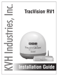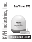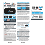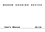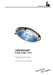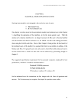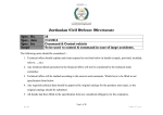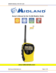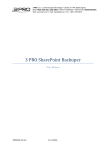
1
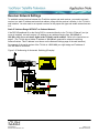
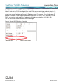
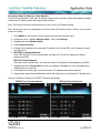
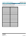
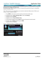
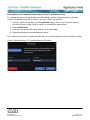
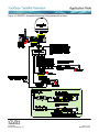
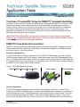
AppNote1401 Revised
12 September 2014
®
TracVision TV-series/RV1 Setup for DIRECTV Automatic Switching
TracVision TV-series and RV1 systems can automatically switch between DIRECTV’s 101W and 119W
satellites as necessary as you change channels on the master SWM-compatible receiver’s remote
control (you select which of your receivers is the master at the TV-Hub’s web interface or mobile app).
The antenna system communicates with the master receiver via the TV-Hub’s Ethernet port. This
application note explains how to set up this communications link with the SWM-compatible receivers.
Associated wiring diagrams begin on page 10.
IMPORTANT! The 119W satellite only carries local channels for certain regions of the country.
Check this list of locations that use 119W for locals. If your locals are carried on DIRECTV’s main
101W satellite, you do not need automatic switching.
DIRECTV Coax Network Connections
DIRECTV recently adopted coax networking technology, by which both satellite TV signals and network
communications data are carried by the coax cables. This simplifies installation, since Ethernet cables
don’t need to be run to all of the receivers.
Non-Genie Configurations
If a Genie DVR (HR44 or HR34) is not present on your DIRECTV SWM network, you need to install a
DECA with power supply and DC to RF adapter, collectively referred to as a DECA Broadband Kit (KVH
part no. 19-0860) and formerly called a Cinema Connection Kit. When connected to the SWM splitter and
the TV-Hub’s Ethernet port, either directly or via an onboard router, the DECA relays messages between
the DIRECTV coax network and the Ethernet network.
Figure 1: DECA Broadband Kit Contents
DECA (DIRECTV Ethernet Coaxial Adapter)
Power Supply
DC to RF Adapter
Genie Configurations
Full DECA Broadband functionality is built into Genie DVRs (HR44 or HR34). So if a Genie DVR is
present on your DIRECTV SWM network, no external DECA Broadband kit is required. Just connect the
Genie’s Ethernet port to the TV-Hub’s Ethernet port, either directly or via an onboard router. The Genie
DVR provides the link between the DIRECTV coax network and the Ethernet network. (If you cannot
easily connect the Genie DVR to the TV-Hub, you can use a DECA Broadband Kit for the Ethernet link.)
AppNote1401
© 2014 KVH Industries, Inc.
Page 1 of 11
9/12/2014
Additional Equipment for Older Receivers
In addition to the DECA Broadband Kit or a Genie DVR, you might need to connect an additional
device in-line between the individual receiver(s) and the SWM splitter, depending on the model.
H24, H25, and HR24 Models – No additional devices are needed
New receivers, such as these models, have built-in DECA functionality for coax networking. The
“Satellite In” port can handle both the satellite TV signal and network communications data.
H21, H22, H23, HR21, HR22, and HR23 Models
These receivers do not have built-in DECA functionality, but they have an Ethernet port for network
connectivity. An additional DECA (KVH part no. 19-0860) is required for each of these receivers to
support coax networking, supplying the satellite TV signal to the receiver’s “Satellite In” port and network
communications data to its Ethernet port. (If there are two of each port, use the “Satellite In 1” and
“Ethernet 1” ports.)
Note: Each DECA that you connect directly to a receiver is powered by the receiver. They do not require
the separate power supply included in the DECA Broadband Kit.
H20 Model
This receiver is not network-ready. It is only designed to receive a satellite TV signal via its “Satellite In”
port. Since both the satellite TV signal and network communications data are present on the coax cables,
a band stop filter (KVH part no. 19-0868) is required to block the network data to prevent potential
damage to the receiver. Be sure to connect all band stop filters before connecting the coax cables.
Since the H20 cannot communicate over the network, it cannot control satellite selection.
Figure 2: Band Stop Filter
Receiver Models
Additional Device Required
KVH Part No.
H24, H25, HR24
None
N/A
H21, H22, H23, HR21, HR22, HR23
DECA (included in DECA Broadband Kit)
19-0860
H20*
Band Stop Filter
19-0868
* Model HR20-100 requires additional devices. Contact KVH Technical Support for details.
AppNote1401
© 2014 KVH Industries, Inc.
Page 2 of 11
Revised: 9/12/2014
Receiver Network Settings
To establish communications between the TracVision system and each receiver, you need to set each
receiver to a static IP address and enter that address, along with the receiver’s location, in the TV-Hub’s
web interface. You also need to set up each receiver for the proper dish type and enable external access
to it.
Static IP Address Range WITHOUT an Onboard Network
If the DECA Broadband Kit or the Genie DVR is connected directly to the TV-Hub’s “Ethernet” port (no
router is installed), set each receiver’s IP address to any address ranging from 192.168.x.2 to
192.168.x.149, where x=1<last 2 digits in the TV-Hub’s serial number>. Refer to the instructions on
page 5. (The TV-Hub has a hidden IP address of 192.168.x.1 reserved for automatic switching
communications. This IP address is not shown on the Network Settings page of the web interface.)
For example, if the serial number of the TV-Hub is 140901484, you might assign an IP address of
192.168.184.2 to a receiver.
Figure 3: IP Addressing for Automatic Switching (Example)
AppNote1401
© 2014 KVH Industries, Inc.
Page 3 of 11
Revised: 9/12/2014
Static IP Address Range WITH an Onboard Network
If the TV-Hub and the DECA Broadband Kit or Genie DVR are connected to an onboard network (i.e.,
router), set each receiver to a static IP address that is outside the router’s DHCP range. (Refer to your
router’s user manual for details on finding its IP address range.) For example, if the router has an IP
address of 192.168.1.1 and assigns IP addresses ranging from 192.168.1.100 to 192.168.1.149 via
DHCP, you could set each receiver’s IP address to any address ranging from 192.168.1.150 to
192.168.1.254. Refer to the instructions on the next page.
Figure 4: Router DHCP Settings (Example)
AppNote1401
© 2014 KVH Industries, Inc.
Page 4 of 11
Revised: 9/12/2014
Assigning a Static IP Address to Each Receiver
Once you have identified a valid static IP address range for your receivers, follow these steps to assign a
unique static IP address within that range to each receiver.
Note: The receiver must be activated before you can access its IP address setting.
Note: These steps may vary, depending on receiver model and software version. Refer to your receiver’s
manual for details.
1. Press MENU on the receiver’s remote control to access the onscreen menu.
2. At the main menu, highlight Settings & Help. Then select Settings.
3. Highlight and select Network Setup.
4. Select Advanced Setup.
5. Change the IP address to the new static IP address. (On a Genie DVR, the IP address is called
the “Server IP”).
6. WITHOUT an Onboard Network
Enter “255.255.255.0” for the subnet mask, and enter the TV-Hub’s IP address for default
gateway and DNS.
WITH an Onboard Network
Enter the router’s subnet mask, and enter the router’s IP address for default gateway and DNS.
7. Highlight and select Connect Now to save your changes. Disregard any error messages about
missing Internet connectivity.
8. In the table on the next page, record the receiver’s IP address and location onboard.
9. Repeat these steps for each additional receiver. Be careful not to use the same IP address twice.
Figure 5: IP Address Setting on a DIRECTV Receiver (Examples)
WITHOUT an Onboard Network
AppNote1401
© 2014 KVH Industries, Inc.
WITH an Onboard Network
Page 5 of 11
Revised: 9/12/2014
Recording Each Receiver’s IP Address and Location
Use the table below to record the IP addresses and locations of all of your receivers. Later, you will need
to enter this information in the TV-Hub’s web interface.
IP Address
AppNote1401
© 2014 KVH Industries, Inc.
Location Onboard
Page 6 of 11
Revised: 9/12/2014
Allowing External Access on the Receiver(s)
Now that all of the IP addresses are entered, you need to set up each receiver to allow the TV-Hub to
communicate with it over the network.
Note: These steps may vary, depending on your receiver’s model and software version. Refer to your
receiver’s owner’s manual for details.
1. Press MENU on the receiver’s remote control to access the onscreen menu.
2. At the main menu, highlight Settings & Help. Then select Settings.
3. Highlight and select Whole-Home.
4. Highlight and select External Device.
5. Set External Access to Allow.
6. At the warning message, select OK.
Figure 6: External Access Setting on a DIRECTV Receiver
AppNote1401
© 2014 KVH Industries, Inc.
Page 7 of 11
Revised: 9/12/2014
Setting the Dish Type on the Receiver(s)
Be sure to set each SWM-compatible receiver to the proper dish type and switch type for compatibility
with the TracVision antenna.
Note: These steps may vary, depending on your receiver’s model and software version. Refer to your
receiver’s owner’s manual for details.
1. Press MENU on the receiver’s remote control to access the onscreen menu.
2. At the main menu, highlight Settings & Help. Then select Settings.
3. Highlight and select Satellite.
4. Highlight and select Repeat Satellite Setup.
5. At the warning message, press the Dash (-) button on the receiver’s remote control.
6. Set Dish Type to 3-LNB and Switch Type to SWM.
7. Highlight and select Continue.
Figure 7: Satellite Dish Setup on a DIRECTV Receiver
AppNote1401
© 2014 KVH Industries, Inc.
Page 8 of 11
Revised: 9/12/2014
Entering Receiver IP Addresses and Locations in the TV-Hub Web Interface
To complete the communications link between the receivers and the TracVision system, enter each
receiver’s IP address, along with its location, into the TV-Hub’s web interface.
1. At the TV-Hub’s web interface, go to the Autoswitch page. Refer to the TracVision system’s
Quick Start Guide or Help Center for details on accessing the web interface.
2. Select Add Receiver.
3. Enter the receiver’s location and IP address. Then select Save.
4. Repeat this procedure for each additional receiver.
Note: Entering the receivers’ locations will allow the user to easily identify them when selecting a master.
Figure 8: Receiver Setup in TV-Hub Web Interface (Example)
AppNote1401
© 2014 KVH Industries, Inc.
Page 9 of 11
Revised: 9/12/2014
Figure 9: DIRECTV Automatic Switching Configuration without a Genie
AppNote1401
© 2014 KVH Industries, Inc.
Page 10 of 11
Revised: 9/12/2014
Figure 10: DIRECTV Automatic Switching Configuration with a Genie
AppNote1401
© 2014 KVH Industries, Inc.
Page 11 of 11
Revised: 9/12/2014