Download CS-GSM Transceiver Kits - Bad Request
Transcript
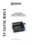
CS-GSM
Transceiver Kits
(inc. Fastrack Xtend Modules)
Instructions for Use with
Campbell Scientific
Dataloggers
Issued 2.7.12
Copyright © 2004-2012 Campbell Scientific Ltd.
CSL 131
Guarantee
This equipment is guaranteed against defects in materials and workmanship.
This guarantee applies for twelve months from date of delivery. We will
repair or replace products which prove to be defective during the guarantee
period provided they are returned to us prepaid. The guarantee will not apply
to:
•
Equipment which has been modified or altered in any way without the
written permission of Campbell Scientific
•
Batteries
•
Any product which has been subjected to misuse, neglect, acts of God or
damage in transit.
Campbell Scientific will return guaranteed equipment by surface carrier
prepaid. Campbell Scientific will not reimburse the claimant for costs incurred
in removing and/or reinstalling equipment. This guarantee and the Company’s
obligation thereunder is in lieu of all other guarantees, expressed or implied,
including those of suitability and fitness for a particular purpose. Campbell
Scientific is not liable for consequential damage.
Please inform us before returning equipment and obtain a Repair Reference
Number whether the repair is under guarantee or not. Please state the faults as
clearly as possible, and if the product is out of the guarantee period it should
be accompanied by a purchase order. Quotations for repairs can be given on
request. It is the policy of Campbell Scientific to protect the health of its
employees and provide a safe working environment, in support of this policy a
“Declaration of Hazardous Material and Decontamination” form will be
issued for completion.
When returning equipment, the Repair Reference Number must be clearly
marked on the outside of the package. Complete the “Declaration of
Hazardous Material and Decontamination” form and ensure a completed copy
is returned with your goods. Please note your Repair may not be processed if
you do not include a copy of this form and Campbell Scientific Ltd reserves
the right to return goods at the customers’ expense.
Note that goods sent air freight are subject to Customs clearance fees which
Campbell Scientific will charge to customers. In many cases, these charges are
greater than the cost of the repair.
Campbell Scientific Ltd,
Campbell Park, 80 Hathern Road,
Shepshed, Loughborough, LE12 9GX, UK
Tel: +44 (0) 1509 601141
Fax: +44 (0) 1509 601091
Email: [email protected]
www.campbellsci.co.uk
PLEASE READ FIRST
About this manual
Some useful conversion factors:
Area: 1 in2 (square inch) = 645 mm2
Length:
1 in. (inch) = 25.4 mm
1 ft (foot) = 304.8 mm
1 yard = 0.914 m
1 mile = 1.609 km
Mass:
1 oz. (ounce) = 28.35 g
1 lb (pound weight) = 0.454 kg
Pressure:
1 psi (lb/in2) = 68.95 mb
Volume:
1 UK pint = 568.3 ml
1 UK gallon = 4.546 litres
1 US gallon = 3.785 litres
Recycling information
At the end of this product’s life it should not be put in commercial or domestic refuse
but sent for recycling. Any batteries contained within the product or used during the
products life should be removed from the product and also be sent to an appropriate
recycling facility.
Campbell Scientific Ltd can advise on the recycling of the equipment and in some cases
arrange collection and the correct disposal of it, although charges may apply for some
items or territories.
For further advice or support, please contact Campbell Scientific Ltd, or your local agent.
Campbell Scientific Ltd, Campbell Park, 80 Hathern Road, Shepshed, Loughborough, LE12 9GX, UK
Tel: +44 (0) 1509 601141 Fax: +44 (0) 1509 601091
Email: [email protected]
www.campbellsci.co.uk
Contents
PDF viewers note: These page numbers refer to the printed version of this document. Use
the Adobe Acrobat® bookmarks tab for links to specific sections.
1. Introduction.................................................................. 1
2. Quick Start Guide ........................................................ 2
3. Using GSM Networks for Data Transfer .................... 3
3.1 Network Coverage .................................................................................... 4
3.2 Call Charges ............................................................................................. 4
4. Initial Fastrack Setup .................................................. 5
4.1 Configuring and Fitting the SIM .............................................................. 5
4.2 Connection to a Datalogger ...................................................................... 5
4.2.1 Connection to a CS I/O Port ........................................................... 6
4.2.2 Connection to an RS232 Port .......................................................... 6
4.3 Connecting Power..................................................................................... 7
4.4 Selecting and Connecting an Antenna ...................................................... 8
4.4.1 Antenna Supplied by Campbell Scientific ...................................... 9
5. Configuring the Fastrack for use with a
Datalogger................................................................ 10
5.1 Setup ....................................................................................................... 10
5.2 Configuration for the GSM Network ...................................................... 11
5.3 Base Station ............................................................................................ 12
5.3.1 Configuring a Desk-Top Modem as a Base Station ...................... 12
5.3.2 Configuring the Fastrack as a Base Station using Loggernet ....... 12
5.3.3 Extending the Default Time-Outs ................................................. 13
6. Preventing Fastrack Connection Problems ............ 14
7. Fault Finding .............................................................. 15
7.1 General.................................................................................................... 15
7.2 The Base Station Fails to Get a Response from the Datalogger ............. 16
7.3 I Get Errors When Using the Fastrack with Storage Modules ............... 16
Appendix A. Using the Fastrack with the PIN Security
Feature Enabled............................................................ A-1
A.1 Introduction......................................................................................... A-1
A.2 CRBasic Program Example ................................................................ A-1
A.3 CR10X Program Example .................................................................. A-3
i
Appendix B. Controlling the Power Supply to the
Fastrack Module ........................................................... B-1
B.1 Controlling the Power Consumption of the Fastrack ........................... B-1
B.1.1 CR10X Program Example ........................................................... B-2
Appendix C. Useful Configuration Commands for the
Fastrack ......................................................................... C-1
C.1
C.2
C.3
C.4
Signal Quality Checks.......................................................................... C-1
Network Registration Checks .............................................................. C-2
PIN Configuration ............................................................................... C-4
Changing the Wavecom operating frequency between EU/Rest
of world and US wavebands ............................................................... C-4
Appendix D. Using the Fastrack in Transparent
Mode .............................................................................. D-1
D.1 Introduction .........................................................................................D-1
D.2 Disabling the RLP Protocol .................................................................D-1
Appendix E. Resetting the Fastrack Module Under
Program Control ........................................................... E-1
E.1 Principle of Control .............................................................................. E-1
E.2 CRBasic Program Example .................................................................. E-1
E.3 CR10X Program Example.................................................................... E-2
Figures
1. Connecting the FASTRACK to a Datalogger ............................................ 6
2. Antenna Supplied by Campbell Scientific .................................................. 9
Tables
1. FASTRACK Power Supply Connections ................................................... 7
This is a blank page.
ii
Use of the CS-GSM digital transceiver
kits with Campbell Scientific Dataloggers
This manual provides the details of how to use the CS-GSM digital transceiver kits with
Campbell Scientific dataloggers. This version of the manual covers kits that use the Sierra
Wireless/Wavecom Fastrack Xtend GSM module as the communication device. Details in this
manual are specific to this model introduced in January 2011. If you have an older model i.e.
not the Xtend version please request an older version of this manual from Campbell Scientific.
Settings in this manual relate to using GSM as opposed to GPRS data collection, which is
supported in the CS-GPRS package.
1. Introduction
The CS-GSM kits use the Sierra Wireless/Wavecom Fastrack Xtend module that
is designed to allow transfer of data across a GSM (Global System for Mobile
communications) digital cellular phone network. The Fastrack is a GSM digital
transceiver; it can be thought of as a GSM ‘phone’ module without a handset, but
which has an extra interface to allow data devices to be connected. It has the
following features:
•
Standard RS232 serial port
•
Relatively low power consumption
•
Wide operating temperature range (-30°C to +75°C)
•
Can be used to collect data from a datalogger at a similar speed to a landbased 9600 baud modem in good reception areas
•
Closely emulates a standard ‘Hayes style’ telephone modem; suitable for
situations where the datalogger instigates a call back to a base station, e.g. for
alarm purposes
•
Compact package: 89x60x30mm (subject to change).
The CS-GSM kits include all the cables and antenna to allow easy use with
Campbell Scientific dataloggers
1
CS-GSM Digital Transceiver Kits
2. Quick Start Guide
If you purchased the standard CS-GSM kit you will have been supplied with a
Fastrack module, SC-WMI logger interface plus SC12 cable, mounting bracket
and an aerial. The CS-GSM232 kit includes a special RS232 cable instead of the
SC-WMI interface and SC12. For either kit the module is preconfigured so that it
should work “out of the box”.
This section of the manual gives brief instructions and pointers to the rest of the
manual to enable you to setup the system and get running quickly.
1.
NOTE
2
Make sure you have a data enabled SIM with the security PIN disabled. You
should have been notified of a telephone number specifically for data use
with the SIM. Referring to the picture below insert the SIM into the SIM
socket on the Fastrack unit as shown, paying particular attention to the
orientation of the SIM and fully slide the locking catch across to lock the
SIM in place and allow it to be read.
The locking catch slides across and the SIM card must then be
pushed in to allow the card to be ejected. To reinsert the card push
it in, where it will be retained, then slide the catch across. If the
catch is not moved across, the card will not be read and the status
LED will remain on, in the disconnected state.
2.
Connect the SC-WMI to the Fastrack and the datalogger as shown in figure 1
(section 4.2.1) of this manual. (If you are not using the SC-WMI and have
purchased the RS232 version of the CS-GSM package, then connect the
Fastrack to the RS232 port of the datalogger.)
3.
Install the aerial supplied as high as possible on your mounting structure and
away from any vertical metal poles. Route the cable into the enclosure and
connect it to the aerial socket on the Fastrack unit – this may involve use of a
coaxial adaptor (supplied if needed).
4.
Connect the power supply to the Fastrack unit, by connecting the red/black
power lead either directly to the outlet of the power supply, if powering the
device continuously or to a suitable power switch – see section 4.3 below. It
Using with Campbell Scientific Dataloggers
is best to connect the power as close as possible to the battery rather than to
terminals on the datalogger if possible.
5.
Turn on the power to the datalogger and Fastrack module. The status LED
on the end of the package, near the SIM socket should come on continuously
initially. After a period of about 15 seconds the LED will start to flash
briefly every 2-3 seconds. When the LED starts to flash it indicates that the
module has signed onto the phone network successfully.
6.
Start-up your PC and run PC400, Loggernet or your chosen communications
program. Set up a phone or TAPI connection to the datalogger, following the
instructions for your software package to do this. Enter the data phone
number assigned to your SIM as the phone number of the datalogger to be
called.
7.
Apply the setup setting and then connect to the datalogger. You should find
the PC connects to the datalogger and the displayed datalogger time then
starts to update showing you have a working system. If this does not happen
please read the rest of this manual in more detail.
3. Using GSM Networks for Data Transfer
GSM networks are based on international standards and are widespread
throughout the world – see the web site www.gsm.org. Theoretically a GSM
phone can be used anywhere in the world if it is within range of a GSM network
of the same frequency. For voice communications this theory almost works in
practice, except that many airtime providers (the company you pay for use of the
phone) limit the geographical range of most phones, and some do not have
agreements with distant providers.
For data transmission, most networks support the SMS (Short Message System).
This is not very practical for collecting large volumes of data, but can be useful for
sending alarm messages – see Technical Note 33 for more details of using SMS.
(Please note that the Fastrack defaults to Text format SMS messages and as the
message centre is normally preset in the SIM it is not necessary to pre-configure
the module as described in the technical note.)
Larger networks support connections where an open data connection is formed
through the network. If this is supported, you may choose to connect to a GSM
data-phone either via a landline modem (landline to GSM) or by using a second
GSM phone in your office (GSM to GSM).
Before considering the use of the Fastrack in your application, check with your
local GSM network company that they support the use of the Fastrack for the
‘non-transparent’ mode of data transmission, at 9600 baud. Check also that they
provide suitable routes to allow you to communicate with it, such as access via
land-line modems – this is called asynchronous connectivity.
The current design of the Fastrack will operate by default on GSM900 (900 MHz)
or GSM1800 (1800 MHz) networks. If you wish to use the modem on US GSM
frequencies, please refer to Appendix C. Whenever possible a GSM900 network
should be used as 1800 MHz networks (which includes the Orange and T-Mobile
networks in the UK) are designed with smaller cells because of the reduced
propagation range of higher frequency radio waves. Therefore GSM1800 phones
have a shorter range, which can cause more problems in areas of dubious signal
coverage.
3
CS-GSM Digital Transceiver Kits
NOTE
The Fastrack supplied is set up for standard GSM data transfer.
Please contact Campbell Scientific for more information on use for
GPRS data transfer.
3.1 Network Coverage
One of the main advantages of using a cellphone network is being able to set up a
communications link to a datalogger virtually anywhere without installing land or
telephone lines. However, this only applies if a suitable GSM network covers your
installation site.
Within the UK the coverage of GSM networks is good in most areas. However,
coverage in remote areas can still be quite poor and is not likely to improve, as it
offers little commercial advantage to the network companies. Unless coverage is
known to be good at the proposed site, we strongly recommended that you test the
coverage using a standard GSM handset (on the same network as the Fastrack is to
be used) to measure the exact signal strength.
NOTE
Even areas shown as having good coverage on network maps can
have ‘holes’ due to local interference or other technical reasons, and
so site testing is recommended.
In areas of normal signal strength the Fastrack can be used with a small, low cost
antenna (as supplied in the CS-GSM package). However, if the signal strength is
marginal it may be possible to improve reception using a raised and/or a higher
gain antenna. Poor quality reception will normally lead to breaks in
communication or result in the PC software having to make multiple requests to
ensure uncorrupted data is collected. This will not usually lead to data loss or
corruption, but may result in longer calls and thus higher call charges.
The network maintainer will be able to offer advice on coverage problems.
Campbell Scientific can also offer further advice on suitable antennae to suit the
application.
3.2 Call Charges
Call charges on cellular-based phones are usually much higher than landline based
systems and can therefore be quite high for a long-term data collection campaign.
Careful choice of the tariffs available can result in a considerable reduction in the
total bill. Obviously the tariff chosen should allow use of the phone for data
transmission. Some very low cost packages are limited to voice only, but some
companies offer cheap data-only tariffs as well. Limiting calls to off-peak and
weekend periods can also result in major cost savings.
One major factor, which can determine call costs, is the method used to connect to
the remote Fastrack. If you call the Fastrack from a landline phone modem, you
will normally pay your landline phone company the same (high) cost as calling a
voice cellphone. This is independent of your agreement with the cellphone airtime
provider. In many cases it may be cheaper to buy an extra Fastrack or other data
enabled GSM phone for your base station, thus avoiding the use of the land-based
phone line altogether. This could also enable you to benefit from the special tariffs
for data-only transmission provided by the airtime companies. Also, the set-up
time from a GSM to GSM module is usually much lower and the overall call will
thus be shorter and thus cost less.
4
Using with Campbell Scientific Dataloggers
If you cannot use a base station GSM module, lower cost calls may also be
possible by programming the datalogger to call back to the land-line phone base
station, as the special airtime rates will normally apply to such calls too.
Where many calls have to be made in quick succession ISDN digital landlines can
be used with a digital terminal adaptor in the calling PC. If correctly supported
and set-up for the phone account by the network operator, the connection time can
be reduced to one or two seconds which can substantially reduce the call bill. This
is done by setting the system to communicate in a digital fashion throughout (UDI
mode). Please contact Campbell Scientific Ltd for further advice on this matter.
NOTE
Where a datalogger is only receiving incoming calls it is often
possible to use a “Pay as you go” SIM card to avoid extra rental
charges.
You need to check with the SIM provider that they
support data transmission on PAYG and that the SIM is not disabled
after some period, if it makes no outgoing calls.
4. Initial Fastrack Setup
4.1 Configuring and Fitting the SIM
Before the Fastrack can be used or tested, it must be fitted with a ‘SIM’
(Subscriber Identification Module) that enables it for use on a specific cellular
telephone network in a particular frequency band. For some networks, e.g. 02 in
the U.K, you may need to specify the mode of data transfer. If this is required,
request it to work in ‘non-transparent mode’ at 9600 baud. This is the default
setting for most networks. The Fastrack will also work in transparent mode but
this is more susceptible to errors and call breakdown so should only be used if the
network does not support non-transparent mode (see Appendix D for more
information). Your airtime provider will normally supply you with an extra phone
number for the SIM specifically for data use.
If possible, ensure that the SIM is configured so that it does not require a Personal
Identification Number (PIN) security code to be entered after the module is
powered up. The PIN can most easily be disabled by inserting it into a separate,
hand-held standard GSM phone and following the instructions contained in the
phone manual. If a separate phone is not available, please contact Campbell
Scientific for details of how to disable the PIN code for use with the Fastrack. If
this is not possible, or if your airtime provider only allows operation with a PIN
enabled, please refer to Appendix A.
NOTE
Many SIM suppliers send the SIM with the PIN enabled and set to a
default PIN number. Check the documentation that came with your
SIM.
The SIM card is installed in the Fastrack in the slot at the aerial end of the case.
The SIM is pushed into the centre of the slot with the end with the notch on the
corner first. The gold contacts should be on the same side as the blue Fastrack
label. The card should be pushed in and then released. It should stay fully inserted
if correctly aligned. (To remove, push the card in and then release to make it pop
out). Once the card is pushed in, a small black slide switch has to be slid across
the end of the card to prevent accidental removal. This switch also enables reading
of the card, so it must be slid across until it clicks otherwise the unit will not
register on the GSM network.
5
CS-GSM Digital Transceiver Kits
4.2 Connection to a Datalogger
The Fastrack can either be connected to the CS I/O port of dataloggers that have
this port, using the standard SC-GSM kit or directly to the RS232 port of the
datalogger if it has one using the RS232 cable provided as part of the CS-GSM232
kit.
If your datalogger has both an RS232 and CS I/O port you may still wish to use
the standard SC-GSM kit as it frees the RS232 port allowing a local PC to be
connected to be used or for connection to a sensor. Communicating via the CS
I/O port requires less power than the RS232 port (by ~10 mA) although the
quiescent consumption is much the same. The datalogger is also able to terminate
calls a few seconds quicker via the SC-WMI which may reduce the caller’s phone
bill to some extent.
4.2.1 Connection to a CS I/O Port
To enable normal operation of all Campbell Scientific peripherals that might share
the 9-way serial I/O port on the datalogger (e.g. Storage Modules), it is necessary
to use an interface between the datalogger and the Fastrack.
The Campbell Scientific SC-WMI interface provides a simple, very low power
interface for connecting the Fastrack module to the CS I/O port on Campbell
Scientific dataloggers. This unit is provided as part of the current CS-GSM
package. The quiescent current consumption of the SC-WMI is typically less than
100 µamps and it uses less than 3 mA when communications are in progress.
There is no use configuration of this device. It is simply connected between the
datalogger CS I/O port and the Fastrack module as shown below in Figure 1.
NOTE
If you want to use the Fastrack to communicate with storage
modules connected to the datalogger, you need to use the latest
release of the Loggernet software package for guaranteed reliable
communication.
SC-WMI
SC12 cable
Fastrack Modem
9-pin
Connect to 9-pin
‘CSI’ socket on
datalogger
Connect to 15-pin
socket on Fastrack
Diagram Not to Scale
Figure 1 Connecting the Fastrack to a Datalogger
4.2.2 Connection to an RS232 Port
If using a CR23X, CR800, CR1000, CR3000 or CR5000 datalogger, an alternative
connection is possible using the RS232 port, if this is free. The CR200 only has an
RS232 port so this is the only option.
6
Using with Campbell Scientific Dataloggers
The cable required for the direct connection to a datalogger serial port is supplied
as part of the CS-GSM232 kit. The 9-pin connector plugs in the datalogger
RS232 port and the 15-way connector directly into the Fastrack module.
NOTE
The cable supplied for use with the Fastrack Xtend is different from
that supplied with older modules. The cable has additional control
wires that are not used in standard Campbell installations. These
are insulated and cut back can covered with insulation at the free
end of the cable.
4.3 Connecting Power
The Fastrack module requires a power supply capable of supplying 5-32V DC, at
an average current of up to 500mA, with short peak currents of 2.5A (at 5.5 V
supply). Fastrack recommend that a 2A slow acting, fuse is inserted in the positive
rail of the supply, to minimise damage in the event of a failure. This fuse is fitted
in the power cable supplied. Additionally, Campbell Scientific power supplies
include a slow response solid-state automatic resetting fuse. The normal colour
scheme for wiring is RED for positive and BLACK for negative.
If the Fastrack is to be powered from the same supply as the datalogger, ensure
that the power connections for the Fastrack are made as close as possible to the
battery outputs. This will prevent the Fastrack causing voltage drops and noise on
the supply to the datalogger.
The quiescent power consumption of the Fastrack plus the SC-WMI is typically
around 10 mA, once the unit automatically shuts down at the end of a call.
Having the unit powered all the time ensures unhindered access at any time by
remote users and also avoids complications of having the datalogger program
include code to control the power.
For intermediate power supply situations it is possible to switch the Fastrack into a
mode where it partly shuts-down to a lower power state between calls, saving an
extra 6 mA, to ~4 mA. However, this requires code in the datalogger program to
control this as the Fastrack has to receive commands to make this happen after
power-up or reset. Please refer to Appendix B.
For very low power installations turning the power off may be essential though.
To do this it is possible to control the power supply to the Fastrack unit by using a
solid state relay, such as the PSW12 power switch or, if free, to use the power
switch built into the wiring panel of some dataloggers. See Appendix B for
example programs where the datalogger controls power to the Fastrack. Table 1.
shows the wiring from the PSW12 power switch to the datalogger.
Table 1 Fastrack Power Supply Connections via a PSW12 switch
Fastrack Cable Colour
Red (positive supply)
Black (negative supply)
Yellow (power control)
Connection
+12V
G
Control Port (or +12V for testing)
N.B. These colours and connections only apply to the cable supplied by
Campbell Scientific Ltd.
7
CS-GSM Digital Transceiver Kits
NOTE
In the case of CR10X dataloggers, only the power switch in wiring
panels fitted with green terminal blocks is suitable.
4.4 Selecting and Connecting an Antenna
When selecting an antenna, please note the following points:
• Make sure the antenna used covers the frequency you intend to use the
Fastrack on, i.e. does the antenna cover 900 or 1800 MHz, or both (dual band).
• Low cost, ¼- or ½-wave antennae are adequate for most applications where
signal coverage is good. It is important to realise that most low cost antennae
designed for vehicle mounting require a flat, metal sheet to form a ground
plane at the base of the antenna to achieve the specified gain figure and to
ensure proper impedance matching. As an approximate rule the ground plane
should have a radius equal to or greater than the height of the radiator.
• Slightly higher priced co-linear, ‘marine’-grade antennae do not require such a
ground plane and can be more easily pole or cross-arm mounted.
• In areas of poor signal coverage a directional, high-gain ‘Yagi’ antenna can be
considered, but this requires knowledge of where the cell base stations are
situated in order to enable proper alignment.
• Raising the antenna is often the most effective way of getting better signal
reception. However, if long cables are required to achieve this, use low-loss
extension cables that do not have the significant signal loss of low cost cables.
Long cables are a particular problem when operating at 1800MHz.
• Like most cellular-based systems, the Fastrack varies its transmitter power to
ensure good communications with the remote cell station. Using a cheaper,
low-gain, antenna may result in a significant increase in power consumption in
areas of poor signal coverage.
• If the antenna is placed near the top of a mast it may be vulnerable to lightning
damage. If lightning is common at the installation site, additional lightning
protection may be required to protect the Fastrack – please contact Campbell
Scientific for further advice.
CAUTION
Using an antenna that is installed incorrectly, or with faulty wiring,
can lead to premature failure of the transmitter output of the
Fastrack.
Install the antenna so that the radiator is positioned away from other vertical metal
structures. It should also be at a distance from any sensors so that it does not either
physically or electrically interfere with the sensor readings. If the Fastrack is
connected to a PC (see below) it is possible to check the received signal strength
using the AT+CSQ command (see Appendix C or the Fastrack manual for further
details). This can be used to find the optimum antenna position. You should aim to
get the highest signal strength (as close to 31) as possible. For reasonable
communications you need a minimum level of approximately 10 when operating
in non-transparent mode. Be sure that the module is configured to talk only to the
network operator you intend to use when doing this (see the AT+COPS
command).
8
Using with Campbell Scientific Dataloggers
CAUTION
Many antenna have bodies that are connected to the coaxial
cable screen. It is therefore essential to ensure the correct
polarity is maintained through the cabling system to avoid the
possibility of shorting the transmitter output of the Fastrack to
the power supply ground via the lightning protection cables
and mounting structure.
4.4.1 Antenna Supplied by Campbell Scientific
Campbell Scientific can supply various antennas, if required; including a ‘lowcost’ antenna (see Figure 2, below). This is supplied as part of the standard CSGSM package.
In areas of high signal strength, the low-cost antenna will be suitable for almost all
applications, either at 900 or 1800 MHz. The antenna, as supplied ‘off the shelf’,
is fitted with a connector which will either directly fit the Fastrack transceiver
aerial socket or plug into an adaptor that will be supplied. When the antenna is
supplied as part of a weather station or other complete installation, Campbell
Scientific may replace the original connector with a compatible connector before
the system is tested.
In a field installation it is recommended that the cable length between the antenna
and the transceiver is kept as short as possible to reduce the signal loss in the
cable, although, as mentioned above, it is often more advantageous to mount the
antenna higher. In some applications the cable will need to be shortened, and so a
new connector can be installed onto the cable at this time by cutting off the surplus
cable, together with the original connector, and fitting a new connector. Ensure
that all connections are well made, and the connector is secured using a crimping
tool or pliers. The connector which connects to the module is only suitable for use
in dry environments and so must be protected from direct exposure to water and
precipitation.
Figure 2 ‘Low-cost’ dual-band antenna supplied by Campbell Scientific
9
CS-GSM Digital Transceiver Kits
The antenna is supplied with a pole mounting adaptor, a `V’ bolt, allowing it to be
fitted to 30-54 mm diameter vertical tubing. If you need to mount antenna onto a
smaller diameter pole, insert some hard packing material between the pole and
bracket. Alternatively, without the adaptor, it can be screwed to a suitable flat
vertical surface. The design of the antenna means that no ground plane is
required, thus allowing more flexibility in mounting. Avoid mounting the antenna
close to other vertical metal structures or on flat metal surfaces.
Higher gain YAGI style antennas are available from Campbell Scientific to
special order. These can help with reception in remote areas or where reception is
poor due to obstacles, but can take some experimentation to find the best
orientation to get the optimum reception.
5. Configuring the Fastrack for use with a Datalogger
If bought as part of a CS-GSM package the Fastrack will be preconfigured by
Campbell Scientific to work out of the box so no configuration is normally
necessary.
If you have obtained the Fastrack as a separate item, you must configure it and
store the settings in its non-volatile memory to ensure proper operation with
Campbell Scientific dataloggers.
The Fastrack Xtend modem is fitted with a USB interface and supplied with
suitable USB cable. The USB interface can be used for checking operation of the
modem or using it as a base station modem. However, as it has settings
independent to those for the RS232 port it cannot be used to fully reconfigure the
modem for use with a datalogger. To use it, if your version of Windows does not
automatically recognise the USB device when plugged in you will need to install
the relevant driver. This can be obtained by visiting the website
www.sierrawireless.com , going to the downloads section registering, and looking
for the USB driver under the product information for the AirLink Fastrack Xtend
EDGE FXT009.
Once installed an additional virtual com port will appear in the list of available
com ports in programs such as the Device configuration program or
Hyperterminal. The com port does not indicate it is the Xtend module , e.g. it
might be “COM6” or similar. You can check if this is the module by unplugging
it and seeing if the port disappears.
Once identified you can use the virtual port as if the modem is connected to a
standard serial port.
For full configuration of the RS232 port you can obtain a convertor cable between
the 15 pin socket on the module and a standard 9-pin connector suitable to plug in
the serial port of a PC. These are available from Campbell Scientific Ltd and
called a wavecom programming cable. In an emergency it is also possible to send
commands from the datalogger to the attached module, but this requires complex
programming. With the CR800, CR1000 or CR3000 dataloggers it is also
possible to `talk-through’ from one serial port to the modem connected on another.
When the modem is offline you can send configuration commands to the modem
via this route – see the datalogger manual and the description of terminal mode.
If the Fastrack has been purchased with a cable for plugging into a datalogger
RS232 port a null modem cable will be required to convert from the 9 way plug at
the end of this cable to the PC serial port. Any terminal software used with this
combination should be set to “No hardware handshaking”.
10
Using with Campbell Scientific Dataloggers
5.1 Setup
To enable configuration:
1. Connect the Fastrack to a PC as described above.
2. Make sure the antenna is fitted before powering up the Fastrack otherwise it
may be damaged.
3. Connect the Fastrack to a suitable power supply, ensuring if a power switch is
fitted, that the power control line is held high to force the Fastrack to remain
switched on permanently during configuration.
4. Select a suitable terminal emulation package (e.g. HyperTerminal, included
with Microsoft Windows 95/98/NT/XP or the `unknown’ device setting in
Campbell Scientific’s Device Configuration program) to communicate with
the Fastrack in order to configure it. If the module has not been configured
before you need to set the baud rate of the terminal emulator to match the
factory default of the Fastrack. Earlier models, e.g. the 1203 default to 9600
baud. More recent models default to 115200 baud. Xtend modems setup by
Campbell Scientific for GPRS use are also set to 115 kbaud. Set the other
RS232 parameters to 8 bits, 1 stop bit, 1 start bit and no parity with the
relevant PC com port. The terminal type emulation is not important. For
Hyperterminal set the handshaking to off.
5. To check communications with the Fastrack type AT&F and press ENTER. The
Fastrack should respond on the following line with OK. This resets the
Fastrack to the default settings. If you get no response to this command or
other characters appearing as you type it is likely the module is not set to the
factory default baud rate. You need to try different baud rates, starting at
9600 baud, until the correct response is seen. Please remember that some
terminal emulators, such as HyperTerminal require you to click on the
disconnect button and then reconnect before the changes to communications
baud rate come into effect.
6. You then need to fix the baud rate, normally to 9600 baud for use with all
Campbell Scientific dataloggers for GSM dialup use (CSD). To change the
setting type AT+IPR=9600;&W This will change the communications speed
and write the setting to non-volatile memory.
CAUTION
If you get the response ‘ERROR’ or ‘4’ after entering the
above AT commands, please ensure that the terminal
software is set up to communicate via the COM port to which
the Fastrack is connected, and not with any internal modem
which may be fitted in the computer.
5.2 Configuration for the GSM Network
The Fastrack must be configured to work on the particular network for which its
SIM is valid. These settings will probably have been pre-set by the supplier of
your SIM. If not, refer to details in Appendix C or the Fastrack operator’s manual
with reference to the AT+CREG and AT+COPS commands. If you are using the
modem in the USA or some other countries it may be necessary to change the
modems waveband. See Appendix C, section C.4 for details.
A summary of the configuration procedure is:
1. Make sure the module has been fully reset and then configured to run at 9600
baud as detailed above.
2. Issue the required commands (see below) either individually or in
combination.
11
CS-GSM Digital Transceiver Kits
3. Issue the final AT&W command to store the set-up in non-volatile memory.
The following commands are required to change the settings from the factory
defaults (please refer to the Fastrack manuals for full details). Enter the command
and then press the return key. Wait for a response before proceeding with the next
command.
AT&F
Reset to factory default settings.
ATX0
Basic connect messages only.
(AT&S0
Force DSR high - required only for use with the SC32A or
RAD modems.)
ATS0=1
Set the Fastrack to auto-answer incoming calls.
AT+IFC=0,0
Handshaking off.
AT+WIND=0
Turn off advanced result codes.
AT+CICB=0
Force incoming calls to data mode if no bearer declared.
AT+WASR=1
Mode which turns off the serial port when DTR is low.
AT+WOPEN=0 Turn off any AT-OPEN applications that may be included in
the Fastrak operating system.
AT+WRST=1,
“025:00”
Automatically reset the modem every 25 hours (unless reset in
another way).
ATV0
Numeric result codes – the Fastrack will not respond with
‘OK’ to this or following commands; instead it returns ‘0’
(zero) at the start of the current line.
AT&W
Saves all of the above settings in non-volatile memory.
To validate all settings are correct, issue the AT&V command to display many of
the settings on the screen. Make sure the settings are all shown in ‘Active Profile’.
CAUTION
If you get the response ‘ERROR’ or ‘4’ after entering the
above AT commands, please ensure that the terminal
software is set up to communicate via the COM port to which
the Fastrack is connected, and not with any internal modem
which may be fitted in the computer.
Also ensure that the Fastrack has a valid SIM installed with
the PIN security function unlocked or disabled.
5.3 Base Station
Either a standard desktop modem or the Fastrack itself can be configured as a base
station. Details are given in the following sections.
5.3.1 Configuring a Desk-Top Modem as a Base Station
You can use most desktop landline and even cellphone modems to connect to a
remote Fastrack module. The modem should be setup as if calling a remote
landline modem. The baud rate for connection should be set to 9600 minimum.
The modem can be configured to connect either via the TAPI or Phone modem
settings (TAPI being the preferred option if you have installed the modem into
your Windows environment.)
12
Using with Campbell Scientific Dataloggers
NOTE
While Campbell Scientific Ltd may be able to give some advice as
to the best settings to use for common modems, the connection of
the landline modem to a cellular network is specific to the cellular
network being used. Problems establishing the connections are often
not related to the fact that a Fastrack or datalogger are connected at
the remote end of the connection, but are caused by compatibility
issues of the PC modem with the network. Please also contact your
cellular network support team for advice on any problems that you
might encounter.
5.3.2 Configuring the Fastrack as a Base Station using Loggernet
Sierra Wireless do not provide specific drivers for the Fastrack unit. Instead they
recommend that you follow the normal Windows procedure for installing a TAPI
modem and select the modem type “Standard 9600 bps” or “Standard 19200 bps”.
Check that Windows finds the modem and attaches it to the correct COM port.
For this to work you must make sure the baud rate of the module has been setup
previously to match the modem type selected. Thereafter you can use the module
to call-out using the TAPI interface.
You can also use the Phone modem option in Loggernet, using the default modem
type, with the baud rate set to 9600 baud. This option is preferred if additional
modem settings are required (see below) or if the Fastrack is often unplugged
from the PC, as the TAPI interface expects to find the module connected at all
times.
NOTE
Before use it is also necessary to reconfigure the modem back to its
factory default settings using a terminal emulator and issuing the
AT&F, AT+1FC=2,2, then the AT&W commands.
5.3.3 Extending the Default Time-Outs
When using either a landline base modem or a Fastrack as the base, it is sometimes
necessary to extend the time both the PC and the base modem will wait before
timing out an attempted connection to a remote modem. Many modems have a
default timeout of 30 seconds which may not be long enough for connection over
busy or distant networks. Adding “S7=45” to the end of the modem initialisation
string sets the timeout at 45 seconds and Loggernet will increase its own timeouts
to suit. Normally you are allowed to increase this setting up to 60 (seconds) if a call
is seen to take such a long time to connect. Setting too long a delay may, however,
slow down the retry sequence in the event of a failed connection.
To add this setting, use the Phone modem option in Loggernet where you can edit
the modem initialisation string in the setup screen. You cannot amend this setting
for a TAPI interface in a way that Loggernet can also detect.
Campbell Scientific communications software includes other time-outs which are
used to check for hung communications links. These are set to be quite short for
land-based modems, as the response to any command sent from the PC should be
almost instantaneous. A link to a remote Fastrack normally passes through several
nodes of a digital data network, all of which can add delays. Usually these delays
are less than one second and so have no effect on the communications process.
However, on a long distance call or busy network, the built in time-out delay for
the PC software may need to be extended.
In Loggernet or PC400W, a station-specific delay can be added by increasing the
time in the ‘Extra response time’ box shown on the datalogger hardware set-up
13
CS-GSM Digital Transceiver Kits
screen. This delay is entered in seconds. Loggernet has a default, built-in, delay of
~2 seconds, which is adequate for use with the Fastrack in most cases. On busy
networks, or with poor communication links, a value of 3 or even 4 may be
required, to allow the error correction process to function.
Where a Fastrack is used as the base station modem, it is advisable to increase
these delays even more by perhaps another 1-2 seconds, if communications are
proving to be unreliable.
NOTE
Entering too large a delay can slow down the entire communications
process, and so an optimal value should be determined by trial and
error.
6. Preventing Fastrack Connection Problems
There is a very small chance that the Fastrack could crash or simply lose
registration with the phone network. Crashes may be the result of electrical spikes
on the power supply or local electrical storms. If the Fastrack is powered
continuously, such a crash will often prevent it answering an incoming call again
until it has been reset.
GSM phone modules can also be deregistered from the cellphone network. This
means that they are effectively logged off the network preventing new incoming
calls. The reasons this can happen are that the network may miss the regular "I am
here" messages that the Fastrack transmits every few seconds or, in some cases,
the network will timeout the registration due to inactivity. The exact algorithm
used to decide whether to deregister a phone varies from network to network.
Problems are more likely where the connection is marginal or where the local cell
is congested.
To help overcome these problems, the datalogger can be programmed to either
reset the Fastrack by sending it commands (see Appendix E) or to shut down the
Fastrack at regular intervals using a power switch as described in Appendix B.
This will save power, but also ensures that the Fastrack is reset into a known state
and to make it re-register itself on the network. To be sure that the Fastrack resets
properly, it must be turned off for at least 10 seconds. How often the Fastrack is
turned off will depend on the normal calling schedule, considerations of power
consumption and of how long you could afford to lose communication with the
Fastrack if it did go offline.
When turning the power off to the modem it is advisable to avoid cutting the
power when the modem is online. The program examples in Appendix B check if
the modem is online before turning off the power. You should also avoid
scheduling calls to the logger when it is due to power off. If possible the
AT+CFUN=0 command should also be sent to the modem before cutting the
power to let the modem cleanly deregister from the network and shutdown its
radio module (also shown in the example in Appendix B). If the modem is not
cleanly shutdown there may be a delay of some minutes before the network will
allow access to the modem again (and in GPRS mode, prevent modem from
establishing a PPP connection).
CAUTION
14
Repeatedly cutting the power off to the modem without taking
these precautions can cause a corruption to the modem
settings or firmware that may need to be reset at the factory.
Using with Campbell Scientific Dataloggers
NOTE
The CS-GSM modules are currently set to automatically reset every
25 hours unless the modem is reset before this timeout by a power
cycle or by being sent a reset command. As the modem will go
offline for some tens of seconds when reset it is best to issue a reset
under program control at known times (see Section 6).
7. Fault Finding
7.1 General
Before placing the Fastrack out in the field it is important to check that it is
properly registered on a GSM network. To do this, connect it to a power supply
and turn on any power switch, if used, by connecting the power control line to 5V
or 12V. After power has been applied, the small LED in the case should come on
continuously initially. Within 30 seconds the LED should switch to start to flash
briefly every 2 seconds or so indicating that the unit has registered itself
successfully with a GSM network. As a second check connect it to a PC and,
using a terminal emulation program, instruct it to dial a valid telephone number,
e.g. ATD01509601091 <ENTER>. If the Fastrack does not cause the remote phone
to ring but instead immediately responds with a result code 3 (‘no carrier
detected’) it is likely that:
• It has not been registered properly on a GSM network — see the Wavecom
Fastrack user’s manual and notes above.
NOTE
If the Fastrack has definitely been registered on the GSM network,
check that the registration is for ‘non-transparent use’. Also check it is
enabled for GSM Data (CSD) at 9600 baud – not just GPRS data. For
GSM data connections you need to be able to connect from analogue
landlines – the SIM provider will normally give you a second phone
number to dial it on.
or
• It is not fitted with a SIM, the SIM locking switch is not in place or the SIM is
not enabled (check with your provider)
or
• The SIM is programmed to require a PIN to be entered every time it is turned
on. This is often the case with newly supplied SIMs. We strongly
recommend that this feature is disabled; this is best done using a GSM phone
(please refer to your SIM provider for more information).
NOTE
Please refer to Appendix A if you can only access a network where
use of a PIN is a legal obligation with the airtime provider.
• The power supply is inadequate, e.g. it cannot supply the high surge currents
during transmission. (See Section 4.3.)
Once communication is established with a datalogger via the Fastrack, it is
essential to monitor how error-free the communications link is, Loggernet
generates log files which indicate the number of attempts required to retrieve good
data (‘retries’). While the chances of getting bad data stored to disk are very small
(because of the error checking protocols used) the speed at which data is collected
can fall markedly if the link is very noisy. This will lead to much higher phone
charges. If many retries are recorded it is worth checking the signal strength,
studying the antenna position and the likely causes of interference.
15
CS-GSM Digital Transceiver Kits
If you still encounter problems it is also worth checking the firmware version of
the Fastrack module. Campbell Scientific has validated use with units with
firmware revision: “R7.42” (checked using instruction ATI3). While later
software revisions will probably be backwards compatible, older software may not
work so well. Please contact your supplier for an upgrade if necessary.
7.2 The Base Station Fails to Get a Response from the Datalogger
Check the following points:
•
Is the Fastrack configured to ignore hardware handshaking (see Section 6.2)
•
Have you ensured that your base station modem setup includes commands to
switch off flow control from the base station?
•
Are you powering the Fastrack on and off periodically?
•
If so, the datalogger program which is controlling the power of the Fastrack is
either wrong, or is not running (perhaps due to a low battery voltage).
•
the number you are dialling is the voice number for the SIM rather than the
data number - if you get "deadline" when the Fastrack is on or an
"answerphone" service when it is turned off this is almost certainly the
problem.
•
If you manually dial the number with a phone and hear a buzzing noise rather
than modem negotiation tones (beep and whistles) the SIM is configured to
accept incoming digital (UDI) calls only - contact the SIM supplier.
7.3 I Get Errors When Using the Fastrack with Storage Modules
This was a problem with some versions of PC208W. You are advised to upgrade
to LoggerNet to resolve this problem.
16
Appendix A. Using the Fastrack with the
PIN Security Feature Enabled
It is possible to use the Fastrack with Campbell Scientific dataloggers with the Fastrack’s PIN
(Personal Identification Number) feature enabled. However, this has the following disadvantages:
•
If the Fastrack loses power momentarily, it will not answer further calls until the datalogger
sends the PIN again as part of the normal program sequence. If the datalogger is programmed
to send the PIN only once (leaving the Fastrack permanently switched on), a datalogger reset
would be needed to re-enable the system. If a regular turn on / turn off sequence is used (as
described under ‘Controlling the Power Consumption of the Fastrack’ in Appendix B), the
system will be disabled until the next sequence occurs.
•
If the Fastrack fails to unlock the PIN code, for whatever reason, three times in a row, the SIM
card will be permanently locked. This will require you to contact your airtime service provider
to provide an ‘unlock’ code for the SIM.
A1. Introduction
To operate with the Fastrack’s PIN feature enabled, the datalogger must transmit the
command to send the PIN to the Fastrack after turning on the power. For CRBasic
dataloggers this is simply done by using serial commands to send the PIN code after
the modem is turned on, see the example below. For Edlog dataloggers this is done
using Instruction P97 ‘Initiate Telecommunications’ using the ‘Generic Modem’
option. This option has only been added in recent releases of the CR510, CR10X and
CR23X operating systems – from versions 1.06, 1.13 and 1.10 (and later) respectively.
If you have one of these dataloggers with an older operating system, you should
contact Campbell Scientific to arrange an upgrade.
Users of older dataloggers, e.g. the 21X, CR10 or CR7, should contact Campbell
Scientific to obtain a copy of a manual written for early versions of the M20T which
describes an alternative, but more complicated, way of sending PIN codes using special
cables and Instruction P98, ‘Send Character’.
A2. CRBasic Program Example
This example can be used on the CR800 series. CR1000 and CR3000 dataloggers. It
uses the standard CRBasic serialopen, serialout and serialclose commands to send out
configuration commands to the modem. The example shows using a slow sequence to
sending the command to unlock the PIN immediately after turning on the modem.
'CR1000 Series Datalogger
'Example program showing how to turn on/off a GSM modem and disable the PIN code
'Also includes the correct sequence to shutdown the modem cleanly before turning
'off the power.
'The modem control is done in a slow sequence to avoid interference with measurements
'Declare Public Variables
'Example:
Public PTemp, batt_volt
A-1
CS-GSM Digital Transceiver Kit
'Main Program
BeginProg
'Normal measurements in the main scan here
Scan (1,Sec,0,0)
PanelTemp (PTemp,250)
Battery (Batt_volt)
'......etc
NextScan
'------------------------------------------------------------------'Modem control slow sequence - can be cut and paste as self-contained
'Set this constant to match the port the modem is connected to
Const Modemport=COMME
Const Modembaud = 9600 'Change to match modem baud rate
SlowSequence
'Run once a minute so can have one min resolution of timing
Scan (1,Min,3,0)
'Every hour, in this example, turn on the modem
If TimeIntoInterval (0,60,Min) Then
'Set port 1 to 1 (ON) (use writeio as in slowsequence)
WriteIO (&B00000001,1)
Delay(1,2,sec) 'Allow 2 seconds for the modem to power on
SerialOpen (Modemport,modembaud,0,0,100)
'Send the command to unlock the pin code (PIN=601141 in this case)
'Allow one retry
SerialOut (Modemport,"AT+CPIN=601141"+CHR(13),"0"+CHR(13),1,100)
'Optionally send the command to allow low power shutdown (Wavecom specific)
SerialOut (Modemport,"AT+W32K=1"+CHR(13),"0"+CHR(13),1,100)
SerialClose(Modemport)
EndIf
'10 minutes later turn the modem off
If TimeIntoInterval (10,60,Min) Then
SerialOpen (Modemport,modembaud,0,0,100)
'Send the command to log off the network and shutdown cleanly
SerialOut (Modemport,"AT+CFUN=0"+CHR(13),"0"+CHR(13),1,300)
SerialClose(Modemport)
'Set port 1 to 0 (LOW) (use writeio as in slowsequence)
Delay(1,2,sec) 'Allow 2 seconds for the modem to shutdown
WriteIO (&B00000001,0)
EndIf
NextScan
EndProg
A-2
Appendix A. Using the Fastrack with the PIN Security Feature Enabled
A3. CR10X Program Example
Using Instruction P97 with the generic modem option does not require any special
cabling or set-up. It is possible that the generic modem option may not be fully
documented in your datalogger manual, but you should be able to find some
information in the help system of Edlog for Windows. To gain a full understanding of
the general mode of operation of P97 please refer to the examples in the datalogger
manual.
For the purpose of unlocking a PIN code, P97 is used with the datalogger ID set to 0,
which causes the instruction simply to send and check the responses to commands sent
to the ‘modem’, without then proceeding to make a call.
Below is an example program which turns on the Fastrack and sends the PIN so that
the Fastrack can receive calls.
This program, for the CR10X, shows how to transmit the PIN command
(AT+CPIN=nnnnnnn, where nnnnnnn is the PIN). The program includes a delay
after turning the Fastrack on, before calling P97. This is required because it takes
approximately two seconds for the Fastrack to power-up.
;{CR10X}
; An example program which shows how to turn the Fastrack on and send
; a PIN code using Instruction P97 with the Generic Modem option.
; The power to the Fastrack is controlled by Port 1
; Please note that no measurement or data storage instructions are
; shown - this is an example of Fastrack power control only.
*Table 1 Program
01: 10
Execution Interval (seconds)
;Other measurement instructions here
;At the start of every hour, say, turn on the Fastrack
1:
1:
2:
3:
If time is (P92)
0
Minutes (Seconds --) into a
60
Interval (same units as above)
30
Then Do
;Turn on the power (Fastrack power controlled by C1 in this case)
;Add extra code if low battery voltages are likely (see above)
2: Do (P86)
1: 41
Set Port 1 High
; Now set flag 1 low to enable P97 in Generic Modem mode to send the PIN
3: Do (P86)
1: 21
Set Flag 1 Low
4:
End (P95)
; Now immediately call P97 to send the PIN unlock sequence
; This needs to start straight away after the TC35 is turned on so that it does
; not get locked out by the logger going into communications mode when the ;Fastrack
sends its wakeup 0 <CR> (meaning OK)
A-3
CS-GSM Digital Transceiver Kit
5: Initiate Telecommunications (P97)
1: 72
Generic Modem/9600 Baud
2: 1
Disabled when User Flag 1 is High
3: 20
Seconds Call Time Limit ; More than enough time to send
command
4: 30
5: 1
Seconds Before Fast Retry ; just in case
Fast Retries ;try just once more
6: 9999
Minutes before Slow Retry ; don't try for a long time
otherwise
7: 3
8: 0000
Failures Loc [ BadPINcnt ]
Call-back ID ; set to 0 indicates not a proper call
6:
1:
2:
3:
4:
5:
6:
Extended
68
50
87
50
-69
17
Parameters 4 Digit (P68)
Option ;D wait
Option ; 5 seconds for the Fastrack to power up
Option ;Set wait delay to wait for up to
Option ;5 sec for any response, aborting if not received
Option ;E - transmit with echo
Option ;17 chars - change for length of PIN code
7: 65
Option ;A
8: 84
Option ;T
7: Extended Parameters 4 Digit (P68)
1: 43
Option ;+
2: 67
Option ;C
3: 80
Option ;P
4: 73
Option ;I
5: 78
Option ;N
6: 61
Option ;=
7: 54
Option ;6
8: 54
Option ;6 This example uses a PIN code of 66011411
8:
1:
2:
3:
4:
5:
6:
7:
8:
Extended
48
49
49
52
49
49
13
82
Parameters 4 Digit (P68)
Option ;0
Option ;1
Option ;1
Option ;4
Option ;1
Option ;1
Option ;CR
Option ;R to wait for response
9:
1:
2:
3:
4:
5:
6:
7:
8:
Extended
2
48
13
0000
0000
0000
0000
0000
Parameters 4 Digit (P68)
Option ;2 characters
Option ;0
Option ;<CR>
Option
Option
Option
Option
Option
; Now the instructions to turn it off
; At 10 past the hour set flag 2 to indicate to turn off
10: If time is (P92)
1: 10
Minutes (Seconds --) into a
2: 60
Interval (same units as above)
3: 12
Set Flag 2 High
;If the logger is not communicating, i.e. ‘Modem is Off’ (ME line low)
;then if flag 2 is high
A-4
Appendix A. Using the Fastrack with the PIN Security Feature Enabled
11: If Flag/Port (P91)
1: 50
Do if Modem is Off
2: 30
Then Do
12: If Flag/Port (P91)
1: 12
Do if Flag 2 is High
2: 30
Then Do
;Turn off the Fastrack
13: Do (P86)
1: 51
Set Port 1 Low
;Set flag 2 low
14:
Do (P86)
1: 22
Set Flag 2 Low
;and disable the PIN code transmission via P97, just in case it is still trying
15: Do (P86)
1: 11
Set Flag 1 High
16:
End (P95)
17:
End (P95)
*Table 2 Program
02: 0
Execution Interval (seconds)
*
End Program
-Input Locations1 Temp_C
1 0 0
2 Call_Fail 1 0 0
3 BadPINcnt 1 0 1
4 _________ 0 0 0
5 _________ 0 0 0
6 _________ 0 0 0
7 _________ 0 0 0
8 _________ 0 0 0
9 _________ 0 0 0
10 _________ 0 0 0
11 _________ 0 0 0
12 _________ 0 0 0
13 _________ 0 0 0
14 _________ 0 0 0
15 _________ 0 0 0
16 _________ 0 0 0
17 _________ 0 0 0
18 _________ 0 0 0
19 _________ 0 0 0
20 _________ 0 0 0
21 _________ 0 0 0
22 _________ 0 0 0
23 _________ 0 0 0
24 _________ 0 0 0
25 _________ 0 0 0
26 _________ 0 0 0
27 _________ 0 0 0
28 _________ 0 0 0
-Program Security0000
A-5
CS-GSM Digital Transceiver Kit
0000
0000
-Mode 4-Final Storage Area 20
-CR10X ID0
-CR10X Power Up-
Other applications may require the PIN code to be sent prior to a callback call or prior
to sending an SMS message (see Technical Note 33 ‘Sending SMS Messages using
GSM modems’). For those applications which also use Instruction 97, the AT+CPIN
can either be sent first (as above) followed by a second call of P97 to force the callback
(once the first call is successful) or the AT+CPIN command can be incorporated in the
normal dial string. Please contact Campbell Scientific if further advice on these
techniques is needed.
If a Fastrack with the PIN feature enabled is to be used with a PC as the base station,
the CPIN=nnnnnn command can be included at the end of the Modem Initialisation
string.
NOTEThe Fastrack will respond with a code indicating an error condition if the PIN is
sent more than once after it has been powered up. This will not prevent the
system dialling correctly.
A-6
Appendix B. Controlling the Power
Supply to the Fastrack Module
This Appendix describes how the datalogger can be used to control the power supply to a
Fastrack module to minimise power consumption.
B.1 Controlling the Power Consumption of the
Fastrack
The power consumption of the Fastrack system is much lower than many other
cellphones, being typically 10mA while waiting for calls and <200mA when online. As an option a power switch can be used with the Fastrack, which allows the
datalogger to turn off the power supplied to the Fastrack and thereby minimise
power use. However, the Fastrack will not answer any incoming calls when in this
state.
The first thing to consider when designing the power supply for your Fastrack
system is the possibility of only switching on the Fastrack for, say, one hour per
day, during which time a base station can be synchronised to collect data. The
lowest overall power consumption can be obtained by making the datalogger turn
the power on only when it makes outgoing calls. However, this would prevent you
calling the datalogger at will from a base station to check its status or to load a
new program.
Once the total time per day that the datalogger will be turned on in its different
power states is determined, a daily power consumption can be estimated and the
power supply designed accordingly. For most typical remote applications a
PS100E and a medium-sized solar panel will suffice. Please refer to Technical
Note 12 (Calculating Power Consumption and Solar Panel Size) for further details.
To allow the Fastrack to receive calls, program the datalogger to set the relevant
control port high to turn the Fastrack on. The Fastrack will not answer an
incoming call when the power control line is low. Control is normally done using
the datalogger instruction (If Time) with the command option to set the port high
(after an additional check on the battery status) or low at specific times.
The time for which the Fastrack is switched on needs to be long enough to allow
an incoming call to be started, data collection made and the call completed. The
dataloggers allow an extra refinement to this sequence, which allows the ‘on-time’
to be reduced further. This is because it is possible to monitor if the comm port is
still active. The program can then be written to turn off the Fastrack only if the
datalogger is not communicating. The following sequence could be included in a
program to turn on the Fastrack for 5 minutes every hour, but only turn it off if a
call is not in progress.
B-1
CS-GSM Digital Transceiver Kit
B1.1 CRBasic Program Example of Power Control
This example can be used on the CR800 series, CR1000 and CR3000 dataloggers.
It uses the standard CRBasic serialopen, serialout and serialclose commands to
send out configuration commands to the modem. The example shows using a slow
sequence to turn on and then turn off the modem after 5 minutes. When it comes
to turn off the modem it sets a flag. If communications are still active the modem
is not turned off unless a full 15 minutes have expired since it was turned on.
This example also shows how to turn on the “W32K” lower power mode after the
mode is turned on and how to log off the network before power is turned off
(using AT+CFUN=0).
'CR1000 Series Datalogger
'Example program showing how to turn on/off a GSM modem
'This example only turns on the modem for 5 minutes, but extends the time on for up
'to 15 minutes if the com port is active when it is time to shutdown.
'Also includes the correct sequence to shutdown the modem cleanly before turning
'off the power.
'The modem control is done in a slow sequence to avoid interference with measurements
'Declare Public Variables
'Example:
Public PTemp, batt_volt
'Main Program
BeginProg
'Normal measurements in the main scan here
Scan (1,Sec,0,0)
PanelTemp (PTemp,250)
Battery (Batt_volt)
'......etc
NextScan
'------------------------------------------------------------------'Modem control slow sequence - can be cut and pasted as self-contained
'Set this constant to match the port the modem is connected to
Const Modemport=COMRS232
Const Modembaud = 115200 'Change to match modem baud rate
Public timetogooff As Boolean
SlowSequence
'Run once a minute so can have one minute resolution of timing
Scan (1,Min,3,0)
'Every hour, in this example, turn on the modem
If TimeIntoInterval (0,60,Min) Then
'Set port 1 to 1 (ON) (use writeio as in slowsequence)
WriteIO (&B00000001,1)
Delay(1,2,sec) 'Allow 2 seconds for the modem to power on
SerialOpen (Modemport,Modembaud,0,0,100)
'Send the command to allow low power shutdown
'between calls (Wavecom specific)
SerialOut (Modemport,"AT+W32K=1"+CHR(13),"0"+CHR(13),1,100)
SerialClose(Modemport)
EndIf
'5 minutes later turn the modem off if it is not online
'First set a variable to indicate the 5 min time has passed
If TimeIntoInterval (5,60,Min) Then timetogooff=true
'If time to go off also check we are offline OR that 15 mins has not passed
'i.e. shutdown at 15 mins anyway
B-2
Appendix B. Controlling the Fastrack Power Supply
'NOTE: edit the commactive variable to match the serial port being used for the
modem
If (timetogooff AND (NOT status.commactiveRS232)) OR TimeIntoInterval(15,60,min)
Then
SerialOpen (Modemport,Modembaud,0,0,100)
'Send the command to log off the network and shutdown cleanly, wait up to 3 sec.
'First send the +++ sequence to get the modem in command mode - in case online
SerialOut (Modemport,"+++","0"+CHR(13),1,150)
SerialOut (Modemport,"AT+CFUN=0"+CHR(13),"0"+CHR(13),1,300)
`Delay to allow deregistration
delay (1,2,sec)
SerialClose(Modemport)
'Set port 1 to 0 (LOW) (use writeio as in slowsequence)
WriteIO (&B00000001,0)
timetogooff=false
EndIf
'-------------------------------------------------------------------NextScan
EndProg
B-3
CS-GSM Digital Transceiver Kit
B.1.2 CR10X Program Example
;Fastrack power control example code for the CR10X
;Port 1 is the control port used to control the switch ON/OFF
;Flag 1 is used to indicate the Fastrack should be turned off
;when any current call has ended.
;On
;IF
1:
1:
2:
3:
the hour turn the Fastrack on
the battery voltage is good (see text below)
If time is (P92)
0000
Minutes (Seconds --) into a
60
Interval (same units as above)
30
Then Do
;Measure the logger battery voltage
2: Batt Voltage (P10)
1: 1
Loc [ BattV
]
;and if it is > than 11.5 V turn on the Fastrack
3: If (X<=>F) (P89)
1: 1
X Loc [ BattV
]
2: 3
>=
3: 11.5
F
4: 41
Set Port 1 High
4:
End (P95)
;At 5 past every hour set Flag 1 to indicate to turn off the
;Fastrack when any current call is finished.
5: If time is (P92)
1: 5
Minutes (Seconds --) into a
2: 60
Interval (same units as above)
3: 11
Set Flag 1 High
;If
6:
1:
2:
Flag 1 is set AND
If Flag/Port (P91)
11
Do if Flag 1 is High
30
Then Do
;the datalogger is not communicating (ME off) THEN
7: If Flag/Port (P91)
1: 50
Do if Modem is Off
2: 30
Then Do
;Turn off the power to the Fastrack
8: Do (P86)
1: 51
Set Port 1 Low
;and set low flag 1, to allow it to be turned on next time
9: Do (P86)
1: 21
Set Flag 1 Low
10:
11:
B-4
End (P95)
End (P95)
Appendix B. Controlling the Fastrack Power Supply
CAUTION
If power is limited and the turn-on time has to be kept very
short, it is critical to ensure that the PC and the datalogger
clocks are not allowed to drift apart, otherwise the PC may try
to call when the Fastrack is turned off. Clock synchronisation
can be achieved automatically, during data collection. Please
refer to the PC software manual for details on how to do this.
The Fastrack can also be used with instruction P97 (Initiate Telecommunications)
to make an outgoing call, either to return data to a remote computer or in the event
of an alarm. Instruction 97 is normally controlled by a program flag (referred to as
the Interrupt Disable Flag when programming P97) which is set low to make P97
initiate communications and call out. The process of setting this flag is normally
controlled by some program control logic before P97 is executed.
To ensure that the Fastrack is powered on for the outgoing call, an extra P91
instruction should be included before P97 to set the power control port high if the
interrupt disable flag has been set low. P97 will automatically set the flag high at
the end of a successful call, which the P91 will detect at the next scan and turn the
Fastrack off.
It is always best to design a power supply that has plenty of spare capacity to cope
with the power demands of the entire measurement system. If the power supply is
inadequate or faulty and the battery voltage is likely to drop to very low levels you
need to add extra code, as shown above to ensure the Fastrack is not turned on
when the battery voltage is low. In particular it should be disabled before the level
where the logger is likely to shutdown (below 9.6 V for the CR510/10X, higher
voltages for the CR23X or CR5000 - see their manuals).
If the voltage falls below this level while the Fastrack is already turned on, since
the datalogger program will stop running, there will be no mechanism to turn the
power off. This will cause the battery to discharge sooner rather than later. If
using 12V lead acid batteries, a threshold of 11.5 Volts is advised, below which
the Fastrack should not be turned on, as below this level the majority of the
capacity of the battery will have been used.
B-5
Appendix C. Useful Configuration
Commands for the Fastrack
This section gives details of some of the useful test commands that can be used during setup of
the Fastrack. Further details can be found in the Fastrack technical manuals.
General details referring to the telecommunications industry can be found at the European
Telecommunications Standards Institute (ETSI) web site at www.etsi.org.
C.1 Signal Quality Checks
AT+CSQ
Signal Quality
Test command
AT+CSQ=?
Response
+CSQ: (list of supported <rssi>s), (list of supported <ber>) OK
Parameter
See execute command
Response
TA returns received signal strength indication <rssi> and channel bit
error rate <ber> from the ME.
+CSQ: <rssi>, <ber> OK
Parameter
<rssi> :
0: -113 dBm or less
1: -111 dBm
30: -109 to –53 dBm
31: -51dBm or greater
99: not known or not detectable
<ber> : 0…7: as RXQUAL values in the table GSM 05.08
99: not known or not detectable
Execute command
AT+CSQ
C-1
CS-GSM Digital Transceiver Kit
C.2 Network Registration Checks
AT+COPS
Operator selection
Test command
AT+COPS=?
Response
TA returns a list of quadruplets, each representing an operator present in
the network. Any of the formats may be unavailable and should then be
an empty field. The list of operators will be in the following order: home
network, networks referenced in SIM, and other networks.
+COPS: [list of supported (<stat>), long alphanumeric <oper>,, numeric
<oper>)s][,,(list of supported <mode>s), (list of supported <format>s)]
OK
Parameter
See set command
Response
TA returns the current mode and the currently selected operator. If no
operator is selected,<format> and <oper> are omitted.
+COPS : <mode>[, <format>[, <oper>]]
OK
Parameter
See set command
Response
TA forces an attempt to select and register the GSM network operator. If
the selected operator is not available, no other operator will be selected
(except <mode>=4). The selected operator name format will apply to
further read command (+COPS?) also.
OK
Parameter
<stat>
0
unknown
1
operator available
0
operator current
1
operator forbidden
Read command
AT+COPS?
Set command
AT+COPS=
<mode>
[, <format>[, <oper>]]
<mode>
0: automatic (default value)
1: manual
2: deregistration ; ME will be unregistered until <mode>=0 or 1 is
selected.
3: set only <format> (for read command AT+COPS?)
4: manual / automatic (<oper> shall be present), if manual selection
fails, automatic mode is entered.
<format>: format of <oper> field
<format>
0: long alphanumeric format <oper>
1: short alphanumeric format <oper>
2: numeric <oper> (default value) <stat>: status of <oper>
<stat>
0: unknown
1: available
2: current
3: forbidden
<oper>: operator identifier (MCC/MNC in numeric format only for
operator selection)
C-2
Appendix C. Useful Configuration Commands
AT+CREG
Network registration
Test command
AT+CREG=?
Response
+CREG: list of supported <n>s OK
Parameter
See set command
Response
+CREG : <mode>, <stat> [ ,<lac>,<ci> ] for AT+CREG? Command
only
Read command
AT+CREG?
Set command
AT+CREG=[<n>]
Response
TA controls the presentation of an unsolicited result code
+CREG:<stat> when <n>=1 and there is a change in the ME network
registration status or code +CREG:
<stat>[,<lac>,<ci>] when <n>=2 and there is a change of network
cell.
OK
Parameter
<mode>
0: Disable network registration unsolicited result code (default)
1: Enable network registration code result code +CREG : <stat>
2: Enable network registration and location information unsolicited
result
code +CREG: <stat>,<lac>,<ci> if there is a change of network cell.
<stat>
0: not registered, ME is not currently searching for a new operator.
1: registered, home network.
2: not registered, ME currently searching for a new operator to register
to.
3: registration denied.
4: unknown.
5: registered, roaming.
<lac>: string type; two byte location area code in hexadecimal format
(e.g. “00C3” equals 195 in decimal).
<ci>: string type; two byte cell ID in hexadecimal format.
C-3
CS-GSM Digital Transceiver Kit
C.3 PIN Configuration
AT+CPIN
Enter PIN
Test command
AT+CPIN=?
Response
OK
Read command
AT+CPIN?
Response
TA returns an alphanumeric string indicating whether some password is
required or not.
+CPIN: <code> OK
If error is related to ME functionality:
+CME ERROR: <err>
Parameter
<code>
READY
no further entry needed
SIM PIN
ME is waiting for SIM PIN
SIM PUK
ME is waiting for SIM PUK
PH_SIM PIN ME is waiting for phone to SIM card
(antitheft)
PH_SIM PUK ME is waiting for SIM PUK (antitheft)
SIM PIN2
PIN2, e.g. for editing the FDN book, possible
only if preceding command was
acknowledged with +CME ERROR:17
SIM PUK2
possible only if preceding command was
acknowledged with error +CME ERROR:18
Response
TA stores a password which is necessary before it can be operated (SIM
PIN, SIM PUK, PH-SIM PIN, etc.). If the PIN is entered twice, the TA will
automatically repeat the PIN. If no PIN request is pending, no action is
taken and an error message, +CME ERROR is returned to TE.
If the PIN required is SIM PUK or SIM PUK2, the second PIN is required.
This second PIN, <newpin>, is used to replace the old PIN in the SIM.
OK
If error is related to ME functionality:
+CME ERROR: <err>
Parameter
<pin>
password (string type) does not need any
quotes. e.g. AT+CPIN=9515
<new pin>
if the PIN required is SIM PUK or SIM PUK2:
new password
Set command
AT+CPIN=<pin>
[, <newpin>]
C.4 Changing the operating frequency between
EU/Rest of world and US wavebands
In Europe and much of the rest of the world GSM communications happens either
in the 900 or 1800 MHz band (check with your local service provider). In the US
and some other countries the 850/1900 MHz bands are used. To switch to
alternative bands the modem must be connected to a PC and a command issued to
change the setup.
C-4
Appendix C. Useful Configuration Commands
To switch between EU/US band(s) for the FASTRACK, use a communication
software such as a HyperTerminal, then enter AT+WMBS=<band>,0
command.
The table below gives the commands for various band(s) selection:
AT+WMBS Band Selection
AT+WMBS=0,0
Select mono band mode 850MHz.
AT+WMBS=1,0
Select mono band mode extended 900MHz
AT+WMBS=2,0
Select mono band mode 1800MHz
AT+WMBS=3,0
Select mono band mode 1900MHz
AT+WMBS=4,0
Select dual band mode 850/1900MHz
AT+WMBS=5,0
Select dual band mode extended 900MHz/1800MHz*
AT+WMBS=6,0
Select dual band mode extended 900MHz/1900MHz
*The default setting in Europe.
After issuing the command the Fastrack module will have to be reset, by power
cycling the module to change to the new specified band(s). The setting is stored in
non-volatile memory automatically.
To check the Band(s) Selection
To check the band selection for the FASTRACK Supreme, use a communication
software such as HyperTerminal, then enter AT+WMBS? command.
The table below gives the main responses returned:
AT+WMBS Responses
+WMBS: 0,x Mono band mode 850MHz is selected
+WMBS: 1,x Mono band mode extended 900MHz is selected
+WMBS: 2,x Mono band mode 1800MHz is selected
+WMBS: 3,x Mono band mode 1900MHz is selected
+WMBS: 4,x Dual band mode 850/1900MHz are selected
+WMBS: 5,x Dual band mode extended 900MHz/1800MHz are selected
+WMBS: 6,x Dual band mode extended 900MHz/1900MHz are selected
C-5
Appendix D. Using the Fastrack in
Transparent Mode
It is possible to use the FASTRACK in transparent mode, when the default non-transparent
(RLP) mode is not supported by the cellular phone network or is incompatible with the
FASTRACK.
D.1 Introduction
The FASTRACK software includes an advanced error correction protocol known
as RLP, which is specially designed for RF links. This protocol is now used in one
form or another by most GSM data units but the FASTRACK implementation of
RLP may not be compatible with all GSM networks and some networks do not
support this mode at all.
NOTE
If you find that the FASTRACK does not work on the network
and suspect that it may be due to the RLP protocol, you must
check carefully with your own network provider to see if the
FASTRACK implementation of the protocol is known to work
correctly on their network.
The transparent mode relies on Loggernet/PC400W to correct any communication
errors. On poor quality lines the PC software will often drop the call and redial
when it sees a certain level of errors. (The non-transparent mode is less prone to
doing this.) For successful and fast communication a signal strength (as reported
by AT+CSQ – see Appendix C) of 18 or above is recommended for transparent
mode. The non-transparent mode will operate at signal levels down to as low as
10.
D.2 Disabling the RLP Protocol
If you wish to use the FASTRACK in transparent mode, do the following:
1. Get your SIM card in the FASTRACK enabled for transparent mode. In some
cases you may have to call your airtime provider to do this, (e.g. UK Cellnet
where you will be allocated a new number for this mode) while others (such as
UK Vodafone) need no configuration on the network and will switch
automatically depending on the FASTRACK configuration.
2. Re-enter the setup string as shown in Section 5.3 of this manual, but also enter
the AT+CBST command as AT+CBST=7,0,0 (where the last digit, 0,
switches the unit to transparent mode).
3. Save the settings using the AT&W command as normal.
D-1
Appendix E. Resetting the Fastrack
Module Under Program Control
This Appendix describes how the datalogger can be used to send commands to the Fastrack to
reset the module and also enable the lowest power mode which still allows incoming calls.
E.1 Principle of Control
To reset the Fastrack and change its mode of operation it can be sent commands
by the datalogger by embedding commands within a datalogger program. The
commands are identical to those that could be typed into a terminal emulator.
To reset the modem the command AT+CFUN=1<CR> is send. This attempts to
disconnect the modem from the network, fully resets the GSM module to a power
up state and then reconnects it to the network. This entire process can take up to
30 seconds, although the module will accept non-network related commands
within a few seconds of receiving the reset command.
In addition the example below turns off the automatic resetting mode, which
negates a setting used, in the past by CS, with some older modules that reset the
modem every 24 hours. (That mode is not now recommended by many networks
as it does not cleanly log off the network.) Clearly if the logger is controlling the
reset process the automatic process is redundant.
In addition the command AT+W32K=1 is sent after the reset to tell the module to
shut down to its lowest power state at the end of each call. This command has to
be reissued after the modem is reset under software or power control.
E.2 CRBasic Program Example
This example can be used on the CR800 series, CR1000 and CR3000 dataloggers.
It uses the standard CRBasic serialopen, serialout and serialclose commands to
send out configuration commands to the modem. The example shows using a slow
sequence to reset the modem every 12 hours, using the command AT+CFUN=1.
This example also shows how to disable any automatic reset and turn on the
“W32K” lower power mode after the modem is reset.
'CR1000 Series Datalogger
'Example program showing how to regularly reset the GSM modem
'The modem control is done in a slow sequence to avoid interference with measurements
'Declare Public Variables
'Example:
Public PTemp, batt_volt
'Main Program
BeginProg
'Normal measurements in the main scan here
Scan (1,Sec,0,0)
PanelTemp (PTemp,250)
Battery (Batt_volt)
'......etc
NextScan
E-1
CS-GSM Digital Transceiver Kit
'------------------------------------------------------------------'Modem control slow sequence - can be cut and pasted as self-contained
'Set this constant to match the port the modem is connected to
Const Modemport=COMRS232
Const Modembaud = 115200 'Change to match modem baud rate
SlowSequence
'Run once a minute so can have one minute resolution of timing
Scan (1,Min,3,0)
'Every 12 hours, in this example and only if we are not communicating
If TimeIntoInterval (0,12,hr) AND (NOT status.commactiveRS232) Then
SerialOpen (Modemport,Modembaud,0,0,100)
'First send the +++ sequence to get the modem in command mode
SerialOut (Modemport,"+++","0"+CHR(13),1,150)
'Send the command to reset the modem the connection wait up to 5 sec
SerialOut (Modemport,"AT+CFUN=1"+CHR(13),"0"+CHR(13),1,500)
Delay(1,2,sec) 'Wait another 2 sec just to make sure the reset is complete
'Send the command to turn off auto-reset, just in case
SerialOut (Modemport,"AT+WRSET=0"+CHR(13),"0"+CHR(13),1,100)
'Re-enable the low power clock mode
SerialOut (Modemport,"AT+W32K=1"+CHR(13),"0"+CHR(13),1,100)
SerialClose(Modemport)
EndIf
NextScan
'-------------------------------------------------------------------EndProg
E.3 CR10X Program Example
;{CR10X}
;Program example showing how to reset the Fastrack once per
;day and also how to reset the low power mode
;Instruction 97 is used to send out the reset commands
*Table 1 Program
01: 10
Execution Interval (seconds)
;As an example includes a simple measurement and data storage
;example
1: Batt Voltage (P10)
1: 1
Loc [ Batt
2:
1:
2:
3:
]
If time is (P92)
0
Minutes (Seconds --) into a
1
Interval (same units as above)
10
Set Output Flag High (Flag 0)
3: Real Time (P77)
1: 110
Day,Hour/Minute (midnight = 0000)
4: Sample (P70)
1: 1
Reps
2: 1
Loc [ Batt
E-2
]
Appendix E. Resetting the Fastrack Under Program Control
;In this example Table 2 is only used to control sending of
;the reset commands to the attached Fastrack unit
*Table 2 Program
02: 60
Execution Interval (seconds)
; At one minute to midnight set flag 8 low to force the
; module to be reset
; Note this will also happen immediately after the programmed
; is loaded to as flag 8 will be low then.
1: If time is (P92)
1: 1439
Minutes (Seconds --) into a
2: 1440
Interval (same units as above)
3: 28
Set Flag 8 Low
;Use P97 to send out the commands
2: Initiate Telecommunications (P97)
1: 72
Generic Modem/9600 Baud
2: 8
Disabled when User Flag 8 is High
3: 60
Seconds Call Time Limit
4: 0
Seconds Before Fast Attempts
5: 0
Fast Attempts
6: 0
Minutes Before Slow Attempts
7: 3
Failures Loc [ GSMError ]
8: 0000
Call-Back ID
;The commands below are sent blindly without
;checking the response from the modem.
;This is done for simplicity and to ensure the logger does
;not get stuck repeating instruction.
;First send the AT+CFUN=1 command to reset the module
3: Extended Parameters (P63)
1: 68
Option ; Delay to allow SC-WMI to power on
2: 10
Option ;1 second
3: 84
Option ;Transmit
4: 10
Option ;10 characters
5: 65
Option ;A
6: 84
Option ;T
7: 43
Option ;+
8: 67
Option ;C
;Wait for 2 secs to allow the module to get in a state to
;receive further commands
4: Extended Parameters (P63)
1: 70
Option ;F
2: 85
Option ;U
3: 78
Option ;N
4: 61
Option ;=
5: 49
Option ;1
6: 13
Option ;CR
7: 68
Option ;D for delay
8: 20
Option ;2 secs to allow to start up
;Now send out the command to disable the auto-reset
;There are some extra CR to fill up the P63
E-3
CS-GSM Digital Transceiver Kit
5:
1:
2:
3:
4:
5:
6:
7:
8:
Extended
84
12
65
84
43
87
82
83
Parameters (P63)
Option ;Transmit
Option ;12 Characters
Option ;A
Option ;T
Option ;+
Option ;W
Option ;R
Option ;S
6:
1:
2:
3:
4:
5:
6:
7:
8:
Extended
84
61
48
13
13
13
68
1
Parameters (P63)
Option ;T
Option ;=
Option ;0
Option ;CR
Option ;CR
Option ;CR
Option ;D for delay
Option ;0.1 sec to allow acceptance
;Now send the command to turn on the low power shutdown
7: Extended Parameters (P63)
1: 84
Option ;Transmit
2: 10
Option ;10 Characters
3: 65
Option ;A
4: 84
Option ;T
5: 43
Option ;+
6: 87
Option ;W
7: 51
Option ;3
8: 50
Option ;2
8:
1:
2:
3:
4:
5:
6:
7:
8:
Extended
75
61
49
13
68
10
0
0
Parameters (P63)
Option ;K
Option ;=
Option ;1
Option ;CR
Option ;D for Delay
Option ;1 sec to allow to complete
Option ;
Option ;
*Table 3 Subroutines
End Program
E-4
CAMPBELL SCIENTIFIC COMPANIES
Campbell Scientific, Inc. (CSI)
815 West 1800 North
Logan, Utah 84321
UNITED STATES
www.campbellsci.com • [email protected]
Campbell Scientific Africa Pty. Ltd. (CSAf)
PO Box 2450
Somerset West 7129
SOUTH AFRICA
www.csafrica.co.za • [email protected]
Campbell Scientific Australia Pty. Ltd. (CSA)
PO Box 8108
Garbutt Post Shop
QLD 4814 AUSTRALIA
www.campbellsci.com.au • [email protected]
Campbell Scientific do Brazil Ltda. (CSB)
Rua Luisa Crapsi Orsi, 15 Butantã
CEP: 005543-000 São Paulo SP BRAZIL
www.campbellsci.com.br • [email protected]
Campbell Scientific Canada Corp. (CSC)
11564 - 149th Street NW
Edmonton, Alberta T5M 1W7
CANADA
www.campbellsci.ca • [email protected]
Campbell Scientific Centro Caribe S.A. (CSCC)
300N Cementerio, Edificio Breller
Santo Domingo, Heredia 40305
COSTA RICA
www.campbellsci.cc • [email protected]
Campbell Scientific Ltd. (CSL)
Campbell Park
80 Hathern Road
Shepshed, Loughborough LE12 9GX
UNITED KINGDOM
www.campbellsci.co.uk • [email protected]
Campbell Scientific Ltd. (France)
3 Avenue de la Division Leclerc
92160 ANTONY
FRANCE
www.campbellsci.fr • [email protected]
Campbell Scientific Spain, S. L.
Avda. Pompeu Fabra 7-9
Local 1 - 08024 BARCELONA
SPAIN
www.campbellsci.es • [email protected]
Campbell Scientific Ltd. (Germany)
Fahrenheitstrasse13, D-28359 Bremen
GERMANY
www.campbellsci.de • [email protected]
Please visit www.campbellsci.com to obtain contact information for your local US or International representative.


