1
Evaluates: MAX2057
MAX2057 Evaluation Kit
Quick Start
The MAX2057 EV kit is fully assembled and factory tested.
Follow the instructions in the Connections and Setup
section for proper device evaluation.
Test Equipment
•
One DC power supply capable of supplying 5V
and 0.3A
•
One DC power supply that can be adjusted from 1V
to 4.5V for gain control
Two digital multimeters (DMM) to monitor VCC and
ICC, if desired
HP 8648 (or equivalent) signal source
•
•
•
•
HP 8561E (or equivalent) spectrum analyzer
HP 8753D (or equivalent) network analyzer to measure return loss and gain over frequency (optional)
Connections and Setup
This section provides a step-by-step guide to testing the
basic functionality of the EV kit. To prevent damaging the
device, do not turn on DC power or RF signal generators until all connections are made. Do not apply
VCNTL without VCC present (see the VCNTL section).
Testing the Supply Current
1) Connect 50Ω terminations to J1 and J2.
2) With its output disabled, set the voltage on one of
the DC supplies to +5.0V (through a low internal
resistance ammeter, if desired) and connect to the
+5.0V (TP1) and GND (TP2) terminals on the EV kit.
If the power supply has a current-limiting feature,
set the current limit to 250mA.
3) With its output disabled, set the voltage on the second DC supply to 1V and connect to the gain-control
connector VCNTL (J3) on the EV kit. This configures
the device for its maximum gain setting. If the power
supply has a current-limiting feature, set the current
limit to 1mA.
4) Enable the VCC supply, then enable the gain-control
supply; the VCC supply current should read approximately 180mA.
Testing the Power Gain
1) With its supply output disabled, set the voltage on one
of the DC supplies to +5.0V (through a low internal
resistance ammeter, if desired) and connect to the
+5.0V (TP1) and GND (TP2) terminals on the EV kit. If
available, set the current limit to 250mA.
2
2) With its supply output disabled, set the voltage on the
other DC supply to 1V and connect to the gain-control
connector VCNTL (J3) on the EV kit. If available, set
the current limit to 1mA.
3) With the generator output disabled, connect the RF
signal generator to J1. Set the generator to a
2100MHz output frequency, and set the power level
to -12dBm.
4) Connect the spectrum analyzer to J2. Set the spectrum analyzer to a center frequency of 2100MHz
and a total span of 1MHz. Set the reference level on
the spectrum analyzer to +10dBm.
5) Enable the VCC supply. Next, enable the gain-control
supply. Finally, enable the RF generator’s output. A
2100MHz signal with a magnitude of approximately
3dBm should be displayed on the spectrum analyzer.
Be sure to account for external cable losses.
6) Vary the gain-control supply voltage between +1.0V
and +4.5V. The output power should vary by
approximately 21dB.
7) Gain can also be determined with a network analyzer.
This has the advantage of displaying gain over a
swept frequency band, in addition to displaying
input and output return loss. Refer to the network
analyzer manufacturer’s user manual for setup
details (optional).
Detailed Description
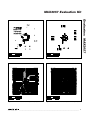
Figure 1 shows the schematic for the MAX2057 EV kit.
C1, C3, C5, and C7 are DC-blocking capacitors for the
IN_A, IN, AMP_IN, and OUT pins. To reduce the possibility of noise pickup from the power supply, capacitors
C2, C4, C6, C8, C9, C10, C13, C14, and C15 are used
to decouple VCC. Resistors R1 and R2 are used to bias
the amplifier’s first and second stages, respectively.
Current-Setting Resistors
The MAX2057 amplifier section is a two-stage design
whose input stage current is set by the external resistor
R1, while the output stage current is set by resistor R2.
These resistors were optimized at the factory to produce the highest OIP3 for a given current. The current
of the device can be reduced by increasing these
resistor values (see the Modifying the EV Kit section),
but linearity performance degrades.
_______________________________________________________________________________________