1
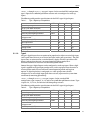
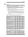
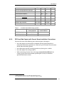
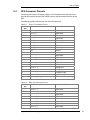
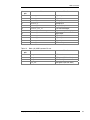
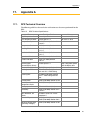
DPS Outputs
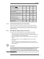
Item
Min
2
6.1.1.1.
Nom
Max
Unit
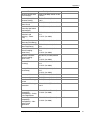
Flyback diode current
-
-
1
A
Short-circuit current limit
(Tjunc = -40ºC to +150ºC)
9
15
23
A
Short-circuit trip time
-
2
-
ms
Thermal protection
-
150
-
ºC
Digital feedback negative threshold
1.5
-
-
V
Digital feedback positive threshold
-
-
3.58
V
Digital feedback cutoff frequency
-
322
-
Hz
Open-load detection – max
detectable load @ 12 V
-
-
1.4
kΩ
Open-load detection pull-up
9.8 k
-
10.2
kΩ
Current sensing
-
No
-
-
Analog feedback
-
No
-
-
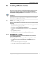
High-Side Output Diagnostics and Fault Protection
Each high-side output has the ability to report many different fault conditions.
The types of faults that are reported are determined by the configuration of your
high-side outputs, and this configuration must be considered when writing the
application software.
6.1.2.
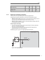
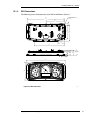
DPS High-Side Output Installation Connections
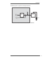
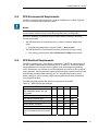
You must be aware of the following when connecting the high-side output:
i
•
The high-side output is connected to an internal bus bar, which can be
connected to a +12 V or +24 V battery. The bus bar is connected to logic power
(VBATT), and both share the same connector pins.
•
The high-side output can provide switched battery power to any load type in a
vehicle.
•
The high-side output can source up to 80mA in the alternator excitation
configuration.
•
The high-side output has an internal flyback diode, which is needed when
driving an inductive load (the flyback diode absorbs electrical energy when the
load is turned off).
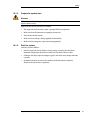
INFORMATION
Inductive loads will create an average current flow that moves out of the high-side
output. When the output is on, the current flows through the output driver, and
when the output is off, the current flows through the flyback diode. A duty cycle of
50% will produce the worst case average current flow through these two devices.
2
This is an average current value, meaning a worst case PWM current of 2 A at 50% duty cycle is possible with
inductive loads.
Display Panel Standard (DPS)
21