1
Coreco Imaging • 6969 Trans-Canada Hwy., Suite 142 • St-Laurent, Quebec, H4T 1V8 • Canada
http://www.imaging.com
Sapera
User’s Manual
Edition 4.20
part number OC-SAPM-USER0
*OC-SAPM-USER0*
NOTICE
© 1998-2002 Coreco Inc. All rights reserved.
This document may not be reproduced nor transmitted in any form or by any means, either electronic or
mechanical, without the express written permission of Coreco Inc. Every effort is made to ensure the
information in this manual is accurate and reliable. Use of the products described herein is understood
to be at the user's risk. Coreco Inc. assumes no liability whatsoever for the use of the products detailed
in this document and reserves the right to make changes in specifications at any time and without
notice.
Microsoft and MS-DOS are registered trademarks; Windows, Windows 95, and Windows NT are
trademarks of Microsoft Corporation.
All other trademarks or intellectual property mentioned herein belong to their respective owners.
Printed on November 15, 2002
Document Number: OC-SAPM-USER0
Printed in Canada
Contents
INTRODUCTION ________________________________________________________________ 1
OVERVIEW OF SAPERA MANUALS............................................................................................................. 1
ABOUT THE MANUAL ............................................................................................................................... 2
USING THE MANUAL ................................................................................................................................. 2
GETTING STARTED _____________________________________________________________ 3
ABOUT SAPERA ........................................................................................................................................ 3
SAPERA PRODUCTS ................................................................................................................................... 4
TWAIN SUPPORT..................................................................................................................................... 4
MICROSOFT® DIRECTSHOW® SUPPORT .................................................................................................. 4
REQUIREMENTS ........................................................................................................................................ 5
Minimum System Requirements ........................................................................................................ 5
Board Requirements (optional) ........................................................................................................ 5
INSTALLATION PROCEDURE ...................................................................................................................... 6
FILE LOCATIONS ....................................................................................................................................... 7
USING SAPERA _________________________________________________________________ 9
CONFIGURING SAPERA .............................................................................................................................. 9
Configuring Contiguous Memory ................................................................................................... 10
Configuring Board’s Serial Ports................................................................................................... 10
DEMOS AND EXAMPLES .......................................................................................................................... 11
Acquiring with GrabDemo ............................................................................................................. 11
Description of Examples................................................................................................................. 13
Description of Demos ..................................................................................................................... 14
USING THE CAMEXPERT TOOL ............................................................................................................... 15
Overview......................................................................................................................................... 15
Features.......................................................................................................................................... 15
Additional Information ................................................................................................................... 17
USING THE APPLICATION WIZARD .......................................................................................................... 17
Step 1 - Overview............................................................................................................................ 17
Step 2 - Define Source of Input Image............................................................................................ 19
Step 3 - Fine Tuning the User Interface ......................................................................................... 20
Step 4 - Processing Images............................................................................................................. 22
Step 5 - Displaying Images............................................................................................................. 23
Sapera User's Manual
Contents • i
SAPERA ARCHITECTURE _______________________________________________________ 25
APPLICATION ARCHITECTURE ................................................................................................................. 25
DEFINITION OF TERMS ............................................................................................................................ 27
LIBRARY ARCHITECTURE........................................................................................................................ 28
DESCRIPTION OF SAPERA MODULES ....................................................................................................... 29
INTRODUCING THE SAPERA API ________________________________________________ 31
THE THREE SAPERA APIS....................................................................................................................... 31
CREATING A C APPLICATION .................................................................................................................. 32
API NAMING CONVENTIONS ................................................................................................................... 33
Functions ........................................................................................................................................ 33
WORKING WITH HANDLES ...................................................................................................................... 35
Getting a Server Handle ................................................................................................................. 35
Getting the resource handle............................................................................................................ 36
ERROR MANAGEMENT ............................................................................................................................ 38
CAPABILITIES AND PARAMETERS ............................................................................................................ 40
ACQUIRING IMAGES ___________________________________________________________ 43
REQUIRED MODULES .............................................................................................................................. 43
ACQUISITION EXAMPLE .......................................................................................................................... 43
MODIFYING THE ACQUISITION PARAMETERS .......................................................................................... 46
USING AN INPUT LOOKUP TABLE ............................................................................................................ 47
DISPLAYING IMAGES __________________________________________________________ 49
REQUIRED MODULES .............................................................................................................................. 49
DISPLAY EXAMPLE ................................................................................................................................. 50
MODIFYING THE VIEW PARAMETERS ...................................................................................................... 51
DISPLAYING IN A WINDOWS APPLICATION .............................................................................................. 53
WORKING WITH BUFFERS______________________________________________________ 55
ROOT AND CHILD BUFFERS ..................................................................................................................... 55
BUFFER TYPES ........................................................................................................................................ 57
READING AND WRITING A BUFFER .......................................................................................................... 59
DRAWING WITHIN IMAGES_____________________________________________________ 63
OVERVIEW .............................................................................................................................................. 63
INITIALIZING THE GRAPHIC ..................................................................................................................... 64
DEFINING GRAPHIC ATTRIBUTES ............................................................................................................ 65
DRAWING SHAPES................................................................................................................................... 66
DRAWING VECTORS ................................................................................................................................ 67
DRAWING TEXT ...................................................................................................................................... 68
APPENDIX A: SUPPORT _________________________________________________________ 69
SUPPORTED OPERATING SYSTEMS .......................................................................................................... 69
SUPPORTED CORECO IMAGING BOARDS ................................................................................................. 69
ii • Contents
Sapera User's Manual
SYSTEM SUPPORT ................................................................................................................................... 70
COBRA/C6 SPECIFIC SUPPORT ................................................................................................................ 71
PYTHON/C6 SPECIFIC SUPPORT .............................................................................................................. 72
APPENDIX B: SERVER MANAGEMENT __________________________________________ 73
THE SERVER DATABASE ......................................................................................................................... 73
THE SAPERA SERVER SERVICE ............................................................................................................... 73
ADDITIONAL SERVERS ............................................................................................................................ 74
SERVER MANAGEMENT DIAGRAM .......................................................................................................... 75
GETTING A SERVER HANDLE (REVISITED)............................................................................................... 76
COMMUNICATING BETWEEN PROCESSES ................................................................................................ 77
APPENDIX C: OTHER TOOLS ___________________________________________________ 79
DIRECTDRAW CAPABILITIES DETECTION TOOL ...................................................................................... 79
FONT GENERATOR TOOL ........................................................................................................................ 80
APPENDIX D: SAPERA RUNTIMES ______________________________________________ 81
INTRODUCTION ....................................................................................................................................... 81
INSTALLING SAPERA RUNTIMES AND SAPERA COMPATIBLE DRIVERS .................................................... 81
Coreco Imaging Installers .............................................................................................................. 82
Silent Mode Installation.................................................................................................................. 82
CORECO IMAGING CONTACT INFORMATION___________________________________ 85
SALES INFORMATION .............................................................................................................................. 85
Corporate Headquarters ................................................................................................................ 85
US Sales Office ............................................................................................................................... 85
TECHNICAL SUPPORT.............................................................................................................................. 86
GLOSSARY OF TERMS _________________________________________________________ 87
INDEX ________________________________________________________________________ 91
Sapera User's Manual
Contents • iii
iv • Contents
Sapera User's Manual
Introduction
Overview of Sapera Manuals
Sapera is supported by five manuals in printed, PDF, and compiled HTML help formats. The following
lists these manuals with a brief description of each.
•
Sapera User’s Manual
This manual introduces Sapera and gives a general overview of its usage as well as installation
procedures.
•
Sapera ActiveX Controls Programmer’s Manual
This manual explains how to program Sapera ActiveX controls.
•
Sapera Sapera++ Programmer’s Manual
This manual describes in detail all the Sapera basic and GUI ‘C++’ classes.
•
Sapera Basic Modules Reference Manual
This manual lists in detail the core Sapera module functions as well as data definitions, file
formats, and macros.
•
Sapera Smart Series and Processing Modules Programmer’s Manual
This manual is a general overview and reference of the image processing and analysis
functions available in Sapera. It also covers installation procedures and processing examples.
Sapera supports some hardware specific extensions (also referred to as board specific modules). The
following manuals, which are provided with the corresponding hardware, describe the hardware
functionality and the supporting API.
•
Sapera CAB Programmer's Manual
This manual introduces CAB (Coreco Auxiliary Bus) and explains how to implement it into a
functional system. It also describes the programming API.
•
Sapera Pixel Processor Modules Programmer's Manual
This manual describes the Pixel Processor and its modules.
Sapera User's Manual
Introduction • 1
About the Manual
This manual exists in printed, Windows Help, and Adobe Acrobat (PDF) formats. The Help and PDF
formats make full use of hypertext cross-references. The PDF format offers links to Coreco Imaging’s
home page on the Internet, located at http://www.imaging.com. Coreco Imaging’s Web site contains
documents, software updates, demos, errata, utilities, and more.
Using the Manual
File names, directories, and Internet sites will be in bold text (e.g., setup.exe, c:\windows,
http://www.imaging.com).
Source code, code examples, and text that must be entered using the keyboard will be in typewriterstyle text (e.g., [PixelClock]).
Menu and dialog actions will be indicated in bold text in the order of the instructions to be executed,
with each instruction separated by bullets. For example, going to the File menu and choosing Save
would be written as File•Save.
2 • Introduction
Sapera User's Manual
Getting Started
About Sapera
Sapera is a high-level library of functions dedicated to image processing and machine vision. The
library API (Application Programming Interface) is composed of a set of C-callable functions classified
into different modules that belong to one of three categories:
• Basic Modules
• Board Specific Modules
• Processing Modules
Basic Modules as well as Processing Modules are device independent. Board Specific Modules are
device dependent.
The Basic Modules constitute the core of the Sapera API. It provides everything you need to acquire,
display, and access images.
The Board Specific Modules provide the hardware specific support functions. The Pixel Processor
and the Coreco Auxiliary Bus (CAB) modules are examples of Sapera hardware specific extensions.
Documentation for the Sapera modules is provided with the related hardware products.
The Processing Modules, as the name implies, provide the image processing functionality of Sapera.
Included are low and high-level optimized image processing functions divided into several groups such
as morphology, point to point operations, etc.
Sapera Smart Series is an extension to the Sapera Processing Modules. This series of modules
includes Smart-Search, a module for pattern locating and alignment; Smart-Matrix, a module for 1D
and 2D barcode recognition; and the Smart-OCR module for optical character and string recognition.
Sapera hardware independent modules allow for one application to control different Coreco Imaging
boards through the same API. It also guarantees seamless migration to any future Coreco Imaging
hardware product supported by Sapera. The modular architecture provides the user with high
programming flexibility and readability.
Sapera User's Manual
Getting Started • 3
Sapera Products
Two different Sapera packages are available:
• Sapera
• Sapera LT
Sapera is Coreco Imaging’s most comprehensive development environment for high performance
image acquisition, processing, and analysis. The Sapera package includes Smart Series.
Sapera LT, a subset of Sapera, contains the Basic and the Board-specific modules only; no image
processing capabilities are provided. Sapera LT is targeted at developers that have their own image
processing libraries and want to interface those libraries to a Sapera compatible frame grabber board.
Sapera LT does include tools such as CamExpert and the Sapera Application Wizard to speed up
application development.
Note: Refer to the Sapera Processing and Smart Series Programmer’s Manual for a detailed
description of these modules.
TWAIN Support
Initially developed to provide a standard software interface to image scanners, the TWAIN standard
has evolved into the imaging industry.
The TWAIN standard is a generic software interface between an application and an imaging device.
Sapera LT runtimes provide TWAIN support that allows a user to control Coreco Imaging boards
through the TWAIN interface without having to directly program any Sapera API.
Microsoft® DirectShow® Support
Sapera runtimes include a Microsoft® DirectShow® compatible driver that allows any Sapera
supported frame grabbers to act as a DirectShow® video source.
4 • Getting Started
Sapera User's Manual
Requirements
Sapera can operate on systems with or without Coreco Imaging boards installed. Operating Sapera on
the system processor without a Coreco Imaging board installed provides only minimal functionality and
performance. Below is a list of the required components for these two operation modes.
Minimum System Requirements
•
•
•
•
PCI-bus IBM PC or compatible with Pentium class or later processor
Microsoft Windows NT 4.0 Service Pack 6, Microsoft Windows 2000, Microsoft
Windows XP, or Microsoft Windows NT Embedded
One of the following C-language compilers:
- Visual C++, version 6.00 or later.
- Borland C++ Builder, version 4.00 or later.
OR
One of the following compilers that support Active X technology:
- Visual C++, version 6.00 or later.
- Visual Basic 4.00 or later.
- Borland C++ Builder, version 4.00 or later.
- Borland Delphi, version 5.00 or later.
Board Requirements (optional)
•
•
One of several Sapera compatible boards (see "Supported Coreco Imaging Boards" on
page 69).
Corresponding Sapera-compatible board drivers
Sapera User's Manual
Getting Started • 5
Installation Procedure
Note: Before installing Sapera, make certain that your current VGA display mode is set to display at
least 256 colors Some Sapera features require DirectDrawTM, which will not work with a smaller
number of display colors.
The following steps describe how to install Sapera on your hard drive:
1. Insert the Sapera installation CD-ROM in a CD-ROM drive.
2. A CD Browser screen will appear automatically. If not, from Windows Explorer, run the
launch.exe application located in the root directory of the Sapera CD.
3. Go to the Sapera Installation menu to begin Sapera installation.
4. Launch Sapera LT installation and follow the on-screen instructions.
5. Install Sapera Processing and Smart Series if the full Sapera package was purchased.
Refer to the Sapera Processing and Smart Series Programmer’s Manual to finalize the
configuration of the library.
6. You may install the required board level drivers without rebooting the computer at this
time; however, note that you must reboot the computer to finish the installation of Sapera.
7. Reinsert the Sapera CD or run the launch.exe application again.
8. Go to the Hardware Device Drivers menu to install the required board level drivers for
your installed Sapera supported hardware.
9. Reboot the computer when prompted to complete the software installation.
6 • Getting Started
Sapera User's Manual
File Locations
The table below lists the different file groups and locations:
Description
Location
Utility programs
\sapera\bin
Camera files
\sapera\camFiles
Class files (Sapera++)
\sapera\classes
Demonstration programs
\sapera\demos
Example programs
\sapera\examples
Font files
\sapera\fonts
Help files
\sapera\help
Image files
\sapera\images
Header files
\sapera\include
Import libraries
\sapera\lib
Pixel Processor High Level
Library source code
\sapera\pixpro
Dynamic-link libraries (DLLs)
and ActiveX controls (OCXs)
Windows system directory (winnt\system32)
Device driver files
Windows driver directory (winnt\system32\drivers)
Sapera User's Manual
Getting Started • 7
8 • Getting Started
Sapera User's Manual
Using Sapera
Configuring Sapera
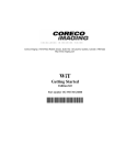
The Sapera Configuration program (SapConf.exe) allows you to see all the Sapera-compatible
boards present within your system. It may also be used to adjust the amount of contiguous memory to
be allocated at boot-time. After activating this program, it displays all the servers related to the installed
boards as shown in the figure below. See "Supported Coreco Imaging Boards" on page 69 for a current
list of Sapera supported boards.
The System entry represents the system server. It corresponds to the host machine (your computer),
and is the only server that should always be present. The other servers correspond to the board’s
presence within the system. To update the server list, use the Refresh button at any time.
Sapera User's Manual
Using Sapera • 9
Configuring Contiguous Memory
The Contiguous Memory section lets you specify the total amount of contiguous memory to be
reserved for allocating buffers and messages.
Note: All Sapera demos and examples don’t use contiguous memory. Therefore, you should not
modify these settings unless your application requires contiguous memory.
The Requested value displays what was requested; the Allocated value displays the amount of
contiguous memory that was allocated successfully. The current value for buffers determines the total
amount of contiguous memory reserved at boot-time for the allocation of dynamic resources (e.g.,
buffers, lookup tables, kernel). Adjust this value according to the need of your application for
contiguous memory. The current value for messages determines the total amount of contiguous
memory reserved at boot-time for the allocation of messages. This memory space is used to store
arguments when a Sapera function is called. Increase this value if you are using functions with large
arguments, such as arrays.
Configuring Board’s Serial Ports
Certain frame grabber boards provide an onboard serial port for direct camera control by the frame
grabber. Refer to the board’s user manual for information on how to configure and use it.
10 • Using Sapera
Sapera User's Manual
Demos and Examples
Sapera comes with several generic demos and examples. In this section, we provide a description of
each of them.
Certain board driver installations provide other demos and examples that demonstrate the specific
usages and capabilities of the board. Refer to a specific board user’s manual for further details.
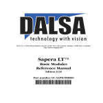
Acquiring with GrabDemo
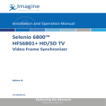
The GrabDemo allows you to grab and display a live image within a host buffer. It can
accommodate any Sapera-compatible board with any camera. This demo is a good starting-point
when verifying that your camera and frame grabber are properly installed.
The following dialog box appears when starting GrabDemo:
You must select the Acquisition Server and the Acquisition Device. The first one corresponds to
the board you want to grab from; the second one represents the acquisition device on this board
(some boards may have more than one).
You must then select a camera file (CAM File) compatible with your camera from the list of
available files. A video-input-conditioning file (VIC File) is also required. This VIC file is specific
to the frame grabber you select. You can use the Generate Default option to create a default VIC
file since they are not provided with Sapera. CamExpert may be used to generate specialized VIC
files (e.g., external trigger, cropping window, etc).
Note: No frame-grabber was found within your system if this dialog box does not appear. In such a
case, verify that the device driver corresponding to your frame-grabber was correctly installed. The
Sapera User's Manual
Using Sapera • 11
Sapera Configuration Program gives you the list of boards present within your system. This demo
can work without a frame-grabber; although, it only allows you to load the file from disk.
Click OK to start the demo.
Using the GrabDemo you can now:
1.
Control the acquisition using the Snap, Grab, Freeze, and Abort buttons.
2.
Load/save image(s) from/to disk using the Load and Save buttons.
3.
Dynamically adjust the acquisition parameters through the General, Area scan, Linescan,
and Composite buttons.
4.
Reload the CAM and VIC files using the Load CAM/VIC button (this overwrites all the
parameters modified in step 3).
5.
The Buffer button allows you to change the number of buffers used for the internal cycling
and the type of buffer (contiguous, scatter-gather, off-screen, or overlay).
12 • Using Sapera
Sapera User's Manual
Description of Examples
Several example programs are available within Sapera. These examples are essentially basic
applications demonstrating simple tasks like grabbing an image and loading an image file from disk.
The main purpose of the examples is to provide the user with code samples that can be easily extracted
and integrated into an application.
There is a common Visual C++ workspace (\Sapera\Examples\SapExamples.dsw) that includes all
example projects. This workspace allows you to recompile all the examples in a batch.
The table below describes the different example programs:
FileLoadC Example
\Sapera\Examples\Standard\Vc\FileLoadConsole\Release\FileLoadC.exe
This example shows how to load an image file from the disk into a Sapera buffer and then display it. The
buffer is created according to the image file properties. One of several images (monochrome, RGB, or YUV)
can be selected for loading. This example uses the Sapera Standard C API.
FileLoadCPP Example
\Sapera\Examples\Classes\Vc\FileLoadConsole\Release\FileLoadCPP.exe
Same as FileLoadC Example, but uses the Sapera++ API.
FileLoadMFC Example
\Sapera\Examples\Classes\Vc\FileLoadMFC\Release\FileLoadMFC.exe
Same as FileLoadCPP Example, but additionally uses the GUI Sapera++ classes to allow for the use of a file
browser.
GrabC Example
\Sapera\Examples\Standard\Vc\GrabConsole\Release\GrabC.exe
This example shows how to grab an image from an RS-170 or PAL camera into a Sapera buffer and then
display it. The buffer is created according to the camera settings. Any Sapera compatible board supporting an
analog input can be used. This example uses the Sapera Standard C API.
GrabCPP Example
\Sapera\Examples\Classes\Vc\GrabConsole\Release\GrabCPP.exe
Same as GrabC Example, but uses the Sapera++ API.
GrabMFC Example
\Sapera\Examples\Classes\Vc\GrabMFC\Release\GrabMFC.exe
Same as GrabCPP, but additionally uses the GUI Sapera++ classes to allow for selecting the board and
camera using dialog boxes.
Sapera User's Manual
Using Sapera • 13
Description of Demos
Several demo programs are available within Sapera. These demos are more complete applications than
the supplied examples.
The main purpose of the demos is to provide the user with a starting application that can be modified in
order to become the user’s end application.
There is a common Visual C++ workspace (\Sapera\Demos\Classes\Vc\SapDemos.dsw) that includes
all the demo projects (except ActiveX demos). This workspace allows you to recompile all the demos
in a batch.
The table below describes the different demo programs:
Grab Demo
\Sapera\Demos\Classes\Vc\GrabDemo\Release\GrabDemo.exe
This program demonstrates the basic acquisition functions included in the Sapera library. It allows you to
acquire images, either in continuous or in one-shot mode, while adjusting the acquisition parameters.
The minimum requirements to run this demo are a Sapera-compatible frame-grabber and an analog or digital
camera.
This demo is built using Visual C++ 6.0 and the MFC library It is based on the Sapera++ API. See the
Sapera++ Programmer’s Manual for more information.
Advanced Grab Demo
\Sapera\Demos\Classes\Vc\AdvGrabDemo\Release\AdvGrabDemo.exe
This program has the same functionality as GrabDemo, but additionally includes support for the CAB, Pixel
Processor, and DSP.
The minimum requirements to run this demo are a Sapera-compatible frame-grabber and an analog or digital
camera. The other devices (CAB, Pixel Processor, and DSP) are optional.
This demo is built using Visual C++ 6.0 and the MFC library. It is based on the Sapera++ API. See the
Sapera++ Programmer’s Manual for more information.
Sequential Grab Demo
\Sapera\Demos\Classes\Vc\SeqGrabDemo\Release\SeqGrabDemo.exe
This program demonstrates how to grab a sequence of images into memory and then display it. The program
allows you to record several images and then load and save AVI files. Each image is stored in its own buffer
and can be reviewed. A small number of images are allocated by default, but it can be increased using the
buffer options inside the demo.
To run this demo, the minimum requirements are a Sapera-compatible frame-grabber and an analog or digital
camera.
This demo is built using Visual C++ 6.0 and the MFC library. It is based on the Sapera++ API. See the
Sapera++ Programmer’s Manual for more information.
14 • Using Sapera
Sapera User's Manual
ActiveX Acquisition Demo (Visual Basic Version)
\Sapera\Demos\ActiveX\Vb\AcqDemo\VbAcqDemo.exe
\Sapera\Demos\ActiveX\Vb\AcqDemo\VbAcqDemo.vbp
This demo allows the user to grab an image from a specified acquisition device to a host buffer. This demo is
built using Visual Basic 6.0 and is based on the Sapera ActiveX controls. See the Sapera ActiveX Controls
Manual for more information.
ActiveX Acquisition Demo (Visual C++ Version)
\Sapera\Demos\ActiveX\Vc\AcqDemo\Release\VcAcqDemo.exe
\Sapera\Demos\ActiveX\Vc\AcqDemo\VcAcqDemo.dsp
This demo allows the user to grab an image from a specified acquisition device to a host buffer. This demo is
built using Visual C++ 6.0 and is based on the Sapera ActiveX controls. See the Sapera ActiveX Controls
Manual for more information.
Using the CamExpert Tool
Overview
Sapera applications need to load the appropriate camera file (CAM) and video-input-conditioning file
(VIC) before acquiring images from a camera. The files containing these parameters have the
extensions .cca and .cvi, respectively. The CAM file contains the parameters specific to the camera
whereas the VIC file contains frame-grabber related parameters.
A set of predefined camera files for the most common camera types (including NTSC and PAL) is
provided within Sapera. With the CamExpert tool, if loading one of these CAM files, a set of default
VIC parameters is automatically generated for the currently selected frame-grabber. You can then save
those parameters in a VIC file for later use by your application.
You can also modify the VIC parameters before saving them. This allows you to specialize your VIC
file (e.g., enabling the external trigger, changing the cropping window, etc).
Use CamExpert to generate a CAM file in the special case in which you have a camera for which there
are currently no available CAM files.
Features
•
Uses Sapera ActiveX controls; therefore, it supports any Coreco Imaging hardware currently
supported by Sapera.
•
Creation and modification of camera (CAM) and video-input-conditioning files (VIC).
•
Grouping of acquisition parameters into related categories for easier access to any specific
parameter.
•
Built-in expert system for intelligent management of relationships between the various
parameters.
Sapera User's Manual
Using Sapera • 15
•
Intelligent editing of video timings, through a locking mechanism that allows explicit
modification of some values and automatic recalculation of the remaining ones.
•
Online operation mode that allows live acquisition of images as the parameters are specified
and modified.
•
Offline operation mode that retains all program functionality (except live grab) so that
configuration files may be created or modified even in the absence of acquisition hardware.
•
Online help system
16 • Using Sapera
Sapera User's Manual
Additional Information
Refer to the following for further information:
• For Sapera’s camera, video-input-conditioning, and Acquisition modules, see the Sapera
Basic Modules Reference Manual.
• For Sapera ActiveX controls, see the Sapera ActiveX Controls Programmer’s Manual.
See either the corresponding board User’s manual or search within this manual for limitations
applicable to specific Coreco Imaging hardware.
Using the Application Wizard
Step 1 - Overview
The Sapera Application Wizard allows code generation for simple applications involving a single
acquisition device (e.g., Bandit-II) in a host computer. Other features (CAB transfers, processing on the
Pixel Processor, distributed applications on multiple vision processors, etc.) will be introduced in future
wizards.
The Sapera Application Wizard generates dialog-based MFC applications that use the Sapera++ classes
introduced with Sapera 4.0.
The Sapera++ Basic Classes encapsulate all the Sapera API calls. They address the basic imaging
concepts, i.e., acquisition, display, processing, and buffers.
The Sapera++ GUI Classes provide the user with MFC-based dialog boxes commonly used in most
imaging applications.
Refer to Sapera++ Programmer’s Manual for information on the classes.
Below is a screen shot of the first step within the Sapera Application Wizard that essentially describes
what the Sapera Application Wizard can do.
Sapera User's Manual
Using Sapera • 17
Note: There exists a stand-alone version of the Sapera Application Wizard (distributed separately
from the Sapera library). This version allows application code generation. This code, however, cannot
be compiled.
18 • Using Sapera
Sapera User's Manual
Below is a typical user application interface obtained by using the Sapera Application Wizard.
Step 2 - Define Source of Input Image
Location
If the option “Select an acquisition device installed in host computer...” is chosen (not available in the
stand-alone version) a dialog box is displayed for the user to chose the acquisition server and device
immediately. The acquisition server refers to the frame-grabber (e.g., Viper_Quad_1) while the
acquisition device is the name of the input device (e.g., Single Channel 1).
Sapera User's Manual
Using Sapera • 19
Acquisition Configuration (CAM and VIC files)
Two files are needed to configure image acquisition:
•
A camera configuration file (or CAM file, with a .CCA file extension) and...
•
A video-input-conditioning file (or VIC file, with a .CVI file extension).
A large database of CAM files are distributed with Sapera that cover a wide range of camera
manufacturers and models. Select the one that is compatible with your camera.
A default VIC file can be automatically generated using the Generate Default button. Use the
CamExpert tool to create a specialized VIC file.
Step 3 - Fine Tuning the User Interface
It is sometimes more convenient to set some acquisition parameters individually and directly from
within the application rather than using CamExpert to generate VIC files for all possible combinations.
The Sapera Classes define a few standard GUI dialog boxes that allow the user to change a selection of
frequently used parameters. The screen shot below shows the category list of parameters you can
enable.
20 • Using Sapera
Sapera User's Manual
Below is a brief description of the parameters that you can access via the different categories:
Video-input-conditioning
• Brightness and contrast options
• Hue and saturation options
Miscellaneous controls
• Camera selector
• Digital input connect bit ordering
• External trigger options
Area-scan camera control
• Trigger/reset/integrate options
• Master mode (camera slave) options
Linescan camera control
• Line triggering options
• Frame triggering options
• Shaft encoder options
• Linescan direction options
Sapera User's Manual
Using Sapera • 21
Step 4 - Processing Images
If you do not intend to process the images, it is preferable to select “Application involves image display
only”. The application created by this wizard will attempt to transfer the images directly from
acquisition device to video adapter in order to minimize CPU load.
If you choose to add support for image processing, this wizard will add controls to the application for
the user to enable/disable image processing. If the processing is enabled, the processed images will be
displayed; otherwise, the unprocessed images will be displayed.
If you select the “Add GUI controls to let user set ROI” option, user controls will be added within the
application along with the code needed to display the location of the ROI on the image.
22 • Using Sapera
Sapera User's Manual
Step 5 - Displaying Images
If you select the “Enable graphics overlay” option, the wizard will write code that will attempt to use
the display adapter’s overlay hardware acceleration. If it is not available, then the overlay will be drawn
by software for each displayed frame.
Event Notification
For synchronization purposes, you may register your functions called by Sapera at specific events, like
the end of a frame’s acquisition. In this step, you can select which events will trigger a Sapera
Application Wizard written function to get called. Note that some events may have been automatically
selected depending on your answers in the previous steps of the wizard.
Sapera User's Manual
Using Sapera • 23
24 • Using Sapera
Sapera User's Manual
Sapera Architecture
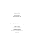
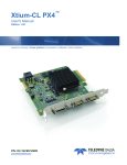
Application Architecture
Whichever API is used (C, C++, or ActiveX), the Sapera modular architecture allows applications to be
distributed on different Sapera servers. Each server can run either on the host computer or on a Coreco
Imaging board. Sapera calls are routed to different servers via the Sapera messaging layer in a fashion
completely independent of the underlying hardware.
Sapera User's Manual
Sapera Architecture • 25
User Application
Sapera++ (C++)
ActiveX Controls
Standard API (C)
Host Server
Messaging Layer
Basic
Modules
Processing
Modules
Board 1 Server
Board 2 Server
Board N Server
Basic
Modules
Basic
Modules
Basic
Modules
Processing
Modules
Processing
Modules
26 • Sapera Architecture
...
Processing
Modules
Sapera User's Manual
Definition of Terms
What is a server?
A Sapera server is an abstract representation of a physical device like a frame-grabber, a processing
board, or a desktop PC. In general, a Coreco Imaging board is a server. Some processing boards,
however, may contain several servers; this is true when using multi-processor boards.
A server allows Sapera applications to interact with the server’s resources.
What is a static resource?
Resources attached to a physical device are called static resources. For example, a frame grabber can
have an acquisition resource, display resource, and a processor resource. These resources can be
manipulated to control a physical device through a Sapera server.
What is a dynamic resource?
A dynamic resource is an abstract representation of data storage (such as a buffer, lookup table, object,
etc.) or links that connect the data storage to static resources. Unlike static resources, dynamic
resources are not dependent on physical devices; therefore, users on a specified server can freely create
dynamic resources.
What is a module?
A module is a set of functions used to access and/or control a static or a dynamic resource. The
complete Sapera API is composed of a series of modules organized in a particular architecture. These
modules are described in the "Description of Sapera Modules" on page 29 section.
Sapera User's Manual
Sapera Architecture • 27
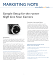
Library Architecture
The block diagram below illustrates the Sapera Library architecture illustrating all the module
interconnections. In this diagram, standard rectangles (above the dashed line) represent dynamic
resource modules while rounded rectangles (below the dashed line) represent static resource modules.
Basic & Board-specific Modules
Cam
Vic
File
Buffer
Lut
Dynamic
Resource
Modules
Xfer
Acq
Cab
28 • Sapera Architecture
PixPro
View
Display
Graphic
Static
Resource
Modules
Sapera User's Manual
Description of Sapera Modules
Below is a brief description of the modules (blocks) and their connections to other modules.
Camera Module (Cam)
The Camera module refers to a dynamic resource. It is used for grouping and storing acquisition
parameters related to the camera. Parameter examples include video format, the number of input bits,
and the pixel clock. This module is used by the Acquisition module to transfer parameters to/from the
acquisition device.
Video-Input-Conditioning Module (VIC)
The Video Input Conditioning module refers to a dynamic resource. It is used for grouping and storing
acquisition parameters related to the digitization device. Parameter examples include brightness,
contrast, and saturation. This module is used by the Acquisition module to transfer parameters to/from
the acquisition device.
Buffer Module (Buffer)
The Buffer module refers to a dynamic resource. The module includes the functionality to manipulate a
generic buffer that can be either one-dimensional (a vector) or two-dimensional (an image). Buffers are
the base data storage resources of Sapera. The Buffer module is used by the Transfer, View, Graphic,
and Processing modules.
LookUp Table Module (Lut)
The LookUp Table module refers to a dynamic resource. The module includes the functionality to
manipulate a generic LookUp table. The LookUp Table may be used as an input (in an acquisition
process), an output (in a display process), or processing LookUp Table. The Lookup Table module is
used by the Acquisition, View, and Processing modules.
Transfer Module (Xfer)
The Transfer module refers to a dynamic resource. It is used to establish a connection and perform a
data transfer between a source and a destination resource. For example, it is used to control an
acquisition process by using the Acquisition resource as the source and a Buffer resource as the
destination. The Transfer module uses the Acquisition, Buffer, Cab, and Pixel Processor modules.
View Module (View)
The View module refers to a dynamic resource. It is used to establish a connection and perform a data
transfer between the Buffer and Display resources. For example, it is used to display a buffer by
transferring its data from system memory to video memory. The View module uses the Buffer and
Display modules.
Sapera User's Manual
Sapera Architecture • 29
File Module (File)
The File module refers to a dynamic resource. It is used to exchange images between buffers and files.
Various file formats are supported (e.g., TIFF, BMP, RAW, JPEG, AVI, and the Coreco Imaging
Custom Format).
Acquisition Module (Acq)
The Acquisition module refers to a static resource. It is used to control an acquisition device that is
present on any Coreco Imaging board that supports an acquisition section (see Appendix A: Support on
page 69). The Acquisition module includes the functionality to read and write the acquisition
parameters individually. Optionally, it can work in conjunction with both the Camera and Video Input
Conditioning modules for grouping and storing parameters. The Transfer module, however, is required
for synchronizing (starting or stopping) the acquisition process. This module is used by the Transfer
module and uses the Camera and Video Input Conditioning modules.
Display Module (Display)
The Display module refers to a static resource. It is used to control a display device that is present on
the system display (your computer video card) or on any Coreco Imaging board supporting a display
section. The Display module includes the functionality to read and write display parameters. In cases
where the buffer is located outside video memory (system memory or off-screen memory), the View
module transfers data to video memory. The Display module is used by the View module.
Graphic Module (Graphic)
The Graphic module refers to a static resource. It is used to control a graphic or processing device that
is present in the system (your system CPU) or on any Coreco Imaging board supporting an onboard
graphic or other processing device. The Graphic module includes the functionality to manipulate
drawing shapes, vectors, and text within a buffer. The Graphic module uses the Buffer module.
Coreco Auxiliary Bus Module (Cab)
The Coreco Auxiliary Bus (CAB) module refers to a static resource. It is used to control the Coreco
Auxiliary Bus device. The CAB is typically used for transferring data between two Coreco Imaging
boards. This module is used by the Transfer module. For more information, consult the Sapera CAB
Programmer’s Manual.
Pixel Processor Module (PixPro)
The Pixel Processor module refers to a static resource. It controls the Pixel Processor daughter card
that plugs into certain Coreco Imaging boards. The Pixel Processor is often used for applying simple
pre-processing to an image. The Pixel Processor module is used by the Transfer module. For more
information, consult the Sapera Pixel Processor Module Programmer’s Manual.
30 • Sapera Architecture
Sapera User's Manual
Introducing the Sapera API
The Three Sapera APIs
Three different APIs are available under Sapera:
1.
Sapera Standard API (based on C language)
2.
Sapera++ Classes (based on C++ language)
3.
Sapera ActiveX Controls (language independent)
The following sections will illustrate the C API. For C++ and ActiveX API information consult the
Sapera++ Programmer’s Manual and the Sapera ActiveX Controls Programmer’s Manual
respectively.
Sapera User's Manual
Introducing the Sapera API • 31
Creating a C Application
The following files are required to compile and link the Sapera program:
File Name
Description
Location
corapi.h
Main header file
\sapera\include
corapi.lib
Import library for corapi.dll
\sapera\lib
Follow the steps below to compile and link:
1. Include corapi.h in the program source code. This header file will include all other
required headers.
2. Add $(saperadir)\include to the compiler's include path.
3. Insert corapi.lib in the project file list.
4. In Project | Settings… | C/C++ | Code Generation | Use run-time library, choose the
option Multithreaded DLL (in release mode) or Debug Multithreaded DLL (in debug
mode).
Note: Step 4 is required because the Sapera library is compiled with the Multithreaded DLL version of
the Microsoft runtime library. If your application contains other DLL components, compile these
DLLs with the same option.
32 • Introducing the Sapera API
Sapera User's Manual
API Naming Conventions
Functions
The API functions follow standard naming conventions. First, all API functions are prefixed with
“Cor”, derived from “Coreco”. This prefix is followed by the module name, as described before in the
architecture, and next by the function name. All functions also return an error code. Below is the syntax
description with some examples.
CORSTATUS Cor<module name><function name>(...)
Examples:
CORSTATUS status;
status = CorBufferClear(...)
status = CorXferStart(...)
status = CorLutNormal(...)
//
//
//
//
Status code
Clear function of Buffer module
Start function of Transfer module
Generate a normal lookUp table
Handles
All API functions refer to a server and/or a module handle (see “Working with Handles” on page 35).
The server handle is always named CORSERVER. The module handles use the following syntax:
COR<module name>
Examples:
CORSERVER hServer;
CORBUFFER hBuffer;
CORACQ hAcq;
CORDISPLAY hDisplay;
Sapera User's Manual
//
//
//
//
Handle
Handle
Handle
Handle
to
to
to
to
a server
a buffer
an acquisition
a display
Introducing the Sapera API • 33
Capabilities and Parameters
Each resource may have a series of capabilities and parameters (see “Capabilities and Parameters” on
page 40) that follow the syntax below:
For a capability number:
COR<module name>_CAP_<capability name>
For a parameter number:
COR<module name>_PRM_<capability name>
And for each of the possible values:
COR<module name>_VAL_<capability name>_<value description>
Examples:
CORACQ_CAP_CHANNEL
CORACQ_PRM_CHANNEL
// Capability Channel of Acquisition module
// Parameter Channel of Acquisition module
CORACQ_VAL_CHANNEL_SINGLE
CORACQ_VAL_CHANNEL_DUAL
// Single channel value for Acquisition module
// Dual channel value for Acquisition module
Enumerated Arguments
A function may have one or more enumerated arguments. The list of possible values for such
arguments are as follows:
COR<module name>_<value description>
Example:
CORBUFFER_FILEFORMAT_BMP
CORBUFFER_FILEFORMAT_TIFF
// Bitmap file format in the buffer module
// TIFF file format in the buffer module
34 • Introducing the Sapera API
Sapera User's Manual
Working with Handles
Accessing resource data in Sapera can only be accomplished by calling an API function. Therefore,
servers and resources are all assigned a handle. A handle is a structure containing the necessary
information to access internal resource data. To get a handle to a resource involves two steps:
1. Getting a server handle.
2. Getting the resource handle.
Getting a Server Handle
There are three ways to get a server handle in Sapera:
1. The default server, on which the current application is running, is obtained by calling the
following function:
CORSERVER hServer;
// Declare a server handle
// Get the default server handle
hServer = CorManGetLocalServer();
2. You may also enumerate all of the currently available Sapera servers, using for each an
index that ranges from 0 to nServer-1, where nServer is the number of servers found by the
API.
CORSTATUS status;
UINT32 nCount;
UINT32 nIndex;
char szName[64];
CORSERVER hServer;
//
//
//
//
//
Declare
Declare
Declare
Declare
Declare
status code
a server count
a server index
a character string for returned name
a server handle
// Get the server count
status = CorManGetServerCount(&nCount);
// Get the server handle from an index
status = CorManGetServerByIndex(nIndex, szName, &hServer);
3. You may also specify the exact server name (see Appendix A: Support on page 69 for a
list of supported Coreco Imaging boards and the default names of their servers).
CORSTATUS status;
CORSERVER hServer;
// Declare status code
// Declare a server handle
// Get the server handle by specifying a name
status = CorManGetServerByName("Bandit_II_1", &hServer);
Sapera User's Manual
Introducing the Sapera API • 35
Use the following function to release the server handle when you have finished using it:
CORSTATUS status;
CORSERVER hServer;
// Declare status code
// Declare a server handle
// Release the specified server handle
status = CorManReleaseServer(hServer);
A more comprehensive discussion on this topic is found in the section “Appendix B: Server
Management” on page 73.
Getting the resource handle
Getting a Handle to a Static Resource
As noted in the Architecture Section, static resources are related to devices on a server. Therefore, their
number depends on the specific server where they are located. Each static resource module includes a
function to access the resource count, as in the following example:
CORSTATUS status;
CORSERVER hServer;
UINT32 nAcqCount;
UINT32 nDisplayCount;
//
//
//
//
Declare
Declare
Declare
Declare
status code
a server handle
a acquisition count
a display count
// Get server handle
...
status = CorAcqGetCount(hServer, &nAcqCount);
status = CorDisplayGetCount(hServer, &nDisplayCount);
// Get acquisition count
// Get display count
You then obtain the resource handle by specifying an index ranging from 0 to nxxxCount-1. When the
handle is no longer used, it must be released.
CORSTATUS status;
CORSERVER hServer;
CORACQ hAcq;
CORDISPLAY hDisplay;
//
//
//
//
Declare
Declare
Declare
Declare
status code
a server handle
an acquisition handle
an display handle
// Get server handle
...
// Get resource handles
status = CorAcqGetHandle(hServer, 0, &hAcq);
status = CorDisplayGetHandle(hServer, 0, &hDisplay);
// Use them
...
// Release handles when finished
status = CorAcqRelease(hAcq);
status = CorDisplayRelease(hDisplay);
36 • Introducing the Sapera API
Sapera User's Manual
Creating a Handle for a Dynamic Resource
Because dynamic resources are not device-based their potential number is unlimited. Each dynamic
resource has its own creation arguments. Below is an example showing the creation of a buffer and a
lookup table.
CORSTATUS status;
CORSERVER hServer;
CORBUFFER hBuffer;
CORLUT hLut;
//
//
//
//
Declare
Declare
Declare
Decalre
status code
a server handle
a buffer handle
a LUT handle
// Get server handle
...
// Create resource handles
status = CorBufferNew(hServer, 640, 480, CORBUFFER_VAL_FORMAT_UINT8, 0, &hBuffer);
status = CorLutNew(hServer, 256, CORLUT_VAL_FORMAT_UINT8, &hLut);
// Use them
...
// Free handles when finished
status = CorBufferFree(hBuffer);
status = CorLutFree(hLut);
Sapera User's Manual
Introducing the Sapera API • 37
Error Management
Interpreting Status Codes
All Sapera functions return a status code. If an error is detected, this code describes the nature and the
level of the error within the called function. Some status codes also contain additional information
related to the specific error. Furthermore, all status codes include a module identifier that indicates
which module the function belongs to. The example below demonstrates how to get the different fields
of the status code.
CORSTATUS status;
UINT32 errorId;
UINT32 errorInfo;
UINT32 errorLevel;
UINT32 module;
//
//
//
//
//
Status code
Error identifier
Additional specific information
Error level
Module of the function called
// Call an API function
status = CorXXX(...);
//
//
//
//
Extract the status code's ID
If the function succeeds will return CORSTATUS_OK,
otherwise will return CORSTATUS_xxx.
See Reference Manual for the complete list of error ID's
errorId = CORSTATUS_ID(status);
//
//
//
//
Extract the status code's additional information
This information is specific to the status code's ID
Some status code don't support this field
See Reference Manual for a detailed description of the values.
errorInfo = CORSTATUS_INFO(status);
//
//
//
//
//
//
Extract the status code's level
Will return one of the following values:
CORSTATUS_LEVEL_FAT
Fatal error
CORSTATUS_LEVEL_ERR
General error
CORSTATUS_LEVEL_WRN
Warning
CORSTATUS_LEVEL_INF
Information
errorLevel = CORSTATUS_LEVEL(status);
//
//
//
//
//
//
Extract the module
Will return one of the module identifier:
CORSTATUS_MODULE_ACQ
CORSTATUS_MODULE_BUFFER
...
See Reference Manual for the complete list of modules
module = CORSTATUS_MODULE(status);
38 • Introducing the Sapera API
Sapera User's Manual
You can obtain an associated description string by calling the function CorManGetStatusText, which
returns a string including a description of the status code.
CORSTATUS status;
char szText[256];
// Status code
// Status text
// Call an API function
status = CorXXX(...);
// Get the associated text string
CorManGetStatusText(status, szText, sizeof(szText), NULL, 0);
You can also obtain more detailed information by calling the function CorManGetStatusTextEx,
which returns a string for each field of the status code.
CORSTATUS status;
char id[128], info[128], level[64], module[64];
// Call an API function
status = CorXXX(...);
// Get the associated text strings
CorManGetStatusTextEx(status, id, sizeof(id), info, sizeof(info), level,
sizeof(level), module, sizeof(module));
Monitoring Sapera Errors
The logview.exe utility program included with Sapera provides an easy way to view status code
returned by API functions. logview.exe is a simple Windows program that includes a list box that
stores the status code description strings as soon as they are logged in the API. Options allow you to
modify the different fields for display.
It is recommended to start LogView before starting your application and then let it run so it can be
referred to any time a detailed error description is required. However, errors are also stored by a lowlevel service (running in the background), even if LogView is not running. Therefore, it is possible to
run it only when a problem occurs while running your application.
Sapera User's Manual
Introducing the Sapera API • 39
Capabilities and Parameters
Resources can be characterized by a set of capabilities and parameters. Together they define a
resource's ability and current state.
What is a Capability?
A capability, as its name implies, is a value or set of values that describe what a resource can do.
Capabilities are used to determine the possible valid values that can be applied to a resource's
parameters. They are read-only.
Accessing a Capability
A capability can be obtained from a resource by using the Cor<module name>GetCap function. It has
the following prototype:
CorxxxGetCap(CORxxx handle, UINT32 cap, void *value)
• handle: valid handle to a resource
• cap: valid capability of the resource
• value: buffer of proper size to store the capability value(s). The size of a capability can be
obtained by using the macro CORCAP_GETSIZE(cap)
What is a Parameter?
A parameter describes a characteristic of a resource. It can be read/write or read-only.
40 • Introducing the Sapera API
Sapera User's Manual
Accessing a Parameter
A parameter can be read by using the Cor<module name>GetPrm function. It has the following
prototype:
CorxxxGetPrm(CORxxx handle, UINT32 prm, void *value)
• handle: valid handle to a resource
• prm: valid parameter of the resource
• value: buffer of proper size to store the parameter value. The size (in bytes) of a
parameter can be obtained by using the macro CORPRM_GETSIZE(prm)
You can write parameters with the Cor<module name>SetPrm and Cor<module name>SetPrmEx
functions. They have the following prototypes:
CorxxxSetPrm(CORxxx handle, UINT32 prm, UINT32 value)
CorxxxSetPrmEx(CORxxx handle, UINT32 prm, const void *value)
• handle: valid handle to a resource
• prm: valid parameter of the resource
• value: buffer of proper size to store the parameter value. The size in bytes of a parameter
can be obtained by using the macro CORPRM_GETSIZE(prm)
The "Ex" function is used to write to a parameter whose value is greater than four bytes.
Sapera User's Manual
Introducing the Sapera API • 41
42 • Introducing the Sapera API
Sapera User's Manual
Acquiring Images
Required Modules
You need the three following Sapera modules to initiate the acquisition process:
• Acquisition: Static resource based on an onboard acquisition section.
• Buffer: Dynamic resource used to store the acquired data. The buffer must be allocated
using the CORBUFFER_VAL_TYPE_CONTIGUOUS or
CORBUFFER_VAL_TYPE_SCATTER_GATHER buffer type to enable the transfer (see
"Working with Buffers" section on page 55 for more information about contiguous
memory and scatter-gather).
• Transfer: Dynamic resource used to link the acquisition to the buffer and to synchronize
the acquisition operations.
Acquisition Example
The example below demonstrates how to grab a live image into a buffer allocated in system memory,
using the Bandit-II board as an acquisition resource. See Appendix A: Support on page 69 for a list of
Coreco Imaging boards equipped with an acquisition section.
As shown in the example, acquiring an image requires two files to configure the acquisition hardware: a
CAM file and a VIC file. The former defines the characteristics of the camera whereas the latter defines
how the camera and the acquisition hardware will be used. Refer to the section “Using the CamExpert
Tool” on page 15 for a discussion on how to obtain these files. CAM and VIC resource parameters can
also be accessed individually. For more information, refer to section “Modifying the Acquisition
Parameters” (page 46).
Once the acquisition module is initialized using the CAM and VIC files, some parameters are retrieved
from it (acquisition width, height, and format) and are used to create a compatible buffer.
Before starting the transfer, you must create a transfer path between the acquisition resource and the
image buffer. Furthermore, when requesting a transfer stop, you must call CorXferWait to wait for the
transfer process to terminate completely.
Sapera User's Manual
Acquiring Images • 43
//
// Transfer callback function: called each time a complete frame is transferred
//
CORSTATUS CCONV XferCallback (void *context, UINT32 eventType, UINT32 eventCount)
{
// Display the last transferred frame
CorViewShow(*(CORVIEW*) context);
return CORSTATUS_OK;
}
//
// Example program
//
main()
{
CORSTATUS status;
CORSERVER hSystem;
CORSERVER hBoard;
CORCAM hCam;
CORVIC hVic;
CORACQ hAcq;
CORBUFFER hBuffer;
CORXFER hXfer;
CORVIEW hView;
CORDISPLAY hDisplay;
UINT32 width, height,
// Error code
// System server handle
// Board server handle
// CAM handle
// VIC handle
// Acquisition handle
// Buffer handle
// Transfer handle
// View handle
// Display handle
format;
// Get server handles (system and board)
hSystem = CorManGetServer();
status = CorManGetServerByName("Bandit_II_1", &hBoard);
// Get acquisition handle
status = CorAcqGetHandle(hBoard, 0, &hAcq);
// Create CAM/VIC handles
status = CorCamNew(hSystem, &hCam);
status = CorVicNew(hSystem, &hVic);
// 0 = First instance
// Camera
// Video-Input-Conditionning
// Load CAM/VIC parameters from file into system memory
// The acquisition hardware is not initialized at this point
status = CorCamLoad(hCam, "rs170.cca");
status = CorVicLoad( hVic, "rs170.cvi");
// Download the CAM/VIC parameters to the acquisition module
// The acquisition hardware is now initialized
status = CorAcqSetPrms(hAcq, hVic, hCam, FALSE);
// Create a buffer compatible to acquisition
status = CorAcqGetPrm(hAcq, CORACQ_PRM_SCALE_HORZ, &width);
status = CorAcqGetPrm(hAcq, CORACQ_PRM_SCALE_VERT, &height);
status = CorAcqGetPrm(hAcq, CORACQ_PRM_OUTPUT_FORMAT, &format);
status = CorBufferNew(hSystem, width, height, format,
CORBUFFER_VAL_TYPE_SCATTER_GATHER, &hBuffer);
// Create a transfer handle to link acquisition to buffer
status = CorXferNew(hBoard, hAcq, hBuffer, NULL, &hXfer);
// Register a callback function on "End-Of-Frame" events
status = CorXferRegisterCallback(hXfer, CORXFER_VAL_EVENT_TYPE_END_OF_FRAME,
XferCallback, (void *)&hView);
44 • Acquiring Images
Sapera User's Manual
// Activate the connection between acquisition and buffer
status = CorXferConnect(hXfer);
// Get display handle
status = CorDisplayGetHandle(hSystem, 0, &hDisplay);
// Create a view handle and assign it to a HWND
status = CorViewNew(hSystem, hDisplay, hBuffer, CORVIEW_VAL_MODE_AUTO_DETECT,
&hView);
status = CorViewSetPrm(hView, CORVIEW_PRM_HWND, -1); // -1: create new window
// Start a continuous transfer (live grab)
status = CorXferStart(hXfer, CORXFER_CONTINUOUS);
printf("Press any key to stop grab\n");
getch(); // wait until a key has been hit
// Stop the transfer and wait (timeout = 5 sec)
status = CorXferStop(hXfer);
status = CorXferWait(hXfer, 5000);
// Break the connection between acquisition and buffer
status = CorXferDisconnect(hXfer);
printf("Press any key to terminate\n");
getch();
// Release handles when finished (in the reverse order)
CorViewFree(hView);
CorDisplayRelease(hDisplay);
CorXferFree(hXfer);
CorBufferFree(hBuffer);
CorVicFree(hVic);
CorCamFree(hCam);
CorAcqRelease(hAcq);
return 0;
}
Sapera User's Manual
Acquiring Images • 45
Modifying the Acquisition Parameters
Modifying Parameters Individually
Acquisition parameters can be modified individually by using the CorAcqSetPrm and/or
CorAcqSetPrmEx functions. When a new parameter value is requested, that value is verified against the
current state of the acquisition module and the acquisition module capabilities. If the modification
request is denied because the parameter is dependent on other parameters, then all the parameters in
question must be modified by group.
CORSTATUS status;
CORSERVER hSystem;
CORSERVER hBoard;
CORACQ hAcq;
UINT32 capSync;
//
//
//
//
//
Error code
System server handle
Board server handle
Acquisition handle
Sync capability (as an example)
// Get server handles
hSystem = CorManGetServer();
status = CorManGetServerByName("Bandit_II_1", &hBoard);
// Get acquisition handle
status = CorAcqGetHandle(hBoard, 0, &hAcq);
// 0 = First instance
// Verify if sync on composite sync is supported
status = CorAcqGetCap(hAcq, CORACQ_CAP_SYNC, &capSync);
if (!status && (capSync & CORACQ_VAL_SYNC_COMP_SYNC))
{
// Change the sync source to Composite Sync
status = CorAcqSetPrm(hAcq, CORACQ_PRM_SYNC, CORACQ_VAL_SYNC_COMP_SYNC);
}
// Do something else
...
// Release handles when finished
status = CorAcqRelease(hAcq);
46 • Acquiring Images
Sapera User's Manual
Modifying Parameters by Group
Acquisition parameters can be modified by group using the CorAcqSetPrms function. When a new set
of values is requested, all modified parameters are verified against the given state and capabilities of
the acquisition module.
CORSTATUS status;
CORSERVER hSystem;
CORSERVER hBoard;
CORACQ hAcq;
CORCAM hCam;
CORVIC hVic;
//
//
//
//
//
//
Error code
System server handle
Board server handle
Acquisition handle
CAM handle
VIC handle
// Get server handles
hSystem = CorManGetServer();
status = CorManGetServerByName("Bandit_II_1", &hBoard);
// Get acquisition handle
status = CorAcqGetHandle(hBoard, 0, &hAcq);
// 0 = First instance
// Create a CAM resource (Camera)
status = CorCamNew( hSystem, &hCam);
// Create a VIC resource (Video-Input-Conditioning)
status = CorVicNew( hSystem, &hVic);
// Get current state of the acquisition module and lock parameters
status = CorAcqGetPrms(hAcq, hVic, hCam, TRUE);
// Modify parameters individually
status = CorVicSetPrm(hVic, CORVIC_PRM_CROP_WIDTH, 640);
status = CorVicSetPrm(hVic, CORVIC_PRM_CROP_HEIGHT, 480);
status = CorVicSetPrm(hVic, CORVIC_PRM_SCALE_HORZ, 640);
status = CorVicSetPrm(hVic, CORVIC_PRM_SCALE_VERT, 480);
// Apply the modified parameters on the acquisition module
status = CorAcqSetPrms(hAcq, hVic, hCam, TRUE);
// Do something else
...
// Release handles when finished
status = CorCamFree(hCam);
status = CorVicFree(hVic);
status = CorAcqRelease(hAcq);
Using an Input Lookup Table
An Input Lookup Table is first created using the LUT module API and then transferred to the
acquisition module (if it has input lookup table capability). The example below illustrates the steps
required.
CORSTATUS status;
CORSERVER hSystem;
Sapera User's Manual
// Error code
// System server handle
Acquiring Images • 47
CORSERVER hBoard;
CORACQ hAcq;
CORLUT hLut;
UINT32 nLut;
UINT32 pixelDepth;
UINT32 lutFormat;
UINT32 entries;
//
//
//
//
//
//
//
Board server handle
Acquisition handle
Lut handle
Number of Acquisition LUT
Number of bits/pixel to acquire
Acquisition LUT format
Total number of entries in the LUT
// Get server handles
hSystem = CorManGetServer();
status = CorManGetServerByName("Bandit_II_1", &hBoard);
// Get acquisition handle
status = CorAcqGetHandle(hBoard, 0, &hAcq);
// 0 = First instance
// Check if the acquisition device has at least one lookup table available
status = CorAcqGetPrm(hAcq, CORACQ_PRM_LUT_MAX, &nLut);
if( nLut > 0)
{
// Create a LUT resource
// Get the pixel depth and current LUT format from the acquisition module
status = CorAcqGetPrm(hAcq, CORACQ_PRM_PIXEL_DEPTH, &pixelDepth);
status = CorAcqGetPrm(hAcq, CORACQ_PRM_LUT_FORMAT, &lutFormat);
// Calculate the number of entries needed for the LUT
entries = 1 << pixelDepth;
// Create LUT resource
status = CorLutNew(hSystem, entries, lutFormat, &hLut);
// Initialize a reverse LUT
status = CorLutReverse(hLut);
// Load LUT to acquisition module LUT #0
status = CorAcqSetLut(hAcq, hLut, 0);
// Select LUT #0 as the active LUT
status = CorAcqSetPrm(hAcq, CORACQ_PRM_LUT_NUMBER, 0);
// Enable LUTs
status = CorAcqSetPrm(hAcq, CORACQ_PRM_LUT_ENABLE, TRUE);
// Release handles when finished
status = CorLutFree(hLut);
}
status = CorAcqRelease(hAcq);
48 • Acquiring Images
Sapera User's Manual
Displaying Images
Required Modules
The following three Sapera modules are required to initiate a display process:
•
Display: Static resource based on an onboard display section.
•
Buffer: Dynamic resource containing data to display. Several type options may be chosen
when allocating the buffer to be compatible with the different display modes (see "Working
with Buffers" on page 55 for more information about these options).
•
View: Dynamic resource used to link the display to the buffer and to synchronize the display
operations.
Sapera User's Manual
Displaying Images • 49
Display Example
The example below illustrates how to display an image contained within a system buffer to the
computer VGA card. The buffer is transferred to the Windows desktop using the DIB mode
(automatically detected by the View module). When using this mode, a Windows Device-Independent
Bitmap (DIB) is first created before being sent to VGA memory. For more information on the View
modes, see “Modifying the View Parameters” (page 51).
CORSTATUS status;
CORSERVER hSystem;
CORDISPLAY hDisplay;
CORBUFFER hBuffer;
CORVIEW hView;
// Error code
// System server handle
// Display handle
// Buffer handle
// View handle
// Get system server handle
hSystem = CorManGetServer();
// Get display handle
status = CorDisplayGetHandle(hSystem, 0, &hDisplay);
// Create a 640x480/8-bit monochrome buffer in system memory
status = CorBufferNew(hSystem, 640, 480, CORBUFFER_VAL_FORMAT_UINT8,
CORBUFFER_VAL_TYPE_VIRTUAL, &hBuffer);
// Create a view handle
status = CorViewNew(hSystem, hDisplay, hBuffer, CORVIEW_VAL_MODE_AUTO_DETECT, &hView);
// Set HWND parameter to NULL to display image on the desktop
status = CorViewSetPrm(hView, CORVIEW_PRM_HWND, NULL);
// Display image in the desktop
status = CorViewShow(hView);
// Release handles when finished
status = CorViewFree(hView);
// Should be freed first
status = CorBufferFree(hBuffer);
status = CorDisplayRelease(hDisplay);
50 • Displaying Images
Sapera User's Manual
Modifying the View Parameters
View Modes
Three viewing modes are available. Specifying CORVIEW_VAL_MODE_AUTO_DETECT when
creating the View module will choose the appropriate mode, taking into account the given buffer.
•
DIB mode: Used to display buffers of any pixel format. A View module can be created in
DIB mode if the associated buffer is contiguous, scatter-gather, or virtual. DIB mode uses a
device-independent bitmap to represent and transfer buffer data to the Display module.
•
BLT mode: Used if the display device supports DirectDraw and if the buffer is an offscreen
buffer. If the display adapter supports it, BLT mode will perform a fast data transfer from the
buffer to the display memory. This mode is usually faster than the DIB mode, if the buffer has
been allocated in video memory and if the transfer occurs within the display adapter, thus
freeing the CPU or PCI bus of potential bottlenecks. Create offscreen buffers in video memory
using the same pixel format as the display adapter's current pixel format (for instance,
RGB565 for a 65536 color configuration). For offscreen buffers in system memory, the
CORDISPLAY_PRM_PIXEL_TYPE_OFFSCREEN parameter supplies a list of pixel
formats that DirectDraw can copy directly to the display memory. If the buffer's pixel format
is not in this list, a software conversion will be performed.
•
Keyer mode: Used if the display device supports DirectDraw and if the buffer is an overlay
buffer. The display adapter's hardware can perform a color keying operation between the
overlay buffer and the display memory using the keyer color defined by the
CORVIEW_PRM_KEYER_COLOR parameters. The color keying mode is determined by the
View module's CORVIEW_PRM_OVERLAY_MODE parameter (see the Sapera Basic
Modules Reference Manual for further information).
Note: The DirectDraw Capabilities Detection tool may help you determine what color formats are
supported by your VGA card, as described in Appendix C: Other Tools on page 79.
Sapera User's Manual
Displaying Images • 51
Source and Destination Windows and Zooming
The following are the View module’s two reference windows:
•
A source window that defines an area in the buffer to display.
•
A destination window that defines a region on the display surface or in the target window’s
client area (if CORVIEW_PRM_HWND is not 0) where the source window region is
displayed.
Upon the creation of a new View module, the source window is by default the same size as the whole
buffer viewed and is positioned at its origin. The destination window matches the dimensions of the
source window and is positioned at the origin of the display surface or the target window’s client area.
The dimensions and position of these windows can be modified using the
CORVIEW_PRM_ROI_SRC_xxx and CORVIEW_PRM_ROI_DST_xxx parameters, if the
CORVIEW_CAP_ROI_SRC and CORVIEW_CAP_ROI_DST capabilities are not 0 (for instructions
on setting these parameters, see “Displaying in a Windows Application”, on page 53). If these two
windows have the same dimensions, no zooming is performed (the pixels are displayed as they are read
in the buffer). If the destination window is a different size from the source window, the buffer elements
are zoomed up or down (as appropriate) as they are displayed. The character of the zooming operation
depends on the value of the CORVIEW_CAP_ZOOM_HORZ_METHOD and
CORVIEW_CAP_ZOOM_VERT_METHOD capabilities. Zooming can be accomplished through
pixel dropping or replication, interpolation, or by powers of 2. X and Y zoom methods are independent
from each other.
Zooming may influence the View module’s display speed (realtime refresh may not be possible).
52 • Displaying Images
Sapera User's Manual
Displaying in a Windows Application
The View module contains three callback functions, CorViewOnPaint, CorViewOnMove, and
CorViewOnSize. They can be called in your Windows application's respective message handlers for
WM_PAINT, WM_MOVE and WM_SIZE. Below is an example of a Windows application using the
Visual C++'s MFC library. This is a dialog-based application whose dialog window is used to display
the buffer content. The window's handle is passed as a parameter in the OnInitDialog handler to ensure
that it is not null. The destination window is adjusted each time the dialog is resized. The source
window corresponds to the buffer rectangle by default. The View module will scale the buffer contents
into the dialog window because it is not adjusted.
CORSTATUS status;
// Error code
CORSERVER hSystem; // System server handle
CORDISPLAY hDisplay;
// Display handle
CORBUFFER hBuffer; // Buffer handle
CORVIEW hView;
// View handle
CCorViewDlg::CCorViewDlg()
{
// Other initialization
...
// Get system server handle
hSystem = CorManGetServer();
// Get display handle
status = CorDisplayGetHandle(hSystem, 0, &hDisplay);
// Create a 640x480/8-bit monochrome buffer in system memory
status = CorBufferNew(hSystem, 640, 480, CORBUFFER_VAL_FORMAT_UINT8,
CORBUFFER_VAL_TYPE_VIRTUAL,
&hBuffer);
// Create a view handle
status = CorViewNew(hSystem, hDisplay, hBuffer, CORVIEW_VAL_MODE_AUTO_DETECT, &hView);
}
CCorViewDlg::~CCorViewDlg()
{
// Release handles when finished
status = CorViewFree(hView);
// Should be freed first
status = CorBufferFree(hBuffer);
status = CorDisplayRelease(hDisplay);
}
BOOL CCorViewDlg::OnInitDialog()
{
// Call default handler
CDialog::OnInitDialog();
// Other initialization
...
// Set HWND parameter to window's handle
status = CorViewSetPrm(hView, CORVIEW_PRM_HWND, (UINT32)GetSafeHwnd());
Sapera User's Manual
Displaying Images • 53
return TRUE;
}
void CCorViewDlg::OnPaint()
{
if (IsIconic())
{
...
}
else
{
// Optionally call the default handler to paint a background
CDialog::OnPaint();
// Update view area
CorViewOnPaint(hView);
}
}
void CCorViewDlg::OnSize(UINT nType, int cx, int cy)
{
// Call default handler
CDialog::OnSize(nType, cx, cy);
// Fit destination window to window's client area
CRect cli;
GetClientRect(cli);
status = CorViewSetPrm(hView, CORVIEW_PRM_ROI_DST_LEFT, cli.left);
status = CorViewSetPrm(hView, CORVIEW_PRM_ROI_DST_TOP, cli.top);
status = CorViewSetPrm(hView, CORVIEW_PRM_ROI_DST_WIDTH, cli.Width());
status = CorViewSetPrm(hView, CORVIEW_PRM_ROI_DST_HEIGHT, cli.Height());
// Update displayed area
CorViewOnSize(hView);
}
void CCorViewDlg::OnMove(int x, int y)
{
// Call default handler
CDialog::OnMove(x, y);
// Update displayed area
CorViewOnMove(hView);
}
54 • Displaying Images
Sapera User's Manual
Working with Buffers
Root and Child Buffers
A buffer is created in one of two ways: either as a root buffer (with no parent) or as a child buffer (with
a parent). The parent of the child may also be a child itself, which allows you to build a buffer
hierarchy with no restriction on the number of levels. A buffer can have more than one child buffer.
A child buffer shares the same memory space as its parent, and it defines an adjustable rectangular area
within the root buffer. A child may be used by a processing function in order to process a region of
interest.
The example below shows how to create a root buffer with two child buffers.
Note: Child buffers must be freed before the root. If not, the root will return an error and will not be
freed.
CORSTATUS
CORSERVER
CORBUFFER
CORBUFFER
status;
hServer;
hBuffer;
hChildLeft, hChildRight;
//
//
//
//
Status code
Server handle
Root buffer handle
Child buffer handles
// Get server handle
hServer = CorManGetServer();
// Create a 640x480/8-bit monochrome buffer
status = CorBufferNew(hServer, 640, 480, CORBUFFER_VAL_FORMAT_UINT8, 0, &hBuffer);
// Create a child in the upper-left corner
status = CorBufferNewChild(hBuffer, 0, 0, 320, 240, &hChildLeft);
// Create a child in the upper-right corner
status = CorBufferNewChild(hBuffer, 320, 0, 320, 240, &hChildRight);
// Use buffers
...
// Free child buffers
status = CorBufferFree(hChildLeft);
status = CorBufferFree(hChildRight);
// Free root buffer
status = CorBufferFree(hBuffer);
Sapera User's Manual
Working with Buffers • 55
Child buffer coordinates are accessed through four buffer parameters (XMIN, YMIN, WIDTH, and
HEIGHT) that allow you to modify the position and size of the rectangle. The following example
demonstrates several manipulations of the child buffers from the previous example.
// Swap buffers (left/right)
status = CorBufferSetPrm(hChildLeft, CORBUFFER_PRM_XMIN, 320);
status = CorBufferSetPrm(hChildRight, CORBUFFER_PRM_XMIN, 0);
// Set buffer as high as root
status = CorBufferSetPrm(hChildLeft, CORBUFFER_PRM_HEIGHT, 480);
status = CorBufferSetPrm(hChildRight, CORBUFFER_PRM_HEIGHT, 480);
56 • Working with Buffers
Sapera User's Manual
Buffer Types
Various types of buffers can be created. The type of buffer created illustrates how it will be allocated
and how it can be used with other modules, such as the Transfer or View modules.
Contiguous Memory Buffers
The buffer is allocated in contiguous memory. This means that the buffer is contained in a single,
contiguous block of physical memory. The allocation mode allows the Transfer module to access the
buffer through an efficient low-level process, for example, during an acquisition task. It is required to
specify CORBUFFER_VAL_TYPE_CONTIGUOUS to allocate a buffer in contiguous memory when
creating the buffer. Buffer size is limited by the amount of contiguous memory available which in turn
is limited to one third of the total physical memory, up to 120MB. Use a scatter-gather buffer type to
allocate large size buffers.
Scatter-Gather Memory Buffers
A buffer may be allocated in paged pool memory. This means that the buffer is composed of many 4K
byte memory blocks (pages) that are locked in physical memory by the Buffer module. This particular
allocation mode allows the Transfer module to access the buffer through an efficient low-level process,
for example, during an acquisition task. It is required to specify
CORBUFFER_VAL_TYPE_SCATTER_GATHER to allocate a scatter-gather buffer when creating a
new buffer. Note that a scatter-gather buffer can be very large since it uses paged pool memory.
Virtual Buffers
Similar to a scatter-gather buffer except that pages of memory are not locked. This type of buffer
permits the allocation of very large buffers; however, these buffers cannot be used as a
source/destination for the transfer resource. It is required to specify
CORBUFFER_VAL_TYPE_VIRTUAL to allocate a virtual buffer when creating the new buffer. This
type of buffer may be used, for example, to store an image resulting from a processing operation. If you
supply a contiguous scatter-gather or virtual buffer to CorViewNew, the View resource created will
ensure that any pixel format can be displayed, sometimes at the expense of higher CPU utilization.
Offscreen and Overlay Buffers
These buffer types use DirectDraw (which must be installed on the computer) to exploit the hardware
acceleration provided by the display adapter. Note that these buffers are subject to some restrictions.
Before creating this buffer type, verify that the CORDISPLAY_PRM_PIXEL_TYPE_OFFSCREEN or
CORDISPLAY_PRM_PIXEL_TYPE_OVERLAY parameters list the pixel formats that can be
displayed efficiently without software conversion. The parameters depend on the display adapter and
its current display mode (256 colors, 16, 24, or 32 bits). Note that a buffer created using any of those
types can be used in low-level transfer processes, such as an acquisition task.
Sapera User's Manual
Working with Buffers • 57
If the display device supports DirectDraw and CORBUFFER_VAL_TYPE_OFFSCREEN is specified
when a buffer is created, the buffer will be allocated in system memory. The View module created
using a buffer of this type tries to use the display adapter’s hardware to copy the buffer’s contents from
system memory to video display memory. A system memory offscreen buffer can be created using any
pixel format; however, calling CorViewShow with its corresponding view will take longer to execute if
its pixel format is not listed in the CORDISPLAY_PRM_PIXEL_TYPE_OFFSCREEN parameter.
Off-Screen Buffers in Video Memory
The buffer is allocated in offscreen video memory if CORBUFFER_VAL_TYPE_OFFSCREEN and
CORBUFFER_VAL_TYPE_VIDEO is specified when creating the buffer (the two values should be
ORed). The View module created using a buffer of this type uses the display adapter's hardware to
perform a fast copy from video memory to video display memory. Typically, a buffer of this type is
used when a graphical element is reused for several consecutive frames without modification. In this
case, it is more efficient to keep this element in video memory and use the hardware to copy it to the
appropriate position in each frame.
Note: If the display is in 256 color mode and 8-bit offscreen buffers are used, care should be taken to
make certain that the buffers do not contain pixels with values within the 0-9 and 246-255 ranges.
These values are reserved for Windows system colors and will not be displayed correctly.
Overlay Buffers
The buffer is allocated in video memory. Once a View module is created using this buffer and
CorViewShow is initially called, the display adapter’s overlay hardware will keep updating the display
with the buffer’s contents without additional CorViewShow calls. Note that the pixel format of an
overlay buffer must be listed in the CORDISPLAY_PRM_PIXEL_TYPE_OVERLAY parameter.
Typically, overlay buffers will support more pixel formats (like YUV) than offscreen buffers. Color
keying is supported by overlays as well. The behaviour of the overlay regarding key colors is
determined by the CORVIEW_PRM_OVERLAY_MODE parameter of the View module resource
associated with the buffer.
Dummy Buffers
No memory is allocated for a dummy buffer in order that it does not contain any data elements.
However, all of its size and format parameters are still valid. This means that any Sapera functionality
from other modules that need access to buffer data elements will not work. The only exception is the
Transfer module, which may use dummy buffers as placeholders when no data is to be physically
transferred.
58 • Working with Buffers
Sapera User's Manual
Reading and Writing a Buffer
The simplest way to read or write data to a buffer is by accessing it element by element. The
CorBufferReadElement and CorBufferWriteElement functions are used to read and write a single
elements to a buffer, respectively. The following examples demonstrate how to access data in an 8-bit
monochrome buffer.
CORSTATUS status;
CORSERVER hServer;
CORBUFFER hBuffer;
UINT8 value;
//
//
//
//
Status code
Server handle
Buffer handle
Unsigned character to store 8-bit value
// Get server handle
...
// Create a 640x480/8-bit monochrome buffer
status = CorBufferNew(hServer, 640, 480, CORBUFFER_VAL_FORMAT_UINT8,
CORBUFFER_VAL_TYPE_VIRTUAL, &hBuffer);
// Write a constant value at a specific position
value = 0x80;
status = CorBufferWriteElement(hBuffer, 100, 200, &value, sizeof( value));
// Read back the value
status = CorBufferReadElement(hBuffer, 100, 200, &value, sizeof( value));
// Free buffer
status = CorBufferFree(hBuffer);
Accessing buffer data in this way is quite straightforward but, unfortunately, it considerably slows
down access time. Alternately, you can access data by reading/writing an array of elements with only
one function call through the Buffer module’s CorBufferRead and CorBufferWrite functions. Below is
a sample code illustrating the usage of these functions.
Sapera User's Manual
Working with Buffers • 59
CORSTATUS status;
CORSERVER hServer;
CORBUFFER hBuffer;
UINT8 *array;
UINT32 size;
//
//
//
//
//
Status code
Server handle
Buffer handle
Character array to store 8-bit values
Size of the array in bytes
// Get server handle
...
// Create a 640x480/8-bit monochrome buffer
status = CorBufferNew(hServer, 640, 480, CORBUFFER_VAL_FORMAT_UINT8,
CORBUFFER_VAL_TYPE_VIRTUAL, &hBuffer);
// Create an array the same size as the buffer
size = 640 * 480 * sizeof( UINT8);
array = (BYTE *) malloc(size);
// Fill array with values
...
// Write array to buffer
status = CorBufferWrite(hBuffer, 0, array, size);
// Read back array from buffer
status = CorBufferRead(hBuffer, 0, array, size);
// Free array and buffer
free(array);
status = CorBufferFree(hBuffer);
Another way to access data stored in a buffer is to get a pointer to the buffer’s memory by retrieving the
value of its CORBUFFER_PRM_ADDRESS parameter. If the buffer has been allocated into video
memory (i.e., an offscreen-video buffer or an overlay buffer), it must be locked before its address can
be obtained. A buffer is locked by setting its CORBUFFER_PRM_LOCKED to a non-zero value (see
the Sapera Basic Modules Reference Manual for further information).
60 • Working with Buffers
Sapera User's Manual
CORSTATUS status;
CORSERVER hServer;
CORBUFFER hBuffer;
UINT16 *dataPtr;
UINT8 *basePtr;
UINT32 pitch;
UINT32 i,j;
//
//
//
//
//
//
Status code
Server handle
Buffer handle
pointer to buffer memory
pointer to buffer memory
width of buffer created
// Get server handle
...
// Create a 640x480/16-bit RGB 565 buffer in video memory
// Display should also be 16 bits
status = CorBufferNew(hServer, 640, 480, CORBUFFER_VAL_FORMAT_RGB565,
CORBUFFER_VAL_TYPE_OFFSCREEN | CORBUFFER_VAL_TYPE_VIDEO, &hBuffer);
// Get the pitch of the surface
status = CorBufferGetPrm(hBuffer, CORBUFFER_PRM_PITCH, &pitch);
// Lock buffer since it is in video memory
status = CorBufferSetPrm(hBuffer, CORBUFFER_PRM_LOCKED, TRUE);
// Get address of the buffer’s memory
status = CorBufferGetPrm(hBuffer, CORBUFFER_PRM_ADDRESS, &basePtr);
for(i=0;i<480;i++)
{
dataPtr = (UINT16*)(basePtr + i*pitch);
for(j=0;j<640;j++)
{
// Process the line pointed to by dataPtr
...
}
}
// Unlock buffer
status = CorBufferSetPrm(hBuffer, CORBUFFER_PRM_LOCKED, FALSE);
// note: at this point, dataPtr should not be used anymore
// Free buffer
status = CorBufferFree(hBuffer);
Additional buffer functions allow you to read and write specific data structures such as lines,
rectangles, and dots. For more information about utilizing these functions, see the Sapera Basic
Modules Reference Manual.
Sapera User's Manual
Working with Buffers • 61
62 • Working with Buffers
Sapera User's Manual
Drawing Within Images
Overview
The Graphic module manages the graphic capabilities of the Sapera library. It permits you to define the
graphic attributes and provides methods for drawing dots, lines, rectangles, and similar geometric
shapes to a specified buffer.
Graphic attributes include background color, foreground color, and operation mode.
In order to apply a drawing operator, the user must:
• Initialize the graphic subsystem.
• Set the graphic attributes.
• Specify a buffer where the shape or the vector representation will be drawn. Buffer
formats currently supported by the Graphic module are listed below:
Supported Format
•
Corresponding Buffer Format
Unsigned 8 bits/pixel
CORBUFFER_VAL_FORMAT_UINT8
Unsigned 16 bits/pixel
CORBUFFER_VAL_FORMAT_UINT16
Signed 8 bits/pixel
CORBUFFER_VAL_FORMAT_INT8
Signed 16 bits/pixel
CORBUFFER_VAL_FORMAT_INT16
Color, 24 bits/pixel
CORBUFFER_VAL_FORMAT_RGB888
Color, 32 bits/pixel
CORBUFFER_VAL_FORMAT_RGB8888
Use a graphic drawing operator.
Sapera User's Manual
Drawing Within Images • 63
Initializing the Graphic
Initializing the graphic consists of getting a handle to a graphic section of a specific server. Graphic
attributes are set to default values at this stage.
CORSTATUS status;
CORSERVER hServer;
CORGRAPHIC hGra;
// Declare error code
// Declare a server handle
// Declare a graphic subsystem handle
// Get server handle
...
// Get graphic resource handle
status = CorGraphicGetHandle(hServer, 0, &hGra);
...
// Release graphic handle when finished
status = CorGraphicRelease(hGra);
64 • Drawing Within Images
Sapera User's Manual
Defining Graphic Attributes
Graphic attributes can be modified by the CorGraphicSetPrm and CorGraphicSetFont functions. The C
code shown below illustrate an example of how to set graphic attributes.
// fontTab.h contains the description of a font created using the Coreco Imaging
// Font Generator Program (See Appendix C).
#include <fontTab.h>
...
CORSTATUS status;
CORSERVER hServer;
CORGRAPHIC hGra;
// Declare error code
// Declare a server handle
// Declare a graphic subsystem handle
// Get server handle
...
// Get graphic resource handle
status = CorGraphicGetHandle(hServer, 0, &hGra);
// Set the background color to black
status = CorGraphicSetPrm ( hGra, CORGRAPHIC_PRM_BKCOLOR, 0);
// Set the foreground color to white
status = CorGraphicSetPrm ( hGra, CORGRAPHIC_PRM_COLOR, 0xFFFFFF);
// Set the operation mode: when a drawing operator write a pixel in a buffer,
// it replaces its value by the foreground color
status = CorGraphicSetPrm ( hGra, CORGRAPHIC_PRM_OPM, CORGRAPHIC_VAL_OPM_REP);
// Select a font that as been saved as a binary file and store on disk
// Next two function calls can be used interchangeably
status= CorGraphicSetPrm( hGra, CORGRAPHIC_PRM_FONTNAME, “C:\\Font.CFN”);
status= CorGraphicSetFont( hGra, “C:\\Font.CFN”, NULL, 0);
...
// Select a font that has been generated and saved as a text file using the
// Coreco Imaging Font Generator program and then included into this C source
// file (fontTab.h).
status= CorGraphicSetFont( hGra, “Font”, fontTab, sizeof( fontTab));
...
// Release graphic handle when finished
status = CorGraphicRelease(hGra);
Sapera User's Manual
Drawing Within Images • 65
Drawing Shapes
The C code in the figure below illustrates how to draw a line and a rectangle in a specified buffer:
CORSTATUS
CORSERVER
CORGRAPHIC
CORBUFFER
status;
hServer;
hGra;
hBuffer;
//
//
//
//
Declare
Declare
Declare
Declare
error code
a server handle
a graphic subsystem handle
a buffer
// Get server handle
...
// Get graphic resource handle
status = CorGraphicGetHandle(hServer, 0, &hGra);
// Create a 24 bit/pixel color buffer
status = CorBufferNew( hServer, 640, 480, CORBUFFER_VAL_FORMAT_RGB888, 0, &hBuffer);
// Draw a line in the specified buffer
status = CorGraphicLine( hGra, hBuffer, 10,
10, 600, 400);
// Draw a rectangle in the specified buffer
status = CorGraphicRect( hGra, hBuffer, 10, 10, 600, 400, FALSE);
...
// Free up hBuffer
status= CorBufferFree( hBuffer);
// Release graphic handle when finished
status = CorGraphicRelease(hGra);
66 • Drawing Within Images
Sapera User's Manual
Drawing Vectors
The C code in the figure below illustrates how to draw a sample histogram vector in a specified buffer:
CORSTATUS status;
// Declare error code
CORSERVER hServer;
// Declare a server handle
CORGRAPHIC hGra;
// Declare a graphic subsystem handle
CORPRO hPro;
// Declare a processing subsystem handle
CORBUFFER hBuffer;
// Declare a buffer
CORBUFFER histVect; // Declare a histogram buffer
FLOAT
histMean, histSd, histMin, histMax;
// Get server handle
...
// Get graphic resource handle
status = CorGraphicGetHandle(hServer, 0, &hGra);
// Get processing resource handle
status = CorProGetHandle(hServer, 0, &hPro);
// Create a new unsigned 8 bit/pixel buffer
status = CorBufferNew( hServer, 640, 480, CORBUFFER_VAL_FORMAT_UINT8, 0, &hBuffer);
// Create a histogram buffer
status = CorBufferNew( hServer, 256, 1, CORBUFFER_VAL_FORMAT_POINT, 0, &histVect);
...
// Compute the histogram
status = CorProHistogram( hPro, hBuffer, histVect, CORPRO_HIST_NORMAL, 256, (FLOAT)0,
(FLOAT)255);
// Compute the histogram min and max values
status = CorProStats( hPro, histVect, &histMean, &histSd, &histMin, &histMax);
// Draw a histogram vector in the specified buffer
status = CorGraphicDrawVector( hGra, hBuffer, histVect, (INT32)histMin,
(INT32)histMax, 256);
...
// Free up buffers
...
// Release graphic and processing handles when finished
...
Sapera User's Manual
Drawing Within Images • 67
Drawing Text
The C code in the figure below illustrates how to draw text in a specified buffer:
// Include font saved as a text file
#include <fontTab.h>
CORSTATUS
CORSERVER
CORGRAPHIC
CORBUFFER
status;
hServer;
hGra;
hBuffer;
//
//
//
//
Declare
Declare
Declare
Declare
error code
a server handle
a graphic subsystem handle
a buffer
// Get server handle
...
// Get graphic resource handle
status = CorGraphicGetHandle(hServer, 0, &hGra);
// Create a new unsigned 8 bit/pixel buffer
status = CorBufferNew( hServer, 640, 480, CORBUFFER_VAL_FORMAT_UINT8, 0, &hBuffer);
// Draw a text string in the specified buffer
status = CorGraphicText( hGra, hBuffer, 100, 100, “Text string”);
...
// Loading a font from disk
status = CorGraphicSetPrm( hGra, CORGRAPHIC_PRM_FONTNAME, “C:\\newFont.cfn”);
status = CorGraphicText( hGra, hBuffer, 100, 200, “Text string”);
// Loading a font from fontTab array
status = CorGraphicSetFont( hGra, “New Font”, fontTab, sizeof( fontTab));
status = CorGraphicText( hGra, hBuffer, 100, 300, “Text string”);
// Free up buffers
...
// Release graphic and processing handles when finished
...
68 • Drawing Within Images
Sapera User's Manual
Appendix A: Support
Supported Operating Systems
•
•
•
Microsoft Windows NT 4.0 Service Pack 6
Microsoft Windows NT Embedded
Microsoft Windows 2000 and Windows XP
Supported Coreco Imaging Boards
This section lists the current set of Coreco Imaging boards supported under Sapera. Consult the User’s
manual for each board for a detailed description of the supported features.
• Bandit-II Series
(Bandit-II CV, Bandit-II RGB, Bandit-II MV)
• Cobra/C6
• Cobra-RGB30 daughter card
• MAMBA Series
• Python/C6
• Viper-CamLink
• Viper-Digital
• Viper-Quad
• Viper-RGB
• X64 Series
Sapera User's Manual
Appendix A: Support • 69
System Support
The Sapera system server represents Sapera functionality running on the Host processor when no
Coreco Imaging board is present. This section describes the resources available for this server.
Servers and Resources
Servers
Resources
Name
Description
Type
Index: Name
Description
System
System
server
Display
0: Default display
Computer video card
Processing
0: Default processor
Computer processor
Graphic
0: Default graphic
Computer processor
70 • Appendix A: Support
Camera
N/A
N/A
Vic
N/A
N/A
File
N/A
N/A
Buffer
N/A
N/A
Lut
N/A
N/A
View
N/A
N/A
Kernel
N/A
N/A
Object
N/A
N/A
Sapera User's Manual
Cobra/C6 Specific Support
Servers and Resources
Servers
Resources
Name
Description
Type
Index: Name
Description
Cobra_1
Cobra/C6 default
server
Acquisition
0: Analog
Analog acquisition
device
1: Digital
Digital acquisition
device
CAB
0: Coreco Auxiliary
Bus
Coreco Auxiliary
Bus
Pixel
Processor
0: Pixel Processor
Pixel Processor
device
Xfer
N/A
N/A
Processing
0: Default
processor
C60 processor
Buffer
N/A
N/A
Lut
N/A
N/A
Kernel
N/A
N/A
Cobra_1_C60
Cobra/C6 C60
server
Transfer Resource Locations
The following table illustrates all the possible source/destination pairs in a transfer. The sources and
destinations are presented vertically and horizontally respectively.
Note: The transfer resource must always be located on the Cobra_1 server.
Destination
Acquisition
(Cobra_1)
CAB
(Cobra_1)
Buffer (System)
Buffer
(Cobra_1_C60)
C60
(Cobra_1_C60)
Pixel Processor
(Cobra_1)
Acquisition
(Cobra_1)
No
yes
yes
yes
yes
yes
CAB (Cobra_1)
No
no
no
no
no
no
Buffer (System)
No
no
no
yes
yes
yes
Buffer
(Cobra_1_C60)
No
yes
yes
no
no
no
C60
(Cobra_1_C60)
No
yes
yes
no
no
no
Pixel Processor
(Cobra_1)
No
yes
yes
yes
yes
no
Source
Sapera User's Manual
Appendix A: Support • 71
Python/C6 Specific Support
Servers and Resources
Servers
Resources
Name
Description
Python_1
Python/C6
default server
Python_1_C60_1
Python/C6 C60
server on DSP1
Type
Index: Name
CAB
Xfer
Python_1_C60_2
Python_1_C60_3
Python_1_C60_4
Description
0: Coreco Auxiliary
Bus
Coreco Auxiliary
Bus
N/A
N/A
0: Default processor
C60 processor
Buffer
N/A
N/A
Lut
N/A
N/A
Kernel
N/A
N/A
Processing
Python/C6 C60
server on DSP2
Same as “Python_1_C60_1”
Python/C6 C60
server on DSP3
Same as “Python_1_C60_1”
Python/C6 C60
server on DSP4
Same as “Python_1_C60_1”
Transfer Resource Locations
The following table illustrates all the possible source/destination pairs in a transfer. The sources and
destinations are presented vertically and horizontally respectively.
Note: The transfer resource must always be located on the Python_1 server.
Destination
CAB
Buffer
Buffer or C60
Buffer or C60
Buffer or C60
Buffer or C60
(Python_1)
(System)
(Python_1_C60_1)
(Python_1_C60_2)
(Python_1_C60_3)
(Python_1_C60_4)
CAB (Python_1)
no
no
yes
yes
yes
yes
Buffer (System)
no
no
yes
yes
yes
yes
Buffer or C60
(Python_1_C60_1)
yes
yes
no
yes
no
yes
Buffer or C60
(Python_1_C60_2)
yes
yes
yes
no
yes
no
Buffer or C60
(Python_1_C60_3)
yes
yes
no
yes
no
yes
Buffer or C60
(Python_1_C60_4)
yes
yes
yes
no
yes
no
Source
72 • Appendix A: Support
Sapera User's Manual
Appendix B: Server
Management
The Server Database
The section "Working with Handles" on page 35 gives only a quick overview of how Sapera manages
servers. Additional issues often need to be considered, especially when running in a Windows
environment, whether on a host computer or on a remote server, such as Mamba. Some basic
knowledge of the Sapera server database is required in order to explain these concepts.
When Windows boots up, a list of all available Sapera servers is built into Sapera’s Manager module
on the host computer. This list is called the “Server database”. It contains the following types and
numbers of entries:
• The 'System' entry is always present in the database. It corresponds to the host computer.
• For any Sapera-compatible board (e.g., Viper-Digital, Viper-Quad, Mamba...) physically
present in the system, there is at least one entry in the database. This entry is represented
by the name “BoardName_x” where “x” is a numerical value ranging from 1 to the
number of boards of this type (e.g., Viper_Digital_1, Mamba_1, Mamba_2, Mamba_3,
Python_1, …).
• Any board that has multiple onboard processors has additional entries that correspond to
the processors. These entries are called child servers (e.g., Python_1_C60_1,
Python_1_C60_2, Python_1_C60_3, Python_1_C60_4).
The database is made available to all application programs that are using Sapera. Use the SapConf.exe
program (see "Configuring Sapera" on page 9) to look up the contents of the database.
The Sapera Server Service
The Sapera Server (SapServer.exe) is an operating system service used for transferring the server
database from the host computer to all Sapera boards on which this service runs (i.e., Sapera boards
that support Sapera applications, such as Mamba). The Sapera Server service is installed only if
required and is automatically launched by the operating system at boot up. Frame grabber boards, such
as Bandit-II and the Viper Series, do not require Sapera Server.
Sapera User's Manual
Appendix B: Server Management • 73
They are several reasons why the server database may become lost on the Sapera boards, such as a
Sapera application crashing on the board or a board that is rebooted.
It is then possible for the Sapera Server running on the host to send back the server database. To do so,
right-click on the Sapera Server icon in the taskbar tray and select Update Remote Servers as shown
in the following screen shots.
Additional Servers
Not all servers are listed in the database. When running multiple Win32 applications at the same time, a
new server is dynamically created for each application for the duration of the process only. The server
for the first process will have the same name as the server listed in the database for the current Win32
environment. For example, on the host, the name corresponds to the “System” server. If the computer
has at least one Mamba installed, this first process is the Sapera Server. Servers for all other processes
running Sapera applications are not part of the database.
Although servers listed in the database have recognized names that can be used directly, this is not the
case for servers corresponding to Win32 applications. Sapera, however, permits each server to be
assigned an alias in the form of a text string that will allow applications to retrieve any needed server
handle at all times.
74 • Appendix B: Server Management
Sapera User's Manual
Server Management Diagram
The diagram below illustrates server management in a system containing two Mambas and a ViperDigital. In the host section of the diagram, the Sapera Server is the first Sapera process initiated and
inherits the name “System”. This is followed by two other applications running on the same platform
and being assigned the names “System_P1” and “System_P2” respectively. These servers are not
included in the database. The two Mambas behave almost exactly the same way except that the server
database is a copy obtained from the host through the Sapera Server service. By distributing the server
database throughout the entire system, every application is aware of all the system components. Note
that the Viper-Digital does not need to receive the server database since there is no user application
running on it.
Host Mamba #1
User Application #1
(System_P1)
User Application #2
(Mamba_1_P2)
User Application #2
(System_P2)
User Application #1
(Mamba_1_P1)
Sapera Server Service
(System)
Server
Database
Sapera
Sapera Server Service
(Mamba_1)
Sapera
Copy of Server
Database
Server Database
Mamba #2
User Application #2
(Mamba_2_P2)
Server
Database
User Application #1
(Mamba_2_P1)
Sapera Server Service
(Mamba_2)
Sapera
System
Mamba_1
Mamba_2
Viper_Dig_1
Copy of Server
Database
Viper-Digital
i960 Main Process
(Viper_Digital_1)
Sapera
Empty Database
Sapera User's Manual
Appendix B: Server Management • 75
Getting a Server Handle (revisited)
The previous information in this section illustrated the basics of getting server handles. The following
looks more extensively into the different methods of getting server handles.
1.
Get the server corresponding to the currently running Win32 process:
CORSTATUS status;
CORSERVER hCurrentServer;
// Declare status code
// Declare a server handle
// Get the server handle for this process
status = CorManGetLocalServer(&hCurrentServer);
2.
Use the following method if the server’s database index is known:
CORSTATUS status;
UINT32 nCount;
UINT32 nIndex;
char szName[64];
CORSERVER hServer;
//
//
//
//
//
Declare
Declare
Declare
Declare
Declare
status code
a server count
a server index
a character string for returned name
a server handle
// Get the number of servers in the database
status = CorManGetServerCount(&nCount);
// Get the server handle from a database index
// The indices start at 0 (which is always 'System')
status = CorManGetServerByIndex(nIndex, szName, &hServer);
3.
Use the server’s database name directly if it is known:
CORSTATUS status;
CORSERVER hMambaServer;
// Declare status code
// Declare a server handle
// Get the server handle by specifying its database name
status = CorManGetServerByName("Mamba_1", &hMambaServer);
Note: it is important to be cautious in the way handles are retrieved or unwanted handles may be the
result. The following example assumes the code runs on a Remote Server (e.g., Mamba Server):
76 • Appendix B: Server Management
Sapera User's Manual
CORSTATUS status;
CORSERVER hMambaServer;
CORSERVER hLocalServer;
// Declare status code
// Declare a server handle
// Declare a server handle
// Get the server handle for this process
hLocalServer = CorManGetLocalServer();
// Get the server handle by specifying its database name
status = CorManGetServerByName("Mamba_1", &hMambaServer);
if (hCurrentServer == hMambaServer)
{
// This code will never be reached !
// hLocalServer corresponds to the current process (Mamba_1_P?)
// hMambaServer corresponds to the process for SapServer.exe (Mamba_1)
}
Communicating between Processes
Sending Sapera commands from one process to another is occasionally desirable. Default server names
for individual processes are not documented since they may change in the future. However, using an
alias for a server will achieve portable behavior.
For example, there are two processes on a Remote Server called the Producer and the Consumer.
Sapera commands can be sent between the two as follows:
CORSTATUS status;
CORSERVER hConsumerServer;
// Declare status code
// Declare a server handle
// This code runs in the Producer process
// Define an alias for this process
status = CorManSetLocalServerName("Producer");
// Get the Consumer server handle by specifying its alias
status = CorManGetServerByName("Consumer", &hConsumerServer);
// Send a Sapera command to the Consumer
status = CorManUserCmd(hConsumerServer, …);
CORSTATUS status;
CORSERVER hProducerServer;
// Declare status code
// Declare a server handle
// This code runs in the Consumer process
// Define an alias for this process
status = CorManSetLocalServerName("Consumer");
// Get the Producer server handle by specifying its alias
status = CorManGetServerByName("Producer", &hProducerServer);
// Send a Sapera command to the Producer
status = CorManUserCmd(hProducerServer, …);
Sapera User's Manual
Appendix B: Server Management • 77
The host can then have a process that accesses both the Producer and the Consumer on the Remote
server. Note that CorManGetServerByName cannot be used to get these handles since they correspond
to individual processes other than the Sapera Server (and are therefore not present on the server
database).
CORSTATUS
CORSERVER
CORSERVER
CORSERVER
status;
hMambaServer;
hProducerServer;
hConsumerServer;
//
//
//
//
Declare
Declare
Declare
Declare
status code
a server handle
a server handle
a server handle
// This code runs on the host
// First get the Mamba server handle by specifying its database name
status = CorManGetServerByName("Mamba_1", &hMambaServer);
// Get the Producer and Consumer server handles by specifying their aliases
status = CorManGetRemoteServerByName(hMambaServer, "Producer", &hProducerServer);
status = CorManGetRemoteServerByName(hMambaServer, "Consumer", &hConsumerServer);
// Send Sapera commands to the producer and the consumer
status = CorManUserCmd(hProducerServer, …);
status = CorManUserCmd(hConsumererServer, …);
78 • Appendix B: Server Management
Sapera User's Manual
Appendix C: Other Tools
DirectDraw Capabilities Detection Tool
Use the “DirectDraw Capabilities Detection” tool to determine what “DirectDraw” capabilities a VGA
card supports. The resulting information can be used to help determine the application View mode to
be used.
To run this program, select Coreco DirectDraw Capabilities Detection in the Tools folder of the
Sapera menu. Click on the button Start Test. The program runs a series of tests to ascertain if your
VGA card supports “Overlay” and “Offscreen” modes for the different display formats. The following
screen shot illustrates an example of the outcome of the test.
Sapera User's Manual
Appendix C: Other Tools • 79
Font Generator Tool
The CorFont.exe tool program included with Sapera provides an easy way to create new fonts that can
then be used by the Graphic module.
You are allowed to modify the font attributes by clicking on the Font button. The preview window
shows you what the font will look like. The font can then be saved as a Text File (.h) or a Binary File
(.cfn). The font, if saved as a text file, can be included directly into your C/C++ source code while the
font saved as a binary file must always be loaded from the disk. See the CorGraphicSetFont function
and Graphic Font File Format description in the Sapera Basic Modules Reference Manual for more
information about using fonts.
80 • Appendix C: Other Tools
Sapera User's Manual
Appendix D: Sapera
Runtimes
Introduction
Once your application is ready to be delivered, you may need to create a procedure that will install the
appropriate component to the target system. The following section details the tasks that your
installation program needs to perform.
The appropriate board driver must be installed along with the installation of the Sapera runtimes. This
topic is further discussed in this section.
Installing Sapera Runtimes and Sapera
Compatible Drivers
The Sapera Installation Program automatically handles the task of copying files and making Windows
registry changes, as dictated by your selection of Sapera (full development or runtime components
only) and the selected board drivers. When integrating Sapera and the Sapera board drivers
installations into your system, Coreco Imaging suggests that the Sapera Install Program be invoked
within your own software installation program.
The Sapera and Sapera LT installations are supplied in two forms: Developer and Runtime
installations. The Developer installation is accessible from the Sapera CD browser and contains all
Sapera components (demos, tools, documentation, and the Sapera runtimes). The Runtime version
contains only the components required to execute your application. It is recommended that you install
the Runtime components only on systems not used for development. You will find the Sapera LT and
Sapera Processing Runtime installations in the Sapera LT\redist and Sapera\redist directories
respectively on the Sapera CD.
Unlike Sapera and Sapera LT installations, there is only one way to perform Sapera driver installations.
A driver installation contains the board driver, the board’s User’s manual and, in some cases, some
board specific demos.
Usually, the installation files are contained in one directory (e.g., \Disk1). Sometimes, however, they
are packaged in several directories (\Disk1, \Disk2, ….). In this case, you may include the installation
files on your CD using this same directory structure. The subdivided directories can also be merged
Sapera User's Manual
Appendix D: Sapera Runtimes • 81
into one single directory; however, any sub-directories that the install directories (\Disk1, \Disk2…)
have within must remain unchanged. Do not merge their content into the main install directory.
For example, this directory tree
when merged, would become
Coreco Imaging Installers
Both Sapera and the driver installations share the same installer technology. As a result, the following
discussion applies to both.
Note: You must reboot after the installation of Sapera. However, to streamline the installation process,
you may install Sapera (without rebooting), the required board drivers, and then reboot.
Coreco Imaging’s installers can be started in two ways:
1.
Normal Mode
This is the interactive mode provided by default. It is initiated by invoking the setup.exe
program. The installation proceeds normally as if it was started from Windows Explorer
or the Windows command line.
2.
Silent Mode
This mode requires no user interaction. Any user input is provided through a response
file. Nothing is displayed by the installer.
Silent Mode Installation
Silent Mode installation is recommended when integrating Coreco Imaging products into your software
installation. It provides a seamless installation with minimal effort.
Creating a response file
The response file is an ASCII file that is similar in content to Windows INI files. It can be generated
automatically by the installer when invoked as follows:
82 • Appendix D: Sapera Runtimes
Sapera User's Manual
setup -r
The installer will create a response file (SETUP.ISS) in the Windows directory that will reflect the
choices you have made during the installation.
Running a Silent Mode Installation
The silent mode installation is started by invoking the installer as follows:
<path1>\setup -s -f1<path2>\setup.iss
The -F1 switch specifies the location of the response file.
Every files (including setup.exe) that belong to disk 1 of the installation disk set must be in the same
directory. If there is more than one disk, you have two ways to organize your source disk:
1. Put all files into one directory
2. Store the content of each disk in a separate directory. The directory should be named
according to the following convention: \disk1, \disk2,…
Sapera User's Manual
Appendix D: Sapera Runtimes • 83
84 • Appendix D: Sapera Runtimes
Sapera User's Manual
Coreco Imaging Contact
Information
Sales Information
Visit our web site:
http://www.imaging.com
Email:
[email protected]
Corporate Headquarters
Coreco Imaging Inc.
6969 Trans-Canada Hwy. Suite #142
St. Laurent, Quebec
H4T 1V8
Canada
Tel:
Fax:
(514) 333-1301
(514) 333-1388
US Sales Office
Coreco Imaging Inc.
Building 8, Floor 2
900 Middlesex Turnpike
Billerica, MA 01821
Tel:
Fax:
(978) 670-2000
(978) 670-2010
Sapera User's Manual
Coreco Imaging Contact Information • 85
Technical Support
Technical support requests for imaging product installations and help with imaging applications can be made
at:
United States:
(978) 670-2000
International:
(514) 333-1301
Technical support requests for all camera related questions can be made at:
US & International:
(514) 333-1301
Or all requests can be submitted via our web site:
http://www.imaging.com/support
For product literature and driver updates:
http://www.imaging.com/download
86 • Coreco Imaging Contact Information
Sapera User's Manual
Glossary of Terms
ADC
Analog-to-digital converter.
Chroma
The color portion of the composite NTSC or PAL video signal. Luma is the black-and-white
portion of the signal. Often used interchangeably with Chrominance, although this is technically
incorrect.
CMYK
A color model in which all colors are composed of varying intensities of the primary subtractive
colors: Cyan, Magenta, Yellow, and black. This color model is often used in print processing.
Color Key
Color keying is a method used to decide the source of a display pixel on the screen. If the graphics
pixel on the VGA screen has the pixel value of the color key, then the corresponding pixel in the
designated buffer will be displayed; otherwise, the VGA screen’s pixel will be displayed.
Complex Parameter
A parameter with a size greater than a UINT32.
Composite Video
A single signal that includes both color video and timing information. NTSC and PAL are
composite video standards, while RGB is not.
Decimation
A process whereby pixels are dropped from digitized video waveforms for quick-and-easy image
scaling. If 100 pixels are produced by a waveform, but only 50 are stored or used, the video
waveform has been decimated by a factor of 2:1.
DLL
Dynamic Link Library. The supplied DLLs form the software interface between a Windows
application and the Coreco Imaging hardware device.
Element
A data unit within the buffer, which may or may not be a pixel.
Sapera User's Manual
Glossary of Terms • 87
Frame Buffer
A large unit of memory used to hold the image for display onscreen.
Grayscale
In image processing, the range of available brightness levels, displayed in shades of gray. In an 8bit system, the gray scale contains values from 0 to 255.
Host Memory
The Windows system's random-access memory. Typically refers to a frame buffer allocated in the
computer system’s memory.
Interlaced
The standard television method of raster scanning, in which the image is the product of two fields,
each of which is made up of the image's alternate lines (i.e., one field is comprised of lines 1, 3, 5,
etc., and the other is comprised of lines 2, 4, 6, etc.)
Keying Color
The Windows color which is used as a switch to the frame buffer video. Wherever the keying color
is drawn, it is replaced with video from the buffer.
Lookup Table, LUT
In image processing, the segment of memory that stores values for point processes. Input pixel
values are those of the original image, while output values are those altered by the chosen point
process. An input lookup table destructively modifies the stored image data, whereas the output
lookup table simply receives the stored data and modifies it for output only.
Luma
The black-and-white portion of the composite NTSC or PAL video signal. Chroma is the color
portion of the signal. Often used interchangeable with Luminance, although this is technically
incorrect.
Monochrome
A video source with only one component, usually meant to refer to a black-and-white composite
signal. A monochrome composite video source has no chroma information.
Noninterlaced
Video scanning method, in which all the lines in the frame are scanned out sequentially. Used in
several different analog and digital video systems, including Progressive Scan analog cameras,
digital video cameras and computer monitors.
88 • Glossary of Terms
Sapera User's Manual
NTSC
National Television Standards Committee. Color TV standard used in used in North America,
Japan, and in several other jurisdictions. The interlaced video signal is composed of a total of 525
video lines at a frame rate of 30 Hz.
Paged Pool Memory
Regions located in operating system’s kernel space from which memory blocks can be allocated
and deallocated dynamically. A memory block allocated in the paged pool memory is segmented
into several pages physically separated from each other. A page is a contiguous block of memory
limited in size (e.g., Windows NT allocates pages of 4Kbytes).
PAL
Phase Alteration by Line. Color TV standard used in most of Europe and in several other
jurisdictions. The interlaced video signal is composed of a total of 625 video lines at a frame rate
of 25 Hz.
PCI
Peripheral Component Interconnect. The PCI local bus is a 32-bit high performance expansion bus
intended for interconnecting add-in boards, controllers, and processor/memory systems.
Pixel
A single picture element, the smallest individual digital video component The number of pixels
describes the number of digital samples taken of the analog video signal. The number of pixels per
video line by the number of active video lines describes the acquisition image resolution. The
binary size of each pixel (i.e., 8 bits, 15 bits, 24 bits) defines the number of gray levels or colors
possible for each pixel.
Raster
The pattern of lines traced by rectilinear scanning in display systems.
RGB
Red, Green, Blue. Commonly used to refer to a non-composite video standard which uses these
three colors in combination to generate a color video image.
RS-170
The original United States standard for black and white television. Now commonly used to refer to
monochrome analog video signals.
Scaling
The act of changing the effective resolution of an image.
Sapera User's Manual
Glossary of Terms • 89
SECAM
Sequentiel Couleur avec Mémoire, a TV standard similar to PAL, in which the chroma is FM
modulated and the R’-Y and B’-Y signals are transmitted line sequentially. Used primarily in
France and Russia as well as in several other French-speaking and former Warsaw Pact countries.
Service
Functionality derived from a particular software program. For example, network services may refer
to programs that transmit data or provide conversion of data in a network.
Simple Parameter
A parameter with a size less than or equal to a UINT32.
Stride
The memory distance between two pixels that are viewed as vertically adjacent in the image.
S-Video
Separate video, also known as Y/C video, which supports separate luma (Y) and chroma (C) video
inputs and outputs. Often used interchangeably with S-VHS, which is technically incorrect.
Sync
The basic piece of information which tells a video display (TV or computer monitor) where to put
the picture. Horizontal sync, or HSYNC, controls the left-right dimension and vertical sync, or
VSYNC controls the top-to-bottom dimension.
Tearing
A display artifact caused by the fact that the video display will read frame buffer memory
asynchronously to the incoming video stream. Tearing is non-data destructive.
Video Input Conditioning , VIC
The act of modifying an analog video signal via bandwidth filtering or gain amplification.
Y/C
See S-Video.
YUV
A common color space used in composite video color systems. Y is the luma component while U
and V are the color difference components.
90 • Glossary of Terms
Sapera User's Manual
Index
A
acquisition, 17, 35, 38, 45–51, 59, 73
acquisition module, 36, 48–49, 48–49
acquisition parameters, 15, 48–49
Active X, 5
ActiveX Controls, 33
analog camera, 7, 15, 17
API, 35, 37, 41
API functions, 35, 41
ASCII file, 86
AVI, 31
B
BLT mode, 53
BMP, 31
board drivers, 85
Borland C++ Builder, 5
buffer, 15, 35, 39, 40, 42–44, 51–55, 45, 67–
70, 73, 74
buffer hierarchy, 57
Buffer module, 15, 35, 40, 42–44, 67–70, 73,
74
Buffer Size, 59
C
CAB, 31
CAM, 7, 15
CAM file, 45
CAM File, 11
CAM files, 17
camera, 7, 15, 17
CamExpert, 11, 17–18
capabilities, 4, 36, 42, 48, 65
capability number, 36
CCA files. See CAM files
Sapera User's Manual
child buffer, 57, 58
C-language compilers, 5
Cobra_1 server, 73
Consumer, 81, 82
contiguous memory, 9–10, 45, 59
Contiguous Memory, 10
CorAcqSetPrm, 48
CorAcqSetPrmEx, 48
CorAcqSetPrms, 49
CORBUFFER_PRM_ADDRESS, 62
CORBUFFER_PRM_LOCKED, 62
CORBUFFER_VAL_TYPE_CONTIGUOUS,
45, 59
CORBUFFER_VAL_TYPE_OFFSCREEN,
60
CORBUFFER_VAL_TYPE_SCATTER_GAT
HER, 45, 59
CORBUFFER_VAL_TYPE_VIDEO, 60
CORBUFFER_VAL_TYPE_VIRTUAL, 59
CorBufferRead, 61
CorBufferReadElement, 61
CorBufferWrite, 61
CorBufferWriteElement, 61
CORCAP_GETSIZE, 42
CORDISPLAY_PRM_PIXEL_TYPE_OFFSC
REEN, 53, 59, 60
CORDISPLAY_PRM_PIXEL_TYPE_OVER
LAY, 59, 60
Coreco Imaging boards, 3, 5, 37, 45, 71
Coreco Imaging Custom Format, 31
CorGraphicSetFont, 67, 84
CorGraphicSetPrm, 67
CorManGetServerByName, 82
CorManGetStatusText, 41
CorManGetStatusTextEx, 41
CORPRM_GETSIZE, 43
CORSERVER, 35
CORVIEW_CAP_WIN_DST, 54
CORVIEW_CAP_WIN_SRC, 54
CORVIEW_CAP_ZOOM_HORZ_METHOD,
54
CORVIEW_CAP_ZOOM_VERT_METHOD,
54
CORVIEW_PRM_HWND, 54
CORVIEW_PRM_KEYER_COLOR, 53
Index • 91
CORVIEW_PRM_OVERLAY_MODE, 53,
60
CORVIEW_VAL_MODE_AUTO_DETECT,
53
CorViewNew, 59
CorViewOnMove, 55
CorViewOnPaint, 55
CorViewShow, 60
CorXferWait, 45
CVI files. See VIC files
G
D
image processing, 3–4
Internet, 2
database index, 80
database name, 80
Delphi, 5
demonstration programs, 7
device, 38
device dependent, 3
device independent, 3
device-independent bitmap, 53
Device-Independent Bitmap, 52–53, 52–53
devices, 38
DIB, 52–53, 52–53
DIB mode, 53
digital camera, 7, 15, 17
DirectDraw, 6, 59, 60, 83
DirectDraw Capabilities Detection, 83
DirectShow, 4
Display, 51
drawing operator, 65
dynamic resource, 28
Dynamic resource, 45, 51
Dynamic resources, 10, 39
E
element, 61
enumerated arguments, 36
F
frame grabber, 4
92 • Index
graphic drawing operator, 65
H
handle, 37
high-level library, 3
histogram vector, 69
I
J
JPEG, 31
K
Keyer mode, 53
L
libraries, 3–4, 7, 33, 34, 55, 65
logview, 41
logview.exe, 41
lookup table, 50–51, 50
low-level, 59
low-level service, 41
LUT, 50–51, 50
M
Mamba, 77–82, 79
MAMBA, 71
MFC library, 15, 55
Microsoft Windows NT, 5, 71
Microsoft Windows NT 4.0, 5, 71
module handle, 35
module identifier, 40
monochrome, 52–54, 55, 57, 61–62
Multithreaded DLL, 34
Sapera User's Manual
N
naming conventions, 35
NTSC, 17
O
OnInitDialog, 55
ORed, 60
P
page pool memory, 59
PAL, 17
parameter number, 36
parameters, 17, 36, 42–44, 58
Pixel Processor, 31
point, 69
Producer, 81, 82
Python_1 server, 74
server handle, 35–37, 78
server name, 37
servers, 37, 72, 77–79
signed images, 65
static resource, 45, 51
static resources, 28, 38
status code, 35, 37–39, 40–41, 57, 61–62, 80–
81
status codes, 41
system memory, 45, 52, 55
system server, 9, 48–49, 50, 52, 55, 72
T
target window, 54
TIFF, 31
TWAIN, 4
U
utility, 7, 41
R
RAW, 31
refresh, 9, 54
Remote Server, 77–81
resource handle, 37–38, 67–70
resources, 10, 36–39, 37, 42–43, 49, 50, 66–
70, 72–74
root buffer, 57
runtime installation, 85
V
VIC, 49
VIC file, 45
VIC File, 11
VIC files, 17
Video Input Conditioning, 17, 49
view, 51–56
Visual Basic, 5
Visual C++, 5, 55
S
SapConf.exe, 77
Sapera ActiveX controls, 16, 17
Sapera ActiveX Controls, 33
Sapera Processing Module, 3
Sapera runtimes, 85
Sapera server, 28
Sapera servers, 37
Sapera++ Classes, 33
SapServer.exe, 77
scaling, 49, 55
scatter-gather, 45, 59
server, 37, 72, 77–79
Sapera User's Manual
W
Web site, 2
Windows 2000, 71
Windows command line, 86
Windows Explorer, 6, 86
Windows INI files, 86
Windows XP, 71
WM_PAINT, WM_MOVE, 55
WM_SIZE, 55
Index • 93