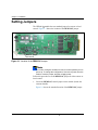
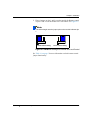
1
Installation and Operation Manual
Selenio 6800™
HFS6801+ HD/SD TV
Video Frame Synchronizer
Edition B
175-000263-00
Delivering the Moment
Publication Information
© 2014 Imagine Communications Corp. Proprietary and Confidential.
Imagine Communications considers this document and its contents to be proprietary and confidential. Except for
making a reasonable number of copies for your own internal use, you may not reproduce this publication, or any part
thereof, in any form, by any method, for any purpose, or in any language other than English without the written consent
of Imagine Communications. All others uses are illegal.
This publication is designed to assist in the use of the product as it exists on the date of publication of this manual, and
may not reflect the product at the current time or an unknown time in the future. This publication does not in any way
warrant description accuracy or guarantee the use for the product to which it refers. Imagine Communications reserves
the right, without notice to make such changes in equipment, design, specifications, components, or documentation as
progress may warrant to improve the performance of the product.
Trademarks
6800+™, ADC™, CCS Navigator™, Channel ONE™, ChannelView™, ClipSync™, Delay™, D Series™, D Series DSX™, Deliver
the Moment™, Delivering the Moment™, FAME™, Farad™, G8™, G Scribe™, HView™, IconMaster™, IconLogo™, IconStation™, IconKey™, InfoCaster™, InfoCaster Creator™, InfoCaster Manager™, InfoCaster Player™, InstantOnline™, Invenio®,
Live Update™, mCAPTURE™, Magellan™, Magellan CCS Navigator™, Magellan Q SEE™, MultiService SDN™, NetPlus™,
NetVX™, NewsForce™, Nexio® G8™, Nexio AMP® ChannelView™, Nexio® Channel ONE™, Nexio® ClipSync™, Nexio®
Delay™, Nexio® Digital Turnaround Processor™, Nexio® Farad™, Nexio® G Scribe™, Nexio® IconKey™, Nexio® IconLogo™,
Nexio® IconMaster™, Nexio® IconStation™, Nexio® InfoCaster™, Nexio® InfoCaster Creator™, Nexio® InfoCaster Manager™, Nexio® InfoCaster Player™, Nexio® InfoCaster Traffic™, Nexio® InstantOnline™, Nexio® mCAPTURE™, Nexio® NewsForce™, Nexio® NXIQ™, Nexio® Playlist™, Nexio® Remote™, Nexio®RTX Net™, Nexio® TitleMotion™, Nexio® TitleOne™,
Nexio® Velocity ESX™, Nexio® Velocity PRX™, Nexio® Velocity XNG™, Nexio® Volt™, OPTO+™, Panacea™, Platinum™,
Playlist™, Predator II GRF™, Predator II GX™, Punctuate™, Remote™, RTX Net™, QuiC™, Q SEE™, SD STAR™, Selenio™,
Selenio 6800+™, SelenioNext™, Selenio X50™, Selenio X85™, Selenio X100™, TitleMotion™, TitleOne™, Velocity ESX™,
Velocity PRX™, Velocity XNG™, Versio™, Videotek® SD STAR™, X50™, and X85™ are trademarks of Imagine Communications or its subsidiaries.
Altitude Express®, Connectus®, Enabling PersonalizedTV®, ICE® Broadcast System, ICE Illustrate®, ICE Q® algorithms, ICEPAC®, Imagine ICE®, Inscriber®, Inscriber® Connectus®, Invenio®, NEO®, Nexio®, Nexio AMP®, PersonalizedTV®, RouterWorks®, Videotek®, Videotek® ASI STAR®, Videotek® GEN STAR®, and Videotek® HD STAR® are registered trademarks of
Imagine Communications or its subsidiaries.
Microsoft® and Windows® are registered trademarks of Microsoft Corporation. HD BNC is a trademark of Amphenol
Corporation. Some products are manufactured under license from Dolby Laboratories. Dolby and the double D symbol
are registered trademarks of Dolby Laboratories. DTS Neural audio products are manufactured under license from DTS
Licensing Limited. DTS and the Symbol are registered trademarks & the DTS Logos are trademarks of DTS, Inc. © 2008
2010 DTS, Inc. All other trademarks and trade names are the property of their respective companies.
Contact Information
Imagine Communications has office locations around the world. For locations and contact information see:
http://www.imaginecommunications.com/contact us/
Support Contact Information
For support contact information see:
▪▪
▪▪
Support Contacts: http://www.imaginecommunications.com/services/technical support/
eCustomer Portal: http://support.imaginecommunications.com
© 2014 Imagine Communications Corp.
Proprietary and Confidential
HFS6801+
HD/SD TV Video Frame
Synchronizer
Installation and Operation Manual
Edition B
April 2007
Contents
Preface
Manual Information .............................................................................. vii
Purpose ........................................................................................... vii
Audience ........................................................................................ vii
Revision History ............................................................................ vii
Writing Conventions ..................................................................... viii
Obtaining Documents ................................................................... viii
Unpacking/Shipping Information .......................................................... ix
Unpacking a Product ....................................................................... ix
Product Servicing ............................................................................ ix
Returning a Product ........................................................................ ix
Restriction on Hazardous Substances (RoHS) Compliance ....................x
Waste from Electrical and Electronic Equipment (WEEE) Compliance xi
Safety .................................................................................................... xii
Safety Terms and Symbols in this Manual .................................... xii
Chapter 1: Introduction
Overview ..................................................................................................1
Product Description ..................................................................................2
General Description ..........................................................................2
Main Features ...................................................................................3
Module Descriptions ................................................................................4
Front Module ....................................................................................4
Back Connectors ...............................................................................6
Signal Flow .......................................................................................7
HFS6801+ Installation and Operation Manual
iii
Contents
Chapter 2: Installation
Overview ................................................................................................. 9
Maximum 6800+ Frame Power Ratings ............................................... 10
Unpacking the Module .......................................................................... 11
Preparing the Product for Installation ............................................ 11
Checking the Packing List ............................................................. 11
Setting Jumpers ..................................................................................... 12
Installing 6800+ Modules ..................................................................... 14
Required Frames and Back Connector Types ................................ 14
Installing and Removing Modules ................................................. 14
Making Connections ............................................................................. 15
Upgrading Module Firmware ................................................................ 16
Upgrading the Firmware ................................................................ 16
Correcting a Failed Upgrading Procedure ..................................... 20
Chapter 3: Operation
Overview ............................................................................................... 23
Operating Notes ..................................................................................... 24
Parameter Availability based on Operating Mode ................................ 25
Changing Parameter Settings ................................................................ 26
Recalling Default Parameter Settings ............................................ 27
Reading Software and Hardware Versions .................................... 27
Setting HFS6801+ Control Parameters ................................................. 28
Cross-Functional Parameter Changes ............................................ 34
LEDs and Alarms .................................................................................. 35
Monitoring LEDs ........................................................................... 35
Module Status LEDs ...................................................................... 37
Alarms ............................................................................................ 38
iv
HFS6801+ Installation and Operation Manual
Contents
Chapter 4: Specifications
Overview ................................................................................................39
Inputs ......................................................................................................40
SDI Video Input ..............................................................................40
Outputs ...................................................................................................41
SDI Video Output ...........................................................................41
Reference Video .............................................................................42
Propagation Delay ...........................................................................42
Power Consumption ...............................................................................43
Operating Temperature ..........................................................................43
Appendix A: Communication and Control
Troubleshooting Tips
Overview ................................................................................................45
General Troubleshooting Steps ..............................................................46
Software Communication and Control Issues ........................................47
+ Pilot Lite Fails to Communicate with Installed Modules ...........47
+ Pilot Lite Does Not Find All Modules in Frame ........................48
+ Pilot Lite or CCS Software Application Not Responding ..........49
+ Pilot Lite Cannot Control a Module Showing
in the Control Window ...................................................................49
+ Pilot Lite Status Bar Reports “Not Ready” .................................49
CCS Software Application or Remote Control Panel Does Not
Communicate with Module ............................................................50
Alarm Query Fails When a Device Reboots ...................................50
Hardware Communication and Control Issues ......................................51
Frames Fail to Communicate with the PC after a Power Failure ...51
Module Does Not Seem to Work ....................................................51
Contacting Customer Service .................................................................51
Index
Keywords ...............................................................................................53
HFS6801+ Installation and Operation Manual
v
Contents
vi
HFS6801+ Installation and Operation Manual
Preface
Manual Information
Purpose
This manual details the features, installation procedures, operational
procedures, and specifications of the HFS6801+ HD / SD TV Video
Frame Synchronizers.
Audience
This manual is written for engineers, technicians, and operators
responsible for the installation, setup, and/or operation of HFS6801+
HD / SD TV Video Frame Synchronizers.
Revision History
Table P-1. Document Revision History
Edition
Date
Revision History
A
August 2005
Initial release
B
April 2007
Addition of firmware upgrade
procedure and minor updates to content
HFS6801+ Installation and Operation Manual
vii
Preface
Writing Conventions
To enhance your understanding, the authors of this manual have
adhered to the following text conventions:
Table P-2. Writing Conventions
Term or
Convention
Description
Bold
Indicates dialog boxes, property sheets, fields, buttons,
check boxes, list boxes, combo boxes, menus, submenus,
windows, lists, and selection names.
Italics
Indicates email addresses, the names of books or
publications, and the first instances of new terms and
specialized words that need emphasis.
CAPS
Indicates a specific key on the keyboard, such as ENTER,
TAB, CTRL, ALT, or DELETE.
Code
Indicates variables or command-line entries, such as a
DOS entry or something you type into a field.
>
Indicates the direction of navigation through a hierarchy
of menus and windows.
hyperlink
Indicates a jump to another location within the electronic
document or elsewhere
Internet
address
Indicates a jump to a Web site or URL
Note
Indicates important information that helps to avoid and
troubleshoot problems.
Obtaining Documents
Product support documents can be viewed or downloaded from our
Web site at www.broadcast.harris.com/leitch (go to Support>
Documentation). Alternatively, contact your Customer Service
representative to request a document.
viii
HFS6801+ Installation and Operation Manual
Preface
Unpacking/Shipping Information
Unpacking a Product
This product was carefully inspected, tested, and calibrated before
shipment to ensure years of stable and trouble-free service.
1. Check equipment for any visible damage that may have occurred
during transit.
2. Confirm that you have received all items listed on the packing list.
3. Contact your dealer if any item on the packing list is missing.
4. Contact the carrier if any item is damaged.
5. Remove all packaging material from the product and its associated
components before you install the unit.
Keep at least one set of original packaging, in the event that you need to
return a product for servicing.
Product Servicing
Except for firmware upgrades, HSFS6800+ modules are not designed
for field servicing. All hardware upgrades, modifications, or repairs
require you to return the modules to the Customer Service center.
Returning a Product
In the unlikely event that your product fails to operate properly, please
contact Customer Service to obtain a Return Authorization (RA)
number, then send the unit back for servicing.
Keep at least one set of original packaging in the event that a product
needs to be returned for service. If the original package is not available,
you can supply your own packaging as long as it meets the following
criteria:
•
The packaging must be able to withstand the product’s weight.
•
The product must be held rigid within the packaging.
•
There must be at least 2 in. (5 cm) of space between the product and
the container.
•
The corners of the product must be protected.
Ship products back to us for servicing prepaid and, if possible, in the
original packaging material. If the product is still within the warranty
period, we will return the product prepaid after servicing.
HFS6801+ Installation and Operation Manual
ix
Preface
Restriction on Hazardous Substances (RoHS)
Compliance
Directive 2002/95/EC—commonly known as the European Union (EU)
Restriction on Hazardous Substances (RoHS)—sets limits on the use of
certain substances found in electrical and electronic equipment. The
intent of this legislation is to reduce the amount of hazardous chemicals
that may leach out of landfill sites or otherwise contaminate the
environment during end-of-life recycling. The Directive, which took
effect on July 1, 2006, refers to the following hazardous substances:
•
Lead (Pb)
•
Mercury (Hg)
•
Cadmium (Cd)
•
Hexavalent Chromium (Cr-V1)
•
Polybrominated Biphenyls (PBB)
•
Polybrominated Diphenyl Ethers (PBDE)
According to this EU Directive, all products sold in the European Union
will be fully RoHS-compliant and “lead-free.” (See our Web site,
www.broadcast.harris.com/leitch, for more information on dates and
deadlines for compliance.) Spare parts supplied for the repair and
upgrade of equipment sold before July 1, 2006 are exempt from the
legislation. Equipment that complies with the EU directive will be
marked with a RoHS-compliant emblem, as shown in Figure P-1.
Figure P-1. RoHS Compliance Emblem
x
HFS6801+ Installation and Operation Manual
Preface
Waste from Electrical and Electronic
Equipment (WEEE) Compliance
The European Union (EU) Directive 2002/96/EC on Waste from
Electrical and Electronic Equipment (WEEE) deals with the collection,
treatment, recovery, and recycling of electrical and electronic waste
products. The objective of the WEEE Directive is to assign the
responsibility for the disposal of associated hazardous waste to either
the producers or users of these products. As of August 13, 2005, the
producers or users of these products were required to recycle electrical
and electronic equipment at end of its useful life, and may not dispose
of the equipment in landfills or by using other unapproved methods.
(Some EU member states may have different deadlines.)
In accordance with this EU Directive, companies selling electric or
electronic devices in the EU will affix labels indicating that such
products must be properly recycled. (See our Web site,
www.broadcast.harris.com/leitch, for more information on dates and
deadlines for compliance.) Contact your local sales representative for
information on returning these products for recycling. Equipment that
complies with the EU directive will be marked with a WEEE-compliant
emblem, as shown in Figure P-2.
Figure P-2. WEEE Compliance Emblem
HFS6801+ Installation and Operation Manual
xi
Preface
Safety
Carefully review all safety precautions to avoid injury and prevent
damage to this product or any products connected to it. If this product is
rack-mountable, it should be mounted in an appropriate rack using the
rack-mounting positions and rear support guides provided. It is
recommended that each frame be connected to a separate electrical
circuit for protection against circuit overloading. If this product relies
on forced air cooling, it is recommended that all obstructions to the air
flow be removed prior to mounting the frame in the rack.
If this product has a provision for external earth grounding, it is
recommended that the frame be grounded to earth via the protective
earth ground on the rear panel.
IMPORTANT! Only qualified personnel should perform service
procedures.
Safety Terms and Symbols in this Manual
WARNING
Statements identifying conditions or
practices that may result in personal injury
or loss of life. High voltage is present.
CAUTION
Statements identifying conditions or
practices that can result in damage to the
equipment or other property.
xii
HFS6801+ Installation and Operation Manual
Chapter 1
Introduction
Overview
The HFS6801+ is an HD and SD TV processing module capable of
retiming an I/O signal to a local station clock and allowing the clean
processing of all synchronized signals. The module provides video
frame synchronization and delay for HD and SD TV signals, and
picture control through a video-processing amplifier.
The following topics are described in this chapter:
•
“Product Description” on page 2
•
“Module Descriptions” on page 4
•
“Signal Flow” on page 7
HFS6801+ Installation and Operation Manual
1
Chapter 1: Introduction
Product Description
General Description
The HFS6801+ HD and SD TV Video Frame Synchronizer module
provides a SDI digital input, two active reclocked SDI outputs, four
synchronized SDI outputs, and a genlock reference video input. A
special output provides hot switch and I/O delay signals for tracking
audio processing.
The HFS6801+ module’s reference input (located on the back
connector) and the 6800+ frame’s genlock connector both provide a
reference signal.
This module can be controlled locally (via card edge) or controlled and
monitored remotely with control software applications such as
+Pilot Lite™, CCS™ Pilot™, and CCS Navigator™, or CCS-compliant
remote control panels and other products.
The back connectors for HFS6801+ requires two frame slots within an
FR6802+ frame (there is no backward-compatibility provided for use
with 6800/7000 series frames).
2
HFS6801+ Installation and Operation Manual
Chapter 1: Introduction
Main Features
Important HFS6801+ features include the following:
•
•
•
Inputs:
•
One serial digital SMPTE 292M/SMPTE 259M SDI input
•
Genlock (composite or Tri-Level sync)
Outputs:
•
Two serial digital SMPTE 292M/SMPTE 259M SDI reclocked
outputs
•
Four synchronized serial digital SMPTE 292M/SMPTE 259M
SDI reclocked outputs
•
One DATA I/O signal for tracking audio processing
Capability for operating the following video standards:
•
1080i (interlaced), 25/29.97/30 Hz
•
1080p (progressive), 23.98/24/25/29.97/30 Hz
•
720p (progressive), 50/59.94/60 Hz
•
Standard definition 525/625
•
Auto-detect or user-forced input video standard
•
10-bit video processing
•
Digital equalization (supports Belden 8281 and newer, thin coax
cables like Alcatel SD02)
•
VANC and HANC sample passing capability
•
Clean handling of hot switch on input
•
Up to 8 frames less 2 lines of video delay for 1080i/1080p
standards, 16 frames less 2 lines for 720p standards, and 1 frame for
525/625 standards
•
Pass, black, and freeze loss of video modes
•
Video processing amplifier with luminance gain, luminance offset,
and chrominance gain controls
•
Shadowed / restored parameter settings when switching video
standards
•
Card-edge control
•
Serial and Ethernet remote control and monitoring
HFS6801+ Installation and Operation Manual
3
Chapter 1: Introduction
Module Descriptions
Front Module
Figure 1-1 is a generic top-front view of a typical 6800+ module and
shows the general location of standard LEDs, controls, and jumpers.
The number of Control and Monitoring LEDs on 6800+ modules
varies.
Remote/local
control
jumper
Module Mode select Navigation Control
LEDs
status rotary
toggle
LEDs
switch
switch
Monitoring
LEDs
Extractor
handle
Figure 1-1. Typical 6800+ Module
Table 1-1 on page 5 briefly describes generic 6800+ LEDs, switches,
and jumpers. See “Chapter 3: Operation” for more information on
specific HFS6801+ module controls, LEDs, and jumpers.
4
HFS6801+ Installation and Operation Manual
Chapter 1: Introduction
Table 1-1. Generic 6800+ Module Features
Feature
Description
Module status
LEDs
Various color and lighting combinations of these LEDs
indicate the module state. See “Monitoring LEDs” on
page 35 for more information.
Mode select
rotary switch
This switch selects between various control and
feedback parameters.
Navigation
toggle switch
This switch navigates up and down through the available
control parameters:
• Down: Moves down through the parameters
• Up: Moves up through the parameters
Control LEDs
Various lighting combinations of these Control LEDs
(sometimes referred to as “Bank Select LEDs”) indicate
the currently selected bank. See Table 3-2 “Selected
Bank as Indicated by Control LEDs” for more
information.
Monitoring
LEDs
Each 6800+ module has a number of LEDs assigned to
indicate varying states/functions. See “Monitoring
LEDs” on page 35 for a description of these LEDs.
Local/remote
control jumper
• Local: Locks out external control panels and allows
card-edge control only; limits the functionality of
remote software applications to monitoring
• Remote: Allows remote or local (card-edge)
configuration, operation, and monitoring of the
HFS6801+
HFS6801+ Installation and Operation Manual
5
Chapter 1: Introduction
Back Connectors
Figure 1-2 shows the double-slot back connector used by the
HFS6801+ module when installed in an FR6802+XF frame.
AUX IN
Auxiliary input
SDI video in
SDI IN
1
2
SDI video
outputs
SDI
OUT
3
Analog
reference input
4
GENLOCK
5
DATA I/O
Audio/video
timing output
6
SDI
OUT/
RCLK
SDI video
outputs
SDI5 and SDI6
outputs are
reclocked
Figure 1-2. HFS6801+ Back Connector
6
HFS6801+ Installation and Operation Manual
Chapter 1: Introduction
Signal Flow
Figure 1-3 shows the basic signal flow of the HFS6801+ modules.
Re-clocked
SDI
outputs
SDI input
EQ/
reclock
Frame sync/
proc amp
Four
SDI
outputs
DATA I/O
(audio
tracking)
Reference inputs
Module
Genlock
Frame
CCS control/
monitor port
Figure 1-3. HFS6801+ Signal Flow Diagram
HFS6801+ Installation and Operation Manual
7
Chapter 1: Introduction
8
HFS6801+ Installation and Operation Manual
Chapter 2
Installation
Overview
This chapter describes the HFS6801+ installation process, including the
following topics:
•
“Maximum 6800+ Frame Power Ratings” on page 10
•
“Unpacking the Module” on page 11
•
“Setting Jumpers” on page 12
•
“Installing 6800+ Modules” on page 14
•
“Making Connections” on page 15
•
“Upgrading Module Firmware” on page 16
See the FR6802+ Frame Installation and Operation Manual for
information about installing and operating an FR6802+XF frame and
its components.
Caution
Before installing this product, read the 6800+ Series Safety
Instructions and Standards Manual shipped with every FR6802+
Frame Installation and Operation Manual or downloadable from our
Web site at www.broadcast.harris.com/leitch. This safety manual
contains important information about the safe installation and
operation of 6800+ series products.
HFS6801+ Installation and Operation Manual
9
Chapter 2: Installation
Maximum 6800+ Frame Power Ratings
The power consumption for a HFS6801+ module is 7 W from the
positive supply and 0.3 W from the negative supply.
Table 2-1 describes the maximum allowable power ratings for 6800+
frames. Note the given maximums before installing any 6800+ modules
in your frame.
Table 2-1. Maximum Power Ratings for 6800+ Frames
Max. Frame
Power
Dissipation
Number
Max. Power
of Usable Dissipation
Slots
Per Slot
FR6802+XF
(frame with AC power
supply)
120 W
20
6W
FR6802+XF48
(frame with DC power
supply)
105 W
20
5.25 W
FR6802+QXF frame
(with AC or DC power
supply)
120W
20
6W
6800+ Frame
Type
10
HFS6801+ Installation and Operation Manual
Chapter 2: Installation
Unpacking the Module
Preparing the Product for Installation
Before you install the HFS6801+, perform the following:
•
Check the equipment for any visible damage that may have
occurred during transit.
•
Confirm receipt of all items on the packing list. See “Checking the
Packing List” for more information.
•
Remove the anti-static shipping pouch, if present, and all other
packaging material.
Note
Contact your Customer Service representative if parts are missing
or damaged.
•
Retain the original packaging materials for possible re-use.
See “Unpacking/Shipping Information” on page ix for information
about returning a product for servicing.
Checking the Packing List
Table 2-2. Available Product Packages
Ordered Product
Content Description
HFS6801+
• One front module
• One HFS6801+ HD / SD TV Video
Frame Synchronizers Installation and
Operation Manual
HFS6801+D
• One front module
• One back connector
• One HFS6801+ HD / SD TV Video
Frame Synchronizers Installation and
Operation Manual
HFS6801+DR
HFS6801+ Installation and Operation Manual
One back connector
11
Chapter 2: Installation
Setting Jumpers
The HFS6801+ module has one standard jumper for remote or local
control. Figure 2-1 shows the location of the REM/LOC jumper.
REM/LOC jumper
Remote/local
Figure 2-1. Location of the REM/LOC Jumper
Note
You need to configure modules for local or remote operation prior to
power-up. To change the configuration, first remove power from the
module, reset the jumper, and then reapply power.
Follow this procedure to set the REM/LOC jumper for either remote or
local control:
1. Locate the REM/LOC control jumper on the module (beside the
extractor handle).
Figure 2-1 shows the standard location of the REM/LOC jumper.
12
HFS6801+ Installation and Operation Manual
Chapter 2: Installation
2. Place a jumper on pins 1 and 2 to set the module for Remote control
or pins 2 and 3 to set the module for Local control. See Figure 2-2.
Note
The white triangle near the jumper pins on the module indicates pin
1.
1
2
3
Remote control setting
1
2
3
Local control setting
Figure 2-2. REM/LOC Settings for Remote and Local Control
See Table 1-1 on page 5 for more information on local/remote control
jumper functionality.
HFS6801+ Installation and Operation Manual
13
Chapter 2: Installation
Installing 6800+ Modules
Required Frames and Back Connector Types
The HFS6801+ modules have double-width back connectors that can
be installed in an FR6802+XF or FR6802+QXF frame. HFS6801+
modules cannot be installed in a FR6802+DM frame, a FR6800/7000
frame, or a frame without fans.
See the FR6802+ Frame Installation and Operation Manual for details
on installing back connectors in an FR6802+ frame.
A FR6802+RM (Rear Support Extension Rails for 6800+ series
frames) option is recommended for the HFS6801+ modules. See your
FR6802+ Frame Installation and Operation Manual for installation
instructions.
Installing and Removing Modules
These modules require no specialized installation or removal
procedures. However, if installing both front and rear modules, ensure
that the back module is installed first before plugging in the front
module.
Caution
Before removing, inserting, or replacing a back module in your
frame, you must remove power from the frame. Failure to power
down the frame could result in damage to the frame, modules, or
power supply.
When removing both the front and rear modules, ensure that the front
module is unplugged from the frame first, before removing the rear
module.
14
•
See the FR6802+ Frame Installation and Operation Manual for
information about installing and operating an FR6802+ frame and
its components.
•
See the 6800+ Safety Instructions and Standards Manual for
important information about safely installing your module.
HFS6801+ Installation and Operation Manual
Chapter 2: Installation
Making Connections
Once you have installed the HFS6801+ module, you can connect it to
the appropriate input and outputs.
Note that the data I/O output provides reference signals for 6800+
audio tracking modules. It can drive up to four chained audio modules
over coaxial cable up to 985 ft (300 m) long. If you wish to connect to
more than one audio module, you will achieve the best results if yoou
use T-connectors.
See the applicable audio module Installation and Operation manual for
complete connection instructions.
HFS6801+ Installation and Operation Manual
15
Chapter 2: Installation
Upgrading Module Firmware
Firmware upgrading is a routine procedure that you must perform to
install newer versions of software on 6800+ modules. CCS Pilot,
CoPilot, or Navigator software version 3.1.1 or later is required for this
procedure. The frame must contain or be connected to another frame
that contains an ICE6800+ or a 6800+Eth module.
Note
Firmware for the HFS6801+ must be updated in Boot Loader
mode.
In the unlikely event that the upgrade fails (because of such situations
as network interruptions, power failures, etc.), the module may not
respond to controls and will appear to be non-functional. In that event,
follow the procedures described in “Correcting a Failed Upgrading
Procedure” on page 20.
Upgrading the Firmware
You can upgrade your 6800+ module’s firmware using the Software
Upgrade tool. This tool is included with CCS Pilot, Co-Pilot, or
Navigator software version 3.1.1 or later.
Caution
The File Transfer tab is not meant to be used for firmware
upgrades. For best results, use the Software Uprade tool to
upgrade module firmware.
To upgrade your module’s firmware, follow these steps:
1. Download the most recent appropriate upgrade package from our
Web site or from your CD-ROM.
16
HFS6801+ Installation and Operation Manual
Chapter 2: Installation
2. Remove the module from the 6800+ frame.
Mode select rotary Navigation toggle
(hex) switch
switch
Figure 2-3. Buttons on a Typical Card Edge
3. Set the Hex switch to F.
4. While pressing the Navigation toggle switch down, reinsert the
module into the frame and then release the Navigation toggle
switch.
5. Perform a Discovery operation to discover the module, as described
in “Discovering a DAV6800+ Module” on page 30.
Information about discovering modules can also be found in
your CCS software application manual or online help. (If you
cannot discover the device, see “Manually Adding a Device to
the Discovery or Network Folder” on page 21.)
HFS6801+ Installation and Operation Manual
17
Chapter 2: Installation
6. From the Tools menu, select Software Upgrade.
The Software Upgrade window opens or is brought to the
foreground.
Version Info lists
the firmware version
currently installed on
the module.
Package Info
includes a list of the
components
contained in the ZIP
file.
Figure 2-4. Software Upgrade Tool’s New Transfer Tab
7. On the New Transfer tab, click Add.
The Device Selection dialog opens.
8. Select one or more devices, and then click OK to close the Add
Device dialog box.
You can only add one unit from each IP address. All items in a
frame have the same IP address.
The selected devices appear in the table under Device Name. These
devices will receive the same upgrade package.
9. Before proceeding with the firmware upgrade, you can—
•
Highlight the module’s position in the Navigation window by
clicking Find Device.
•
View the firmware version currently installed on the module by
clicking Version Info.
10. Press Browse... to select the software upgrade package (ZIP file).
A standard Windows File Selection dialog opens.
18
HFS6801+ Installation and Operation Manual
Chapter 2: Installation
11. Choose the upgrade ZIP file on a local or network drive.
The selected file’s path name is displayed in the edit box to the left
of the Browse… button.
The extraction process on the ZIP file is handled as part of the
upgrade process. You do not need to extract the files yourself.
You can view the contents of the ZIP file by clicking Package
Info.
12. Press Submit Transfer...
A dialog box opens, requesting confirmation that you want to
proceed with the request. If you have multiple devices selected,
multiple transfer tasks are submitted—one per device.
The transfer now progresses. You may minimize the Software
Upgrade window, continue with other tasks, or switch to the
Progress tab to view the status of the transfers.
Closing the Software Upgrade window does not effect any of
the transfer processes that may be running in the background.
If you try to log off or exit the CCS software while a transfer is
underway, a notification window will alert you that processes
are still active and will ask if you want to terminate these
processes.
13. Click on the Log tab and look at the Progress column to ensure that
all files have correctly updated.
14. When the update is complete, reboot the module by manually
pulling it out and then pushing it back into its slot in the frame.
You cannot click Reboot Device to reboot 6800+ modules that
must be upgraded in Boot Loader mode.
Your upgrade procedure is complete.
If for some reason the upgrade fails, the module may not respond to
controls and will appear to be non-functional. In that event, follow the
procedures described in “Correcting a Failed Upgrading Procedure” on
page 20.
HFS6801+ Installation and Operation Manual
19
Chapter 2: Installation
Correcting a Failed Upgrading Procedure
Firmware upgrades may fail in the event of network interruptions,
power failures, or if the wrong upgrade package was transferred to the
module. These problems can be corrected by upgrading the firmware
while the module is in Boot Loader mode. The upgrade won't work
unless you put the module in Boot Loader mode.
Note
If you have not already downloaded the most recent appropriate
upgrade package from our Web site or from your CD-ROM, do so
now.
Putting the Module in Boot Loader Mode
Follow these steps to put your the module in Boot Loader mode:
1. Remove the affected module from the 6800+ frame.
Hex switch (mode
select rotary switch)
Navigation toggle
switch
Figure 2-5. Buttons on a Typical Card Edge
2. Set the hex switch to F.
3. While pressing the Navigation toggle switch down, reinsert the
module into the frame.
If your device is listed in the Discovery or Network folder, you can
continue the firmware upgrade as described in “Upgrading the
Firmware” begining with step 6 on page 18. If not, you must manually
add the device to the Discovery or Network folder. To do this, see the
next section.
20
HFS6801+ Installation and Operation Manual
Chapter 2: Installation
Manually Adding a Device to the Discovery or Network Folder
If your device is not listed in the Discovery or Network folder, you
must manually add it to these folders. After you add the device, you can
use the Software Upgrade dialog box to continue with the module
firmware upgrade.
To manually add a device to the Discovery or Network folder, follow
these steps:
1. Enter Build mode, and then drag or copy and paste the module’s
device icon from the Catalog folder into the Network or Discovery
folder.
2. Right-click the device icon, and then select Properties.
3. On the Device tab of the Navigation Properties box, enter the IP
address of the frame that holds the module. (See Figure 2-6.)
Enter frame IP address here
Must be set to 1
Do not make changes in
this field
Frame number=0
Slot number=17
Figure 2-6. Navigation Properties Box
Caution
If you make changes in the last field (located above and to the right
of the Set Default button), you may lose your connection to the
module. If this happens, you will need to rediscover the module.
HFS6801+ Installation and Operation Manual
21
Chapter 2: Installation
4. In the third field, enter
1.0.[slotnumber]
(where, for example, 1.0.5 would refer to the module in slot 5 of the
frame number 0).
5. Close the window.
6. You can now continue your firmware upgrade as described in
“Upgrading the Firmware” begining with step 6 on page 18.
22
HFS6801+ Installation and Operation Manual
Chapter 3
Operation
Overview
This chapter describes how to operate the HFS6801+ using card-edge
controls only. See the following documents for information on how to
operate this product remotely:
•
+Pilot Lite User Manual for serial control interface
•
CCS Pilot, CoPilot, Navigator, or RCP-CCS-1U Remote Control
Panel manual for Ethernet control interface
The following topics are discussed in this chapter:
•
“Operating Notes” on page 24
•
“Parameter Availability based on Operating Mode” on page 25
•
“Changing Parameter Settings” on page 26
•
“Setting HFS6801+ Control Parameters” on page 28
•
“LEDs and Alarms” on page 35
HFS6801+ Installation and Operation Manual23
Chapter 3: Operation
Operating Notes
When setting the control parameters on the HFS6801+, observe the
following:
•
If you make changes to certain parameters, other related parameters
may also be affected. See the section “Setting HFS6801+ Control
Parameters” on page 28 for more information.
•
When you change a parameter, the effect is immediate. However,
the module requires up to 20 seconds to save the latest change.
After 20 seconds, the new settings are saved and will be restored if
the module loses power and must be restarted.
•
When you set the Factory Recall parameter to Yes, the module
takes several seconds to reset all of the parameters to their default
settings.
•
For proper operation, the output HD standard frame rate should
match or be double the reference standard frame rate.
•
For best results, terminate any unused coaxial output connectors
with a 75Ω terminator.
See “Parameter Availability based on Operating Mode” on page 25 for
more operational information.
24HFS6801+ Installation and Operation Manual
Chapter 3: Operation
Parameter Availability based on Operating
Mode
Depending on whether the operating mode is HD or SD, some
parameters will be enabled and some disabled. The HD parameters will
apply when SdiStdSet is set to one of the HD operating modes, or when
the SdiStdSet is set to Auto and SdiStdFdbk is one of the HD operating
modes. The SD parameters will apply when SdiStdSet is set to either
SD 525 or SD 625, or the SdiStdSet is set to Auto and SdiStdFdbk is SD
525 or SD 625.
Note
The parameter Hue is only available in SD 525 mode.
Table 3-1. Parameter Availability Based on Operating Mode
Condition
Enabled
Parameters
Disabled
Parameters
HD Operating Mode:
• Y CRC Error Counter
• Hue
• 1080i/30
• Y CRC Err Cnt Clear
• EDH Present
• 1080i/29.97
• C CRC Error Counter
• EDH Error Count
• 1080i/25
• C CRC Err Cnt Clear
• EDH Error Clear
• In Field Detection
• 1080p/30
• 1080p/29.97
• 1080p/25
• 1080p/24
• 1080p/23.98
• 720p/60
• 720p/59.94
• 720p/50
SDI Operating Mode:
• Hue
• Y CRC Error Counter
• SD 525
• EDH Present
• Y CRC Err Cnt Clear
• SD 625
• EDH Error Count
• C CRC Error Counter
• EDH Error Clear
• C CRC Err Cnt Clear
• In Field Detection
HFS6801+ Installation and Operation Manual25
Chapter 3: Operation
Changing Parameter Settings
Note
For best results, use the available 6800+ software control options
(serial/local or Ethernet/remote) to aid in viewing, setting, and
confirming parameter values.
Follow these steps to change the HFS6801+ parameter settings:
1. Rotate the mode select rotary switch (hex switch) to “0.”
2. Once the hex switch is set to “0,” toggle the navigation switch up or
down to select a bank.
View the two control LEDs next to the navigation toggle switch to
see which bank is currently selected.
Table 3-2. Selected Bank as Indicated by Control LEDs
Bank Select LED 1
Bank Select LED 2
Bank Select LED 3
(first top LED)
(second top LED)
(third top LED)
Off
Off
Off
0
On
Off
Off
1
Off
On
Off
2
On
On
Off
3
Off
Off
On
4
On
Off
On
5
Off
On
On
6
On
On
On
7
Bank Number
See Table 3-3 on page 29 to view the various banks, hex switch
positions, and corresponding parameter options and values.
3. Rotate the hex switch to the parameter number (1 to 9) or letter
(A to F) of the option you want to set.
4. Toggle the navigation switch to select and set the value of the
chosen parameter.
26HFS6801+ Installation and Operation Manual
Chapter 3: Operation
5. Rotate the hex switch to another parameter number/letter in the
current bank, and then repeat step 4.
or
Rotate the hex switch to “0” again to select a different bank, and
then repeat steps 3 and 4.
Recalling Default Parameter Settings
Table 3-3 on page 29 describes all of the parameter settings for the
HFS6801+ modules, including the original factory defaults. To return
this module to its default settings, you can either reset each parameter
individually or do a global recall following this procedure:
1. Rotate the hex switch to “0.”
2. Toggle the navigation switch to the bank number “0.”
Use the control LEDs to verify which bank you have selected, or
use an available 6800+ software control option (serial/local or
Ethernet/remote) to aid in confirming your bank selection.
3. Rotate the hex switch to the global recall parameter “F.”
4. Toggle the navigation switch to “On.”
Use an available 6800+ software control option to aid in viewing,
setting, and confirming the parameter value.
Reading Software and Hardware Versions
The current software version of your HFS6801+ modules can only be
viewed using a CCS-enabled control panel or a CCS software
application, such as Pilot or +Pilot Lite. See your RCP-CCS-1U
Installation and Operation Manual, CCS software application user
manual, or CCS software application online help for information on
viewing software and hardware version numbers.
HFS6801+ Installation and Operation Manual27
Chapter 3: Operation
Setting HFS6801+ Control Parameters
Table 3-3 lists all of the available parameters and options for the
HFS6801+. All parameters clip unless otherwise indicated.
Note
The sequence of options listed in the Options column mirrors the
sequence achieved when you move the Navigation Toggle switch
up.
The On/Off combinations of the control LEDs on the card-edge indicate
the active bank number. See “Changing Parameter Settings” on page 26
for more information.
Legend
Bold option = Indicates that this is the default setting for the parameter
[RO] = Indicates that parameters are read-only/feedback, and cannot be
used to select controls
1(superscript digit)
= Indicates that there is a footnote for this parameter
entry, found at the end of the tables
28HFS6801+ Installation and Operation Manual
Chapter 3: Operation
Table 3-3. Parameter Options
Bank,
Rotary
Parameter Name Function
Switch
Options
Bank 0
0, 1
SDI IP Video Std Set
Selects the SDI input video signal standard
• SD 525
• SD 625
• 1080I 30
• 1080I 29.97
• 1080I 25
• 1080P 30
• 1080P 29.97
• 1080P 25
• 1080P 24
• 1080P 23.98
• 720P 60
• 720P 59.94
0, 2
Y CRC Err Cnt Clear
Clears the luminance CRC error counter
• 720P 50
• On
0, 3
C CRC Err Cnt Clear
Clears the chrominance CRC error counter
• Off
• On
0, 4
EDH Error Cnt Clear
Clears EDH error counter
• Off
• On
0, 5
Frame Sync Mode
0, 6
Force Freeze
Selects the operational mode for the frame
synchronizer
Forces the output video to freeze
0, 7
Freeze Type
Selects the type of manual video freeze
• Off
• Sync Mode
• Delay Mode
• Off
• On
• Field 1
• Field 2
0, 8
Video OP Mode
Selects the output video mode when the
input video is disrupted
• Frame
• Pass
• Black
• Freeze
HFS6801+ Installation and Operation Manual29
Chapter 3: Operation
Table 3-3. Parameter Options (Continued)
Bank,
Rotary
Parameter Name Function
Switch
0, 9
Vertical Phase *
Adjusts the vertical timing
Options
• 0 to 1124 Ln
• 0 to 524 Ln
• 0 to 624 Ln
• 0 to 749 Ln
0, A
Horizontal Phase *
Adjusts the horizontal timing
(see “Cross-Functional
Parameter Changes” on
page 34)
• 0.0 to 35.542 µs
• 0.0 to 22.209 µs
• 0.0 to 22.231 µs
• 0.0 to 26.653 µs
• 0.0 to 29.616 µs
• 0.0 to 29.646 µs
• 0.0 to 37.024 µs
• 0.0 to 37.061 µs
• 0.0 to 63.519 µs
• 0.0 to 63.963 µs
0, B
Delay Range *
Adjusts the amount of frame delay
(see cross-functional
parameter changes
table)
• 0 to 7 frm
• 0 to 1 frm
• 0 to 15 frm
0, C
Y Offset
Adjusts offset for the Y channel
0, D
Cb Offset
Adjusts offset for the Cb channel
0, E
Cr Offset
Adjusts offset for the Cr channel
0, F
Factory Recall
Recalls the factory settings
(see “Cross-Functional
Parameter Changes” on
page 34)
-100.685 to 100.685 mV
(0.0)
-100.685 to 100.685 mV
(0.0)
-100.685 to 100.685 mV
(0.0)
• Off
• On
Bank 1
30HFS6801+ Installation and Operation Manual
Chapter 3: Operation
Table 3-3. Parameter Options (Continued)
Bank,
Rotary
Parameter Name Function
Switch
1, 1
Y Gain
Adjusts gain to the luminance channel
1, 2
Cb Gain
1, 3
Cr Gain
1, 4
Black Clip Level
Adjusts gain to the Cb color difference
component
Adjusts gain to the Cr color difference
component
Sets the black clip level
1, 5
Black Clip
Controls the activation of Black Clip
1, 6
White Clip Level
Sets the white clipping level
1, 7
White Clip
Controls the activation of White Clip
1, 8
Hue
1, 9
Test Signal Enable
1, A
GL Lock Source
1, B
In Field Detection
Adjusts the hue of the incoming digital
video signal
Controls the activation of the internal test
signal generator
Selects the reference source for the on-board
genlock circuit
Selects the input field detection by either
V-bit or F-bit
Remote Control Only
HFS6801+ Installation and Operation Manual31
Options
-3.0 to 3.0 dB
(0.0)
-3.0 to 3.0 dB
(0.0)
-3.0 to 3.0 dB
(0.0)
-47.9 to 47.9 mV
(0.0)
• Off
• On
636.87 to 763.13 mV
(700.0)
• Off
• On
-180 to 180 °
(0)
• Off
• On
• Card Ref
• Frame Ref
• V-bit
• F-bit
Chapter 3: Operation
Table 3-3. Parameter Options (Continued)
Bank,
Rotary
Parameter Name Function
Switch
[RO]
SDI IP Video Std Fb
Reports the detected HD SDI input video
signal standard
Options
• Unknown
• 1080P 25
• 720P 59.94
• 720P 60
• 1080P 23.98
• 1080P 24
• 1080P 29.97
• 1080P 30
• 1080I 25
• 1035I 29.97
• 1035I 30
• 1080I 25 (295M)
• 1080I 29.97
• 1080I 30
• SD 525
• SD 625
• 720P 50
• 1080PsF 23.98
• 1080PsF 24
• 720P 29.97
• 720P 30
• 720P 25
• 720P 23.98
• 720P 24
• 1080PsF 29.97
[RO]
[RO]
[RO]
SDI IP Video Present
Reports the presence of the HD SDI input
video signal
Y CRC Error Counter Reports the number of occurred luminance
CRC errors
C CRC Error Counter Reports the number of occurred
chrominance CRC errors
32HFS6801+ Installation and Operation Manual
• 1080PsF 30
• No
• Yes
0 to 16777215
0 to 16777215
Chapter 3: Operation
Table 3-3. Parameter Options (Continued)
Bank,
Rotary
Parameter Name Function
Switch
[RO]
EDH Present
[RO]
[RO]
EDH Error Count
Vieo Frozen
[RO]
GL Video Present
[RO]
GL Video Locked
[RO]
Genlock Std
Feedback
Reports the presence of EDH in the input
SDI signal
Reports the number of occurred EDH errors
Reports the output video frozen status
Reports the presence of the video signal
from the external reference source
Reports the locked status of the external
reference signal
Reports the detected Genlock standard
Options
• No
• Yes
0 to 32767
• No
• Yes
• No
• Yes
• No
• Yes
• Unknown
• 1080P 25
• 720P 59.94
• 720P 60
• 1080P 23.98
• 1080P 24
• 1080P 29.97
• 1080P 30
• 1080I 25
• 1080I 29.97
• 1080I 30
• SD525
• SD625
• 720P 50
• 1080Psf 23.98
• 1080Psf 24
Notes:
1. The frame rate for both input video and reference video must match.
HFS6801+ Installation and Operation Manual33
Chapter 3: Operation
Cross-Functional Parameter Changes
When you configure certain parameters, you force a change in other
associated parameters. The following table describes those parameters
affected by other option selections.
An example of a cross-functional change concerns the Horizontal Phase
and Vertical Phase parameters. When the Horizontal Phase is controlled
from the card edge, any wrap around of the values will cause a
corresponding increment or decrement of the Vertical Phase value.
Table 3-4. Parameters That Are Affected by Input Standard and Frame Rate
Parameter
SDI Input Video Standard and Frame Rate
Name
Vertical
Phase
SD 525
SD 625
1080I/30, 29.97, and
25
1080P/30, 29.97, 25,
24 and 23.98
720P/60, 59.94, and
50
0 to 524
lines
0 to 624
lines
0 to 1124 lines
0 to 1124 lines
0 to 749 lines
0 to
0 to
63.519 µs 63.963 µs
30: 0 to 29.616 µs
30: 0 to 29.616 µs
29.97: 0 to 29.646 µs 29.97: 0 to 29.646 µs
25: 0 to 35.542 µs
25: 0 to 35.542 µs
24: 0 to 37.024 µs
23.98: 0 to 37.061 µs
60: 0 to 22.209 µs
59.94: 0 to 22.231 µs
50: 0 to 26.653 µs
Delay Range
0 to 1
frm1
0 to 1
frm1
0 to 7 frm
0 to 7 frm
0 to 15 frm
• Field 1
• Field 2
• Frame
• Field 1
• Field 2
• Frame
• Field 1
• Field 2
• Frame
Frame
Frame
Freeze Type
Horizontal
Phase
1 In SD mode (SD 525 and SD 625), Vertical Phase and Horizontal Phase are disabled when Delay
Range equals 1.
34HFS6801+ Installation and Operation Manual
Chapter 3: Operation
LEDs and Alarms
Monitoring LEDs
The HFS6801+ has 9 monitoring LEDs that serve as a quick
monitoring reference. Figure 3-1 shows the general location of the
monitoring LEDs on a generic 6800+ module. The table that follows,
Table 3-5, describes each LED in more detail.
Module status LEDs
Monitoring LEDs
Figure 3-1. Location of Card-Edge LEDs
The 9 monitoring LEDs on the card-edge of HFS6801+ modules are
identified in Figure 3-1 (left to right).
Table 3-5. Monitoring LEDs
LED
Description
Color Indication
Auto
Indicates if auto detection of
the input video signal is
activated
• GREEN: Auto
detect enabled
Indicates if a 720P video
source is present
• GREEN: 720P video
present
720P
• OFF: Auto detect
disabled
• OFF: 720P video not
present
HFS6801+ Installation and Operation Manual35
Chapter 3: Operation
Table 3-5. Monitoring LEDs (Continued)
LED
Description
Color Indication
1080I
Indicates if a 1080I video
source is present
• GREEN: 1080I
video present
• OFF: 1080I video
not present
1035I
Indicates if a 1035I video
source is present
• GREEN: 1035I
video present
• OFF: 1035I video
not present
1080P/sF
Indicates if a 1080P/sF video
source is present
• GREEN: 1080P/sF
video present
• OFF: 1080P/sF
video not present
525
Indicates if a 525 video source
is present
• GREEN: 525 video
present
• OFF: 525 video not
present
625
Indicates if a 625 video source
is present
• GREEN: 625 video
present
• OFF: 625 video not
present
Reference Present Indicates the presence of the
reference signal either from
the back module or internally
from the NEO frame
• GREEN: Genlock
present
Freeze
• AMBER: Output
video frozen
36HFS6801+ Installation and Operation Manual
Illuminates if the frame
synchronizer circuitry is
currently freezing the output
video
• OFF: Genlock
absent
• OFF: Output video
not frozen
Chapter 3: Operation
Module Status LEDs
The HFS6801+ module does not have any card-edge alarms. Instead,
module status LEDs on the corner of the module light up if an error is
detected. See Figure 3-1 on page 35 for the location of these LEDs, and
Table 3-6 below for a definition of the LED colors.
Note
If the LED is flashing red, please contact your Customer Service
representative.
Table 3-6. Module Status LED Descriptions
LED Color Sequence
Meaning
Off
There is no power to the module; the module
is not operational.
Green
There is power to the module; the module is
operating properly.
Red
There is an alarm condition.
Flashing red
The module has detected a
hardware/firmware fault.
Amber
The module is undergoing configuration.
HFS6801+ Installation and Operation Manual37
Chapter 3: Operation
Alarms
The table below describes the specific alarms for the HFS6801+
module. You can only identify specific alarms using a software control
application (for example, +Pilot Lite or Pilot). For more information,
see the following:
•
Table 3-7 (below) for a list of HFS6801+ alarms that are logged
and monitored via CCS applications
•
The appropriate software control user manual or online help for
more information
Note
The RefPresAlarm, RefLockedAlarm and RefStdMismatch
alarms are disabled when the Frame Sync Mode parameter is set
to Delay Mode.
Table 3-7. Alarm Descriptions
Alarm Name
Alarm Description Alarm Level
SDI IP Video Present
Loss of SDI
Major
Video Frozen
Video freeze
Minor
RefPresAlarm
Loss of reference
Major
RefLockedAlarm
Loss of
reference_locked
Major
RefStdMismatch
Mismatch between
reference video and
video standard
Major
StdMisMtch
Video format selection
error
Major
38HFS6801+ Installation and Operation Manual
Chapter 4
Specifications
Overview
The following specification tables appear in this chapter:
•
“SDI Video Input” on page 40
•
“SDI Video Output” on page 41
•
“Propagation Delay” on page 42
•
“Power Consumption” on page 43
•
“Operating Temperature” on page 43
Specifications and designs are subject to change without notice.
HFS6801+ Installation and Operation Manual
39
Chapter 4: Specifications
Inputs
SDI Video Input
Item
Specification
Number
1
Standard
SMPTE 292M HD-SDI and 259M-C SD-SDI
Connector
BNC (IEC169-8)
Impedance
75Ω
Return loss
• >18 dB (typical) from 5 MHz to 1485 MHz
HD-SDI mode
• >18 dB (typical) to 270 MHz SD-SDI mode
Equalization
40
Adaptive cable equalization for up to 393 ft (120 m)
(typical) of Belden 1694A coaxial cable for HD-SDI
and 753 ft (230 m) (typical) of Belden 8281 coaxial
cable for SD-SDI video
HFS6801+ Installation and Operation Manual
Chapter 4: Specifications
Outputs
SDI Video Output
Item
Specification
Number
2 reclocked, 4 synchronized
Standard
• 1080i (SMPTE 274M) at 25/29.97/30 Hz
• 1080p (SMPTE 274M) at 23.98/24/25/29.97/30
Hz
• 720p (SMPTE 296M) at 50/59.94/60 Hz
• 525/625 (SMPTE 259M)
Connector
BNC (IEC169-8)
Impedance
75Ω
Return loss
• >18 dB (typical) from 5 MHz to 1485 MHz
HD-SDI mode
• >18 dB (typical) to 270 MHz SD-SDI mode
Signal level
800 mV ±10%
D.C. offset
0.0 V pk-to-pk ±0.5 V
Rise/fall time
• < 270 ps, within 100 ps of each other HD-SDI
mode
• 400-1500 ps (20 to 80% amplitude) SD-SDI mode
Overshoot
<10% of amplitude
Jitter
• >100 kHz: <135ps
10 Hz to 100 kHz: <675 ps
in HD-SDI mode
• < 0.2 UI (740 ps) peak-to-peak in SD-SDI mode
Delay
• 1080i/1080p: up to 8 frames less 2 lines
• 720p: up to 16 frames less 2 lines
• 525/625: up to 1 frame
Frame Synchronizer
Locking Range
HFS6801+ Installation and Operation Manual
At least ±50 ppm
41
Chapter 4: Specifications
Reference Video
Item
Specification
Level
1 V pk-to-pk ± 3dB
Signal type
Analog composite NTSC/PAL-B or
±300 mV tri-level sync
(1080i/1080p/720p)
Connector
BNC per IEC 169-8
Impedance
75Ω
Return loss
>35 dB to 30 MHz
Propagation Delay
42
Item
Specification
Processed video
(minimum delay setting)
SD 525: 5.07µs
SD 625: 5.07µs
1080i/29.97 Hz: 8.50µs
1080i/30 Hz: 8.50µs
1080p/29.97 Hz: 8.50µs
1080p/30 Hz: 8.50µs
720p/59.94 Hz: 8.40µs
720p/60 Hz 8.40µs
720p/50 Hz: 8.16µs
1080i/25 Hz: 8.40µs
1080p/25 Hz: 8.40µs
1080p/24 Hz: 8.0µs
1080p/23.98 Hz: 8.0µs
Re-clocked video
4.5 ns in SD-SDI mode and
1 ns in HD-SDI mode
HFS6801+ Installation and Operation Manual
Chapter 4: Specifications
Power Consumption
The total power consumption for the HFS6801+ is approximately 7 W
from the positive rail and 0.3 W from the negative rail.
Operating Temperature
The operating temperature for the HFS6801+ module is 41° to 113°F
(5° to 45°C).
HFS6801+ Installation and Operation Manual
43
Chapter 4: Specifications
44
HFS6801+ Installation and Operation Manual
Appendix A
Communication and Control
Troubleshooting Tips
Overview
Find the following troubleshooting information in this appendix:
•
“General Troubleshooting Steps” on page 46
•
“Software Communication and Control Issues” on page 47
•
“Hardware Communication and Control Issues” on page 51
•
“Contacting Customer Service” on page 51
HFS6801+ Installation and Operation Manual
45
Appendix A: Communication and Control Troubleshooting Tips
General Troubleshooting Steps
Follow these steps in troubleshooting 6800+ product problems:
1. Review the “Software Communication and Control Issues” on
page 47 outlined in this chapter.
2. Search this product manual and other associated documentation for
answers to your question.
Note
Associated documentation for 6800+ series products can
generally be found in the product-specific manual that
accompanies every module, in the FR6802+ Frame Installation
and Operation Manual, and in the 6800+ Safety Instructions
and Standards Manual.
Product documentation (including manuals, online help, application
notes, erratas, product release notes, and more) can be found on our
Web site at www.broadcast.harris.com/leitch (Support section),
along with technical support information, training information,
product downloads, and a product knowledge base.
3. Contact your Customer Service representative if, after following
these initial steps, you cannot resolve the issue.
To contact Customer Service, see “Contacting Customer Service”
on page 51.
46
HFS6801+ Installation and Operation Manual
Appendix A: Communication and Control Troubleshooting Tips
Software Communication and Control Issues
+
•
“+ Pilot Lite Fails to Communicate with Installed Modules” on
page 47
•
“+ Pilot Lite Does Not Find All Modules in Frame” on page 48
•
“+ Pilot Lite or CCS Software Application Not Responding” on
page 49
•
“+ Pilot Lite Cannot Control a Module Showing
in the Control Window” on page 49
•
“+ Pilot Lite Status Bar Reports “Not Ready”” on page 49
•
“CCS Software Application or Remote Control Panel Does Not
Communicate with Module” on page 50
•
“Alarm Query Fails When a Device Reboots” on page 50
Pilot Lite Fails to Communicate with Installed Modules
Confirm that the following items are not the reason for the
communication failure:
•
Proper module slot has not been specified (+ Pilot Lite is not
communicating with the appropriate slot). See your FR6802+
Frame Installation and Operation Manual for more information on
slot identification.
•
COM port is used elsewhere (Check that the correct COM port is
configured in + Pilot Lite and that another application is not using
that COM port).
•
Actual frame ID does not match with the two DIP switch settings in
the back of the frame (+ Pilot Lite is not communicating with the
proper frame). See your FR6802+ Frame Installation and
Operation Manual for more information on frame ID switch
settings.
•
Null modem cable is not being used. Between the PC running
+ Pilot Lite and the FR6802+ frame, there should be a null RS-232
modem cable. At minimum, this requires that pins 2 and 3 are
crossed and 5 to 5 for ground.
•
ICE6800+ module is installed in the frame (+ Pilot Lite control is
disabled if an ICE6800+ module is installed in the frame;
ICE6800+ modules are used for CCS control).
HFS6801+ Installation and Operation Manual
47
Appendix A: Communication and Control Troubleshooting Tips
•
A legacy 6800 series product is in the frame. + Pilot Lite cannot
communicate with legacy 6800 series products. They will not be
discovered or controlled by + Pilot Lite, although they can be
installed in the FR6802+XF frame and work using card edge
controls. The module must be from the 6800+ product family.
•
Check that the back module does not have any bent pins, following
this procedure:
a. Unplug the front module.
b. Unscrew and remove the back module.
c. View the 20-pin spring connector at the bottom of the back
module.( See Figure A-1.)
20-pin
connector
Figure A-1. Back Module to Front Module Connector
This connector should not have any bent or pressed pins. Even
a slightly depressed or bent pin may cause genlock issues.
d. If there are bent pins, carefully reposition them to their correct
positions.
If this is not possible, you can exchange the back module for a
new one (order part number HFS6801+DR).
+
Pilot Lite Does Not Find All Modules in Frame
If a discovery is started too soon after frame power-up, + Pilot Lite will
not find all the installed modules. Refresh + Pilot Lite (File >
Refresh), and ensure that installed modules are fully powered-up first
before discovery.
48
HFS6801+ Installation and Operation Manual
Appendix A: Communication and Control Troubleshooting Tips
If a module is plugged into the frame after a discovery, + Pilot Lite
does not automatically detect the module. Refresh + Pilot Lite (File >
Refresh) to discover the newly installed module.
If a Legacy 6800 series product is in the frame, + Pilot Lite will not
detect it. + Pilot Lite cannot communicate with legacy 6800 series
products. They will not be discovered or controlled by + Pilot Lite
although they can be installed in the FR6802+XF frame and work using
card edge controls. For + Pilot Lite to find a module, it must be from
the 6800+ product family.
+
Pilot Lite or CCS Software Application Not Responding
+ Pilot Lite and CCS applications such as Navigator or Pilot cannot run
on the same PC at the same time. Both applications can be installed, but
only one can be opened at a time.
+
Pilot Lite Cannot Control a Module Showing
in the Control Window
Consider these questions:
+
•
Did you physically set the jumper for local control? If so, set this
jumper to the REM position for remote control.
•
Does the card name in the control window physically match the
card type in the frame?
•
Is the module properly seated in the frame? Check the positioning
of the module in its slot in the frame.
•
Does the Control window indicate the device is “ready”? The
device may be powered off or disconnected from the network.
Pilot Lite Status Bar Reports “Not Ready”
+ Pilot Lite reports each device’s connection status in the status bar. If
the connection status message reads “Not Ready,” check the following:
•
Is the module properly seated in the frame? Check the position of
the module in the frame.
•
Is the frame connected to the network? Check the device’s network
connection.
If the status bar still reports no status or “Not Ready” for the frame or
device, try restarting + Pilot Lite.
HFS6801+ Installation and Operation Manual
49
Appendix A: Communication and Control Troubleshooting Tips
CCS Software Application or Remote Control Panel Does
Not Communicate with Module
CCS software applications (such as Pilot, CoPilot, and Navigator) and
remote control panels require the purchase and installation of an
ICE6800+ module in an FR6802+ frame in order to communicate
remotely via Ethernet.
Alarm Query Fails When a Device Reboots
When you reboot a device connected to your PC, the alarm traffic
hitting the network may cause an alarm query request to time out and
fail. While the query does not automatically retry, it will post an “Alarm
query failed” message to the Diagnostics window.
To clear an “Alarm query failed” message, right-click inside
the Diagnostics window, and then select Refresh from the resulting
context menu.
50
HFS6801+ Installation and Operation Manual
Appendix A: Communication and Control Troubleshooting Tips
Hardware Communication and Control Issues
•
“Frames Fail to Communicate with the PC after a Power Failure”
on page 51
•
“Module Does Not Seem to Work” on page 51
Frames Fail to Communicate with the PC after a Power
Failure
You must exit the software and restart after the frame recovers from its
power failure. To restore communications between the PC and the
frames, ensure that the frames have three or more minutes to recover
from the power failure before you exit the application and restart the
PC.
Module Does Not Seem to Work
Although the following troubleshooting tips may seem obvious, please
take the time to ensure the following:
•
All appropriate rear connections are securely made
•
The board is securely installed (with no bent pins)
•
The frame is turned on
Contacting Customer Service
We are committed to providing round-the-clock, 24-hour service to our
customers around the world. Visit our Web site at
/www.broadcast.harris.com/leitch and click on Support > Technical
Support for information on how to contact the Customer Service team
in your geographical region.
HFS6801+ Installation and Operation Manual
51
Appendix A: Communication and Control Troubleshooting Tips
52
HFS6801+ Installation and Operation Manual
Index
A
D
Alarms
alarm query failed 50
alarms 38
Application not responding 49
audience vii
audio processing 3
auto-detection 3
DC offset 41
default parameter settings, recalling 27
delay range 30
description, general 2
Discovery failure 48
B
equalization 3
external reference source 33
Keywords
Back connector
installing 14
back connectors 6
bank, selecting 26
black clip level 31
C
CCS application 49
changing parameter settings 26
chrominance CRC error counter 29
clipping level 31
Communication failure, frame 51
Connections
internal 14
Control problems 49
CoPilot 49
Correcting failed upgrades 20
HFS6801+ Installation and Operation Manual
E
F
factory defaults 27
factory recall 30
features 3
Firmware updating, modules 16–22
force freeze 29
FR6802+ frames 14
frame delay 30
frame sync mode 29
Front module 14
front module 4
G
gain 31
genlock 3, 31, 36
feedback 33
53
Index
H
monitoring LEDs 35
hardware version 27
HD operating mode parameters 25
horizontal phase 30
hue 31
N
I
impedance 41
input field detection 31
input video signal standard 29
input, SDI video 40
inputs 3
Installation 14
installation 14–??
Installed modules 48
internal test signal generator 31
J
jitter 41
L
LEDs 4
module status 37
monitoring 35
Local control 49
local control 12
locked status 33
loss of video modes 3, 29
luminance CRC error counter 29
M
making connections 15
Maximum allowable power ratings 10
Module not found 48
Module software upgrading 16–22
module status LEDs 37
54
Navigation Properties box 21
Navigator 49
Network connection 49
Not ready status 49
O
offset, DC 41
offsets 30
operating temperature 43
outputs 3
overshoot 41
P
packing list 11
parameter settings
changing 26
default 27
Pilot 49
Pilot Lite 47
Power
failure 51
power consumption 10, 43
Precautions, safety xii
product description 2
Product servicing ix
propagation delay 42
R
Reboot device 50
REM/LOC jumper 12
Remote control 49
remote control 12
Required frames 14
return loss 41
HFS6801+ Installation and Operation Manual
Index
Returning a product ix
Revision History vii
rise/fall time 41
RoHS-compliance x
S
Safety precautions xii
SD operating mode parameters 25
SDI video input 40
selecting bank 26
setting jumpers 12
Shipping information ix
signal flow 7
signal level 41
Software upgrading 16–22
software version 27
specifications 39–43
standard, video 41
Standards
RoHS compliance x
WEEE compliance xi
Status not ready 49
Support documents viii
HFS6801+ Installation and Operation Manual
T
test signal generator 31
Troubleshooting 45–51
communication 47
control 50
installation 51
U
unpacking 11
Unpacking information ix
Upgrading module firmware 16–22
Usable slots 10
V
vertical phase 30
video output mode 29
video signal detection 32
video standard 41
W
WEEE compliance xi
Writing Conventions viii
55
Index
56
HFS6801+ Installation and Operation Manual
Harris and Leitch are registered trademarks of Harris Corporation. Trademarks and tradenames are the property of their respective companies.
Broadcast Communications Division
4393 Digital Way | Mason, OH USA 45040 | Tel: 1 (513) 459 3400
www.broadcast.harris.com
Copyright © 2006 Harris Corporation