1
Enhanced Support Facility 2.4.1
User’s Guide
Preface
Purpose
This manual describes the Enhanced Support Facility that supports system maintenance control in a
Solaris(TM) operating environment (Hereafter Solaris OE).
Intended Readers
This manual is intended for the following readers:
· System administrators who introduce and operate this software
· Technicians who maintain system hardware
Before You Begin
Before you start reading this manual, install the Enhanced Support Facility on your system, and then make sure
it is in a usable state. For information on main unit hardware specifications and connections between
peripherals and the main unit, refer to the documentation accompanying each product.
Organization
This manual is organized as follows:
System Control Facility driver is abbreviated hereafter as SCF driver.
System Control Facility hardware is abbreviated hereafter as SCF.
"Part1: SCF Driver Features" describes the SCF driver of GP7000F and PRIMEPOWER models. It also describes
the RAS (Reliability, Availability, and Serviceability) features vital for server system operation.
· "Chapter1: Main Cabinet" describes the RASfeatures of the Main Cabinet.
· "Chapter2: Expansion Disk Cabinet/Expansion File Unit" describes the RAS features of the Expansion
Disk Cabinet/Expansion File Unit.
· "Chapter3: Command Reference" describes the commands offered by SCF driver.
· "Chapter4: Driver Messages" explains the meanings of messages displayed by the SCF and other drivers.
It also describes what to do when you get error messages.
· "Chapter5: Messages" explains the meanings of messages displayed by the SCF Monitoring daemon of
each model. It also describes what to do when you get error messages.
· "Chapter6: Command Messages" explains the meanings of messages displayed by command that SCF
driver offers. It also describes what to do when you get error messages.
"Part2 Serial Port Driver Features" (PRIMEPOWER800/900/1000/1500/2000/2500/HPC2500 and GP7000F
Models
1000/2000)"
describes
console
connection
via
the
onboard
serial
port
of
PRIMEPOWER800/900/1000/1500/2000/2500/HPC2500 and GP7000F Models 1000/2000.
· "Chapter7: Connecting the Console" describes the connection of console via onboard serial port.
· "Chapter8: Command Reference" describes the commands offered by this software.
· "Chapter9: Messages" gives the meanings of messages displayed about the Serial Port IOMP feature. It
also describes what to do when you get error messages.
"Part3 Maintenance Facility" describes the System Data Output Tool.
· "Chapter10: System Data Output Tool" describes the System Data Output Tool.
"Part4 Common Base Facility" describes the Common Base Facility.
· "Chapter11: License Manager" describes FLEXlm (License manager) that works with Solaris OE.
· "Chapter12: Server Default Configuration" describes the Log Clear function.
Notations Used
The following shows the notation conventions used in this manual.
· The titles of chapters are enclosed in parentheses ("").
Example: See "Chapter1 Main Cabinet"
· Commands and other input use the following prompts:
C shell prompt:
prompt%
Bourne and korn shell prompt:
prompt$
Super user prompt:
i
#
· Key combinations are represented, for example, by STOP-A, which means to simultaneously press the
STOP and A key.
Reference Manuals
If necessary, refer to the following manuals:
·
·
·
·
Hardware documentation
External Disk Cabinet/Units User's Manual
Software Install Guide
Manual of each product
Trademarks
Solaris(TM) Operating Environment (Hereafter Solaris OE), Solaris(TM) 2.6 Operating Environment (Hereafter
Solaris 2.6 OE), Solaris(TM) 7 Operating Environment (Hereafter Solaris 7 OE), Solaris(TM) 8 Operating
Environment (Hereafter Solaris 8 OE), Solaris(TM) 9 Operating Environment (Hereafter Solaris 9 OE).
OpenWindows and SunVTS are trademarks or registered trademarks of Sun Microsystems, Inc. (hereafter
referred to as Sun Microsystems) in the U.S. and other countries.
Solaris is a trademark or registered trademark of Sun Microsystems.
All SPARC trademarks are used under license and are trademarks or registered trademarks of SPARC
International, Inc. in the U.S. and other countries. Products with the SPARC trademark are based on
architecture developed by Sun Microsystems.
Motif is a trademark of Open Software Foundation Inc.
FLEXlm is a registered trademarks of GLOBEtrotter Software, Inc. in U.S.
All other products, or company names mentioned in this document are claimed as trademark and trade names
by their respective companies.
FUJITSU LIMITED
PFU LIMITED
May, 2004
May 2004 First Edition
Notes
· This manual may not be copied by any means without the expressed
written permission of FUJITSU LIMITED.
· FUJITSU LIMITED reserves the right to make changes to this manual
without prior notice.
Copyright 1995- GLOBEtrotter Software, Inc.
Copyright 1995- Software Research Associates, Inc.
All Rights Reserved.
All Rights Reserved, Copyright (C) FUJITSU LIMITED 2004
All Rights Reserved, Copyright (C) PFU LIMITED 2004
Other Manual Information
The following manuals are not supplied with the products as printed or printable manuals.
Note that you can refer to the following manuals by "Solaris 2.6 on Sun Hardware AnswerBook" or " Solaris 8 on
Sun Hardware Collection" or "Solaris 9 9/02 on Sun Hardware Collection " Internet site at http://docs.sun.com/.
No.
Manual Title
1
SunVTS User's Guide
2
SunVTS Test Reference Manual
ii
Contents
Part 1 SCF Driver Features ...................................................................................... 1
Chapter 1 Main Cabinet............................................................................................ 3
1.1 Feature Overview........................................................................................................................ 3
1.1.1 Hardware .............................................................................................................................................3
1.1.2 Software ...............................................................................................................................................3
1.2 System Operation ....................................................................................................................... 3
1.2.1 Boot ......................................................................................................................................................3
1.2.2 Shutdown .............................................................................................................................................3
1.2.3 Using Panel Controls...........................................................................................................................4
1.2.3.1 MODE Switch ...............................................................................................................................4
1.2.3.2 LED lamp......................................................................................................................................5
1.2.3.3 LCD Panel.....................................................................................................................................6
1.2.3.4 Other Switches .............................................................................................................................6
1.2.4 Shutting Down and Booting the System ............................................................................................6
1.3 Server Setup ............................................................................................................................... 6
1.3.1 Changing PATH ...................................................................................................................................6
1.3.2 Feature Settings ..................................................................................................................................7
1.3.2.1 POWER Switch Settings ..............................................................................................................8
1.3.2.2 System Time .................................................................................................................................8
1.3.2.3 UPS Operation Time ....................................................................................................................9
1.3.2.4 Notes .............................................................................................................................................9
1.4 Troubleshooting........................................................................................................................... 9
1.5 Processing when UPS is connected, and power failure occurred ............................................ 10
1.6 kernel parameter of SCF driver................................................................................................. 10
1.6.1 For SynfinityCluster..........................................................................................................................10
1.6.2 For PRIMECLUSTER ....................................................................................................................... 11
Chapter 2 Expansion Disk Cabinet/Expansion File Unit ......................................... 13
2.1 Feature Overview...................................................................................................................... 13
2.2 Setup of Expansion Disk Cabinet/ Expansion File Unit ............................................................ 13
2.3 Troubleshooting......................................................................................................................... 13
Chapter 3 Command Reference ............................................................................. 15
3.1 fjprtdiag(1M) .............................................................................................................................. 15
3.2 hsadm(1M) .............................................................................................................................. 20
3.3 diskadm(1M) ............................................................................................................................. 21
3.4 scftool(1M)................................................................................................................................. 23
3.5 scfconf(1M)................................................................................................................................ 24
3.6 scfdate(1M) ............................................................................................................................... 25
3.7 scfwdtimer(1M).......................................................................................................................... 26
3.8 rcihello(1M)................................................................................................................................ 27
3.9 rciinfo(1M) ................................................................................................................................. 27
3.10 rcinodeadm(1M) ...................................................................................................................... 28
3.11 rciopecall(1M) .......................................................................................................................... 29
iii
3.12 nodeled(1M) ............................................................................................................................ 30
3.13 iompadm(1M) .......................................................................................................................... 31
3.13.1 iompadm subcommand....................................................................................................................33
3.13.1.1 info subcommand ......................................................................................................................33
3.13.1.2 status subcommand ..................................................................................................................35
3.13.1.3 ident subcommand....................................................................................................................36
3.13.1.4 probe subcommand ...................................................................................................................36
3.13.1.5 recover subcommand ................................................................................................................36
3.13.1.6 start subcommand ....................................................................................................................37
3.13.1.7 version subcommand ................................................................................................................37
3.13.1.8 help subcommand .....................................................................................................................37
3.14 prtdiag(1M) .............................................................................................................................. 38
Chapter 4 Driver Messages .................................................................................... 39
4.1 SCF driver ................................................................................................................................. 39
4.1.1 For PRIMEPOWER 1 ........................................................................................................................39
4.1.2 For GP7000F models 200/200R/400/400A/400R/600/600R and PRIMEPOWER
200/400/600 .................................................................................................................................43
4.1.3 For PRIMEPOWER 250/450 .............................................................................................................58
4.1.4 For GP7000F models 1000/2000 and PRIMEPOWER 800/1000/2000 ............................................70
4.1.5 For PRIMEPOWER 650/850/900/1500/2500/HPC2500 ...................................................................80
4.2 Disk Fault LED Driver................................................................................................................ 92
4.3 SCSI Fault LED Driver ............................................................................................................. 94
4.4 FJSVwdl Driver ......................................................................................................................... 98
4.5 Flash Update Driver ................................................................................................................ 100
Chapter 5 Daemon Messages .............................................................................. 103
5.1 SCF Monitoring Daemon......................................................................................................... 103
5.1.1 For PRIMEPOWER 1 ......................................................................................................................103
5.1.2 For GP7000F models 200/200R/400/400A/400R/600/600R and PRIMEPOWER
200/400/600 ...............................................................................................................................105
5.1.3 For PRIMEPOWER 250/450 .........................................................................................................108
5.1.4 For GP7000F models 1000/2000 and PRIMEPOWER 800/1000/2000 .......................................... 111
5.1.5 For PRIMEPOWER 650/850/900/1500/2500/HPC2500 ................................................................. 113
Chapter 6 Command Messages ........................................................................... 117
6.1 fjprtdiag(1M) command ........................................................................................................... 117
6.2 diskadm(1M) command........................................................................................................... 120
6.3 hsadm(1M) command ............................................................................................................. 125
6.4 scfdate(1M) command ............................................................................................................ 126
6.5 scfconf(1M) command............................................................................................................. 127
6.6 scftool(1M) command.............................................................................................................. 128
6.7 scf2tod(1M) command ............................................................................................................ 128
6.8 srambackup(1M) command .................................................................................................... 128
6.9 scferrlog(1M) command .......................................................................................................... 129
6.10 scfpwrlog(1M) command....................................................................................................... 130
6.11 scfreport(1M) command ........................................................................................................ 131
6.12 lcdecho(1M) command.......................................................................................................... 131
6.13 scfwatchdog(1M) command .................................................................................................. 131
6.14 voltconf(1M) command.......................................................................................................... 132
iv
6.15 rciinfo(1M) command ............................................................................................................ 132
6.16 rcinodeadm(1M) command ................................................................................................... 133
6.17 rcihello(1M) command........................................................................................................... 134
6.18 savewdlog(1M) command ..................................................................................................... 134
6.19 scfhltlog(1M) command......................................................................................................... 136
6.20 scfnotice(1M) command........................................................................................................ 137
6.21 rciopecall(1M) command....................................................................................................... 138
6.22 nodeled(1M) comamand ....................................................................................................... 139
6.23 iompadm(1M) command ....................................................................................................... 140
6.24 DR Connection Script message............................................................................................ 142
Part 2 Serial Port Driver Features
(PRIMEPOWER800/900/1000/1500/2000/2500/HPC2500 and
GP7000F Models 1000/2000)................................................................... 143
Chapter 7 Connecting the Console..................................................................... 145
7.1 Feature Overview.................................................................................................................... 145
7.1.1 Hardware .........................................................................................................................................145
7.1.2 Software ...........................................................................................................................................145
7.2 Configuration ........................................................................................................................... 146
7.3 Notice for Using the Serial Ports ............................................................................................. 146
7.3.1 PRIMEPOWER 800/1000/2000, GP7000F Models 1000/2000.......................................................146
7.3.2 PRIMEPOWER 900/1500/2500/HPC2500 ......................................................................................146
7.4 The Duplicated OS Console (Solaris 8 OE or later)................................................................ 146
7.4.1 Overview ..........................................................................................................................................146
7.4.2 Configuration...................................................................................................................................147
7.4.3 Management command ...................................................................................................................147
7.4.4 Messages ..........................................................................................................................................147
Chapter 8 Command Reference ........................................................................... 149
8.1 iompadm(1M) .......................................................................................................................... 149
8.1.1 iompadm subcommand....................................................................................................................150
8.1.1.1 info subcommad ........................................................................................................................150
8.1.1.2 status subcommand ..................................................................................................................152
8.1.1.3 ident subcommand....................................................................................................................152
8.1.1.4 probe subcommand ...................................................................................................................152
8.1.1.5 recover subcommand ................................................................................................................153
8.1.1.6 start subcommand ....................................................................................................................153
8.1.1.7 active subcommand ..................................................................................................................153
8.1.1.8 version subcommand ................................................................................................................153
8.1.1.9 help subcommand .....................................................................................................................154
Chapter 9 Messages............................................................................................. 155
9.1 iompadm Command................................................................................................................ 155
9.2 fjmse Driver ............................................................................................................................. 157
9.3 DR Connection Script (FJSVse) ............................................................................................. 163
Part 3 Maintenance Facility .................................................................................. 165
Chapter 10 System Data Output Tool ................................................................. 167
v
10.1 Feature Overview.................................................................................................................. 167
10.2 Collection Time and Collection Capacity............................................................................... 167
10.3 Target System ....................................................................................................................... 167
10.4 Command Reference ............................................................................................................ 167
10.5 Collected Data List ................................................................................................................ 171
10.5.1 Basic System Related ....................................................................................................................171
10.5.1.1 Hardware Configuration ........................................................................................................172
10.5.1.2 Software Configuration ..........................................................................................................172
10.5.1.3 Environment Setting ..............................................................................................................172
10.5.1.4 Log ...........................................................................................................................................174
10.5.1.5 Operation Status ....................................................................................................................176
10.5.2 Printer Related ..............................................................................................................................176
10.5.3 High Reliability Related................................................................................................................177
10.5.4 Storage Array Related ...................................................................................................................177
10.5.5 Network Related............................................................................................................................178
10.6 Collection Procedure List ...................................................................................................... 178
10.7 Restricted System Information .............................................................................................. 181
Part 4 Common Base Facility ............................................................................... 183
Chapter 11 License Manager................................................................................ 185
11.1 Introduction to FLEXlm.......................................................................................................... 185
11.2 How to Introduce FLEXlm-Licensed Applications ................................................................. 185
11.2.1 Selecting the License Server Machine ..........................................................................................185
11.2.2 Deciding on License Server Operation .........................................................................................185
11.2.3 Setting a License Password...........................................................................................................185
11.2.4 Types of License .............................................................................................................................185
11.2.5 Installing a Package ......................................................................................................................185
11.2.6 Setting Environment .....................................................................................................................185
11.2.7 Registering the License Password ................................................................................................186
11.2.8 Starting FLEXlm ...........................................................................................................................186
11.3 Troubleshooting ..................................................................................................................... 186
11.4 Setting of the License Password ........................................................................................... 186
11.4.1 Starting the setup_license.............................................................................................................186
11.4.2 Top Menu........................................................................................................................................186
11.4.3 Registering the License Server .....................................................................................................187
11.4.4 Deleting the License Server ..........................................................................................................187
11.4.5 Registering the License .................................................................................................................188
11.4.5.1 Registering Network Locked Products ..................................................................................188
11.4.5.2 Registering Node Locked Products ........................................................................................188
11.4.6 Changing the License ....................................................................................................................189
11.4.7 Deleting the License ......................................................................................................................190
11.4.8 Displaying the Contents of the License Server ............................................................................190
11.4.9 Checking on Command Completion..............................................................................................190
11.4.10 Starting the License Daemon......................................................................................................191
11.4.11 Alternate Keys..............................................................................................................................191
11.4.12 NSUNlicnz Package and FSUNlic Package ...............................................................................191
11.5 Error Message List of the Client Library................................................................................ 192
11.6 Command Reference ............................................................................................................ 199
11.7 Error Message List of the setup_license ............................................................................... 201
11.7.1 At setup_license startup ..............................................................................................................201
vi
11.7.2 During the Setup_license execution..............................................................................................203
11.7.3 At setup_license completion ..........................................................................................................205
Chapter 12 Server Default Configuration.............................................................. 207
12.1 Feature Overview.................................................................................................................. 207
12.2 Target log file list ................................................................................................................... 207
12.3 Details of log files .................................................................................................................. 207
Index .................................................................................................................. 209
vii
viii
Part 1 SCF Driver Features
"Part1 SCF Driver Features" describes the SCF of GP7000F and PRIMEPOWER and the RAS (Reliability,
Availability, and Serviceability) features vital for server system operation.
SCF driver of PRIMEPOWER 1 controls System Monitor.
1
2
Chapter 1 Main Cabinet
This chapter describes the RASfeatures of the Main Cabinet.
1.1 Feature Overview
This section provides an overview of the features offered in the main cabinet.
1.1.1 Hardware
SCF (However, System Monitor in case of PRIMEPOWER 1) is offered to the main cabinet hardware of
GP7000F/PRIMEPOWER as standard.
SCF provides features for monitoring hardware status and notifying software when failures occur.
1.1.2 Software
SCF driver controls the hardware SCF, and provides the following RAS(Reliability, Availability, and
Serviceability) features vital for server system operation:
· Automatically shuts down the system to prevent damage when fan failures, abnormal temperatures, or
other potentially destructive malfunctions occur.
· When redundant power supplies and fan units are possible for system, the failure of the power supply
and the fan is notified to the operator, and maintains system operation.
But the system will shut down to protect itself if all of the redundant components fail.
· When the degeneracy due to a partial system failure is done by the initial diagnosis of hardware at the
system startup, the breakdown parts can be displayed by the command.
· Displays system configuration information on command.
· Controls system shutdown and power cutoff via the POWER switch.
· Allows installation of redundant power supplies and fans, and on hot-swappable systems, makes it
possible to replace either of those devices while the system is operating.
· Allows the hot-swapping of internal disks during system operation.
· When an external power supply device is connected, allows the control of the operator call signal on user
terminal board interfaces.
· For the Dynamic Reconfiguration Features (abbreviated here after as DR) of GP7000F model 1000/2000
and PRIMEPOWER 800/900/1000/1500/2000/2500, SCF driver offers DR Connection Script.
1.2 System Operation
This section describes the operational procedures of the system, from startup to shutdown, and explains how to
use the controls on the processing unit's operation panel.
1.2.1 Boot
The system boots up when you press the POWER switchon the processing unit's operation panel. Solaris OE will
automatically boot if the MODE switch is set to AUTO or LOCK. For more information on the MODE switch,
refer to "1.2.3.1MODE Switch."
The mode switch is not mounted on PRIMEPOWER 1. Solaris OE is automatically booted by pressing the
POWER switch.
1.2.2 Shutdown
The system shuts down when you press the POWER switchon the processing unit's operation panel. When you
press the POWER switch, you will normally see the following message:
· GP7000F model 200/200R/400/400A/400R/600/600R
· PRIMEPOWER 1/200/250/400/450/600 pwrctrld: Power
switch is pressed. Press power switch again within
5 seconds to start shutdown procedure.
· GP7000F model 1000/2000
· PRIMEPOWER 800/1000/2000 pwrctrld: Power switch is
pressed. Press power switch again within 30 seconds
to start shutdown procedure.
3
Pressing the POWER switch again within the displayed seconds initiates the shut down process that stops the
system and turns off power.
For the following models, when the POWER switch is pressed, the following messages are displayed in operation
panel. However, nothing is displayed in the console.
· PRIMEPOWER 650/850/900/1500/2500/HPC2500 POWER OFF OK?
For more information on shutting down the system using the POWER switch, refer to "1.3.2.1POWER Switch
Settings." Note that you can also shut down the system using the shutdown (1M)command.
1.2.3 Using Panel Controls
This section describes how to use the controls on the processing unit's operation panel.
1.2.3.1 MODE Switch
When PRIMEPOWER 1 is used, this section need not be referred.
Refer to "Table 1. 1 Mode switch of each models" for the MODE Switch displayed in each model.
[Table 1. 1 Mode switch of each models]
Models
MODE switch
GP7000F model
200/200R/400/400A/400R
/600/600R
MANUAL
AUTO
SECURE
PRIMEPOWER
200/400/600
MANUAL
AUTO
SECURE
GP7000F model 1000/2000
MAINTENANCE
UNLOCK
LOCK
PRIMEPOWER 250/450
MAINTENANCE
*1
UNLOCK *1
LOCK *1
PRIMEPOWER
650/800/850/900/1000/1500
/2000/2500/HPC2500
MAINTENANCE
UNLOCK
LOCK
Refer to "Table 1. 2 MODE switch and Function" below regarding the differences between the various operating
modes.
[Table 1. 2 MODE switch and Function]
Mode
POWER switch
Console
Shut Down Process
Power On
STOP-A
MANUAL or
MAINTENANCE
Yes
Yes (Stops in
OpenBoot)
Enters OpenBoot
AUTO
Yes
Yes (Solaris OE
automatically starts
up)
Enters OpenBoot
UNLOCK
Yes
Yes (Stops in
OpenBoot)
Enters OpenBoot
No
No (After the power
of system is turned
on, Solaris OE
automatically starts
up)
Ignored
SECURE or
LOCK
The system was designed to run with the MODE switch set to SECURE/LOCK in the majority of situations.
Setting it to SECURE/LOCK offers safer operation than AUTO/UNLOCK, as it protects against improper use of
controls on the operation panel.
For example, if the MODE switch is set to AUTO, Solaris OE automatically starts up. However, when the MODE
Switch is set to SECURE or LOCK, the system cannot be booted up or shutdown by pressing the POWER
4
Switch.
When the mode switch is SECURE or LOCK, the POWER switch cannot be operated. Switch the mode as
necessary.
MANUAL/MAINTENANCE/UNLOCK should only be used when performing maintenance and related work on
the system. It should not be used during normal operation. Turning on the system when the MODE switch is set
to MANUAL/MAINTENANCE/UNLOCK will stop it in the OBP(OpenBoot PROM) state without booting up
Solaris OE.
Normally, you can enter the OpenBoot environmentwhen STOP-A is entered on the console while Solaris OE is
running. On a tty console, the Break operation is equivalent to STOP-A. It is possible to enter the OpenBoot
environment only when the MODE switch is set to MANUAL, MAINTENANCE, AUTO or UNLOCK. You cannot
enter the OpenBoot environment when the MODE switch is set to SECURE/LOCK.
The POWER switch only works when the MODE switch is set to MANUAL, MAINTENANCE, AUTO or
UNLOCK. It will not work when the MODE switch is set to SECURE/LOCK.
You can display the current MODE switch setting with the command fjprtdiag-v.
1.2.3.2 LED lamp
For PRIMEPOWER 1
There are ALARM LEDs, CHECK LED, and FAULT DISK LEDs.
Each ALARM LED will either blink or light constantly when there is a failure in the corresponding portion of the
system hardware. Refer to "Table 1. 3 ALARM LEDs" below.
[Table 1. 3 ALARM LEDs]
ALARM LED
Condition: blinking or lit
PWR LED
Lit constantly when power supply failure
occurs.
THRM LED
Lit constantly when abnormal
temperatures occur.
FAN LED
Lit constantly when fan failures occur.
SOFT LED (PRIMEPOWER1 only)
Blinking or lit constantly when other
failures occur.
Refer to "Machine Administration Guide."
If any ALARM LEDs blink or light up constantly, the CHECK LED will also blink or light up in the same way.
Each FAULT DISK LED will stay lit while hot-swapping internal disks.
If a fatal error occurs on the system, these LEDs will stay lit and Solaris OE will not boot up, even if you turn on
the power.
Degraded operationoccurs when there is a failure in some portion of the system hardware, rendering the failed
hardware unusable. These LEDs will blink while the system is under degraded operation. The fjprtdiag
(1M)command displays information on failed hardware.
For PRIMEPOWER 250/450
The CHECK LED will either blink or light constantly when there is a failure in some portion of the system
hardware. If a fatal error occurs on the system, the CHECK LED will light constantly and Solaris OE will not
boot up, even if you turn on power.
Degraded operationoccurs when there is a failure in some portion of the system hardware, rendering the failed
hardware unusable. The CHECK LED will blink while the system is under degraded operation.
The fjprtdiag (1M)command displays information on failed hardware.
In PRIMEPOWER 250/450, to specify target processor at maintenance etc., the CHECK lamp of the Main
Cabinet can be lit or blinked. Refer to the nodeled(1M) command.
For models not listed above
The CHECK LED will either blink or light constantly when there is a failure in some portion of the system
5
hardware. If a fatal error occurs on the system, the CHECK LED will light constantly and Solaris OE will not
boot up, even if you turn on power.
Degraded operationoccurs when there is a failure in some portion of the system hardware, rendering the failed
hardware unusable. The CHECK LED will blink while the system is under degraded operation.
The fjprtdiag (1M)command displays information on failed hardware.
1.2.3.3 LCD Panel
When PRIMEPOWER 1/250/450 are used, this section need not be referred.
While Solaris OE is running the LCD Panel on the processing unit's operation panel displays the node name of
the system. When a failure occurs on the system, the LCD panel displays hardware information.
For more information, refer to "PRIMEPOWER USER'S MANUAL" or "GP7000F USER'S MANUAL".
1.2.3.4 Other Switches
The operation panel also contains the REQUEST and RESET switch. These switches are not used during normal
operation.
The RESET switchresets the system. It only works when the MODE switch is set to MANUAL/MAINTENCE.
Normally, the operation by which RESET switch is pressed is prohibited. However, please execute the memory
dump save by REQUEST switch when it is necessary to reset the system by an unexpected situation. After the
memory dump is saved, the system is reset.
It only works when the MODE switch is set to MANUAL/MAINTENANCE. This operation is only for
maintenance purposes and problem analysis and improper use can cause the destruction of the system.
Please do not operate of the REQUEST switch, except when the system should save the memory dump by the
purpose of an abnormal state or problem analysis.
The memory dump might fail to be saved in some system conditions.
1.2.4 Shutting Down and Booting the System
The system executes the shutdown process just like an operator in case of a system failure, a manipulation of the
Auto Power Control System, or the occurrence of other potential events. If a UPS (Uninterruptible Power
Supply) is connected, the system can also execute the shutdown process if a power down occurs.
Whether the system will normally power on after a power down, depends on the following conditions:
· The power to the system is cut according to the shutdown instruction of the operator (executing shutdown
-i5), the settings in the Auto Power Control System, or shutdown due to system failure.
· Following a power down, when power is restored, the system will automatically power on. But this will
not occur if a system failure occurred during the shutdown process.
· Normally, the system reboots after the shutdown according to the reboot instruction (executing shutdown
-i6) of the operator. If a power down or a system failure occurs during the shutdown process, the power to
the system is cut off without a reboot occurring.
1.3 Server Setup
This section describes how to set up the software to match the way the system will be operated.
1.3.1 Changing PATH
This software is installed on a different path than the normal Solaris OE commands, you must change the PATH
variable if commands, etc are used.
If the root shell is the Bourne shell, add the following line to /.profile. If /.profile does not exist, create a new one.
PATH=$PATH:/opt/FJSVhwr/sbin
export PATH
If you are the super user by the su(1M) command, you will find it convenient to change the SUPATH for
/etc/default/su. The following is the default SUPATH for /etc/default/su:
# SUPATH sets the initial shell PATH variable for root
#
# SUPATH=/usr/sbin:/usr/bin
6
Set the SUPATH as follows:
# SUPATH sets the initial shell PATH variable for root
#
SUPATH=/usr/sbin:/usr/bin:/opt/FJSVhwr/sbin
1.3.2 Feature Settings
This section describes the software settingsthat must be made when setting up the server or changing the
system configuration.
However, the each feature settings might be unnecessary with the using model.
Feature that each model can be set with is shown in ''Table 1. 4 Feature settings list of each model".
[Table 1. 4 Feature settings list of each model]
Models
PRIMEPOWER
1
GP7000F model
200/200R/400/
400A/400R/600/
600R
PRIMEPOWER
200/400/600
POWER Switch
settings
O
System time
UPS Operation
time
Feature
PRIMEPOWER
250/450
GP7000F model
M1000/2000
PRIMEPOWER
800/1000/
2000
PRIMEPOWER
650/850/
900/1500/
2500/HPC2500
O
- *1
O
- *1
-
O
-
-
- *1
-
O
- *1
- *1
- *1
O : Setting is possible
- : Setting is unnecessary
*1 : Refer to the explanation of each feature though the setting is unnecessary.
Software settings can be made using scftool(1M) or scfconf(1M).
Refer to "Table 1. 5 Each model offer list of scftool(1M) and scfconf(1M)" for each model by whom scftool(1M) and
scfconf(1M) are offered.
[Table 1. 5 Each model offer list of scftool(1M) and scfconf(1M)]
Models
Command
PRIMEPOWER
1
GP7000F model
200/200R/400/
400A/400R/600/
600R
PRIMEPOWER
200/400/600
scftool(1M)
X
scfconf(1M)
O
PRIMEPOWER
250/450
GP7000F model
M1000/2000
PRIMEPOWER
800/1000/
2000
PRIMEPOWER
650/850/
900/1500/
2500/HPC2500
O
X
O
X
O
X
X
X
O: offer
X: Unoffer
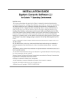
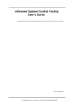
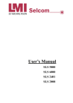
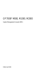
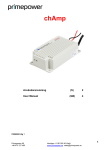
scftool(1M) overview
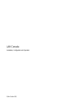
scftool(1M) provides a user interface using Motif. scftool(1M) can be used in an OpenWindows or CDE
environment.
7
[Figure1. 1 scftool screen (for GP7000F model 200/200R/400/400A/400R/600/600R, PRIMEPOWE
R 200/400/600)]
[Figure1. 2 scftool screen (for GP7000F model 1000/2000, PRIMEPOWER 800/1000/2000)]
scfconf(1M) overview
scfconf(1M) is the software setting command with the CUI interface.
For information on how to use scfconf(1M), refer to "3.5 scfconf(1M)."
1.3.2.1 POWER Switch Settings
This software can be used to automatically shut down the system when the POWER switch is pressed.
The default setting is to start the system shutdown process after the POWER switch has been pressed twice.
Under the double-press mode, pressing the POWER switch twice will start the shutdown process. This prevents
the system from being shutdown by accidentally pressing the POWER switch once. The first time the POWER
switch is pressed; you will see a confirmation message on the console. Pressing the POWER switch again within
the seconds described to "1.2.2Shutdown" will start the shutdown process.
Under the single-press mode, pressing the POWER switch will immediately start the shutdown process without
displaying the confirmation message.
Under the ignore mode, the system will not shutdown even when the POWER switch is pressed.
When the following models are used, default value is two times, and setting is not necessary.
· PRIMEPOWER 250/450/650/850/900/1500/2500/HPC2500
Notes
When the POWER switch is continuously pressed more than the set value, compulsion power supply OFF of the
system might be executed.
Please do not press the POWER switch more than the set value continuously.
1.3.2.2 System Time
For the following models, this section need not be referred to.
8
· GP7000F model 1000/2000
· PRIMEPOWER 1/100/250/450/800/900/1000/1500/2000/2500/HPC2500
This system has two hardware clocks: a system standard clockand the SCF high-resolution clockthat has a lower
degree of error. This software makes it possible to use the SCF high-resolution clock to adjust the time of the
system standard clock.
The default setting uses only the system standard clock, and does not adjust its time.
Selecting the SCF high-resolution clock will cause time to be periodically adjusted, allowing more accurate time
operation. However, changing system time by date or a similar command only affects the system standard clock.
You must use the scfdate(1M)command to synchronize the system standard clock and the SCF high-resolution
clock. Do this by executing the following:
# scfdate sync
Since system time can be changed by date(1)as well as stime(2), adjtime(2), and settimeofday(3C), you must
exercise caution when using the SCF high-resolution clock. In particularly, do not use the SCF high-resolution
clock when running NTP(Network Time Protocol) software that utilizes the network to synchronize time.
You can use the scfdate(1M)command to display the current time of the SCF high-resolution clock.
When the following models are used, the setting is unnecessary. However, when the system time is changed, it is
necessary to synchronize SCF high-resolution clock by the scfdate(1M) command.
· PRIMEPOWER 650/850
1.3.2.3 UPS Operation Time
For the following models, this section need not be referred to because UPS cannot connect by the UPS interface.
· PRIMEPOWER 1
Connecting a UPS(Uninterruptible Power Supply) to the system allows you to shut down the system gracefully
following a power down. In addition, if the power down is only for a few seconds, you may not want a system
shutdown. The system allows you to set the operation time following a power down. This time is known as the
UPS operation time.
UPS operation time is the length of delay prior to this software automatically starting the shutdown process. It
can be set from 0 second to 9999 seconds. The default delay is 5 seconds. If power returns within the UPS
operation time, the system will continue to operate.
UPS operation time is influenced by the UPS's capacity and specifications, time required to shutdown the system,
UPS charge level, and other factors. Make sure you perform through tests before deciding on the appropriate
UPS operation time.
When the following models are used, SCF driver does not have the setting. Set it by the Machine Administration.
Refer to the "Machine Administration Guide" for the setting method.
· GP7000F model 1000/2000
· PRIMEPOWER 250/450/650/800/850/900/1000/1500//2000/2500/HPC2500
1.3.2.4 Notes
When GP7000 F model 1000/2000 or PRIMEPOWER 800/1000/2000 is used, and the SCF driver package is
installed reinstalling or updating, it is necessary to set up the SCF driver again.
1.4 Troubleshooting
To protect the system from being damaged, this software automatically shuts down and turns off power when the
fan fails, or an abnormal temperature is detected. To protect hardware from damage, it also immediately turns
off power when power supply failures are detected. In this case however the system is not shut down.
With certain models redundant configurations enable continued operation even when one of the redundant
components fails, but note that the system will shut down to protect itself if all of the redundant components fail.
When a component fails, a message is displayed on the console. You can also check for failures using
fjprtdiag(1M)and hsadm(1M).
9
1.5 Processing when UPS is connected, and power failure o
ccurred
When UPS is connected to the system and the power failure occurred, SCF driver executes the shutdown
process.
At this time, SCF driver makes the work file to distinguish the shutdown due to the power failure, and starts
shutdown.
SCF driver does not make the work file when the shutdown(1M) command is executed or the POWER Switch
presses or the shutdown processing due to abnormality.
The directory and the work file name from which the work file is made are as follows.
/var/opt/FJSVhwr/UPS2.cau
The application can add special processing by the power failure by the presence of this work file.
For example, the application prepares shutdown script (/etc/rc0.d). In the shutdown script, executing special
processing when the presence of the work file is judged, and the work file exists becomes possible.
Notes
Please end the added processing within keep time (backup time) of the UPS battery.
Please consider the keep time of the UPS battery. And, do not become complicated processing.
1.6 kernel parameter of SCF driver
1.6.1 For SynfinityCluster
When using SynfinityCluster, you need to set the SCF/RCI monitoring timeout in the kernel parameter
(/etc/system) according to RCI connecting unit model or the number of partitions.
Notes
· The monitoring timeout might need to be set for some RCI connecting unit without partitions.
· You can calculate the timeout using the largest number of partitions in an RCI connecting unit.
· When the timeout setting is done, reboot a node and manually set the SynfinityCluster parameter
(failure detection monitoring time). See "5.3 Alert monitoring interval" of the "SynfinityCluster
Installation/Administration Guide".
- Model with partitions: See "Condition a. "Model 800, 1000, and 2000".
- Model without partitions: See "Condition b. Cluster system with 4 or more nodes except the above
"a".
For GP7000F model 200/200R/400/400A/400R/600/600, and PRIMEPOWER200/400/600
The monitoring timeout setting is not required.
For PRIMEPOWER 250/450
Set 2 seconds for the monitoring timeout.
· Setting up the /etc/system file
Change the /etc/system file on all cluster nodes, as follows:
1. Copy (or backup) /etc/system using /etc/system.org:
Example: # cp /etc/system /etc/system.org
2. Add the following to /etc/system. As the timeout is set up in *s units, set a value equal to the value
calculated above, multiplied by 1000000:
set FJSVscf:scf_rdctrl_sense_wait = (monitoring timeout: *s unit)
For example: /etc/system is specified as follows:
set FJSVscf:scf_rdctrl_sense_wait = 2000000
3. Reboot the system
10
For GP7000F model 1000/2000, and PRIMEPOWER 800/1000/2000
Set up the monitoring timeout in the /etc/system file as follows:
· Calculating monitoring timeout
- 2 partitions : 2 seconds
- 3 or more partitions: 1 second + (0.5 x number of partitions)
· Example 1) 3 partitions: 2.5 seconds
· Example 2) 4 partitions: 3.0 seconds
· Setting up the /etc/system file
Change the /etc/system file on all cluster nodes, as follows:
1. Copy (or backup) /etc/system using /etc/system.org:
Example: # cp /etc/system /etc/system.org
2. Add the following to /etc/system. As the timeout is set up in *s units, set a value equal to the value
calculated above, multiplied by 1000000:
set FJSVscf2:scf_rdctrl_sense_wait = (monitoring timeout: *s unit)
For example, /etc/system is specified for 2-partition configuration as follows:
set FJSVscf2:scf_rdctrl_sense_wait = 2000000
3. Reboot the system
For PRIMEPOWER 650/850
Set 2 seconds for the monitoring timeout.
· Setting up the /etc/system file
Change the /etc/system file on all cluster nodes, as follows:
1. Copy (or backup) /etc/system using /etc/system.org:
Example: # cp /etc/system /etc/system.org
2. Add the following to /etc/system. As the timeout is set up in *s units, set a value equal to the value
calculated above, multiplied by 1000000:
set FJSVscf3:scf_rdctrl_sense_wait = (monitoring timeout: *s unit)
For example: /etc/system is specified as follows:
set FJSVscf3:scf_rdctrl_sense_wait = 2000000
3. Reboot the system
For PRIMEPOWER 900/1500/2500/HPC2500
Set up the monitoring timeout in the /etc/system file as follows:
· Calculating monitoring timeout
- 2 partitions : 2 seconds
- 3 or more partitions: 1 second + (0.5 x number of partitions)
· Example 1) 3 partitions: 2.5 seconds
· Example 2) 4 partitions: 3.0 seconds
· Setting up the /etc/system file
Change the /etc/system file on all cluster nodes, as follows:
1. Copy (or backup) /etc/system using /etc/system.org:
Example: # cp /etc/system /etc/system.org
2. Add the following to /etc/system. As the timeout is set up in *s units, set a value equal to the value
calculated above, multiplied by 1000000:
set FJSVscf3:scf_rdctrl_sense_wait = (monitoring timeout: *s unit)
For example, /etc/system is specified for 2-partition configuration as follows:
set FJSVscf3:scf_rdctrl_sense_wait = 2000000
3. Reboot the system
1.6.2 For PRIMECLUSTER
When using PRIMECLUSTER, you need to set the SCF/RCI monitoring timeout according to partition
11
configuration of RCI connecting units.
Notes
· You can calculate the timeout using the largest number of partitions in an RCI connecting unit.
· Enable the timeout by rebooting the node.
For GP7000F model 200/200R/400/400A/400R/600/600, and PRIMEPOWER200/400/600
The monitoring timeout setting is not required.
For PRIMEPOWER 250/450
The monitoring timeout setting is not required.
For GP7000F model 1000/2000, and PRIMEPOWER 800/1000/2000
Set up the monitoring timeout in the /etc/system file as follows:
· Calculating monitoring timeout
- 1 or 2 nodes: 2 seconds
- 3 or more partitions: 1 second + (0.5 x number of partitions)
· Example 1) 3 partitions: 2.5 seconds
· Example 2) 4 partitions: 3.0 seconds
· Setting up the /etc/system file
Change the /etc/system file on all cluster nodes, as follows:
1. Copy (or backup) /etc/system using /etc/system.org:
Example: # cp /etc/system /etc/system.org
2. Add the following to /etc/system. As the timeout is set up in *s units, set a value equal to the value
calculated above, multiplied by 1000000:
set FJSVscf2:scf_rdctrl_sense_wait = (monitoring timeout: *s unit)
For example, /etc/system is specified for 2-partition configuration as follows:
set FJSVscf2:scf_rdctrl_sense_wait = 2000000
3. Reboot the system
For PRIMEPOWER 650/850
The monitoring timeout setting is not required.
For PRIMEPOWER 900/1500/2500/HPC2500
Set up the monitoring timeout in the /etc/system file as follows:
· Calculating monitoring timeout
- 1 or 2 partitions : 2 seconds
- 3 or more partitions: 1 second + (0.5 x number of partitions)
· Example 1) 3 partitions: 2.5 seconds
· Example 2) 4 partitions: 3.0 seconds
· Setting up the /etc/system file
Change the /etc/system file on all the nodes, as follows:
1. Copy (or backup) /etc/system using /etc/system.org:
Example: # cp /etc/system /etc/system.org
2. Add the following to /etc/system. As the timeout is set up in *s units, set a value equal to the value
calculated above, multiplied by 1000000:
set FJSVscf3:scf_rdctrl_sense_wait = (monitoring timeout: *s unit)
For example, /etc/system is specified for 2-partition configuration as follows:
set FJSVscf3:scf_rdctrl_sense_wait = 2000000
3. Reboot the system
12
Chapter 2 Expansion Disk Cabinet/Expansion F
ile Unit
This chapter describes the RAS (Reliability, Availability, and Serviceability) features of the SCSI Expansion Disk
Cabinet(at the following: Expansion Disk Cabinet) and SCSI Expansion File Unit(at the following: Expansion
File Unit).
2.1 Feature Overview
SCF driver offers the following RAS (Reliability, Availability, and Serviceability) features of the Expansion Disk
Cabinet/Expansion File Unit which connects RCI.
The following features are available.
When the SCSI Expansion File Unit without RCI, SCF driver offers only the hot-swapping of internal disks.
· Notifies the system when power supply failures, abnormal temperatures or fan breakdowns occur on
Expansion Disk Cabinets/Expansion File Units.
This function is not offered to the following models.
- PRIMEPOWER 1
· Allows the hot-swapping of redundant power supplies and fans on Expansion Disk Cabinets/ Expansion
File Units.
This function is not offered to the following models.
- PRIMEPOWER 1
· This function is available in the rcinodeadm(1M) command the following models offer.
- GP7000F model 200/200R/400/400A/400R/600/600R
- PRIMEPOWER 200/400/600
· Models not listed above can be operated by the "Machine Administration" or "System console".
Refer to "Machine Administration Guide" or "System Console Software User's Guide".
· Allows the hot-swapping of internal disks on Expansion Disk Cabinets/ Expansion File Units.
2.2 Setup of Expansion Disk Cabinet/ Expansion File Unit
An SCSI Expansion Disk Cabinet/SCSI Expansion File Unit which connects RCI should be included in the
system before being used.
However, SCF does not provide commands to do this.
Moreover, the following models are off the subject of this function.
· PRIMEPOWER 1
As for including in the system, the operation is different because of each model.
For the following models, the RCI command that OBP(OpenBoot PROM) offers is used.
· GP7000F mdel 200/200R/400/400A/400R/600/600R
· PRIMEPOWER 200/250/400/450/600/650/850
Refer to "PRIMEPOWER USER'S MANUAL" or "GP7000F USER'S MANUAL" for information on how to include
the Expansion Disk Cabinet/Expansion File Unit using OBP RCI commands.
The following models are operated by "System Console".
· GP7000F model 1000/2000
· PRIMEPOWER 800/900/1000/1500/2000/2500/HPC2500
Refer to "PRIMEPOWER USER'S MANUAL" or "GP7000F USER'S MANUAL", and refer to " System Console
Software User's Guide ".
When the Expansion File Unit without RCI is used, it need not be operated to include it in the system.
Refer to " USER'S MANUAL" of the Expansion File Unit.
2.3 Troubleshooting
SCF driver allows system notification of problems occurring in the SCSI Expansion Disk Cabinet/SCSI
Expansion File Unit, such as power supply failures, abnormal temperatures or fan failures. Messages are
displayed on the console in each case.
The system server will continue operation despite problems occurring in the Expansion Disk Cabinet/Expansion
File Unit, as SCF driver does not, in any case, shut down the system server.
13
When it is impossible for the Expansion Disk Cabinet/Expansion File Unit to continue operation due to
abnormal temperatures or other potential problems, the hardware shuts off power to the Expansion Disk
Cabinet/Expansion File Unit after detecting the failures.
The Expansion Disk Cabinet/Expansion File Unit should be isolated, or other appropriate steps should be taken,
according to the messages and circumstances.
14
Chapter 3 Command Reference
This chapter describes the commands offered by SCF driver.
Refer to the following "" for the command offered by each model.
[Table 3. 1 The offer list of commands]
Models
Commands
PRIMEPOWER
1
GP7000F
Model
200/200R/400/
400A/400R/
600/600R
PRIMEPOWER
200/400/600
PRIMEPOWER
250/450
GP7000F
Model
1000/2000
PRIMEPOWER
800/1000/2000
PRIMEPOWER
650/850/
900/1500/
2500/HPC2500
fjprtdiag(1M)
O
O
O
O
O
hsadm(1M)
O
O
X
X
X
diskadm(1M)
O
O
O
O
O
scftool(1M)
X
O
X
O
X
scfconf(1M)
O
O
X
X
X
scfdate(1M)
X
O
X
X
O *1
scfwdtimer(1M)
O
X
X
X
X
rcihello(1M)
X
O
X
X
X
rciinfo(1M)
X
O
O
O
O
rcinodeadm(1M)
X
O
X
X
X
rciopecall(1M)
X
O
O
O
O
nodeled
X
X
O
X
X
iompadm(1M)
X
X
O
O
O
prtdiag(1M)
*2
*2
*2
*2
*2
O : offer X : Unoffer
*1 : There is a condition in the command operation on each model.
*2 : SCF driver is not offering this command from ESF2.2.
3.1 fjprtdiag(1M)
NAME
fjprtdiag - Prints system diagnostic information
SYNOPSYS
/opt/FJSVhwr/sbin/fjprtdiag [ -v ] [ -l ]
AVAILABILITY
FJSVscu, FJSVlscu, FJSVpscu, FJSVscu1, FJSVscu2, FJSVscu3
DESCRIPTION
fjprtdiag displays system configuration information and system diagnostic information.
System diagnostic information includes information on degraded devices caused by failures.
The interface, output format, and installation location may change in future releases.
15
OPTIONS
By default, fjprtdiag displays the following information:
·
·
·
·
·
·
·
·
·
·
System Configuration
System clock frequency
Memory size
Extended interleave mode (for PRIMEPOWER 650/850/900/1500/2500/HPC2500)
CPU Units
Used Memory
Unused Memory (Displays when there is partial failure in memory used.)
IO Cards
Failed Units in System Initialization
Detected Recent System faults
The following options are available:
-v
Verbose mode
Additionally displays detailed information that is environment information and OBP version information.
"System Temperature" is not displayed in the following models.
- PRIMEPOWER 1
- GP7000F model 1000/2000, and PRIMEPOWER 800/1000/2000
- PRIMEPOWER 900/1500/2500/HPC2500
-l
Log output
Outputs information to syslogd(1M)only when failures and errors occur on the system. If it is specified
along with -v, detailed information is always output to syslogd(1M).
EXAMPLES
For PRIMEPOWER 1
% /opt/FJSVhwr/sbin/fjprtdiag
System Configuration: Fujitsu/PFU sun4u Fujitsu PRIMEPOWER 1 1x UltraSPARC-IIe 400MHz
System clock frequency: 67 MHz
Memory size: 64Mb
CPU Units: Number Frequency Cache-Size Version
No.
MHz
MB Impl. Mask
No.
----- ----- ----- ----- ----CPU#0
400
0.2
13
MHz
MB Impl. Mask
----- ----- ----- ----- -----
1.2
Used Memory: Slot-Number Size
No.
MB
------- ----SLOT0
No.
MB
No.
------- -----
MB
------- -----
No.
MB
------- -----
64
====================================IO Cards===================================
Slot
Name
Model
Bus(max freq.)
--------- ------------------------- --------------------------- ---------------No failures found in System Initialization
==========================================
No Recent System Faults found
=============================
For GP7000F model 200/200R/400/400A/400R/600/600R and PRIMEPOWER 200/400/600
% /opt/FJSVhwr/sbin/fjprtdiag
16
System Configuration: Fujitsu/PFU sun4us Fujitsu PRIMEPOWER 200 1x SPARC64-III 272MHz
System clock frequency: 73 MHz
Memory size: 64Mb
CPU Units: Number Frequency Cache-Size Version
No.
MHz
MB Impl. Mask
No.
----- ----- ----- ----- ----CPU#0
272
4.0
3
MHz
MB Impl. Mask
----- ----- ----- ----- -----
2.0
Used Memory: Slot-Number Size
No.
MB
No.
------- ----SLOT0
32
MB
No.
------- ----SLOT1
MB
No.
------- -----
MB
------- -----
32
====================================IO Cards====================================
Slot
Name
Model
Bus(max freq.)
---------- ------------------------ --------------------------- ---------------PCI#6
scsi-glm
Symbios,53C875
PCIBUS#D(33Mhz)
No failures found in System Initialization
==========================================
No Recent System Faults found
=============================
For PRIMEPOWER 250/450
% /opt/FJSVhwr/sbin/fjprtdiag -v
System Configuration: Fujitsu sun4us Fujitsu PRIMEPOWER250 2x SPARC64 IV
System clock frequency: 220 MHz
Memory size: 64Mb
Memory size: 1024Mb
CPU Units: Number Frequency Cache-Size Version
No.
MHz
MB Impl. Mask
No.
-------- ----- ----- ----- ----CPU#0
675
4.0
4
0.7
MHz
MB Impl. Mask
-------- ----- ----- ----- ----CPU#1
675
4.0
4
0.7
Used Memory: Slot-Number Size
No.
MB
--------- ----SLOT#0
256
No.
MB
No.
--------- ----SLOT#1
256
MB
--------- ----SLOT#2
256
No.
MB
--------- ----SLOT#3
256
====================================IO Cards====================================
Slot
Name
Model
max freq.
--------- ------------------------- --------------------------- ---------------PCI#00
scsi-glm
PCI#01
SUNW,hme-pci108e,1001
Symbios,53C875
SUNW,qsi-cheerio
33Mhz
33Mhz
No failures found in System Initialization
==========================================
17
No Recent System Faults found
=============================
==================Environmental Status=================================
MODE switch position is in MAINTE. mode
System Temperature (C):
AMBIENT
25
System PROM revisions:
---------------------RST 1.1.4 2002/10/18 15:12
POST 1.1.3 2002/10/15 14:03
For GP7000F model 1000/2000 and PRIMEPOWER 800/1000/2000
% /opt/FJSVhwr/sbin/fjprtdiag -v
System Configuration: Fujitsu/PFU sun4us Fujitsu Siemens GP7000F 2000 2-slot 5x
SPARC64-III 300MHz
System clock frequency: 100 MHz
Memory size: 4096Mb
CPU Units: Number Frequency Cache-Size Version
No.
MHz
MB Impl. Mask
No.
-------- ----- ----- ----- ----00-CPU#0
300
8.0
3
4.0
00-CPU#2
300
8.0
3
4.0
07-CPU#0
300
8.0
3
4.0
MHz
MB Impl. Mask
-------- ----- ----- ----- ----00-CPU#1
300
8.0
3
4.0
07-CPU#1
300
8.0
3
4.0
Used Memory: Slot-Number Size
No.
MB
----------- -----
No.
MB
No.
----------- -----
MB
No.
----------- -----
MB
----------- -----
00-SLOT#A00
128
00-SLOT#A01
128
00-SLOT#A02
128
00-SLOT#A03
128
00-SLOT#A10
128
00-SLOT#A11
128
00-SLOT#A12
128
00-SLOT#A13
128
00-SLOT#A20
128
00-SLOT#A21
128
00-SLOT#A22
128
00-SLOT#A23
128
00-SLOT#A30
128
00-SLOT#A31
128
00-SLOT#A32
128
00-SLOT#A33
128
07-SLOT#A00
128
07-SLOT#A01
128
07-SLOT#A02
128
07-SLOT#A03
128
07-SLOT#A10
128
07-SLOT#A11
128
07-SLOT#A12
128
07-SLOT#A13
128
07-SLOT#A20
128
07-SLOT#A21
128
07-SLOT#A22
128
07-SLOT#A23
128
07-SLOT#A30
128
07-SLOT#A31
128
07-SLOT#A32
128
07-SLOT#A33
128
====================================IO Cards====================================
Slot
Name
Model
max freq.
--------- ------------------------- --------------------------- ---------------00-PCI#0B scsi-glm
00-PCI#0A SUNW,hme-pci108e,1001
07-PCI#0B scsi-glm
18
Symbios,53C875
SUNW,qsi-cheerio
Symbios,53C875
33Mhz
33Mhz
33Mhz
07-PCI#1B pci-pci1011,24
33Mhz
No failures found in System Initialization
==========================================
No Recent System Faults found
=============================
==================Environmental Status=================================
MODE switch position is in LOCK mode
System PROM revisions:
---------------------RST 3.11.1 1999/10/16 13:26
POST 1.1.8 1999/12/01 14:25
For PRIMEPOWER 650/850/900/1500/2500/HPC2500
% /opt/FJSVhwr/sbin/fjprtdiag -v
System Configuration: Fujitsu sun4us Fujitsu PRIMEPOWER850 2-slot 8x SPARC64
IV 675MHz
System clock frequency: 112 MHz
Memory size: 4096Mb
Extended Interleave Mode: Disable
CPU Units: Number Frequency Cache-Size Version
No.
MHz
MB Impl. Mask
No.
----------- ----- ----- ----- -----
MHz
MB Impl. Mask
----------- ----- ----- ----- -----
C0S00-CPU#0
675
8.0
4
0.7
C0S00-CPU#1
675
8.0
4
0.7
C0S00-CPU#2
675
8.0
4
0.7
C0S00-CPU#3
675
8.0
4
0.7
C0S01-CPU#0
675
8.0
4
0.7
C0S01-CPU#1
675
8.0
4
0.7
C0S01-CPU#2
675
8.0
4
0.7
C0S01-CPU#3
675
8.0
4
0.7
Used Memory: Slot-Number Size
No.
MB
-------------- -----
No.
MB
-------------- -----
C0S00-SLOT#A00
256
C0S00-SLOT#B00
256
C0S00-SLOT#A01
256
C0S00-SLOT#B01
256
C0S00-SLOT#A02
256
C0S00-SLOT#B02
256
C0S00-SLOT#A03
256
C0S00-SLOT#B03
256
C0S01-SLOT#A00
256
C0S01-SLOT#B00
256
C0S01-SLOT#A01
256
C0S01-SLOT#B01
256
C0S01-SLOT#A02
256
C0S01-SLOT#B02
256
C0S01-SLOT#A03
256
C0S01-SLOT#B03
256
====================================IO Cards====================================
Sub
Freq
19
Brd Brd Slot
Name
Model
MHz
--- --- ------------ ------------------------- ---------------------------- ---0
C0M00-PCI#00 scsi-glm
Symbios,53C875
0
C0M00-PCI#01 SUNW,hme-pci108e,1001
33
SUNW,qsi-cheerio
33
No failures found in System Initialization
==========================================
No Recent System Faults found
=============================
==================Environmental Status=================================
MODE switch position is in LOCK mode
System Temperature (C):
AMBIENT
25
System PROM revisions:
---------------------RST 1.1.18 2001/08/22 22:24
POST 1.1.11 2001/08/28 10:03
Notes
prtdiag(1M) command offered in before ESF2.1 is offered by fjprtdiag(1M) command in ESF2.2 or later.
When ESF2.2 or later is installed environment, please use this command.
prtdiag(1M) command is installed in /usr/platform/`uname -i`/sbin directory.
However, the display format and the contents are quite different from fjprtdiag(1M) command.
Please do not use /usr/platform/`uname -i`/sbin/prtdiag.
EXIT STATUS
This command returns the following values:
0
>0
No failures or errors detected on the system.
Failures or errors detected on the system, or software errors detected.
SEE ALSO
uname(1), modinfo(1M), prtconf(1M), psrinfo(1M), sysdef(1M), syslogd(1M), openprom(7D)
3.2 hsadm(1M)
NAME
hsadm - Supports hot-swapping of internal power units and fans
SYNOPSYS
/opt/FJSVhwr/sbin/hsadm action unit
AVAILABILITY
FJSVscu, FJSVlscu
20
DESCRIPTION
hsadm supports the hot-swapping of internal power units and fans.
This command displays the state of power supplies and fans and starts/stops the monitoring feature for both of
those devices.
The command line must contain one action and at least one unit.
You can specify display, enable, or disable for action.
You can specify power and/or fan for unit.
The following models can use this command.
· GP7000F model 200/200R/400/400A/400R/600/600R
· PRIMEPOWER 1/100/200/400/600
EXAMPLES
action
display unit
Displays the status of the specified unit. The following shows the display format:
Power unit:
Monitoring Mode: On / Off
FEP#0 State: Okay / Needs maintenance
Fan unit:
Monitoring Mode: On / Off
FAN#0 State: Okay / Needs maintenance
disable unit
Stops the monitoring feature for all specified units.
enable unit
Restarts the monitoring feature for all specified units.
EXIT STATUS
This command returns the following values:
0
1
Ended normally
Error
NOTES
While hot-swapping a power supply, hsadm(1M) command does not display the state of the power supply which
is removed.
After hot-swapping power supplies, use hsadm(1M) command to confirm that all of the power supplies which are
installed are in state Okay.
Note that only the super user can execute this command.
3.3 diskadm(1M)
NAME
diskadm - Supports hot-swapping of disks
SYNOPSYS
/opt/FJSVhwr/sbin/diskadm subcommandpathname ...
AVAILABILITY
FJSVscu, FJSVlscu, FJSVpscu, FJSVscu1, FJSVscu2, FJSVscu3
DESCRIPTION
diskadm supports hot-swapping of disks.
This command displays disk status.
21
The command line must contain one subcommand and at least one pathname.
For pathname, you can specify a physical name, logical name or logical controller number cN (N is the logical
number of the controller).
Example:
Physical name
/devices/pci@1f,4000/..../sd@0,0:a
Logical name
/dev/rdsk/c0t0d0s0
Controller number
c0
EXAMPLE
subcommand
display pathname
Displays the status information on specified disks. You can specify several path names for pathname in
a single command line.
The following example shows how information is displayed.
For disks to which power is being supplied, diskadm checks them and displays status information.
For disks to which power is not supplied, diskadm displays OFFLINE for status information.
ONLINE
Power is being supplied
OFFLINE
Power is not being supplied
BROKEN?
Disk controller is not responding or disk is not installed
NOTE: You must specify a path name containing a disk slice identifier that is assigned to the existing
disk slice.
1)Controller specified. (Example: Installed target: 0, 2, 3, 4)
# diskadm display c0
Controller is : /device/....
(c0)
Device Status:
Target0
Target2
Target3
Target4
ONLINE
OFFLINE
ONLINE
ONLINE
Targets corresponding to existing device path are displayed.
2)Disk specified. (Example: Installed target: 0, 3)
# diskadm display /dev/rdsk/c0t0d0s2 /dev/rdsk/c0t3d0s2
Controller is: /device/......
Device Status:
Target0
Target3
ONLINE
OFFLINE
NOTES
Only the super user can execute this command.
EXIT STATUS
This command returns the following values:
0
1
22
Ended normally
Error
3.4 scftool(1M)
NAME
scftool - GUI controlling SCF features
SYNOPSYS
/opt/FJSVhwr/sbin/scftool
AVAILABILITY
FJSVscu, FJSVscu2
DESCRIPTION
scftool is a GUI tool for controlling the following SCF features:
The following models can use this command.
· GP7000F model 200/200R/400/400A/400R/600/600R/1000/2000
· PRIMEPOWER 200/400/600/800/1000/2000
Power switch settings
Number of times in which power switch until the shutdown beginning is pushed can be set.
The setting can select "Single(1 time)", "Double(2 times)" or "ignore". The default setting is "Double".
System clock setting
Specifies whether it is preferred to use the system standard clock or to adjust the time of the system
standard clock using the SCF high-resolution clock that has a lower degree of error.
The following models can use this setting.
· GP7000F model 200/200R/400/400A/400R/600/600R and PRIMEPOWER 200/400/600.
The setting can select "System Default" or "SCF clock". The default setting is "System Default".
Since system time can be changed by date(1) as well as stime(2), adjtime(2), and settimeofday(3C), you
must exercise caution when
using the SCF high-resolution clock. In particularly, do not use the SCF high-resolution clock when
running NTP (Network Time Protocol) software that utilizes the network to synchronize time.
UPS operation settings
Specifies the time from power down to the beginning of shutdown.
If power does not come up again within the length of delay, this software will start the shutdown
process.
The following models can use this setting.
· GP7000F model 200/200R/400/400A/400R/600/600R and PRIMEPOWER 200/400/600.
The delay can be set from 0 second to 9999 seconds. The default delay is 5 seconds.
EXIT STATUS
This command returns the following values:
0
>0
Ended normally
Error
NOTES
Only the super user can execute this command.
When GP7000F model 1000/2000 and PRIMEPOWER 800/1000/2000 are used and "power switch settings" is set
to differ in each partition, the set value of each partition becomes effective.
For example: When "Single" is specified for a certain partition and "Double" is specified as for another partition,
and if power switch is pushed only once, as for the partition which specifies "Single" the shutdown is done.
23
SEE ALSO
scfdate(1M)
3.5 scfconf(1M)
NAME
scfconf - CUI controlling SCF features
SYNOPSYS
For PRIMEPOWER 1
/opt/FJSVhwr/sbin/scfconf [-p {1|2|off}]
For GP7000F model 200/200R/400/400A/400R/600/600R and PRIMEPOWER 200/400/600
/opt/FJSVhwr/sbin/scfconf [-p {1|2|off}] [-c {scf|tod}] [-u time]
AVAILABILITY
FJSVscu, FJSVlscu
DESCRIPTION
scfconf controls the following SCF features:
The following models can use this command.
· GP7000F model 200/200R/400/400A/400R/600/600R
· PRIMEPOWER 1/200/400/600
Power switch settings
Number of times in which power switch until the shutdown beginning is pushed can be set.
The setting can select "1 (one time)", "2 (two times)" or "off(ignore)".
The default setting is "2". After power switch has been pressed twice, the shutdown process is started.
System clock settings
Specifies whether it is preferred to use the system standard clock or to adjust the time of the system
standard clock using the SCF high-resolution clock that has a lower degree of error.
The following models can use this setting.
· GP7000F model 200/200R/400/400A/400R/600/600R and PRIMEPOWER 200/400/600.
The setting can select "scf" or "tod". The default setting is "tod".
Since system time can be changed by date(1) as well as stime(2), adjtime(2), and settimeofday(3C), you
must exercise caution when
using the SCF high-resolution clock. In particularly, do not use the SCF high-resolution clock when
running NTP (Network Time Protocol) software that utilizes the network to synchronize time.
UPS operation settings
Specifies the time from power down to the beginning of shutdown.
If power does not come up again within the length of delay, this software will start the shutdown
process.
The following models can use this setting.
· GP7000F model 200/200R/400/400A/400R/600/600R and PRIMEPOWER 200/400/600.
The delay can be set from 0 second to 9999 seconds. The default delay is 5 seconds.
OPTIONS
The following options are available. If no options are specified, the settings remain unchanged.
24
-p 1
The system begins shutdown when the power switch is pressed once.
-p 2
The system begins shutdown when a power switch is pressed twice. You must press the power switch
again within 5 seconds before the first press is ignored.
-p off
Pressing a power switch is always ignored.
-c scf
-c tod
-u time
Adjusts the time of the system standard clock using the SCF high-resolution clock.
This specification is specifiable with GP7000F model 200/200R/400/400A/400R/600/600R
PRIMEPOWER 200/400/600.
and
Only the system standard clock is used.
This specification is specifiable with
PRIMEPOWER 200/400/600.
200/200R/400/400A/400R/600/600R
and
time: Specifies the length of delay in seconds until this software starts the shutdown process.
This specification is specifiable with GP7000F model 200/200R/400/400A/400R/600/600R
PRIMEPOWER 200/400/600.
and
GP7000F
model
EXAMPLES
# /opt/FJSVhwr/sbin/scfconf -p off -c scf
NOTES
Only the super user can execute this command.
EXIT STATUS
This command returns the following values:
0
>0
Ended normally
Error
SEE ALSO
scfdate(1M), scftool(1M)
3.6 scfdate(1M)
NAME
scfdate - Checks the SCF high-resolution clockand synchronizes with the system standard clock
SYNOPSYS
/opt/FJSVhwr/sbin/scfdate [sync]
AVAILABILITY
FJSVscu, FJSVscu3
DESCRIPTION
scfdate checks the SCF high-resolution clock and then reads the time of the system standard clock in order to
reset the SCF high-resolution clock.
The following models can use this command.
· GP7000F model 200/200R/400/400A/400R/600/600R
· PRIMEPOWER 200/400/600/650/850
Running this command without any arguments displays the current time of the SCF high-resolution clock.
Specifying the sync option sets system time from the system standard clock to the SCF high-resolution clock.
Even if this command is offered to PRIMEPOWER 900/1500/2500/HPC2500, and specifies the sync option,
operation is invalid.
25
EXAMPLES
prompt% scfdate
Tue Oct 27 18:40:38 JST 1998
# date 1157
Tue Oct 27 11:57:00 JST 1998
# scfdate sync
Tue Oct 27 11:57:00 JST 1998
NOTES
If you use scftool(1M) or scfconf(1M) to operate the system with the setting for using the SCF high-resolution
clock and you change system time with commands such as date(1), you must synchronize the time of the SCF
high-resolution clock. Note that only the super user can execute the sync option of this command.
When the system is started in the single user mode, and system clock is changed, after /opt directory is mounted
by using maount(1M) and mountall(1M) this command can be executed.
EXIT STATUS
This command returns the following values:
0
>0
Ended normally
Error
3.7 scfwdtimer(1M)
NAME
scfwdtimer - Controls the watchdog timer function
SYNOPSYS
/opt/FJSVhwr/sbin/scfwdtimer [enable | disable]
AVAILABILITY
FJSVlscu
DESCRIPTION
scfwdtimer controls watchdog timer function of System Monitor.
The following models can use this command.
· PRIMEPOWER 1
If you specify enable, the watchdog timer function will be effective.
It allows rebooting a system automatically when a system is not responding over 14 minutes.
This is equivalent to pressing a reset switch.
At this point, all the programs running on the system are stopped forcibly, and data held only in the memory is
destroyed.
If you specify disable, the watchdog timer function will stop without monitoring the system.
This function is disabled every time you start the system.
If you use this function, specify enable each time you start the system.
EXIT STATUS
This command returns the following values:
0
>0
Ended normally
Error
NOTES
· If you specify enable, this function activates when a system saves a memory dump. Saving of memory
dump fails when saving of memory dump takes more than 14 minutes.
· This function is effective only on models where System Monitor has the watchdog timer function.
26
See the documentation provided with each product for information about the watchdog timer function.
3.8 rcihello(1M)
NAME
rcihello - Controls CHECK LEDs of units connected via RCI
SYNOPSYS
/opt/FJSVhwr/sbin/rcihello { on | off } [ address ]
AVAILABILITY
FJSVscu
DESCRIPTION
rcihello controls CHECK LEDs of units connected via RCI
The following models can use this command.
· GP7000F model 200/200R/400/400A/400R/600/600R
· PRIMEPOWER 200/400/600/650/850
OPTIONS
The following options are available:
Address
Specifies units to be controlled, which are connected via RCI. If no address is specified, all of the units
connected via RCI will be controlled. Addresses are given in 8-digit hexadecimal.
on
Blinks CHECK LEDs
off
Stops blinking CHECK LEDs
EXAMPLES
# rcihello on 003001ff
NOTES
The off option does not necessarily turn off CHECK LEDs. The CHECK LEDs with the addresses, which you did
not specify to blink on the rcihello command line, reflect the internal status of the units connected via RCI.
Where old information remains on RCI devices that were previously connected, but currently are not, rcihello
executed with no address (control for all of the units connected via RCI) will display error messages.
In this case, you must reconfigure RCI setting.
Note that only the super user can execute this command.
For the model by whom this command is not offered, "Machine Administration" offers the function equal with
this command. Please refer to Machine Administration Guide".
EXIT STATUS
This command returns the following values:
0
>0
Ended normally
Error
SEE ALSO
rciinfo(1M), rcinodeadm(1M)
3.9 rciinfo(1M)
NAME
rciinfo - Displays information on units connected via RCI
27
SYNOPSYS
/opt/FJSVhwr/sbin/rciinfo
AVAILABILITY
FJSVscu, FJSVpscu, FJSVscu2, FJSVscu3
DESCRIPTION
rciinfo displays information on units connected via RCI. Values displayed, such as address, status and so on, are
all given in hexadecimal.
The following models can use this command.
· GP7000F model 200/200R/400/400A/400R/600/600R/1000/2000
· PRIMEPOWER 200/250/400/450/600/650/800/850/900/1000/1500/2000/2500/HPC2500
EXAMPLES
# rciinfo
HOST
address:000101ff mode:010038a0 status:80000000
LIST
address status device-class sub-class category
000101ff
9a
0001
04
host
003001ff
90
0400
04
disk
003002ff
90
0400
05
disk
HOST displays information on the system server.
LIST displays information on units connected via RCI together with those on the system server.
NOTES
This command displays device information in the RCI configuration table.
It does not display information on devices that are physically connected but not configured. It does displays
information on devices that are not connected but remain in the RCI configuration.
In those cases, you must reconfigure using OBP commands.
EXIT STATUS
This command returns the following values:
0
>0
Ended normally
Error
SEE ALSO
rcinodeadm(1M), rcihello(1M)
3.10 rcinodeadm(1M)
NAME
rcinodeadm - Controls monitoring units connected via RCI
SYNOPSYS
/opt/FJSVhwr/sbin/rcinodeadm address action
AVAILABILITY
FJSVscu
28
DESCRIPTION
rcinodeadm supports the hot swapping of internal power supply and fan in the External Disk Cabinet connected
to the system server via RCI. This command starts/stops the monitoring feature for both devices.
This command also operates fan test and turns off CHECK LEDs when monitoring is restarted.
The following models can use this command.
· GP7000F model 200/200R/400/400A/400R/600/600R
· PRIMEPOWER 200/250/400/450/600
OPTIONS
address
Specifies addresses of units connected via RCI. You should specify addresses in a format that rciinfo can
display (that is 8-digit hexadecimal).
You can specify the following value for action.
disable
enable
Stops monitoring units connected via RCI
Restarts monitoring units connected via RCI
EXAMPLES
# rcinodeadm 003006ff disable
RCI 003006ff: alarm off
NOTES
If the CHECK LED on RCI device is turned on due to self-detection of internal failures, it stays lit after
monitoring has restarted.
Note that only the super user can execute this command.
EXIT STATUS
This command returns the following values:
0
>0
Ended normally
Error
SEE ALSO
rciinfo(1M), rcihello(1M)
3.11 rciopecall(1M)
NAME
rciopecall - Reports operator call on units connected via RCI
SYNOPSYS
/opt/FJSVhwr/sbin/rciopecall address {disp | on callNo | off callNo}
AVAILABILITY
FJSVscu, FJSVpscu, FJSVscu1, FJSVscu2, FJSVscu3
DESCRIPTION
rciopecall reports operator call on units connected via RCI.
The following models can use this command.
· GP7000F model 200/200R/400/400A/400R/600/600R/1000/2000
· PRIMEPOWER 200/250/400/450/600/650/800/850/900/1000/1500/2000/2500/HPC2500
29
OPTIONS
The following options are available:
address
Specifies addresses of units connected via RCI. Addresses are given in 8-digit hexadecimal.
You can specify the following value for action.
disp
Displays the operator call
on
Sets the operator call ON
off
callNo
Sets the operator call OFF
If "on" or "off" is specified for action, specifies callNo that controls the operator call. callNo is given in
2-digit hexadecimal.
callNo is set up only in the device that "1" is specified in bit by the ON/OFF designation. It is possible
that more than one bit is specified at the same time.
EXAMPLES
# rciopecall 000101ff on 0c
# rciopecall 000101ff off 0c
# rciopecall 000101ff disp
address:000101ff callNo:0c status:00
NOTES
Note that only the super user can execute this command.
This status code returns the following values:
00
Meaning
Ended normally
Meaning
Not support on
the specified node
Action
Check the RCI
address.
Meaning
Command
Timeout
Action
Check the RCI
address, and retry
to the command.
20
40
EXIT STATUS
This command returns the following values:
0
>0
Ended normally
Error
3.12 nodeled(1M)
NAME
nodeled - LED lamp control/status display command of this system
SYNOPSYS
LED lamp control
/opt/FJSVhwr/sbin/nodeled [-led check] -mode on | blink | off
30
LED lamp status display
/opt/FJSVhwr/sbin/nodeled [-led check] -status
AVAILABILITY
FJSVpscu
DESCRIPTION
This is a command to display the control and the state of the LED lamp of Main Cabinet.
In this command, the CHECK lamp of the Main Cabinet can be controlled.
To specify the target processor from remoteness at maintenance, the CHECK lamp is lit or can be blinked by this
command.
Moreover, status display of the CHECK lamp can be done.
The following models can use this command.
· PRIMEPOWER 250/450
OPTIONS
The following options are available:
-led check
Specify the LED lamp. This parameter can be omitted.
check : CHECK lamp
-mode
Specify ON(lighting), BLINK(blinking), and OFF(release) of the LED lamp. This parameter cannot be
specified with "-status" parameter.
ON
: LED lamp is lit
BLINK : LED lamp is blinked
OFF : Lighting or blinking the LED lamp is released. This parameter is returned to
the previous state to which the LED lamp is lit or blinked by this command.
-status
The state of the LED lamp is displayed. This parameter cannot be specified with "-mode" parameter.
ON
: State of lighting
BLINK : State of blinking
OFF
: State of turning off
EXAMPLES
# /opt/FJSVhwr/sbin/nodeled -led check -mode blink
# /opt/FJSVhwr/sbin/nodeled -led check -status
=== LED ====================
CHECK(Amber) ------ ON
EXIT STATUS
This command returns the following values:
0
>0
Ended normally
Error
3.13 iompadm(1M)
NAME
iompadm - Multipath control command
SYNOPSYS
/usr/opt/FJSViomp/bin/iompadm [-p] -c class-name subcommand [parameter]
31
AVAILABILITY
FJSVpscu, FJSVscu2, FJSVscu3, FJSViomp
DESCRIPTION
iompadm displays the status of the communication paths composed of the interfaces.
This command also restores the communication path where a failure occurs.
You can display the status of communication paths or restore them using the combination of the specified
subcommand and parameter.
A communication path is a path that the SCF driver uses for communications with a SCF driver: one
communication path for each system board.
The following models can use this command.
· GP7000F model 1000/2000
· PRIMEPOWER 250/450/650/800/850/900/1000/1500/2000/2500/HPC2500
OPTIONS
The following options are available:
-c calss-name :
Specifies a class name.
For PRIMEPOWER 250/450
"FJSVscf" must be specified.
For GP7000F model 1000/2000 and PRIMEPOWER 800/1000/2000
"FJSVscf2" must be specified.
For PRIMEPOWER 650/850/900/1500/2500/HPC2500
"FJSVscf3" must be specified.
-p :
Displays a communication path's logical and physical device name. If this option is omitted, only the
logical device name will be displayed.
Subcommand :
"Table 3. 1 Subcommand List" lists the subcommands you can specify and gives their descriptions.
[Table 3. 1 Subcommand List]
Subcommand
Description
info
Displays the configuration information
of the specified interface or all
interfaces, and the status of
communication paths.
status
Displays the status of the specified
communication path.
ident
Displays the class to which the specified
communication path belongs.
probe
Displays the interface to which specified
communication path belongs.
recover
Restores the specified communication
path.
start
After the recover subcommand is
running, this subcommand makes the
specified communication path available
for communicating.
version
Displays the version information for this
product.
help
Displays the usage of the iompadm
command.
32
Parameter :
Specifies a parameter in combination with the subcommands. For more information, see "3.13.1iompadm
subcommand."
EXIT STATUS
This command returns the following values:
0
>0
Ended normally
Error
3.13.1 iompadm subcommand
3.13.1.1 info subcommand
DESCRIPTION
info subcommand displays the configuration information of the specified interface or all interfaces, and the
status of communication paths.
If no interface name is specified, information for all of the interfaces that comprise the IOMP on the system will
be displayed. In this case, the IOMP drivers except for the SCF driver will be included in the information.
If you want to view information about the SCF driver, specify "/dev/FJSVhwr/fiomp/mscf0" for an interface name.
SYNOPSYS
/usr/opt/FJSViomp/bin/iompadm [-p] -c FJSVscf3 info [Interface name]
EXAMPLE
Example : For PRIMEPOWER 850
When -p option is not specified:
# /usr/opt/FJSViomp/bin/iompadm -c FJSVscf3 info /dev/FJSVhwr/fiomp/mscf0
IOMP: /dev/FJSVhwr/fiomp/mscf0
Element:
/dev/FJSVhwr/scfc0
online active block
"Good"
/dev/FJSVhwr/scfc1
online standby block
"Good"
Node:
/dev/FJSVhwr/pwrctl
/dev/FJSVhwr/pwrctl2
/dev/FJSVhwr/rcictl
/dev/FJSVhwr/rcictl2
/dev/FJSVhwr/rasctl
/dev/FJSVhwr/rasctl2
Function:
MPmode=false
AutoPath=true
Block=true
NeedSync=false
Specify the -p option:
# /usr/opt/FJSViomp/bin/iompadm -p -c FJSVscf3 info /dev/FJSVhwr/fiomp/mscf0
IOMP: /dev/FJSVhwr/fiomp/mscf0
-> /device/pseudo/FJSVscf3@1024:mscf0
Element:
/dev/FJSVhwr/scfc0
online active block
"Good"
33
-> /devices/pci@83,4000/ebus@1/FJSV,scfc@14, 200000:scfc0
/dev/FJSVhwr/scfc1
online standby block
"Good"
-> /devices/pci@8f,4000/ebus@1/FJSV,scfc@14, 200000:scfc1
Node:
/dev/FJSVhwr/pwrctl
/dev/FJSVhwr/pwrctl2
/dev/FJSVhwr/rcictl
/dev/FJSVhwr/rcictl2
/dev/FJSVhwr/rasctl
/dev/FJSVhwr/rasctl2
Function:
MPmode=false
AutoPath=true
Block=true
NeedSync=false
"Table 3. 2 Communication path status" explains information output in the above examples.
[Table 3. 2 Communication path status]
Information
online/offline
Description
Indicates the status of the
communication path:
online : enabled to communicate
offline : disabled to communicate
Indicates the detailed status of the
communication path:
active/standby/stop/fail/disconnected
block/unblock
active : enabled to communicate or
being communicated
standby: ready for communication
but in an idle state
stop : stopped state
fail : disabled to communicate
caused by a failure
disconnected:
detached communication path by
Dynamic Reconfiguration
Indicates whether incoming direct
access to the communication path
is permitted:
block : prohibited
unblock: permitted
Message
Displays supplemental
information about the current
system status or the cause of the
error. Displaying quotation marks
("") indicates that no supplemental
information exists.
See "Table 3. 3 Message List" for
more information about displayed
messages.
-> /devices/...
If the -p option is specified, a
physical device name will be
34
displayed.
"Table 3. 3 Message List" gives the description and meaning of displayed messages.
The item "Executable" in "Table 3. 3 Message List" indicates either it is possible or impossible to execute
the recover subcommand to restore the communication path.
[Table 3. 3 Message List]
Status
Message
Meaning
Executable
Active
Good
Communication is
being established.
-
Good
The
communication
path is ready for
communication,
but there is in an
idle state.
-
Good
The
communication
path is being
stopped.
-
offline
SCF device failure
occurred.
X
Ebus2 Timeout
Ebus2 Timeout
occurred.
O
Command Error
Send Sumcheck
Error occurred.
O
Sumcheck Error
Receive Sumcheck
Error occurred.
O
Ebus2 DMA Error
Ebus2 DMA
transport error
occurred.
O
Command
Timeout
SCF Command
Timeout Error
occurred.
O
Parity error
Parity Error
occurred.
X
Standby
Stop
Fail
O: Possible (However, you might be impossible to restore the communication path to work properly with the
recover subcommand, depending upon the hardware failure.)
X: Impossible
-: Unnecessary
3.13.1.2 status subcommand
DESCRIPTION
status subcommand displays the status of the specified communication path.
SYNOPSYS
/usr/opt/FJSViomp/bin/iompadm [-p] -c class-name status Interface Name [Communication Path Name]
EXAMPLE
Example : For PRIMEPOWER 850
When -p option is not specified:
# /usr/opt/FJSViomp/bin/iompadm -c FJSVscf3 status /dev/FJSVhwr/fiomp/mscf0
/dev/FJSVhwr/scfc0
online active block
"Good"
35
/dev/FJSVhwr/scfc1
online standby block
"Good"
Specify the communication path name:
# /usr/opt/FJSViomp/bin/iompadm -c FJSVscf3 status /dev/FJSVhwr/fiomp/mscf0
/dev/FJSVhwr/scfc0
/dev/FJSVhwr/scfc0
online active block
"Good"
3.13.1.3 ident subcommand
DESCRIPTION
ident subcommand displays the class to which the specified communication path belongs.
For PRIMEPOWER 250/450
"FJSVscf" is displayed.
For GP7000F model 1000/2000 and PRIMEPOWER 800/1000/2000
"FJSVscf2" is displayed.
For PRIMEPOWER 650/850/900/1500/2500/HPC2500
"FJSVscf3" is displayed.
SYNOPSYS
/usr/opt/FJSViomp/bin/iompadm ident [Communication Path Name]
EXAMPLE
Example : For PRIMEPOWER 850
# /usr/opt/FJSViomp/bin/iompadm ident /dev/FJSVhwr/scfc0
FJSVscf3
3.13.1.4 probe subcommand
DESCRIPTION
probe subcommand displays the interface to which specified communication path belongs.
SYNOPSYS
/usr/opt/FJSViomp/bin/iompadm probe [Communication Path Name]
EXAMPLE
Example : For PRIMEPOWER 850
# /usr/opt/FJSViomp/bin/iompadm probe /dev/FJSVhwr/scfc0
FJSVscf3
/dev/FJSVhwr/fiomp/mscf0
3.13.1.5 recover subcommand
DESCRIPTION
recover subcommand restores the communication path failed by various errors.
This subcommand can be executed if the message "offline" is not displayed using the info or status
subcommands.
Successfully completing this subcommand changes the communication path into the "stop" state.
If you specify a communication path name, this subcommand will be performed for the specified communication
path. If you use the communication path unless essential error cause is removed, the communication may be
brought back to the "fail" state, depending upon the hardware failure.
SYNOPSYS
/usr/opt/FJSViomp/bin/iompadm -c class-name recover /dev/FJSVhwr/fiomp/mscf0 [Communication PathName]
EXAMPLE
# /usr/opt/FJSViomp/bin/iompadm -c FJSVscf3 recover /dev/FJSVhwr/fiomp/mscf0
/dev/FJSVhwr/scfc0
36
3.13.1.6 start subcommand
DESCRIPTION
start subcommand makes the communication path in the "stop" state available.
Successfully completing this subcommand changes the communication path into the "standby" or "active" states.
If you specify a communication path name, this subcommand will be performed for the specified communication
path.
SYNOPSYS
/usr/opt/FJSViomp/bin/iompadm -c FJSVscf3 start /dev/FJSVhwr/fiomp/mscf0 [Communication Path Name]
EXAMPLE
Example : For PRIMEPOWER 850
#
/usr/opt/FJSViomp/bin/iompadm
/dev/FJSVhwr/scfc0
-c
FJSVscf3
start
/dev/FJSVhwr/fiomp/mscf0
3.13.1.7 version subcommand
DESCRIPTION
version subcommand displays the version information for this product.
SYNOPSYS
/usr/opt/FJSViomp/bin/iompadm -c class-name version
EXAMPLE
Example : For PRIMEPOWER 850
# /usr/opt/FJSViomp/bin/iompadm -c FJSVscf3 version
iompadm Version: 1.0.0 (1999/12/04)
FJIOMP-API-Level: 2.0
FJSVscf3: 2.0
FJSVscf3-API-level: 1.0
3.13.1.8 help subcommand
DESCRIPTION
help subcommand displays the usage of the iompadm command.
SYNOPSYS
/usr/opt/FJSViomp/bin/iompadm -c class-name help
EXAMPLE
Example : For PRIMEPOWER 850
# /usr/opt/FJSViomp/bin/iompadm -c FJSVscf3 help
subcommand :
help
Shows this help message.
ident
Returns the class name for IOMP device.
info
Returns information about an instance.
probe
Returns class and instance name for IOMP device
recover
Recovers the path after an error.
start
Restarts the use of a path.
status
Returns the path status.
version
Shows versions.
37
usage :
iompadm [-p] [-c FJSVscf3] help
iompadm [-p] [-c FJSVscf3] ident device-name
iompadm [-p] [-c FJSVscf3] info [instance-name]
iompadm [-p] [-c FJSVscf3] probe device-name
iompadm [-p] [-c FJSVscf3] recover instance-name [device-name]
iompadm [-p] [-c FJSVscf3] start instance-name [device-name]
iompadm [-p] [-c FJSVscf3] status instance-name [device-name]
iompadm [-p] [-c FJSVscf3] version
3.14 prtdiag(1M)
Refer to fjprtdiag(1M).
prtdiag(1M) command offered in before ESF2.1 is offered by fjprtdiag(1M) command in ESF2.2 or later.
38
Chapter 4 Driver Messages
This chapter gives the meaning of messages displayed by the SCF driver of each model, and meaning of
messages displayed by other drivers of this software. It also describes what to do when you get error messages.
The system call error messages listed below are described by man -s 2 Intro.
4.1 SCF driver
Please refer to the message of the corresponding model for SCF driver's message.
4.1.1 For PRIMEPOWER 1
WARNING: FJSVscf: _init: ddi_soft_state_init failed.
Meaning
Failed to incorporate the SCF driver into the system due to the abnormal termination of
ddi_soft_state_init(9F).
Action
Allocate memory since there might not be enough kernel resources.
WARNING: FJSVscf: _init: mod_install failed.
Meaning
Failed to incorporate the SCF driver into the system due to the abnormal termination of mod_install(9F)
(incorporates the driver into the system).
Action
Allocate memory since there might not be enough kernel resources.
WARNING: FJSVscf: scf_attach: ddi_get_soft_state failed.
Meaning
Failed to incorporate the SCF driver into the system due to the abnormal termination of
ddi_get_soft_state(9F)(gets an area for the driver).
Action
Allocate memory since there might not be enough kernel resources.
WARNING: FJSVscf: scf_attach: ddi_soft_state_zalloc failed.
Meaning
Failed to incorporate the SCF driver into the system due to the abnormal termination of
ddi_soft_state_zalloc(9F) (allocates an area for the driver).
Action
Allocate memory since there might not be enough kernel resources.
WARNING: FJSVscf: scf_attach: ddi_get_iblock_cookie failed.
Meaning
Failed to incorporate the SCF driver into the system due to the abnormal termination of
ddi_get_iblock_cookie(9F) (allocates resources for interrupt processing).
Action
Allocate memory since there might not be enough kernel resources.
39
WARNING: FJSVscf: scf_attach: ddi_create_minor_node failed.
Meaning
Failed to incorporate the SCF driver into the system because the creation of the device minor node failed.
Action
Make sure there is enough room in the /device file system.
WARNING: FJSVscf: scf_attach: ddi_add_intr failed.
Meaning
Failed to incorporate the SCF driver into the system due to the abnormal termination of ddi_add_intr(9F)
(registers interrupt functions).
Action
Allocate memory since there might not be enough kernel resources.
WARNING: FJSVscf: scf_attach() failed.
Meaning
Failed to incorporate the SCF driver into the system.
Action
Allocate memory since there might not be enough kernel resources.
WARNING: FJSVscf: scf_map_regs: ddi_regs_map_setup failed.
Meaning
Failed to incorporate the SCF driver into the system due to the abnormal termination of
ddi_regs_map_setup(9F) (maps register).
Action
Allocate memory since there might not be enough kernel resources.
WARNING: FJSVscf: scf_map_regs: ddi_dev_regsize failed.
Meaning
Failed to incorporate the SCF driver into the system due to the abnormal termination of
ddi_dev_regsize(9F) (gets the register size).
Action
Check the state of the System Monitor.
WARNING: FJSVscf: kstat_create failed
Meaning
kstat_create(9F) failed.
Action
Allocate memory since there might not be enough kernel resources.
40
WARNING: FJSVscf: scf_detach: ddi_get_soft_state failed
Meaning
Could not detach the SCF driver due to the abnormal termination of ddi_get_soft_state(9F) (gets an area
for the driver).
Action
Allocate memory since there might not be enough kernel resources.
WARNING: FJSVscf: scf_getinfo: ddi_get_soft_state failed
Meaning
Could not detach the SCF driver due to the abnormal termination of ddi_get_soft_state(9F) (gets an area
for the driver).
Action
Allocate memory since there might not be enough kernel resources.
WARNING: FJSVscf: scf_getinfo() failed
Meaning
getinfo failed.
Action
Allocate memory since there might not be enough kernel resources.
WARNING: FJSVscf: scf_open: ddi_get_soft_state failed
Meaning
Could not open the SCF driver due to the abnormal termination of ddi_get_soft_state(9F) (gets an area
for the driver).
Action
Allocate memory since there might not be enough kernel resources.
WARNING: FJSVscf: scf_read: ddi_get_soft_state failed
Meaning
Could not read the SCF driver due to the abnormal termination of ddi_get_soft_state(9F) (gets an area for
the driver).
Action
Allocate memory since there might not be enough kernel resources.
WARNING: FJSVscf: scf_ioctl: ddi_get_soft_state failed
Meaning
SCF driver ioctl failed due to the abnormal termination of ddi_get_soft_state(9F) (gets an area for the
driver).
Action
Allocate memory since there might not be enough kernel resources.
WARNING: FJSVscf: scf_intr: ddi_get_soft_state failed
Meaning
Could not detach the SCF driver due to the abnormal termination of ddi_get_soft_state(9F) (gets an area
for the driver).
41
Action
Allocate memory since there might not be enough kernel resources.
WARNING: FJSVscf: fan unit failure, FAN#?
Meaning
Detected a fan unit failure. FAN#? represents the fan unit number.
Action
Check the fan that had its number displayed.
WARNING: FJSVscf: power supply unit failure, FEP
Meaning
Detected a power supply unit failure.
Action
Check the power supply unit.
WARNING: FJSVscf: thermal alarm (X), SENSOR#?
Meaning
Detected an abnormal temperature.
X is a number representing the cause.
1 : Ambient temperature low temperature warning
2 : Ambient temperature low temperature alarm
3 : Ambient temperature high temperature warning
4 : Ambient temperature high temperature alarm
5 : Unit/Processor low temperature warning, or sensor failure
6 : Unit/Processor low temperature alarm, or sensor failure
7 : Unit/Processor high temperature warning
8 : unit/processor high temperature alarm
#? represents the sensor ID.
Action
Check the environment where the unit is set up. Also make sure there is nothing wrong with the inside of
the unit.
WARNING: FJSVscf: power supply unit failure
Meaning
Detected a power supply unit(DDC) failure.
Action
Check the power supply unit.
WARNING: FJSVscf: fan unit failure on power supply unit
Meaning
Detected a fan unit failure on power supply unit.
Action
Check the fan unit of power supply unit.
42
panic[cpuX]/thread=0xXXXXXXXX: FJSVscf: memory dumping due to pressing REQUEST switc
h.
Meaning
Started saving memory dump due to the press of REQUEST switch
4.1.2 For GP7000F models 200/200R/400/400A/400R/600/600R and PRIMEPOWE
R 200/400/600
WARNING: FJSVscf: _init: ddi_soft_state_init failed.
Meaning
Failed to incorporate the SCF driver into the system due to the abnormal termination of
ddi_soft_state_init(9F).
Action
Allocate memory since there might not be enough kernel resources.
WARNING: FJSVscf: _init: mod_install failed.
Meaning
Failed to incorporate the SCF driver into the system due to the abnormal termination of mod_install(9F)
(incorporates the driver into the system).
Action
Allocate memory since there might not be enough kernel resources.
WARNING: FJSVscf: scf_probe: ddi_soft_state_zalloc failed.
Meaning
Failed to incorporate the SCF driver into the system due to the abnormal termination of
ddi_soft_state_zalloc(9F) (allocates an area for the driver).
Action
Allocate memory since there might not be enough kernel resources.
WARNING: FJSVscf: scf_probe: ddi_get_soft_state failed.
Meaning
Failed to incorporate the SCF driver into the system due to the abnormal termination of
ddi_get_soft_state(9F) (gets an area for the driver).
Action
Allocate memory since there might not be enough kernel resources.
WARNING: FJSVscf: scf_probe: ddi_dev_nregs failed.
Meaning
The register information in the SCF device is incorrect.
Action
Check the state of the SCF device.
43
WARNING: FJSVscf: scf_attach: ddi_get_soft_state failed.
Meaning
Failed to incorporate the SCF driver into the system due to the abnormal termination of
ddi_get_soft_state(9F)(gets an area for the driver).
Action
Allocate memory since there might not be enough kernel resources.
WARNING: FJSVscf: scf_attach: ddi_soft_state_zalloc failed.
Meaning
Failed to incorporate the SCF driver into the system due to the abnormal termination of
ddi_soft_state_zalloc(9F) (allocates an area for the driver).
Action
Allocate memory since there might not be enough kernel resources.
WARNING: FJSVscf: scf_attach: ddi_get_soft_iblock_cookie failed.
Meaning
Failed to incorporate the SCF driver into the system due to the abnormal termination of
ddi_get_soft_iblock_cookie(9F) (allocates resources for interrupt processing).
Action
Allocate memory since there might not be enough kernel resources.
WARNING: FJSVscf: scf_attach: ddi_create_minor_node failed.
Meaning
Failed to incorporate the SCF driver into the system because the creation of the device minor node failed.
Action
Make sure there is enough room in the /device file system.
WARNING: FJSVscf: scf_attach: ddi_add_intr failed.
Meaning
Failed to incorporate the SCF driver into the system due to the abnormal termination of ddi_add_intr(9F)
(registers interrupt functions).
Action
Allocate memory since there might not be enough kernel resources.
WARNING: FJSVscf: scf_map_regs: ddi_regs_map_setup failed.
Meaning
Failed to incorporate the SCF driver into the system due to the abnormal termination of
ddi_regs_map_setup(9F) (maps register).
Action
Allocate memory since there might not be enough kernel resources.
WARNING: FJSVscf: scf_map_regs: ddi_dev_regsize failed.
Meaning
Failed to incorporate the SCF driver into the system due to the abnormal termination of
ddi_dev_regsize(9F) (gets the register size).
44
Action
Check the state of the SCF device.
WARNING: FJSVscf: scf_chpoll: ddi_get_soft_state failed
Meaning
poll(2) terminated abnormally due to the abnormal termination of ddi_get_soft_state(9F) (gets an area for
the driver).
Action
Allocate memory since there might not be enough kernel resources.
WARNING: FJSVscf: scf_detach: ddi_get_soft_state failed
Meaning
Could not detach the SCF driver due to the abnormal termination of ddi_get_soft_state(9F) (gets an area
for the driver).
Action
Allocate memory since there might not be enough kernel resources.
WARNING: FJSVscf: scf_open: ddi_get_soft_state failed
Meaning
Could not open the SCF driver due to the abnormal termination of ddi_get_soft_state(9F) (gets an area
for the driver).
Action
Allocate memory since there might not be enough kernel resources.
WARNING: FJSVscf: scf_close: ddi_get_soft_state failed
Meaning
Could not close the SCF driver due to the abnormal termination of ddi_get_soft_state(9F) (gets an area
for the driver).
Action
Allocate memory since there might not be enough kernel resources.
WARNING: FJSVscf: scf_read: ddi_get_soft_state failed
Meaning
Could not read the SCF driver due to the abnormal termination of ddi_get_soft_state(9F) (gets an area for
the driver).
Action
Allocate memory since there might not be enough kernel resources.
WARNING: FJSVscf: scf_ioctl: ddi_get_soft_state failed
Meaning
SCF driver ioctl failed due to the abnormal termination of ddi_get_soft_state(9F) (gets an area for the
driver).
Action
Allocate memory since there might not be enough kernel resources.
45
WARNING: FJSVscf: scf_rfantest: redundant fan test failed.
Meaning
Failed to start the redundant fan test that is performed periodically within the SCF driver.
Action
Check the state of the SCF device.
NOTICE: FJSVscf: cannot set watchdog. SCF busy.
Meaning
Failed to issue the CPU monitoring command to the SCF device.
Action
Check the state of the SCF device.
FJSVscf: ignoring debug enter sequence
Meaning
STOP-A was entered while the MODE switch on the operator panel was set to SECURE.
FJSVscf: allowing debug enter
Meaning
STOP-A was entered.
WARNING: FJSVscf: SCF went to offline mode and was restarted
Meaning
SCF entered the OFFLINE state and was reset.
Action
Check the state of the SCF device.
NOTICE: FJSVscf: scf_reset: kmem_alloc failed. cannot dump firm area
Meaning
Failed to allocate memory and get a dump from the SCF device firmware area when the SCF device was
reset.
Action
Allocate memory since there might not be enough kernel resources.
NOTICE: FJSVscf: SCF online
Meaning
Resetting of the SCF device completed, and the device entered the ONLINE state.
WARNING: FJSVscf: scf_intr: Unexpected POFF interrupt occurred
Meaning
A POWER switch interrupt occurred while the toggle switch on the operator panel was set to SECURE.
46
NOTICE: FJSVscf: AC power down (PFAIL)
Meaning
A cutoff in power supply was detected.
WARNING: FJSVscf: scf_intr: Unexpected EXTOD interrupt occurred
Meaning
Detected an EXTOD interrupt.
Action
Check the state of the SCF device.
WARNING: FJSVscf: fan unit failure, FAN#?
Meaning
Detected a fan unit failure. FAN#? represents the fan unit number.
Action
Check the fan that had its number displayed.
WARNING: FJSVscf: power supply unit failure, FEP#?
Meaning
Detected a power supply unit failure. FEP#? represents the power supply unit number.
Action
Check the power supply unit that had its number displayed.
WARNING: FJSVscf: thermal alarm (X), SENSOR#?
Meaning
Detected an abnormal temperature.
X is a number representing the cause.
1 : Ambient temperature low temperature warning
2 : Ambient temperature low temperature alarm
3 : Ambient temperature high temperature warning
4 : Ambient temperature high temperature alarm
5 : Unit/Processor low temperature warning, or sensor failure
6 : Unit/Processor low temperature alarm, or sensor failure
7 : Unit/Processor high temperature warning
8 : unit/processor high temperature alarm
#? represents the sensor ID.
Action
Check the environment where the unit is set up. Also make sure there is nothing wrong with the inside of
the unit.
47
WARNING: FJSVscf: AC power down was detected. UPS is activated.
Meaning
Power is now being supplied by the UPS due to a power down.
FJSVscf: AC power recovered
Meaning
Power was restored.
WARNING: FJSVscf: UPS low battery, UPS#?
Meaning
Power from the UPS has run out. UPS#? represents the UPS number.
Action
Charge the UPS battery.
WARNING: FJSVscf: UPS failure, UPS#?
Meaning
Detected a UPS failure (either a UPS hardware failure, UPS failure, or UPS circuit protector failure).
UPS#? represents the UPS number.
Action
Check to make sure that nothing is wrong with the UPS.
WARNING: FJSVscf: SCF battery alarm, BATTERY#?
Meaning
Problem detected in the battery backing up SCF SRAM. #? represents the battery number.
Action
Check the battery.
NOTICE: FJSVscf: caught cpu watchdog alarm
Meaning
A CPU monitoring timeout occurred during CPU monitoring.
Action
Allocate memory since there might not be enough kernel resources.
NOTICE: FJSVscf: device sense Sub Code = 0x? is not support
Meaning
The SCF device reported sensor information that is not supported by the driver. 0x? represents the sub
code of the sensor information that was reported.
Action
Check the state of the SCF device.
48
WARNING: FJSVscf: scf cmd (0x?) incomplete
Meaning
The SCF device could not complete a command within the prescribed time. 0x? represents the command
code that could not be completed.
Action
Check the state of the SCF device.
WARNING: FJSVscf: scf cmd (0x?) failed. SCF hard error
Meaning
The command could not complete successfully on the SCF device due to a hardware error. 0x? represents
the command code that ended in an error.
Action
Check the state of the SCF device.
WARNING: FJSVscf: scf cmd (0x?) failed. SCF RCI error
Meaning
The command could not complete successfully on the SCF device due to an RCI error. 0x? represents the
command code that ended in an error.
Action
Check the state of the SCF device.
WARNING: FJSVscf: scf cmd (0x?) failed by unknown error (yy)
Meaning
The command could not complete successfully on the SCF device due to an undefined error. 0x?
represents the command code that ended in an error and yy is the error code on the SCF device.
Action
Check the state of the SCF device.
WARNING: FJSVscf: SCF hardware error was detected (error status register value)
Meaning
SCF hardware error occurred.
Action
If this message was issued repeatedly, check the SCF device.
FJSVscf: kstat_create failed
Meaning
kstat_create failed.
Action
Allocate memory since there might not be enough kernel resources.
FJSVscf: switch status is unknown
Meaning
There is a problem with the panel switch setting.
Action
Check the state of the SCF device.
49
FJSVscf: kstat memory allocation error
Meaning
There is not enough memory.
Action
Allocate more memory.
WARNING: FJSVscf: no devise sense (interrupt status-1 register xx)
Meaning
An interruption that should have sensed information was detected, but no sensed information was got. xx
represents the value in the interrupt status-1 register.
Action
Check the state of the SCF device.
WARNING: FJSVscf: Unexpected interrupt (interrupt status-1 register xx)
Meaning
An undefined interruption was detected. xx represents the value in the interrupt status-1 register.
Action
Check the state of the SCF device.
WARNING: FJSVscf: SCF HALT was detected. (halt status register xx)
Meaning
SCFHALT was detected. xx represents the value in the halt status register.
Action
Check the state of the SCF device.
WARNING: FJSVscf: scf cmd (0x?) failed. SCF buffer full, (yy) times repeated
Meaning
Sending a command to SCF device was repeated (yy) times due to a full command buffer on the SCF
device. But they were not processed normally. 0x? represents the command code that ended in an error.
Action
Check the state of SCF device.
WARNING: FJSVscf: scf_map_regs: ddi_dev_regsize failed. (Ebus T.O. register)
Meaning
ddi_dev_regsize(9F) (gets register size) terminated abnormally.
Action
Check to make sure that nothing is wrong with the hardware(Ebus).
WARNING: FJSVscf: scf_map_regs: ddi_regs_map_setup failed. (Ebus T.O. register)
Meaning
ddi_regs_map_setup(9F) (maps register) terminated abnormally.
50
Action
Allocate memory since there might not be enough kernel resources.
WARNING: FJSVscf: scf_icotl: Status Check Timeout Control command timeout
Meaning
The Status Check Timeout Control command of the SCF could not complete within the prescribed time.
Action
Check the state of the SCF device.
WARNING: FJSVscf: EBus TimeOut. EBus T.O. Status register = 0x?.
Meaning
A Ebus timeout occurred. ? represents the value in the Ebus Timeout Status register.
Action
Check to make sure that nothing is wrong with the hardware(Ebus).
WARNING: FJSVscf: scf_intr: cannot get p-off factor.
Meaning
Could not get the power on/off factor from the SCF.
Action
Check the state of the SCF device.
panic[cpuX]/thread=0xXXXXXXXX: FJSVscf: panic request from RCI 0xXXXXXXXX
Meaning
The RCI device that has RCI address of ? requested the system panic.
Action
This message shows the state.
However, at the cluster environment etc. , another node (RCI address 0xXXXXXXXX) which detected
abnormality issues the panic instruction to this node via RCI. And, when OS panic is executed, this node
outputs this message.
Please investigate this node from information on another node (RCI address 0xXXXXXXXX).
WARNING: FJSVscf: cannot report PANIC.
Meaning
Could not notify the system panic on the other HOST when it occurred.
panic[cpuX]/thread=0xXXXXXXXX: FJSVscf: memory dumping due to pressing REQUEST switc
h.
Meaning
Started saving memory dump due to the press of REQUEST switch
51
NOTICE: FJSVscf: pressed REQUEST switch in auto mode, no memory dumping.
Meaning
REQUEST switch was pressed, but as the MODE switch is in AUTO position, memory dump was not
saved.
WARNING: FJSVscf: cannot send command due to SCF busy.
Meaning
Failed to send commands due to busy status of the SCF device
Action
Check the state of the SCF device.
WARNING: FJSVscf: SCF error. System Status Register = XX unknown status.
Meaning
The value of System Status Register was undefined value(XX).
Action
Check the state of the SCF device.
WARNING: FJSVscf: power supply unit failure, BE#?
Meaning
Detected a BE power supply unit failure. BE#? represents the power supply unit number.
Action
Check the power supply unit that had its number displayed.
WARNING: FJSVscf: SCF went to offline mode again.
Meaning
SCF entered the ONLINE state after resetting the SCF device, but SCF entered the OFFLINE state
again before reporting "System Running."
Action
Check the state of the SCF device.
WARNING: FJSVscf: SCF did not become online.
Meaning
SCF did not enter the ONLINE state after resetting the SCF device.
Action
Check the state of the SCF device.
WARNING: FJSVscf: scf_report_from_intr: failed to report System Running.
Meaning
SCF entered the ONLINE state after resetting the SCF device. But failed to report "System Running"
due to a full command buffer on the SCF device.
Action
Check the state of the SCF device.
52
WARNING: FJSVscf: fan unit failure on RCI(addr = 0xXXXXXXXX), FAN#?, sub status =.0xX1,
sense info = 0xXX 0xXX 0xXX 0xXX 0xZZ 0xYY 0xNN 0x00
Meaning
Detected a fan unit failure(sub status=0x01 or 0x81) on RCI device (addr = 0xXXXXXXXX).
This message displays abnormality that this system detected, and abnormality that another device
connected on the RCI network detected.
When "sub status" is 0x81 and this system is abnormal, after this message is displayed the power off of
the system is executed.
When another device on RCI network is abnormal, the abnormal is notified to this system through RCI.
FAN#? represents the fan unit number.
Sense info shows the following meanings.
Four bytes of 0xXX show the address of the RCI device, and are the same as "addr = 0xXXXXXXXX".
0xZZ shows the event code.
0x01 : Fan rotation decrease
0x02 : Fan rotation stop
0xYY is fan number, and the number which depends on the corresponding RCI device.
0xNN is fan tray number, and the number which depends on the corresponding RCI device.
Action
When this message is displayed, it is necessary to check the abnormality of the RCI device displayed with
addr.
Check the fan unit of the FAN#? , and please contact our customer engineer.
WARNING: FJSVscf: power supply unit failure on RCI(addr = 0xXXXXXXXX), FEP#?, sub stat
us = 0xX2,
sense info = 0xXX 0xXX 0xXX 0xXX 0xZZ 0xYY 0xNN 0x00
Meaning
Detected a power supply unit failure(sub status=0x02 or 0x82) on RCI device (addr = 0xXXXXXXXX).
This message displays abnormality that this system detected, and abnormality that another device
connected on the RCI network detected.
When "sub status" is 0x82 and this system is abnormal, after this message is displayed the power off of
the system is executed.
When another device on RCI network is abnormal, the abnormal is notified to this system through RCI.
FEP#? represents the power supply unit number.
Sense info shows the following meanings.
Four bytes of 0xXX show the address of the RCI device, and are the same as "addr = 0xXXXXXXXX".
0xZZ shows the event code.
0x00
: An abnormal power supply unit cannot be specified.
0x01-04 : Power supply and voltage are abnormal.
0x05
: Power supply unit which depends on device is abnormal.
0xYY is detailed information which supplements the event code (0xZZ).
00xNN is a power supply unit type or number, and it depends on the corresponding RCI device.
Action
When this message is displayed, it is necessary to check the abnormality of the RCI device displayed with
addr.
Check the power supply unit of the FEP#? , and please contact our customer engineer.
WARNING: FJSVscf: thermal alarm on RCI(addr = 0xXXXXXXXX), SENSOR#?, sub status = 0
xX6,
sense info = 0xXX 0xXX 0xXX 0xXX 0xZZ 0xYY 0x00 0x00
Meaning
Detected an abnormal temperature (sub status=0x06 or 0x86) on RCI device (addr = 0xXXXXXXXX).
53
This message displays abnormality that this system detected, and abnormality that another device
connected on the RCI network detected.
When "sub status" is 0x86 and this system is abnormal, after this message is displayed the power off of
the system is executed.
When another device on RCI network is abnormal, the abnormal is notified to this system through RCI.
SENSOR#? represents the sensor number.
Sense info shows the following meanings.
Four bytes of 0xXX show the address of the RCI device, and are the same as "addr = 0xXXXXXXXX".
0xZZ shows the event code.
0x01 : Ambient temperature low temperature warning
0x02 : Ambient temperature low temperature alarm
0x03 : Ambient temperature high temperature warning
0x04 : Ambient temperature high temperature alarm
0x05 : Unit/Processor low temperature warning, or sensor failure
0x06 : Unit/Processor low temperature alarm, or sensor failure
0x07 : Unit/Processor high temperature warning
0x08 : unit/processor high temperature alarm
0xYY is sensor number, and it depends on the corresponding RCI device.
Action
When this message is displayed, it is necessary to check the abnormality of the RCI device displayed with
addr.
Check the environment where the unit is set up.
Also make sure there is nothing wrong with the inside of the RCI device.
WARNING: FJSVscf: node error on RCI(addr = 0xXXXXXXXX), sub status = 0x08,
sense info = 0xXX 0xXX 0xXX 0xXX 0x00 0xZZ 0xYY 0x00
Meaning
Detected a node error (sub status=0x08) on RCI device (addr = 0xXXXXXXXX).
This message displays abnormality that this system detected, and abnormality that another device
connected on the RCI network detected.
When another device on RCI network is abnormal, the abnormal is notified to this system through RCI.
Sense info shows the following meanings.
Four bytes of 0xXX show the address of the RCI device, and are the same as "addr = 0xXXXXXXXX".
0xZZ shows the event code.
0x01
: The internal failure of RCI-I/O device
0x01-05 : SCF unit self-diagnosis error
0x90
: RCI network is abnormal (status check time-out)
0x91
: RCI address multiple error
0x92
: Host node is abnormal
0x93
: RCI device connection failure of unregistration
0x94
: SCF degeneracy
0xc0-ff : Hard error of RCI-I/O device
0xYY shows detailed information of RCI network abnormality (event code 0x90) or host node
abnormality (event code 0x92). Or, when the inside abnormality of RCI-I/O device (event code 0x00),
detailed information that depends on RCI-I/O device is shown. Other event codes are irregular values,
and it does not have the meaning.
Action
54
When this message is displayed, it is necessary to check the abnormality of the RCI device displayed with
addr.
Check RCI address is uniquely assigned to each RCI device, there are no RCI cable problems, RCI device
are turned power on, unconfigured RCI devices are not connected or there are no internal failure in RCI
devices. Please contact our customer engineer.
NOTICE: FJSVscf: I/O node status sense from RCI(addr = 0xXXXXXXXX),sub status = 0x62,
sense info = 0xXX 0xXX 0xXX 0xXX 0xZZ 0xYY 0xYY 0xYY
Meaning
Detected a sensed information of I/O node status (sub status=0x062) from RCI device (addr =
0xXXXXXXXX).
This message displays the change of the state of another device connected on the RCI network.
Sense info shows the following meanings.
Four bytes of 0xXX show the address of the RCI device, and are the same as "addr = 0xXXXXXXXX".
0xZZ shows the event code.
0x01 : RCI-I/O device connection or power supply reentry
0x02 : RCI-I/O device disconnect
0xYY is type or number of RCI-I/O device, and it depends on corresponding RCI-I/O device.
Action
It is not necessary.
When this message is frequently displayed, it is necessary to investigate the RCI device, and please
contact our customer engineer.
WARNING: FJSVscf: mount error on RCI(addr = 0xXXXXXXXX), sub status = 0xX9,
sense info = 0xXX 0xXX 0xXX 0xXX 0xZZ 0xYY 0xYY 0x00
Meaning
Detected a mount error (sub status=0x09 or 0x89) on RCI device (addr = 0xXXXXXXXX).
This message displays abnormality that this system detected, and abnormality that another device
connected on the RCI network detected.
When another device on RCI network is abnormal, the abnormal is notified to this system through RCI.
Sense info shows the following meanings.
Four bytes of 0xXX show the address of the RCI device, and are the same as "addr = 0xXXXXXXXX".
0xZZ shows the event code.
0x01 : mount error (a lot of mounting)
0x02 : mount error (few mounting)
0x02 : mount position is abnormal
0xYY is detailed information which supplements the event code (0xZZ).
Action
When this message is displayed, it is necessary to check the abnormality of the RCI device displayed with
addr.
Check the corresponding RCI device, and please contact our customer engineer.
WARNING: FJSVscf: unexpected sense from RCI(addr = 0xXXXXXXXX) was detected. sub statu
s = 0xYY,
sense info = 0xXX 0xXX 0xXX 0xXX 0xZZ 0xZZ 0xZZ 0xZZ
Meaning
Detected an unexpected sense information from RCI device (addr = 0xXXXXXXXX).
sub status = 0xYY shows the device information command.
0x4X : Device status notification
0x70 : Device attribute display
55
0x71 : Device status display
When sense information is notified according to the timing unexpected from another device connected
with the RCI network, this message is displayed.
When another device on RCI network is abnormal, the abnormal is notified to this system through RCI.
Sense info shows the following meanings.
Four bytes of 0xXX show the address of the RCI device, and are the same as "addr = 0xXXXXXXXX".
0xZZ shows the notified sense information, and depends on the corresponding RCI device.
Action
When this message is displayed, it is necessary to check the abnormality of the RCI device displayed with
addr.
Check the corresponding RCI device, and please contact our customer engineer.
WARNING: FJSVscf: device sense from RCI(addr = 0xXXXXXXXX), sub status = 0xYY,
sense info = 0xXX 0xXX 0xXX 0xXX 0xXZZ 0xZZ 0xZZ 0xZZ
Meaning
Detected a sensed information form RCI device(addr = 0xXXXXXXXX) that SCF driver does not support
or undefined.
This message displays abnormality that this system detected, and abnormality that another device
connected on the RCI network detected.
When another device on RCI network is abnormal, the abnormal is notified to this system through RCI.
0xYY shows the event code notified the SCF driver.
Sense info shows the following meanings.
Four bytes of 0xXX show the address of the RCI device, and are the same as "addr = 0xXXXXXXXX".
0xZZ shows notified sense information, and is an irregular value.
Action
When this message is displayed, it is necessary to check the abnormality of the RCI device displayed with
addr.
Check the corresponding RCI device, and please contact our customer engineer.
When RCI device is this system, check whether to operate about "Machine Administration".
WARNING: FJSVscf: AC power down was detected on RCI(addr = 0xXXXXXXXX), sub status =
0xX7,
sense info = 0xXX 0xXX 0xXX 0xXX 0xZZ 0xYY 0xYY 0xYY
Meaning
Detected a AC power down (sub status=0x07 or 0x87) on RCI device. (addr = 0xXXXXXXXX)
This message displays abnormality that another device connected on the RCI network detected.
When another device on RCI network is abnormal, the abnormal is notified to this system through RCI.
Sense info shows the following meanings.
Four bytes of 0xXX show the address of the RCI device, and are the same as "addr = 0xXXXXXXXX".
0xZZ shows the event code.
0x01 : Power failure occurred
0xZZ shows the notified sense information, and depends on the corresponding RCI device.
Action
56
When this message is displayed, it is necessary to check the abnormality of the RCI device displayed with
addr.
Check the corresponding RCI device, and please contact our customer engineer.
WARNING: FJSVscf: power supply unit failure on RCI(addr = 0xXXXXXXXX), BE#?, sub statu
s = 0xX2,
sense info = 0xXX 0xXX 0xXX 0xXX 0xZZ 0xYY 0xNN 0x00
Meaning
Detected a BE power supply unit failure(sub status=0x02 or 0x82) on RCI device (addr = 0xXXXXXXXX).
This message displays abnormality that this system detected, and abnormality that another device
connected on the RCI network detected.
When "sub status" is 0x82 and this system is abnormal, after this message is displayed the power off of
the system is executed.
When another device on RCI network is abnormal, the abnormal is notified to this system through RCI.
BE#? represents the BE power supply unit number.
Sense info shows the following meanings.
Four bytes of 0xXX show the address of the RCI device, and are the same as "addr = 0xXXXXXXXX".
0xZZ shows the event code.
0x05 : BE power supply unit which depends on device is abnormal.
0xYY is detailed information which supplements the event code (0xZZ).
0xNN is a BE power supply unit type or number, and it depends on the corresponding RCI device.
Action
When this message is displayed, it is necessary to check the abnormality of the RCI device displayed with
addr.
Check the power supply unit of the BE#? , and please contact our customer engineer.
WARNING: FJSVscf: power supply unit failure on RCI(addr = 0xXXXXXXXX),
sense info = 0xXX 0xXX 0xXX 0xXX 0xZZ 0xZZ 0xZZ 0xZZ
Meaning
Detected a power supply unit except FEP and BE failure on RCI device (addr = 0xXXXXXXXX).
This message displays abnormality that another device connected on the RCI network detected.
When another device on RCI network is abnormal, the abnormal is notified to this system through RCI.
Sense info shows the following meanings.
Four bytes of 0xXX show the address of the RCI device, and are the same as "addr = 0xXXXXXXXX".
0xZZ shows the notified sense information, and depends on the corresponding RCI device.
Action
When this message is displayed, it is necessary to check the abnormality of the RCI device displayed with
addr.
Check the power supply unit of the RCI device, and please contact our customer engineer.
WARNING: FJSVscf: I2C error detected, error code=0xZZ, bus#=0xYY, slave address=0xNN
sense info = 0xXX 0xXX 0xXX 0xXX 0xZZ 0xYY 0xNN 0x00
Meaning
Detected I2C error.
This message displays abnormality that this system detected.
Sense info shows the following meanings.
Four bytes of 0xXX show the address of the RCI device, and are the same as "addr = 0xXXXXXXXX".
0xZZ(error code=0xZZ) is an event code. This code is a code to identify the I2C error status and the phase.
0x0X : I2C write access error
0x1X : I2C read access error
0xYY(bus=0xYY) shows the bus number where the I2C error occurs.
0xNN(slave address=0xNN) shows the I2C slave address.
Action
Check the state of the SCF device, and please contact our customer engineer.
57
4.1.3 For PRIMEPOWER 250/450
WARNING: FJSVscf: _init: ddi_soft_state_init failed.
Meaning
Failed to incorporate the SCF driver into the system due to the abnormal termination of
ddi_soft_state_init(9F).
Action
Allocate memory since there might not be enough kernel resources.
WARNING: FJSVscf: _init: mod_install failed.
Meaning
Failed to incorporate the SCF driver into the system due to the abnormal termination of mod_install(9F)
(incorporates the driver into the system).
Action
Allocate memory since there might not be enough kernel resources.
WARNING: FJSVscf: scf_probe: ddi_soft_state_zalloc failed.
Meaning
Failed to incorporate the SCF driver into the system due to the abnormal termination of
ddi_soft_state_zalloc(9F) (allocates an area for the driver).
Action
Allocate memory since there might not be enough kernel resources.
WARNING: FJSVscf: scf_probe: ddi_get_soft_state failed.
Meaning
Failed to incorporate the SCF driver into the system due to the abnormal termination of
ddi_get_soft_state(9F) (gets an area for the driver).
Action
Allocate memory since there might not be enough kernel resources.
WARNING: /pci@#,#/#@#/FJSV,scfc@#,#(scfc#),scf_probe: ddi_dev_nregs failed.
Meaning
The register information in the SCF device is incorrect.
Action
Check the state of the system board.
WARNING: FJSVscf: scf_attach: ddi_get_iblock_cookie failed.
Meaning
Failed to incorporate the SCF driver into the system due to the abnormal termination of
ddi_get_iblock_cookie(9F) (allocates resources for interrupt processing).
Action
Allocate memory since there might not be enough kernel resources.
58
WARNING: FJSVscf: scf_attach: ddi_soft_state_zalloc failed.
Meaning
Failed to incorporate the SCF driver into the system due to the abnormal termination of
ddi_soft_state_zalloc(9F) (allocates an area for the driver).
Action
Allocate memory since there might not be enough kernel resources.
WARNING: FJSVscf: scf_attach: ddi_get_soft_state failed.
Meaning
Failed to incorporate the SCF driver into the system due to the abnormal termination of
ddi_get_soft_state(9F)(gets an area for the driver).
Action
Allocate memory since there might not be enough kernel resources.
WARNING: FJSVscf: scf_attach: ddi_create_minor_node failed.
Meaning
Failed to incorporate the SCF driver into the system because the creation of the device minor node failed.
Action
Make sure there is enough room in the /device file system.
WARNING: FJSVscf: scf_attach: kmem_zalloc failed.
Meaning
kmem_zalloc(9F) failed.
Action
Allocate memory since there might not be enough kernel resources.
WARNING: FJSVscf: scf_attach: ddi_add_intr failed.
Meaning
Failed to incorporate the SCF driver into the system due to the abnormal termination of ddi_add_intr(9F)
(registers interrupt functions).
Action
Allocate memory since there might not be enough kernel resources.
WARNING: FJSVscf: scf_attach: ddi_get_soft_iblock_cookie failed.
Meaning
Failed to incorporate the SCF driver into the system due to the abnormal termination of
ddi_get_soft_iblock_cookie(9F) (allocates resources for soft interrupt processing).
Action
Allocate memory since there might not be enough kernel resources.
WARNING: FJSVscf: scf_attach: ddi_add_softintr failed.
Meaning
Failed to incorporate the SCF driver into the system due to the abnormal termination of
ddi_add_softintr(9F) (registers soft interrupt functions).
59
Action
Allocate memory since there might not be enough kernel resources.
WARNING: FJSVscf: scf_detach: ddi_get_soft_state failed.
Meaning
Could not detach the SCF driver due to the abnormal termination of ddi_get_soft_state(9F) (gets an area
for the driver).
Action
Allocate memory since there might not be enough kernel resources.
WARNING: /pci@#,#/#@#/FJSV,scfc@#,#(scfc#), IOCHRDY interrupt occurred.
Meaning
IOCHRDY timeout(Ebus2 timeout) interrupt occurred.
Action
Check the state of the system board and SCF device.
WARNING: /pci@#,#/#@#/FJSV,scfc@#,#(scfc#), DMA host bus error.
Meaning
Host bus error interrupt occurred to the Ebus2 DMA.
Action
Check the state of the system board and SCF device.
WARNING: /pci@#,#/#@#/FJSV,scfc@#,#(scfc#), SCF command (0xXXXX) receive data sum check
error
Meaning
Detected Sum check error to the receive data of SCF command(0xXXXX).
Action
Check the state of the system board and SCF device.
WARNING: /pci@#,#/#@#/FJSV,scfc@#,#(scfc#), SCF command (0xXXXX) error. Status register =
0xYYYY
Meaning
SCF command (0xXXXX) terminated abnormally. 0xYYYY represents the SCF-2 Status register.
Status register has the following meaning by the value of the least significant four bits.
0xX1XX : Sending a command to SCF device was repeated five times due to RCI BUFFER-FULL
on the SCF device. But they were not processed normally.
0xX2XX : Sending a command to SCF device was repeated fifteen times due to RCI device
BUSY on the SCF device. But they were not processed normally.
0xX3XX : Sending a command to SCF device due to the error on the command Interface
with the SCF device.
0xX8XX : The command and sub-command that it was sent to the SCF device was not
supported.
0xX9XX : The command that it was sent to the SCF device failed with the parameter
60
error.
0xXBXX : The device specified with the address for the command that it was sent to
the SCF device does not exist on the RCI network, or RCI is inactive.
0xXCXX : The command that it was sent to the SCF device failed with the access error
to hardware.
0xXDXX : The command that it was sent to the SCF device failed with the violation
of the execution condition
0xXEXX : The command that it was sent to the SCF device failed with the BUFFER-FULL.
Action
Check the state of the SCF device.
WARNING: /pci@#,#/#@#/FJSV,scfc@#,#(scfc#),XXX register parity error. Status register = 0xYYY
Y
Meaning
Parity error interrupt occurred to the XXX register read. 0xYYYY represents the XXX register.
XXX is register name.
SCF command/status
SCF interrupt status
SCF interrupt mask
SCF mode-sw
SCF length
Action
Check the state of the system board and SCF device.
WARNING: FJSVscf: SCF HALT was detected.
Meaning
All SCF devices stopped. After this message was displayed, access to SCF device will be failed.
Action
Follow the instruction of the message displayed before this message.
WARNING: FJSVscf: /pci@#,#/#@#/FJSV,scfc@#,#(scfc#), SCF command (0xXXXX) timeout
Meaning
The SCF command(0xXXXX) could not complete a command within the prescribed time.
Action
Check the state of the system board and SCF device.
WARNING: FJSVscf: scf_intr: Unexpected POFF interrupt occurred
Meaning
A POWER switch interrupt occurred while the mode switch on the operator panel was set to LOCK.
Action
Check the state of the mode switch.
61
WARNING: FJSVscf: AC power down was detected. UPS is activated. RCI(addr = 0xXXXXXXX
X)
Meaning
Power of RCI device (addr=0xXXXXXXXX) is now being supplied by the UPS due to a power down.
Action
Check the state of the power supply of RCI device.
WARNING: FJSVscf: AC power down was detected. UPS is activated. AAA#?
Meaning
Power is now being supplied by the UPS due to a power down of power supply unit.
AAA represents the power supply unit type. #? represents the unit number.
AAA#? will be displayed only if a unit failure occurred on the following units.
PSU
Action
Check the state of the power supply of power supply unit displayed in AAA#? .
WARNING: FJSVscf: Input power down was detected. UPS is activated. RCI(addr = 0xXXXXX
XXX)
Meaning
Power of RCI device (addr=0xXXXXXXXX) is now being supplied by the UPS due to a power down.
Action
Check the state of the power supply of RCI device.
WARNING: FJSVscf: Input power down was detected. UPS is activated. AAA#?
Meaning
Power is now being supplied by the UPS due to a power down of power supply unit.
AAA represents the power supply unit type. #? represents the unit number.
AAA#? will be displayed only if a unit failure occurred on the following units.
PSU
Action
Check the state of the power supply of power supply unit displayed in AAA#? .
WARNING: FJSVscf: power supply was stopped. AAA#?
Meaning
The power supplied to power supply unit (AAA#?) stopped.
AAA represents the power supply unit type. #? represents the unit number.
AAA#? will be displayed only if a unit failure occurred on the following units.
PSU
Action
Check the state of the power supply of power supply unit displayed in AAA#? .
FJSVscf: AC power recovered. RCI(addr = 0xXXXXXXXX)
Meaning
The power supply of RCI device (addr=0xXXXXXXXX) was restored.
62
FJSVscf: AC power recovered. AAA#?
Meaning
The power supply to UPS connected with power supply unit (AAA#?) was restored.
AAA represents the power supply unit type. #? represents the unit number.
AAA#? will be displayed only if a unit failure occurred on the following units.
PSU
FJSVscf: Input power recovered. RCI(addr = 0xXXXXXXXX)
Meaning
The power supply of RCI device (addr=0xXXXXXXXX) was restored.
FJSVscf: Input power recovered. AAA#?
Meaning
The power supply to UPS connected with power supply unit (AAA#?) was restored.
AAA represents the power supply unit type. #? represents the unit number.
AAA#? will be displayed only if a unit failure occurred on the following units.
PSU
FJSVscf: power supply was restored. AAA#?
Meaning
The power supply to power supply unit (AAA#?) was restored.
AAA represents the power supply unit type. #? represents the unit number.
AAA#? will be displayed only if a unit failure occurred on the following units.
PSU
WARNING: FJSVscf: fan unit failure on RCI(addr = 0xXXXXXXXX), AAA#? BBB#?, sub status
= 0xX1,
sense info = 0xXX 0xXX 0xXX 0xXX 0xZZ 0xYY 0xNN 0xMM
Meaning
Detected a fan unit failure(sub status=0x01 or 0x81) on RCI device (addr = 0xXXXXXXXX).
This message displays abnormality that this system detected, and abnormality that another device
connected on the RCI network detected.
When "sub status" is 0x81 and this system is abnormal, after this message is displayed the power off of
the system is executed.
When another device on RCI network is abnormal, the abnormal is notified to this system through RCI.
AAA represents the unit type. #? represents the unit number.
AAA#? will be displayed only if a unit failure occurred on the following units.
FANTRAY : Fan tray
BBB represents the fan unit. #? represents the fan unit number.
BBB#? will be displayed only if a fan unit failure occurred on the following units.
FAN : Fan unit
Sense info shows the following meanings.
Four bytes of 0xXX show the address of the RCI device, and are the same as "addr = 0xXXXXXXXX".
0xZZ shows the event code.
63
0x01 : Fan rotation decrease
0x02 : Fan rotation stop
0xYY is fan number, and the number which depends on the corresponding RCI device.
0xNN is fan tray number, and the number which depends on the corresponding RCI device.
0xMM shows the notified sense information, and depends on the corresponding RCI device.
Action
When this message is displayed, it is necessary to check the abnormality of the RCI device displayed with
addr.
Check the fan unit of the CCC#? , and please contact our customer engineer.
WARNING: FJSVscf: power supply unit failure on RCI(addr = 0xXXXXXXXX), AAA#?, sub stat
us = 0xX2,
sense info = 0xXX 0xXX 0xXX 0xXX 0xZZ 0xYY 0xNN 0xMM
Meaning
Detected a power supply unit failure(sub status=0x02 or 0x82) on RCI device (addr = 0xXXXXXXXX).
This message displays abnormality that this system detected, and abnormality that another device
connected on the RCI network detected.
When "sub status" is 0x82 and this system is abnormal, after this message is displayed the power off of
the system is executed.
When another device on RCI network is abnormal, the abnormal is notified to this system through RCI.
AAA represents the power supply unit name. #? represents the power supply unit number.
AAA#? will be displayed only if a power supply unit failure occurred on the following power supply
units.
FEP
PSU
CPUDDC
DDC-A
DDC-B
DDC-B
Sense info shows the following meanings.
Four bytes of 0xXX show the address of the RCI device, and are the same as "addr = 0xXXXXXXXX".
0xZZ shows the event code.
0x00
: An abnormal power supply unit cannot be specified.
0x01-04 : Power supply and voltage are abnormal.
0x05
: Power supply unit which depends on device is abnormal.
0xYY is detailed information which supplements the event code (0xZZ).
0xNN is a power supply unit type or number, and it depends on the corresponding RCI device.
0xMM shows the notified sense information, and depends on the corresponding RCI device.
Action
When this message is displayed, it is necessary to check the abnormality of the RCI device displayed with
addr.
Check the power supply unit of the BBB#?, and please contact our customer engineer.
WARNING: FJSVscf: thermal alarm on RCI(addr = 0xXXXXXXXX), AAA#?, sub status = 0xX6,
sense info = 0xXX 0xXX 0xXX 0xXX 0xZZ 0xYY 0xNN 0xNN
Meaning
Detected an abnormal temperature (sub status=0x06 or 0x86) on RCI device (addr = 0xXXXXXXXX).
This message displays abnormality that this system detected, and abnormality that another device
connected on the RCI network detected.
64
When "sub status" is 0x86 and this system is abnormal, after this message is displayed the power off of
the system is executed.
When another device on RCI network is abnormal, the abnormal is notified to this system through RCI.
AAA represents the sensor type. #? represents the sensor number. AMBIENT is an environmental
temperature, and the number of # ? is not displayed.
AAA#? will be displayed only if a sensor failure occurred on the following sensors.
CPU
SENSOR
AMBIENT
Sense info shows the following meanings.
Four bytes of 0xXX show the address of the RCI device, and are the same as "addr = 0xXXXXXXXX".
0xZZ shows the event code.
0x01 : Ambient temperature low temperature warning
0x02 : Ambient temperature low temperature alarm
0x03 : Ambient temperature high temperature warning
0x04 : Ambient temperature high temperature alarm
0x05 : Unit/Processor low temperature warning, or sensor failure
0x06 : Unit/Processor low temperature alarm, or sensor failure
0x07 : Unit/Processor high temperature warning
0x08 : unit/processor high temperature alarm
0xYY is sensor number, and it depends on the corresponding RCI device.
0xNN shows the notified sense information, and depends on the corresponding RCI device.
Action
When this message is displayed, it is necessary to check the abnormality of the RCI device displayed with
addr.
Check the environment where the unit is set up.
Also make sure there is nothing wrong with the inside of the RCI device.
WARNING: FJSVscf: node error on RCI(addr = 0xXXXXXXXX), sub status = 0x08,
sense info = 0xXX 0xXX 0xXX 0xXX 0x00 0xZZ 0xYY 0xXX
Meaning
Detected a node error (sub status=0x08) on RCI device (addr = 0xXXXXXXXX).
This message displays abnormality that this system detected, and abnormality that another device
connected on the RCI network detected.
When another device on RCI network is abnormal, the abnormal is notified to this system through RCI.
Sense info shows the following meanings.
Four bytes of 0xXX show the address of the RCI device, and are the same as "addr = 0xXXXXXXXX".
0xZZ shows the event code.
0x01
: The internal failure of RCI-I/O device
0x01-05 : SCF unit self-diagnosis error
0x90
: RCI network is abnormal (status check time-out)
0x91
: RCI address multiple error
0x92
: Host node is abnormal
0x93
: RCI device connection failure of unregistration
0x94
: SCF degeneracy
0x95
: Sensor failure of Host node
0xc0-ff : Hard error of RCI-I/O device
0xYY shows detailed information of RCI network abnormality(event code 0x90) or host node
65
abnormality(event code 0x92). Or, when the inside abnormality of RCI-I/O device (event code 0x00),
detailed information that depends on RCI-I/O device is shown. Other event codes are irregular values,
and it does not have the meaning.
Action
When this message is displayed, it is necessary to check the abnormality of the RCI device displayed with
addr.
Check RCI address is uniquely assigned to each RCI device, there are no RCI cable problems, RCI device
are turned power on, unconfigured RCI devices are not connected or there are no internal failure in RCI
devices. Please contact our customer engineer.
panic[cpuX]/thread = 0xXXXXXXXX: FJSVscf: panic request from RCI(addr = 0xXXXXXXXX)
Meaning
The RCI device that has RCI address of 0xXXX requested the system panic.
Action
This message shows the state.
However, at the cluster environment etc. , another node (RCI address 0xXXXXXXXX) which detected
abnormality issues the panic instruction to this node via RCI. And, when OS panic is executed, this node
outputs this message.
Please investigate this node from information on another node (RCI address 0xXXXXXXXX).
NOTICE: FJSVscf: I/O node status sense from RCI(addr = 0xXXXXXXXX),sub status = 0x62,
sense info = 0xXX 0xXX 0xXX 0xXX 0xZZ 0xYY 0xYY 0xMM 0x00
Meaning
Detected a sensed information of I/O node status (sub status=0x062) from RCI device (addr =
0xXXXXXXXX).
This message displays the change of the state of this system or another device connected on the RCI
network.
Sense info shows the following meanings.
Four bytes of 0xXX show the address of the RCI device, and are the same as "addr = 0xXXXXXXXX".
When the RCI address is this system, details of sense info become as follows.
0xZZ shows the event code.
0x01 : add
0x02 : delete
0xYY shows unit type, and 0xMM shows unit number.
0x02 : FAN
0x03 : PSU
When the RCI address is another device, details of sense info become as follows.
0xZZ shows the event code.
0x01 : RCI-I/O device connection or power supply reentry
0x02 : RCI-I/O device disconnect
0xYY is type or number of RCI-I/O device, and it depends on corresponding RCI-I/O
device.
Action
66
It is not necessary.
This message might be output in this system at maintenance.
When this message is frequently displayed, it is necessary to investigate. Please contact our customer
engineer.
WARNING: FJSVscf: device sense from RCI(addr = 0xXXXXXXXX), sub status = 0xYY,
sense info = 0xXX 0xXX 0xXX 0xXX 0xZZ 0xZZ 0xZZ 0xZZ 0xZZ
Meaning
Detected a sensed information form RCI device(addr = 0xXXXXXXXX) that SCF driver does not support
or undefined.
This message displays abnormality that this system detected, and abnormality that another device
connected on the RCI network detected.
When another device on RCI network is abnormal, the abnormal is notified to this system through RCI.
0xYY shows the event code notified the SCF driver.
Sense info shows the following meanings.
Four bytes of 0xXX show the address of the RCI device, and are the same as "addr = 0xXXXXXXXX".
0xZZ shows notified sense information, and is an irregular value.
Action
When this message is displayed, it is necessary to check the abnormality of the RCI device displayed with
addr.
Check the corresponding RCI device, and please contact our customer engineer.
When RCI device is this system, check whether to operate about "Machine Administration".
WARNING: FJSVscf: UPS low battery on RCI(addr = 0xXXXXXXXX) was detected. sub status
= 0xX5,
sense info = 0xXX 0xXX 0xXX 0xXX 0xZZ 0xYY 0x00 0x00
Meaning
Detected a power supply end of UPS (sub status=0x05 or 0x85) of RCI device (addr = 0xXXXXXXXX).
This message displays abnormality that this system detected, and abnormality that another device
connected on the RCI network detected.
When another device on RCI network is abnormal, the abnormal is notified to this system through RCI.
Sense info shows the following meanings.
Four bytes of 0xXX show the address of the RCI device, and are the same as "addr = 0xXXXXXXXX".
0xZZ shows the event code.
0x01 : UPS became an electrical discharge end voltage.
0xYY is UPS number, and it depends on the corresponding RCI device.
Action
When this message is displayed, it is necessary to check the abnormality of UPS connected with the RCI
device displayed with addr.
UPS battery is charged, or please contact our customer engineer.
WARNING: FJSVscf: UPS failure on RCI(addr = 0xXXXXXXXX) was detected. sub status = 0x
X5,
sense info = 0xXX 0xXX 0xXX 0xXX 0xZZ 0xYY 0x00 0x00
Meaning
Detected a UPS failure (sub status=0x05 or 0x85) of RCI device (addr = 0xXXXXXXXX).
This message displays abnormality that this system detected, and abnormality that another device
connected on the RCI network detected.
When another device on RCI network is abnormal, the abnormal is notified to this system through RCI.
Sense info shows the following meanings.
Four bytes of 0xXX show the address of the RCI device, and are the same as "addr = 0xXXXXXXXX".
0xZZ shows the event code.
0x02 : UPS hardware failure
0x03 : UPS battery failure
0x04 : UPS circuit protector failure
0xYY is UPS number and detail information, and it depends on the corresponding RCI device.
67
Action
When this message is displayed, it is necessary to check the abnormality of UPS connected with the RCI
device displayed with addr..
Check to make sure that nothing is wrong with the UPS, or please contact our customer engineer.
WARNING: FJSVscf: battery alarm on RCI(addr = 0xXXXXXXXX), AAA#?, sub status = 0xX3,
sense info = 0xXX 0xXX 0xXX 0xXX 0xZZ 0xYY 0x00 0x00
Meaning
Detected the lithium battery failure in the device (sub status=0x03 or 0x83) of RCI device (addr =
0xXXXXXXXX).
This message displays abnormality that this system detected, and abnormality that another device
connected on the RCI network detected.
When another device on RCI network is abnormal, the abnormal is notified to this system through RCI.
AAA represents the lithium battery type. #? represents the lithium battery number.
AAA will be displayed only if a lithium battery failure occurred on the following lithium battery.
NVRAM
Sense info shows the following meanings.
Four bytes of 0xXX show the address of the RCI device, and are the same as "addr = 0xXXXXXXXX".
0xZZ shows the event code.
0x02 : Abnormality of low voltage
0xYY is the lithium battery number and detail information, and it depends on the corresponding RCI
device.
Action
When this message is displayed, it is necessary to check the abnormality of the RCI device displayed with
addr.
Check the lithium battery of the AAA#?, and please contact our customer engineer.
WARNING: FJSVscf: cannot report PANIC.
Meaning
Could not notify the system panic on the other HOST when it occurred.
WARNING: FJSVscf: scf_map_regs: ddi_dev_regsize failed.
Meaning
Failed to incorporate the SCF driver into the system due to the abnormal termination of
ddi_dev_regsize(9F) (gets the register size).
Action
Check the state of the SCF device.
WARNING: FJSVscf: scf_map_regs: ddi_regs_map_setup failed.
Meaning
Failed to incorporate the SCF driver into the system due to the abnormal termination of
ddi_regs_map_setup(9F) (maps register).
Action
Allocate memory since there might not be enough kernel resources.
68
WARNING: FJSVscf: kstat_create failed.
Meaning
kstat_create(9F) failed.
Action
Allocate memory since there might not be enough kernel resources.
NOTICE: FJSVscf: switch status is unknown
Meaning
There is a problem with the panel switch setting.
Action
Check the state of the panel switch.
WARNING: FJSVscf: kstat memory allocation error
Meaning
There is not enough memory.
Action
Allocate memory since there might not be enough kernel resources.
FJSVscf: ignoring debug enter sequence
Meaning
STOP-A was entered while the MODE switch on the operator panel was set to LOCK.
FJSVscf: allowing debug enter
Meaning
STOP-A was entered.
WARNING: FJSVscf: SCF went to offline mode and was restarted
Meaning
SCF entered the OFFLINE state and was reset.
Action
Follow the output message of after this.
NOTICE: FJSVscf: SCF online
Meaning
Resetting of the SCF device completed, and the device entered the ONLINE state.
WARNING: FJSVscf: SCF went to offline mode again.
Meaning
SCF entered the ONLINE state after resetting the SCF device, but SCF entered the OFFLINE state
again.
Action
Check the state of the SCF device.
69
WARNING: FJSVscf: SCF did not become online.
Meaning
SCF did not enter the ONLINE state after resetting the SCF device.
Action
Check the state of the SCF device.
WARNING: FJSVscf: scf_get_scftracelog: kmem_alloc failed. cannot dump firm area
Meaning
Failed in the memory securing in reset of the SCF device, and it failed in the firmware dump collection of
the SCF device.
Action
Allocate memory since there might not be enough kernel resources.
WARNING: FJSVscf: scf_get_scftracelog: kmem_alloc failed. cannot event trace area
Meaning
Failed in the memory securing in reset of the SCF device, and it failed in the event trace collection of the
SCF device.
Action
Allocate memory since there might not be enough kernel resources.
NOTICE: FJSVscf: SCF went to offline mode by firm update
Meaning
SCF device entered the OFFLINE state by update of the SCF firmware.
NOTICE: FJSVscf: SCF went to offline mode by XSCF network activation
Meaning
SCF device entered the OFFLINE state by network activation of the XSCF.
4.1.4 For GP7000F models 1000/2000 and PRIMEPOWER 800/1000/2000
WARNING: FJSVscf: _init: ddi_soft_state_init failed.
Meaning
Failed to incorporate the SCF driver into the system due to the abnormal termination of
ddi_soft_state_init(9F).
Action
Allocate memory since there might not be enough kernel resources.
WARNING: FJSVscf: _init: mod_install failed.
Meaning
Failed to incorporate the SCF driver into the system due to the abnormal termination of mod_install(9F)
(incorporates the driver into the system).
70
Action
Allocate memory since there might not be enough kernel resources.
WARNING: FJSVscf: scf_probe: ddi_soft_state_zalloc failed.
Meaning
Failed to incorporate the SCF driver into the system due to the abnormal termination of
ddi_soft_state_zalloc(9F) (allocates an area for the driver).
Action
Allocate memory since there might not be enough kernel resources.
WARNING: FJSVscf: scf_probe: ddi_get_soft_state failed.
Meaning
Failed to incorporate the SCF driver into the system due to the abnormal termination of
ddi_get_soft_state(9F) (gets an area for the driver).
Action
Allocate memory since there might not be enough kernel resources.
WARNING: /pci@#,#/#@#/FJSV,scfc@#,#(scfc#),scf_probe: ddi_dev_nregs failed.
Meaning
The register information in the SCF device is incorrect.
Action
Check the state of the system board.
WARNING: FJSVscf: scf_attach: ddi_get_iblock_cookie failed.
Meaning
Failed to incorporate the SCF driver into the system due to the abnormal termination of
ddi_get_iblock_cookie(9F) (allocates resources for interrupt processing).
Action
Allocate memory since there might not be enough kernel resources.
WARNING: FJSVscf: scf_attach: ddi_soft_state_zalloc failed.
Meaning
Failed to incorporate the SCF driver into the system due to the abnormal termination of
ddi_soft_state_zalloc(9F) (allocates an area for the driver).
Action
Allocate memory since there might not be enough kernel resources.
WARNING: FJSVscf: scf_attach: ddi_get_soft_state failed.
Meaning
Failed to incorporate the SCF driver into the system due to the abnormal termination of
ddi_get_soft_state(9F)(gets an area for the driver).
Action
Allocate memory since there might not be enough kernel resources.
71
WARNING: FJSVscf: scf_attach: ddi_create_minor_node failed.
Meaning
Failed to incorporate the SCF driver into the system because the creation of the device minor node failed.
Action
Make sure there is enough room in the /device file system.
WARNING: FJSVscf: scf_attach: kmem_zalloc failed.
Meaning
kmem_zalloc(9F) failed.
Action
Allocate memory since there might not be enough kernel resources.
WARNING: FJSVscf: scf_attach: ddi_add_intr failed.
Meaning
Failed to incorporate the SCF driver into the system due to the abnormal termination of ddi_add_intr(9F)
(registers interrupt functions).
Action
Allocate memory since there might not be enough kernel resources.
WARNING: FJSVscf: scf_dma_alloc: ddi_dma_alloc_handle failed.
Meaning
ddi_dma_alloc_handle(9F) failed.
Action
Allocate memory since there might not be enough kernel resources.
WARNING: FJSVscf: scf_dma_alloc: ddi_dma_mem_alloc failed.
Meaning
ddi_dma_mem_alloc(9F) failed.
Action
Allocate memory since there might not be enough kernel resources.
WARNING: FJSVscf: scf_dma_alloc: ddi_dma_addr_bind_handle failed.
Meaning
ddi_dma_addr_bind_handle (9F) failed.
Action
Allocate memory since there might not be enough kernel resources.
WARNING: FJSVscf: scf_dma_alloc: ddi_dma_addr_bind_handle ccountp error.
Meaning
Could not allocate continuity area to the abnormal termination of ddi_dma_addr_bind_handle(9F).
Action
Allocate memory since there might not be enough kernel resources.
72
WARNING: FJSVscf: scf_detach: ddi_get_soft_state failed.
Meaning
Could not detach the SCF driver due to the abnormal termination of ddi_get_soft_state(9F) (gets an area
for the driver).
Action
Allocate memory since there might not be enough kernel resources.
WARNING: /pci@#,#/#@#/FJSV,scfc@#,#(scfc#), IOCHRDY interrupt occurred.
Meaning
IOCHRDY timeout(Ebus2 timeout) interrupt occurred.
Action
Check the state of the system board and SCF device.
WARNING: /pci@#,#/#@#/FJSV,scfc@#,#(scfc#), DMA host bus error.
Meaning
Host bus error interrupt occurred to the Ebus2 DMA.
Action
Check the state of the system board and SCF device.
WARNING: /pci@#,#/#@#/FJSV,scfc@#,#(scfc#), SCF command (0xXXXX) receive data sum check
error
Meaning
Detected Sum check error to the receive data of SCF command(0xXXXX).
Action
Check the state of the system board and SCF device.
WARNING: /pci@#,#/#@#/FJSV,scfc@#,#(scfc#), SCF command (0xXXXX) error. Status register =
0xYYYY
Meaning
SCF command (0xXXXX) terminated abnormally. 0xYYYY represents the SCF-2 Status register.
Status register has the following meaning by the value of the least significant four bits.
0xXXX1 : Sending a command to SCF device was repeated ten times due to BUFFER-FULL
on the SCF device. But they were not processed normally.
0xXXX2 : Sending a command to SCF device was repeated fifteen times due to RCI
device BUSY on the SCF device. But they were not processed normally.
0xXXX3 : Sending a command to SCF device due to the error on the command Interface
with the SCF device.
0xXXX8 : The command and sub-command that it was sent to the SCF device was not
supported.
0xXXX9 : The command that it was sent to the SCF device failed with the parameter
error.
0xXXXA : The command that it was sent to the SCF device was a breach of command
path.
0xXXXB : The device specified with the address for the command that it was sent
73
to the SCF device does not exist on the RCI network, or RCI is inactive.
Action
Check the state of the SCF device.
SCFC path changed.(/pci@#,#/#@#/FJSV,scfc@#,#(scfc#) --> /pci@#,#/#@#/FJSV,scfc@#,#(scfc#))
Meaning
Detected SCF device failure.
Action
Follow the instruction of the message displayed before this message.
WARNING: FJSVscf: SCF HALT was detected.
Meaning
All SCF devices stopped. After this message was displayed, access to SCF device will be failed.
Action
Follow the instruction of the message displayed before this message.
In addition, confirm the state of the system board or the SCF device from System Console Software
(SCS).
WARNING: FJSVscf: SCF ready interrupt occurred.
Meaning
SCF device was changed.
WARNING: FJSVscf: /pci@#,#/#@#/FJSV,scfc@#,#(scfc#), SCF command (0xXXXX) timeout
Meaning
The SCF command(0xXXXX) could not complete a command within the prescribed time.
Action
Check the state of the system board and SCF device.
WARNING: FJSVscf: /pci@#,#/#@#/FJSV,scfc@#,#(scfc#), XXX register read error
Meaning
Recovered by re-reading thought an I/O register reading error occurred.
XXX is register name.
SCF-2 command
SCF-2 Status
SCF-2 tx data
SCF-2 rx data
SCF-2 control
SCF-2 interrupt status
Ebus-2 dma control
DMA csr
DMA address control
DMA byte control
74
WARNING: /pci@#,#/#@#/FJSV,scfc@#,#(scfc#),offline
Meaning
Detected SCF device failure.
Action
Check the state of the system board and SCF device.
WARNING: FJSVscf: scf_intr: Unexpected POFF interrupt occurred
Meaning
A POWER switch interrupt occurred while the mode switch on the operator panel was set to LOCK.
Action
Check the state of the mode switch.
WARNING: FJSVscf: AC power down was detected. UPS is activated. RCI(addr = 0xXXXXXXX
X)
Meaning
Power is now being supplied by the UPS due to a power down.
Action
Check the state of the power supply.
FJSVscf: AC power recovered. RCI(addr = 0xXXXXXXXX)
Meaning
Power was restored on the RCI device(0xXXXXXXXX).
WARNING: FJSVscf: fan unit failure on RCI(addr = 0xXXXXXXXX), FAN#?, sub status = 0xX
1,
sense info = 0xXX 0xXX 0xXX 0xXX 0xZZ 0xYY 0xNN 0x00
Meaning
Detected a fan unit failure(sub status=0x01 or 0x81) on RCI device (addr = 0xXXXXXXXX).
This message displays abnormality that this system detected, and abnormality that another device
connected on the RCI network detected.
When "sub status" is 0x81 and this system is abnormal, after this message is displayed the power off of
the system is executed.
When another device on RCI network is abnormal, the abnormal is notified to this system through RCI.
FAN#? represents the fan unit number.
Sense info shows the following meanings.
Four bytes of 0xXX show the address of the RCI device, and are the same as "addr = 0xXXXXXXXX".
0xZZ shows the event code.
0x01 : Fan rotation decrease
0x02 : Fan rotation stop
0xYY is fan number, and the number which depends on the corresponding RCI device.
0xNN is fan tray number, and the number which depends on the corresponding RCI device.
Action
When this message is displayed, it is necessary to check the abnormality of the RCI device displayed with
addr.
Check the fan unit of the FAN#? , and please contact our customer engineer.
75
WARNING: FJSVscf: power supply unit failure on RCI(addr = 0xXXXXXXXX), AAA#?, sub stat
us = 0xX2,
sense info = 0xXX 0xXX 0xXX 0xXX 0xZZ 0xYY 0xNN 0x00
Meaning
Detected a power supply unit failure(sub status=0x02 or 0x82) on RCI device (addr = 0xXXXXXXXX).
This message displays abnormality that this system detected, and abnormality that another device
connected on the RCI network detected.
When "sub status" is 0x82 and this system is abnormal, after this message is displayed the power off of
the system is executed.
When another device on RCI network is abnormal, the abnormal is notified to this system through RCI.
AAA represents the power supply unit name. #? represents the power supply unit number.
FEP
SB
XB-DDC
Sense info shows the following meanings.
Four bytes of 0xXX show the address of the RCI device, and are the same as "addr = 0xXXXXXXXX".
0xZZ shows the event code.
0x00
: An abnormal power supply unit cannot be specified.
0x01-04 : Power supply and voltage are abnormal.
0x05
: Power supply unit which depends on device is abnormal.
0xYY is detailed information which supplements the event code (0xZZ).
00xNN is a power supply unit type or number, and it depends on the corresponding RCI device.
Action
When this message is displayed, it is necessary to check the abnormality of the RCI device displayed with
addr.
Check the power supply unit of the AAA#?, and please contact our customer engineer.
WARNING: FJSVscf: thermal alarm on RCI(addr = 0xXXXXXXXX), CPU#?, sub status = 0xX6,
sense info = 0xXX 0xXX 0xXX 0xXX 0xZZ 0xYY 0x00 0x00
Meaning
Detected an abnormal temperature (sub status=0x06 or 0x86) on RCI device (addr = 0xXXXXXXXX).
This message displays abnormality that this system detected, and abnormality that another device
connected on the RCI network detected.
When "sub status" is 0x86 and this system is abnormal, after this message is displayed the power off of
the system is executed.
When another device on RCI network is abnormal, the abnormal is notified to this system through RCI.
CPU#? represents the CPU sensor number or sensor number.
Sense info shows the following meanings.
Four bytes of 0xXX show the address of the RCI device, and are the same as "addr = 0xXXXXXXXX".
0xZZ shows the event code.
0x01 : Ambient temperature low temperature warning
0x02 : Ambient temperature low temperature alarm
0x03 : Ambient temperature high temperature warning
0x04 : Ambient temperature high temperature alarm
0x05 : Unit/Processor low temperature warning, or sensor failure
0x06 : Unit/Processor low temperature alarm, or sensor failure
0x07 : Unit/Processor high temperature warning
0x08 : unit/processor high temperature alarm
76
0xYY is sensor number, and it depends on the corresponding RCI device.
Action
When this message is displayed, it is necessary to check the abnormality of the RCI device displayed with
addr.
Check the environment where the unit is set up.
Also make sure there is nothing wrong with the inside of the RCI device.
WARNING: FJSVscf: node error on RCI(addr = 0xXXXXXXXX), sub status = 0x08,
sense info = 0xXX 0xXX 0xXX 0xXX 0x00 0xZZ 0xYY 0x00
Meaning
Detected a node error (sub status=0x08) on RCI device (addr = 0xXXXXXXXX).
This message displays abnormality that this system detected, and abnormality that another device
connected on the RCI network detected.
When another device on RCI network is abnormal, the abnormal is notified to this system through RCI.
Sense info shows the following meanings.
Four bytes of 0xXX show the address of the RCI device, and are the same as "addr = 0xXXXXXXXX".
0xZZ shows the event code.
0x01
: The internal failure of RCI-I/O device
0x01-05 : SCF unit self-diagnosis error
0x90
: RCI network is abnormal (status check time-out)
0x91
: RCI address multiple error
0x92
: Host node is abnormal
0x93
: RCI device connection failure of unregistration
0x94
: SCF degeneracy
0xc0-ff : Hard error of RCI-I/O device
0xYY shows detailed information of RCI network abnormality(event code 0x90) or host node
abnormality(event code 0x92). Or, when the inside abnormality of RCI-I/O device (event code 0x00),
detailed information that depends on RCI-I/O device is shown. Other event codes are irregular values,
and it does not have the meaning.
Action
When this message is displayed, it is necessary to check the abnormality of the RCI device displayed with
addr.
Check RCI address is uniquely assigned to each RCI device, there are no RCI cable problems, RCI device
are turned power on, unconfigured RCI devices are not connected or there are no internal failure in RCI
devices. Please contact our customer engineer.
panic[cpuX]/thread = 0xXXXXXXXX: FJSVscf: panic request from RCI(addr = 0xXXXXXXXX)
Meaning
The RCI device that has RCI address of 0xXXXXXXXX requested the system panic.
Action
This message shows the state.
However, at the cluster environment etc. , another node (RCI address 0xXXXXXXXX) which detected
abnormality issues the panic instruction to this node via RCI. And, when OS panic is executed, this node
outputs this message.
Please investigate this node from information on another node (RCI address 0xXXXXXXXX).
77
NOTICE: FJSVscf: I/O node status sense from RCI(addr = 0xXXXXXXXX),sub status = 0x62,
sense info = 0xXX 0xXX 0xXX 0xXX 0xZZ 0xYY 0xYY 0xYY
Meaning
Detected a sensed information of I/O node status (sub status=0x062) from RCI device (addr =
0xXXXXXXXX).
This message displays the change of the state of another device connected on the RCI network.
Sense info shows the following meanings.
Four bytes of 0xXX show the address of the RCI device, and are the same as "addr = 0xXXXXXXXX".
0xZZ shows the event code.
0x01 : RCI-I/O device connection or power supply reentry
0x02 : RCI-I/O device disconnect
0xYY is type or number of RCI-I/O device, and it depends on corresponding RCI-I/O device.
Action
It is not necessary.
When this message is frequently displayed, it is necessary to investigate the RCI device, and please
contact our customer engineer.
WARNING: FJSVscf: device sense from RCI(addr = 0xXXXXXXXX), sub status = 0xYY,
sense info = 0xXX 0xXX 0xXX 0xXX 0xXZZ 0xZZ 0xZZ 0xZZ
Meaning
Detected a sensed information form RCI device(addr = 0xXXXXXXXX) that SCF driver does not support
or undefined.
This message displays abnormality that this system detected, and abnormality that another device
connected on the RCI network detected.
When another device on RCI network is abnormal, the abnormal is notified to this system through RCI.
0xYY shows the event code notified the SCF driver.
Sense info shows the following meanings.
Four bytes of 0xXX show the address of the RCI device, and are the same as "addr = 0xXXXXXXXX".
0xZZ shows notified sense information, and is an irregular value.
Action
When this message is displayed, it is necessary to check the abnormality of the RCI device displayed with
addr.
Check the corresponding RCI device, and please contact our customer engineer.
When RCI device is this system, check whether to operate about "Machine Administration".
WARNING: FJSVscf: UPS low battery on RCI(addr = 0xXXXXXXXX) was detected. sub status
= 0xX5,
sense info = 0xXX 0xXX 0xXX 0xXX 0xZZ 0xYY 0x00 0x00
Meaning
Detected a power supply end of UPS (sub status=0x05 or 0x85) of RCI device (addr = 0xXXXXXXXX).
This message displays abnormality that this system detected, and abnormality that another device
connected on the RCI network detected.
When another device on RCI network is abnormal, the abnormal is notified to this system through RCI.
Sense info shows the following meanings.
Four bytes of 0xXX show the address of the RCI device, and are the same as "addr = 0xXXXXXXXX".
0xZZ shows the event code.
0x01 : UPS became an electrical discharge end voltage.
0xYY is UPS number, and it depends on the corresponding RCI device.
Action
78
When this message is displayed, it is necessary to check the abnormality of UPS connected with the RCI
device displayed with addr.
UPS battery is charged, or please contact our customer engineer.
WARNING: FJSVscf: UPS failure on RCI(addr = 0xXXXXXXXX) was detected. sub status = 0x
X5,
sense info = 0xXX 0xXX 0xXX 0xXX 0xZZ 0xYY 0xYY 0x00
Meaning
Detected a UPS failure (sub status=0x05 or 0x85) of RCI device (addr = 0xXXXXXXXX).
This message displays abnormality that this system detected, and abnormality that another device
connected on the RCI network detected.
When another device on RCI network is abnormal, the abnormal is notified to this system through RCI.
Sense info shows the following meanings.
Four bytes of 0xXX show the address of the RCI device, and are the same as "addr = 0xXXXXXXXX".
0xZZ shows the event code.
0x02 : UPS hardware failure
0x03 : UPS battery failure
0x04 : UPS circuit protector failure
0xYY is UPS number and detail information, and it depends on the corresponding RCI device.
Action
When this message is displayed, it is necessary to check the abnormality of UPS connected with the RCI
device displayed with addr..
Check to make sure that nothing is wrong with the UPS, or please contact our customer engineer.
WARNING: FJSVscf: cannot report PANIC.
Meaning
Could not notify the system panic on the other HOST when it occurred.
WARNING: FJSVscf: scf_map_regs: ddi_dev_regsize failed.
Meaning
Failed to incorporate the SCF driver into the system due to the abnormal termination of
ddi_dev_regsize(9F) (gets the register size).
Action
Check the state of the SCF device.
WARNING: FJSVscf: scf_map_regs: ddi_regs_map_setup failed.
Meaning
Failed to incorporate the SCF driver into the system due to the abnormal termination of
ddi_regs_map_setup(9F) (maps register).
Action
Allocate memory since there might not be enough kernel resources.
WARNING: FJSVscf: kstat_create failed.
Meaning
kstat_create(9F) failed.
Action
Allocate memory since there might not be enough kernel resources.
79
NOTICE: FJSVscf: switch status is unknown
Meaning
There is a problem with the panel switch setting.
Action
Check the state of the panel switch.
WARNING: FJSVscf: kstat memory allocation error
Meaning
There is not enough memory.
Action
Allocate memory since there might not be enough kernel resources.
FJSVscf: ignoring debug enter sequence
Meaning
STOP-A was entered while the MODE switch on the operator panel was set to LOCK.
FJSVscf: allowing debug enter
Meaning
STOP-A was entered.
4.1.5 For PRIMEPOWER 650/850/900/1500/2500/HPC2500
WARNING: FJSVscf: _init: ddi_soft_state_init failed.
Meaning
Failed to incorporate the SCF driver into the system due to the abnormal termination of
ddi_soft_state_init(9F).
Action
Allocate memory since there might not be enough kernel resources.
WARNING: FJSVscf: _init: mod_install failed.
Meaning
Failed to incorporate the SCF driver into the system due to the abnormal termination of mod_install(9F)
(incorporates the driver into the system).
Action
Allocate memory since there might not be enough kernel resources.
WARNING: FJSVscf: scf_probe: ddi_soft_state_zalloc failed.
Meaning
Failed to incorporate the SCF driver into the system due to the abnormal termination of
ddi_soft_state_zalloc(9F) (allocates an area for the driver).
Action
Allocate memory since there might not be enough kernel resources.
80
WARNING: FJSVscf: scf_probe: ddi_get_soft_state failed.
Meaning
Failed to incorporate the SCF driver into the system due to the abnormal termination of
ddi_get_soft_state(9F) (gets an area for the driver).
Action
Allocate memory since there might not be enough kernel resources.
WARNING: /pci@#,#/#@#/FJSV,scfc@#,#(scfc#),scf_probe: ddi_dev_nregs failed.
Meaning
The register information in the SCF device is incorrect.
Action
Check the state of the system board.
WARNING: FJSVscf: scf_attach: ddi_get_iblock_cookie failed.
Meaning
Failed to incorporate the SCF driver into the system due to the abnormal termination of
ddi_get_iblock_cookie(9F) (allocates resources for interrupt processing).
Action
Allocate memory since there might not be enough kernel resources.
WARNING: FJSVscf: scf_attach: ddi_soft_state_zalloc failed.
Meaning
Failed to incorporate the SCF driver into the system due to the abnormal termination of
ddi_soft_state_zalloc(9F) (allocates an area for the driver).
Action
Allocate memory since there might not be enough kernel resources.
WARNING: FJSVscf: scf_attach: ddi_get_soft_state failed.
Meaning
Failed to incorporate the SCF driver into the system due to the abnormal termination of
ddi_get_soft_state(9F)(gets an area for the driver).
Action
Allocate memory since there might not be enough kernel resources.
WARNING: FJSVscf: scf_attach: ddi_create_minor_node failed.
Meaning
Failed to incorporate the SCF driver into the system because the creation of the device minor node failed.
Action
Make sure there is enough room in the /device file system.
WARNING: FJSVscf: scf_attach: kmem_zalloc failed.
Meaning
kmem_zalloc(9F) failed.
81
Action
Allocate memory since there might not be enough kernel resources.
WARNING: FJSVscf: scf_attach: ddi_add_intr failed.
Meaning
Failed to incorporate the SCF driver into the system due to the abnormal termination of ddi_add_intr(9F)
(registers interrupt functions).
Action
Allocate memory since there might not be enough kernel resources.
WARNING: FJSVscf: scf_attach: ddi_get_soft_iblock_cookie failed.
Meaning
Failed to incorporate the SCF driver into the system due to the abnormal termination of
ddi_get_soft_iblock_cookie(9F) (allocates resources for soft interrupt processing).
Action
Allocate memory since there might not be enough kernel resources.
WARNING: FJSVscf: scf_attach: ddi_add_softintr failed.
Meaning
Failed to incorporate the SCF driver into the system due to the abnormal termination of
ddi_add_softintr(9F) (registers soft interrupt functions).
Action
Allocate memory since there might not be enough kernel resources.
WARNING: FJSVscf: scf_dma_alloc: ddi_dma_alloc_handle failed.
Meaning
ddi_dma_alloc_handle(9F) failed.
Action
Allocate memory since there might not be enough kernel resources.
WARNING: FJSVscf: scf_dma_alloc: ddi_dma_mem_alloc failed.
Meaning
ddi_dma_mem_alloc(9F) failed.
Action
Allocate memory since there might not be enough kernel resources.
WARNING: FJSVscf: scf_dma_alloc: ddi_dma_addr_bind_handle failed.
Meaning
ddi_dma_addr_bind_handle (9F) failed.
Action
Allocate memory since there might not be enough kernel resources.
82
WARNING: FJSVscf: scf_dma_alloc: ddi_dma_addr_bind_handle ccountp error.
Meaning
Could not allocate continuity area to the abnormal termination of ddi_dma_addr_bind_handle(9F).
Action
Allocate memory since there might not be enough kernel resources.
WARNING: FJSVscf: scf_detach: ddi_get_soft_state failed.
Meaning
Could not detach the SCF driver due to the abnormal termination of ddi_get_soft_state(9F) (gets an area
for the driver).
Action
Allocate memory since there might not be enough kernel resources.
WARNING: /pci@#,#/#@#/FJSV,scfc@#,#(scfc#), IOCHRDY interrupt occurred.
Meaning
IOCHRDY timeout(Ebus2 timeout) interrupt occurred.
Action
Check the state of the system board and SCF device.
WARNING: /pci@#,#/#@#/FJSV,scfc@#,#(scfc#), DMA host bus error.
Meaning
Host bus error interrupt occurred to the Ebus2 DMA.
Action
Check the state of the system board and SCF device.
WARNING: /pci@#,#/#@#/FJSV,scfc@#,#(scfc#), SCF command (0xXXXX) receive data sum check
error
Meaning
Detected Sum check error to the receive data of SCF command(0xXXXX).
Action
Check the state of the system board and SCF device.
WARNING: /pci@#,#/#@#/FJSV,scfc@#,#(scfc#), SCF command (0xXXXX) error. Status register =
0xYYYY
Meaning
SCF command (0xXXXX) terminated abnormally. 0xYYYY represents the SCF-2 Status register.
Status register has the following meaning by the value of the least significant four bits.
0xXX1X : Sending a command to SCF device was repeated ten times due to BUFFER-FULL
on the SCF device. But they were not processed normally.
0xXX2X : Sending a command to SCF device was repeated fifteen times due to RCI
device BUSY on the SCF device. But they were not processed normally.
0xXX3X : Sending a command to SCF device due to the error on the command Interface
with the SCF device.
0xXX8X : The command and sub-command that it was sent to the SCF device was not
83
supported.
0xXX9X : The command that it was sent to the SCF device failed with the parameter
error.
0xXXAX : The command that it was sent to the SCF device was a breach of command
path.
0xXXBX : The device specified with the address for the command that it was sent
to the SCF device does not exist on the RCI network, or RCI is inactive.
Action
Check the state of the SCF device.
WARNING: /pci@#,#/#@#/FJSV,scfc@#,#(scfc#),XXX register parity error. Status register = 0xYYY
Y
Meaning
Parity error interrupt occurred to the XXX register read. 0xYYYY represents the XXX register.
XXX is register name.
SCFI interrupt status
SCFI status
Action
Check the state of the system board and SCF device.
WARNING: /pci@#,#/#@#/FJSV,scfc@#,#(scfc#), EBus2 DMA channel reset timeout.
Meaning
Channel reset timeout occurred to the Ebus-2 DMA.
Action
Check the state of the system board and SCF device.
SCFC path changed.(/pci@#,#/#@#/FJSV,scfc@#,#(scfc#) --> /pci@#,#/#@#/FJSV,scfc@#,#(scfc#))
Meaning
Detected SCF device failure.
Action
Follow the instruction of the message displayed before this message.
WARNING: FJSVscf: SCF HALT was detected.
Meaning
All SCF devices stopped. After this message was displayed, access to SCF device will be failed.
Action
Follow the instruction of the message displayed before this message.
In addition, confirm the state of the system board or the SCF device from System Console Software (SCS)
for PRIMEPOWER 900/1500/2500/HPC2500.
WARNING: FJSVscf: SCF ready interrupt occurred.
Meaning
SCF device was changed.
84
WARNING: FJSVscf: /pci@#,#/#@#/FJSV,scfc@#,#(scfc#), SCF command (0xXXXX) timeout
Meaning
The SCF command(0xXXXX) could not complete a command within the prescribed time.
Action
Check the state of the system board and SCF device.
WARNING: FJSVscf: /pci@#,#/#@#/FJSV,scfc@#,#(scfc#), XXX register read error
Meaning
Recovered by re-reading thought an I/O register reading error occurred.
XXX is register name.
SCFI command
SCFI Status
SCFI tx data
SCFI rx data
SCFI control
SCFI interrupt status
Ebus-2 dma control
DMA csr
DMA address control
DMA byte control
LED write enable
internal disk LED control
WARNING: /pci@#,#/#@#/FJSV,scfc@#,#(scfc#),offline
Meaning
Detected SCF device failure.
Action
Check the state of the system board and SCF device.
WARNING: FJSVscf: scf_intr: Unexpected POFF interrupt occurred
Meaning
A POWER switch interrupt occurred while the mode switch on the operator panel was set to LOCK.
Action
Check the state of the mode switch.
WARNING: FJSVscf: AC power down was detected. UPS is activated. RCI(addr = 0xXXXXXXX
X)
Meaning
Power is now being supplied by the UPS due to a power down.
Action
Check the state of the power supply.
85
FJSVscf: AC power recovered. RCI(addr = 0xXXXXXXXX)
Meaning
Power was restored on the RCI device(0xXXX).
WARNING: FJSVscf: fan unit failure on RCI(addr = 0xXXXXXXXX), AAA#? BBB#? CCC#?, sub
status = 0xX1,
sense info = 0xXX 0xXX 0xXX 0xXX 0xXX 0xZZ 0xYY 0xNN 0xMM 0xMM
Meaning
Detected a fan unit failure(sub status=0x01 or 0x81) on RCI device (addr = 0xXXXXXXXX).
This message displays abnormality that this system detected, and abnormality that another device
connected on the RCI network detected.
When "sub status" is 0x81 and this system is abnormal, after this message is displayed the power off of
the system is executed.
When another device on RCI network is abnormal, the abnormal is notified to this system through RCI.
AAA represents the cabinet type. #? represents the cabinet number.
AAA#? will be displayed only if a cabinet type failure occurred on the following cabinet type.
Cabinet#0 : Main Cabinet
Cabinet#1 : Expansion Cabinet
Rack
: I/O Rack
P-Cabinet : Power Cabinet
BBB represents the unit type. #? represents the unit number.
BBB#? will be displayed only if a unit failure occurred on the following units.
FANTRAY
PCI-BOX
: Fan tray
: PCI-BOX
PCI/DISK-BOX : PCI/Disk-BOX
CCC represents the fan unit. #? represents the fan unit number.
CCC#? will be displayed only if a fan unit failure occurred on the following units.
FAN : fan unit
PSU : PSU or fan unit of the PCI-BOX or PCI/DISK-BOX
Sense info shows the following meanings.
Four bytes of 0xXX show the address of the RCI device, and are the same as "addr = 0xXXXXXXXX".
0xZZ shows the event code.
0x01 : Fan rotation decrease
0x02 : Fan rotation stop
0xYY is fan number, and the number which depends on the corresponding RCI device.
0xNN is fan tray number, and the number which depends on the corresponding RCI device.
0xMM shows the notified sense information, and depends on the corresponding RCI device.
Action
When this message is displayed, it is necessary to check the abnormality of the RCI device displayed with
addr.
Check the fan unit of the CCC#? , and please contact our customer engineer.
86
WARNING: FJSVscf: power supply unit failure on RCI(addr = 0xXXXXXXXX), AAA#? BBB#?, s
ub status = 0xX2,
sense info = 0xXX 0xXX 0xXX 0xXX 0xZZ 0xYY 0xNN 0xMM 0xMM
Meaning
Detected a power supply unit failure(sub status=0x02 or 0x82) on RCI device (addr = 0xXXXXXXXX).
This message displays abnormality that this system detected, and abnormality that another device
connected on the RCI network detected.
When "sub status" is 0x82 and this system is abnormal, after this message is displayed the power off of
the system is executed.
When another device on RCI network is abnormal, the abnormal is notified to this system through RCI.
AAA represents the cabinet type. #? represents the cabinet number.
AAA#? will be displayed only if a cabinet type failure occurred on the following cabinet type.
Cabinet#0 : Main Cabinet
Cabinet#1 : Expansion Cabinet
Rack
: I/O Rack
P-Cabinet : Power Cabinet
BBB represents the power supply unit name. #? represents the power supply unit number.
BBB#? will be displayed only if a power supply unit failure occurred on the following power supply
units.
SCF
: SCF Board
FEP
: FEP
CONV
: Converter
SB
: System Board
PCI-BOX
: PCI-BOX
PCI/DISK-BOX : PCI/Disk-BOX
DTB
XB-DDC
: DTB (Data Transfer unit Board)
: Crossbar DDC
Sense info shows the following meanings.
Four bytes of 0xXX show the address of the RCI device, and are the same as "addr = 0xXXXXXXXX".
0xZZ shows the event code.
0x00
: An abnormal power supply unit cannot be specified.
0x01-04 : Power supply and voltage are abnormal.
0x05
: Power supply unit which depends on device is abnormal.
0xYY is detailed information which supplements the event code (0xZZ).
0xNN is a power supply unit type or number, and it depends on the corresponding RCI device.
0xMM shows the notified sense information, and depends on the corresponding RCI device.
Action
When this message is displayed, it is necessary to check the abnormality of the RCI device displayed with
addr.
Check the power supply unit of the BBB#?, and please contact our customer engineer.
WARNING: FJSVscf: thermal alarm on RCI(addr = 0xXXXXXXXX), AAA#? BBB#? CCC#?, sub
status = 0xX6,
sense info = 0xXX 0xXX 0xXX 0xXX 0xZZ 0xYY 0xNN 0xNN 0xNN
Meaning
Detected an abnormal temperature (sub status=0x06 or 0x86) on RCI device (addr = 0xXXXXXXXX).
This message displays abnormality that this system detected, and abnormality that another device
connected on the RCI network detected.
When "sub status" is 0x86 and this system is abnormal, after this message is displayed the power off of
the system is executed.
87
When another device on RCI network is abnormal, the abnormal is notified to this system through RCI.
AAA represents the cabinet type. #? represents the cabinet number.
AAA#? will be displayed only if a cabinet type failure occurred on the following cabinet type.
Cabinet#0 : Main Cabinet
Cabinet#1 : Expansion Cabinet
Rack
: I/O Rack
P-Cabinet : Power Cabinet
BBB represents the unit type. #? represents the unit number.
BBB#? will be displayed only if a unit failure occurred on the following units.
SB
PCI-BOX
: System Board
: PCI-BOX
PCI/DISK-BOX : PCI/Disk BOX
DISK
: DISK Bay Unit
XB
: Crossbar
EXT-PWR
: Power Unit
CCC represents the sensor type. #? represents the sensor number.
CCC#? will be displayed only if a sensor failure occurred on the following sensors.
CPU
SENSOR
Sense info shows the following meanings.
Four bytes of 0xXX show the address of the RCI device, and are the same as "addr = 0xXXXXXXXX".
0xZZ shows the event code.
0x01 : Ambient temperature low temperature warning
0x02 : Ambient temperature low temperature alarm
0x03 : Ambient temperature high temperature warning
0x04 : Ambient temperature high temperature alarm
0x05 : Unit/Processor low temperature warning, or sensor failure
0x06 : Unit/Processor low temperature alarm, or sensor failure
0x07 : Unit/Processor high temperature warning
0x08 : unit/processor high temperature alarm
0xYY is sensor number, and it depends on the corresponding RCI device.
0xNN shows the notified sense information, and depends on the corresponding RCI device.
Action
When this message is displayed, it is necessary to check the abnormality of the RCI device displayed with
addr.
Check the environment where the unit is set up.
Also make sure there is nothing wrong with the inside of the RCI device.
WARNING: FJSVscf: node error on RCI(addr = 0xXXXXXXXX), sub status = 0x08,
sense info = 0xXX 0xXX 0xXX 0xXX 0x00 0xZZ 0xYY 0xYY
Meaning
Detected a node error (sub status=0x08) on RCI device (addr = 0xXXXXXXXX).
This message displays abnormality that this system detected, and abnormality that another device
connected on the RCI network detected.
When another device on RCI network is abnormal, the abnormal is notified to this system through RCI.
Sense info shows the following meanings.
Four bytes of 0xXX show the address of the RCI device, and are the same as "addr = 0xXXXXXXXX".
88
0xZZ shows the event code.
0x01
: The internal failure of RCI-I/O device
0x01-05 : SCF unit self-diagnosis error
0x90
: RCI network is abnormal (status check time-out)
0x91
: RCI address multiple error
0x92
: Host node is abnormal
0x93
: RCI device connection failure of unregistration
0x94
: SCF degeneracy
0xc0-ff : Hard error of RCI-I/O device
0xYY shows detailed information of RCI network abnormality(event code 0x90) or host node
abnormality(event code 0x92). Or, when the inside abnormality of RCI-I/O device (event code 0x00),
detailed information that depends on RCI-I/O device is shown. Other event codes are irregular values,
and it does not have the meaning.
Action
When this message is displayed, it is necessary to check the abnormality of the RCI device displayed with
addr.
Check RCI address is uniquely assigned to each RCI device, there are no RCI cable problems, RCI device
are turned power on, unconfigured RCI devices are not connected or there are no internal failure in RCI
devices. Please contact our customer engineer.
panic[cpuX]/thread = 0xXXXXXXXX: FJSVscf: panic request from RCI(addr = 0xXXXXXXXX)
Meaning
The RCI device that has RCI address of 0xXXX requested the system panic.
Action
This message shows the state.
However, at the cluster environment etc. , another node (RCI address 0xXXXXXXXX) which detected
abnormality issues the panic instruction to this node via RCI. And, when OS panic is executed, this node
outputs this message.
Please investigate this node from information on another node (RCI address 0xXXXXXXXX).
NOTICE: FJSVscf: I/O node status sense from RCI(addr = 0xXXXXXXXX),sub status = 0x62,
sense info = 0xXX 0xXX 0xXX 0xXX 0xZZ 0xYY 0xYY 0xYY 0xYY
Meaning
Detected a sensed information of I/O node status (sub status=0x062) from RCI device (addr =
0xXXXXXXXX).
This message displays the change of the state of this system or another device connected on the RCI
network.
Sense info shows the following meanings.
Four bytes of 0xXX show the address of the RCI device, and are the same as "addr = 0xXXXXXXXX".
When the RCI address is this system, details of sense info become as follows.
0xZZ shows the event code.
0x01 : add
0x02 : delete
0xYY shows unit type, and 0xMM shows unit number.
0x01 : SCF (SCF board)
0x02 : FAN
0x03 : FEP
0x04 : CONV (Converter)
89
0x05 : SB (System Board)
0x06 : PCIBOX or PCI/Disk-BOX
0x07 : XB-DDC (Crossbar DDC)
0xNN shows cabinet type and cabinet number(X).
0x00 : RCI-I/O device
0x2X : Main Cabinet or Expansion Cabinet
0x06 : Power Cabinet
0x07 : I/O Rack
When the RCI address is another device, details of sense info become as follows.
0xZZ shows the event code.
0x01 : RCI-I/O device connection or power supply reentry
0x02 : RCI-I/O device disconnect
0xYY is type or number of RCI-I/O device, and it depends on corresponding RCI-I/O
device.
Action
It is not necessary.
This message might be output in this system at maintenance.
When this message is frequently displayed, it is necessary to investigate. Please contact our customer
engineer.
WARNING: FJSVscf: device sense from RCI(addr = 0xXXXXXXXX), sub status = 0xYY,
sense info = 0xXX 0xXX 0xXX 0xXX 0xZZ 0xZZ 0xZZ 0xZZ 0xZZ
Meaning
Detected a sensed information form RCI device(addr = 0xXXXXXXXX) that SCF driver does not support
or undefined.
This message displays abnormality that this system detected, and abnormality that another device
connected on the RCI network detected.
When another device on RCI network is abnormal, the abnormal is notified to this system through RCI.
0xYY shows the event code notified the SCF driver.
Sense info shows the following meanings.
Four bytes of 0xXX show the address of the RCI device, and are the same as "addr = 0xXXXXXXXX".
0xZZ shows notified sense information, and is an irregular value.
Action
When this message is displayed, it is necessary to check the abnormality of the RCI device displayed with
addr.
Check the corresponding RCI device, and please contact our customer engineer.
When RCI device is this system, check whether to operate about "Machine Administration".
WARNING: FJSVscf: UPS low battery on RCI(addr = 0xXXXXXXXX) was detected. sub status
= 0xX5,
sense info = 0xXX 0xXX 0xXX 0xXX 0xZZ 0xYY 0x00 0x00
Meaning
Detected a power supply end of UPS (sub status=0x05 or 0x85) of RCI device (addr = 0xXXXXXXXX).
This message displays abnormality that this system detected, and abnormality that another device
connected on the RCI network detected.
When another device on RCI network is abnormal, the abnormal is notified to this system through RCI.
Sense info shows the following meanings.
Four bytes of 0xXX show the address of the RCI device, and are the same as "addr = 0xXXXXXXXX".
0xZZ shows the event code.
0x01 : UPS became an electrical discharge end voltage.
90
0xYY is UPS number, and it depends on the corresponding RCI device.
Action
When this message is displayed, it is necessary to check the abnormality of UPS connected with the RCI
device displayed with addr.
UPS battery is charged, or please contact our customer engineer.
WARNING: FJSVscf: UPS failure on RCI(addr = 0xXXXXXXXX) was detected. sub status = 0x
X5,
sense info = 0xXX 0xXX 0xXX 0xXX 0xZZ 0xYY 0x00 0x00
Meaning
Detected a UPS failure (sub status=0x05 or 0x85) of RCI device (addr = 0xXXXXXXXX).
This message displays abnormality that this system detected, and abnormality that another device
connected on the RCI network detected.
When another device on RCI network is abnormal, the abnormal is notified to this system through RCI.
Sense info shows the following meanings.
Four bytes of 0xXX show the address of the RCI device, and are the same as "addr = 0xXXXXXXXX".
0xZZ shows the event code.
0x02 : UPS hardware failure
0x03 : UPS battery failure
0x04 : UPS circuit protector failure
0xYY is UPS number and detail information, and it depends on the corresponding RCI device.
Action
When this message is displayed, it is necessary to check the abnormality of UPS connected with the RCI
device displayed with addr..
Check to make sure that nothing is wrong with the UPS, or please contact our customer engineer.
WARNING: FJSVscf: cannot report PANIC.
Meaning
Could not notify the system panic on the other HOST when it occurred.
WARNING: FJSVscf: scf_map_regs: ddi_dev_regsize failed.
Meaning
Failed to incorporate the SCF driver into the system due to the abnormal termination of
ddi_dev_regsize(9F) (gets the register size).
Action
Check the state of the SCF device.
WARNING: FJSVscf: scf_map_regs: ddi_regs_map_setup failed.
Meaning
Failed to incorporate the SCF driver into the system due to the abnormal termination of
ddi_regs_map_setup(9F) (maps register).
Action
Allocate memory since there might not be enough kernel resources.
91
WARNING: FJSVscf: kstat_create failed.
Meaning
kstat_create(9F) failed.
Action
Allocate memory since there might not be enough kernel resources.
NOTICE: FJSVscf: switch status is unknown
Meaning
There is a problem with the panel switch setting.
Action
Check the state of the panel switch.
WARNING: FJSVscf: kstat memory allocation error
Meaning
There is not enough memory.
Action
Allocate memory since there might not be enough kernel resources.
FJSVscf: ignoring debug enter sequence
Meaning
STOP-A was entered while the MODE switch on the operator panel was set to LOCK.
FJSVscf: allowing debug enter
Meaning
STOP-A was entered.
4.2 Disk Fault LED Driver
NOTICE: FJSVfled: ddi_poke8() failed.
Meaning
ddi_poke8(9F) failed during probe.
Action
Allocate memory since there might not be enough kernel resources.
NOTICE: FJSVfled: ddi_regs_map_setup() failed.
Meaning
ddi_regs_map_setup(9F) failed during probe or attach.
Action
Allocate memory since there might not be enough kernel resources.
92
NOTICE: FJSVfled: fled_probe() failed.
Meaning
probe failed
Action
Allocate memory since there might not be enough kernel resources.
NOTICE: FJSVfled: ddi_create_minor_node() failed.
Meaning
ddi_create_minor_node(9F) failed during attach.
Action
Allocate memory since there might not be enough kernel resources.
NOTICE: FJSVfled: ddi_soft_state_zalloc() failed.
Meaning
ddi_soft_state_zalloc(9F) failed during attach.
Action
Allocate memory since there might not be enough kernel resources.
NOTICE: FJSVfled: ddi_get_soft_state() failed.
Meaning
ddi_get_soft_state(9F) failed during resume or getinfo.
Action
Allocate memory since there might not be enough kernel resources.
NOTICE: FJSVfled: fled_attach() failed.
Meaning
attach failed.
Action
Allocate memory since there might not be enough kernel resources.
NOTICE: FJSVfled: fled_getinfo() failed.
Meaning
getinfo failed.
Action
Allocate memory since there might not be enough kernel resources.
NOTICE: FJSVfled: kmem_zalloc() failed.
Meaning
kmem_zalloc(9F) failed.
Action
Allocate memory since there might not be enough kernel resources.
93
NOTICE: FJSVfled: fled_read_prop() failed.
Meaning
Failed to read property led-control-0 or led-control-1.
Action
Allocate memory since there might not be enough kernel resources.
WARNING: FJSVfled: ddi_dev_is_sid() failed.
Meaning
ddi_dsv_is_sid(9F) failed during probe.
Action
Allocate memory since there might not be enough kernel resources.
4.3 SCSI Fault LED Driver
WARNING: FJSVsfled: _init: ddi_soft_state_init failed.
Meaning
Failed to incorporate SCSI Fault LED driver into the system due to the abnormal termination of
ddi_soft_state_init(9F).
Action
Allocate memory since there might not be enough kernel resources.
WARNING: FJSVsfled: _init: mod_install failed.
Meaning
Failed to incorporate SCSI Fault LED driver into the system due to the abnormal termination of
mod_install(9F).
Action
Allocate memory since there might not be enough kernel resources.
WARNING: FJSVsfled: _fini: mod_remove failed.
Meaning
Failed to remove SCSI Fault LED driver from the system due to the abnormal termination of
mod_remove(9F).
Action
Allocate memory since there might not be enough kernel resources.
WARNING: FJSVsfled: scsi_probe failed.
Meaning
Failed to attach SCSI Fault LED driver into the system due to the abnormal termination of
scsi_probe(9F).
Action
Check the state of SCSI Fault LED device or SCSI Host bus adapter.
94
WARNING: FJSVsfled: ddi_soft_state_zalloc failed.
Meaning
Failed to incorporate SCSI Fault LED driver into the system due to the abnormal termination of
ddi_soft_state_zalloc(9F).
Action
Allocate memory since there might not be enough kernel resources.
WARNING: FJSVsfled: ddi_create_minor_node failed.
Meaning
Failed to incorporate SCSI Fault LED driver into the system because the creation of the device minor
node failed.
Action
Make sure there is enough room in the /devices file system.
WARNING: FJSVsfled: scsi_alloc_consistent_buf failed.
Meaning
Failed to allocate kernel resources for SCSI transport.
Action
Allocate memory since there might not be enough kernel resources.
WARNING: FJSVsfled: resource allocation for request sense packet failed.
Meaning
Failed to allocate kernel resources for SCSI transport.
Action
Allocate memory since there might not be enough kernel resources.
WARNING: FJSVsfled: ddi_get_soft_state failed.
Meaning
Failed to retrieve the kernel resources due to the abnormal termination of ddi_get_soft_state(9F).
Action
Allocate memory since there might not be enough kernel resources.
WARNING: FJSVsfled: ddi_copyin failed.
Meaning
Failed ioctl due to the abnormal termination of ddi_copyin(9F).
Action
Allocate memory since there might not be enough kernel resources.
WARNING: FJSVsfled: ddi_copyout failed.
Meaning
Failed ioctl due to the abnormal termination of ddi_copyout(9F).
Action
Allocate memory since there might not be enough kernel resources.
95
WARNING: FJSVsfled: sfled_start: SCSI transport error occured.
Meaning
SCSI transport error occurred on SCSI Host bus adapter.
Action
If this message is displayed repeatedly, check the state of SCSI Host bus adapter.
WARNING: FJSVsfled: scsi_init_pkt failed.
Meaning
Failed to allocate kernel resources for SCSI transport.
Action
Allocate memory since there might not be enough kernel resources.
WARNING: FJSVsfled: sfled_restart: SCSI transport error occured.
Meaning
SCSI transport error occurred on SCSI Host bus adapter.
Action
If this message is displayed repeatedly, check the state of SCSI Host bus adapter.
WARNING: FJSVsfled: sfled_callback: SCSI transport error occured.
Meaning
Error occurred during SCSI command transportation.
Action
If this message is displayed repeatedly, check the state of SCSIFault LED device or SCSI Host bus
adapter.
WARNING: "device node name" (FJSVsfled?):
: status=0x?,sense_key=0x?,ASC=0x?,ASCQ=0x?
Meaning
SCSI command error occurred on Fault LED device described as "device node name".
Action
If this message is displayed repeatedly, check the state of SCSI Fault LED device.
WARNING: "device node name" (FJSVsfled?):
: No Sense
Meaning
SCSI command error occurred on Fault LED device described as "device node name".
Action
If this message is displayed repeatedly, check the state of SCSI Fault LED device.
WARNING: "device node name" (FJSVsfled?):
: Illegal Request (Invalid command operation code)
Meaning
SCSI command error occurred on Fault LED device described as "device node name".
96
Action
If this message is displayed repeatedly, check the state of SCSI Fault LED device.
WARNING: "device node name" (FJSVsfled?):
: Illegal Request (Logical unit not supported)
Meaning
SCSI command error occurred on Fault LED device described as "device node name".
Action
If this message is displayed repeatedly, check the state of SCSI Fault LED device.
WARNING: "device node name" (FJSVsfled?):
: Illegal Request
Meaning
SCSI command error occurred on Fault LED device described as "device node name".
Action
If this message is displayed repeatedly, check the state of SCSI Fault LED device.
WARNING: "device node name" (FJSVsfled?):
: Unit Attention (Power-on, reset, or bus device reset occurred)
Meaning
SCSI command error occurred on Fault LED device described as "device node name".
Action
If this message is displayed repeatedly, check the state of SCSI Fault LED device.
WARNING: "device node name" (FJSVsfled?):
: Unit Attention
Meaning
SCSI command error occurred on Fault LED device described as "device node name".
Action
If this message is displayed repeatedly, check the state of SCSI Fault LED device.
WARNING: "device node name" (FJSVsfled?):
: Aborted Command (Message Error)
Meaning
SCSI command error occurred on Fault LED device described as "device node name".
Action
If this message is displayed repeatedly, check the state of SCSI Fault LED device.
WARNING: "device node name" (FJSVsfled?):
: Aborted Command (SCSI parity error)
Meaning
SCSI command error occurred on Fault LED device described as "device node name".
Action
If this message is displayed repeatedly, check the state of SCSI Fault LED device.
97
WARNING: "device node name" (FJSVsfled?):
: Aborted Command (Initiator detected error message received)
Meaning
SCSI command error occurred on Fault LED device described as "device node name".
Action
If this message is displayed repeatedly, check the state of SCSI Fault LED device.
WARNING: "device node name" (FJSVsfled?):
: Aborted Command (Invalid message error)
Meaning
SCSI command error occurred on Fault LED device described as "device node name".
Action
If this message is displayed repeatedly, check the state of SCSI Fault LED device.
WARNING: "device node name" (FJSVsfled?):
: Aborted Command
Meaning
SCSI command error occurred on Fault LED device described as "device node name".
Action
If this message is displayed repeatedly, check the state of SCSI Fault LED device.
WARNING: "device node name" (FJSVsfled?):
: Unknown Reason
Meaning
SCSI command error occurred on Fault LED device described as "device node name".
Action
If this message is displayed repeatedly, check the state of SCSI Fault LED device.
4.4 FJSVwdl Driver
WARNING: FJSVwdl: _init: ddi_soft_state_init failed.
Meaning
Failed to incorporate the FJSVwdl driver into the system due to the abnormal termination of
ddi_soft_state_init(9F).
Action
Allocate memory since there might not be enough kernel resources.
WARNING: FJSVwdl: _init: mod_install failed.
Meaning
Failed to incorporate the FJSVwdl driver into the system due to the abnormal termination of
mod_install(9F) (incorporates the driver into the system).
Action
Allocate memory since there might not be enough kernel resources.
98
WARNING: FJSVwdl: wdl_attach: ddi_get_soft_state_zalloc failed.
Meaning
Failed to incorporate the FJSVwdl driver into the system due to the abnormal termination of
ddi_soft_state_zalloc(9F) (allocates an area for the driver).
Action
Allocate memory since there might not be enough kernel resources.
WARNING: FJSVwdl: wdl_attach: ddi_get_soft_state failed.
Meaning
Failed to incorporate the FJSVwdl driver into the system due to the abnormal termination of
ddi_get_soft_state(9F) (allocates an area for the driver).
Action
Allocate memory since there might not be enough kernel resources.
WARNING: FJSVwdl: wdl_detach: ddi_get_soft_state failed.
Meaning
Could not detach the FJSVwdl driver due to the abnormal termination of ddi_get_soft_state(9F) (allocates
an area for the driver).
Action
Allocate memory since there might not be enough kernel resources.
WARNING: FJSVwdl: wdl_ioctl: ddi_get_soft_state failed.
Meaning
Could not ioctl the FJSVwdl driver due to the abnormal termination of ddi_get_soft_state(9F) (allocates
an area for the driver).
Action
Allocate memory since there might not be enough kernel resources.
WARNING: FJSVwdl: wdl_read: ddi_get_softstate failed.
Meaning
Could not read the FJSVwdl driver due to the abnormal termination of ddi_get_softstate(9F) (allocates an
area for the driver).
Action
Allocate memory since there might not be enough kernel resources.
WARNING: FJSVwdl: wdl_mmap: ddi_get_soft_state failed.
Meaning
Could not mmap the FJSVwdl driver due to the abnormal termination of ddi_get_soft_state(9F) (allocates
an area for the driver).
Action
Allocate memory since there might not be enough kernel resources.
99
WARNING: FJSVwdl: wdl_attach: ddi_regs_map_setup failed.
Meaning
Failed to incorporate the FJSVwdl driver into the system due to the abnormal termination of
ddi_regs_map_setup(9F) (maps register).
Action
Allocate memory since there might not be enough kernel resources.
WARNING: FJSVwdl: wdl_attach: ddi_create_minor_node failed.
Meaning
Failed to incorporate the FJSVwdl driver into the system because the creation of the device minor node
failed.
Action
Allocate memory since there might not be enough kernel resources.
4.5 Flash Update Driver
WARNING: FJSVfupd: _init: ddi_soft_state_init failed.
Meaning
Failed to incorporate the FJSVfupd driver into the system due to the abnormal termination of
ddi_soft_state_init(9F).
Action
Allocate memory since there might not be enough kernel resources.
WARNING: FJSVfupd: _init: mod_install failed.
Meaning
Failed to incorporate the FJSVfupd driver into the system due to the abnormal termination of
mod_install(9F) (incorporates the driver into the system).
Action
Allocate memory since there might not be enough kernel resources.
WARNING: FJSVfupd: fupd_probe: ddi_get_soft_state_zalloc failed.
Meaning
Failed to incorporate the FJSVfupd driver into the system due to the abnormal termination of
ddi_soft_state_zalloc(9F) (allocates an area for the driver).
Action
Allocate memory since there might not be enough kernel resources.
WARNING: FJSVfupd: fupd_probe: ddi_dev_regsize failed.
Meaning
Failed to incorporate the FJSVfupd driver into the system due to the abnormal termination of
ddi_soft_state_zalloc(9F) (acquisition of register size).
Action
Allocate memory since there might not be enough kernel resources.
100
WARNING: FJSVfupd: fupd_probe: ddi_get_soft_state failed.
Meaning
Failed to incorporate the FJSVfupd driver into the system due to the abnormal termination of
ddi_get_soft_state(9F) (allocates an area for the driver).
Action
Allocate memory since there might not be enough kernel resources.
WARNING: FJSVfupd: fupd_attach: ddi_get_soft_state_zalloc failed.
Meaning
Failed to incorporate the FJSVfupd driver into the system due to the abnormal termination of
ddi_soft_state_zalloc(9F) (allocates an area for the driver).
Action
Allocate memory since there might not be enough kernel resources.
WARNING: FJSVfupd: fupd_attach: ddi_dev_regsize failed.
Meaning
Failed to incorporate the FJSVfupd driver into the system due to the abnormal termination of
ddi_soft_state_zalloc(9F) (acquisition of register size).
Action
Allocate memory since there might not be enough kernel resources.
WARNING: FJSVfupd: fupd_attach: ddi_create_minor_node failed.
Meaning
Failed to incorporate the FJSVfupd driver into the system because the creation of the device minor node
failed.
Action
Allocate memory since there might not be enough kernel resources.
WARNING: FJSVfupd: fupd_attach: ddi_regs_map_setup failed.
Meaning
Failed to incorporate the FJSVfupd driver into the system due to the abnormal termination of
ddi_regs_map_setup(9F) (maps register).
Action
Allocate memory since there might not be enough kernel resources.
WARNING: FJSVfupd: fupd_detach: ddi_get_soft_state failed.
Meaning
Could not detach the FJSVfupd driver due to the abnormal termination of ddi_get_soft_state(9F)
(allocates an area for the driver).
Action
Allocate memory since there might not be enough kernel resources.
WARNING: FJSVfupd: fupd_ioctl: ddi_get_soft_state failed.
Meaning
Could not ioctl the FJSVfupd driver due to the abnormal termination of ddi_get_soft_state(9F) (allocates
101
Action
102
an area for the driver).
Allocate memory since there might not be enough kernel resources.
Chapter 5 Daemon Messages
This chapter gives the meaning of messages displayed by SCF Monitoring daemon of each model. It also
describes what to do when you get error messages.
The system call error messages listed below are described by man -s 2 Intro.
5.1 SCF Monitoring Daemon
Please refer to the message of the corresponding model for SCF Monitoring message.
5.1.1 For PRIMEPOWER 1
pwrctrld: Power switch is pressed. Press power switch again within 5 seconds to start shutdow
n procedure
Meaning
The POWER switch was pressed. Pressing it again within five seconds starts the shutdown process.
pwrctrld: power switch ignored.
Meaning
The POWER switch was pressed but was ignored by the scfconf(1M) setting.
pwrctrld: failed to start (xxx)
Meaning
Could not start the SCF monitoring daemon. xxx represents the system call that failed.
Action
Allocate memory or a swap area.
pwrctrld: failed to open pwrctrld pid file.
Meaning
Could not create the PID file.
Action
Check the capacity of the root file system and whether it is mounted in a write-enabled state.
pwrctrld: halt system.
Meaning
System shut down due to an error.
pwrctrld: failed to start power switch procedure (xxx)
Meaning
Pressing the POWER switch failed to initiate the shutdown procedure. xxx represents the system call
that failed.
103
Action
Allocate memory or a swap area.
pwrctrld: failed to start Power Supply Unit failure procedure (xxx)
Meaning
Failed to initiate power supply failure procedure. xxx represents the system call that failed.
Action
Allocate memory or a swap area.
pwrctrld: failed to start FAN failure procedure (xxx)
Meaning
Failed to initiate fan failure procedure. xxx represents the system call that failed.
Action
Allocate memory or a swap area.
pwrctrld: failed to start thermal alarm procedure (xxx)
Meaning
Failed to initiate abnormal temperature procedure. xxx represents the system call that failed.
Action
Allocate memory or a swap area.
pwrctrld: failed to start SCFHALT procedure (xxx)
Meaning
Failed to initiate SCFHALT procedure. xx represents the system call that failed.
Action
Allocate memory or a swap area.
pwrctrld: failed to start Power Off procedure (xxx)
Meaning
Failed to initiate Power Off procedure. xxx represents the system call that failed.
Action
Allocate memory or a swap area.
/etc/rc0.d/K00FJSVscf: scfreport shutdown was executed.
Meaning
Reported the start of system shutdown to SCF device.
This message might be stored in message log (/var/adm/messages) as "daemon.error". However, it is not
abnormal.
FJSVscf: The system power down is executed 30 seconds later.
Meaning
The power off of the system is begun 30 seconds later. This message shows the state.
104
This message might be stored in message log (/var/adm/messages) as "daemon.error". However, it is not
abnormal.
5.1.2 For GP7000F models 200/200R/400/400A/400R/600/600R and PRIMEPOWE
R 200/400/600
pwrctrld: Power switch is pressed. Press power switch again within 5 seconds to start shutdow
n procedure
Meaning
The POWER switch was pressed. Pressing it again within five seconds starts the shutdown process.
pwrctrld: power switch ignored.
Meaning
The POWER switch was pressed but was ignored by the scftool(1M) setting.
pwrctrld: failed to start (xxx)
Meaning
Could not start the SCF monitoring daemon. xxx represents the system call that failed.
Action
Allocate memory or a swap area.
pwrctrld: failed to open pwrctrld pid file.
Meaning
Could not create the PID file.
Action
Check the capacity of the root file system and whether it is mounted in a write-enabled state.
pwrctrld: halt system.
Meaning
System shut down due to an error.
pwrctrld: failed to start power switch procedure (xxx)
Meaning
Pressing the POWER switch failed to initiate the shutdown procedure. xxx represents the system call
that failed.
Action
Allocate memory or a swap area.
pwrctrld: failed to start UPS AC down procedure (xxx)
Meaning
Failed to initiate UPS switch over procedure when power failed. xxx represents the system call that
105
Action
failed.
Allocate memory or a swap area.
pwrctrld: failed to start UPS AC recovery procedure (xxx)
Meaning
Failed to initiate UPS procedure after power was restored. xxx represents the system call that failed.
Action
Allocate memory or a swap area.
pwrctrld: failed to start Power Supply Unit failure procedure (xxx)
Meaning
Failed to initiate power supply failure procedure. xxx represents the system call that failed.
Action
Allocate memory or a swap area.
pwrctrld: failed to start FAN failure procedure (xxx)
Meaning
Failed to initiate fan failure procedure. xxx represents the system call that failed.
Action
Allocate memory or a swap area.
pwrctrld: failed to start THERMAL alarm procedure (xxx)
Meaning
Failed to initiate abnormal temperature procedure. xxx represents the system call that failed.
Action
Allocate memory or a swap area.
pwrctrld: failed to get SCF dump size
Meaning
Failed to get dump size of SCF driver.
Action
Check the state of the SCF device.
pwrctrld: Illegal SCF dump size.
Meaning
The dump size of the SCF driver was 0 or less.
Action
Check the state of the SCF device.
106
pwrctrld: Insufficient memory space for SCF dump
Meaning
Could not get enough memory for the SCF driver dump.
Action
Allocate memory or a swap area.
pwrctrld: SCF dump failed
Meaning
The SCF drive dump process failed.
Action
Allocate memory.
pwrctrld: /var/opt/FJSVhwr/scf.dump: System call error message
Meaning
Could not create SCF dump file.
Action
Check the /var file system.
pwrctrld: cannot write SCF dump file
Meaning
Could not create SCF dump file.
Action
Check the /var file system.
pwrctrld: failed to start SCFHALT procedure (xxx)
Meaning
Failed to initiate SCFHALT procedure. xx represents the system call that failed.
Action
Allocate memory or a swap area.
pwrctrld: failed to start RCI Power Off procedure (xxx)
Meaning
Failed to initiate RCI Power Off procedure. xxx represents the system call that failed.
Action
Allocate memory or a swap area.
pwrctrld: failed to start Power Off procedure (xxx)
Meaning
Failed to initiate Power Off procedure. xxx represents the system call that failed.
Action
Allocate memory or a swap area.
107
pwrctrld: failed to open /var/opt/FJSVhwr/pwrctrld.lock
Meaning
Could not open the /var/opt/FJSVhwr/pwrctrld.lock file.
Action
Check the /var/opt/FJSVhwr/pwrctrld.lock file.
pwrctrld: SCF daemon is already running.
Meaning
SCF daemon is already running.
pwrctrld: lockf() failed
Meaning
Failed to get the file to be locked by lockf function.
Action
Check the /var/opt/FJSVhwr/pwrctrld.lock file.
/etc/rc0.d/K00FJSVscf: scfreport shutdown was executed.
Meaning
Reported the start of system shutdown to SCF device.
This message might be stored in message log (/var/adm/messages) as "daemon.error". However, it is not
abnormal.
FJSVscf: The system power down is executed 30 seconds later.
Meaning
The power off of the system is begun 30 seconds later. This message shows the state.
This message might be stored in message log (/var/adm/messages) as "daemon.error". However, it is not
abnormal.
5.1.3 For PRIMEPOWER 250/450
pwrctrld: power switch ignored.
Meaning
The POWER switch was pressed but was ignored by the scftool(1M) setting.
pwrctrld: failed to start (xxx)
Meaning
Could not start the SCF monitoring daemon. xxx represents the system call that failed.
Action
Allocate memory or a swap area.
108
pwrctrld: failed to open pwrctrld pid file.
Meaning
Could not create the PID file.
Action
Check the capacity of the root file system and whether it is mounted in a write-enabled state.
pwrctrld: halt system.
Meaning
System shut down due to an error.
pwrctrld: failed to start power switch procedure (xxx)
Meaning
Pressing the POWER switch failed to initiate the shutdown procedure. xxx represents the system call
that failed.
Action
Allocate memory or a swap area.
pwrctrld: failed to start UPS AC down procedure (xxx)
Meaning
Failed to initiate UPS switch over procedure when power failed. xxx represents the system call that
failed.
Action
Allocate memory or a swap area.
pwrctrld: failed to start SCFHALT procedure (xxx)
Meaning
Failed to initiate SCFHALT procedure. xx represents the system call that failed.
Action
Allocate memory or a swap area.
pwrctrld: Power failure was detected. Waiting power to be supplied for n second(s). RCI addr =
0xXXX(0xYYY)
Meaning
Power down occurred. 0xXXX represents the RCI address of UPS. When the dual power feed
configuration is defined, 0xYYY represents the RCI address of UPS pairs.
Action
Check the UPS.
pwrctrld: Power is supplied. The system keeps services on. RCI addr = 0xXXX(0xYYY)
Meaning
Power was restored. 0xXXX represents the RCI address of UPS. When the dual power feed configuration
is defined, 0xYYY represents the address of UPS pairs.
109
pwrctrld: failed to start SHUTDOWN procedure (xxx)
Meaning
Failed to initiate SHUTDOWN procedure. xxx represents the system call that failed.
Action
Allocate memory or a swap area.
pwrctrld: failed to start RCI-POFF procedure (xxx)
Meaning
Failed to initiate RCI power down procedure. xxx represents the system call that failed.
Action
Allocate memory or a swap area.
pwrctrld: failed to start Power Supply Unit failure procedure (xxx)
Meaning
Failed to initiate power supply unit failure procedure. xxx represents the system call that failed.
Action
Allocate memory or a swap area.
pwrctrld: failed to start FAN failure procedure (xxx)
Meaning
Failed to initiate FAN failure procedure. xxx represents the system call that failed.
Action
Allocate memory or a swap area.
pwrctrld: failed to start THERMAL alarm procedure (xxx)
Meaning
Failed to initiate THERMAL alarm procedure. xxx represents the system call that failed.
Action
Allocate memory or a swap area.
pwrctrld: failed to start Power Off procedure (xxx)
Meaning
Failed to initiate Power Off procedure. xxx represents the system call that failed.
Action
Allocate memory or a swap area.
/etc/rc0.d/K00FJSVscf: scfreport shutdown was executed.
Meaning
Reported the start of system shutdown to SCF device.
This message might be stored in message log (/var/adm/messages) as "daemon.error". However, it is not
abnormal.
110
FJSVscf: The system power down is executed 30 seconds later.
Meaning
The power off of the system is begun 30 seconds later. This message shows the state.
This message might be stored in message log (/var/adm/messages) as "daemon.error". However, it is not
abnormal.
5.1.4 For GP7000F models 1000/2000 and PRIMEPOWER 800/1000/2000
pwrctrld: Power switch is pressed. Press power switch again within 30 seconds to start shutdo
wn procedure
Meaning
The POWER switch was pressed. Pressing it again within 30 seconds starts the shutdown process.
pwrctrld: power switch ignored.
Meaning
The POWER switch was pressed but was ignored by the scftool(1M) setting.
pwrctrld: failed to start (xxx)
Meaning
Could not start the SCF monitoring daemon. xxx represents the system call that failed.
Action
Allocate memory or a swap area.
pwrctrld: failed to open pwrctrld pid file.
Meaning
Could not create the PID file.
Action
Check the capacity of the root file system and whether it is mounted in a write-enabled state.
pwrctrld: halt system.
Meaning
System shut down due to an error.
pwrctrld: failed to start power switch procedure (xxx)
Meaning
Pressing the POWER switch failed to initiate the shutdown procedure. xxx represents the system call
that failed.
Action
Allocate memory or a swap area.
111
pwrctrld: failed to start UPS AC down procedure (xxx)
Meaning
Failed to initiate UPS switch over procedure when power failed. xxx represents the system call that
failed.
Action
Allocate memory or a swap area.
pwrctrld: failed to start SCFHALT procedure (xxx)
Meaning
Failed to initiate SCFHALT procedure. xx represents the system call that failed.
Action
Allocate memory or a swap area.
pwrctrld: Power failure was detected. Waiting power to be supplied for n second(s). RCI addr =
0xXXX(0xYYY)
Meaning
Power down occurred. 0xXXX represents the RCI address of UPS. When the dual power feed
configuration is defined, 0xYYY represents the RCI address of UPS pairs.
Action
Check the UPS.
pwrctrld: Power is supplied. The system keeps services on. RCI addr = 0xXXX(0xYYY)
Meaning
Power was restored. 0xXXX represents the RCI address of UPS. When the dual power feed configuration
is defined, 0xYYY represents the address of UPS pairs.
pwrctrld: failed to start SHUTDOWN procedure (xxx)
Meaning
Failed to initiate SHUTDOWN procedure. xxx represents the system call that failed.
Action
Allocate memory or a swap area.
pwrctrld: failed to start RCI-POFF procedure (xxx)
Meaning
Failed to initiate RCI power down procedure. xxx represents the system call that failed.
Action
Allocate memory or a swap area.
/etc/rc0.d/K00FJSVscf: scfreport shutdown was executed.
Meaning
Reported the start of system shutdown to SCF device.
This message might be stored in message log (/var/adm/messages) as "daemon.error". However, it is not
abnormal.
112
FJSVscf: The system power down is executed 30 seconds later.
Meaning
The power off of the system is begun 30 seconds later. This message shows the state.
This message might be stored in message log (/var/adm/messages) as "daemon.error". However, it is not
abnormal.
5.1.5 For PRIMEPOWER 650/850/900/1500/2500/HPC2500
pwrctrld: power switch ignored.
Meaning
The POWER switch was pressed but was ignored by the scftool(1M) setting.
pwrctrld: failed to start (xxx)
Meaning
Could not start the SCF monitoring daemon. xxx represents the system call that failed.
Action
Allocate memory or a swap area.
pwrctrld: failed to open pwrctrld pid file.
Meaning
Could not create the PID file.
Action
Check the capacity of the root file system and whether it is mounted in a write-enabled state.
pwrctrld: halt system.
Meaning
System shut down due to an error.
pwrctrld: failed to start power switch procedure (xxx)
Meaning
Pressing the POWER switch failed to initiate the shutdown procedure. xxx represents the system call
that failed.
Action
Allocate memory or a swap area.
pwrctrld: failed to start UPS AC down procedure (xxx)
Meaning
Failed to initiate UPS switch over procedure when power failed. xxx represents the system call that
failed.
Action
Allocate memory or a swap area.
113
pwrctrld: failed to start SCFHALT procedure (xxx)
Meaning
Failed to initiate SCFHALT procedure. xx represents the system call that failed.
Action
Allocate memory or a swap area.
pwrctrld: Power failure was detected. Waiting power to be supplied for n second(s). RCI addr =
0xXXX(0xYYY)
Meaning
Power down occurred. 0xXXX represents the RCI address of UPS. When the dual power feed
configuration is defined, 0xYYY represents the RCI address of UPS pairs.
Action
Check the UPS.
pwrctrld: Power is supplied. The system keeps services on. RCI addr = 0xXXX(0xYYY)
Meaning
Power was restored. 0xXXX represents the RCI address of UPS. When the dual power feed configuration
is defined, 0xYYY represents the address of UPS pairs.
pwrctrld: failed to start SHUTDOWN procedure (xxx)
Meaning
Failed to initiate SHUTDOWN procedure. xxx represents the system call that failed.
Action
Allocate memory or a swap area.
pwrctrld: failed to start RCI-POFF procedure (xxx)
Meaning
Failed to initiate RCI power down procedure. xxx represents the system call that failed.
Action
Allocate memory or a swap area.
pwrctrld: failed to start Power Supply Unit failure procedure (xxx)
Meaning
Failed to initiate power supply unit failure procedure. xxx represents the system call that failed.
Action
Allocate memory or a swap area.
pwrctrld: failed to start FAN failure procedure (xxx)
Meaning
Failed to initiate FAN failure procedure. xxx represents the system call that failed.
Action
Allocate memory or a swap area.
114
pwrctrld: failed to start THERMAL alarm procedure (xxx)
Meaning
Failed to initiate THERMAL alarm procedure. xxx represents the system call that failed.
Action
Allocate memory or a swap area.
pwrctrld: failed to start Power Off procedure (xxx)
Meaning
Failed to initiate Power Off procedure. xxx represents the system call that failed.
Action
Allocate memory or a swap area.
/etc/rc0.d/K00FJSVscf: scfreport shutdown was executed.
Meaning
Reported the start of system shutdown to SCF device.
This message might be stored in message log (/var/adm/messages) as "daemon.error". However, it is not
abnormal.
FJSVscf: The system power down is executed 30 seconds later.
Meaning
The power off of the system is begun 30 seconds later. This message shows the state.
This message might be stored in message log (/var/adm/messages) as "daemon.error". However, it is not
abnormal.
115
116
Chapter 6 Command Messages
This chapter gives the meaning of messages displayed by command that SCF driver offers. It also describes what
to do when you get error messages.
The system call error messages listed below are described by man -s 2 Intro.
6.1 fjprtdiag(1M) command
fjprtdiag [ -v ] [ -l ]
Meaning
Displayed when there is an error in the way a command option was used.
fjprtdiag: Cannot get node name
Meaning
Could not get node information of OBP.
Action
Check the "name" property on the root node of OBP.
fjprtdiag: Cannot get property information for memory
Meaning
Could not get OBP memory information.
Action
Check the "simm-use" and "simm-status" properties on the memory node of OBP.
fjprtdiag: Cannot get model property
Meaning
Could not get model property information of OBP.
Action
Check the "model" property on the root node of OBP.
fjprtdiag: Illegal simm-use property
Meaning
The content of the simm-use property on the memory node of OBP is illegal.
Action
Check the simm-use property.
fjprtdiag: Illegal simm-status property
Meaning
The content of the simm-status property on the memory node of OBP is illegal.
Action
Check the simm-status property.
117
malloc for memory information failed: System call error message
Meaning
Could not allocate a data area for storing memory information.
Action
Allocate memory or a swap area.
malloc: System call error message
Meaning
Could not allocate memory.
Action
Allocate memory or a swap area.
fjprtdiag: cannot open /dev/openprom: System call error message
Meaning
Failed to open /dev/openprom.
Action
Check the /dev/openprom file.
fjprtdiag: close error on /dev/openprom: System call error message
Meaning
Failed to close /dev/openprom.
Action
Check the /dev/openprom file.
Prom node has no properties
Meaning
Found a OBP device node that does not have any properties.
Action
Check the OBP device node.
fjprtdiag: openeepr device open failed: System call error message
Meaning
Failed to open /dev/openprom.
Action
Check the /dev/openprom file.
fjprtdiag: /dev/openprom open failed: System call error message
Meaning
Failed to open /dev/openprom.
Action
Check the /dev/openprom file.
118
System architecture does not support this option of this command.
Meaning
The system does not support this command.
Action
Run the command on a system that supports it.
open of /devices failed: System call error message
Meaning
Failed to open /devices.
Action
Check the /devices directory and the files under it.
ffb data malloc failed: System call error message
Meaning
Could not allocate a data area for storing FFB information.
Action
Allocate memory or a swap area.
No PCI bus in this system.
Meaning
The system that runs the command does not have PCI bus.
Action
fjprtdiag is a command that is platform dependent.
Run a command suitable for the platform.
picl_initialize failed: System call error message
Meaning
Failed in access to the PICL daemon.
Action
When the error message is "Daemon not responding"
Check if PICL daemon is working correctly. Execute the command again.
When the error message is not listed above.
Execute the command again.
When still becoming the error, please contact the customer engineer.
Getting root node failed: System call error message
Meaning
Failed in access to the PICL library.
Action
Execute the command again. When still becoming the error, please contact the customer
engineer.
119
6.2 diskadm(1M) command
Usage: diskadm action pathname ...
Meaning
Displayed when there is an error in the way a command option was used.
diskadm: Not support.
Meaning
The model not supported executed the command
Action
Enter a correct path name. Also make sure that the SCF driver package is installed properly.
diskadm: Only root is allowed to execute this program.
Meaning
The command was executed using user privileges other than root.
Action
Execute the command using root user privileges.
diskadm: Path name: Incorrect controller.
Meaning
A controller that does not exist was specified as a path name, or could not access the SCSI Fault LED
device driver.
Action
Enter a correct path name. Also make sure that the SCF driver package is installed properly.
diskadm: Path name: Incorrect controller is specified, or specified controller is not supported.
Meaning
A controller that does not exist was specified as a path name, or A controller not supported by the
diskadm command was specified, or could not access the SCSI Fault LED device driver.
Action
Enter a correct path name. Also make sure that the SCF driver package is installed properly.
diskadm: Path name: Illegal path name.
Meaning
An illegal path name was specified.
Action
Enter a correct path name.
diskadm: Path name: No such device.
Meaning
A controller that does not exist was specified as a path name.
120
Action
Enter a correct path name.
diskadm: /dev/FJSVhwr/fled: open() failed: System call error message
Meaning
For GP7000F model 200/200R/400/400A/400R/600/600R and PRIMEPOWER 1/200/400/600
Failed to open the Fault LED device driver.
For PRIMEPOWER 250/450/650/850/900/1500/2500/HPC2500
Failed to open the SCF driver.
Action
Make sure that the SCF driver package is installed properly.
diskadm: ioctl() --- FLED_IOC_GET_PROP failed: System call error message
Meaning
For GP7000F model 200/200R/400/400A/400R/600/600R and PRIMEPOWER 1/200/400/600
ioctl(2) to the Fault LED device driver failed and the property (led-control-0/1)
could not be read.
For PRIMEPOWER 250/450/650/850/900/1500/2500/HPC2500
ioctl(2) to the SCF driver failed and the property (led-control-0 for 79) could not
be read.
Action
Make sure that the SCF driver package is installed properly.
diskadm: ioctl() --- FLED_IOC_POWER failed: System call error message
Meaning
ioctl(2) to the Fault LED device driver failed and the write to or read from a register failed.
Action
Make sure that the SCF driver package is installed properly.
diskadm: ioctl() --- FLED_IOC_POWER_GET failed: System call error message
Meaning
ioctl(2) to the SCF driver failed and the write to or read from a register failed.
Action
Make sure that the SCF driver package is installed properly.
diskadm: strdup() failed: System call error message
Meaning
strdup(3C) failed.
Action
Allocate memory or a swap area.
121
diskadm: malloc() failed: System call error message
Meaning
malloc(3C) failed.
Action
Allocate memory or a swap area.
diskadm: /dev/rdsk: opendir() failed: System call error message
Meaning
/dev/rdsk opendir(3C) failed.
Action
Check the /dev/rdsk directory.
diskadm: getcwd() failed: System call error message
Meaning
getcwd(3C) failed.
Action
Use fsck(1M) to make sure that the root file system has not been damaged.
diskadm: path name: lstat() failed: System call error message
Meaning
lstat(2) failed.
Action
Use fsck(1M) to make sure that the root file system has not been damaged.
diskadm: path name: readlink() failed: System call error message
Meaning
readlink(2) failed.
Action
Use fsck(1M) to make sure that the root file system has not been damaged.
diskadm: path name: chdir() failed: System call error message
Meaning
chdir(2) failed.
Action
Use fsck(1M) to make sure that the root file system has not been damaged.
diskadm: path name: disk not responding.
Meaning
Disk controller is not responding or disk is not installed.
Action
Check if the disk is installed correctly. Check if disk controller is working correctly.
122
Warning: Cannot lstat file name
Meaning
File lstat(2) failed. (File name is the file under /dev/rdsk)
Action
Check the /dev/rdsk directory.
Warning: file name is not a symbolic link
Meaning
A file other than a symbolic link is in the /dev/rdsk directory.
Action
There is problem with the /dev/rdsk directory. Reboot the system using boot -r.
Warning: path name: already started, but trying again.
Meaning
The device is already booted but diskadm is trying again.
Warning: path name: already stopped, but trying again.
Meaning
The device is already stopped, but diskadm is trying again.
diskadm: /dev/FJSVhwr opendir() failed: System call error message
Meaning
/dev/FJSVhwr opendir(3C) failed.
Action
Make sure that the SCF driver package is installed properly.
diskadm: ioctl() --- SFLED_IOC_LIST failed: System call error message
Meaning
ioctl(2) to the SCSI Fault LED device driver failed.
Action
Check the state of SCSI Fault LED device.
diskadm: ioctl() --- SFLED_IOC_OFF failed: System call error message
Meaning
ioctl(2) to the SCSI Fault LED device driver failed.
Action
Check the state of SCSI Fault LED device.
diskadm: ioctl() --- SFLED_IOC_ON failed: System call error message
Meaning
ioctl(2) to the SCSI Fault LED device driver failed.
123
Action
Check the state of SCSI Fault LED device.
diskadm: /dev/FJSVhwr/sfledX: open failed: Device Busy
Meaning
Another diskadm command is being executed.
Action
Execute the command again.
diskadm: /dev/es/sesX: open failed: Device Busy
Meaning
Another diskadm command is being executed, or failed to open the SES device driver.
Action
Execute the command again.
diskadm: /dev/openprom: open() failed: System call error message
Meaning
Failed to open /dev/openprom.
Action
Check the /dev/openprom file.
diskadm: ioctl() --- OPROMNXTPROP failed: System call error message
Meaning
ioctl(2) to the /dev/openprom failed.
Action
Check the /dev/openprom file.
diskadm: ioctl() --- OPROMGETPROP failed: System call error message
Meaning
ioctl(2) to the /dev/openprom failed.
Action
Check the /dev/openprom file.
diskadm: ioctl() --- OPROMNEXT failed: System call error message
Meaning
ioctl(2) to the /dev/openprom failed.
Action
Check the /dev/openprom file.
diskadm: ioctl() --- OPROMCHILD failed: System call error message
Meaning
ioctl(2) to the /dev/openprom failed.
124
Action
Check the /dev/openprom file.
diskadm: ioctl() --- SESIOC_GETNOBJ failed: System call error message
Meaning
ioctl(2) to the SES device driver failed.
Action
Check the /dev/es/sesX file.
diskadm: ioctl() --- SESIOC_SETNOBJ failed: System call error message
Meaning
ioctl(2) to the SES device driver failed.
Action
Check the /dev/es/sesX file.
diskadm: ioctl() --- USCSICMD failed: System call error message
Meaning
ioctl(2) to the SES device driver failed.
Action
Check the /dev/es/sesX file.
diskadm: sysinfo() failed: System call error message
Meaning
sysinfo(2) to the SES device driver failed.
Action
Check the /dev/es/sesX file.
6.3 hsadm(1M) command
Usage: hsadm action unit
Meaning
Displayed when there is an error in the way a command option was used.
hsadm: Only root is allowed to execute this program.
Meaning
The command was executed using user privileges other than root.
Action
Execute the command using root user privileges.
hsadm: /dev/FJSVhwr/pwrctl open() failed: System call error message
Meaning
Failed to open the SCF driver.
125
Action
Make sure that the SCF driver package is installed properly.
hsadm: ioctl() --- SCFIOCALMCTRL failed: System call error message
Meaning
ioctl(2) to the SCF driver failed.
Action
Make sure that the SCF driver package is installed properly.
hsadm: malloc() failed: System call error message
Meaning
malloc(3C) failed.
Action
Allocate memory or a swap area.
hsadm: kstat_open() failed: System call error message
Meaning
kstat_open(3K) failed.
Action
Make sure that the SCF driver package is installed properly.
hsadm: fan_unit: kstat_lookup() failed: System call error message
Meaning
Could not read the fan state.
Action
Make sure that the SCF driver package is installed properly.
hsadm: power_unit: kstat_lookup() failed: System call error message
Meaning
Could not read power supply state.
Action
Make sure that the SCF driver package is installed properly.
hsadm: kstat_read() failed: System call error message
Meaning
kstat_read(3K) failed.
Action
Make sure that the SCF driver package is installed properly.
6.4 scfdate(1M) command
126
usage: scfdate [sync]
Meaning
Displayed when there is an error in the way a command option was used.
scfdate: not super user
Meaning
The command was executed using user privileges other than root.
Action
Execute the command using root user privileges.
/dev/FJSVhwr/pwrctl: System call error message
Meaning
Failed to open the SCF driver.
Action
Make sure that the SCF driver package is installed properly.
6.5 scfconf(1M) command
Usage: scfconf [-p {1|2|off}] [-c {scf|tod}] [-u time]
Meaning
Displayed when there is an error in the way a command option was used.
It is displayed for GP7000F model 200/200R/400/400A/400R/600/600R
1/100/200/400/600.
and
PRIMEPOWER
Usage: scfconf [-p {1|2|off}] [-c {scf|tod}] [-u time] [-r on|off] [-t on|off]
Meaning
Displayed when there is an error in the way a command option was used.
It is displayed for GP7000 F model 1000/2000 and PRIMEPOWER 800/1000/2000.
scfconf: not super user
Meaning
The command was executed using user privileges other than root.
Action
Execute the command using root user privileges.
/etc/opt/FJSVhwr/pwrctl.property: not found.
Meaning
Could not find the /var/opt/FJSVhwr/pwrctrld.lock file.
Action
Make sure that the SCF driver package is installed properly.
127
/etc/opt/FJSVhwr/scf.conf: not found.
Meaning
Could not find the /etc/opt/FJSVhwr/scf.conf file.
Action
Make sure that the SCF driver package is installed properly.
/opt/FJSVhwr/sbin/scfconf: illegal option -- xxx
Meaning
The specified option xxx cannot be specified.
Action
Specify the proper option.
6.6 scftool(1M) command
scftool: not super user
Meaning
The command was executed using user privileges other than root.
Action
Execute the command using root user privileges.
"SCF Clock" mode is selected.
The system clock is now based on "SCF Clock".
In this mode, when you change the "System default" clock (by using "date" comannd etc.),
you need to synchronize "SCF Clock" by the following command:
# scfdate sync
Meaning
The SCF high-resolution clock setting was changed to "SCF Clock."
When the menu is operated by scftool with GP7000 F model 200/200R/400/400A/400R/600/600R and
PRIMEPOWER1/100/200/400/600, it is displayed.
6.7 scf2tod(1M) command
usage: scf2tod
Meaning
Displayed when there is an error in the way a command option was used.
6.8 srambackup(1M) command
srambackup: not super user
Meaning
The command was executed using user privileges other than root.
Action
Execute the command using root user privileges.
128
WARNING: SCF SRAM contents recovered, check SCF battery please
Meaning
The data backed up by the SCF battery was lost, and instead was restored from a backup.
Action
Check the SCF battery.
/dev/FJSVhwr/pwrctl: System call error message
Meaning
Could not access the SCF driver.
Action
Make sure that the SCF driver package is installed properly.
File name: System call error message
Meaning
Could not access the SCF SRAM backup file.
Action
Check the file system containing the SCF SRAM backup file.
can't rename file name 1 to file name 2
Meaning
You cannot change the name of the SCF SRAM backup file.
Action
Check the file system containing the SCF SRAM backup file.
srambackup: out of memory
Meaning
There is not enough memory.
Action
Allocate memory or a swap area.
6.9 scferrlog(1M) command
/dev/FJSVhwr/pwrctl: System call error message
Meaning
Could not access the SCF driver.
Action
Make sure that the SCF driver package is installed properly.
File name: System call error message
Meaning
Could not open the file for creating the SCF error log.
129
Action
Check the file system containing the file for creating the SCF error log.
scferrlog: write: System call error message
Meaning
write(2) failed on the file for creating the SCF error log.
Action
Check the file system containing the file for creating the SCF error log.
6.10 scfpwrlog(1M) command
File name: System call error message
Meaning
Could not open the file for creating the power log.
Action
Check the file system containing the file for creating the power log.
/dev/FJSVhwr/pwrctl: System call error message
Meaning
Could not access the SCF driver.
Action
Make sure that the SCF driver package is installed properly.
scfpwrlog: fstat: System call error message
Meaning
fstat(2) failed on the file for creating the power log.
Action
Check the file system containing the file for creating the power log.
lseek: System call error message
Meaning
lseek(2) failed on the file for creating the power log.
Action
Check the file system containing the file for creating the power log.
read: System call error message
Meaning
read(2) failed on the file for creating the power log.
Action
Check the file system containing the file for creating the power log.
130
scfpwrlog: write: System call error message
Meaning
write(2) failed on the file for creating the power log.
Action
Check the file system containing the file for creating the power log.
6.11 scfreport(1M) command
Usage: scfreport [ running | shutdown ]
Meaning
Displayed when there is an error in the way a command option was used.
scfreport: not super user
Meaning
The command was executed using user privileges other than root.
Action
Execute the command using root user privileges.
/dev/FJSVhwr/pwrctl: System call error message
/dev/FJSVhwr/pwrctl2: System call error message
Meaning
Could not access the SCF driver.
Action
Make sure that the SCF driver package is installed properly.
/etc/rc0.d/K00FJSVscf: scfreport shutdown was executed.
Meaning
Reported the start of system shutdown to SCF device.
In the case where power down occurred after this message was displayed, the system will not boot when
power is restored.
This message might be stored in message log (/var/adm/messages) as "daemon.error". However, it is not
abnormal.
6.12 lcdecho(1M) command
/dev/FJSVhwr/pwrctl: System call error message
Meaning
Could not access the SCF driver.
Action
Make sure that the SCF driver package is installed properly.
6.13 scfwatchdog(1M) command
131
Usage: scfwatchdog [ enable | disable ]
Meaning
Displayed when there is an error in the way a command option was used.
scfwatchdog: not super user
Meaning
The command was executed using user privileges other than root.
Action
Execute the command using root user privileges.
scfwatchdog: System call error message
Meaning
Could not access the SCF driver.
Action
Make sure that the SCF driver package is installed properly.
6.14 voltconf(1M) command
Usage: voltconf [-h|-l|-n]
-h: VH, -l: VL,-n: VN
Meaning
Displayed when there is an error in the way a command option was used.
/dev/FJSVhwr/pwrctl: System call error message
Meaning
Could not access /dev/FJSVhwr/pwrctl device.
Action
Check the /dev/FJSVhwr/pwrctl file.
Make sure that the SCF driver package is installed properly.
ioctl: System call error message
Meaning
ioctl of the SCF driver failed.
Action
Make sure that the SCF driver package is installed properly.
6.15 rciinfo(1M) command
rciinfo: failed to open /dev/FJSVhwr/rcictl
rciinfo: failed to open /dev/FJSVhwr/rcictl2
Meaning
Failed to open the SCF driver.
132
Action
Make sure that the SCF driver package is installed properly.
rciinfo: ioctl() failed
Meaning
Could not access the SCF driver.
Action
Check the state of the SCF device.
rciinfo: malloc() failed
Meaning
Could not allocate memory.
Action
Allocate memory or a swap area.
6.16 rcinodeadm(1M) command
usage: rcinodeadm address { enable | disable }
Meaning
Displayed when there is an error in the way a command option was used.
rcinodeadm: failed to open /dev/FJSVhwr/rcictl
Meaning
Failed to open SCF driver.
Action
Make sure that the SCF driver package is installed properly.
rcinodeadm: invalid rci address
Meaning
Invalid RCI address was specified.
Action
Enter a correct RCI address.
rcinodeadm: ioctl() failed
Meaning
Could not access the SCF driver.
Action
Check the state of the SCF device.
rcinodeadm: RCI xxx does not exist
Meaning
The RCI device that address has specified RCI address XXX does not exist.
133
Action
Enter a correct RCI address.
6.17 rcihello(1M) command
usage: rcihello { on | off } [ address ]
Meaning
Displayed when there is an error in the way a command option was used.
rcihello: failed to open /dev/FJSVhwr/rcictl
Meaning
Failed to open SCF driver.
Action
Make sure that the SCF driver package is installed properly.
rcihello: invalid rci address
Meaning
Invalid RCI address was specified.
Action
Enter a correct RCI address.
rcihello: RCI xxx does not exist
Meaning
The RCI device that has specified RCI address XXX does not exist.
Action
Enter a correct RCI address.
rcihello: ioctl() failed
Meaning
Could not access the SCF driver.
Action
Check the state of the SCF device.
rcihello: ioctl() failed. could not set led status on RCI(addr = xx)
Meaning
Could not set led status on the RCI device of the address displayed.
Action
Check the RCI device of the address displayed.
6.18 savewdlog(1M) command
134
usage: savewdlog directory
Meaning
Displayed when there is an error in the way a command option was used.
/dev/FJSVhwr/watchdoglog: System call error message
Meaning
Access to /dev/FJSVhwr/watchdoglog failed.
Action
Make sure that the SCF driver package is installed properly.
bad hostid format
Meaning
The gethostid system call failed.
Action
Allocate memory or a swap area.
savewdlog: System call error message
Meaning
There is not enough memory.
Action
Allocate memory or a swap area.
File name: System call error message
Meaning
Access to the file failed.
Action
Check the /var file system.
Allocate memory or a swap area.
Watchdog-Log saved in file name
Meaning
The watchdog was saved.
savewdlog: logging incomplete
Meaning
The watchdog log was saved, but it is incomplete.
Action
Check the /var file system.
Allocate memory or a swap area.
135
File name: fopen() failed
Meaning
Failed to open the file.
Action
Check the /var file system.
File name: fclose() failed
Meaning
Failed to close the file.
Action
Check the /var file system.
File name: fputs() failed
Meaning
Write to the file failed.
Action
Check the /var file system.
6.19 scfhltlog(1M) command
/dev/FJSVhwr/pwrctl: System call error message
Meaning
Access to the SCF driver failed.
Action
Make sure that the SCF driver package is installed properly.
scfhltlog: System call error message
Meaning
Failed to allocate memory.
Action
Allocate memory or a swap area.
scfhltlog: Removing the log in SCF failed
Meaning
Failed to delete the hard halt log.
Action
Check the state of the SCF device.
Hard Halt Log was saved in file name
The log had occurred at time
Meaning
The hardware halt log that had occurred at 'time' was retrieved and stored in 'file name'.
136
scfhltlog: file close failed
Meaning
Failed to open the file.
Action
Check the state of the /var file system.
scfhltlog: bounds file open failed
Meaning
Failed to open /var/opt/FJSVhwr/wdlog/bounds file.
Action
Check the state of the /var file system.
scfhltlog: bounds write failed
Meaning
Failed to write /var/opt/FJSVhwr/wdlog/bounds file.
Action
Check the state of the /var file system.
usage: scfhltlog [ -h ] [ -n ] [ -f device ] [ -d directory ]
Meaning
Displayed when there is an error in the way a command option was used.
scfhltlog: Halt log was not saved correctly on SCF.
Meaning
The hardware halt log exists on the SCF device, but it was not saved correctly.
Action
Check the state of the SCF device.
6.20 scfnotice(1M) command
Usage: scfnotice pfail
Meaning
Displayed when there is an error in the way a command option was used.
scfnotice: not super user
Meaning
The command was executed using user privileges other than root.
Action
Execute the command using root user privileges.
137
scfnotice: failed to open /dev/FJSVhwr/rasctl
scfnotice: failed to open /dev/FJSVhwr/rasctl2
Meaning
Failed to open the SCF driver.
Action
Make sure that the SCF driver package is installed properly.
scfnotice: ioctl() failed
Meaning
Could not access the SCF driver.
Action
Make sure that the SCF driver package is installed properly.
6.21 rciopecall(1M) command
Usage: rciopecall: address { disp | on callNo | off callNo }
Meaning
Displayed when there is an error in the way a command option was used.
rciopecall: failed to open /dev/FJSVhwr/rcictl
rciopecall: failed to open /dev/FJSVhwr/rcictl2
Meaning
Failed to open the SCF driver.
Action
Make sure that the SCF driver package is installed properly.
rciopecall: not super user
Meaning
The command was executed using user privileges other than root.
Action
Execute the command using root user privileges.
rciopecall: ioctl() failed
Meaning
Could not access the SCF driver.
Action
Make sure that the SCF driver package is installed properly.
rciopecall: invalid rci address
Meaning
Invalid RCI address.
Action
Check the RCI address.
138
rciopecall: invalid callNo
Meaning
Invalid callNo.
Action
Check the callNo.
rciopecall: malloc() failed
Meaning
malloc(3C) failed.
Action
Allocate memory or a swap area.
rciopecall: RCI xxx does not exist
Meaning
The RCI device that has specified RCI address XXX does not exist.
Action
Check the specified RCI device.
6.22 nodeled(1M) comamand
Usage: nodeled [-led check] -status
nodeled [-led check] -mode on | blink | off
Meaning
Displayed when there is an error in the way a command option was used.
nodeled: not super user
Meaning
The command was executed using user privileges other than root.
Action
Execute the command using root user privileges.
nodeled: cannot open /dev/FJSVhwr/rasctl: System call error message
Meaning
Failed to open the SCF driver.
Action
Make sure that the SCF driver package is installed properly.
nodeled: ioctl() failed: System call error message
Meaning
Could not access the SCF driver.
Action
Make sure that the SCF driver package is installed properly.
139
6.23 iompadm(1M) command
iompadm: cannot initilize library: Permission Denied
Meaning
The initialization failed because the command was executed using user privileges other than root.
Action
Execute the command using root user privileges.
iompadm: cannot initilize library: No Memory
Meaning
The initialization failed due to insufficient memory.
Action
Allocate memory and execute the command again.
iompadm: Too many classes specified: Invalid Arguments
Meaning
A class was specified more than once.
Action
Check the format of the command.
iompadm: invalid command: Invalid Arguments
Meaning
There is an error in the way a subcommand name was used.
Action
Check the format of the command.
iompadm: cannot initilize library: Invalid Path
Meaning
There is no valid Plug-In, or initialization is failed in all the Plug-In.
Action
Make sure that the driver is installed properly.
In the case driver installed properly, call a Fujitsu customer engineer.
iompadm: XXX: Invalid Arguments
Meaning
There is an error in the way the specified option, subcommand, or parameter was used.
Action
Check the format of the command.
140
iompadm: XXX: No Memory
Meaning
Insufficient memory occurred during the command execution.
Action
Allocate memory and execute the command again.
iompadm: XXX: Invalid Path Number
Meaning
The path was added/deleted to the same class by another process during the command execution.
Action
Execute the command again after completing the job of the other process.
iompadm: XXX: Invalid Path
Meaning
There is an error in the way the path name was specified in the parameter.
Action
Specify a valid path name.
iompadm: XXX: Too Many Path
Meaning
The paths specified in the parameter exceeded the maximum number.
Action
Make sure that the driver is installed properly.
In the case driver installed properly, call a Fujitsu customer engineer.
iompadm: XXX: Not Implemented
Meaning
The specified subcommand dose not support on this product.
Action
Check an available subcommand.
iompadm: XXX: Class not Found
Meaning
Could not find a class that corresponds to specified communication path name.
Action
Check the specified communication path name.
iompadm: XXX: Not Supported
Meaning
Entered the state, which is not supported by this class.
Action
Check an available subcommand.
141
iompadm: XXX: IO Error
Meaning
The command terminated abnormally.
Action
Check the specified path.
If there is still a problem, call a Fujitsu customer engineer.
iompadm: XXX: Internal Error
Meaning
The specified path name does not exist, or the command is not accepted.
Action
Check the specified path name or subcommand.
iompadm: XXX: Invalid Instance
Meaning
There is an error in the way the specified path name was used.
Action
Check the specified path name.
iompadm: XXX: Class not Found
Meaning
Class name specified by XXX does not exist.
Action
Specify a correct class name.
6.24 DR Connection Script message
Can't disconnect for last SCFC
Meaning
Disconnect cannot be executed because of the last SCFC.
iompadm command abnomal end action=XX path=YY
Meaning
iompadm command error.
XX represents the subcommand of the iompadm command.
YY represents the path name.
Action
Check the status of the displayed path.
If there is still a problem, call a Fujitsu customer engineer.
142
Part 2 Serial Port Driver Features (PRIMEPO
WER800/900/1000/1500/2000/2500/HPC2500 and
GP7000F Models 1000/2000)
"Part2 Serial Port Driver Features (PRIMEPOWER 800/900/1000/1500/2000/2500/HPC2500 and GP7000F
Models 1000/2000)" describes console connection via the onboard serial port of PRIMEPOWER
800/900/1000/1500/2000/2500/HPC2500 and GP7000F Models 1000/2000.
143
144
Chapter 7 Connecting the Console
This chapter describes console connection via onboard serial port.
7.1 Feature Overview
This section provides an overview of the features and structures offered by the serial port.
7.1.1 Hardware
The console terminal is displayed in the RC2000 (Remote Console 2000) window of the System Management
Console via the CCU (Console Communication Unit) which converts RS-232C to Ethernet.
Using RC2000 it is possible to display one or more console terminals, for each partition, in one System
Management Console. These terminals are called the "OS console."
Solaris 8 OE or later provides for duplication of the console communication path which boosts console path
reliability.
See the following documentation for more information about the structure of the console system.
· "PRIMEPOWER Installation Guide"
· "GP7000F model 1000 Installation Guide"
· "GP7000F model 2000 Installation Guide"
7.1.2 Software
The serial port driver in the FJSVse (for PRIMEPOWER 800/1000/2000 and GP7000F Models 1000/2000 with
Solaris 7 OE or later), FJSVsef (for PRIMEPOWER 800/1000/2000 and GP7000F Models 1000/2000 with Solaris
2.6 OE), and FJSVsec (for PRIMEPOWER 900/1500/2500/HPC2500 with Solaris 8 OE or later) packages,
included with Enhanced Support Facility (ESF), controls the onboard serial ports mounted on the system boards.
In addition to the functions of the se driver, included in Solaris OE, this serial port driver provides the following
RAS (Reliability, Availability, and Serviceability) features:
· If a primary (main) serial port is broken while the system is booting, system uses a secondary (standby)
serial port and disables the broken serial port.
· Furthermore, when OS is Solaris 8 OE or later, the function which dualities the communication path
from an onboard serial port to a system console (console path) is supported. The contents of a function of
the redundant console path are as follows.
· IOMP (I/O Multi Pathing) function is supported. It changes to a standby side automatically at the time of
hardware failure detection of the serial port for consoles under OS operation, and operation of OS console
is continued.
· DR (Dynamic Reconfiguration) function is supported. The system board with the broken serial port can
be replaced while the system is running.
· By using with the system console software, the function to monitor the communicating state of the
connected equipment from a RS-232C cable to the System Management Console, and to switch a console
path automatically when unusual is supported.
The kind of monitoring function of the duplicated console path supported by the combination of ESF and SCS is
as follows.
[Table 16.1 Kind of monitoring function]
ESF
SCS 1.7 or
later
SCS1.6
1.7.1
(1)
(1)
1.8
(1)
(1)
2.0 or later
(1)
(2)
(1) monitors only main path
(2) monitors main and standby paths
Please refer to a "System Console Software User's Guide" about the details of system console software.
145
7.2 Configuration
At the first setup of the partition, serial ports on the system boards installed in the smallest slot number and the
second of smallest slot number are automatically selected for the console from among the system boards which
comprise the partition by OpenBootPROM(OBP). And OBP saves the information of selected system boards to
the OBP's environment variables "tty-conspath" and "tty-sub-conspath."
Even if the composition of the system board in a partition was changed, these environment variables do not
change. Therefore, when partition composition is changed, you must reconfirm these variables, and they need to
be set as the system board which surely exists in the partition.
If the system boards defined as "tty-conspath" and "tty-sub-conspath" do not exist in the partition, the serial port
of the system board on which the smallest number in a partition was attached will turn into a serial port for
consoles. However, the value of "tty-conspath" and "tty-sub-conspath" are not changed.
Please refer to "7.4.2Configuration" about a setup of the duplicated OS console of the host machine.
Please also refer to the following documents about a setup about console connection.
·
·
·
·
"PRIMEPOWER USER'S MANUAL"
"GP7000F model 1000 USER'S MANUAL"
"GP7000F model 2000 USER'S MANUAL"
"System Console Software User's Guide"
7.3 Notice for Using the Serial Ports
7.3.1 PRIMEPOWER 800/1000/2000, GP7000F Models 1000/2000
· Only CCUs can be connected to the onboard serial port. Modems, connected to the serial ports may not
work correctly.
· The device name of the serial port will be "/dev/term/fa001," "/dev/term/fa002," etc.
Because the number of this device name is allocated from the instance number of driver, this number
does not necessarily correspond to the slot number of the system board.
· Do not change the setting of port monitor, etc. to the serial port for the console.
· The devices which is not used as the console path may use for only the FJVTS and SunVTS. The usable
default devices for FJVTS and SunVTS are /dev/term/fa003, fa004, ... , and /dev/se_hdlc3, se_hdlc4, ...
7.3.2 PRIMEPOWER 900/1500/2500/HPC2500
· The device name of the serial port will be "/dev/term/fa001,/dev/term/fa002," etc.
Because the number of this device name is allocated from the instance number of driver, this number
does not necessarily correspond to the slot number of the system board.
· Do not change the setting of port monitor, etc. to the serial port for the console.
Because the physical device of the serial port used for the console is the physical device path which are
linked from logical device under /dev/fjse directory, the logical devices under /dev/term and /dev/cua, and
/dev/se_hdlcX files, which link to above-mentioned physical device path, are devices used for the console.
· Except for the serial port for consoles, five serial ports can be used by the user.
However, keep in mind that it is necessary to stop beforehand the application which is using the serial
port of the system board or the PCI/Disk BOX in order to disconnect the system board by DR.
· The devices which is not used as the console path may use for the FJVTS and SunVTS.
7.4 The Duplicated OS Console (Solaris 8 OE or later)
This section explains about the IOMP(I/O MultiPathing) and DR(Dynamic Reconfiguration) features composing
the duplicating function of the console path where the serial port driver provides since Solaris 8 OE or later.
7.4.1 Overview
The duplication of the console path is achieved by including the serial port in the IOMP (I/O MultiPathing)
structure according to "7.4.2Configuration."
The IOMP feature of OS console is supported by the FJSVse package in ESF version 1.7.1 or later and FJSVsec
package. This package provides the following features:
· If a hardware error occurs on a serial port while the system is running, the fjmse driver switches the
console device to the secondary port automatically.
· By using the IOMP features, the system board with the broken serial port can be changed while the
146
system is running. This feature is called "DR (Dynamic Reconfiguration)."
7.4.2 Configuration
The construction of serial port driver for the duplicated console path is automatically carried out according to
OBP environment variable "tty-conspath" and "tty-sub-conspath."
If the environment variables of OBP (OpenBootPROM),"tty-conspath" and "tty-sub-conspath", are not set, two
serial ports on the system board installed in the smallest slot number are automatically selected for the console
from among the system boards which comprise the partition.
You can select the serial port for the console by setting the environment variable of OBP.
Even if the composition of the system board in a partition was changed, these environment variables do not
change. Therefore, when partition composition is changed, you must reconfirm these variables, and they need to
be set as the system board which surely exists in the partition.
If the system boards defined as "tty-conspath" and "tty-sub-conspath" do not exist in the partition, the serial port
of the system board on which the smallest number in a partition was attached will turn into a serial port for
consoles. However, the value of "tty-conspath" and "tty-sub-conspath" are not changed.
Please also refer to the following documents about a setup about console connection.
·
·
·
·
"PRIMEPOWER USER'S MANUAL"
"GP7000F model 1000 USER'S MANUAL"
"GP7000F model 2000 USER'S MANUAL"
"System Console Software User's Guide"
7.4.3 Management command
When there are no abnormalities for a system, it is not necessary to perform operation of IOMP or DR of the
console path.
The iompadm(1M) command is used for a certain reason to change the state of IOMP. This command is
contained in FJSViomp package. Please refer to a "Dynamic Reconfiguration User's Guide" about the command
about DR function. Moreover, refer to "Chapter 8 Command Reference" for the details of the iompadm(1M)
command supported by IOMP of a console path.
7.4.4 Messages
See "Chapter 9 Messages" for information about console messages displayed by the fjmse driver, iompadm(1M)
command, and the DR connection script.
147
148
Chapter 8 Command Reference
This chapter describes the commands offered by this software.
8.1 iompadm(1M)
NAME
iompadm - multi path control command
SYNOPSIS
/usr/opt/FJSViomp/bin/iompadm [-p] [-c fjmse] subcommand [parameter ...]
AVAILABILITY
FJSVse(or FJSVsec), FJSViomp
DESCRIPTION
iompadm(1M) on the duplicated console paths displays the status of communication paths composed of instances
(the units of duplicated communication paths), and restores the communication path where a failure occurs.
You can display the status of communication paths or restore them using a combination of the specified
subcommand and parameter.
A communication path is a path that is used for communications between a system serial port and System
Management Console.
If in a partition, serial ports on the first and second system boards are used as the communication path by
default.
The communication path names will be "/dev/fjse/0" and "/dev/fjse/1."
OPTIONS
The following options are available:
-c fjmse
Specifies a class name. "fjmse" must be specified for a console class.
-p
Displays the logical and physical device names of a communication paths.
If this option is omitted, only the logical devices will be displayed.
subcommand
"Table 8.1 Subcommand List" lists the subcommands you can specify and gives their descriptions.
[Table 8.1 Subcommand List]
Subcommand
Description
Info
Displays the configuration information of
the specified instance or all instances, and
the status of the communication paths.
Status
Displays the status of the specified
communication path.
Ident
Displays the class to which the specified
communication path belongs.
Probe
Displays the instance and class to which
the specified communication path belongs.
Recover
Restores the specified communication path.
Start
After the recover subcommand is running,
this subcommand makes the specified
communication path available for
communicating.
Active
Changes the status of the specified
149
communication path to use.
Version
Displays the version information for this
product.
Help
Displays the usage of the iompadm
command.
parameter
Specifies a parameter in combination with the subcommands. For more information, see "8.1.1iompadm
subcommand."
EXIT STATUS
This command returns the following values:
0
>0
Ended normally
Error
8.1.1 iompadm subcommand
8.1.1.1 info subcommad
DESCRIPTION
The subcommand "info" displays the configuration information of the specified instance or all instances, and the
status of the communication paths.
Instance refers to a unit of IOMP composition. Since there is only "/dev/FJSVhwr/fiomp/mse0" as the instance of
the serial port for the console, omitting an instance name is equivalent to specifying it to this subcommand.
SYNOPSIS
/usr/opt/FJSViomp/bin/iompadm [-p] -c fjmse info [instance-name]
EXAMPLE
When -p option is not specified:
# /usr/opt/FJSViomp/bin/iompadm -c fjmse info /dev/FJSVhwr/fiomp/mse0
IOMP: /dev/FJSVhwr/fiomp/mse0
Element:
/dev/fjse/0
online active block
""
/dev/fjse/1
online standby block
""
Node:
/dev/FJSVhwr/mse/a
Function:
MPmode=false
AutoPath=true
Block=true
NeedSync=false
Specify the -p option:
# /usr/opt/FJSViomp/bin/iompadm -p -c fjmse info /dev/FJSVhwr/fiomp/mse0
IOMP: /dev/FJSVhwr/fiomp/mse0
Element:
/dev/fjse/0
online active block
""
-> /devices/pci@83,4000/ebus@1/FJSV,se@14, 400000:0,fjse
/dev/fjse/1
online standby block
""
-> /devices/pci@87,4000/ebus@1/FJSV,se@14, 400000:1,fjse
150
Node:
/dev/FJSVhwr/mse/a
Function:
MPmode=false
AutoPath=true
Block=true
NeedSync=false
"Table 8.2 Indication Synopsis" explains information output in the above examples.
[Table 8.2 Indication Synopsis]
Format
Description
IOMP: Instance Name
Identifies the IOMP Instance name.
Element:
communication-path-name/status/details/access-permission
->physical-device-name (-p option)
Indicates information about the communication
path that comprises the IOMP: communication
path name, status, detailed status, and access
permission.
If the -p option is specified, a physical device
name will be displayed.
Node: User-Access-Node
Identifies the configured IOMP device name
available to users.
"/dev/console" and user access node will be
performed to access to the same device.
Function:
MPmode={true|false}
AutoPath={true|false}
Block={true|false}
NeedSync={true|false}
Indicates the IOMP features:
MPmode: Simultaneous access to multiple paths
AutoPath: Automatic path switching
Block: Access control
NeedSync: Synchronization of shared disk
The following describes the information listed in "Table 8.2 Indication Synopsis" in detail.
· status of communication path
online
The communication path is enabled to communicate.
In this case, "active" or "standby" is displayed as the detailed status.
offline
The communication path is disabled to communicate.
In this case, "stop" or "fail" is displayed as the detailed status.
unconfigured
The communication path is being detached by Dynamic Reconfiguration.
In this case, "disconnected" is displayed as the detailed status.
· detailed status
active
The communication path is enabled for communication or being used for communication.
standby
The communication path is ready for communication, but is in an idle state.
stop
The communication path is being stopped.
fail
The communication path is disabled for communication, caused by a failure.
disconnected
The communication path is being detached by Dynamic Reconfiguration.
· access permission
The following information indicates whether incoming direct access to the communication path is
permitted:
block
prohibited
unblock
permitted
151
· MPmode
Indicates whether the communication path in the IOMP configuration is used at the same time. In the
case of console, since only one communicating path is in an instance, "false" is displayed.
· AutoPath
Indicates whether the communication path is switched automatically. In the case of console, "true" is
displayed because the fjmse driver switches a communication path automatically.
· Block
Indicates whether user direct access to the communication path is limited. In the case of console, since
only the fjmse driver controls communication paths to prevent users access to them directly, "true" is
displayed.
· NeedSync
Indicates whether the fjmse driver needs to synchronize data of communication path. In the case of
console, "false" is displayed.
8.1.1.2 status subcommand
DESCRIPTION
The subcommand "status" displays the status of all the communication paths that belong to the specified
instance.
This subcommand also displays the status of the specified communication path.
SYNOPSIS
/usr/opt/FJSViomp/bin/iompadm [-p] -c fjmse status instance-name [communication-path-name]
EXAMPLE
When -p option is not specified:
# /usr/opt/FJSViomp/bin/iompadm -c fjmse status /dev/FJSVhwr/fiomp/mse0
/dev/fjse/0
online active block
""
/dev/fjse/1
online standby block
""
Specify a communication path name:
# /usr/opt/FJSViomp/bin/iompadm -c fjmse status /dev/FJSVhwr/fiomp/mse0 /dev/fjse/0
/dev/fjse/0
online active block
""
8.1.1.3 ident subcommand
DESCRIPTION
The subcommand "ident" displays the class to which the specified communication path belongs.
SYNOPSIS
/usr/opt/FJSViomp/bin/iompadm ident communication-path-name
EXAMPLE
# /usr/opt/FJSViomp/bin/iompadm ident /dev/fjse/0
fjmse
8.1.1.4 probe subcommand
DESCRIPTION
The subcommand "probe" displays the instance and class to which the specified communication path belongs.
SYNOPSIS
/usr/opt/FJSViomp/bin/iompadm probe communication-path-name
EXAMPLE
# /usr/opt/FJSViomp/bin/iompadm probe /dev/fjse/0
152
fjmse
/dev/FJSVhwr/fiomp/mse0
8.1.1.5 recover subcommand
DESCRIPTION
The subcommand "recover" restores a communication path failed by error.
This subcommand can be executed if the message "offline" is not displayed using the info or status
subcommands.
Successfully completing this subcommand changes the communication path into the "stop" state.
If you specify a communication path name, this subcommand will be performed for the specified communication
path. Unless the original error cause is removed, communication may revert back to the "fail" state, depending
upon the hardware failure.
SYNOPSIS
/usr/opt/FJSViomp/bin/iompadm -c fjmse recover instance-name [communication-path-name]
EXAMPLE
# /usr/opt/FJSViomp/bin/iompadm -c fjmse recover /dev/FJSVhwr/fiomp/mse0 /dev/fjse/0
8.1.1.6 start subcommand
DESCRIPTION
The subcommand "start" makes the communication path in the "stop" state available.
Successfully completing this subcommand changes the communication path into the "standby" or "active" states.
If you specify a communication path name, this subcommand will be performed for the specified communication
path.
If omitted, this subcommand will attempt to make all communication paths available.
SYNOPSIS
/usr/opt/FJSViomp/bin/iompadm -c fjmse start instance-name [communication-path-name]
EXAMPLE
# /usr/opt/FJSViomp/bin/iompadm -c fjmse start /dev/FJSVhwr/fiomp/mse0 /dev/fjse/0
8.1.1.7 active subcommand
DESCRIPTION
The subcommand "active" changes the specified communication path from the "standby" state to the "active"
state.
When any other communication path is already in the "active" state, this subcommand changes the
communication path into the "standby" state.
SYNOPSIS
/usr/opt/FJSViomp/bin/iompadm -c fjmse active instance-name communication-path-name
EXAMPLE
# /usr/opt/FJSViomp/bin/iompadm -c fjmse active /dev/FJSVhwr/fiomp/mse0 /dev/fjse/1
8.1.1.8 version subcommand
DESCRIPTION
The subcommand "version" displays the version information for this product.
SYNOPSIS
/usr/opt/FJSViomp/bin/iompadm -c fjmse version
153
EXAMPLE
# /usr/opt/FJSViomp/bin/iompadm -c fjmse version
iompadm Version: 1.0.0 (1999/12/04)
FJIOMP-API-Level: 2.0
fjmse: 2.0.1
fjmse-API-level: 1.0
8.1.1.9 help subcommand
DESCRIPTION
The subcommand "help" displays the usage of the iompadm command.
SYNOPSIS
/usr/opt/FJSViomp/bin/iompadm -c fjmse help
EXAMPLE
# /usr/opt/FJSViomp/bin/iompadm -c fjmse help
subcommand :
active
Activates the path.
help
Shows this help message.
ident
Returns the class name for IOMP device.
info
Returns information about an instance.
probe
Returns class and instance name for IOMP device
recover
Recovers the path after an error.
start
Restarts the use of a path.
status
Returns the path status.
version
Shows versions.
usage :
iompadm -c fjmse active instance-name device-name
iompadm -c fjmse help
iompadm ident device-name
iompadm [-p] -c fjmse info [instance-name]
iompadm probe device-name
iompadm -c fjmse recover instance-name [device-name]
iompadm -c fjmse start instance-name [device-name]
iompadm [-p] -c fjmse status instance-name [device-name]
iompadm -c fjmse version
154
Chapter 9 Messages
This chapter gives the meaning of messages displayed about the Serial Port IOMP feature. It also describes what
to do when you get error messages.
9.1 iompadm Command
iompadm: cannot initilize library: Permission Denied
Meaning
The initialization failed because the command was executed using user privileges other than root.
Action
Execute the command using root user privileges.
iompadm: cannot initilize library: No Memory
Meaning
The initialization failed due to insufficient memory.
Action
Allocate memory and execute the command again.
iompadm: Too many classes specified: Invalid Arguments
Meaning
A class was specified more than once.
Action
Check the format of the command.
iompadm: invalid command: Invalid Arguments
Meaning
There is an error in the way a subcommand name was used.
Action
Check the format of the command.
iompadm: cannot initilize library: Invalid Path
Meaning
There is no valid Plug-In, or initialization is failed in all the Plug-In.
Action
Make sure that the FJSVse(or FJSVsec) and FJSViomp packages are installed properly.
In the case driver installed properly, call a Fujitsu customer engineer.
iompadm: XXX: Invalid Arguments
Meaning
There is an error in the way the specified option, subcommand, or parameter was used.
Action
Check the format of the command.
155
iompadm: XXX: No Memory
Meaning
Insufficient memory occurred during the command execution.
Action
Allocate memory and execute the command again.
iompadm: XXX: Invalid Path Number
Meaning
The path was added/deleted to the same class by another process during the command execution.
Action
Execute the command again after completing the job of another process.
iompadm: XXX: Invalid Path
Meaning
There is an error in the way the communication path name was specified in the parameter.
Action
Specify a valid communication path name.
iompadm: XXX: Too Many Path
Meaning
The communication paths specified in the parameter exceeded the maximum number.
Action
Make sure the number of the target devices specified in the environment setting is not exceeding the
maximum number.
iompadm: XXX: Not Implemented
Meaning
The specified subcommand dose not support on this product.
Action
Check an available subcommand.
iompadm: XXX: Class not Found
Meaning
Could not find a class that corresponds to specified communication path name.
Action
Check the specified communication path name.
iompadm: XXX: Not Supported
Meaning
Entered the state, which is not supported by this class.
156
Action
Check an available subcommand.
iompadm: XXX: IO Error
Meaning
The command terminated abnormally.
Action
Check the network equipment (adapter, cables, and switches).
Call a Fujitsu customer engineer when there are nothing wrong with the network equipment.
iompadm: XXX: Internal Error
Meaning
The specified interface name does not exist, or the command is not accepted.
Action
Check the specified interface name or subcommand.
iompadm: XXX: Invalid Instance
Meaning
There is an error in the way the specified interface name was used.
Action
Check the specified interface name.
iompadm: XXX: Class not Found
Meaning
Class name specified by XXX does not exist.
Action
Specify a correct class name.
9.2 fjmse Driver
WARNING: FJMSE:0002:Can't allocate system resource
Meaning
Failed to allocate kernel memory resource used by the fjmse driver.
Action
Check kernel memory resource size there might not be enough kernel resources.
WARNING: FJMSE:5000:Inappropriate ioctl for this node
Meaning
The fjmse driver received an inappropriate ioctl message for the specified node.
Action
Detected an internal error regarding ioctl message. Call a Fujitsu customer engineer.
157
WARNING: FJMSE:5001:ioctl mismatch
Meaning
Detected an internal error regarding ioctl message.
Action
Call a Fujitsu customer engineer.
WARNING: FJMSE:5002:Permission Denied
Meaning
Sent an ioctl message using user privileges other than root. The iompadm command might be executed
using user privileges other than root
Action
Execute the iompadm command using root user privileges.
WARNING: FJMSE:5003:Invalid data size
Meaning
The fjmse driver received an ioctl message with inappropriate data size.
Action
Call a Fujitsu customer engineer.
WARNING: FJMSE:5004:Inappropriate path change
Meaning
Detected an internal error while the fjmse driver status changes.
Action
Call a Fujitsu customer engineer.
WARNING: FJMSE:5005:Invalid api_level
Meaning
The API level of the fjmse driver is not corresponding.
Action
Call a Fujitsu customer engineer.
WARNING: FJMSE:5006:Invalid instance number
Meaning
Detected an internal error regarding instance number.
Action
Call a Fujitsu customer engineer.
WARNING: FJMSE:5007:Invalid number of pathname
Meaning
Detected an internal error regarding the number of communication paths.
Action
Call a Fujitsu customer engineer.
158
WARNING: FJMSE:5008:Inappropriate physical path name
Meaning
An inappropriate device name was specified as the physical device name of communication path.
Action
Make sure that the specified device name is correct.
Call a Fujitsu customer engineer when there is nothing wrong in the specified device name.
WARNING: FJMSE:5010:Invalid number of instance
Meaning
Detected an internal error regarding the number of instance.
Action
Call a Fujitsu customer engineer.
WARNING: FJMSE:5011:Inappropriate Instance Control Node Name
Meaning
Detected an internal error regarding name of instance control node.
Action
Call a Fujitsu customer engineer.
NOTICE: FJMSE:5012:Path Status is not 'Unconfigured:empty'
Meaning
Failed to add a communication path because the communication path has been already added to the
IOMP constitution.
Action
Use the iompadm command to check the state of communication path.
Call a Fujitsu customer engineer when there is no state of communication path.
WARNING: FJMSE:5013:Lower path info table does not exist
Meaning
Detected an internal error regarding control information of communication paths.
Action
Call a Fujitsu customer engineer.
WARNING: FJMSE:5014:All of path can not be status 'Offline:stop'
Meaning
Failed to stop communication paths because all communication paths were going to be changed to "stop"
status.
Action
Call a Fujitsu customer engineer.
WARNING: FJMSE:5016:Another process uses this device
Meaning
Could not handle a communication path with the fjmse driver since other process was used.
159
Action
Execute the iompadm command again after another iompadm command was completed since the
iompadm might be executed in other process.
Call a Fujitsu customer engineer when there is nothing wrong in the process.
WARNING: FJMSE:5017:Upper path info table does not exist
Meaning
Detected an internal error regarding control information of communication paths.
Action
Call a Fujitsu customer engineer.
WARNING: FJMSE:5018:Path status is not 'Offline:stop/fail'
Meaning
Detected an internal error with the state other than "stop" or "fail".
Action
Use the iompadm command to check the state of communication path.
Call a Fujitsu customer engineer when there is the state "stop" or "fail".
WARNING: FJMSE:5020:Upper path info table already exist
Meaning
Constituted again the communication path, which has been already constituted to IOMP constitution.
Action
Call a Fujitsu customer engineer.
WARNING: FJMSE:5021:Could not find Lower Path Info table for /dev/fjse/X
Meaning
The communication path "/dev/fjse/X" which is going to be constituted to IOMP constitution does not
exist.
Action
Call a Fujitsu customer engineer.
WARNING: FJMSE:5022:Inappropriate ioctl for this path status
Meaning
The fjmse driver received an ioctl message, which does not correspond to the state of communication
path.
Action
Call a Fujitsu customer engineer.
WARNING: FJMSE:5024:Inappropriate correspondence between upper path info and lower path
info table
Meaning
Detected an internal error regarding control information of communication paths.
Action
Call a Fujitsu customer engineer.
160
WARNING: FJMSE:5026:Inappropriate path number
Meaning
The fjmse driver received an ioctl message, which is an inappropriate communication path number.
Action
Call a Fujitsu customer engineer.
WARNING: FJMSE:5027:Can not find corresponding path with Link-ID
Meaning
There is no information to link the communication path.
Action
Call a Fujitsu customer engineer.
WARNING: FJMSE:5028:Can not find corresponding path with Path Number
Meaning
Detected an internal error regarding control information of communication paths.
Action
Call a Fujitsu customer engineer.
WARNING: FJMSE:5029:Invalid data type
Meaning
There is no data part of an ioctl message, which the fjmse driver received.
Action
Call a Fujitsu customer engineer.
WARNING: FJMSE:5031:Active Path does not exist
Meaning
There is no communication path in the state "active".
Action
Make sure that the communication path in the state "active" exists.
Call a Fujitsu customer engineer when there is nothing wrong in the state "active".
WARNING: FJMSE:5032:User Access Node does not exist
Meaning
The fjmse driver received data from serial ports without opening the User Access Node
"/dev/FJSVhwr/mse/a".
The port monitor "ttymon" to "/dev/console" might not be started properly, or the fjmse driver received
unnecessary data before the port monitor is started.
Action
Make sure that the port monitor has been started, or the communication path is in the state "active."
Call a Fujitsu customer engineer when this trouble is not solved.
161
NOTICE: FJMSE:5033:Active status path will not exist
Meaning
Changed the communication path to the state "stop" without any other communication paths in the state
"standby."
Action
Login the system via LAN using root user privileges and execute the "iompadm -c fjmse start" command
to re-active the console path.
WARNING: FJMSE:5034:Inappropriate data type
Meaning
The data form of ioctl messages that sets up the terminal information of "termio(7I)" and etc. is
inappropriate.
Action
Call a Fujitsu customer engineer.
WARNING: FJMSE:5035:Inappropriate message for this node
Meaning
The fjmse driver received a message of which is not supported to fjmse devices other than User Access
Node "/dev/FJSVhwr/mse/a."
Action
Devices other than User Access Node are not opened to the public.
Make sure that users access to devices other than User Access Node.
Call a Fujitsu customer engineer when there is nothing wrong on the User Access Node.
WARNING: FJMSE:5036:Trace-mode off, fjmse cannot allocate trace data buffer
Meaning
Could not execute the internal logging feature since the fjmse driver cannot allocate memory resource for
the internal logging feature.
Action
There is nothing wrong to use the system.
Check kernel memory resource size there might not be enough kernel resources.
WARNING: FJMSE:5037:Cannot change to requested path
Meaning
Could not change the communication path in the state "active" to another path due to the abnormal state
since another path is not in the state "standby."
Action
Make sure that a communication path in the state "standby" exists.
Use the iompadm command to enter the state "standby" when communication paths in the state other
than "active" are stopped.
Call a Fujitsu customer engineer when this trouble is not solved.
WARNING: FJMSE:5039:Message Classifing Error
Meaning
Detected an internal error regarding data classifying.
Action
Call a Fujitsu customer engineer.
162
WARNING: FJMSE:5040:Invalid path-status
Meaning
Detected an internal error regarding status control of communication paths.
Action
Call a Fujitsu customer engineer.
WARNING: FJMSE:5041:Free High-Priority Message by unlinking Lower Path
Meaning
Detected an internal error regarding delete of the communication path.
Action
Call a Fujitsu customer engineer.
NOTICE: FJMSE:5100: Active path change to path -> /dev/fjse/X
Meaning
The communication path of "active" status changed to "/dev/fjse/X."
Action
If a console message of the se driver such as "/pci@xx,xxxx/ebus@1/FJSV,se@14,400000:b (se#), offline,
XXXX Register read error" was displayed before this console message displayed or the status "fail" is
displayed after you execute the "iompadm -c fjmse info" command, a hardware error might be occurred.
Call a Fujitsu customer engineer.
If there is no console messages of the se driver mentioned above, some error might be occurred between
the RS-232C cable and the System Management Console. If you cannot recover by using the following
steps, call a Fujitsu customer engineer.
(1) Check the cable connection from the RS-232C cable to the System Management Console.
(2) Execute the "iompadm -c fjmse info" command to display the status.
(3) Change the another communication path which is in the "standby" status to the "active" status by
using the "iompadm -c fjmse active" command.
9.3 DR Connection Script (FJSVse)
The console path which can be activated is about to be lost.
This process is interrupted.
Meaning
If the disconnection processing is continued, the console cannot be used. So, this process is aborted.
Action
Make sure a communication path in the state "standby" exits.
If there is a communication path in the state "fail" or "disconnected", recover the "fail" or "disconnected"
path by connecting or if necessary exchanging the system board.
Call a Fujitsu customer engineer when this trouble is not solved.
163
164
Part 3 Maintenance Facility
"Part3 Maintenance Facility" describes the System Data Output Tool.
165
166
Chapter 10 System Data Output Tool
This chapter describes the System Data Output Tool.
10.1 Feature Overview
This tool collects command execution result data and files about hardware and software configurations,
environment settings, logs, and operational status. It then outputs all to a tape unit, etc. (approx. 200 types, and
2,000 files)
This tool only executes commands for copying and referencing files and uses the /tmp file system as a work area
(default).
The collected data is only compressed, and its contents can be analyzed using the existing commands for each
type of information.
If a system fault occurs, use this tool to collect system information when the execution of a command becomes
possible, for example, when reboot was completed after system dump was collected. Over time, data so acquired
to analyze faults may be erased.
It is recommended that you execute this tool as a superuser.
Note:
When the system reboots after it has crashed, Crash Dump Assistantinvokes this tool and automatically
saves a system data file named "fjsnap.X" into the same directory as the crash dump.
But if Savecore directory is defined as a directory other than the default directory (/var/crash/`uname -n`)
on Solaris 2.6 OE, Crash Dump Assistant does not save system data automatically.
10.2 Collection Time and Collection Capacity
Collection time takes about 10 to 15 minutes.
Collection capacity is between 3 to 30 Mbytes.
These values vary depending on the number of installed products (packages).
10.3 Target System
The target systems are shown below.
· Solaris 2.6 OE and later
10.4 Command Reference
NAME
fjsnap- System data output tool
FORMAT
/opt/FJSVsnap/bin/fjsnap [ -H ] [ -abhlns ] [ -T directory ] output
/opt/FJSVsnap/bin/fjsnap -C [ -H ] [ -abhlns ] [ -T directory ] [ -D directory ] output
DESCRIPTION
fjsnap collects system data required to analyze faults.
OPTIONS
Each option of the lower-case letter specifies a group of data to be collected. If omitted, group information related
to the basic systems is collected (same as the -b option).
A group that can be specified is displayed in the Usage message(execute this command by specifying the -H
option).
The following options are available:
167
-H
Displays the following Usage message.
Usage: fjsnap [ -H ] [ -abhlns ] [ -T directory ] output
: fjsnap -C [ -H ] [ -abhlns ] [ -T directory ]
[ -D directory ] output
-H : Usage
-a : all
-b : basic software (default)
-h : high availability
-l : lp
-n : network
-s : storage array
-T directory : work directory
-C : Add crash dump information
-D directory : Savecore directory
output : ex. /dev/rmt/0
-a
-b
-h
-l
-n
-s
-T
output
-C
Collects all defined data.
Collects group information related to the basic system.
Collects group information related to high reliability.
Collects group information related to the printer.
Collects group information related to the network.
Collects group information related to the storage array.
Specifies a work directory (work area) in the parameter "directory." If omitted, a directory defined in
environment variable TMPDIR is used as a work area. This command uses /tmp directory as a work area
if the environment variable TMPDIR is not also defined. If the -T option and the environment variable
TMPDIR are both specified, the -T option is used.
Specifies an output file name or special file name of the output medium.
Adds an archive of crash dump file on the end of the archive of collected data in the output file.
In this case, specify a special file name of non-rewinding tape device (ex. /dev/rmt/0n) as an output
medium in the argument "output." If a special file name of rewinding tape device (ex. /dev/rmt/0) is
specified in the argument "output," the archive of collected data gets overwritten by an archive of crash
dump file.
-D
Specifies where to arrange crash dump files (savecore directory) in the parameter "directory." This option
is valid only when the -C option is specified. If the -T option is not specified, this command collects crash
dump files under the Savecore directory that is currently defined on the system. If the Savecore directory
does not exist on the system, crash dump files under /var/crash/`uname -n` are collected.
Example:
When the collected data is output to a regular file.
The file name is "all" in this case.
# cd /export/home/fjsnap <RETURN>
# /opt/FJSVsnap/bin/fjsnap -a all <RETURN>
<<< fjsnap * START !! >>>
<<< Path-name check * START !! >>>
168
:
:
<<< Output * END !! >>>
<<< fjsnap * END !! >>>
# ls <RETURN>
all
The collected data is output to "/exoport/home/fjsnap/all" file.
Example:
When -C option is not specified:
/opt/FJSVsnap/bin/fjsnap -a -T /work /dev/rmt/0 <RETURN>
Example:
Add a crash dump file:
/opt/FJSVsnap/bin/fjsnap -C -a -T /work /dev/rmt/0 <RETURN>
Work area size check
Uses a directory specified in the -T option or environment variable TMPDIR as a work directory (work area). If
the -T option and the environment variable TMPDIR are not both specified, this command uses /tmp directory.
This command also checks the space capacity of the work area. If there is insufficient space on the disk sufficient
to execute this command, a message is displayed and processing terminates.
Collect data check
Checks whether the file to be collected exists. The check result is saved in a log file and an existing file is
collected.
Collect data size check
Checks the size of an existing file.
The total capacity of collect data and work area capacity are displayed as follows.
<<< needed tmp-space size >>>
9999 MB is left in xxxxxxxxx
9999 MB is needed
When the total capacity of collect data is larger than the work area capacity, a WARNING message is displayed.
After 30 seconds has lapsed, data is collected.
Pressing the RETURN key enables the user to immediately begin to collect data.
Fjsnap:WARNING: Not enough space in xxxxxxxxxx
<<< job sleep 30s (exec:return,stop:INTR(^c)) >>>
When the size of collect data is too larger to fit the available space, press INTR (Ctrl+C) to stop processing,
specify a work area larger than the size of collect data, and execute this command.
Example:
Specify a work directory (work area) with the -T option:
# /opt/FJSVsnap/bin/fjsnap -b -T /work /dev/rmt/0 <RETURN>
Example:
Define a work directory (work area) in the environment variable TMPDIR:
# TMPDIR=/work; export TMPDIR <RETURN>
The total capacity of collect data is a "typical" value for such data collection. Even if the total capacity of collect
data is larger than the work area space, all data may be able to be collected.
Data collection
When collect data is configured as a file, it is copied to a work area.
169
Find file-name -print | cpio -pdmuL work-directory/fjsnap.d <RETURN>
When collect data is configured as a directory, files under the directory are renamed to directory names using
tar(1), and they are arranged into a work area.
Tar cfh work-directory/fjsnap.d/collect-directory-name.tar
collect-directory <RETURN>
This command then creates a list file of collected data, log file at execution, and file attribute information file of
collected data.
fjsnap.result : List of collected data
fjsnap.elog : Log at execution of this command (including error information)
fjsnap.lsinf : Attribute information of collect information file (result of ls(1))
fjsnap.result contents
ST PROG
-
FILE
PHASE
/etc/system
50
~
~
Uarp_a
~
ARP_a
~
#EB -
50
~
~
/var/nis
50
ST :Collect result
Space :Collected normally.
#EB :A file to be collected was not found.
#EP :A collect procedure was not found.
#NG :The collect procedure has terminated abnormally.
PROG :Collect procedure name
(For more information, see "10.6Collection Procedure List.")
FILE :File and directory to be collected
(For more information, see "10.5Collected Data List.")
PHASE :Collection order (Standard :50)
The data collection command arranges data to be collected in a work area, uses compress(1) to compress each file,
and use tar(1) to write the compressed data to the output file.
Tar cfb output 20 work-directory/fjsnap.d <RETURN>
Forbidden file (exclude)
All system data collected by this tool, such as command execution result and files, are defined in each group's
collected data file under /opt/FJSVsnap/etc directory.
If you forbid that this tool collects a part of these system data, make a /etc/opt/FJSVsnap/exclude file.
With this method, you can forbid that this tool collects the system data listed in "10.5.2Printer Related," for
example, the printing data copied onto the spool area (/var/spool/lp/temp/*). In this case, write a "FILE" field
(second field separated by one or more space or tab) of printer related file named "lp" under /opt/FJSVsnap/etc
directory into /etc/opt/FJSVsnap/exclude file to forbid the collection.
Example:
/opt/FJSVsnap/etc/lp file:
#
PROG
FILE
PHASE
-
/var/spool/lp/temp
60
-
/var/spool/print
60
When you forbid that this tool collects /var/spool/lp/temp and /var/spool/ print directories, write these data
into /etc/opt/FJSVsnap/exclude file as shown below.
/var/spool/lp/temp
170
/var/spool/print
Collect data reference
The collected data is restored using tar(1). This command creates a fjsnap.d directory in the current directory
and arranges the collected data in the directory tree structure defined at collection under the fjsnap.d directory.
Tar xf input <RETURN>
For input, specify a general file name or special file name according to a collect medium.
The collect file is compressed. Use uncompress(1) to uncompress the file before reference. If collected data is
configured as a directory, it is saved as a archive file using tar(1).
In the case, expand the directory before reference.
When you restore crash dump files, specify a special file name of non-rewinding tape device to read an archive of
collected data, and then restore an archive of crash dump files using tar(1). In this case, using tar(1) enables the
user to restore an archive of crash dump files after forwarding a tape device using mt(1).
mt -f nrinput fsf 1 <RETURN>
tar xf nrinput <RETURN>
For nrinput, specify a special file name of non-rewinding tape device.
EXIT STATUS
When an error occurred during data collection, a diagnosis messageis written to the fjsnap/elog file, the
erroneous information is skipped, and the next information processing is continued.
This command returns the following values:
0
1
2
3
Ended normally
Ended abnormally
Invalid command syntax
Re-executed during execution of this command
FILES
work-directory/fjsnap.d/fjsnap.result
work-directory/fjsnap.d/fjsnap.elog
work-directory/fjsnap.d/fjsnap.lsinf
NOTES
Do not re-execute this command during execution of this command.
The load on the disk unit containing the work area temporarily increases to about 80 to 90%. If this disk load
causes problems in operation, reserve a work area on a file system on a disk unit not used by applications and
systems.
The system information is inaccessible by non-privileged users. It is recommended that you execute this tool as a
superuser. For more information, see "10.7Restricted System Information."
10.5 Collected Data List
The collected data in this section:
·
·
·
·
·
Basic System related
Printer related
High reliability related
Storage array related
Network related
10.5.1 Basic System Related
The Basic System related collected datais shown below.
· Hardware configuration
· Software configuration
171
· Environment setting
· Log
· Operation status
10.5.1.1 Hardware Configuration
System configuration
prtconf -v
prtconf -vp
prtconf -V
format
hrdconf -l
prtcfg
10.5.1.2 Software Configuration
System name
uname -a
showrev -a
pkg installation status
pkginfo -l
pkginfo -i
pkginfo -p
/var/sadm/install/contents
/var/sadm/pkg/*/pkginfo
Modification application status
showrev -p
ls -l /var/sadm/patch
Kernel information
ls -l /platform/`arch -k`/kernel
Load device driver list
modinfo
System installation
/var/sadm/softinfo/INST_RELEASE
ls -ld /var/sadm
instruction set architectures
isainfo -kv
10.5.1.3 Environment Setting
System tuning parameter
/etc/system
System definition
sysdef
sysdef -d
/etc/name_to_major
/etc/path_to_inst
/etc/release
/etc/*.conf
Inittab
/etc/inittab
System procedure
/etc/rc*/*
Driver definition
/kernel/drv/*.conf
/platform/`arch -k`/kernel/drv/*.conf
Device definition
/etc/device.tab
/etc/dgroup.tab
/etc/security/*
/etc/devlink.tab
EEPROM
eeprom
Device special file
ls -l /dev/rdsk
ls -lL /dev/*dsk/*
find /dev -type d -print | xargs ls -lL
ls -lR /dev
mount default value
172
/etc/vfstab
Free disk capacity
df -k
df -a
df -e
df -g
Partition configuration
prtvtoc /dev/rdsk/c*s2
Environment setting parameter
/etc/default/*
User group definition
/etc/passwd
/etc/group
System dump output destination definition
/etc/init.d/sysetup
"minfree" file under Savecore directory or
/var/crash/`uname -n`
Message related
/etc/syslog.conf
Port monitor definition
/etc/saf/*
Power management
/autoshutdown
/etc/power.conf
at activation definition
/var/spool/cron/atjobs/*
cron information
/var/spool/cron/crontabs/*
AUDIT related
/etc/security/audit/*
Network
ifconfig -a
/etc/inet/*
/etc/netconfig
/etc/resolv.conf
/etc/rpc
/etc/defaultdomain
/etc/defaultrouter
/etc/ethers
/etc/hostname.*
/etc/named.boot
UUCP
/etc/uucp/*
Remote execution
/etc/hosts.equiv
Mail related
/etc/mail/*
ls -l /usr/lib/sendmail
SNMP definition
/etc/snmp/*
NIS+, NIS
/var/nis/*
/etc/nsswitch.conf
/var/yp/*
ls -l /var/yp/binding
autofs definition
/etc/auto_master
/etc/auto_home
Dial calling passwd
/etc/d_passwd
/etc/dialups
FLEXlm
File can be specified using
/etc/opt/FSUNlicense/FSU_LICENSE_FILE.
Option
/etc/opt/*
Web-Based Admin View environment definition
/etc/opt/FJSVwvbs/etc/webview.cnf
WWW Server for Admin View environment
definition
/etc/opt/FJSVwvcnf/etc/WEBCNF.conf
Crash Dump Assistant
/etc/opt/FJSVdmp/fjdmpadm.conf
System Service Processor (SSP) UE10000
/etc/ssphostname
173
/var/opt/SUNWssp/.ssp_private/*
/var/opt/SUNWssp/adm/*
LMF environment setting information
lmadmin -r
Core file information
Information can be specified using
coreadm.
Machine administration
/opt/FJSVcsl/usr/*
/opt/FJSVcsl/lib/console.dat
/opt/FJSVcsl/lib/machine.dat
/opt/FJSVcsl/lib/my_console.dat
/opt/FJSVcsl/lib/my_segment.dat
/opt/FJSVcsl/lib/network.dat
/opt/FJSVcsl/lib/pid.dat
System Management Console
/opt/FJSVscsl/log/*
/etc/FJSVscslif
/etc/FJSVscslcntl
/etc/FJSVscsltargets
/etc/FJSVclowners
/etc/FJSVclguiusers
/opt/FJSVscsl/etc/ntp.conf
Partition Installer
/opt/FJSVclis/tmp/*
/opt/FJSVclis/etc/*
Emulex Adapter
/kernel/dev/lpfc.conf
/kernel/dev/qla.conf
/opt/SMAW/sbin/prtcfg
10.5.1.4 Log
System diagnosis information
/opt/FJSVhwr/sbin/fjprtdiag -v or
/usr/platform/`uname -i`/sbin/prtdiag -v
Message log
/var/adm/messages*
dmesg
/var/log/syslog*
/var/log/authlog
/var/log/sysidconfig.log
User accounting processing information
/var/adm/utmp
/var/adm/utmpx
/var/adm/wtmp*
/var/adm/wtmpx*
uptime
Volume management log
/var/adm/vold.log*
Last login log
/var/adm/lastlog
Login failure log
/var/adm/loginlog
su execution log
/var/adm/sulog*
spell command log
/var/adm/spellhist*
cron log
/var/cron/log*
Port monitor
/var/saf/*
Installation
/var/sadm/install/logs/*
/var/sadm/install_data
/var/sadm/patch
/var/sadm/ptf
/var/sadm/smcptf
/var/sadm/system/logs/*
root mail
/var/mail/root
174
Network
netstat -a
netstat -an
netstat -s
netstat -m
netstat -p
netstat -r
netstat -i
netstat -k
netstat -pn
netstat -rn
arp -a
nfsstat
nfsstat -m
NIS+
nisshowcache -v
Connection server log
/var/adm/log/*
uucp
/var/uucp/*
Modem
/var/adm/aculog
Process account
/var/adm/pacct
/var/adm/acct/*
FLEXlm
/var/opt/FSUNlicense/log
/tmp/license_log
Option
/var/opt/*
Web-Based Admin View trace
/var/opt/FJSVwvbs/logs/*
WWW Server for Admin View trace
/var/opt/FJSVwvcnf/logs/*
Storplex/LMF Server
/var/opt/FJSVlmfs/*
Machine administration monitor log
/var/opt/FJSVmadm/log/*
Machine administration hardware error monitor
database
/var/opt/FJSVmadm/etc/madmdb
Watchdog log
/var/opt/FJSVhwr/wdlog/*
SCF error log
/var/opt/FJSVhwr/scferrlog
Power log
/var/opt/FJSVhwr/scfpwrlog
Hardware holt log
/var/opt/FJSVhwr/hltlog/*
TCPTRACE
/var/opt/FJSVssf/tcptrace/*
Netcompo Communication Service 1.0
/var/opt/FSUNnet/cmsv/log/errlog/pathfile*
Crash Dump Assistant
/var/opt/FJSVdmp/log/*
Machine administration
/var/opt/FJSVcsl/log
System Management Console
/var/opt/FJSVscsl/log/*
Crash dump analysis file
<crash dump dir>/ana*
/opt/FJSVbse/etc/esfinfo.data
/opt/FJSVbse/etc/install.log
Enhanced Support Facility Information
Management
/opt/FJSVbse/etc/remove.log
/opt/FJSVbse/etc/ver_comp.log
/opt/FJSVbse/etc/order.data
Web-Based Admin View
modification information of Fujitsu middleware
/etc/opt/FJSVwvbs/etc/bin/wvCntl glogs -all
/var/opt/FJMWupdate/showup.sh
/var/opt/FJMWupdate/showup.sh -p
175
WebSysAdmin
/opt/SMAW/bin/getwsalog
10.5.1.5 Operation Status
Process list
ps -ecfjl
ptree
Inter-process communication status
ipcs -a
Processor management information
psrinfo -v
SWAP
swap -l
swap -s
SCF dump
/var/opt/FJSVmadm/scfdump
Crash dump
ls -l Savecore directory or ls -l /var/crash/`uname -n`
System activity
/var/adm/sa/*
File system mounting
/etc/mnttab
NFS
/etc/dfs/sharetab
/etc/dfs/dfstab
NIS
ypwhich -m
RPC management information
rpcinfo
rpcinfo -m
FLEXlm
lmstat -a
MTL library device status
lmdisplay
RC2000
Information is output by rcgetinfo.
RC2000 (Java)
/etc/opt/FJSVrcon/bin/rcgetinfo2 -u
Dynamic Reconfiguration
Dynamic Reconfiguration information files
Parallelnavi
/opt/FJSVpnrm/bin/pnavisnap
SRFS over BLASTBAND HPC
/opt/FJSVsrfs/bin/srfssnap
BLASTBAND HPC
/opt/FJSVbbdts/bin/bbsnap
10.5.2 Printer Related
The printer related collected datais shown below.
Log information of lp command activation
/var/lp/logs/*
Alert information
/var/mail/lp
Printing copied to spool area data and error/option
information
/var/spool/lp/temp/*
/var/spool/print/*
lp print service definition information
/etc/lp/*
Information collection of print request, printer
definition, and system
lpstat -lt
lpstat -Lt
lpget list
ls -alR /var/spool/lp
ls -alR /var/fonts
SystemWalker/PrintMGR SE related
/var/opt/FJSVppn/log/*
/etc/opt/FJSVppn/conf/*
/var/opt/FJSVbsnps/bsnps/*
/etc/opt/FJSVbsnps/bsnps/*
BSNPS related
/var/opt/FJSVlp/FJSVbsnps/*
/var/opt/FJSVlp/ovl/*
/var/opt/FJSVlp/page/*
176
/var/opt/FJSVpralt/log/*
/etc/opt/FJSVpralt/*
/var/opt/FSUNmsgm/user
/var/opt/FSUNmsgm/user.idx
10.5.3 High Reliability Related
The high reliability related collected datais shown below.
SynfinityCluster
Information file is output by clgetrschinfo.
SynfinityDisk
Information file is output by sdxsnap.sh.
SynfinityFile
Information file is output by sfxsnap.sh.
SynfinityFile/Global
Information is output by sfcsnap.sh.
Synfinity-VIA
Information is output by scnet_error.
SynfinityCluster/HA for Oracle
Information is output by clgetoralog.
/etc/opt/FJSVclora/*
/var/opt/FJSVclora/*.log
/etc/hanet.conf
SynfinityLink
/etc/opt/FJSVhanet/*
/var/opt/FJSVhanet/*
AP-Net Basic Software
Information is output by apnet_log.
10.5.4 Storage Array Related
The storage array related collected datais shown below.
SPARCstorage Array
ls -l /dev/es
Information is collected by luxadm and ssaadm.
Volume Manager
Information is collected by vxprint, vxdg, vxinfo,
vxdisk, and vxstat.
Metadevice configuration information
SPARCserver Manager, Solstice DiskSuite
Information is collected by metastat, metaset, and
metadb.
Raid Manager
/usr/lib/osa/rmparams
/usr/lib/osa/rmlog.log
/kernel/drv/sd.conf
/kernel/drv/rdnexus.conf
/kernel/drv/rdriver.conf
ls -l /dev/osa/dev/dsk/*
ls -l /dev/osa/dev/rdsk/*
Information is collected by drivutil, rdacutil, raidutil,
nvutil, healthck, and lad.
FUJITSU PCI SCSI Adapter Driver 1.0/2.0
/kernel/drv/fjmisa.conf
/kernel/drv/fjlvsa.conf
/kernel/drv/hddv_sd_backup
Hard Disk Driver Control Software
/kernel/drv/hddv_mphd.conf_backup
/kernel/drv/hddv_mplb.conf_backup
/kernel/drv/fjpfca.conf
FUJITSU Fibre Channel Driver
/usr/sbin/FJSVpfca/fc_info -a
/usr/sbin/FJSVpfca/fc_info -p
/usr/sbin/FJSVpfca/fc_info -c
Multipath Disk Control load balance option
/var/opt/FJSVmplb/multi-path-config.log
177
(MPLB) 4-paths/8-paths 2.x
/var/opt/FJSVmplb/multi-path-config.log2
/kernel/drv/mplb.conf
/usr/opt/FJSViomp/bin/iompadm -c mplb version
/usr/opt/FJSViomp/bin/iompadm -c mplb -p info
/kernel/drv/mphd.conf
/var/opt/FJSVmphd/mphdmon/mphdmon.log
MultiPath Disk Control
/var/opt/FJSVmphd/mphdmon/mphdmon_bak.log
/usr/opt/FJSViomp/bin/iompadm -c mphd -p info
/etc/opt/FJSVmphd/bin/mphdsnap.sh
10.5.5 Network Related
The network related collected datais shown below.
Solstice Firewall-l related
fw ver
Netcompo HICS 1.0.2 related
/tmp/FSUNhics.info
Netcompo NMC Server
Information is collected by trcnmcgw.
IDCM
dspidcm
showpsys -vp
idcminf -d
snap file is created after executing trcidcm.
/var/opt/FSUNnet/lzcs/lzcs.trace file is created after
executing trclzcs.
NETSTAGE
Information is collected by dspigw, infgenigw, and
transigw.
10.6 Collection Procedure List
The table below lists the collection procedures.
Uarp_a
Collects the result of arp -a.
Ucp_LICENSE
Collects the file that can be specified using
/etc/opt/FSUNlicense/FSU_LICENSE_FILE.
Udf_a
Collects the result of df -a.
Udf_e
Collects the result of df -e.
Udf_g
Collects the result of df -g.
Udf_k
Collects the result of df -k.
Udmesg
Collects the result of dmesg.
Udrcstat
Collects the information related to Dynamic
Reconfiguration.
Ueeprom
Collects the result of eeprom.
Uetc_opt
Collects all files and directories under /etc/opt.
Ufind_dev
Collects the result of
find /dev -type d -print | xargs ls -lL
Uformat
Collects the result of format.
Uifconfig_a
Collects the result of ifconfig -a.
Uipcs_a
Collects the result of ipcs -a.
Ulmstat_a
Collects the result of lmstat -a.
Uls_lL_dev_dsk
Collects the result of ls -lL /dev/*dsk/*.
178
Uls_l_binding
Collects the result of ls -l /var/yp/binding.
Uls_l_dev_rdsk
Collects the result of ls -l /dev/rdsk.
Uls_l_patch
Collects the result of ls -l /var/sadm/patch.
Uls_l_platform
Collects the result of ls -l /platform/`arch -k`/kernel.
Uls_l_sendmail
Collects the result of ls -l /usr/lib/sendmail.
Uls_l_uname_n
Collects the result of ls -l Savecore directory or ls -l
/var/crash/`uname -n`.
Uls_ld_sadm
Collects the result of ls -ld /var/sadm.
Umodinfo
Collects the result of modinfo.
Unetstat_a
Collects the result of netstat -a.
Unetstat_an
Collects the result of netstat -an.
Unetstat_i
Collects the result of netstat -i.
Unetstat_k
Collects the result of netstat -k.
Unetstat_m
Collects the result of netstat -m.
Unetstat_p
Collects the result of netstat -p.
Unetstat_pn
Collects the result of netstat -pn.
Unetstat_r
Collects the result of netstat -r.
Unetstat_rn
Collects the result of netstat -rn.
Unetstat_s
Collects the result of netstat -s.
Unfsstat
Collects the result of nfsstat.
Unfsstat_m
Collects the result of nfsstat -m.
Unisshowcache_v
Collects the result of nisshowcache -v.
Upkginfo_i
Collects the result of pkginfo -i.
Upkginfo_l
Collects the result of pkginfo -l.
Upkginfo_p
Collects the result of pkginfo -p.
Uplatform_drv_conf
Collects the files of /platform/`arch
-k`/kernel/drv/*.conf.
Uprtconf_V
Collects the result of prtconf -V.
Uprtconf_v
Collects the result of prtconf -v.
Uprtconf_vp
Collects the result of prtconf -vp.
Uprtdiag_v
Collects the result of prtdiag -v.
Uprtvtoc
Collects the result of prtvtoc /dev/rdsk/c*s2.
Ups_ecfjl
Collects the result of ps -ecfjl.
Upsrinfo_v
Collects the result of psrinfo -v.
Uptree
Collects the result of ptree.
Urc2000
Collects the information related to RC2000.
Urpcinfo
Collects the result of rpcinfo.
Urpcinfo_m
Collects the result of rpcinfo -m.
Uscf
Collects the information related to SCF after
executing scfdump, scferrlog, scfpwrlog, and
scfhltlog.
Ushowrev_a
Collects the result of showrev -a.
179
Ushowrev_p
Collects the result of showrev -p.
Uswap_l
Collects the result of swap -l.
Uswap_s
Collects the result of swap -s.
Usysdef
Collects the result of sysdef.
Usysdef_d
Collects the result of sysdef -d.
Uuname_a
Collects the result of uname -a.
Uuptime
Collects the result of uptime.
Uvar_crash
Collects "minfree" file under Savecore directory or
/var/crash/`uname -n`.
Uvar_opt
Collects all files and directories under /var/opt.
Uvar_sadm_pkg
Collects the file of /var/sadm/pkg/*/pkginfo.
Uypwhich_m
Collects the result of ypwhich -m.
Ulpget_list
Collects the result of lpget list.
Ulpstat_Lt
Collects the result of lpstat -Lt.
Ulpstat_lt
Collects the result of lpstat -lt.
Uls_alR_fonts
Collects the result of ls -alR /var/fonts.
Uls_alR_spl_lp
Collects the result of ls -alR /var/spool/lp.
Uls_l_es
Collects the result of ls -l /dev/es.
Uvx1
Uvx2
Collects the information related to Volume Manager.
Uluxadm
Ussa
Collects the information related to SPARCstorage
Array.
Umeta1
Umeta2
Collects the information related to Solstice
DiskSuite.
Uraid
Collects the information related to Raid Manager.
Ufire
Collects the information related to Solstice
FireWall-1.
Ucl
Collects the information related to SynfinityCluster.
Uclgetoralog
Collects the information related to
SynfinityCluster/HA for Oracle.
Usdx
Collects the information related to SynfinityDisk.
Usfx
Collects the information related to SynfinityFile.
Usfc
Collects the information related to
SynfinityFile/Global.
Uscnet_error
Collects the information related to Synfinity-VIA.
Uapnet_log
Collects the information related to AP-Net Basic
Software.
Udspidcm
Ushowpsys
Uidcminf
Utrcidcm
Utrclzcs
Collects the information related to IDCM.
Udspigw
Uinfgenigw
Utransigw
Collects the information related to NETSTAGE.
Unetcompo_nmc
Collects the information related to Netcompo NMC
180
Server.
Uhrdconf
Collects the result of hrdconf -l.
Uisainfo
Collects the result of isainfo -kv.
Ucoreadm
Collects the core file information that can be
specified using coreadm.
Uprtcfg
Collects the information related to Emulex Adapter
Uana
Collects the files of crash dump analysis.
Upnavi
Collects the information related to Parallelnavi
Upfcd
Collects the information related to Fibre Channel
Driver.
Uwvbs
Collects the information related to Web-BasedAdmin
View.
Umplb
Collects the information related to Multipath Disk
Control load balance option (MPLB) 4-paths/8-paths
2.x
Umphd
Collects the information related to MultiPath Disk
Control.
Uls_lR_dev
Collects the result of ls -lR /dev.
Usrfs
Collects the information related to SRFS over
BLASTBAND HPC.
Ubbdts
Collects the information related to BLASTBAND
HPC.
Umwupdate
Collects the information related to all modification
information of Fujitsu middleware.
Umwupdate_p
Collects the information related to modification
information of Fujitsu middleware.
Uwebsysadmin
Collects the information related to WebSysAdmin.
10.7 Restricted System Information
If you execute this tool as a non-privileged user, the system information from inaccessible directories and files
cannot be collected. Also, you cannot collect some or all of the system information that the following procedures
collect.
·
·
·
·
·
·
·
·
·
·
·
·
·
·
·
·
·
·
·
·
·
Ucoreadm
Uetc_opt
Uvar_opt
Uformat
Uprtvtoc
Uhrdconf
Uls_l_uname_n
Uvar_crash
Urc2000
Uscf
Utransigw
Uinfgenigw
Unetcompo_nmc
Umeta1
Umeta2
Uluxadm
Uraid
Ussa
Uvx1
Uvx2
Usdx
181
·
·
·
·
·
·
·
·
·
·
·
·
·
·
·
·
·
·
·
·
·
·
·
·
182
Usfc
Usfx
Uls_alR_spl_lp
Ucl
Udspidcm
Ushowpsys
Uidcminf
Utrcidcm
Utrclzcs
Uexplo
Udrcstat
Uscnet_error
Uapnet_log
Uclgetoralog
Uana
Upnavi
Upfcd
Uwvbs
Umplb
Usrfs
Ubbdts
Uwebsysadmin
Umwupdate
Umwupdate_p
Part 4 Common Base Facility
"Part4 Common Base Facility" describes the Common Base Facility.
183
184
Chapter 11 License Manager
This chapter describes FLEXlm (License manager) that works on Solaris OE.
11.1 Introduction to FLEXlm
FLEXlmmanages a software license on a network. A license management program called the license
managermanages the license. The license manager runs on a machine known as the license server.
11.2 How to Introduce FLEXlm-Licensed Applications
This section shows how to introduce FLEXlm-licensed applications below.
11.2.1 Selecting the License Server Machine
The license server machineis the machine defined to the license manager as the machine on which the license
server runs. Before initiating the use of FLEXlm-licensed applications, you must select one or three machines
(three for redundancy) to act as the license server. The same machine as that used to run the application can be
selected, but it is recommended that a separate machine(s) in the network is used.
When two or more FLEXlm-licensed applications are used, the same license server machine must be used for all
applications in a local area network (LAN).
11.2.2 Deciding on License Server Operation
The end user can run FLEXlm-licensed applicationsin either of two ways:
1) Run the license manager and applications on the same machine, which constitutes a stand-alone
configuration.
2) Run the license manager and applications on separate machines, applications are installed on individual
machines while the license manager is set up separately. Each user runs their application separately.
11.2.3 Setting a License Password
A user must have a license password to be able to operate FLEXlm-licensed applications. For information on how
to obtain a license password, see "License Password Application Form" attached to the option software.
11.2.4 Types of License
There are two license types. The type is set by each application and cannot be changed.
1) Network License
A network license limits the number of licenses that can be used for an application on the same network.
Applications that use network licenses are called Network locked products.
2) Node Locked License
A node locked license limits application use to a specified machine (node). Applications that use node
locked licenses are called Node locked products.
11.2.5 Installing a Package
To operate a FLEXlm-licensed application, you will need to install the application package and the FLEXlm
package (FSUNlic). See the document supplied with the application or "Enhanced Support Facility Install
Guide" for installation information. If three license server machines are used, install the same version of the
FLEXlm package on each one.
11.2.6 Setting Environment
Whenever the node name takeover of 1:1 standby is set with SynfinityClustersystem, the state transition
procedure is registered according to the following example, and you register the resource of state transition
procedure to the cluster service.
# /etc/opt/FJSVcluster/bin/clsetproc -c SystemState2 ¥
-m FSUNlicense /etc/opt/FSUNlicense/bin/FSUNlicense.cluster ¥
<Return>
# /etc/opt/FJSVcluster/bin/claddprocrsc -c SystemState2 -k FSUNlic ¥
185
-m FSUNlicense -K BEFORE,AFTER -L BEFORE -S BEFORE <Return>
The license server cannot be started on the standby node. The license server is started when it becomes an
operational node.
11.2.7 Registering the License Password
Follow the procedures described in "11.4Setting of the License Password" to register the license password.
11.2.8 Starting FLEXlm
FLEXlm startsautomatically whenever the system is booted, but only if the system has a license file and the
machine has been registered as the license server. If FLEXlm does not start normally, all licensed applications,
except Node locked products, will fail to run.
11.3 Troubleshooting
If it becomes impossible to issue a license in the system for some reason, reboot the license server by the
following procedure.
1) Stop using all license-managed application programs.
2) Execute the following command on the license server machine. The server will stop.
# /etc/init.d/FSUNlicense stop <RETURN>
3) Restart the license manager by executing the following command on the license server.
# /etc/init.d/FSUNlicense start <RETURN>
11.4 Setting of the License Password
This section explains how to register a license password to use the software. A license password issued by
"Fujitsu License Password Distribution Center" will be used.
The user must register a license password to the license file. A license file name is defined by
/etc/opt/FSUNlicense/FSUN_LICENSE_FILE file. The default location is /etc/opt/FSUNlicense/license.dat. If you
want to change, modify the FSUN_LICENSE_FILE file by using an editor.
11.4.1 Starting the setup_license
Registera license password with the setup_licensecommand.
How to start
/etc/opt/FSUNlicense/bin/setup_license [license-file-name]<RETURN>
· <RETURN> represents the Return key is depressed.
· Specify a license file name as the argument. If omitted,
/etc/opt/FSUNlicense/FSUN_LICENSE_FILE file is used.
· The setup_license uses curses(3X). Set the environment variable TERM before.
· Set the window size larger than 80x20 when the window is used.
11.4.2 Top Menu
When the setup_license command is executed, the following top menu appears.
*** Setup License File ***
1 Add a New License Server.
2 Delete a License Server.
3 Add a New License Password.
4 Change a License Password.
5 Delete a License Password.
6 Display Contents of the License File.
7 Exit
Please choose a menu.
[Cursor Key:Move Cursor/^L:Screen Redraw/^D:Quit
Return Key:End]
186
the
stored
file
in
·
·
·
·
·
·
·
To register added license servers and to create a new license file, select "1. Add a New License Server."
To delete a registered license server, select "2. Delete a License Server."
To register additional licenses, select "3. Add a New License Password."
To update the contents registered for a license, select "4. Change a License Password."
To delete a registered license, select "5. Delete a License Password."
To display the contents registered for a license file, select "6. Display Contents of the License File."
To complete the setup_license command, select "7. Exit."
11.4.3 Registering the License Server
A user must register a license server to be able to create a new license file. The license servermeans the machine,
which manages a license. If the license server is shut down, the software that uses the license manager will fail
to run. The server selected as the license server should be a robust and well operating server. Either one or three
machines can be set as the license server. Setting only one machine as the license server is called "Single server,"
setting three machines is called "Redundant server."
· Merits of redundant server operation
Redundant server configurations enable continued management even when one of the license server
machines shuts down. Note that management cannot continue if two machines in the redundant server
configuration are shut down.
· Issues with redundant server operation
When a machine has already been registered as the license server, the license server cannot be changed
to another later. If this occurs due to unavoidable problems like a total machine failure, the user must
apply for a new password.
When "1. Add a New License Server." is selected on "11.4.2Top Menu," the following screen appears.
*** Add a New License Server ***
Node Name ____________________________________________________
Hostid ________
Port Number 27000____
Exit
Please enter Server Data.
( Node Name of a License Server. )
[Cursor Key:Move Cursor/BS:Back Space/^X:Delete a char/
^I:Insert a char/^L:Screen Redraw/
^D:Quit/^R:Clear Field/Return Key:End]
Input a machine node name (String returned by the uname -n command.), hostid (String returned by the hostid
command.), and port number as the license server. After the operation, move the display cursor to "Exit," then
press the return key. In addition, the default port number has already been set to "27000." Using a port number
in the range "27000 - 27009" is recommended when specifying a port number.
Whenever the node name takeover of 1:1 standby is set with SynfinityClustersystem, a different port number is
set by each node.
The order of registering license servers must be matched with all license files when you use redundant servers.
11.4.4 Deleting the License Server
"Delete a License Server" is used when the necessary license server has already been deleted incorrectly or the
specified server hardware is changed.
When "2. Delete a License Server." is selected on "11.4.2Top Menu," the following menu appears.
*** Delete a License Server ***
**A List of Servers**
1 80f12081 : node1
2 72f026a9 : node2
3 0bc3a03f : node3
Please choose a server.
[Cursor Key:Move Cursor/^L:Screen Redraw/^D:Quit/
p:Previous Page/n:Next Page/Return Key:End/
s:Top Page/e:Bottom Page/^U:UNDO]
Hostid and node name of the machine registered as the license server are displayed in "Server list." Move the
displayed cursor to the target position, then press Return key. If the necessary machine has been deleted
187
incorrectly, the screen can be reversed by using "UNDO" once only.
(If it has already been reversed, "UNDO" cannot be used.)
*** Delete a License Server ***
<Server Name:node1>
Confirm
Delete it ?
[^L:Screen Redraw/^D:Quit/Return Key:End]
When the machine is selected, the confirmation screen appears. Check the contents of the screen, then press the
return key again.
11.4.5 Registering the License
There are two basic types of license.
· Network license
· Node locked license
The registration procedure depends on the license.
When "3. Add a New License Password" is selected on "11.4.2Top Menu," the following screen appears.
*** Add a New License Server ***
1 NetWork Lock
2 Node Lock
Please choose license type.
[Cursor Key:Move Cursor/^L:Screen
Redraw/^D:QuitReturn Key:End]
The license type depends on the software, select the license type for the intended software.
11.4.5.1 Registering Network Locked Products
When "1. Network Lock" is selected on "11.4.5Registering the License," the following screen appears.
*** Add a New License Password ***
Feature Name ______________________________
Version ____________
Number of Licenses ________
License Password ____________________
Expiration Date 1-jan-0____
Exit
Please enter License Data.
( Feature Name. )
[Cursor Key:Move Cursor/BS:BackSpace/^X:Delete a char/
^I:Insert a char/^L:Screen Redraw/^D:Quit/
^R:Clear Field/Return Key:End]
Input the feature name given by the software (FEATURE name) to "Feature name." If it has no name, input the
system product No.
When you input the parameters, refer to the contents issued by Fujitsu License Password Distribution Center.
At the end, move the display cursor to "Exit," then press the return key to complete the process.
11.4.5.2 Registering Node Locked Products
Node locked product means the software introduced with a node locked license. Node locked license limits
software for use only on a specified machine (node).
When "2. Node Lock" is selected on "11.4.5Registering the License," the following menu appears.
*** Add a New License Password ***
Feature Name ______________________________
Version ____________
Number of Licenses 0_______
License Password ____________________
Expiration Date 1-jan-0____
HostID of Node Lock ________
188
Exit
Please enter License Data.
( Feature Name. )
[Cursor Key:Move Cursor/BS:BackSpace/^X:Delete a char/
^I:Insert a char/^L:Screen Redraw/^D:Quit/
^R:Clear Field/Return Key:End]
Input the feature name given the software (FEATURE name) to "Feature Name." If it has no name, input the
system product No.
When you input the parameter, refer to the contents issued by Fujitsu License Password Distribution Center.
"Number of License" has already been set to 0, do not change the contents. At the end, move the display cursor to
"Exit," then press the return key to complete the process.
11.4.6 Changing the License
To update the contents registered in a license, use "Change an Entry."
When "4. Change a License Password" is selected on "11.4.2Top Menu," the following screen appears.
*** Change an Entry ***
**A List of Features** **License Data**
1 fn1 Version :2.999
2 fn2 Number of Licenses:0
3 fn3 License Password : 3B5AA0F13E58142E5FFF
Expiration Date :1-jan-0
Node Lock Hostid :80f12081
Please choose a feature name.
[Cursor Key:Move Cursor/^L:Screen Redraw/^D:Quit/
p:Previous Page/n:Next Page/Return Key:End/
s:Top Page/e:Bottom Page/^U:UNDO]
The licenses registered in the license file are displayed in "A List of Features." The current contents of the
feature name can be selected by cursor from that list.
Select the intended license from "A List of Features," the next screen appears by pressing the return key. The
contents in the screen depend on the license type selected.
[For Network locked products]
*** Change an Entry ***
<Feature Name:fn1>
Version 1.999_______
Number of Licenses 4_______
License Password 0BCAC051E7747F0220FB
Expiration Date 1-jan-0____
Exit
Please enter License Data.
( Feature Name. )
[Cursor Key:Move Cursor/BS:BackSpace/^X:Delete a char/
^I:Insert a char/^L:Screen Redraw/^D:Quit/
^R:Clear Field/Return Key:End]
[For Node locked products]
*** Change an Entry ***
<Feature Name:fn-2>
Version 2.999_______
Number of Licenses 0_______
License Password 3B5AA0F13E58142E5FFF
Expiration Date 1-jan-0____
Hostid of Node Lock 80f12081
Exit
Please enter License Data.
( Feature Name. )
[Cursor Key:Move Cursor/BS:BackSpace/^X:Delete a char/
^I:Insert a char/^L:Screen Redraw/^D:Quit/
^R:Clear Field/Return Key:End]
189
Here, change the contents. Move the display cursor to "Exit," then press the Return key. After this operation, the
input will be completed.
11.4.7 Deleting the License
To delete a registered license from a license file, use "Delete an Entry."
When "5. Delete a License Password" is selected on "11.4.2Top Menu," the following screen appears.
*** Delete an Entry ***
**A List of Features** **License Data**
1 fn1 Version :2.999
2 fn2 Number of Licenses:0
3 fn3 License Password : 3B5AA0F13E58142E5FFF
Expiration Date :1-jan-0
Node Lock Hostid :80f12081
Please choose a feature name.
[Cursor Key:Move Cursor/^L:Screen Redraw/^D:Quit/
p:Previous Page/n:Next Page/Return Key:End/
s:Top Page/e:Bottom Page/^U:UNDO]
The license registered in the license file is displayed in "A List of Features." The current contents of the feature
name selected by display cursor from "A List of Features" are displayed in "License Data."
Select the intended license from "A List of Features," the next screen will appear by pressing the return key. If
the required license has been deleted by mistake, the screen can be reversed using "UNDO", but only once.
(If it has already been reversed, "UNDO" cannot be used again.)
*** Delete an Entry ***
<Feature Name:fn1 (1.999)>
Confirm
Delete it ?
[^L:Screen Redraw/^D:Quit/Return Key:End]
When the feature name is selected, the confirmation screen appears. Check the contents of the screen, then press
the return key again.
11.4.8 Displaying the Contents of the License Server
To display the contents registered in a license file, use "Display Contents of the License File."
When "6. Display Contents of the License File" is selected on "11.4.2Top Menu," the following screen appears.
*** Display Contents of the License File ***
1 SERVER node1 80f12081 27000
2 DAEMON J-FUJITSU /etc/J-FUJITSU
3 FEATURE fn1 J-FUJITSU 1.999 1-jan-0 4 0BCAC051E7747F0220FB ""
4 FEATURE fn2 J-FUJITSU 2.999 1-jan-0 0 3B5AA0F13E58142E5FFF ""
80f12081
5 FEATURE fn3 J-FUJITSU 3.999 1-jan-2000 0 DB8AF0C19BDD8FA4B72E ""
DEMO
[Cursor Key:Move/^A:Move Left/^E:Move Right/
p:Previous Page/n:Next Page/s:Top Page/e:Bottom Page/
^L:Screen Redraw/^D:Quit]
To exit from this screen, reverse the previous screen by using the ^D (ctrl+d).
11.4.9 Checking on Command Completion
The setup_licensecommand checks the license registered in a license file on completion. The contents shown
below are checked.
1) Validity of the license password
2) Valid term
A license password will be checked, to ensure incorrect contents are not input by the user. If the license server
has been registered / deleted once, the license password will not be recognized as the correct password.
Normally, it is not necessary to check a license password because an unlimited license password (1-jan-0) is
190
issued. But sometimes, a limited license password is issued where software is only for temporary use.
On completion, the result of the check (as shown below) is displayed when a failure is detected. If no failure is
detected, no message is displayed.
The license file is invalid.
fn4 0BDAC011E677790223FD 1-jan-0 Bad Password
fn5 1BDA10E173D1F8E68D6A 1-apr-99 Expired
The contents are displayed in the following format.
Feature name License password Valid term Contents
11.4.10 Starting the License Daemon
When you edit your license file with the setup_license command, the license daemonmust reflect the contents.
The license daemon sits on the server that manages the license. Normally, the license server is rebooted at a
system reboot. In other cases however, another procedure is needed to complete the reflection.
· If a license file is created, start the license daemon by the following procedure.
# /etc/init.d/FSUNlicense start <RETURN>
· If a license file is modified, reflect to the license daemon using the following procedure.
# /etc/opt/FSUNlicense/bin/lmreread ¥
-c `cat /etc/opt/FSUNlicense/FSUN_LICENSE_FILE` <RETURN>
11.4.11 Alternate Keys
Some of the keys used in setup_license command execution may not work. In this case, used the alternate keys
shown below.
Key
Alternate
key
Ctrl+p
Ctrl+n
Ctrl+b
Ctrl+f
11.4.12 NSUNlicnz Package and FSUNlic Package
When you manage product that depends on the NSUNlicnz packageon the same license server machine, follow
the steps described below.
1. Register the license password of the product depending on the FSUNlic packagewith the setup_ license
command.
2. Add the license password of the product depended on the NSUNlicnz package to the license file created in
step 1 by editor. (The default location is /etc/opt/FSUNlicense/license.dat.)
3. Change the license file name defined in /etc/opt/NSUNlicnz/NSUN_LICENSE_FILE file to the license file
name defined in /etc/opt/FSUNlicense/FSUN_LICENSE_FILE file.
191
11.5 Error Message List of the Client Library
This section describes the error codes and the error message list displayed by FLEXlm client library in the
application.
Cannot find license file
Error code
-1
Meaning
A license file cannot be opened.
Action
Create a license file. If a license file has already been created, place it in a specified place.
Invalid license file syntax
Error code
-2
Meaning
The license file contains an invalid record.
Action
Check the contents in the license file. Determine whether:
- The server name is longer than 32 characters.
- A FEATURE line contains no hostid or 0 as the number of licenses.
- A node locked product has not been set 0 as the number of licenses.
Cannot connect to a license server
Error code
-3
Meaning
The DAEMON line contains an invalid specification.
Action
Correct the DAEMON line.
License number of users already reached
Error code
-4
Meaning
The number of users has already reached the maximum permitted number of licensees.
Action
End any unnecessary application processes to keep the number of users below the maximum allowable
number of licensees. Or, issue the lmremove command to override the license limit.
No such feature exists
Error code
-5
Meaning
A specified feature is not found in the license file.
Action
Before starting an application, set up the necessary license.
192
No TCP "license" server exists
Error code
-6
Meaning
The SERVER line contains no TCP/IP port number, and the TCP license server is not found in
/etc/services.
Action
Check the license file and the /etc/services file.
Cannot find license file
Error code
-7
Meaning
lm_disconn() comes after the process has been disconnected from the socket.
Action
Call a Fujitsu customer engineer.
Encryption code in license file is inconsistent
Error code
-8
Meaning
The code of the license file does not match the other data in the file.
Action
Check the contents in the license file. Determine whether:
- Each parameter is not same the contents of the password.
- When the password of the demo license is registered input DEMO as the node lock hostid.
- When the node locked product password is registered, input the hostid of the node locked machine.
- When the network locked product password is registered, is not the node lock hostid input?
Invalid host
Error code
-9
Meaning
The hostid specified in a license file does not match the hostid of the machine on which the software is
running.
Action
Run the application on a machine with the corresponding hostid, or create a valid license.
Feature has expired
Error code
-10
Meaning
The term of the license has expired.
Action
Acquire a new license.
193
Invalid date format in license file
Error code
-11
Meaning
In a license file, the start date of the license is inconsistent with the ending date.
Action
Check the contents of the license file. Determine whether:
- Check that the correct password is input.
- Reacquire a license.
Invalid returnrd data from license server
Error code
-12
Meaning
A port number is invalid, or the vendor daemon is not responding.
Action
Check the port number of /etc/services. If it is correct, reinstall the package.
No SERVER lines in license file
Error code
-13
Meaning
The license file does not contain a SERVER line definition.
Action
Include a SERVER line in the license file.
Cannot find SERVER hostname in network database
Error code
-14
Meaning
/etc/hosts does not describe the license server defined in the SERVER line.
Action
Define the license server correctly.
Cannot connect to license server
Error code
-15
Meaning
It is impossible to communicate with the license server.
Action
Check the following. If no solution is found, call a Fujitsu customer engineer.
- Are the license daemon and the vendor daemon running?
- Is the license server connected to the network?
- Is there any abnormality in the license file?
Cannot read data from license server
Error code
-16
194
Meaning
It is impossible to read data from the license server.
Action
Reboot the license server.
Cannot write data to license server
Error code
-17
Meaning
It is impossible to write data after a process has been connected.
Action
Reboot the license server.
License server does not support this feature
Error code
-18
Meaning
The specified feature is not supported.
Action
Check the following:
- It is likely that the valid term of the license has expired.
- The daemon is executed to reflect all changes in the license daemon after a license is registered /
changed.
Error in select system call
Error code
-19
Meaning
Fail to system call select().
Action
Call a Fujitsu customer engineer.
License server busy(no majority)
Error code
-20
Meaning
The license server is being activated.
Action
After the license server has booted, start the application program.
License file does not support this version
Error code
-21
Meaning
The version in a request is later than the specified version.
Action
Call a Fujitsu customer engineer.
195
Feature checkin failure detected at license server
Error code
-22
Meaning
The license cannot be freed.
Action
Check there are not be application problems.
License server temporarily busy(new server connecting)
Error code
-23
Meaning
The license daemon is being set up.
Action
After the license daemon has been set up, start the application program.
Users are queued for this feature
Error code
-24
Meaning
Users wishing to use this feature are currently queued.
Action
Start the application program again.
License server does not support this version of this feature
Error code
-25
Meaning
The version of feature specified in a checkout request is later than the supported version of the license
daemon.
Action
Install the latest license server version in the system.
Request from more license than this feature supports
Error code
-26
Meaning
An attempt to make more checkout requests than is licensed was made.
Action
Restart the application program after other application program end.
Cannot find ethernet device
Error code
-29
Meaning
The Ethernet device cannot be found.
196
Action
Call a Fujitsu customer engineer.
Cannot read license file
Error code
-30
Meaning
It is impossible to read the license file.
Action
This failure occurred with errno=EPERM,EACCES. Check the license file.
No such attribute
Error code
-32
Meaning
The unknown attribute code is specified by lm_get_addr() or lm_set_attr().
Action
Call a Fujitsu customer engineer.
Bad encryption handshake with daemon
Error code
-33
Meaning
The encryption handshake failed.
Action
Call a Fujitsu customer engineer.
Clock difference too large between client and server
Error code
-34
Meaning
There is too large a system time difference between the license server and the client system in which the
application is being executed.
Action
Correct the system clock of each system.
In the queue for this feature
Error code
-35
Meaning
An application process is queued.
Action
Call a Fujitsu customer engineer.
197
Feature database corrupted in daemon
Error code
-36
Meaning
There is an internal error in the daemon.
Action
Call a Fujitsu customer engineer.
Duplicate selection mismatch for this feature
Error code
-37
Meaning
A mismatch application with the grouped mask is executed.
Action
Call a Fujitsu customer engineer.
Cannot allocate dynamic memory
Error code
-40
Meaning
Sufficient memory can not be secured by malloc().
Action
Restart the application.
Feature was never checked out
Error code
-41
Meaning
A requested feature has not been checked out.
Action
Check the license file.
Invalid parameter
Error code
-42
Meaning
An incorrect parameter has been set by lm_set_attr().
Action
Call a Fujitsu customer engineer.
Clock setting check not available in daemon
Error code
-47
Meaning
A time difference between the client and server is not supported in the daemon.
Action
Call a Fujitsu customer engineer.
198
11.6 Command Reference
lmstat(1M)
NAME
lmstat - Displays the status of the license monitoring daemonand the feature activities
SYNOPSYS
/etc/opt/FSUNlicense/bin/lmstat -c lic-file [-a][-A][-f [feature]][-S [DAEMON]] ¥
[-s [server_name]] [-t timeout_value].
DESCRIPTION
lmstat returns the status information of the license daemon user.
OPTIONS
The following options are available:
-c
-a
Specifies the license file name that you are using in lic-file.
Displays all information.
-A
Displays active licenses.
-f [feature]
Displays users of feature.
-S [DAEMON]
Displays all users of DAEMON's features.
-s [server_name]
Displays the status of the specified server.
-t timeout_value
Sets a timeout interval to timeout-value, in seconds.
EXAMPLES
/etc/opt/FSUNlicense/bin/lmstat -c `cat /etc/opt/FSUNlicense/FSUN_LICENSE_FILE` -a
· The in use license file names are stored in /etc/opt/FSUNlicense/FSUN_LICENSE_FILE file.
(See "11.4Setting of the License Password.")
EXIT STATUS
This command returns the following values:
0
Ended normally
Other than 0
Error
lmremove(1M)
NAME
lmremove - Deletes a specified license and returns to a license pool
SYNOPSYS
/etc/opt/FSUNlicense/bin/lmremove [-c lic-file] feature user host display
DESCRIPTION
lmremove deletes a specified user's license for a specified feature. If the machine in which a user runs an
application crashes, the user license may be disabled.
199
lmremove causes that this user's license can be returned to the license pool.
OPTIONS
The following options are available:
-c
feature
user
host
Specifies the license file name that you are using in the parameter "lic-file."
Specifies feature name of the license that you are deleting.
Specifies the user name whose license you are deleting.
Specifies the host name of the license that you are deleting.
display
Specifies the display name of the license that you are deleting.
EXAMPLES
/etc/opt/FSUNlicense/bin/lmremove -c `cat /etc/opt/FSUNlicense/FSUN_LICENSE_FILE` ¥
feature username hostname ttyname
· The in use license file names are stored in /etc/opt/FSUNlicense/FSUN_LICENSE_FILE file.
(See "11.4Setting of the License Password.")
· The feature name, user name, host name, and display name must be obtained by the output of lmstat-a.
EXIT STATUS
This command returns the following values:
0
Ended normally
Other than 0
Error
lmreread(1M)
NAME
lmreread - Signals to the license daemon for rereading the license file
SYNOPSYS
/etc/opt/FSUNlicense/bin/lmreread -c lic-file
DESCRIPTION
lmreread controls the license daemon that rereads the license file. If the contents in the license file are changed,
it will be read by lmreread. In that case, it is not necessary to restart the license daemon. Note that lmreread
cannot be used to change server node names or port numbers. The license daemon must be stopped and
restarted.
OPTIONS
The following options are available:
-c
Specifies the license file name that you are using in the parameter "lic-file."
EXAMPLES
/etc/opt/FSUNlicense/bin/lmreread -c `cat /etc/opt/FSUNlicense/FSUN_LICENSE_FILE`
· The in use license file names are stored in /etc/opt/FSUNlicense/FSUN_LICENSE_FILE file.
(See "11.4Setting of the License Password.")
EXIT STATUS
This command returns the following values:
200
0
Ended normally
Other than 0
Error
11.7 Error Message List of the setup_license
The error message list of the setup_license is described below. The messages are divided into the three situations,
at setup_license startup, while setup_license startup executes, and when setup_license completes.
11.7.1 At setup_license startup
Only a system administrator is allowed to execute this program.
Action
Only a super user can use the setup_license(1M).
A process is currently running. (You cannot execute more than one command at the same tim
e.)
Action
Cannot start more than one setup_license(1M) at the same time.
Check to see if the process remains active.
Cannot write files or directories.
Cause
The directory of the license file does not exist, or you do not have the write privileges.
Command is canceled.
Cause
The command is canceled by user request.
The object can not be displayed, the frame may be too large for the screen.
Action
Set the window size larger than 80x20.
Failed to make a backup file of contents file.
Action
Make sure there is enough space in the disk.
Failed to read the license file.
Cause
A system call error occurred on reading the file.
201
System Error:fopen(filename=%s errno=%d)
Cause
Action
The fopen function ended in error.
Check the license file and the directory.
System Error:fgets(filename=%s errno=%d)
Cause
Action
The fgets function ended in error.
Check the license file and the directory.
System Error:fputs(filename=%s errno=%d)
Cause
Action
The fputs function ended in error.
Check the license file and the directory.
System Error:malloc(size=%d errno=%d)
Cause
Action
The malloc function ended in error.
Restart the setup_license after the load of the memory is lightened.
System Error:realloc(size=%d errno=%d)
Cause
Action
The realloc function ended in error.
Restart the setup_license after the load of the memory is lightened.
The number of license servers is incorrect.
Cause
Action
The license file has four or more SERVER lines.
Register the license server according to the contents of the password issued.
The daemon line is incorrect.
Cause
Action
202
The license file has duplicate DAEMON lines (J-FUJITSU).
Check the license file.
11.7.2 During the Setup_license execution
Command is canceled.
Cause
The command was canceled by the user request.
System Error:fputs(filename=%s errno=%d)
Cause
Action
The fputs function ended in error.
Check the license file and the directory.
System Error:fopen(filename=%s errno=%d)
Cause
Action
The fopen function ended in error.
Check the license file and the directory.
System Error:malloc(size=%d errno=%d)
Cause
Action
The malloc function ended in error.
Restart the setup_license after the load of the memory is lightened.
System Error:realloc(size=%d errno=%d)
Cause
Action
The realloc function ended in error.
Restart the setup_license after the load of the memory is lightened.
The hostid of the license server is incorrect.
Cause
Action
The input hostid of the license server is incorrect. (word length or configuration characters)
Input the hostid of the server as 8 hexadecimal digits.
The number of license is incorrect.
Cause
Action
The input number of licenses is incorrect. (word length or configuration characters)
Input the number of licenses as an integer value of a decimal numeral.
203
The license password is incorrect.
Cause
Action
The license password or parameter is incorrect.
Check the hostid, feature names, version, and license password of the license server.
The hostid of node lock is incorrect.
Cause
Action
The input the node lock hostid is incorrect. (word length or configuration characters)
Input the node lock hostid as 8 hexadecimal digits.
The version is incorrect.
Cause
Action
The input version is incorrect. (word length or configuration characters)
Input the version by the real format.
The License Server is not registered.
Action
A license server must be registered before a license manager is registered.
Number of Servers is over MAX.
Cause
Action
The maximum numbers of license servers has already been registered.
Unnecessary servers must be deleted before a license server is changed.
A license file doesn't exist.
Cause
It is impossible to select "Display contents of the License File if the license file does not exist.
The feature name and the version have already been registered.
Cause
204
Same feature name and version can be registered in a license file.
The license password is not registered.
Cause
It is impossible to change / delete the license file since the FEATURE line does not exist in the license file.
The node name has already been registered.
Cause
A node name of license server cannot be registered twice.
The hostid has already been registered.
Cause
Hostid of license server cannot be registered twice.
The feature name and the version have already been registered.
Cause
Same feature name and version cannot be registered in a license file.
The port number is in correct.
Action
Input the port number as decimal numeral digits.
Internal error.
Action
There is an internal processing error. Call a Fujitsu customer engineer.
11.7.3 At setup_license completion
Bad Password
Cause
Action
The license password is incorrect, or the password will be invalid if the license server is changed after the
registration of the password.
Make sure that the license server has not been changed after the registration of the password.
Bad Date
Action
The valid term of the license is incorrect. Check the license file.
205
Expired
Cause
The valid term of the license has expired.
The number of license servers is incorrect.
Cause
Action
206
The license server to be used can be configured as one or three machines.
Register the license server according to the contents of the password issued.
Chapter 12 Server Default Configuration
This chapter describes the Log Clear function.
12.1 Feature Overview
Prevents excessive use of system log files.
12.2 Target log file list
To prevent excessive use of the system disk space, the following log files are regularly cleared.
/var/adm/messages
/var/log/syslog
/var/adm/wtmp (Note)
/var/adm/wtmpx (Note)
/var/adm/vold.log
/var/adm/sulog
/var/cron/log
/var/saf/_log
/var/saf/zsmon/log
/var/adm/spellhist
/var/lp/logs/requests
/var/lp/logs/lpsched
Note) If the accounting is enabled, the log file is not cleared.
12.3 Details of log files
The Log Clear function is executed at system boot, and executed by cron(1M).
The log files are cleared when it meets the following conditions.
File Name
Backup File Name
Log Clear Conditions
/var/adm/messages.{0,1,2,3}
If the mtime of
/var/adm/messages.0 file is older
than 7 days. (Solaris 9 OE)
If the mtime of
/var/adm/messages.0 file is older
than 7 days. Or, if file size is larger
than 512KB. (Solaris 2.6,7,8 OE)
/var/log/syslog
/var/log/syslog.{0,1,2,3,4,5,6,7}
If the mtime of /var/log/syslog.0 file
is older than 7 days. (Solaris 9 OE)
If /var/adm/messages file is
cleared. (Solaris 2.6,7,8 OE)
/var/adm/wtmpx
/var/adm/wtmpx.old
If file size is larger than 5120KB. If
the accounting is enabled, the log
file is not cleared.
/var/adm/wtmp
/var/adm/wtmp.old
If /var/adm/wtmpx file is cleared. If
the accounting is enabled, the log
file is not cleared. (Solaris 2.6,7
OE)
/var/adm/vold.log
/var/adm/vold.log.old
If file size is larger than 256KB.
/var/adm/sulog
/var/adm/sulog.{0,1,2,3}
If file size is larger than 512KB.
/var/adm/messages
207
/var/cron/log
/var/cron/olog
If file size is larger than 512KB.
(Solaris 9 OE)
If file size is larger than 462KB.
(Solaris 2.6,7,8 OE)
/var/saf/_log
/var/saf/_log.{0,1}
If file size is larger than 256KB.
/var/saf/zsmon/log
/var/saf/zsmon/log.{0,1}
If file size is larger than 256KB.
/var/adm/spellhist
/var/adm/spellhist.old
If file size is larger than 256KB.
/var/lp/logs/requests.{1,2}
At 3:10 every day. (Solaris 9 OE)
If the mtime of
/var/lp/logs/requests.1 is older than
7 days. Or, if file size is larger than
256KB. (Solaris 2.6,7,8 OE)
/var/lp/logs/lpsched.{1,2}
If the mtime of
/var/lp/logs/lpsched.1 is older than
7 days. (Solaris 9 OE)
If the mtime of
/var/lp/logs/lpsched.1 is older than
7 days. Or, if file size is larger than
256KB. (Solaris 2.6,7,8 OE)
/var/lp/logs/requests
/var/lp/logs/lpsched
208
Index
SYMBOLS
operator call on units connected via RCI ......... 29
A
active subcommand........................................... 153
adjtime(2) .............................................................. 9
alternate key ..................................................... 191
B
boot ........................................................................ 3
C
changing PATH ..................................................... 6
changing the license.......................................... 189
CHECK LED ......................................................... 5
collect data check .............................................. 169
collect data reference ........................................ 171
collect data size check ....................................... 169
collected data........................... 171,176,177,178
collection procedure list .................................... 178
Connecting the Console .................................... 145
Crash Dump Assistant...................................... 167
curses(3X) .......................................................... 186
D
data collection ................................................... 169
date(1).................................................................... 9
degraded operation ........................................... 5,6
deleting the license ........................................... 190
deleting the license server ................................ 187
diagnosis message............................................. 171
Disk Fault LED Driver ...............................92,100
diskadm ............................................................. 120
diskadm(1M) ....................................................... 21
display pathname ............................................. 22
DR ...................................................................... 146
DR Connection Script .............................. 142,163
E
entering the OpenBoot environment.................... 5
error message ........................................... 192,201
Expansion Disk Cabinet/Expansion File
Unit .................................................................. 13
F
features and structures offered by the
serial port....................................................... 145
features offered by the main cabinet.................... 3
features ..............................................................146
fjmse Driver .......................................................157
fjsnap..................................................................167
FJSVwdl Driver...................................................98
FLEXlm..............................................................185
FLEXlm package ...............................................185
FLEXlm-licensed application............................185
FSUNlic .............................................................185
FSUNlic package ...............................................191
G
GUI controlling SCF features .............................23
H
help subcommand....................................... 37,154
hot-swap..............................................3,13,20,21
hsadm.................................................................125
hsadm(1M) ...................................................... 9,20
I
ident subcommand ..................................... 36,152
info subcommad .................................................150
info subcommand.................................................33
IOMP..................................................................146
iompadm ................................................... 140,155
iompadm subcommand........................................33
iompadm(1M).............................................. 31,149
L
LCD Panel..............................................................6
lcdecho................................................................131
license check ......................................................190
license daemon...................................................191
license manager .................................................185
license monitoring daemon ...............................199
license password setting....................................186
license pool.........................................................199
license server .....................................................187
license server machine ......................................185
license type ........................................................185
lmremove(1M)....................................................199
lmreread(1M) .....................................................200
lmstat(1M) .........................................................199
M
main cabinet ..........................................................3
message...............................................39,103,117
MODE switch.........................................................4
MODE switch and function...................................4
Multipath control command................................31
209
N
network license ........................................ 185,188
Network locked product.................................... 185
node locked license................................... 185,188
node locked product .......................................... 185
NSUNlicnz package .......................................... 191
NSUNlicnz Package and FSUNlic
Package.......................................................... 191
NTP........................................................................ 9
O
OBP........................................................................ 5
OBP command..................................................... 28
P
panel operation ..................................................... 4
POWER switch...................................................... 3
POWER switch settings........................................ 8
probe subcommand .....................................36,152
prtdiag ............................................................... 117
prtdiag (1M) ...................................................... 5,6
prtdiag(1M) .................................................5,9,15
R
RAS ........................................................................ 3
RAS features for the main cabinet ....................... 3
RCI configuration table ...................................... 28
rcihello ............................................................... 134
rcihello(1M) ......................................................... 27
rciinfo................................................................. 132
rciinfo(1M) ........................................................... 27
rcinodeadm ........................................................ 133
rcinodeadm(1M) .................................................. 28
rciopecall............................................................ 138
rciopecall(1M)...................................................... 29
recover subcommand ..................................36,153
redundant server............................................... 187
redundant server operation .............................. 187
registration....................................... 186,187,188
RESET switch ....................................................... 6
S
savewdlog .......................................................... 134
SCF driver ............................................................. 1
SCSI Fault LED Driver ...................................... 94
SCF high-resolution clock..................................... 9
SCF high-resolution clock check ........................ 25
SCF monitoring daemon................................... 105
scf2tod................................................................ 128
scfconf ................................................................ 127
scfconf(1M) .......................................................... 24
scfdate................................................................ 126
scfdate(1M) ...................................................... 9,25
scferrlog ............................................................. 129
scfhltlog ............................................................. 136
scfnotice ............................................................. 137
210
scfpwrlog ............................................................130
scfreport .............................................................131
scftool .................................................................128
scftool(1M)............................................................23
scfwatchdog........................................................131
scfwdtimer(1M)....................................................26
Serial Port Driver ..............................................143
settimeofday(3C)....................................................9
setup.......................................................................6
setup_license............................................. 186,190
shutdown................................................................3
shutdown (1M).......................................................4
single server.......................................................187
software settings ...................................................7
srambackup .......................................................128
start subcommand ...................................... 37,153
startup....................................................... 186,191
status subcommand.................................... 35,152
stime(2) ..................................................................9
SynfinityCluster ....................................... 185,187
syslogd(1M) ..........................................................16
system call error message ..................39,103,117
System Data Output Tool..................................167
system diagnostic information ............................15
system operation....................................................3
system standard clock ...........................................9
T
top menu ............................................................186
troubleshooting .......................................9,13,186
U
unit connected via RCI ................................. 27,28
UPS ........................................................................9
UPS operation time ...............................................9
Usage message...................................................167
V
version subcommand .................................. 37,153
voltconf...............................................................132
W
work area size check..........................................169