1
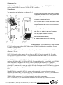
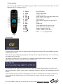
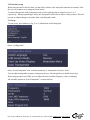
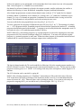
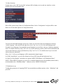
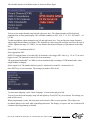
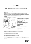
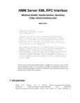
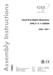
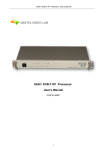
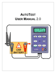
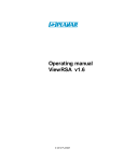
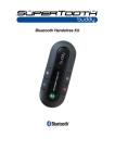
RFT-845 Twin DVB-S2/COFDM HD remux modulator User Manual RF-Tuote Oy, Telakkatie 25, 25570 Teijo, tel. +358-2736 6360, fax. +358-2-736 6360, [email protected], www.rf-tuote.fi 1. Purpose of use RFT-845 is HD compatible remux modulator designed for a processing two 8PSK/QPSK modulated satellite signals (DVB-S2) into two COFDM (DVB-T) multiplex. 2. Installation The connections and indications are shown in Fig 1. 1. Control switch to program channel 1 (left) or channel 2 (right). The switch must be set to middle position when programming is ready 2. Channel number ( CCIR) 3. Cable-TV S channel indicator led 4. The signal led shows the output channel mode or that the unit is powered 5. Signal led indicates that receiver is locked to selected transport stream 6. LNB IN (e.g through RFZ-802) 7. USB ports are for possible software update 8. RF OUT + DC IN in RFT-800 frame installation 9. DC IN (only in stand-alone installation) 10. DC OUT for next RFT-831 unit (max. 4 units in chain in stand-alone installation) 11. VIDEO/AUDIO connectors for monitoring 12. IR detector 13. CAM slot 14. Bit rate indicator. Red = overload, Green = under maximum RFT-845 can be mounted either to RFT-800 system (RFT-800 User Manual) or stand-alone. Do not cover the air passage holes. Signals from LNB are fed to IF-connectors (6) at the top of unit. Maximum total current of LNB connector is 250 mA. NOTE! LNB supply voltage must be fed only from one RFT-845 receiver to each LNB. For other receivers must be selected Power OFF (Configuration menu/LNB control mode) or use original RFZseries DC-blocked splitters. When RFT-845 is mounted for RFT-800 frame, the power voltage is supplied through active output combiner (RFC-808 or RFC-816). When RFT-845 is mounted stand-alone, power supply unit (RFP-804 or RFP-808) must be mounted to the left side of RFT-845 due to the ventilation. DC connector is connected to left side of DC connector at the bottom of unit (9). You can loop-through DC from the right side DC connector (10) to next unit with the DC cable. Maximum four RFT-845 units in chain can be supplied with one power supply (RFP-804) in stand-alone installation (max. two units with RFP802). When RFT-845 is mounted for RFT-800 system, cable to network is connected to active output combiner (RFC-808 or RFC-816). When RFT-845 is mounted stand-alone, RF OUT (8) is connected to cable network via external RF combiner (RFZ-802). VIDEO/AUDIO connectors (11) are for monitoring the unit while programming. NOTE! CA module (13) for smart card must be installed and removed only when power is OFF. RF-Tuote Oy, Telakkatie 25, 25570 Teijo, tel. +358-2736 6360, fax. +358-2-736 6360, [email protected], www.rf-tuote.fi 3. Programming The receivers and modulators are simple to program with the remote control unit (RCU-800). The main functions of RCU are shown in Fig 2. 1. MENU 2. INFO 3. OK 4. VOL 5. VOL ! 6. EXIT 7. SYS 8. F1 9. EPG 10. ¼¼ 11. ½½ 12. CH ¼ 13. CH ½ 14. UHF Main OSD menu Channel information Confirm selection Audio volume, select left (audio output only) Audio volume, select right Exit from menu Add or remove programs to output MUX BER Channel list Scroll channel list one page at a time Scroll channel list one page at a time Change a channel, select up Change a channel, select down UHF + ¼/½ = set output channel Fig 2. 3.1 Power-up At power-up this welcome screen is displayed. Main SW and user interface SW version numbers plus unit serial number are shown. When the unit is powered the display lights up showing selected output channels (Fig 1. no 2 ). The factory set channels are E40 and E42. The display is switched off after 3 minutes. Two signal led indicate that the unit is powered. The display lights up again by pressing any button of remote controller unit. Next program info for channel previously selected is displayed and the channel opened, if possible. Info shows program name, DiSEqC switch control, transponder frequency, data rate, FEC and channel video PID number. Please note that opening a channel will take longer time when a conditional access module is inserted. It is recommended to use updated smart card. If the channel list is empty, welcome screen will remain displayed. RF-Tuote Oy, Telakkatie 25, 25570 Teijo, tel. +358-2736 6360, fax. +358-2-736 6360, [email protected], www.rf-tuote.fi 3.2 First time set-up When using the unit for the first time, you must first connect video and audio connectors to monitor. After this you can continue set-up using on-screen menus. To control the unit first slide front panel switch to left or right position to control receiver 1 or 2 respectively. When programming is ready, the front panel switch must be slide to center position. This will prevent accidental changes to be made while controlling other units. 3.3 Set-up To start set-up, press Menu key (Fig 2. no 1). Main Menu will be displayed. Select “Configuration”. Select “Scan Transponder” and write the parameters of transponder and press “Scan”. You can adjust transponder frequency using numeric keys, left and right keys or double arrow keys. When using non-universal LNBs, you can adjust the local oscillator frequency values accordingly. All selectable options in “Scan Transponder” are shown below. RF-Tuote Oy, Telakkatie 25, 25570 Teijo, tel. +358-2736 6360, fax. +358-2-736 6360, [email protected], www.rf-tuote.fi It takes few minutes to scan transponder. After transponder have been scanned you can select programs from “Select Program” or “Channel List (in main menu)”. On channel list all stored channels are listed with sequence number, satellite indication (the satellite is indicated as following A=Astra, B=Hotbird), transponder frequency and band information. After channel program name on right column channel status is shown. “FTA” stands for free channel available without a Conditional Access module or a viewing card. “CA” stands for Conditional Access channel. To view a CA channel an appropriate Conditional Access Module and a viewing card will be needed. This information is only normative and can be missing in some cases. You can scroll the list using up and down arrow keys (Fig 2. no 12 or 13). To select a programs for outgoing COFDM stream press SYS key (Fig 2. no. 7). The meaning of symbols are + = FTA program selected, scrambled program selected but not opened at the headend, $ = scrambled program selected and opened at the headend, - = program is not selected (default after transponder scan). To save and exit select + or $ marked program and press OK key. NOTE! When FTA time-sharing program (e.g. regional program) is selected to outgoing mux, this same program must NOT be selected to analogue output (AV connectors). You must select also the original program ( e.g. national programs) to same mux. When time-share program is descrambled at the head end (marked with $) it must be selected to analogue output (select it and press OK) . The logical channel number (LCN) can be modified as following. Select the wanted program number (e.g. 0004) in Channel List menu. Then just press the wanted position number (e.g. 02). The set-top-box set this program to memory place no 2. NOTE! LCN setting works only in the set-top-boxes which support LCN function. The LCN selection can be canceled by typing 00. NOTE! After selecting programs go to “Modulator” menu and press OK to check the status of bit rate. “Fill” beam shows how many percentage of the maximum stream is used. It is recommendated that the stream is between 60 .. 80%. Otherwise there can be pixeling in pictures. If you want to select only one program for outgoing MUX, you can add bit rate by selecting higher FEC e.g. 1/2 or 2/3 . RF-Tuote Oy, Telakkatie 25, 25570 Teijo, tel. +358-2736 6360, fax. +358-2-736 6360, [email protected], www.rf-tuote.fi 3.4 Other functions In main menu, select “SW Version Info” and press OK to display receiver and user interface version numbers plus unit serial number info. Most of the system set-up is done in Configuration Menu. Select “Configuration” and press OK to enter. Below are all selectable options in Configuration menu. You can select the audio language in two ways. Firstly you can select from preset languages selecting “Audio Language” and using left and right arrow keys ( Fig 2. no 4 or 5) to select the language name. Secondly if your language is not among the preset languages you can freely write any 3-character language name. Use double arrow keys (Fig 2. no 10 or 11) to select character position, which will be underlined, and select needed character using up and down keys (Fig 2. no 12 or 13). Use double arrow keys to exit edit with no character underlined. Select “ALL” if all received languages will be transmitted to digital output. In “LNB Control Mode” you can select Normal or Power OFF using left and right arrow keys. In “Start-Up Video Display” menu there are options “MPEG2 SD Monitor” and “Modulator Menu”. NOTE! When MPEG-4 programs are received or scrambled channels are not descrambled (marked with +) at the headend select “Modulator Menu”. Otherwise select “MPEG2 SD Monitor”. 3.5 Modulator set-up To adjust the parameters of outgoing DVB-T stream and other modulator options, select “Modulator” and press OK. RF-Tuote Oy, Telakkatie 25, 25570 Teijo, tel. +358-2736 6360, fax. +358-2-736 6360, [email protected], www.rf-tuote.fi All selectable options of modulator menu are shown in below figure. You can select output channel using left and right arrow keys. The channel number will be displayed simultaneously on front panel display. The selectable channels are S02 - S10, 5 - 12, S11 - S41 and 21 – 69 (CCIR). To adjust modulator output attenuation use left and right arrow keys. You can fine tune output frequency when using different channel grid than CCIR. Adjustment is done using left and right arrow keys in steps of 1 MHz. Adjustment range is 4 MHz. You can monitor the adjusted frequency in parenthesis on the same line. Select DVB-T Constellation QAM 64. Select appropriate FEC. NOTE! If outgoing bitrate is less than 50% of maximum, select bigger FEC value (e.g. 1/2 or 2/3) to reach bigger bit rate. The optimum bit rate is 80% from maximum. The appropriate bandwidth 7 or 8 MHz is selected automatically according to CCIR channel table, when output channel is changed. Select output level. The number indicates gain (0= minimum level and 20 = maximum level). Press EXIT key to exit from menu. The settings you made will be saved. To select menu language, select “Menu Language” in main menu and press OK. You can select the menu language using left and right keys. Press EXIT key to exit menu. The settings you made will be saved. When programming is ready, the front panel switch must be slide to center position. This will prevent accidental changes to be made while controlling other units. The display, except two led, are switched off in 6 minutes after programming is finished. RF-Tuote Oy, Telakkatie 25, 25570 Teijo, tel. +358-2736 6360, fax. +358-2-736 6360, [email protected], www.rf-tuote.fi 4. Technical specification 8PSK/QPSK INPUT Number of channels 2 Tuners 2 Input frequency range 950 - 2150 MHz Input level -70 … -25 dBm Waveform 8PSK, QPSK (SCPC, MCPC) Symbol rate 4-45 MS/s FEC decoder Automatic Transport stream MPEG-2 ISO/IEC 13818 CI slot 2 COFDM OUTPUT Modulation IFFT 2k mode, QPSK, QAM16, QAM64 Output frequency range 114 MHz - 858 MHz Quard Interval 1/32 Max. output bit rate rate 32 Mbit/s Output level 85 - 105 dBuV Data interface 2* USB 1 Input connectors F-female 75 ohm Output connectors F-male 75 ohm Power consumption 16VDC/1,2A Dimensions Mounting W*H*D 72mm*218mm*129mm RFT-800 system, 19” rack or stand alone This symbol on the product or on its packing means that within the European Union the product must be taken to separate collection at the product-end-of life. Do not dispose of these products as unsorted municipal waste. Fore more information about where you can drop off your waste equipment for recycling, please contact your local city office, your house disposal service or the shop where you purchased the product. RF-Tuote Oy, Telakkatie 25, 25570 Teijo, tel. +358-2736 6360, fax. +358-2-736 6360, [email protected], www.rf-tuote.fi