1
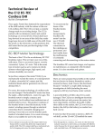
LT-3D CAD / Falcon User Manual v1.2 Edited: September 26, 2014 Table of Contents 1.0 Main Screen Layout ............................................................................................................... 5 2.0 File Menu............................................................................................................................... 6 2.1 New................................................................................................................................... 6 2.2 Open Job ........................................................................................................................... 6 2.3 Import Job ......................................................................................................................... 7 2.4 Open Auto Save Job ........................................................................................................... 7 2.5 Save Job ............................................................................................................................ 8 2.6 Import ............................................................................................................................... 8 2.6.1 2.6.2 2.7 DWG .......................................................................................................................................................8 DXF .........................................................................................................................................................8 Export................................................................................................................................ 8 2.7.1 2.7.2 2.7.3 2.7.4 2.7.5 2.7.6 2.8 3.0 DWG .......................................................................................................................................................8 DXF .........................................................................................................................................................8 Falcon Job...............................................................................................................................................8 Images ....................................................................................................................................................8 Export Full Job ........................................................................................................................................9 Email Job Files ........................................................................................................................................9 Exit .................................................................................................................................... 9 Edit Menu ............................................................................................................................ 10 3.1 Job Images ....................................................................................................................... 10 3.1.1 3.1.2 3.1.3 3.2 Setup ....................................................................................................................................................10 Taking a Picture ....................................................................................................................................10 Images ..................................................................................................................................................10 Options ........................................................................................................................... 10 3.2.1 3.2.2 3.2.3 3.2.4 3.2.5 3.2.6 3.2.7 3.2.8 3.2.9 3.2.10 General - Snap to Point Distance .........................................................................................................11 Drawing – Background Color ................................................................................................................11 Drawing – View Box Size ......................................................................................................................11 Drawing – Font Size ..............................................................................................................................11 Drawing – Line Width ...........................................................................................................................11 Export – Remove Control Points ..........................................................................................................11 Email.....................................................................................................................................................11 Units – Linear Unit of Measure ............................................................................................................11 Device – Laser Connection ...................................................................................................................11 Advanced – Set Advanced Options..................................................................................................11 3.3 Job Details ....................................................................................................................... 11 3.4 Undo ............................................................................................................................... 11 3.5 Redo ................................................................................................................................ 12 3.6 Choose Layer ................................................................................................................... 12 3.6.1 3.6.2 3.6.3 Add Layer .............................................................................................................................................12 Edit Layer..............................................................................................................................................12 Delete Selected Layer...........................................................................................................................12 3.7 Revise Layer..................................................................................................................... 13 3.8 Edit Default layer ............................................................................................................. 14 2|Page 3.8.1 3.8.2 3.8.3 4.0 Add Layer .............................................................................................................................................14 Edit Layer..............................................................................................................................................14 Delete Selected Layer...........................................................................................................................14 CAD Menu ........................................................................................................................... 15 4.1 Set Plane ......................................................................................................................... 15 4.1.1 4.1.2 4.1.3 4.1.4 4.1.5 4.1.6 Keep Adding Planes ..............................................................................................................................15 Plane Type – Three Point Plane............................................................................................................15 Name ....................................................................................................................................................16 Name ....................................................................................................................................................16 Existing Plane .......................................................................................................................................16 Set Existing Plane .................................................................................................................................16 4.2 Reposition Laser .............................................................................................................. 16 4.3 Combine Pages ................................................................................................................ 17 4.4 Erase ............................................................................................................................... 18 4.5 Extend ............................................................................................................................. 18 4.6 Fillet ................................................................................................................................ 19 4.7 Offset .............................................................................................................................. 20 4.8 Change Point ................................................................................................................... 21 4.9 Draw Entity...................................................................................................................... 22 4.10 Add Text .......................................................................................................................... 23 4.11 Intersect Plane ................................................................................................................. 24 4.12 Connect Point to Plane ..................................................................................................... 25 4.13 Import DXF ...................................................................................................................... 26 4.14 Distance .......................................................................................................................... 27 4.15 Dimension ....................................................................................................................... 27 5.0 Laser Menu .......................................................................................................................... 29 5.1 Connect to Laser .............................................................................................................. 29 5.2 Turn Laser On .................................................................................................................. 29 5.3 Start New Line ................................................................................................................. 30 5.4 Turn Laser Off .................................................................................................................. 30 5.5 Take Measurement .......................................................................................................... 30 5.6 Laser Control ................................................................................................................... 30 5.7 Ruler Point....................................................................................................................... 30 6.0 View Menu .......................................................................................................................... 31 6.1 Show Top......................................................................................................................... 31 6.2 Show Default View........................................................................................................... 31 6.3 Show Bottom ................................................................................................................... 31 7.0 7.1 ORD Menu ........................................................................................................................... 32 Enter ORD Mode .............................................................................................................. 32 3|Page 7.2 Add Walls ........................................................................................................................ 32 7.3 Add Windows .................................................................................................................. 34 7.4 Add Doors........................................................................................................................ 35 7.5 Add Power Outlet / Phone Line / Power Switch / Pipe Line ............................................... 36 7.6 Saving ORD Files .............................................................................................................. 37 8.0 Help Menu ........................................................................................................................... 38 8.1 License Keys..................................................................................................................... 38 8.2 About .............................................................................................................................. 38 8.3 Email Developer............................................................................................................... 38 9.0 General information............................................................................................................. 39 9.1 Warranty Information ...................................................................................................... 39 9.2 Laser Safety Guidelines .................................................................................................... 39 9.3 Using the Computer for Other Programs ........................................................................... 39 9.4 Windows 8....................................................................................................................... 39 9.5 Cleaning / General Care and Storage ................................................................................ 40 9.6 LT-2D3D Laser Templator Specifications ........................................................................... 40 9.7 Training Videos ................................................................................................................ 40 10.0 Technical Information .......................................................................................................... 41 10.1 Accuracy and Distance Specifications................................................................................ 41 10.2 Storage and Operating Temperatures ............................................................................... 41 10.3 Laser Specifications .......................................................................................................... 41 11.0 Contact Information ............................................................................................................. 42 12.0 Registration ......................................................................................................................... 43 4|Page 1.0 MAIN SCREEN LAYOUT A – File Menus B – Toolbar C – Pages (clicking plus adds new page) D – Zoom on box E – Zoom in and out F – Pan tool G – Rotate tool H – Zoom Fit I – Rotate Box J – Current drawing orientation K – Version information L – Laser status M – Job Name N – Status updates O – Drawing mode selector (Line, Arc, Circle, Point) and Selected Layer (will be colored based on Layer color) 5|Page 2.0 FILE MENU 2.1 New Clears all current job data and starts with a blank canvas. 2.2 Open Job Opens an existing saved job from the job database. Displays a list of jobs that exist in the database ordered by the last time the job was updated. There are also counts for the number of pages, images and entities (lines, arcs, circles and points) in the job. 6|Page 2.3 Import Job Opens a .falcon file. This is used to transfer job data between computers. 2.4 Open Auto Save Job Similar to Open Job, this displays a list of auto saved files that can be used to recover unsaved data. Jobs are automatically saved every 3 minutes. 7|Page 2.5 Save Job Allows the existing job and all associated data (pages, images, job info and layers) to be saved to the database. 2.6 Import 2.6.1 DWG Opens an existing DWG file and adds to page 1. 2.6.2 DXF Opens an existing DXF file and adds to page 1. 2.7 Export 2.7.1 DWG Exports the current page as a DWG file. This is used to transfer to a plotter, CNC, waterjet or other fabrication machinery. 2.7.2 DXF Exports the current page as a DXF file. This is used to transfer to a plotter, CNC, waterjet or other fabrication machinery. 2.7.3 Falcon Job Exports the job as a .falcon file. This is used to transfer job data between computers. 2.7.4 Images Exports the current page as a PNG (image) file. This is used for recording screenshots of the way a job looks for visual reference. 8|Page 2.7.5 Export Full Job Creates a directory and exports all data for the job. This includes a DWG, DXF and PNG file per page, a .falcon job file and any images captured via the webcam. Enter a Job Name and choose the directory you want to export the job to. Then press OK. 2.7.6 Email Job Files Emails all or some (user choice) Export Full Job files to a recipient. Enter a To Address, Job Name, Subject, Message and check the files you want sent. Then press OK. 2.8 Exit Closes the application 9|Page 3.0 EDIT MENU 3.1 Job Images Allows for capture of images that will be stored in the job from any attached webcam. These images will appear when using Export Full Job and Images and will be embedded in the .falcon file. 3.1.1 Setup The first time you open this you will need to choose the Camera, Resolution and Frame Rate. 3.1.2 Taking a Picture Press Start. Once you have the camera pointed at the subject you want to photograph press Take Image to capture it. 3.1.3 Images Clicking the Images radio button will bring up a view of saved images for that job. You can add a description for each image and scroll through all captured images. 3.2 Options Allows settings for the application to be changed. 10 | P a g e 3.2.1 General - Snap to Point Distance When a measurement is taken the application searches through existing measurements and chooses the closest measurement that is less than this distance and will be used instead of the currently captured point from the laser. This allows for corners to be snapped together. 3.2.2 Drawing – Background Color Changes the background color of the drawing. Supported colors are black, white, blue and none. 3.2.3 Drawing – View Box Size Size of the View Box and Menus in the upper right corner of the drawing. 3.2.4 Drawing – Font Size Changes the font size throughout the application. 3.2.5 Drawing – Line Width Changes the line width displayed on the drawing to allow for easier selecting of lines, arcs and circles. 3.2.6 Export – Remove Control Points When creating a DXF or DWG file, if this is checked, control/construction points will not be created for measured points that were taken by the laser or the snap points of the lines (end and center points), arcs (end and center points) or circles (points at 12, 3, 6 and 9 o’clock). 3.2.7 Email If you choose to email your templated files back to your shop while you are at a jobsite, this is where you will set up your email configurations. The email settings are standard settings so please look at your personal email account settings and copy that information over to these forms. If you are unsure of your email settings, please contact your email/website/internet provider to obtain them. There are many email providers out there; we cannot keep track of everyone's individual settings. 3.2.8 Units – Linear Unit of Measure Allows the user to set the units of measure to use within the application. 3.2.9 Device – Laser Connection Allows the user to select which type of laser to connect to (LT-2D3D Laser Templator or 3D Disto). 3.2.10 Advanced – Set Advanced Options Allows for settings to be added that Laser Products can implement by unlocking features as they become available for specific industries. 3.3 Job Details Allows for input of details pertaining to the job like names, phone numbers and addresses. 3.4 Undo Undoes the last change to the job. 11 | P a g e 3.5 Redo Redoes the last change to the job that was undone. 3.6 Choose Layer Switches the layer that will be applied to new entities. 3.6.1 Add Layer Add a new layer to this specific job. 3.6.2 Edit Layer Allows attributes for the selected layer to be modified for this specific job only. Name: Name of the layer (will appear in the lower right of the application when the layer is selected). Color: The color to draw entities within that layer. Line Type: ByLayer or ByEntitiy. This is a CAD setting that will be transferred to the DXF and DWG files. Dashed: Determines if the lines should be drawn dashed or solid. Visible: Determines if the layer is visible or not on the drawing. 3.6.3 Delete Selected Layer Removes the selected layer from this specific job only. 12 | P a g e 3.7 Revise Layer Allows existing entities to have their layer changed for this specific job only. 1. Click Revise Layer and Choose Layer you want by clicking OK. 2. Click on the entities you want to change. 13 | P a g e 3.8 Edit Default layer Edits the list of layers that will be present when a new job is created. This will have no effect on the current layers within the job on previous jobs. 3.8.1 Add Layer Adds a new layer. 3.8.2 Edit Layer Allows attributes for the selected layer to be modified. Name: Name of the layer (will appear in the lower right of the application when the layer is selected). Color: The color to draw entities within that layer. Line Type: ByLayer or ByEntitiy. This is a CAD setting that will be transferred to the DXF and DWG files. Dashed: Determines if the lines should be drawn dashed or solid. Visible: Determines if the layer is visible or not on the drawing. 3.8.3 Delete Selected Layer Removes the selected layer. Note: Add Layer and Edit Layer leverages the same screen as Add Layer and Edit Layer from the Choose Layer screen. When modifying layers here though, it will change the settings globally in the program where as If you do it in Choose Layer, it is only changing in that specific job. 14 | P a g e 4.0 CAD MENU 4.1 Set Plane Allows a plane(s) to be created or set active. Planes can be used to flatten points while measuring. There are several purposes to do this: 1. Capture points normalized to the plane: For example a plane can be established on a counter top and then points can be captured along the front of the existing cabinets or wall. The captured point from the laser will be then captured on the closest point on the plane (points are flattened to one surface). 2. Offset arcs and lines. 3. Create dimensions. 4. Determine points and lines from the intersections of the planes. 4.1.1 Keep Adding Planes Keeps the user in the Set Plane function so planes can be established for several walls/surfaces at the same time. 4.1.2 Plane Type – Three Point Plane Three points are captured to create a plane. To set a Three Point Plane: 15 | P a g e 1. 2. 3. 4. 5. 6. 7. 8. 4.1.3 Choose Three Point Plane in Plane Type. Turn the laser on and move the laser to the first point. Click Take Measurement. Move the laser to the second point. Click Take Measurement. Move the laser to the third point. Click Take Measurement. A yellow triangle will indicate a plane has been established. Name A perfectly horizontal plane will be established based on a single point. To set a One Point Plane: 1. 2. 3. 4. 4.1.4 Choose One Point Plane in Plane Type. Turn the laser on and move the laser to the first point. Click Take Measurement. A yellow triangle will indicate a plane has been established. Name The name of the plane that will be created. 4.1.5 Existing Plane Allows the user to switch to a previously established plane. 4.1.6 Set Existing Plane Sets the current plane to the plane selected in the Existing Plane drop down. 4.2 Reposition Laser Allows the user to pick up and move the laser to a new physical location and then continue capturing points. To reposition the laser: 1. Determine 3 points that can be viewed from both the current laser location and the location the laser will be moved to. 2. Click Reposition Laser. 16 | P a g e 3. 4. 5. 6. 7. 4.3 Turn the laser on and capture point 1, 2, and 3. Pick up the laser and move it to the new location. Level the laser. Capture point 1, 2, and 3 in the exact same order. Continue to capture points from the new location. Combine Pages Allows two pages to be combined based on three reference points that exist on each page. 1. Go to the first page with the 3 common points. 2. Click CAD / Combine Pages. 3. Click on reference point 1, 2 and 3. 4. Go to the second page with the 3 common points. 5. Click on reference points 1, 2 and 3 in the same order. 6. Entities from the first page will be inserted into the second page. 17 | P a g e 4.4 Erase Erases an entity. Click on the entity that you wish to erase. 4.5 Extend Extends a line/arc to its intersection with another line/arc. To extend: 1. Click CAD / Extend. 2. Click a line or arc to extend to. 18 | P a g e 3. Click the line or arc to extend. 4.6 Fillet Performs a fillet operation (sharp, chamfer or radius) between a line or arc and another line or arc. To fillet: 1. Click CAD / Fillet. 2. Set the Fillet Type (Radius, Chamfer or Sharp) along with the Amount. 3. Click the first line or arc to fillet. 19 | P a g e 4. Click the second line or arc to fillet. 4.7 Offset Offsets a line or arc along a plane. A plane must be established before Offset can be used. To offset: 1. Click CAD / Offset. 2. Choose the Amount to offset. 20 | P a g e 3. Click a line or arc. 4. Click on the offset that you wish to perform. 4.8 Change Point Allows the end point of an arc or line to be snapped to a different existing point. To change a point: 1. Click CAD / Change Point. 21 | P a g e 2. Click on the line or arc close to the end point that you want to move. 3. Click on the end point that you want it to connect to. 4.9 Draw Entity Use existing points to draw a line, arc or circle. To draw and entity: 1. Click CAD / Draw Entity. 22 | P a g e 2. Choose the Entity Type Line (two points), Arc (three points) or Circle (three points). 3. Click on two points to draw a line, or 3 points to draw an arc or circle. After the last point is clicked, the entity will be created. If Keep Last Point is checked, the last point will be reselected for the next entity to create. 4.10 Add Text Add text to a point. To add text: 1. Click CAD / Add Text. 2. Type the text and choose the Size. 23 | P a g e 3. Click on a point to add the text. 4.11 Intersect Plane Allows points and lines to be created based on the intersection of planes previously established. In the following example we first went into Set Plane and created 6 planes measuring 3 points for each plane. Those planes were the back wall, front wall, right wall, left wall, ceiling, and floor. Using those 6 planes an outline of the room can be created. 1. Click CAD / Intersect Plane. 24 | P a g e 2. Select all planes from the drop downs. 3. Click Create Points. 4. Click Create Lines. 4.12 Connect Point to Plane Create points or lines based on the intersection point to a plane to measure the distance. In the following example a horizontal plane (1 point) is established along the wall and several points are taken along the floor to determine the high and low points of the flooring. 1. Click CAD / Connect Point to Plane. 2. Choose the Existing Plane. 25 | P a g e 3. Click on a point to see its elevation in relation to the plane. 4.13 Import DXF Allows a DXF to be imported into the current drawing. Currently only lines, arcs, circles and points are supported. Blocks and Polylines are not supported as of yet. 1. Click CAD / Add DXF. 2. Choose the DXF file by clicking the Choose File button and selecting the file. 3. Click Two Point Angle if snapping to a counter top edge. 26 | P a g e a. Click two points on that edge and an angle of that line will be filled in. b. The first point clicked will highlight in yellow. 4. Click on the line where you want the DXF to be placed. a. The DXF will snap to the closest point (end, mid or intersection). 4.14 Distance Calculate the distance between points on the drawing. 1. Click CAD / Distance. 2. Click on two points. 4.15 Dimension Add a dimension to the current drawing along a previously established plane. 1. Click CAD / Distance. 2. Choose the Plane, Offset Amount and Text Size. 27 | P a g e 3. Click the two points to dimension. 4. Click on the dimension (between the two displayed) to add it. 28 | P a g e 5.0 LASER MENU 5.1 Connect to Laser Establish a connection to selected laser type chosen in the Options menu. When the Connect to Laser button is clicked and a connection is successfully established, the status bar at the bottom will indicate the connection status. 5.2 Turn Laser On Turns the laser beam on. 29 | P a g e 5.3 Start New Line Clears any pending points and turns the laser beam on. 5.4 Turn Laser Off Turns the laser beam off. 5.5 Take Measurement Captures a measurement from the laser. 5.6 Laser Control Pops up a small opaque control that makes it easier to Turn Laser On, Start New Line, Turn Laser Off and Take Measurement. 5.7 Ruler Point Allows a single unseen point to be measured using a well-known (supplied by Laser Products Industries) ruler that the user collects two points from. 30 | P a g e 6.0 VIEW MENU 6.1 Show Top Changes the current view to a top down view. 6.2 Show Default View Changes the current view to an isometric view. 6.3 Show Bottom Changes the current view to a bottom up view. 31 | P a g e 7.0 ORD MENU ORD mode provides a structured set of flows to quickly template a set of walls that allows for export to the in the Cabinet Vision ORD format. ORD mode will not be available until Laser Products is contacted and an additional license key is provided to enable the features of ORD mode. Once enabled an additional menu will be available titled ORD. 7.1 Enter ORD Mode Captures the floor and ceiling. The first step in creating an ORD drawing is establishing the floor and ceiling. This will let the application know how tall walls need to be. After clicking Enter ORD Mode turn the laser and measure a point on the floor and then a point on the ceiling. Enter ORD Mode will be exited indicating that this operation completed successfully. 7.2 Add Walls Allows walls to be added to the drawing. Requires Enter ORD Mode to be completed successfully. This must be done clockwise or the Cabinet Vision software will not recognize the relationship between walls. 1. Indicate the thickness of the wall 2. Measure two points on the wall. While looking directly at the wall the first point measured will be on the left. Once two points are measure a wireframe of that wall will be shown. 3. Next move the laser to the second wall and again measure a point on the left then the right. 32 | P a g e 4. Repeat for all the connected walls If the last wall draw intersects with the first wall draw press the Finish Walls button and the First and Last wall will automatically be joined within the application boxing off the room. 33 | P a g e 7.3 Add Windows Allows windows to be added to a wall. Requires Add Walls to be completed successfully. 1. Click the line representing the floor or the line representing the ceiling of the wall to add the window to. 2. Measure the furthest left point 3. Measure the top most point and the furthest right point. 34 | P a g e 4. Measure the bottom most point. When the bottom point is taken a window will be drawn based on the measured points. 7.4 Add Doors Allows doors to be added to a wall. Requires Add Walls to be completed successfully. 1. Click the line representing the floor or the line representing the ceiling of the wall to add the window to. 2. Measure the furthest left point, top most point. 35 | P a g e 3. Measure the furthest right point. 7.5 Add Power Outlet / Phone Line / Power Switch / Pipe Line The Add Power Outlet, Add Phone Line, Add Power Switch, Add Pipe Line allow structural elements to be located on the drawing and transferred to Cabinet Vision. Requires Add Walls to be completed successfully. These operations all work in the exact same manner. 1. Click the floor or ceiling line on the wall that contains the structural element. 2. Measure the point indicating the middle of that structural element. The structural element will be shown on the drawing as a single point. In the above example a power outlet was added just to left of the door. 36 | P a g e 7.6 Saving ORD Files After entering ORD mode and adding walls, doors, windows and structural elements an additional file will be shown when saving a Job. The file type will be Cabinet Vision ORD File and the Name will be <Page>.ord. This file can then be opened in the Cabinet Vision application. 37 | P a g e 8.0 HELP MENU 8.1 License Keys Set license keys within the application. When the application installs, only the Help menu is available. You will open the Help menu and email the Registration Key to us at [email protected]. We will reply back with the License Key that will unlock the software. 8.2 About Displays information about the application. 8.3 Email Developer Sends the developer an email with a screen shot of the application and any notes that the user would like to provide, along with additional debugging information. 38 | P a g e 9.0 GENERAL INFORMATION 9.1 Warranty Information We offer a 1 year warranty on the LT-2D3D Laser Templator from the date of purchase. After the first year, you have the option of renewing your warranty for $500.00. The original and extended warranty includes the following: • Extended warranty on the LT-2D3D unit with the exception of the tablet and misuse/abuse of the laser. • Laser Products will provide a loaner LT-2D3D and/or tablet computer should your unit need to be sent in for repair. All repair costs on the tablet are the responsibility of the owner. • Free upgrades to software and minor mechanical updates. • Free target package. Each year Laser Products will send a complete target package if requested. • Free yearly check-up. This consists of a thorough inspection of the unit including cleaning the lenses, testing the batteries, inspecting for worn or damaged components, etc. (Loaner units are not included as part of this service) • Discounted in house training at Laser Products. This entitles you to one day of training each year at the Laser Products office in Romeoville, IL at half price. This is in addition to the initial training included with the purchase of a new LT-2D3D. 9.2 Laser Safety Guidelines These guidelines are for your own protection and that of others around you. Lasers have a unique set of dangers not present with other equipment common at work or at home. 9.3 Like most laser point devices, it is important to exercise caution with operating this device. Never look into the beam of this or any other laser. This also includes pointing it at others around you. Always turn off the laser beam when it is not being used to avoid accidental eye exposure. When adjusting or aligning a laser, beware of reflections from all surfaces. Never randomly aim a laser at other people. Although this laser is low power, direct eye contact should always be avoided. This is a tool just like any other power tool on a job site and should be treated that way. Instruct anyone else with you as to the hazards of laser light and make sure they understand all of these guidelines. Those with you may actually be in MORE danger because you will know what to expect and what to avoid unlike them. This product conforms to IEC Regulations Using the Computer for Other Programs The computer that comes with this laser runs a full installation of Windows and can run most Windows compatible programs. However, installing any programs other than those that are installed at the time you receive it can alter or hinder operations and functionality. We strongly suggest you only use this tablet for templating and other related functions. 9.4 Windows 8 Microsoft changed the user interface of Windows 8 from the previous version of Windows 7. We have installed a program called Classic Shell to every tablet that boots the computer into the legacy Desktop like all previous versions of Windows has done. We have also replaced the Start Menu which was removed by Microsoft because we felt that having a consistent user interface across all versions of Windows on every tablet makes it easier for customers to transition to new hardware as well as support it. If you would like more information on Windows 8 and how to navigate the new User interface please visit the following page for an overview: http://windows.microsoft.com/en-US/windows8/basics#1TC=t1 39 | P a g e 9.5 Cleaning / General Care and Storage The LT-2D3D is a precision measurement tool and needs to be treated with care. Please follow the guidelines below. 9.6 Make sure the lens of the laser is clean before starting every job. Finger prints and smudges can affect accuracy of the laser. Handle the tablet PC with care. This is a computer and like all computers, if they are treated roughly, the internal components or outside casing can be damaged. o As stated above in the warranty, misuse / abuse is not covered in the warranty which include but are not limited to: Cracked / broken screens. Dropping any part of the device leading to cracked outside housing or damaged internal components. LT-2D3D Laser Templator Specifications The LT-2D3D software was designed to be used on any current Windows computer but will run on both Windows 7 and 8. We have heard of customers using it on Windows Server 2000, 2003 and 2008 however we have not tested this nor do we support it. If you choose to install the software on a server, we will offer no support. 9.7 Training Videos With the purchase of every LT-2D3D Laser Templator, training videos are included. Please watch those videos to learn how to use this digital templating system properly. This user manual is meant to be a quick reference and used in conjunction with the videos but is not meant to replace watching those training videos. They can be viewed on our website as well at http://laserproductsus.com/videos/ 40 | P a g e 10.0 TECHNICAL INFORMATION 10.1 Accuracy and Distance Specifications Accuracy of +/- 1/16" up to 50 feet on industry standard surfaces Capable of measuring up to 200 feet to industry standard surfaces Capable of measuring up to 600 feet using an appropriate target under ideal conditions 10.2 Storage and Operating Temperatures Storage: -4 °F to 113°F (-20°C to 45°C) (LT-2D3D Laser Templator) Operation: 32°F to 113°F (0°C to 45°C) (LT-2D3D Laser Templator) Storage: -4 °F to 95°F (-20°C to 45°C) (Tablet PC) Operation: 32°F to 95°F (0°C to 45°C) (Tablet PC) Minimum temperature required to charge the batteries: 32°F (0°C) 10.3 Laser Specifications 635nm <1mW Class 2 Laser Product Complies with 21 CFR 1040.10 and 1040.11 except for deviations pursuant to Laser Notice no. 50, dated May 2001, with IEC 60825-1 (2001) and EN 60825-1. 41 | P a g e 11.0 CONTACT INFORMATION Laser Products Industries 1344 Enterprise Dr. Romeoville, IL 60446 USA P: 630-679-1300 F: 630-679-1356 http://laserproductsus.com [email protected] Countertop, Glass Industry Matt Thomson – 630-390-0439 – North East – (CT, IN, KY, MA, MD, ME, MI, NH, NJ, NY, OH, PA, RI, VT, WV) Matt Drnec – South East – (AL, SC, FL, AR, GA, LA, MS, NC, TN) JT Hoffmann – 630-679-1300 – Mid West – (IL, IA, KS, MN, MO, ND, NE, OK, SD, TX, WI) Jeff Larson – 303-378-3839 – West – (AZ, CA, CO, ID, MT, NV, OR, UT, WA, WY) Aatif Markar – 647-221-0467 – Canada and Middle East Carl Sharkey – +44 (0) 1274 412597 – Europe/Russia Industrial Fabric Industry Drew Thornton – 256-595-9697 – Entire United States 42 | P a g e 12.0 REGISTRATION In order to service your laser, we need to make sure we have all of your company information. Please take a moment to fill out the information below so that we can better understand your company and serve your needs. This can be faxed (630-679-1356), emailed ([email protected]) or mailed to us (1344 Enterprise Dr., Romeoville, IL 60446) General Information Company Name: ___________________ Owner: ___________________ Templator’s Name(s): _______________________________________________________________________________ Address: ______________________________________ City: ___________________ State: ____ Zip: _________ Phone: ___________________ Fax: ___________________ Website: ______________________________________ Email: ______________________________________ LT-55 XL/LT-2D3D Serial Number: ___________________ Fabrication Information (Please circle all that apply) Production Information: Automated Plant Fab Center CNC Router CNC JetSaw Saw Outsource Fabrication Training Facility CNC Saw CNC WaterJet Bridge Kitchens/Jobs Per Week: ____ CAD Experience: Beginner Intermediate Advanced Associations you are a member of: IFAI AWFS ISFA MIA NKBA Other: ___________________ SFA WFCA Other Digital Templating Products Used: ________________________________________________________________ 43 | P a g e