1
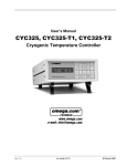
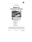
Lake Shore Model 460 Gaussmeter User’s Manual Line Cord Input Power Switch O=Off, l=On Screwdriver Slot Fuse Drawer LINE 10% +5% Voltage 50 60 Hz 50 VA MAX 120 FUSE DATA 100 / 120 V 1.0 A 0.25 x 1.25 in. T 220 / 240 V 0.5 A 5 x 20 mm T F-460-6-1.eps Figure 6-1. Power Fuse Access 6.4 FUSE REPLACEMENT Below is the procedure to remove and replace a line fuse. There are two basic power configurations: U.S. and International. Units produced for use in the U.S. have a single fuse on the hot. Units produced for International use have a double fuse for the hot and neutral. To change line input from the factory setting, use the appropriate fuse in the connector kit shipped with the instrument. Test fuse with ohmmeter. Do not rely on visual inspection of fuse. WARNING: To avoid potentially lethal shocks, turn off gaussmeter and disconnect it from AC power before performing these procedures. CAUTION: For continued protection against fire hazard, replace only with the same fuse type and rating specified for the line for the line voltage selected. 1. Locate line input assembly on the instrument rear panel. See Figure 6-1. 2. Turn power switch Off (O). 3. Remove instrument power cord. 4. With a small screwdriver, release the drawer holding the line voltage selector and fuse. 5. Remove existing fuse(s). Replace with proper Slow-Blow fuse ratings as follows: 100/120 V 1 A T 250 V 0.25 x 1.25 inches 220/240 V 0.5 A T 250 V 5 x 20 mm 6. Re-assemble line input assembly in reverse order. 7. Verify voltage indicator in the line input assembly window. 8. Connect instrument power cord. 9. Turn power switch On (l). Service 6-3