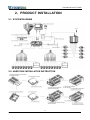
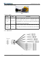
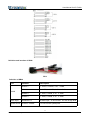
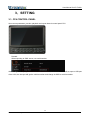
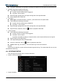
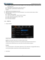
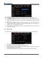
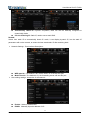
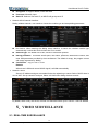
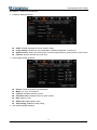
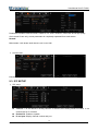
1
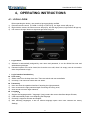
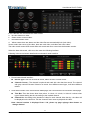
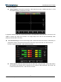
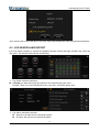
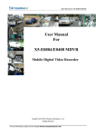
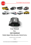
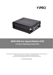
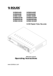
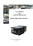
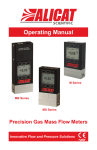
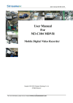
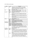
User Manual for X7-E1608 User Manual For X7-E1608 MDVR Mobile Digital Video Recorder Copyright 2013-2015, Streamax Technology Co., Ltd All Rights Reserved 1 For more information, please visit our website www.en.streamax.com User Manual for X7-E1608 Notice The information in this manual was current when published. The manufacturer reserves the right to revise and improve its products. All specifications are therefore subject to change without any notice. The purpose of this manual is to kindly aid the user for the operation for our MDVR. The user should have a basic understanding of computer operation and basic knowledge of how to connect peripherals and make some settings. Copyright Under copyright laws, the content of this manual may not be copied, photocopied, reproduced, translated or reduced to any electronic medium or machine- readable form, in whole or in part, without prior written consent of Streamax Technology Co., Ltd (Copyright 2013-2015) 2 For more information, please visit our website www.en.streamax.com User Manual for X7-E1608 Guarantee & Warnings 1) Electrical Apparatus Safety All installation and operation should comply with local electrical safety norms. 2) Transportation In the process of transportation, storage and installation, please avoid heavy stress, violent vibration, impact and water splashing. 3) Installation Install the equipment in accordance with the requirements, handle carefully. Do not heavily press the equipment before the MDVR installation is finished. 4) Requirements on Engineers & Technicians All the work of checking and maintenance should be done by qualified technicians and engineers. We do not undertake any responsibility caused by unauthorized modifications. 5) Requirements on Environment The equipment should be installed and stored in a cool and dry place, away from direct sunlight, flammable or explosive substances, etc. Keep gaps not less than 3cm around the device to facilitate ventilation for cooling. 6) Accessories Make sure to use accessories from the manufacturer recommended in the attachment. Insulate circuit ground and metal shell for all the peripherals. Before installation, please open the package and ensure that all parts are included. If there are any problems, please contact us as soon as possible. Description Term Description Term Description MDVR Mobile Digital Video Recorder LAN LAN Network FPS Picture Frames Per Second MPEG Picture Format GPS Specially for Antenna of GPS System TCP/IP TCP/IP Protocol HDD Hard Disk for Recording USB USB Flash Interface IR Remote Control IR Receiver DB44 A/V Input, Output.IO/ALARM Output DB26 Alarm Input/RS232/RS485 UPS Power to Switcher and MDVR 3 For more information, please visit our website www.en.streamax.com User Manual for X7-E1608 Content 1. PRODUCT CHARACTERISTICS................................................................................................................... 6 1.1. OVERVIEW.........................................................................................................................................6 1.2. FEATURES......................................................................................................................................... 6 1.2.1. HARDWARE FEATURES:....................................................................................................... 6 1.2.2. SOFTWARE FEATURES:........................................................................................................ 6 1.3. OPTIONAL ACCESSORIES:........................................................................................................... 7 1.3.1. POE SMART SWITCH..............................................................................................................7 1.3.2. UPS.............................................................................................................................................. 9 1.4. X7-E1608 SPECIFICATIONS........................................................................................................ 10 1.5. EXTERNAL INTERFACE................................................................................................................11 2. PRODUCT INSTALLATION........................................................................................................................... 13 2.1. SYSTEM DIAGRAM........................................................................................................................13 2.2. HARD DISK INSTALLATION INSTRUCTION............................................................................ 13 2.3. EXTERNAL WIRE DIAGRAM........................................................................................................14 2.3.1. DB44 CABLE............................................................................................................................14 2.3.2. DB26 CABLE............................................................................................................................16 2.3.3. POWER CABLE.......................................................................................................................18 2.3.4. GPS AND GPRS ANTENNA..................................................................................................18 2.3.5. ALARM INPUT / OUTPUT..................................................................................................... 19 3. SETTING...........................................................................................................................................................20 3.1. CP4 CONTROL PANEL..................................................................................................................20 4. OPERATING INSTRUCTIONS..................................................................................................................... 21 4.1. LOCAL LOGIN..................................................................................................................................21 4.2. RECORD SEARCH AND EXPORT:............................................................................................. 22 4.3. LOG SEARCH AND EXPORT.......................................................................................................25 4.4. SYSTEM STATUS........................................................................................................................... 26 4.5. BASIC SETUP..................................................................................................................................28 4.5.1. REGISTER INFOMATION (SETUP VEHICLE INFORMATION).....................................28 4.5.2. TIME SETUP............................................................................................................................ 29 4.5.3. START UP.................................................................................................................................30 4.5.4. USER SETTING...................................................................................................................... 31 4.5.5. NETWORK SETTINGS.......................................................................................................... 32 5. VIDEO SURVEILLANCE.................................................................................................................................34 5.1. REAL-TIME SURVEILLANCE....................................................................................................... 34 5.2. RECORD...........................................................................................................................................36 5.3. IPC SETUP....................................................................................................................................... 38 5.4. DATA COLLECTION........................................................................................................................39 5.4.1 GENERAL................................................................................................................................. 39 5.5. ALARM.............................................................................................................................................. 40 5.5.1 GENERAL................................................................................................................................. 40 5.6. MAINTENANCE............................................................................................................................... 42 5.6.1 CONFIGURATION...................................................................................................................43 4 For more information, please visit our website www.en.streamax.com User Manual for X7-E1608 5.6.2 5.6.3 5.6.4 5.6.5 DATA EXPORT.........................................................................................................................43 UPGRADE................................................................................................................................ 44 STORAGE.................................................................................................................................44 DEFAULT.................................................................................................................................. 45 5 For more information, please visit our website www.en.streamax.com User Manual for X7-E1608 1.PRODUCT CHARACTERISTICS 1.1. OVERVIEW X7-E1608 is a cost effective and function-extensive device specially designed for Mobile Video surveillance and intelligent dispatch. It adopts high speed processor and built-in operating system, combining with H. 264 video compression / decompression technology, 4G/3G network technology, GPS locating technology and WIFI technology. It can realize 720P high definition, WD1, WHD1, WCIF, D1, CIF, HD1, CIF video recording and vehicle driving information recording, as well as remote video upload. With center software it also achieves alarm linkage central monitoring, vehicle intelligent dispatching management and playback analysis based on central database. It is powerful with strong anti-vibration, totally metal appearance design, flexible installation, easy maintenance and high reliability. 1.2. FEATURES 1.2.1. HARDWARE FEATURES: 1) All the modules are connected with exquisite connectors, supporting quick disconnection, which is safe and easy to maintain; 2) Supports DC8~36V wide voltage output. There are protection for over voltage, under voltage, short circuit and over current; 3) Supports dual 2.5" SATA hard disks of large-capacity; 4) Built-in mechanical anti-vibration technology; 5) Adopts rich interfaces: 2xDB44, 1xserial ports (DB26), 1xCP4 aviation interface, 1xUSB, 1xfan connector, 2x RJ45, 1xpower aviation interface and 1x3Pin debugging serial port; 6) Convenient operation: CP4 touch panel, remote control, mouse, keyboard, PTZ controller are optional. It can even equips with a special extension cable for remote control; 7) Built-in wireless module: Built-in GPS module, 4G/3G (FDD-LTE/TDD-LTE/EVDO/TD-SCDMA/WCDMA); 8) Aviation interface: It adopts professional aviation interface with waterproof and anti-vibration ability. 1.2.2. SOFTWARE FEATURES: 1) 24-hour single-file recording mode. Time line mode playback, makes the operation more convenient; 6 For more information, please visit our website www.en.streamax.com User Manual for X7-E1608 2) Supports dual streams for main/sub stream recordings and mirror recording; 3) Built-in H.264 codec, user can manually configure the video coding attributes 4) A series of synchronous operation: Information record, recording playback, file backup, network transmission, etc.; 5) Supports multiple languages; 6) Adapts dynamic coding technology to adjust the dynamic change of 4G/3G network bandwidth and ensure the fluency of 7) monitoring video; Multi-information display: vehicle number, time/date information, channel information, alarm information, GPS information, speed information, etc. User can set video recording overlay and information record; 8) Supports Multi-recording modes: vehicle switch recording, timing switch recording, manual recording, alarm recording, and latent shutdown recording, etc.; supports continuous recording and loop recording; supports power protection to ensure that the last video data is not lost; 9) Local recording: 720P/WD1/WHD1/WCIF/D1/HD1/CIF resolution optional; 10) Driving record: provides statistics on speed, turning, brake, reverse, opening door, etc.; 11) Network function: supports break point uploading continually, which can realize the remote video surveillance, video download, remote alarming and network timing of the equipment, network setting and remote upgrade, etc.; 12) High-speed backup: supports high-speed backup through USB2.0, as well as built-in and external SD cards; 13) Device upgrade: upgrade all items that can be upgraded at one time; 14) Alarm linkage: supports linkage switch value output, image display, etc.; 15) Storage format: formats device hard disk and external USB devices and SD cards. 1.3. OPTIONAL ACCESSORIES: 1.3.1. POE SMART SWITCH Front Panel: 7 For more information, please visit our website www.en.streamax.com User Manual for X7-E1608 Rear Panel: Unit: (mm) Specification Items Specification IPC Channel 4 channels Interface RJ45(10M/100M) IPC Power Supply POE Interface M12(9 Pin) Power Input DC 8—36V Power Standard ISO 7637-2 Port RJ45(10M/100M) Status LED 6 PCS The yellow light is about power status, while the green lights (5 PCS) are about network working status. Protection Class IP54 Physical Characteristics Dimension (L x W x H) 149mm(L) x 100mm(W) x 38mm(H) Operating Temperature Working Temperature-40℃-+70℃ Storage Temperature:-40℃ ~ 85℃ Anti-vibration Standard MIL-STD-810F Video Power Network Environment 8 For more information, please visit our website www.en.streamax.com User Manual for X7-E1608 1.3.2. UPS Picture To MDVR To Switch With 16 SV mini dome cameras recording without IR, the UPS last for 90 minutes after main power is off. Specification Name Vehicle Smart Battery Type LFP Input Voltage 8~36V Capacity 2000mAh Output Voltage 9.6V Max Charging Voltage 10.5V Charging Current 0.2C Charging Time 5~6 Hours Charging Protect Auto recover Over currents Protect Auto recover Short Circuit Protect Yes Weight 650g Dimension 123*88*42mm Working Temperature -10℃~60℃ Storage Temperature -40℃~85℃ Cycle Life 2000 times ≧70% power capacity 9 For more information, please visit our website www.en.streamax.com User Manual for X7-E1608 1.4. X7-E1608 SPECIFICATIONS Items Technical Index Product Series X7-E1608 Function Overview Preview, Recording, Playback, Network, Locating System Video Audio Display OS Linux 3.0.8 Control Mode CP4, Easy Check, IR Remote Control, Network, Mouse Input 16 channels WD1+8 channels IPC(720P) Output 3 channels Total Resource (16 x 25)FPS WD1 @ PAL/(16 x 30)FPS WD1@NTSC +(8 x 30)FPS 720P Video Signal Standard Electrical level:1Vpp Impedance:75Ω NTSC/PAL Optional Input 24 channels(8 channels IPC) Output 3 channels Audio Signal Standard Electrical level:2Vpp Display Split 1/4/9 Image display OSD Locating, alarm, vehicle number, speed and date/time Operation Interface Graphical User Interface Video/Audio Compression H.264/ADPCM, G.711U, G.711A Image Resolution Analog: PAL:WD1(928X576), WHD1(928X288), WCIF(464X288), D1(704X576), HD1(704x288), CIF(352x288); NTSC:WD1(928X480), WHD1(928X240), WCIF(464X240), D1(704x480), HD1(704x240), CIF(352x240); Digital: 720P(1280X720) Image Quality 8 levels adjustable Recording Mode Boots up/manual/schedule/Alarm event recording(sensor trigger, speed, external acceleration sensor, alarm button) Pre-recording 0-60 minutes Post-recording 0-30 minutes Recording Mirror Recording Playback Network Locating Input impedance:4.7kΩ Yes Playback Channel 1/4 channels by local playback Search Mode Date/time, channel, event Ethernet RJ45(1000M)x2 WIFI Supports(802.11b/g/n) 3G/4G EVDO/WCDMA/TDD-LTE/FDD-LTE GPS Location tracking, speed detection and time sync 10 For more information, please visit our website www.en.streamax.com User Manual for X7-E1608 Storage Interface Hard disk 2.5" SATA hard disk x 2 USB USB 2.0 x 2 (1 at front panel, 1 at rear panel) SD SD x 1 Sensor 8 inputs, 2 outputs Speed 1 channel pulse speed detection Interface Control panel (CP4)(Optional) Input DC8-36V Output 12V@1A, 5V@1A Current Impulse current: input 13.5V@10A Working current: input 13.5V@5A input [email protected] Standby current: 0A Power 1.5. EXTERNAL INTERFACE Dimension(Unit: mm) Front Panel 11 For more information, please visit our website www.en.streamax.com User Manual for X7-E1608 Rear Panel Serial No. Print Description 1 Power DC 8-36 V Power Input 2 Serial The Interfaces of Serial Port, Switch and pulse 3 Panel Control panel (CP4) 4 A/V 1~2 Analog audio/video input&output 5 LAN 1~2 RJ45(1000M) 6 GPS Antenna Interface 7 3G/4G Antenna Interface 8 WIFI Antenna Interface 9 USB USB 2.0 Interface 10 Fan Fan Interface 12 For more information, please visit our website www.en.streamax.com User Manual for X7-E1608 2.PRODUCT INSTALLATION 2.1. SYSTEM DIAGRAM 2.2. HARD DISK INSTALLATION INSTRUCTION 13 For more information, please visit our website www.en.streamax.com User Manual for X7-E1608 2.3. EXTERNAL WIRE DIAGRAM 2.3.1. DB44 CABLE 14 For more information, please visit our website www.en.streamax.com User Manual for X7-E1608 15 For more information, please visit our website www.en.streamax.com User Manual for X7-E1608 Definition and interface of DB44 DB44 Definition of DB44 Interface Name Description The port is Aviation Male. There are 4 audio/video inputs of a Audio/Video Input 4-channel MDVR, while there are 8 audio/video inputs of a VIN1~VIN8 8-channel MDVR, Pin1 with 12V power output, pin2 with GND, pin3 with audio input, pin4 with video input. The port is Aviation Female, audio/video output, pin1 with 12V Audio/Video AV OUT Output power output, pin2 with GND, pin3 with audio input, pin4 with video input. 2.3.2. DB26 CABLE 16 For more information, please visit our website www.en.streamax.com User Manual for X7-E1608 Definition and interface of DB26 DB26 Definition of DB26 Port Interface Description RS232-1 1: 232TX, 2:232RX, 3:5V,4:GND RS232-2 1: 232TX, 2: 232RX, 3: 5V,4: GND RS485-3 1: 485A, 2: 485B, 3: 5V,4: GND RS485-4 1: 485A, 2: 485B, 3: 5V,4: GND Alarm input SENSOR1~8 8 alarm input,2V is low level,5V~30V is high level Speed sensor SPEED+ SPEED- To connect with speed pulse RS485 17 For more information, please visit our website www.en.streamax.com User Manual for X7-E1608 2.3.3. POWER CABLE Below is a power cable, one end is 4PIN white connector which can be insert into the back panel of MDVR. Red cable and black cable can be connected with the battery of vehicle; red cable is “+”, black is “–”, yellow is ignition. MDVR will start to work automatically when you turn on the engine, it switches off when you turn off the engine. The yellow cable should be connected with the key which is related with the dash board. Attention: 1) Make sure the voltage is 12V to 36 V before you connect the MDVR to the battery, otherwise, the MDVR will be damaged by the power which is higher than 36V. 2) Pay attention to the insulation of the wires to avoid short circuit. 3) Yellow cable much be connected with the engine, otherwise, the MDVR will not support the feature for shut-down delay, which will result in video loss. Power cable 2.3.4. GPS AND GPRS ANTENNA GPS Antenna GPRS Antenna 18 For more information, please visit our website www.en.streamax.com User Manual for X7-E1608 2.3.5. ALARM INPUT / OUTPUT MDVR has 8 alarm input and 2 alarm output. Alarm input works to inspect the electrical level, it can detect different signals of the vehicle, like braking, turning direction, etc. Please see the diagram below to simulate the working mode. When you press the brake, the MDVR will detect the high level pulse, otherwise, it detects the low level pulse. +24V Brake Board Brake Light Connect input line of sensor X11 Alarm output is level output with 200mA drive capability. If user wants to drive a device of large power, an external relay is needed. Following is the diagram of alarm output:: X11Alarm output 24V 19 For more information, please visit our website www.en.streamax.com User Manual for X7-E1608 3.SETTING 3.1. CP4 CONTROL PANEL User can set parameter, preview, playback and export data via control panel CP4 Remark: When reporting to CMS server, use serial number. When using Android pad, you need to select vehicle number, as when insert the wifi hot spot to USB port of the 4120, the hot spot will get the vehicle number and change its SSID to vehicle number. 20 For more information, please visit our website www.en.streamax.com User Manual for X7-E1608 4.OPERATING INSTRUCTIONS 4.1. LOCAL LOGIN 1) 2) 3) 1) 2) 1) 2) 1) 2) 3) 1) 2) 3) 4) When operating the device, user needs to have permission certified. Press the remote control 【LOGIN / LOCK】or【SETUP】, the login screen will pop up. Right click the mouse, the shortcut menu will pop up, left click login picture, login screen will pop up. Left click on the login button to login and right click to log out Login Notice: Software is automatically assigned by user name and password, it can be divided into user and administrator privileges. Password options can not be closed, but it can be set to null; when it is empty, user do not need to enter the password to login。 Login interface Introduction: User name: Select users from the drop-down box. There are admin and user as defaults. Currently, it can show two users and one admin. Password: User can enter the operation interface if entering the right password; User must enter the right password again if entering the wrong ones; Click cancel to exit the login interface; Language: Support the language switch. "language" (Lang) means the current interface adopts Chinese; It will automatically switch once Selecting the language. Currently, it supports Chinese and English; After switching languages, it will not restore language option when user restores the factory Settings; 21 For more information, please visit our website www.en.streamax.com User Manual for X7-E1608 Default password and permission table is as follows:: Default Password Related User Related Authority admin admin All Authorities User user Search and playback 1. 2. The password input Instruction: If the password are numbers, user can enter it by remote control directly. User can click 【ENTER】 or the left click mouse on the remote control. a. Move the cursor to the number position, press 【 Enter 】 or left click mouse button to select the corresponding number. b. Move the cursor to 【123】, press 【Enter】or mouse to choose input type, such as the Numbers, letters, or special characters. 【ab】means lower case letters,【123】means numbers,【AB】means capital letters; the highlighted place of background refers to the current cursor position. c. Move Cursor to entered. , Press【Enter】or left click mouse to move between the contents that have d. Move Cursor to , Press 【Enter】or left click mouse to delete the previous input contents. e. Move Cursor to , Press 【Enter】or the left click mouse to exit the keypad, the entered f. contents will be written to the edit box. Move Cursor to【Esc】 position, Press【Enter】or the left click mouse to exit the keypad, the entered contents will not be written to the edit box 4.2. RECORD SEARCH AND EXPORT: Video search interface contains video file search, video data backup and video playback function. When there is a hard disk or SD card, enter the video search interface. Following is the REC Search interface: 22 For more information, please visit our website www.en.streamax.com User Manual for X7-E1608 In the calendar, the color below the dates means: a. No color means no video. b. Green means common video. c. Red means alarm video. d. Yellow means there are alarms and the video files are automatically lock (lock video). Source: select the source of the video, there are main video, sub video and mirror video. The main record means HDD record while sub record and mirror record are dual-stream records. Select the date with record, click next, then enter the following interface: Following is the record search detail and record search result interface: Record search detail interface: Record Type: User can choose all record, alarm record or normal record. Channel Choose:The channel is optional and mark with color that has record. The channel with gray cannot be chosen if there is no record. As to different record type, it will show different relates. Click search button in the record search detail page, user can enter then record search result page. Time Bar: Time bar shows three time points, 0 o'clock, 12 o'clock, 24 o'clock. It shows what type of videos during the time according to the marked channel. Channel No.: According to the situation of video for each channel video the day , the video will be displayed on the time line. Tick the channel if user wants to playback the video. Note: channel number is displayed from 1~20, please up page up/page down button to change channel 23 For more information, please visit our website www.en.streamax.com User Manual for X7-E1608 Button description Video Playback: Choose the channel No., select start time to play < default start from 0 >, click the playback button to playback the video. In playback interface, user can choose fast forward or fast backward to play the video, the button in the middle of screen can switch the channels. The image stops and it will not exit automatically when playing to the last video of the day. Time Period Settings: Click the time setting button, select start time and end time, it will backup or playback the video in the selected time period. Click clip to export the video, the file format can be.264< comprehensive file >, also can be.avi format. Video Export: Select the channel that has the video files, click this button, all the video files in the effective time period will be exported to the external USB peripherals, file format can be.264<comprehensive file >, also can be avi format. 24 For more information, please visit our website www.en.streamax.com User Manual for X7-E1608 User can also pull out the hard drive or SD card, export and playback the video by professional software. 4.3. LOG SEARCH AND EXPORT In the log search interface, it records and displays all alarm events and login operation log. Enter the "log query”, the interface will be shown as following : Log Search interface instruction: Calendar: the date with log will be marked on the calendar with green color. Remark: There is no color classification in the “log mark”, and all are green ones. Log search interface instruction: Start time: the start time for searching log files End time: the end time for searching log files 25 For more information, please visit our website www.en.streamax.com User Manual for X7-E1608 Log types: classification of log search, including the operation log and alarm log and locking log Operation log search interface instruction Log includes the following information: Log time: the time when event is triggered Log name: event content Supports page up/page down and export all log files of the specified date. Do not support link to video file. Log search Alarm type: It includes all alarms, IO alarm , panic alarm and over speed alarm. Log includes the following information: Log time :the time when event is triggered Log name:event content Supports page up/page down and export all log files of the specified date. Supports link to video file, click on button to playback video files Lock log search Log includes the following information: Log time: the time of when event triggered. Log name: event content Log will be recorded according to channel number, each channel will have a lock log file. Support page up and page down. Can’t export all log files of the specified date. Can link to video file, click on button to playback video files. Unlock: Select log, and unlock it. Then the alarm log of lock will be cleared. Remark: When lock the video file, system will record alarm log and lock log. The locked video file can only be unlocked from alarm log. 4.4. SYSTEM STATUS User can login the interface with no access restrictions. System- Version information System- Modules 26 For more information, please visit our website www.en.streamax.com User Manual for X7-E1608 System-Server status System - Environment System-Storage: 27 For more information, please visit our website www.en.streamax.com User Manual for X7-E1608 4.5. BASIC SETUP Click setup button and enter the following interfaces: 4.5.1. REGISTER INFOMATION (SETUP VEHICLE INFORMATION) Register information-Device info: Device ID: Currently, it is not useful. Register information- Vehicle info Vehicle Number:When connected with PAD, the vehicle number is needed. Vehicle Plate:Input manually. 28 For more information, please visit our website www.en.streamax.com User Manual for X7-E1608 Line Number:Input manually. Register information—About the driver’s information: Driver Number: Input manually. Driver Name: Input manually. 4.5.2. TIME SETUP Time setup-General Date Format: Setup the date format of device Time Format: 24 hours or 12 hours Time Zone: Range from -12th district ~ +13th district Time-Time Sync Date/Time: Device time, from 2000-01-01 to 2037-12-31 29 For more information, please visit our website www.en.streamax.com User Manual for X7-E1608 Satellite: Synchronize time with GPS satellite. Once GPS signal changes to valid, device will synchronize time Center Server: synchronize time with center server NTP server: synchronize time with NTP server Remark: Synchronize time according to time zone Multi-mode can be selected for time synchronization. If one works, the others take no affect. Time setup-DST Enable: Select to enable Offset: After enabling DST, adjust the hour manually Mode: Setup DST according to week or date Start: Time to start DST End: Time to end DST 1) 2) 4.5.3. START UP Startup-ON/OFF ON/OFF mode: 3 modes, including ignition, timer and ignition or timer. Ignition: Input ignition delay time for shutdown delay function Timer: When setup the start mode as Timer, please setup the start time and end time Under this mode, MDVR’s start up or shut down time will not affect the ignition. Remark: If use setup as Ignition or Timer Mode, Ignition ON or Timer start time can trigger MDVR start up. And only when Ignition off and Timer end time, MDVR will shut down. Start-Sleep 30 For more information, please visit our website www.en.streamax.com User Manual for X7-E1608 Sleep Mode: Currently, there is only no consumption standby mode available. Low Voltage Protection: Enabling the low voltage shutdown protection mode selected. Low Battery Protection: Protect the vehicle battery. When consistently below the standard value, it will countdown shutdown. As for a 12V vehicle , the default is 9V, while a 24V vehicle is 21V. Recovery boot voltage values: low-voltage protection, when the battery voltage is consistently greater than the standard value, it will automatically boot. As for a 12V vehicle , the default is 12.5V, while a 24V vehicle is 24.5V. Low voltage will be reported or not: The low-voltage protection will be reported to the platform after it is ticked. 4.5.4. USER SETTING In the basic settings, click user settings, enter the following interface, user can enter setting menu. User name: The default ones are admin and user. User Group: It is divided into administrator and ordinary user. Supports delete user function. Select the user and click "Delete User" button. Please be noted that the administrator can not be deleted. Supports add user function. Click "Add User" button, then enter the following interface 31 For more information, please visit our website www.en.streamax.com User Manual for X7-E1608 Remark: 1) Only administrators can add users. 2) Users can add up to two. 3) User name cannot be empty, not the same with the existed user name while the user password can be empty. User name and password can be modified. Select a user, click the "Edit User" button, enter the following interface: Modify the user name and password to confirm the operation temporarily. There is no need to verify the old password, Administrator user name can no t be modified. 4.5.5. NETWORK SETTINGS In the basic settings, click Network Settings, enter the following interface, user can set network parameters. Network Settings - wired network and port interface description 32 For more information, please visit our website www.en.streamax.com User Manual for X7-E1608 Automatically obtain IP: Dynamic acquisition, DNS can also be statically configured to dynamically obtain. Use the following IP: Static IP, need to use a static DNS. Remark: Switch from static IP to automatically obtain IP mode, it can display dynamic IP, but the static IP parameters will not be covered, to restore the last saved static IP after switching back. Network Settings - Port Interface Description: WEB port No.: The default is 80, will be used in IE to access this port. Media Port No.: The default is 81, the forwarding server will use this port. Net working settings- Instruction of wifi network: Enable : Select to enable WIFI ESSID:Manually input the address of AP 33 For more information, please visit our website www.en.streamax.com User Manual for X7-E1608 Encryption: It supports NONE, WEP and WPA Password: Manually input Static IP: Select to use static IP, or MDVR will get dynamic IP Network-3G/4G network interface: Dialing wireless network, user needs to choose the module type and setup dialing parameters No Service. When entering the dialing setup interface, it search the wireless module type automatically. It shows No Service when ther is no module. Network type: The default one is Mix, 2G/3G ot 2G/3G/4G optional. Dialing parameter:It includes access point, user name, password, data service number, and enter SIM parameters provided by the manufacturer. The default is empty, the program comes with empty arguments by dialing. Certification:Supports PAP or CHAP. Remark: When there is SIM and normal 3G/4G signal, it will dial automatically. Network- server Server’s IP address and port are needed for device registering to server. Select CMS if there is wire or WIFI. Set up central IP and port, Select 4G CMS when dialing wireless network. By default, there is only one server, but user can add other server up to 6. Server 1 can’t be deleted. 5.VIDEO SURVEILLANCE 5.1. REAL-TIME SURVEILLANCE 34 For more information, please visit our website www.en.streamax.com User Manual for X7-E1608 Surveillance-->Real-time Surveillance Real-time Setting Interface: Audio: Enable the audio when live view the video Image Setting: Set the live-view parameters, including brightness, contrast, etc. Splash Screen: Set the live-view screen, it can be single-screen or quad screen or nine screen Channel: Set the channel when live-view Auto Polling Setting Interface: Screen: Totally 32 screens can be added.。 Mode: 1x1, 2x2, 3x3 optional. Channel: Included channel number. Residence time: Residence time for each screen. Edit: Delete or Edit. Add screen: Add polling screen Auto polling: Enable the auto pulling Sub-stream Setting Interface: 35 For more information, please visit our website www.en.streamax.com User Manual for X7-E1608 Total bandwidth: Set the bandwidth, default is 500Kbps maximum 5M Transmit mode: Default is the recommended (smooth + clear) mode, divided into five level. Live-view OSD Setting Interface: Display the information on screen, default is only the time, and the position can not be set. 5.2. RECORD Surveillance-->Record Record Setting Interface: Video type: Default is PAL, NTSC optional 36 For more information, please visit our website www.en.streamax.com User Manual for X7-E1608 Overwrite: Enable the HDD to be overwritten when it is full Lock file retention: Protect the record file to be deleted by fault, default is 7 days Pre-recording: Pre-record before the alarm happens. Default is 15min, 0-60min optional. Main Stream Setting Interface: Channel: 1-20 channels can be chosen and set the record parameters Enable: Enable the main stream record function Resolution: The analog channel supports D1/HD1/CIF/WD1/WHD1/WCIF while the digital one supports 720P Frame Rate: Frame Rate of the record Picture Quality: Picture Quality of the record Record Type: Ignition, Time, Event optional. Each channel can be set separately. The sub-stream and mirror record are the same Audio: Enable the audio. Note: Audio can not be record separately I frame only without alarm: Enable to let the frame rate invalid, record file is I frame only Record- Dual stream Storage: The storage type for second stream, internal SD, or external SD Record mode:Mirror record, alarm back-up, and sub stream Mirror record: Channel is selectable. Video resolution and frame rate are the same with main stream. Alarm backup: Channel is selectable. The parameters are the same with main stream Sub-stream: Channel is selectable. Recording parameters are configurable Mirror channel: It is selectable according record mode Dual stream-Sub-stream 37 For more information, please visit our website www.en.streamax.com User Manual for X7-E1608 Parameters includes channel number, enable or not, audio, resolution, frame rate and image quality Can’t record I frame only, record parameters is completely separated from main stream. Remark: Main stream +sub-stream total resource can’t over 12M Record-OSD Embedded key information to video file for easily check when playback. 5.3. IPC SETUP IPC setup: Channel: 1-16 are default for analog cameras. If selected, then analog camera is invalid. 17-20 channel are for IP cameras Enable IPC: Enable to operate IP and port: Display channel number and port 38 For more information, please visit our website www.en.streamax.com User Manual for X7-E1608 Setup: Search and edit IP camera recording parameters Fast setup: Search all the IP cameras in LAN network, and auto assign IP address to IP camera 5.4. DATA COLLECTION 5.4.1 GENERAL General- IO sensor Sensor number: 1~8 optional. Sensor name: IO sensor name. OSD name: The information embedded to video image. Copy: Copy the configuration and use it for other sensors. General- Serial port: 39 For more information, please visit our website www.en.streamax.com User Manual for X7-E1608 General- speed Unit: KM/H and MPH selectable. Source: GPS, pulse or both optional. Calibration mode: No need to calibrate if setup as satellite mode. 5.5. ALARM 5.5.1 GENERAL General --Speed alarm 40 For more information, please visit our website www.en.streamax.com User Manual for X7-E1608 Name: The current name is Overspeed Enable:Enable or disable, tick to enable Alarm type: 3 levels Trigger: Low or high voltage to trigger alarm Linkage: When alarm triggered, link to alarm output, full screen live video, report to server and so on General- Panic alarm : Name:The current name is panic. Enable:Enable or disable Alarm type: 3 levels Trigger: Low or high voltage to trigger alarm. Linkage: When alarm is triggered, link to alarm output, full screen live video, report to server and so on General – IO alarm interface: 41 For more information, please visit our website www.en.streamax.com User Manual for X7-E1608 Name: From Sensor1 to Sensor8 Enable: Enable this sensor or not, tick to enable Alarm type: 3 levels Trigger: Low or high voltage trigger alarm Linkage: Link to sensor out, report alarm or full screen IO sensor- Alarm linkage interface CH:Associate recording, optional Post-recording:When the alarm is canceled, the time continue to record Lock:Only for alarm video 3G Network: It means when the alarm triggered, should it active the 3G module to dial or not. Linkage output: When alarm triggered, associate with which sensor output Output time:It means when the alarm canceled, how long the sensor output can stand Upload CMS:Upload the alarm info to center server or not Full screen:When the alarm triggered, associate with a single channel to full screen or not Alarm duration time: When alarm canceled, the alarm duration time, during this time, if this alarm trigger again, It won’t be record again 5.6. MAINTENANCE After login, click setup>Maintenance, and then enter into the page as follow. 42 For more information, please visit our website www.en.streamax.com User Manual for X7-E1608 5.6.1 CONFIGURATION In the configuration page, user can export and import the configuration file. Insert the USB drive, and then click “EXPORT”, it will export the configuration file to the root folder of UDB driver, the file name is MDVFCFG.CFG Import all the parameters Insert the USB drive that with configuration file into MDVR, and login this page and click the “IMPORT” to import the parameters, and it will display the notice when import success. Remark: it won’t import the register info and speed adaption info. 5.6.2 DATA EXPORT In the Data export page, you can export the appointed file in any time, such as black box data, log file and so on. 43 For more information, please visit our website www.en.streamax.com User Manual for X7-E1608 5.6.3 UPGRADE In the page of upgrade, you can upgrade the firmware, MCU for MDVR Remark: 1) Make sure don’t power off during upgrading. 2) Put the upgrade file into the folder “upgrade”, which is at the root directory if the USB drive 3) It support upgrade firmware, LOGO, MCU, and MCU for CP4. 4) Firmware and MCU will package in one file, and it will upgrade MCU first, and then firmware. 5) The name of the LOGO are: logo_update(10.12.15).jpg and logo_cvbs(11.12.15).jpg 6) Please don’t put many files in the same folder when it is upgrading, otherwise, it will upgrade one randomly. 5.6.4 STORAGE In this page, user can format all the storage. Storage type: HDD, SD card (Internal), SD card(External), USB drive 44 For more information, please visit our website www.en.streamax.com User Manual for X7-E1608 Free/Total Not exist: Didn’t find the HDD (not install or broken) Unformatted: Means the HDD has been detected, but unformatted.(New HDD) Capacity info: Display the correct info means HDD working fine Format: Click the Format button to start format, if format successful, it will start to recording, and don’t need to restart, the format time will be around 10 seconds. Remark: The new HDD and SD card must be format manually at the first time. 5.6.5 DEFAULT In this page, you can click the default button to reset the parameters to factory settings. Remark: For, language, MAC address, register info, CMS server info, speed adaption parameter will not change during default settings. 45 For more information, please visit our website www.en.streamax.com