1
DATA SHEET
ST10F167
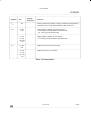
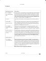
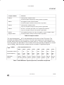
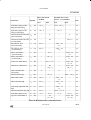
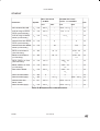
Compare Modes
Function
Mode 0
Interrupt-only compare mode;
several compare interrupts per timer period are possible
Mode 1
Pin toggles on each compare match;
several compare events per timer period are possible
Mode 2
Interrupt-only compare mode;
only one compare interrupt per timer period is generated
Mode 3
Pin set ‘1’ on match; pin reset ‘0’ on compare time overfl ow;
only one compare event per timer period is generated
Double
Register Mode
Two registers operate on one pin; pin toggles on each compare match;
several compare events per timer period are possible.
Table 6 Compare modes
The input frequencies fTx for Tx are determined as a function of the CPU clocks. The
formulas are detailed in the user manual. The timer input frequencies, resolution and
periods which result from the selected pre-scaler option in TxI when using a 20MHz CPU
clock are listed in the table below. The numbers for the timer periods are based on a reload
value of 0000H. Note that some numbers may be rounded to 3 significant fi gures.
fCPU = 20MHz
Timer Input Selection TxI
000B
001B
010B
011B
100B
101B
110B
111B
Pre-scaler for fCPU
8
16
32
64
128
256
512
1024
Input Frequency
2.5
MHz
1.25
MHz
625
kHz
313
kHz
156
kHz
78.1
kHz
39.1
kHz
19.5
kHz
Resolution
400ns
800ns
1.60µs
3.20µs
6.40µs
12.8µs
25.6µs
51.2µs
Period
26.2ms
52.4ms
105ms
210ms
419ms
839ms
1.68s
3.36s
Table 7 CAPCOM timer input frequencies, resolution and periods
42-1701-03
27/78