1
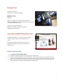
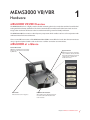
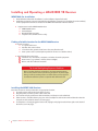
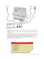
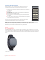
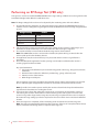
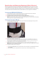
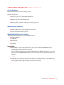
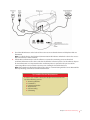
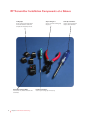
ElmoTech User Guide
TrackerPAL™ User Guide
MEMS3000 & E3 Presence Monitoring
.
ii
Table of Contents
MEMS3000 VB/VBR Hardware
MEMS3000 VB\VBR Overview
MEMS3000 at a Glance
Installing and Operating a MEMS3000 VB Receiver
RF Transmitter
RF Transmitter Installation Components at a Glance
Installing the RF Transmitter (VBR only)
Performing an RF Range Test (VBR only)
MEMS3000 VB Alarms
MEMS3000 VBR Transmitter Alarms
Deactivating and Removing Equipment (End of Service)
MEMS3000 VB/VBR Offender Guidelines
E3 RF Presence MonitoringHardware
E3 Radio Frequency (RF) Overview
Installing and Operating an E3 RF Receiver/Transmitter
RF Transmitter Installation Components at a Glance
Installing the RF Transmitter
Performing an RF Range Test (VBR only)
E3 RF Receiver/Transmitter Common Events
Deactivating and Removing Equipment (End of Service)
E3 RF Offender Guidelines
ElmoTech E3 Software
Logging In
Enrolling a New Offender
Downloading Information to the Receiver
Configuring Offender Schedules
Capturing Enrollment Reference Picture (MEMS3000 Only)
Deactivating Equipment (End of Service)
Exiting the Software
1
1
2
4
5
6
8
9
11
12
13
15
16
18
19
21
22
24
25
27
29
30
31
33
35
35
iii
iv
Contact Us
SecureAlert Corporate
866 451-6141 | M-F 8am-5pm (MST)
Monitoring Center
800 466-1377 | 24/7
Officer ID:
When contacting the SecureAlert Monitoring Center
concerning a MEMS3000 device, please request to speak with
an Alcohol Monitoring Specialist.
SecureAlert Training Department
800 451-6141 Option 4 | M-F 8am-5pm (MST)
[email protected]
www.SecureAlertUniversity.com
SecureAlert Unvierstiy is an online resource for training
materials, resources and job aids, certification and
more.
Our goal is to provide these training materials in a
myriad of methods to meet the diverse needs of our
customer base.
To log on for the first time
1. Visit www.securealertuniversity.com
2. Click the Create Account link in the top right corner of the window.
3. Enter the required information, create a password and click Create Account. Your account will be evaluated for approval within one business day. You will be notified by email when your account is approved.
4. Once your account has been approved, return to www.securealertuniversity.com and enter your email
address and the password you created and click submit to login.
v
vi
MEMS3000 VB/VBR
Hardware
1
MEMS3000 VB\VBR Overview
The MEMS3000 Receiver is a highly sensitive alcohol monitoring device (to .019%) that combines breath alcohol
testing with video identity verification. The device automatically transmits breath alcohol test results and user
images taken at the time of the test to the SecureAlert monitoring center for identify verification.
The MEMS3000 VBR also contains a radio frequency component which enables it to be used in conjunction with
an RF transmitter for home confinement.
There are two different versions of the MEMS3000 VB and VBR to meet offenders’ needs. One that communicates
using a regular telephone landline and one that uses a cellular connection to communicate.
MEMS3000 at a Glance
Camera Mirror Panel
Offenders should face this panel when
taking a test. The mirror is surrounded
by flash leds.
Camera LED
Indicates that a test is in progress.
Operation Panel
Offenders press Start to begin the
test (or initiate a self test) and then
follow the illuminated instructions
on this panel to complete the
breath alcohol test.
Breath Alcohol Test Straw
When taking a test, offenders blow into
the straw to have their breath alcohol
level measured.
Chapter 1 MEMS3000 VB\VBR Hardware
1
Installing and Operating a MEMS3000 VB Receiver
MEMS3000 Pre-installation
1. Enroll offender in ElmoTech E3 software (see the Software chapter for details)
2. Verify that you have the correct equipment for the offender’s program type and that the serial number(s)
on the equipment match those selected on the Offender Details tab in the E3 software
SS
Equipment to install a MEMS3000 Receiver:
SS MEMS3000 Receiver
SS Power Adapter
SS Breath Alcohol Test Straw
SS Telephone line (landline devices only)
Finding a Suitable Location for the MEMS 3000 Receiver
SS
Place the receiver:
SS In a quiet, well lit area
SS On a flat and secure surface
SS 3 feet above the ground and at least 1 foot away from the wall.
SS Near a power source (and telephone jack if the receiver is a landline device)
SS
Avoid placing the receiver near:
Television sets, microwaves, computers and other electrical equipment
Heat sources (e.g., radiators, air ducts, direct sunlight)
Mirrors and other reflective materials
Tip: Avoid Backlighting\Exposure Problems
Once a location has been selected, it’s also important to position
the receiver with the mirror panel facing away from any direct light.
Doing so will ensure that pictures are taken at the correct exposure
and that the offender’s photo is captured with sufficient detail.
Installing the MEMS 3000 Receiver
Once the receiver has been positioned in an appropriate location:
1. Insert the power cord into the back of the receiver.
2. Plug the power cord into a power outlet in the wall.
3. The receiver will play audio tones while it initializes and beep once it has finished.
4. If the receiver is a landline device, plug one end of a telephone cord into the wall and the other into the
Line jack on the back of the device (see next page).
5. If a telephone is already plugged in to the wall, unplug it and plug it into the Phone jack on the back of
the device (see next page).
2
Chapter 1 MEMS3000 VB\VBR Hardware
MEMS3000 Landline Receiver
6. Check the LED indicators on the back of the receiver to ensure that the Power and Telephone LEDs are
illuminated.
Note: For cellular devices, the Telephone LED indicates whether the device has successfully connected to
a cellular network.
7. Once both LEDs are illuminated, use the E3 software or contact the monitoring center to download
enrollment information to the device and take the offender’s reference picture. See the Software chapter
for more information. It is important that the enrollment picture is captured in the presence of the
supervising officer to ensure that the correct person is taking the breath alcohol tests.
Note: If the telephone LED is flashing, the device is communicating with the server. Wait until the LED
stops flashing, to download enrollment information.
Tip: Landline Device Requirements
In order to use a landline device, the telephone line must not have
any of the following services:
SS Answering Machine
SS Fax Machine
SS Fax\Internet Modem
SS ADSL Internet
SS Call Forwarding
SS Call Waiting
Chapter 1 MEMS3000 VB\VBR Hardware
3
Performing a Breath Alcohol Test
Breath alcohol tests can be scheduled in the E3 software or administered
manually by pressing the Press Start button on the front of the receiver.
1. When the device receives the command to administer a test, it produces
an audio siren.
2. Press Start.
3. The device beeps and the Blow and Face the Mirror LEDs illuminate on
the front panel.
4. Blow into the breath alcohol test straw
5. During the test, the camera flash will trigger and a picture will be taken
for video ID
6. The device will beep when the test is completed and the Test Completed
LED will illuminate on the front panel
The picture and results will then appear in the software where they can be
evaluated and compared with (or saved as) a reference picture.
MEMS3000 Receiver Front Panel
Note: Pictures should clearly display the offender’s face without obstruction. Offenders should refrain from
wearing appearance altering clothing while taking breath alcohol tests (e.g., sunglasses, hats).
Offenders may not touch the straw while the test is being administered.
RF Transmitter
The MEMS3000 VBR can be used in conjunction with a transmitter to confine an offender to an area near the
receiver. The transmitter sends Radio Frequency (RF) signals to the MEMS3000 receiver every 20 seconds. If the
receiver doesn’t receive the signal it will generate an event message in the software and alert the monitoring
center.
E3 RF Transmitter
4
Chapter 1 MEMS3000 VB\VBR Hardware
RF Transmitter Installation Components at a Glance
Locking Clips
Used to lock the transmitter straps
around the offender’s ankle and
complete the anti-tamper circuit.
Manual Reset Device (MRD)
Used to turn on, calibrate and turn off a
transmitter.
Strap Locking Tool
Used to secure the locking clips
into place.
Snake Eye Screwdriver
Used to remove and attach
straps to the transmitter.
Flat Head Screwdriver
Used to open locking clips if necessary.
Chapter 1 MEMS3000 VB\VBR Hardware
5
Installing the RF Transmitter (VBR only)
RF Transmitter Pre-installation
1. Enroll offender in ElmoTech E3 software (see the software chapter for details).
2. Verify that you have the correct equipment for the offender’s program type and that the serial number(s)
on the equipment match those selected on the Offender Details tab in the E3 software.
3. Install the MEMS3000 VBR receiver.
SS
Equipment to install an RF Transmitter:
SS Transmitter
SS Strap Holder
SS Locking Clips
SS Manual Reset Device (MRD)
SS Strap Locking Tool
SS Flat Head Screwdriver (to remove clips if necessary)
SS Snake Eye Screwdriver (to replace straps if necessary)
Activating (turning on) the RF Transmitter
Before the Transmitter can be attached to the Offender, you must first activate and calibrate the transmitter.
1. Press the contact points on the top of the MRD to the metal pins on the strap with the ON button closest
to the transmitter.
2. Press the ON button
3. Hold the MRD in position as the red LED illuminates for 2 seconds and then blinks for two seconds.
Note: If the command failed, the the MRD LED will shut off without blinking. If the MRD battery is low, the
LED will blink as soon as the button is pressed.
4. Set the transmitter on its side while the transmitter powers on and begins communicating with the
receiver.
5. The MEMS30000 Receiver should emit a beeping sound within 60 seconds indicating that communication has been established
Note: The beeping will continue each time the receiver receives a signal from the transmitter until the
transmitter is secured around an offender’s ankle, or until the devices downloads the program information from the E3 software.
6. Leave the transmitter laying on its side until you are ready to install it. Once the transmitter is moved, you
have two minutes to attach it to the offender’s ankle.
7. If you do not install the transmitter successfully within two minutes. Turn the transmitter off (see page
12), wait 15 seconds, then repeat the activation/installation process.
6
Chapter 1 MEMS3000 VB\VBR Hardware
Attaching the Transmitter
1. Place a strap holder over the short strap (pin side) of the Transmitter.
Strap Holder
2. Attach the female Clip to the underside of the Transmitter’s short strap (to lie against the Offenders skin).
3. Wrap the Transmitter around the narrowest point of the offender’s ankle.
4. Lay the long strap over the other strap, ensuring that the pins are protruding through both straps.
5. Push the other side (male) of the locking clip into place, securing the strap into position around the
offender’s ankle
6. Slide the strap holder over the end of the long strap to hold it in place.
Tip: Fitting the Transmitter
The Transmitter must fit tightly around the offender’s ankle, but
not squeezing. It is also permissible for an offender to wear a sock
underneath the ankle Transmitter. Try to mount the Transmitter
over the sock before it is fastened. Keep in mind that if the strap is
too loose, the transmitter may report false strap tamper alarms.
7. Finally, clamp the two clips together using the Strap Locking Tool. The clips will click together indicating
that the clips are fastened properly
8. If you haven’t done so already, use the E3 software or contact the monitoring center to download
enrollment information to the device and take the offender’s reference picture. Also, ask the monitoring
center to confirm that the transmitter was successfully calibrated before moving on.
Chapter 1 MEMS3000 VB\VBR Hardware
7
Performing an RF Range Test (VBR only)
A range test is used to ensure that the MEMS3000 Receiver’s range setting is sufficient to receive signals from the
transmitter throughout the offender’s confinement area.
Note: The Range setting for the receiver can be adjusted by the monitoring center in the E3 software.
1. Use the table below to determine an appropriate initial range setting for the MEMS3000 Receiver (e.g.
medium). Select a setting that is big enough to include the offender’s home but not big enough for them
to leave.
Range Setting
Radius
Short
15-45ft
Medium
45-80ft
Long
80-145ft
Maximum
145-260ft
2. Call the monitoring center and request that the range settings for the receiver be adjusted (per your
estimation) and request that they send a command to the device to begin a range test.
3. The receiver will beep 3 times to indicate thath the range test has been initiated.
Note: If the MEMS3000 receiver is connected to a landline, the phone will ring 2-3 times before the
reciever picks up the call and initiates the test.
4. Throughout the test, the receiver will beep every 20 seconds when it receives a signal from the
transmitter
5. Escort the offender throughout the location, pausing occaisionally to confirm that the receiver is
receiving signal from the transmitter.
Pay special attention to:
SS Places where the offender may be located for long periods of time (e.g., living room, bedroom,
bathroom)
SS Remote locations where the offender is permitted (e.g., garage, cellar back yard)
SS Extreme corners of the location
SS Behind large metal objects
In these locations, pause long enough for the transmitter to beep 4 times (two minutes) to ensure that
there is sufficient signal strength for the transmiter to consistenly communicate with the receiver
Note: If possible, have another person stand by the receiver to listen for the beeps that indicate that
signals from the transmitter are reaching the receiver.
6. If you do not hear a beep after waiting for one minute in a test location, the transmitters signals are
not reaching the receiver in that location. Call the monitoring center and request an increase in the
receiver’s range and to begin another range test once the range is updated. If the receiver is already at
the maximum range setting, try to find a new place for the receiver that is more central to the offender’s
location
7. Once the range test is completed, call the monitoring center and ask them to end the range test.
Note: The range test automatically terminates after 15 minutes. If the test isn’t completed when the test
expires, contact the monitoring center to request another range test.
8
Chapter 1 MEMS3000 VB\VBR Hardware
MEMS3000 VB Alarms
The MEMS3000 Receiver initiates a routine sanity call to the monitoring center in order to report the status of the
equipment and upload all stored events (i.e., events that did not require immediate attention). The table below
details some of the most common event messages that display in the software.
Message
Description
BAT Failed
The Breath Alcohol test has failed (exceeded allowed alcohol limit)
BAT Failed –
Last Retry
The Breath Alcohol test has failed (exceeded number of allowed retries)
Case opened
The receiver’s case has been opened. This is a violation and requires attention.
Case is still open
The receiver’s case is still open. This is cause for concern and requires immediate
attention.
Power too high
The receiver has indicated that the electrical current that is being received from the
external power supply is too high. This is a cause for concern and requires attention.
BAT Request
Failed
The BAT request has failed.
Buffer Full
The MEMS 3000 HomeStation memory is full. Cannot store any additional pictures. Send
a download command to the receiver.
Low battery
The receiver’s internal backup battery is low on power. This is a cause for concern and
requires immediate attention.
Phone line
failure
The phone line that connects the receiver to incoming / outgoing calls has failed, or has
been disconnected. This is a violation and should be reported.
Phone line
restored
The phone line that connects the receiver to incoming / outgoing calls has been reconnected after having been defined as failed or disconnected.
Power failure
The power cable that connects the receiver to the external power supply has failed, or
has been disconnected.
Power restored
The power cable that connects the receiver to the external power supply has been
replaced or reconnected after having been defined as failed or disconnected.
End of Service
The receiver has been deactivated and servce has halted
Receiver Missed Call The system has indicated that the receiver did not perform its pre-defined status call-in
(sanity call) procedure.
Alcohol Sensor
Failure
The alcohol sensor has failed during the test. Because the picture mechanism works
according to the alcohol sensor, this could mean that no picture was taken or this could
be due to sensor warm up period. If detected unit will prompt for another test immediately
Alcohol Test
activated
The alcohol test has been activated.
Alcohol Test
Cancelled
The Breath Alcohol test has been cancelled
Alcohol Test
Suspended
The alcohol test was suspended.
BAT failed –
request time out
The breath alcohol test request has been defined as failed. This is activated when the
number of test request attempts has exceeded the defined time out parameter.
Chapter 1 MEMS3000 VB\VBR Hardware
9
10
Message
Description
BAT Succeeded
The breath alcohol test has succeeded (alcohol level did not exceed allowed limit)
Case closed
The receiver’s case has been closed after it was initially opened.
Case Tilt
The receiver is not positioned on its original flat (parallel) surface. This could suggest
that the receiver has been moved. This is a cause for concern and may require attention.
Download
Successful
All events have been successfully downloaded from the receiver.
Init Enrolment
failed
The enrolment request failed.
Init Enrolment
Successful
The enrolment request was initiated successfully.
Line / phone
connected
correctly
The line or phone lines that connect the receiver to all incoming and outgoing calls has
been reconnected correctly, after having initially been defined as connected incorrectly.
Line / phone
connected
incorrectly,
requires switch
The line / phone cables that connect the receiver to incoming / outgoing calls has been
connected incorrectly. The cables will have to be disconnected and then reconnected
correctly.
New version
installed
The receiver has indicated that a new software version has been installed successfully.
Offender start
monitoring
The monitored individual’s monitoring program has started.
Offender stop
monitoring
The monitored individual’s monitoring program has been stopped.
Phone was used
The phone line that is connected to the receiver was in use. This means that any
download or upload of information, during this period, cannot be performed.
Picture Capture
Succeeded
The picture capture procedure has succeeded.
Receiver is still
in tilt
The receiver has indicated that it is still in a tilted (non parallel) position.
Chapter 1 MEMS3000 VB\VBR Hardware
MEMS3000 VBR Transmitter Alarms
The table below details some of the event messages that are specific to the RF component of the MEMS3000
VBR. See the previous table for MEMS3000 related events.
Message
Description
Body tamper
The monitored individual’s transmitter has possibly been removed or installed to
loose on the individual’s ankle. Re-install to a tighter fit.
Body tamper
reset
The transmitter body tamper sensor has been reset (re-attached to the ankle) after
the tag was initially removed from the monitored individual’s ankle.
Strap tamper
The monitored individual’s transmitter has been opened or cut. and should be
reported. Check to ensure there are no cuts/nicks/re-calibrate and or replace straps
Strap tamper
reset
The transmitter’s strap has been closed, after initially being opened or cut.
Left during
curfew
The monitored individual has left the curfew location during a curfew schedule.
Verify Schedule is correct.
Returned after
absence
The monitored individual has returned the curfew location, after being defined as
absent. Verify Schedule is correct.
Did not return
The monitored individual has not returned in time for the defined curfew frame.
Transmitter Tamper
The transmitter has indicated both Strap tamper and Body Tamper have occurred
at the same time. This is a cause for concern and requires immediate attention.
Responding to Strap Tamper Events
If the monitoring center detects a Strap Tamper event for the Offender’s Transmitter, the Transmitter must be
reset (turned off and back on) using the MRD.
Tamper events can be caused by the following issues:
SS The offender tried to cut, open, or otherwise tamper with the transmitter
SS The transmitter straps are defective
Check the transmitter for any signs of tampering, such as:
SS Cracks on the clip
SS Broken pins
SS Tearing in the straps
SS Cracks on the transmitter body
If it is determined that the straps are defective, they can be replaced using the snake eye screwdriver included in
your tool kit.
Chapter 1 MEMS3000 VB\VBR Hardware
11
Deactivating and Removing Equipment (End of Service)
Before any equipment is removed from the offender’s location, the MEMS3000 receiver should receive an End
of Service (EOS) command. This will happen automatically on the offender’s program end date as recorded on
the Details tab (see the softare chapter). A manual EOS can also be sent from the E3 software by the monitoring
center. The device must recive the End of Service command before it can be reassigned to a new offender.
Disconnecting a MEMS3000 VB\VBR Receiver
1.
2.
3.
4.
Call the monitoring center to confirm that the device has received the End of Service command.
Unplug the power cord from the wall and the back of the receiver.
Unplug the telephone cord from the back of the receiver (landline only).
Pack the device and cables into the carrying case including the Breath Alcohol Test Straw.
Note: The straw can be discarded once you’ve returned to your agency. It is best not to discard any equipment until you have departed the offender’s location.
Removing the Transmitter (VBR only)
1. Insert a the tip of a flathead screwdriver into the grooves of the clip and gently pry the clip open. Take
care not to damage or cut the strap.
2. Collect all the fragments of the broken clip.
3. Deactivate (turn off ) the transmitter by pressing the contact points on the MRD to the metal pins on
the strap and pressing the OFF button. Make sure that the MRD is positioned so that the OFF button is
closest to the free end of the strap (away from the transmitter).
4. Hold the MRD in position as the red LED illuminates for 2 seconds and then blinks for two seconds.
Note: If the command failed, the the MRD LED will shut off without blinking. If the MRD battery is low, the
LED will blink as soon as the button is pressed.
5. Pack the transmitter into the carrying case.
SS
SS
12
If desired, the MEMS3000 Receiver and Transmitter can be cleaned after use by wiping with an alcohol
based solution.
One or both straps can be replaced if there is excessive wear or visible damage to the strap.
Chapter 1 MEMS3000 VB\VBR Hardware
MEMS3000 VB/VBR Offender Guidelines
General Guidelines
Be sure to inform offenders of the following guidelines
Offenders should never:
SS Touch or move the MEMS3000 Receiver once it has been installed
SS Place any objects on top of the MEMS3000 Receiver
SS Disconnect the power cord from the MEMS3000 Receiver
SS Attempt to open the MEMS3000 Receiver
SS Adjust or tamper with the breath alcohol rest straw
SS Obstruct their faces or identiy while taking a breath alcohol test
SS Wear inappropriate/insufficient clothing while taking a breath alcohol test
MEMS3000 VBR Guideliness
Offenders should never:
SS Exit the confinement area without obtaining permission
SS Attempt to open the Transmitter strap
SS Cut or break the Transmitter strap or clip
MEMS3000 VB/VBR Landline Guideines
The telephone line must not have any of the following services:
SS Answering Machine
SS Fax Machine
SS Fax\Internet Modem
SS ADSL Internet
SS Call Forwarding
SS Call Waiting
Inbound Calls
SS
SS
When offenders receive a call, the phone rings up to six times before the MEMS3000 Receiver
automatically answers and disconnects the call
While using the phone, the receiver may emit short audio tones indicating that the MEMS3000 Receiver
needs to call the monitoring center computer. When this occurs, offenders should hang up as soon as
possible to enable the MEMS3000 Receiver to make its call. Failure to give up the line could result in a
violation.
Outbound Calls
SS
If offenders try to perform an outbound call and hears sharp modem/fax sounds, they should immediately hang up the phone. This indicates that the MEMS3000 Receiver needs to call the monitoring
center computer. Failure to give up the line will result in a violation.
Chapter 1 MEMS3000 VB\VBR Hardware
13
14
Chapter 1 MEMS3000 VB\VBR Hardware
E3 RF Presence Monitoring
Hardware
2
E3 Radio Frequency (RF) Overview
The E3 RF Presence Monitoring system consists of the RF Transmitter worn on the offenders’ ankle and the E3 RF
Receiver which is placed in the offender’s home and monitors the offender’s presence (or absence). Using the E3
software, users can upload an offender’s schedule to the receiver, designating when the offender must be in and
if there are times the offender may (or must) be out of his/her confinment area. The receiver will then report any
violations to the monitoring center.
Both the transmitter and receiver are also equipped with tamper sensors and will report any detected violations
to the monitoring center.
The E3 RF Cellular Receiver Telephone
The E3 RF Cellular Receiver is also equiped with a telephone receiver that can be used to communicate with the
SecureAlert monitoring center and emergency services.
Call Button
Press this button to contact
the SecureAlert monitoring
center. This button also
answers incoming calls.
End Call Button
Press this button to end a call.
Emergency button
Press this button to dial 911
for emergency purposes.
RF Transmitter
Worn on the offender’s ankle
and sends RF signals to the
reciever.
Chapter 2 E3 RF Presence Monitoring
15
Installing and Operating an E3 RF Receiver/Transmitter
E3 RF Pre-installation
1. Enroll offender in ElmoTech E3 software (see the software chapter for details)
2. Verify that you have the correct equipment for the offender’s program type and that the serial number(s)
on the equipment match those selected on the Offender Details tab in the E3 software
SS
Equipment to install an E3 RF Receiver / Transmitter:
SS E3 Receiver
SS Power Adapter
SS Telephone line (only applicible for landline devices)
SS Transmitter
SS Strap Holder
SS Locking Clips
SS Manual Reset Device (MRD)
SS Strap Locking Tool
SS Flat Head Screwdriver (to remove clips if necessary)
SS Snake Eye Screwdriver (to replace straps if necessary)
Finding a Suitable Location for the E3 RF Receiver
SS
Place the receiver:
SS In a central location of the offender’s home
SS On a flat and secure surface
SS 3 feet above the ground and at least 1 foot away from the wall.
SS Near a power source (and telephone jack if the receiver is a landline device)
SS
Avoid placing the receiver near:
Television sets, microwaves, computers and other electrical equipment
Heat sources (e.g., radiators, air ducts, direct sunlight)
Sinks
Installing the E3 RF Receiver
Once the receiver has been positioned in an appropriate location:
1. Insert the power cord into the back of the device
2. Plug the power cord into a power outlet in the wall
3. The receiver will play audio tones while it initializes and beep once it has finished
4. If the receiver is a cellular device, check the LEDs on the back to ensure that the left and right LEDs are
illuminated
5. If the receiver is a landline device, plug one end of a telephone cord into the wall and the other into the
Line jack on the back of the device (see next page).
6. If a telephone is already plugged in to the wall, unplug it and plug it into the Phone jack on the back of
the device (see next page).
16
Chapter 2 E3 RF Presence Monitoring
E3 Landline Receiver
7. Check the LED Indicators on the back of the receiver to ensure that the Power and Telephone LEDs are
illuminated.
Note: For cellular devices, the Telephone\Communication LED indicates whether the device has successfully connected to a cellular network.
8. If both LEDs are illuminated, use the E3 software or contact the monitoring center to download
enrollment information to the device and take the offender’s reference picture. See the software chapter
for more information. It is important that the enrollment picture is captured in the presence of the
supervising officer to ensure that the correct person is taking the breath alcohol tests.
Note: If the telephone\cellular LED is flashing, the device is communicating with the server. Wait until the
LED stops flashing, to download enrollment information.
Tip: Landline Device Requirements
In order to use a landline device, the telephone line must not have
any of the following services:
SS Answering Machine
SS Fax Machine
SS Fax\Internet Modem
SS ADSL Internet
SS Call Forwarding
SS Call Waiting
Chapter 2 E3 RF Presence Monitoring
17
RF Transmitter Installation Components at a Glance
Locking Clips
Used to lock the transmitter straps
around the offender’s ankle and
complete the anti-tamper circuit.
Manual Reset Device (MRD)
Used to turn on, calibrate and turn off a
transmitter.
18
Chapter 2 E3 RF Presence Monitoring
Strap Locking Tool
Used to secure the locking clips
into place.
Flat Head Screwdriver
Used to open locking clips if necessary.
Snake Eye Screwdriver
Used to remove and attach
straps to the transmitter.
Installing the RF Transmitter
RF Transmitter Pre-installation
1. Enroll offender in ElmoTech E3 software (see software chapter for details)
2. Verify that you have the correct equipment for the offender’s program type and that the serial number(s)
on the equipment match those selected on the Offender Details tab in the E3 software
3. Install the E3 RF Receiver
SS
Equipment to install the Transmitter:
SS Transmitter
SS Strap Holder
SS Locking Clips
SS Manual Reset Device (MRD)
SS Strap Locking Tool
SS Flat Head Screwdriver (to remove clips if necessary)
SS Snake Eye Screwdriver (to replace straps if necessary)
Activating (turning on) the RF Transmitter
Before the Transmitter can be attached to the Offender, you must first activate and calibrate the transmitter.
1. Press the contact points on the top of the MRD to the metal pins on the strap with the ON button closest
to the transmitter.
2. Press the ON button
3. Hold the MRD in position as the red LED illuminates for 2 seconds and then blinks for two seconds.
Note: If the command failed, the the MRD LED will shut off without blinking. If the MRD battery is low, the
LED will blink as soon as the button is pressed.
4. Set the transmitter on its side while the transmitter powers on and begins communicating with the
receiver.
5. The E3 Receiver should emit a beeping sound within 60 seconds indicating that communication has
been established
Note: The beeping will continue each time the receiver receives a signal from the transmitter until
the transmitter is secured around an offender’s ankle, or until the devices downloads the program
information from the E3 software.
6. Leave the transmitter laying on its side until you are ready to install it. Once the transmitter is moved, you
have two minutes to attach it to the offender’s ankle.
7. If you do not install the transmitter successfully within two minutes. Turn the transmitter off (see page
12), wait 15 seconds, then repeat the activation/installation process.
Chapter 2 E3 RF Presence Monitoring
19
Attaching the Transmitter
1. Place a strap holder over the short strap (pin side) of the Transmitter.
Strap Holder
2. Attach the female Clip to the underside of the Transmitter’s short strap (to lie against the Offenders skin).
3. Wrap the Transmitter around the narrowest point of the offender’s ankle.
4. Lay the long strap over the other strap, ensuring that the pins are protruding through both straps.
5. Push the other side (male) of the locking clip into place, securing the strap into position around the
offender’s ankle
6. Slide the strap holder over the end of the long strap to hold it in place.
Tip: Fitting the Transmitter
The Transmitter must fit tightly around the offender’s ankle, but
not squeezing. It is also permissible for an offender to wear a sock
underneath the ankle Transmitter. Try to mount the Transmitter
over the sock before it is fastened. Keep in mind that if the strap is
too loose, the transmitter may report false strap tamper alarms.
7. Finally, clamp the two clips together using the Strap Locking Tool. The clips will click together indicating
that the clips are fastened properly.
8. If you haven’t done so already, use the E3 software or contact the monitoring center to download
enrollment information and schedule to the device. See the Software for more information.
20
Chapter 2 E3 RF Presence Monitoring
Performing an RF Range Test (VBR only)
A range test is used to ensure that the receiver’s range setting is sufficient to receive signals from the transmitter
throughout the offender’s confinement area.
Note: The Range setting for the receiver can be adjusted by the monitoring center in the E3 software.
1. Use the table below to determine an appropriate initial range setting for the E3 Receiver (e.g. medium).
Select a setting that is big enough to include the offender’s home but not big enough for them to leave.
Range Setting
Radius
Short
15-45ft
Medium
45-80ft
Long
80-145ft
Maximum
145-260ft
2. Call the monitoring center and request that the range settings for the receiver be adjusted (per your
estimation) and request that they send a command to the device to begin a range test.
3. The receiver will beep 3 times to indicate thath the range test has been initiated.
Note: If the receiver is connected to a landline, the phone will ring 2-3 times before the reciever picks up
the call and initiates the test.
4. Throughout the test, the receiver will beep every 20 seconds when it receives a signal from the
transmitter.
5. Escort the offender throughout the location, pausing occaisionally to confirm that the receiver is
receiving signal from the transmitter.
Pay special attention to:
SS Places where the offender may be located for long periods of time (e.g., living room, bedroom,
bathroom)
SS Remote locations where the offender is permitted (e.g., garage, cellar back yard)
SS Extreme corners of the location
SS Behind large metal objects
In these locations, pause long enough for the transmitter to beep 4 times (two minutes) to ensure that
there is sufficient signal strength for the transmiter to consistenly communicate with the receiver.
Note: If possible, have another person stand by the receiver to listen for the beeps that indicate that
signals from the transmitter are reaching the receiver.
6. If you do not hear a beep after waiting for one minute in a test location, the transmitters signals are
not reaching the receiver in that location. Call the monitoring center and request an increase in the
receiver’s range and to begin another range test once the range is updated. If the receiver is already at
the maximum range setting, try to find a new place for the receiver that is more central to the offender’s
location.
7. Once the range test is completed, call the monitoring center and ask them to end the range test.
Note: The range test automatically terminates after 15 minutes. If the test isn’t completed when the test
expires, contact the monitoring center to request another range test.
Chapter 2 E3 RF Presence Monitoring
21
E3 RF Receiver/Transmitter Common Events
The E3 Receiver initiates a routine sanity call to the monitoring center in order to report the status of the
equipment and upload all stored events (i.e., events that did not require immediate attention). The table below
details some of the most common event messages that display in the software.
22
Message
Description
Body tamper
The monitored individual’s transmitter has possibly been removed or installed to
loose on the individual’s ankle. Re-install to a tighter fit.
Body tamper
reset
The transmitter body tamper sensor has been reset (re-attached to the ankle) after
the transmitter was initially removed from the monitored individual’s ankle.
Case opened
The receiver’s case has been opened.
Case closed
The receiver’s case has been closed after it was initially opened.
Case Tilt
The receiver is not positioned on its original flat (parallel) surface. This could
suggest that the receiver has been moved. This is a cause for concern and may
require attention.
Receiver not in
tilt
The receiver has indicated that it has been returned to its non-tilted (parallel) position, after initially being in a tilted (non parallel) position.
Strap tamper
The monitored individual’s transmitter has been opened or cut. Check to ensure
there are no cuts/nicks/re-calibrate and or replace straps
Strap tamper
reset
The transmitter’s strap has been closed, after initially being opened or cut.
Phone line
failure
The phone line that connects the receiver to incoming/outgoing calls has failed, or
has been disconnected.
Event buffer full
The receiver’s event memory buffer is full. The receiver is unable to store any more
event information and requires immediate attention. Send a download command
to the receiver.
GSM connection
failed
The receiver has indicated that it is unable to connect to the cellular network
(applicable to cellular receivers only). This could be a cause for concern and may
require attention.
GSM connection
restored
The receiver has indicated that it is now able to connect to the cellular network
(applicable to cellular receivers only), after initially being unable to perform a
connection. This could be a cause for concern and may require attention.
Receiver Low battery
The receiver’s internal backup battery is low on power. This is a cause for concern
and requires immediate attention.
Left during
curfew
The monitored individual has left the curfew location during a curfew schedule.
Verify Schedule is correct.
Returned after
absence
The monitored individual has returned the curfew location, after being defined as
absent.
Did not return
The monitored individual has not returned in time for the defined curfew frame.
Receiver Miss Call
The monitored individual receiver did not check in with the server as schedule, this
is a cause for concern as there is currently not communication with the equipment.
Power failure
The power cable that connects the receiver to the external power supply has failed,
or has been disconnected.
Power restored
The power cable that connects the receiver to the external power supply has been
replaced or reconnected after having been defined as failed or disconnected.
Chapter 2 E3 RF Presence Monitoring
Message
Description
Download
offender failed/request
time out
The receiver unit has indicated that it has failed to receive the information the
downloaded offender’s details. This could be caused due to phone features on the
line. All features should be removed.
Phone line
restored.
The phone line that connects the receiver to incoming/outgoing calls has been
reconnected after having been defined as failed or disconnected.
No cell net
coverage
The receiver’s cellular network coverage is currently unavailable. This is a cause for
concern and requires attention.
Cell net coverage
restored.
The receiver’s cellular network coverage has been restored after it was reported to
be unavailable. This could be a cause for concern and may require attention.
Transmitter Tamper
The transmitter has indicated both Strap tamper and Body Tamper have occurred
at the same time. This is a cause for concern and requires immediate attention.
Responding to Strap Tamper Events
If the monitoring center detects a Strap Tamper event for the Offender’s Transmitter, the Transmitter must be
reset (turned off and back on) using the MRD.
Tamper events can be caused by the following issues:
SS The offender tried to cut, open, or otherwise tamper with the transmitter
SS The transmitter straps are defective
Check the transmitter for any signs of tampering, such as:
SS Cracks on the clip
SS Broken pins
SS Tearing in the straps
SS Cracks on the transmitter body
If it is determined that the straps are defective, they can be replaced using the snake eye screwdriver included in
your tool kit.
Chapter 2 E3 RF Presence Monitoring
23
Deactivating and Removing Equipment (End of Service)
Before any equipment is removed from the offender’s location, the E3 receiver should receive an End of Service
(EOS) command. This will happen automatically on the offender’s program end date as recorded on the Details
tab (see the softare chapter). A manual EOS can also be sent by the monitoring center from the E3 software. The
device must recive the End of Service command before it can be reassigned to a new offender.
Disconnecting an E3 Receiver
1.
2.
3.
4.
Call the monitoring center to confirm that the device has received the End of Service command.
Unplug the power cord from the wall and the back of the receiver.
Unplug the telephone cord from the back of the receiver (landline only).
Pack the device and cables into the carrying case
Removing the Transmitter
1. Insert a the tip of a flathead screwdriver into the grooves of the clip and gently pry the clip open. Take
care not to damage or cut the strap.
2. Collect all the fragments of the broken clip. Do not leave broken clips or other equipment at the
offender’s home.
3. Deactivate (turn off ) the transmitter by pressing the contact points on the MRD to the metal pins on
the strap and pressing the OFF button. Make sure that the MRD is positioned so that the OFF button is
closest to the free end of the strap (away from the transmitter).
4. Hold the MRD in position as the red LED illuminates for 2 seconds and then blinks for two seconds.
Note: If the command failed, the the MRD LED will shut off without blinking. If the MRD battery is low, the
LED will blink as soon as the button is pressed.
5. Pack the transmitter into the carrying case
SS
SS
24
If desired, the E3 Receiver and Transmitter can be cleaned after use by wiping with an alcohol based
solution.
One or both straps can be replaced if there is excessive wear or visible damage to the strap.
Chapter 2 E3 RF Presence Monitoring
E3 RF Offender Guidelines
General Guidelines
Be sure to inform offenders of the following guidelines
Offenders should never:
SS Touch or move the E3 Receiver Unit once it has been installed
SS Place any objects on top of the E3 Receiver Unit
SS Disconnect the power cord from the E3 Receiver Unit
SS Attempt to open the E3 Receiver Unit
SS Exit the confinement area without obtaining permission
SS Attempt to open the Transmitter strap
SS Cut or break the Transmitter strap or clip
E3 RF Landline Guideines
The telephone line must not have any of the following services:
SS Answering Machine
SS Fax Machine
SS Fax\Internet Modem
SS ADSL Internet
SS Call Forwarding
SS Call Waiting
Inbound Calls
SS
SS
When offenders receive a call, the phone rings up to six times before the E3 Receiver automatically
answers and disconnects the call
While using the phone, the receiver may emit short audio tones indicating that the E3 Receiver needs
to call the monitoring center computer. When this occurs, offenders should hang up as soon as possible
to enable the E3 Receiver to make its call. Failure to give up the line could result in a violation.
Outbound Calls
SS
If offenders try to perform an outbound call and hears sharp modem/fax sounds, they should
immediately hang up the phone. This indicates that the E3 Receiver needs to call the monitoring center
computer. Failure to give up the line will result in a violation.
Chapter 2 E3 RF Presence Monitoring
25
26
Chapter 2 E3 RF Presence Monitoring
3
ElmoTech E3 Software
The ElmoTech E3 software is used to enroll offenders and manage their profiles, assign and activate equipment,
administer breath alcohol tests, and create an offender’s confinement schedules for breath alcohol tests and
radio frequency devices.
Logging In
Logging into the softare is a two step process:
1. Logging into the server by establishing a windows Remote Desktop Connection
2. Logging into the E3 ElmoTech software using the login provided to you by the monitoring
center
Update Remote Desktop (first time only)
Before logging in for the first time, you need to ensure that you have the most up to date version of
Remote Desktop.
1. Visit http://support.microsoft.com/kb/969084
2. Select the appropriate update for your version of windows.
Select the appropriate update
Launch Remote Desktop (Option 1)
1. Click Start.
2. Select All Programs > Accessories > Communications > Remote Desktop Connection
Select Remote Desktop Connection
Chapter 3 Software
27
Launch Remote Desktop (Option 2)
1.
2.
3.
4.
Click Start.
Select Run.
Type mstsc in the available field.
Click OK.
Connect to the Remote Desktop Server
1. Type elmotech.securealert.com
2. Click Connect.
3. Once you’ve connected to the server, login using the following username and password:
SS Username: elmotech\vendor
SS Password: SaVe001!
Enter the login information and click the arrow
28
Chapter 3 Software
Log In to the ElmoTech E3 Software
Upon logging in to the remote desktop server, the system automatically launches the ElmoTech E3 software
login screen.
Enter your username and password to login.
Enrolling a New Offender
1. Click the List drop-down button
2. Click Add
3. Complete all required fields (see the table below)
Fields
Description
OID
Offender Identification Number. Enter a number used to identify the offender (e.g., the
offender’s case number). Must be unique to each offender.
First/Last Name Enter the offender’s name.
Officer
Select the supervision officer from the drop-down menu.
Address Fields
Enter the offender’s address. Note that you must select the State, before you can
select the correct city.
Phone Number
If the device uses a landline, the home number is the number used to communicate
with the device and must be entered before selecting the Program Type.
If the device is celluar, select the Program Type first. Then, enter the correct contact
phone number for the offender.
Program Start/
End dates
Defaults to a 4 month period that begins with today’s date. The device automatically
performs an End of Service on the Program End date.
Program Type
Select the type of device that will be assigned to the offender (e.g., MEMS3000 VB).
Equipment
Fields
Click the
button to select the device(s) that will be assigned to the offender.
Devices are identified by unique serial numbers.
Required fields and their definitions. All other fields are preselected or not required.
Chapter 3 Software
29
4. Click Save.
Once all required fields are completed, click Save.
Downloading Information to the Receiver
Clicking the Save button only saves changes in the E3 software. To activate and send program information to the
receiver, send a download command to the device.
1. The software indicates when a receiver has not been activated by displaying the enrollment information
in red. Once a device has been activated, the text turns black.
2. To activate the device, click the Download drop-down at the top of the screen and select Download Now.
Note: The receiver should be installed at the offender’s home before it is activated. To do this from the
offender’s location, install the receiver, then call the SecureAlert monitoring center and request that they
send a download command to the receiver.
3. The offender’s phone will ring when the software communicates to the receiver and the receiver will
automatically answer after 6 rings (landline only).
4. To refresh what is being displayed in the software, click the Get Data button.
30
Chapter 3 Software
Configuring Offender Schedules
The Schedules tab in the E3 software is used to establish when breath alcohol tests will be administered and any
exceptions to offenders’ home confinement (for RF devices).
The Schedule tab. The top half is the RF schedule, the bottom half is the breath alcohol test schedule.
Enter the Offender’s RF Schedule (E3 RF and MEMS3000 VBR Only)
The default RF schedule is an always on confinement zone which means that the offender’s transmitter must
be within range of the recevier all day, every day. Exceptions to the schedule can be entered in the From and To
fields for each day of the week for the duration of the offender’s program (indicated on the Details tab).
The RF section of the Schedule tab.
SS
SS
SS
SS
The schedule pictured above allows the offender to leave from 8 AM to 5 PM Monday through friday
for work and Tuesdays, Thursdays and Sundays for Alcoholics Anonymous meetings.
From and To entries must be in 4 digit/24 hour format (e.g., 08:00).
The checkboxes next to the schedules indicate that the offender must be out during the specified time.
Leaving the boxes unchecked indicates that the offender may be out (not required).
Remember to save all schedule changes and send a download command to the receiver once the
schedule is completed.
Note: The RF schedule is unique for each calendar day. Creating a schedule for one day of the week does not
automatically cause the schedule to recur (e.g., creating a schedule for a specific Monday does not adjust the
schedule for all Mondays.)
Chapter 3 Software
31
Offender RF Schedule Controls at a Glance
Jump to Beginning
Jumps to the first week of the offender’s
schedule
Delete Schedule
Erases all entries on the offender’s schedule,
including those for previous weeks
Previous Week
Goes back one week
Move Entry Up
Shifts the currently selected From and To
entry to the row above
Next Week
Goes forward one
week
Move Entry Down
Shifts the currently selected From and To
entry to the row below
Jump to end
Jumps to the final week of the offender’s
program
Fill Schedule with Current Schedule
Copies the currently viewed week to all of
the offender’s weeks, useful for recurring
appointments (e.g., work)
Jump to specific week
Opens a dialog box which allows users to
jump to a specific week by entering a week
number or date
Delete Row
Deleted the selected row from the schedule
Schedule Change Reason
Allows users to enter a reason for the schedule
change
Add a Row
Adds a row to the the schedule
Enter the Offender’s Breath Alcohol Test Schedule (MEMS3000 Only)
The breath alcohol test section of the Schedule tab allows users to enter how many tests will be administered
to an offender per day and how they will be distributed throughout the day. This portion of the Schedule tab is
different than the RF section in that it is a recurring weekly schedule and is not tied to specific dates.
The MEMS3000 section of the Schedule tab.
SS
SS
SS
SS
SS
Enter From and To times to designate when tests will be administered.
The third column (#) indicates how many tests will be administered during the specified interval, with a
maximum of 9.
Tests are randomized within each time interval.
It is a good practice to create several small intervals spaced evenly throughout the day rather than one
long interval. This facilitates even coverage throughout the day.
Note: In the event that an offender fails a breath alcohol test, the software will automatically send
3 additional tests every 10 minutes in order to measure the rate that the alcohol burns off. This is to
prevent/reduce false positives
(e.g., mouthwash).
Tip: Copy and Paste
Note: Because it could take 30 minutes to
You can copy and paste an offender's schedule from one
complete all 4 tests, you can only schedule
day to the next.
1 test for every 30 minutes (e.g., you can only
1. Hold the Control (Ctrl) key on the keyboard and
schedule 4 tests in a 2 hour window).
click the blue bar at the top of the day that you
Remember to save all schedule changes and
would like to copy.
send a download command to the receiver
2. The copied day turns gray.
once it is installed in the offender's home.
3. Hold the Shift key on the keyboard and click
another day to paste the copied schedule.
32
Chapter 3 Software
Capturing Enrollment Reference Picture (MEMS3000 Only)
Once the MEMS3000 reciver is installed and activated, the offender must complete a breath alcohol test with an
officer present, so that an enrollment reference picture can be saved in the E3 Software. This picture is used by
the monitoring center for identity verification for all future breath alcohol tests.
Administering the Enrollment Picture command from the E3 Software
1. Select the correct offender on the List tab.
2. Click the Actions drop-down.
3. Select Enrollment Alc./Pic.
4.
5.
6.
7.
8.
9.
Note: It is a good practice to call the monitoring center to request that they complete the previous steps
for you while you're at the offender's home.
Once the command reaches the receiver, the receiver will emit and audio siren.
The offender should press Start.
The device beeps and the Blow and Face the Mirror LEDs illuminate on the front panel.
The offender blows into the breath alcohol test straw.
During the test, the camera flash triggers and a picture is taken for video ID.
The device beeps when the test is completed and the Test Completed LED illuminates on the front panel.
Current Status Tab
The Current Status tab makes it easy to quickly assess the status of the receiver and see all recent event messages
pertaining to the offender’s device, including breath alcohol test results. For descriptions of the most common
event messages, see the hardware sections of this guide.
The Current Status tab displays event messages pertaining to the device.
Chapter 3 Software
33
Saving the Enrollment Picture
1. On the Current Status tab, double-click the event message "Enrollment Sucessfull" to open the event.
Note: The Status column indicates whether an event has been Handled by the SecureAlert Monitoring
center. In this example, the event is New because it hasn't been opened yet.
2. The Event Picture displays on the left.
3. Save the picture as the offender's enrollment picture by clicking Save as New.
Note: Even though this is an enrollment picture request, a breath alcohol test is conducted and results
are displayed on the right side of the screen.
Tip: Breath Alcohol Test Pictures
All Pictures should clearly display the offender’s face without obstruction. Offenders should refrain from
wearing appearance altering clothing while taking breath alcohol tests (e.g., sunglasses, hats).
Offenders may not touch or obstruct view of the straw while the test is being administered.
û
34
Chapter 3 Software
û
û
ü
Deactivating Equipment (End of Service)
Before equipment is removed from the offender’s location, the receiver should receive an End of Service (EOS)
command from the E3 Software. This will happen automatically on the offender’s program end date as recorded
on the Details tab (see Enrolling a New Offender section of this guide). A manual EOS can also be sent from the
software.
1. Select the correct offender on the List tab.
2. Click the EOS button.
3. A dialog box appears which allows you to select the Status of the receiver and include additional details.
4. Select Successful if the offender has completed his/her program successfully. Select Unsuccessful if the
service is being terminated for an equipment failure or if it is being terminated early due to offender
violations. The selection made in the status section changes the options available from the reason
drop-down.
5. The Remark section is optional.
6. Click OK to send the EOS command to the receiver.
7. Click Get Data at the bottom of the screen, to refresh the Current Status tab and ensure that the EOS was
communicated successfully.
Exiting the Software
It is important that you properly exit the E3 software by clicking the Exit button in the software
(rather than closing the remote desktop window).
Chapter 3 Software
35