1
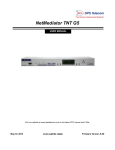
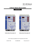
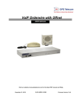
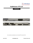
NetGuardian Discrete Expansion G4
USER MANUAL
Visit our website at www.dpstelecom.com for the latest PDF manual and FAQs.
December 1, 2010
D-OC-UM10C.01200
Firmware Version 4.0B
Revision History
January 31, 2002
User Manual released.
Supports NetGuardian firmware versions up to 2.6E
December 14, 2004
NetGuardian DX User Manual (D-OC-UM04C.14100)
released.
February 4, 2005
NetGuardian DX User Manual (D-OC-UM052.04300)
released.
July 7, 2006
NetGuardian DX User Manual (D-OC-UM067.07400)
released.
August 3, 2006
NetGuardian DX User Manual (D-OC-UM068.03410)
released.
March 22, 2007
NetGuardian DX User Manual (D-OC-UM073.22101)
December 1, 2010
Added FCC Notice for Class A Device
This document contains proprietary information which is protected by copyright. All rights are reserved. No part of this
document may be photocopied without prior written consent of DPS Telecom.
All software and manuals are copyrighted by DPS Telecom. Said software and manuals may not be reproduced, copied,
transmitted or used to make a derivative work, by either mechanical, electronic or any other means in whole or in part,
without prior written consent from DPS Telecom, except as required by United States copyright laws.
© 2007 DPS Telecom
Notice
The material in this manual is for information purposes and is subject to change without notice. DPS Telecom shall not be
liable for errors contained herein or consequential damages in connection with the furnishing, performance, or use of this
manual.
Contents
Visit our website at www.dpstelecom.com for the latest PDF manual and FAQs
1 NetGuardian Expansion Overview
1
1.1 Summary of Features
1
1.2 Introduction
1
2 Installation
2
2.1 Shipping List
2
2.2 Optional Accessories
2
2.3 Specifications
3
2.4 Hardware Installation
4
2.4.1
Site Preparation
4
2.4.2
Installation Steps Overview
4
2.4.3
Mounting Instructions
5
2.4.4
Power and Ground Connection
6
2.4.5
Communication Lines
8
9
2.4.5.1
NetGuardian Expansion Addressing
2.4.6
Discrete I/O Lines (alarms)
10
2.4.7
Fuse Alarm Pins and Control Relay Pinouts
11
2.4.7.1
2.4.8
Changing Jumper Options
Power-up
12
13
2.5 NGEdit Configuration
13
2.6 Web Browser Configuration
15
2.6.1
Logon
15
2.6.2
Configuring the Expansion Unit
15
2.6.3
Setting Up An Expansion Alarm
17
2.6.4
Setting Up a Relay
19
2.6.5
Monitoring the Expansion Alarm Points
21
3 Operation
21
3.1 Front Panel Functions
22
3.2 Display Mapping
24
4 Technical Support
26
1
1 NetGuardian Expansion Overview
1.1 Summary of Features
· Low cost method of expansion to existing NetGuardian 832A units (supported by NetGuardian G2, G4, and
others)
· Gives additional capacity over existing communications lines
· Helps conserve T/MonXM or IAM ports by reporting more alarms to the same address
· 48 ground activated discrete alarms per expansion
· 8 additional relay contact closures per expansion
· RS232 ports for easy daisy chaining between units
· LED indications of alarms and communications status
· Easy setup
DPS has kept the operation, pinout, and interfaces of the DX G4 model very similar to previous DX models.
You will find the new DX G4 very interchangeable with existing DX equipment.
1.2 Introduction
The NetGuardian Expansion box is a low cost, self contained device that provides the NetGuardian 832A with an
additional 48 ground activated discrete alarms per unit. With the capacity of adding up to 3 Net Guardian
Expansions, at 48 alarms points per unit, an additional 144 discrete alarms to the NetGuardian 832A can be
provided.
To make expansion a simpler and less expensive task, each unit is equipped with dual RS232 ports so that
additional Expansions can be daisy chained to one another. In this way, currently deployed NetGuardian 832As
can be easily expanded.
Fig. 1.2. NetGuardian Expansion functional diagram
2
2 Installation
2.1 Shipping List
NetGuardian Expansion
D-PK-NETDX-12022.00001
User Manual
D-OC-UM10C.01200
2, 23" Rack Ears
2 3/4 AMP fuse
RJ45 to RJ45 connection cable
D-PR-1028-10C-01 (1 per unit)
(for connection to
NetGuardian 832A G4)
2, 19" Rack Ears
Pads
DB9 to RJ45 connection cable
D-PR-1028-10A-01 (1 per unit)
(for connection to
legacy NetGuardian 832A)
8 3/8" Ear Screws
8 Washers
Zip ties
2.2 Optional Accessories
8' RJ45 to RJ45 connection cable
D-PR-1032-10B-08 (1 per unit)
(for connection to NetGuardian 832A G4)
Note: Please refer to Page 8 for pinout information
4 Rack Screws
3
2.3 Specifications
Physical Dimensions:
2 3/4" H x 17 1/4" W x 9 1/4" D
Mounting:
19" or 23" rack with supplied ears
Operating temperature:
41º – 95ºF (5º – 35ºC)
Power input:
–4 to –56 VDC
Optional wide range input: -20 to -70 VDC.
DPS Part# D-PK-NETDX-12026.00001.
Fuse:
3/4 amp GMT
Current Draw:
250mA
Interfaces:
2 - RJ45 connectors for RS232
2 - 50 Pin connectors for discrete alarms and control relays
Relays:
8
Protocol:
DCPX
Minimum NetGuardian
Firmware version required:
v1.5D
Options and Model numbers
Model number: D-PC-293-10A
FCC Compliance:
This equipment has been tested and found to comply with the limits for a Class A digital device, pursuant to part
15 of the FCC Rules. These limits are designed to provide reasonable protection against harmful interference
when the equipment is operated in a commercial environment. This equipment generates, uses, and can radiate
radio frequency energy and, if not installed and used in accordance with the instruction manual, may cause
harmful interference to radio communications. Operation of this equipment in a residential area is likely to cause
harmful interference in which case the user will be required to correct the interference at his own expense.
4
2.4 Hardware Installation
2.4.1 Site Preparation
Tools needed:
· Phillips screwdriver
· Small standard No. 2 screwdriver
· Wire strippers/cutters
!
Precaution
*
*
Pull fuses on source of -48VDC before connecting power.
Always observe electrostatic discharge (ESD) precautions.
2.4.2 Installation Steps Overview
· Mount hardware:
Mount NetGuardian Expansion in the rack.
· Connect alarms leads.
· Connect power.
· Provision NetGuardian 832A for NetGuardian Expansion
· Review NetGuardian Expansion status LEDs.
5
2.4.3 Mounting Instructions
The NetGuardian Expansion can be mounted in a 19" or a "23" rack by using different rack ears for each size.
Attach the appropriate size ears for your rack in the flush-mount locations shown in the figures below.
Fig. 2.3.3. The NetGuardian Expansion can be flush (top) or rear-mounted, as shown above.
Note: Rack ears can be flipped 180° for other mounting options not shown.
6
2.4.4 Power and Ground Connection
Fig. 2.3.4. Power connectors and fuses
The NetGuardian has two screw terminal barrier plug power connectors, located on the left side of the back
panel. (See Figure 2.3.4.)
Before you connect a power supply to the NetGuardian Expansion, test the voltage of your power supply:
·
Connect the black common lead of a voltmeter to the ground terminal of the battery, and connect the red
lead of the voltmeter to the battery's –48 VDC terminal. The voltmeter should read between –43 and –
53 VDC. If the reading is outside this range, test the power supply.
To connect the NetGuardian Expansion to a power supply, follow these steps:
1. Remove Fuse A and Fuse B from the back panel of the NetGuardian Expansion. Do not reinsert the
fuses until all connections to the unit have been made.
2. Remove the power connector plug from Power Connector A. Note that the plug can be inserted into the
power connector only one way — this ensures that the barrier plug can only be reinserted with the
correct polarity. Note that the –48V terminal is on the left and the RTN terminal is on the right.
3. Use the grounding lug to properly ground the unit.
4. Insert a battery ground into the power connector plug's right terminal and tighten the screw; then
insert a –48 VDC line to the plug's left terminal and tighten its screw.
5. Push the power connector plug firmly back into the power connector. If the power feed is connected
correctly, the LED by the connector will light GREEN. The LED by the power connector will be off if
the power feed is reversed.
6. Repeat Steps 2–5 for Power Connector B.
7. Reinsert Fuse A and Fuse B to power the NetGuardian Expansion. The front panel LEDs will flash RED
and GREEN.
To connect the NetGuardian to a power supply using a WAGO connector, follow these steps:
1. Remove the 2 fuses (A& B) from the back panel of the NetGuardian. Do not reinsert the fuses until all
connections to the unit have been made.
2. Remove the WAGO power connector. Note that the plug can be inserted into the
power connector only one way — this ensures that the barrier plug can only be reinserted with the
correct polarity. Note that the –48V terminal is on Slots 1 and 3 and the GND terminal is on Slots 2 and 4.
7
3. Use the grounding lug to properly ground the unit.
4. Insert a battery ground into the power connector plug's slots 2 and 4 by pushing down on top of the
appropriate slot of the WAGO connector with a screwdriver and inserting the wire into the slot, then releasing
the screwdriver. Insert a –48 VDC line to the plug's slots 1 and 3 using the same method as before.
Inserting a -48 VDC Line into Slot 1 of
WAGO Connector
5. Push the power connector plug firmly back into the power connector. If the power feed is connected correctly,
the LED by the connector will light GREEN. If the polarity of the power feed is reversed, the LED will not
illuminate.
6. Reinsert the fuses to power the NetGuardian. The front panel LEDs will flash RED and GREEN.
8
2.4.5 Communication Lines
1. Connect one end of the RJ45-RJ45 cable to reach through port number 7 (if NetGuardian 240T, use "serial"
port of 240T) located on the NetGuardian back panel.
2. Connect the other end of the RJ45-RJ45 cable to the “DX In” port of the NetGuardian Expansion (See Figure
2.3.5 below).
Note: If interfacing to the legacy NetGuardian G2 model, then use the supplied DB9-to-RJ45 cable instead.
If additional NetGuardian Expansions are to be installed:
3. Connect one end of another RJ45-RJ45 cable to the “DX Out” port in the first NetGuardian Expansion.
4. Connect the other end of that RJ45-RJ45 cable to the “DX In” port of the second NetGuardian Expansion.
5. To connect a third NetGuardian Expansion, repeat steps 3 and 4.
Note: The “DX IN” and “DX OUT” ports as well as the NetGuardian’s Data Ports are DCE type ports.
Fig. 2.3.5. NetGuardian Expansion with communications lines
Fig. 2.3.5. RJ45 Expansion Connection crossover cable pinout
Note: Connect the NetGuardian 240T RS232 serial port to the DX In port of the NetGuardian Expansion Unit.
9
2.4.5.1 NetGuardian Expansion Addressing
To distinguish NetGuardian Expansion Shelf 1 (and Shelves 2 and 3 if applicable), a DIP switch address setting
is used. The DIP switches use binary settings and are addressed as 1, 2, and 3 respectively. To verify the shelf
address, push and hold the ACK button on the front panel. The LEDs will indicate the shelf address (i.e. either 1,
2, or 3).
NetGuardian Expansion
DIP switch position
1
2
3 (Not used) 4 (Not used)
Shelf 1
On
Off
Off
Off
Shelf 2 (if applicable)
Off
On
Off
Off
Shelf 3 (if applicable)
On
On
Off
Off
Table 2.3.5.1. NetGuardian Expansion shelf addressing.
Fig. 2.3.5.1. Shelf addressing DIP switch close-up.
Note: If you only have one NetGuardian Expansion, it must be shelf 1. If a second NetGuardian Expansion unit
is used, it must be shelf 2, etc.
10
2.4.6 Discrete I/O Lines (alarms)
Discrete alarm points connected to the NetGuardian Expansion units are essentially single-lead signals
referenced to ground. The B-side of each alarm point is internally wired to ground, so either a single wire
bringing a contact to ground or a dry closure with the second lead connected to the B-side will be sensed as an
alarm signal.
Discretes 1-24
B
A
B
A
ALM 1
1
26
ALM 13
14
38
ALM 2
2
27
ALM 14
14
39
ALM 3
3
28
ALM 15
15
40
ALM 4
4
29
ALM 16
16
41
ALM 5
5
30
ALM 17
17
42
ALM 6
6
31
ALM 18
18
43
ALM 7
7
32
ALM 19
19
44
ALM 8
8
33
ALM 20
20
45
ALM 9
9
34
ALM 21
21
46
ALM 10
10
35
ALM 22
22
47
ALM 11
11
36
ALM 23
23
48
ALM 12
12
37
ALM 24
24
49
Table 2.3.6. NetGuardian Expansion discrete alarm points (continued on next page)
Discretes 25-48
B
A
B
A
ALM 25
1
26
ALM 37
14
38
ALM 26
2
27
ALM 38
14
39
ALM 27
3
28
ALM 39
15
40
ALM 28
4
29
ALM 40
16
41
ALM 29
5
30
ALM 41
17
42
ALM 30
6
31
ALM 42
18
43
ALM 31
7
32
ALM 43
19
44
ALM 32
8
33
ALM 44
20
45
ALM 33
9
34
ALM 45
21
46
ALM 34
10
35
ALM 46
22
47
ALM 35
11
36
ALM 47
23
48
ALM 36
12
37
ALM 48
24
49
11
2.4.7 Fuse Alarm Pins and Control Relay Pinouts
Fuse Alarm
The fuse alarm relay is Normally Open. If the fuse blows, the fuse alarm (FA) LED will light and the fuse alarm
relay (FA RLY) will de-energize (close). The relay is found on pins 13 and 25 of the DB 25 connector on the
back panel. Connect these pins to other alarm monitoring equipment to give visibility of an equipment failure
(see Figure 2.3.7 below). Refer to Table 2.3.7 for pinout information.
Control Relay
Controls can be used for starting or stopping equipment, unlocking doors, and other functions. Connect control
relays to the 25-pin connector on the back panel. Refer to Table 2.3.7 for control relay connection pinouts.
The default setting for the relays is Normally Open (N/O). To change the settings to Normally Closed (N/C), you
must reset the circuit board jumpers. For instructions on changing jumper settings, see Section 2.3.7.1.
Fig. 2.3.7. The Fuse Alarm relay is found on pins 13 and 25, and the Control Relay pins are numbers 1-8
Male DB25 Pin
Description
1
Relay 1 Common
2
Relay 2 Common
3
Relay 3 Common
4
Relay 4 Common
5
Relay 5 Common
6
Relay 6 Common
7
Relay 7 Common
8
Relay 8 Common
13
Fuse Alarm Relay Pin 1
14
Relay 1 (N/C or N/O)*
15
Relay 2 (N/C or N/O)*
16
Relay 3 (N/C or N/O)*
17
Relay 4 (N/C or N/O)*
18
Relay 5 (N/C or N/O)*
19
Relay 6 (N/C or N/O)*
20
Relay 7 (N/C or N/O)*
21
Relay 8 (N/C or N/O)*
25
Fuse Alarm Relay Pin 2
Table 2.3.7. Alarm and control relays pinout information
* This pin is user selectable by an internal jumper--the default is always Normally Open.
12
2.4.7.1 Changing Jumper Options
You can change the settings for control relays by resetting the jumpers on the NetGuardian's circuit board. To
open the unit and expose the circuit board, remove the screws from the top of the NetGuardian and lift the top
cover off. Figure 2.3.7.1 shows the circuit board and the location of the adjustable jumpers.
By default, all the adjustable jumpers are open, except for the speaker jumper. For control relay jumpers, the
open position corresponds to normally open operation, and the closed position corresponds to normally closed
operation.
Fig. 2.3.7.1. Control Relays on the NetGuardian DX circuit board
13
2.4.8 Power-up
Now that all alarm and communications wiring is complete, power up the unit by installing Fuse A and Fuse B in
the back panel.
2.5 NGEdit Configuration
NGEdit is the DPS-recommended way for configuring points on the NetGuardian DX. You can refer to the
NGEdit Help File or the NGEdit User Manual for full instructions. The following is to show you the screens you
would use to configure the NetGuardian DX.
Click the Ports tab to access the Options drop-down menu
14
Configure Your Selected DX with the Alarms Tab.
· When you click on the Expansion tab in the Alarms screen, enter the appropriate event in the Description field.
15
2.6 Web Browser Configuration
The NetGuardian offers Web Browser configuration for easy and convenient setup of the discrete alarms. The
NetGuardian supports Internet Explorer versions 4.0 and up and Netscape Navigator versions 4.7 and up.
2.6.1 Logon
1. After connecting to the NetGuardian's IP address, enter your password and click Submit (factory default
password is "dpstelecom"). (See figure 2.5.1)
2. In the main menu, there is a Monitor menu button and an Edit menu button. Most of the software
configuration will occur in the Edit menu.
Fig. 2.5.1. Enter your password to configure and monitor your NetGuardian's discrete alarms using the Web
Browser feature
2.6.2 Configuring the Expansion Unit
When you first logon, you will see the Alarm Summary window in Monitor Mode.
Alarm Summary Window in Monitor Mode
To configure your Expansion Unit, click on the Edit link on the bottom left-hand corner of the Alarm Summary
window.
16
1. Once you are in the Edit screen, click on 'Edit Ports'
2. Once in the Edit Ports screen, use the NGDdx drop-down menu in the Options section to select how many DX
units you will be working with. For this example, we will choose 1 DX unit.
Select Expansion Units from the NGDdx drop-down menu in the Options section
3. Click Submit Data
4. At this point, refresh the browser. You will see 2 new entries in the EDIT menu: Exp 1 Controls and Exp 1
Alarms.
There are 2 new entries in the Edit Menu after you select a DX in the Options Menu
17
2.6.3 Setting Up An Expansion Alarm
To configure an alarm for your expansion unit simply do the following:
1. Click on the Exp 1 Alarms link in the Edit Menu
The Exp 1. Alarms Window
2. Enter the desired alarm description and values
3. Click Submit Data
4. Exit to 'Monitor Mode' by clicking on the Monitor link in the upper-left hand corner of the screen.
18
5. The Alarm Summary window will show the newly-configured Exp 1. alarm.
The Alarm Summary Window showing a newly-active Exp.1 Alarm
6. Click on the Exp.1 Alarms link to view your alarm information.
19
2.6.4 Setting Up a Relay
1. Click on the Edit link in the bottom left-hand corner of the Alarm Summary Window.
2. Once in the Edit screen, click 'Exp 1 Controls'
3. Enter the description for the relay and click Submit Data
Enter Description Information to Configure Your Relay
4. You will see a 'Successfully Submitted' dialog box. Click OK.
5. Return to 'Monitor Mode' by clicking the Monitor link.
6. Click on 'Exp.1 Controls'
20
7. Select the OPR option under the 'State' drop-down menu.
To Activate The Relay, Select OPR
8. You should hear a clicking noise coming from your Expansion Unit confirming the relay.
21
2.6.5 Monitoring the Expansion Alarm Points
Now that the NetGuardian points have been provisioned with all of the appropriate information, they may be
monitored (this is helpful to verify the installation).
Connect PC to craft port on NetGuardian 832A, NOT the NetGuardian DX.
1. From the main menu, select C)onfig, then M)onitor, then A)larms, then E)xpansions.
2. Enter the display number that you would like to monitor (12=Expansion shelf 1, 14=shelf 2, and 16=shelf 3;
see section 3.2 for display mapping details).
3. The list of alarms and their status will be displayed, 16 alarms at a time. Press any key to scroll to the next
group of 16 items.
4. Press ESC to exit the monitoring list.
Monitor the Expansion points from the M)onitor, E)xpansions menu
3 Operation
22
3.1 Front Panel Functions
Fig. 3.1. The front panel displays alarm and communication status.
Label Descriptions
1. ACK button. The ACK button will acknowledge any new alarms (change of state (COS) alarms). It will also
cause the shelf address (determined by the back panel DIP switch) to be displayed by LEDs 1-3 when it is held
down.
23
2. Front panel LEDs. See Table 3.1 for LED indications.
LED
STATUS
Flashing Red
CFG
Flashing Green
LNK
DESCRIPTION
Invalid Shelf Address,
check front panel DIP
switch setting
Shelf Address set
correctly
Solid Green
Flashing Green/Red
Data Transmit/Receive
on primary RS232 port
(DX IN)
Flashing Green/Red Data Transmit/Receive
SEC
on secondary RS232 port
(DX OUT)
Green=Banks
A green flash indicates
the point bank number (16). A point bank is
comprised of 8 alarm
Alarms 1-8
points.
A red flash after the
green point bank number
Red=Points
flash indicates which of
the 8 alarms in that point
bank are in an alarmed
state (see table below).
Note: The Expansion
alarm points are also
displayed on the
NetGuardian's LCD.
Table 3.1. NetGuardian Expansion LED indications (above), and alarm point designations per point bank
(below)
PRI
Note: The silkscreen designations "DX IN" and "DX OUT" do not indicate communication direction.
Point Bank
1
2
3
4
5
6
Alarm Points
1-8
9-16
17-24
24-32
32-40
41-48
24
3.2 Display Mapping
Display numbers 1 through 11 in Table 3.2A correspond to the NetGuardian 832A, and Display numbers 12
through 17 (in bold) correspond to the NetGuardian Expansion unit.
Display
1
2
3
4
5
6
7
8
9
10
Description
Alarms 1-32
Ping Table
Analog Channel 1
Analog Channel 2
Analog Channel 3
Analog Channel 4
Analog Channel 5
Analog Channel 6
Analog Channel 7
Analog Channel 8
Relays/Housekeeping (See
11
NetGuardian 832A manual for
complete point descriptions
and table below)
12
NetGuardian Expansion 1
Alarms 1-48
12
NetGuardian 480 (as DX)
Alarms 1-64
13
NetGuardian Expansion 1
Relays 1-8 or NetGuardian
480 (as DX)
Relays 1-4
13
NetGuardian 480 (as DX)
Alarms 65-80
14
NetGuardian Expansion 2
Alarms 1-48
15
NetGuardian Expansion 2
Relays 1-8
16
NetGuardian Expansion 3
Alarms 1-48
17
NetGuardian Expansion 3
Relays 1-8
Table 3.2.A. NetGuardian 832A with NetGuardian Expansion Display Mapping
25
Display 11 Point
56
Description
NGDdx 1 Fail (Expansion
shelf 1 communication link
failure)
57
NGDdx 2 Fail (Expansion
shelf 2 communication link
failure)
58
NGDdx 3 Fail (Expansion
shelf 3 communication link
failure)
Table 3.2.B. NetGuardian housekeeping display 11 alarm points for Expansion communication link failures
26
4 Technical Support
DPS Telecom products are backed by our courteous, friendly Technical Support representatives, who will give you
the best in fast and accurate customer service. To help us help you better, please take the following steps before
calling Technical Support:
1. Check the DPS Telecom website.
You will find answers to many common questions on the DPS Telecom website, at
http://www.dpstelecom.com/support/. Look here first for a fast solution to your problem.
2. Prepare relevant information.
Having important information about your DPS Telecom product in hand when you call will greatly reduce the
time it takes to answer your questions. If you do not have all of the information when you call, our Technical
Support representatives can assist you in gathering it. Please write the information down for easy access.
Please have your user manual and hardware serial number ready.
3. Have access to troubled equipment.
Please be at or near your equipment when you call DPS Telecom Technical Support. This will help us solve
your problem more efficiently.
4. Call during Customer Support hours.
Customer support hours are Monday through Friday, from 7 A.M. to 6 P.M., Pacific time. The DPS Telecom
Technical Support phone number is (559) 454-1600.
Emergency Assistance: Emergency assistance is available 24 hours a day, 7 days a week. For emergency
assistance after hours, allow the phone to ring until it is answered with a paging message. You will be asked to
enter your phone number. An on-call technical support representative will return your call as soon as possible.
27
“Dependable, Powerful Solutions
that allow users to monitor larger,
more complicated networks with a
smaller, less trained staff”
“Your Partners in Network Alarm Management”
www.dpstelecom.com
4955 E Yale • Fresno, CA 93727
559-454-1600 • 800-622-3314 • 559-454-1688 fax