1
ENGAGE GI2 USER MANUAL
Revision v38
March 11
Notice
This document contains confidential and proprietary information of Verint Inc. and
is protected by copyright laws and related international treaties. Unauthorized use,
duplication, disclosure or modification of this document in whole or in part without
the written consent of Verint Inc. is strictly prohibited.
By providing this document, Verint Inc. is not making any representations regarding
the correctness or completeness of its contents and reserves the right to alter this
document at any time without notice.
© 2000-2011 Verint Inc. All rights reserved.
Contents
Revision History
No
Date
Author
Approved by
Date
3.7
4/05/09
DF
Inclusion of the Revision History
Changes
JK
4/05/09
3.8
14/05/09
DF
Minor Spelling Mistakes Corrected
JK
14/05/09
3.9
25/5/09
DF
PSC (UMTS) Clarification Page 20
JK
25/5/09
JK
27/7/09
JK
20/10/09
JK
23/2/2010
JK
16/6/2010
JK
1/12/2010
Revision History Format Changed
Bidi And Phone Locator Added
Filter Manager Added
25.20.3
3/7/09
DF
Target Isolator Added
Identities Grid Explanation Added
Small Inaccuracies Updated
Major Revision:
Spilt of Document into Core and Optional Components
Updated Identity Manager
Inclusion of Silent Call (GSM & UMTS)
Inclusion of Auto SMS
30.22.02
30/9/09
DF
Inclusion of Eavesdropper
Inclusion of Back Office new features
Inclusion of GCR Functionality Matrix
Menu Guide Update
Modes of Operation (GSM & UMTS) rewritten
Addition of Glossary
30.22.02
23/2/2010
DF
Update of Engage Gi2 System Pictures
Update of:
Ranconfig
Channelyser
ID Manger Context Menu
Identities Grid Menu
Functionality Matrix
34
16/6/2010
DF
License Information
Edit SMS on the Fly
Alphanumeric SMS
DTMF Interception
Figure Updates
Document Numbering Scheme
Update of:
UMTS Silent Call
White / Black List ID Manager Wildcards
Target Isolator (Multi Target)
36
1/12/2010
DF
Inclusion of:
Support for USSD
Dynamic Determination of Roles
Anonymous Phone
Periodic Update of Captured Phones
User Manual
1-3
Update of:
Range Mode
UMTS Custom Scan
GCR GUI Redesign
38
12/1/2011
DF
JK
Call to and Call From Target
Addition of Update Tx Button
Addition of GPS & Geolocation
Addition of Chinese Language Support
12/1/2011
Contents
1
2
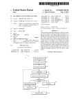
Hardware Description ..................................................................................................... 6
1.1
Engage Gi2 System Components ......................................................................... 6
1.2
Functional Description ........................................................................................... 7
1.3
Power Management ............................................................................................... 8
1.4
Heat Dissipation ..................................................................................................... 9
1.5
Operating System .................................................................................................. 9
1.6
Licensing ................................................................................................................ 9
1.7
RAN Configuration ............................................................................................... 10
1.8
Network IP Configuration ..................................................................................... 10
Engage Gi2 System Operation .................................................................................... 11
2.1
Starting the Manager Application ........................................................................ 11
2.2
Layout Manager ................................................................................................... 11
2.3
Channelyser ......................................................................................................... 12
2.4
RTX Control (Configuring Network Presets) ........................................................ 14
2.4.1
GSM RTX Control ............................................................................................ 16
2.4.2
UMTS RTX Control (Opt.) ............................................................................... 18
2.4.3
BTS LED Status Indicator (Where Available) .................................................. 18
2.5
Engage Gi2 Interrogation ..................................................................................... 19
2.5.1
Start Interrogation ............................................................................................ 19
2.5.2
Stop Interrogation ............................................................................................ 19
2.5.3
Interrogation Modes ......................................................................................... 20
2.5.4
Data Management ........................................................................................... 21
2.5.5
Closing the Application .................................................................................... 22
2.5.6
PDA Operation ................................................................................................ 22
2.6
Identities............................................................................................................... 23
2.6.1
Anonymous Phone Protection ......................................................................... 23
2.6.2
Periodic Update of Captured Phones .............................................................. 24
2.6.3
Identities Grid Menu ........................................................................................ 24
2.7
Identity Manager .................................................................................................. 29
2.7.1
Insert new identity ............................................................................................ 29
2.7.2
Edit identity ...................................................................................................... 30
2.7.3
Import Identities ............................................................................................... 35
User Manual
1
2.8
3
Optional Components................................................................................................... 37
3.1
3.1.1
4
5
2
RF Calculator ....................................................................................................... 35
SMS (Opt.) ........................................................................................................... 37
USSD Interception ........................................................................................... 37
3.2
Fake SMS (Opt.) .................................................................................................. 37
3.3
Alphanumeric SMS (Opt.) .................................................................................... 38
3.4
Edit SMS on the Fly (Opt.) ................................................................................... 38
3.5
Scheduler (Opt.) .................................................................................................. 39
3.6
Silent Call – GSM & UMTS (Opt.) ....................................................................... 42
3.6.1
GSM Silent Call ............................................................................................... 42
3.6.2
UMTS Silent Call ............................................................................................. 43
3.7
Target Isolator (Opt.) ........................................................................................... 45
3.8
GSM Call Routers - GCRs (Opt.)......................................................................... 47
3.9
‘Make Call To’ Target (Opt.) ................................................................................ 52
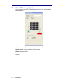
3.10
‘Make Call From’ Target (Opt.) ............................................................................ 53
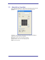
3.11
Phone Correlator (Opt.) ....................................................................................... 54
3.12
Auto SMS (Opt) ................................................................................................... 56
3.13
Eavesdropper (Opt) ............................................................................................. 57
3.14
Channelyser Logger (Opt) ................................................................................... 60
3.15
GPS & Geolocation (Opt) .................................................................................... 61
Data Analysis................................................................................................................. 63
4.1
Back Office (Data Manager) ................................................................................ 63
4.2
Select From.......................................................................................................... 64
4.3
Find ...................................................................................................................... 65
4.4
Search Results .................................................................................................... 66
4.5
File Menu ............................................................................................................. 67
4.6
View Menu ........................................................................................................... 67
4.7
Tools Menu .......................................................................................................... 67
Appendices .................................................................................................................... 69
5.1
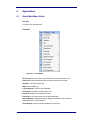
Quick Main Menu Guide ...................................................................................... 69
5.2
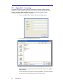
Appendix 2 – Identity Manger – Import Functionality .......................................... 75
User Manual
5.3
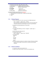
Appendix 3 – Wireless LAN (VNC) Configuration (Opt.) ..................................... 76
5.3.1
Initial Network Set-up - Laptop ........................................................................ 76
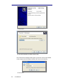
5.3.2
Initial Network Set-up - PDA ............................................................................ 77
5.3.3
VNC Operation ................................................................................................ 80
5.3.4
Restoring VNC Viewer on the Handheld PDA ................................................. 82
5.4
5.4.1
Appendix 4 - Power Amplifier (Opt.) .................................................................... 84
PA Operating Instructions ................................................................................ 84
5.5
Appendix 5 – TAC Database Update .................................................................. 85
5.6
Appendix 6 – Software Installation ...................................................................... 86
5.6.1
Precautions ...................................................................................................... 86
5.6.2
Database Backup ............................................................................................ 86
5.6.3
Software Removal ........................................................................................... 87
5.6.4
Software Installation ........................................................................................ 87
5.7
Appendix 7 – Licensing........................................................................................ 92
5.8
Appendix 8 – Back-up and Recovery of Hard Drive ............................................ 94
5.8.1
Hard Disk Back-up ........................................................................................... 94
5.8.2
Hard Disk Recovery ......................................................................................... 94
5.9
5.9.1
5.10
Appendix 9 – Remote Sessions .......................................................................... 95
Laptop Configuration ....................................................................................... 95
Appendix 10 – Antenna Specifications ................................................................ 96
5.10.1
External Antennas ........................................................................................... 96
5.10.2
Internal Antennas........................................................................................... 105
6
Glossary ....................................................................................................................... 106
7
Known Issues .............................................................................................................. 108
User Manual
3
Figures
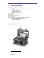
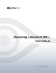
Figure 1-1.1: Engage Gi2 Multi BTS Version .............................................................................. 6
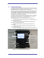
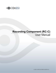
Figure 1-2.1: ‘A’ System, Open Attaché Case View ................................................................... 7
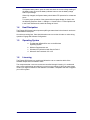
Figure 1-2.2: ‘M System, Open View ............................................................................................ 8
Figure 2-1: Help-About License ................................................................................................ 10
Figure 2-1.1: Manager Screen ................................................................................................... 11
Figure 2-2.1: Layout Manager .................................................................................................... 11
Figure 2-3.1: Channelyser User Interface ................................................................................. 12
Figure 2-3.2: UMTS Custom Scan pop-up dialogue box ......................................................... 13
Figure 2-3.3: Options Drop down menu .................................................................................... 14
Figure 2-4: Channelyser Applying Presets ............................................................................... 15
Figure 2-4.1: Preset configuration ............................................................................................. 16
Figure 2-4.2: UMTS RTX Control ................................................................................................ 18
Figure 2-5.3.1: GSM Modes ........................................................................................................ 21
Figure 2-6.1: Identities Grid – Protect Anonymous ................................................................. 23
Figure 2-6.3.1: Identities Grid – Right Click Options ............................................................... 24
Figure 2-6.3.2: Identities Grid – Field Explanation ................................................................... 26
Figure 2-7: Identity manager ...................................................................................................... 29
Figure 2-7.2: Identity Manager – Handset Tab ......................................................................... 30
Figure 2-7.3: Identity Manager – Using Wildcards ................................................................... 31
Figure 2-7.4: Identity Manager – Media Tab.............................................................................. 32
Figure 2-7.5: Identity Manager – Filters Tab ............................................................................. 33
Figure 2-7.6: Identity Manager – Alerts Tab.............................................................................. 34
Figure 2-8: RF Calculator............................................................................................................ 36
Figure 3-1: SMS grid ................................................................................................................... 37
Figure 3-2: Identities grid – Fake SMS functionality................................................................ 38
Figure 3-3: Fake SMS from Alphanumeric Characters ............................................................ 38
Figure 3-4.1: Edit SMS selectable in ID Manager ..................................................................... 39
Figure 3-4.2: Edit SMS Pop-up on arrival of SMS .................................................................... 39
Figure 3-4.3: SMS is Edited and Forwarded ............................................................................. 39
Figure 3-5.1: Scheduler User Interface ..................................................................................... 40
Figure 3-5.2: Session Designer User Interface ........................................................................ 40
Figure 3-5.3: Task Editor User Interface ................................................................................... 40
Figure 3-6.1: GSM Silent Call User Interface ............................................................................ 42
Figure 3-6.2: UMTS Silent Call ................................................................................................... 44
Figure 3-6.3: UMTS Silent Call User Interface .......................................................................... 44
Figure 3-7.1: Target Isolator - Paging ........................................................................................ 45
Figure 3-7.2: Target Isolator - Captured .................................................................................... 45
Figure 3-7.3: Target Isolator – Status Change.......................................................................... 46
Figure 3-8.1: GCR Operational Concept ................................................................................... 47
Figure 3-8.2: GCR Manager ........................................................................................................ 48
Figure 3-8.3: GCR Functionality Matrix ..................................................................................... 49
Figure 3-8.4: Calls Tab ................................................................................................................ 51
Figure 3-11.1: Phone Correlator Probing .................................................................................. 54
Figure 3.11.2: Phone Correlator – Network & LAC selection.................................................. 54
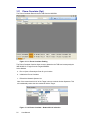
Figure 3-11.3: Phone Correlator Results .................................................................................. 55
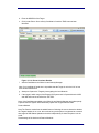
Figure 3-11.4: Check Presence Results .................................................................................... 56
Figure 3-12.1: Auto SMS ............................................................................................................. 56
Figure 3-13.1: Send Advertising ................................................................................................ 57
Figure 3-13.4: Multiple Targets - real MSISDN must be used ................................................. 59
Figure 3-13.5: Eavesdropper Settings – Calling Numbers ...................................................... 59
Figure 3-13.6: Eavesdropper Settings – Advertising ............................................................... 60
Figure 3-14.1: Channelyser Logs ............................................................................................... 60
Figure 3-14.2: Channelyser Log Details .................................................................................... 61
Figure 3-15.1: GPS of Unit .......................................................................................................... 61
Figure 3-15.2: GPS of Target ...................................................................................................... 61
Figure 3-15.3: NMRs of Target ................................................................................................... 62
Figure 3-15.4: GPS of Unit on Map ............................................................................................ 62
Figure 4-1: Back Office ............................................................................................................... 63
4
User Manual
Figure 4-2: Back Office - Search ................................................................................................ 64
Figure 5-1.1: View Menu ............................................................................................................. 69
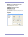
Figure 5-1.2: Options Menu ........................................................................................................ 70
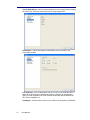
Figure 5-1.3: Country Filter ........................................................................................................ 71
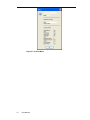
Figure 5-1.4: About Menu ........................................................................................................... 74
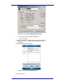
Figure 5-3.1: Laptop TCP/IP Settings ........................................................................................ 76
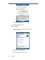
Figure 5-3.2: PDA Wireless Card Settings ................................................................................ 77
Figure 5-3.3: PDA IP Settings ..................................................................................................... 78
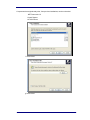
Figure 5-3.4: PDA Enable WLAN ................................................................................................ 78
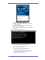
Figure 5-3.5: PDA Connecting to Network ................................................................................ 79
Figure 5-3.6: Laptop Connection Confirmation ....................................................................... 79
Figure 5-3.3.1: Laptop Starting VNC .......................................................................................... 80
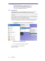
Figure 5-3.3.2: Laptop modifying VNC Properties ................................................................... 81
Figure 5-3.3.3: PDA Connecting to VNC ................................................................................... 81
Figure 5-3.3.4: PDA Changing View .......................................................................................... 82
Figure 5-3.3.5: PDA Control of Manager ................................................................................... 82
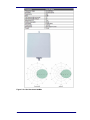
Figure 5-10.1 Omni directional 900Mhz (Short) ........................................................................ 96
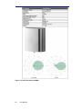
Figure 5-10.2 Omni directional 1800Mhz (Short) ...................................................................... 96
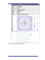
Figure 5-10.3 Uni directional 900Mhz ........................................................................................ 97
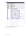
Figure 5-10.4 Uni directional 1800Mhz ...................................................................................... 98
Figure 5-10.5 Omni directional 900Mhz (Long) ........................................................................ 99
Figure 5-10.6 Omni directional 1800Mhz (Long) .................................................................... 100
Figure 5-10.7 Directional 2100Mhz .......................................................................................... 101
Figure 5-10.8 Shark antenna – Quad Band ............................................................................. 104
User Manual
5
1
1.1
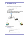
Hardware Description
Engage Gi2 System Components
The Engage Gi2 system comprises the following components:
Samsonite Attaché case; or
Explorer Trolley Case; or
c. Rack Mount system including
Laptop computer
BTS base-station
Battery and power control system
Flat panel antennae
GSM and/or UMTS terminal for base station monitoring (Channelyser)
1
d. Pocket-PC handheld computer (optional )
e. Power amplifier (optional)
f. Power related external accessories including:
Laptop power supply/charger
Battery charger
Direct power supply (desktop power supply)
Pocket-PC battery charger
a.
b.
Figure 1-1.1: Engage Gi2 Multi BTS Version
1
6
For a concise list of available options and variations please contact your Agent
User Manual
1.2
Functional Description
The Engage Gi2 System incorporates a base-station transceiver (RTX) connected
to the laptop computer via LAN interface. Communication is carried out through flat
panel directional antennas mounted on the top cover of the case.
The laptop runs all control, management and network simulation software required
for the operation of the system. The laptop incorporates a built-in wireless LAN
module enabling remote operation of the system while the case is closed by using
a handheld PDA. The GSM/UMTS terminal allows retrieval of essential network
information for easy configuration of the system.
The Engage Gi2 System is powered by two separate power sources. The laptop is
powered by its internal battery; the RTX and GSM/UMTS terminal operate on a
dedicated battery located on the top cover inside the case lid.
The Engage Gi2 System comes in many different forms, all made to order.
‘A: GSM Band Only, Single BTS with a Convertor. i.e. two Bands mounted
within Samsonite Attaché case
3’D: GSM & UMTS, Single BTS with a Convertor and a Single Node-B
mounted with in Samsonite Attaché case
‘M: GSM Only Multiple BTS (no Convertors) mounted within Explorer
Tactical Case
’M: GSM & UMTS, Multiple GSM BTS and/or Multiple Node-B mounted
within a Explorer Tactical Case
3’R GSM & UMTS Multiple GSM BTS and/or Multiple Node-B in Rack Form
Battery Charge Ports
Antenna Panel
Battery
Laptop
Antenna Ports
Input Voltage Indicator
Channelyzer
BTS Status LED
Fan Switch
PA Ports
On / Off Switch
Power Socket
Figure 1-2.1: ‘A’ System, Open Attaché Case View
User Manual
7
Antenna Panel
Battery
Antenna & PA Ports
On / Off Switch
GPS Port
Laptop
Figure 1-2.2: ‘M System, Open View
1.3
Power Management
The Engage Gi2 System is designed for two main modes of operation:
a. Static operation where mains power (110/220 vAC) is
available
b. Static viechle operation where 12vDC is avialble
c. Battery power during portable or covert operation
During static operation, plug the DC connector of the Engage Gi2 System
(desktop) power supply into the power (PS) socket. Once plugged, the power
indicator will light. While the Engage Gi2 System power supply is connected.
Connect the laptop charger/power supply to ensure that the laptop’s battery
remains fully charged.
To charge the System battery, plug the Engage Gi2 System battery charger into
the System battery charge socket. You may charge the Engage Gi2 System battery
while it is operating on the external power supply. However, when the system is
transmitting, do not connect or disconnect the power supply plug or the AC voltage
supply thereof.
Note, the 3’D & ‘D Models’ Batteries take charge directly from the Unit and no
additional charging is required. i.e. The Battery is charged via the ‘D unit and NOT
directly.
The Engage Gi2 System battery operation may take place when the case is closed
and all power supplies and chargers are disconnected. When operating the unit,
periodically monitor the status of both the laptop’s battery and the System battery.
You may monitor the laptop’s battery status via the PDA. To monitor the Engage
8
User Manual
Gi2 System battery status, open the case and check the current voltage reading of
the battery meter or press the battery indicator button to see the battery charge
status in percentage.
When fully charged, the System battery should allow RTX operation for at least two
hours.
To ensure proper operation of the system while the laptop display is closed, click
the following sequence: Start => Settings => Control Panel => Power Options and
in the Power Schemes tab, switch all settings to ‘Never’.
1.4
Heat Dissipation
The Engage Gi2 System internal power amplifier generates heat in the electronic enclosure
underneath the base plate.
Al units have cooling fans. Care should be taken not to cover the air intake or outlet during
operation. Engage Gi2 Software Configuration
1.5
Operating System
a. The Manager & Backoffice runs on the Windows
Operating System.
b. Minimum Requirements are:
c. Windows XP Professional with Service Pack 3
d. Microsoft .Net Framework 2.0 or 3.5
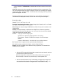
1.6
Licensing
The Engage Gi2 System is a modular and allows the user to customise which of the
software components is available to them.
The components that a user can access are controlled through Licensing. It is understood
that a users requirements upon delivery or over time may change. If this is the case please
contact your Agent for details of what software is available / compatible and how to upgrade
your current system.
User Manual
9
Figure 2-2: Help-About License
Throughout this User Manual the software / hardware modules that are optional (some of
which you may have taken) are marked with (Opt.).
1.7
RAN Configuration
For software versions 25.20 and above several setting configuration changes are made
through a tool call “RAN Configuration Tool”.
Note: RANCONFIG is only to be modified under the supervision of the Training and Support
Engineers as the incorect value could cause damage to the system
1.8
Network IP Configuration
The laptop IP Configuration should not be modified. Doing so can cause your
system to stop working.
Note: any connection to the internet should be made via WiFi and not using the
Ethernet Adapter.
10
User Manual
2
2.1
Engage Gi2 System Operation
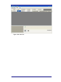
Starting the Manager Application
To start the Manager, double-click the Icon on the desktop.
The Manager screen will appear, the appearance will vary according to your
individual Unit’s Configuration.
Figure 2-1.1: Manager Screen
2.2
Layout Manager
In order to take advantage of the dynamic GUI, it is possible to load and save
different layouts so as to customise how you wish the Engage Gi2 System to look.
Six different default layouts are configured in advance:
•
•
•
•
•
•
Interrogation
Channelyser
Silent Call
PDA
Call Router
Scheduler
Figure 2-2.1: Layout Manager
User Manual
11
Save: allows the user to save a desired GUI configuration
Load: loads the selected layout
Delete: deletes the selected layout
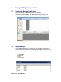
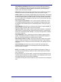
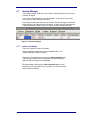
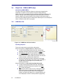
2.3
Channelyser
The Channelyser option integrates the System with a multi-band (GSM and/or
UMTS) terminal, capable of monitoring the received signal strength of the
surrounding network/s detected. The Channelyser user interface presents the user
with all the information essential for configuration of the Engage Gi2 System. The
information is presented both in textual form as well as a graphical representation
of the Broadcast Control Channels.
Available
networks
Serving
cell info
Neighbour cells
channel allocation
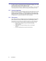
Figure 2-3.1: Channelyser User Interface
a. Available networks: contains the names of the Networks
received upon running a Scan
b. Neighbour cells info: contains channel (ARFCN)
numbers of serving cell and several neighbour cells, each
with their respective received signal strength (in dBm),
Location Area Code, Cell Identity and C1, C2 properties. 2
c. The graphical representation of the received BCCH
channels displays the channel strength and the channel
number. The channels belonging to each network operator
appear in the same colour as in the network operators list.
In order to increase channels visibility, it is possible to
enlarge an area of the band by simply selecting it. A rightclick, Unzoom option will display the whole band agian.
d. The type of scan selected will remain the default one until
another selection is made.
Scan all bands performs complete RF scanning of all available
(GSM & UMTS) channels that the system supports and displays
the frequency utilization.
2
C1 and C2 parameters are available on GSM operator scan mode only
12
User Manual
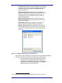
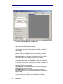
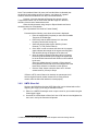
Custom Scan all performs complete GSM scan of all available
Channels, that the system supports, and UMTS channels that
have been found in any previous scan, then displays the
frequency utilization.
GSM - Spectrum Scan (Full scan) performs complete RF
scanning of all Channels configured on your particular System3.
In case the Channelyser is not properly connected / or not
connected at all, an error message will pop up “Unable to
connect to Channelyser”.
GSM - Continuous Scan monitors a certain operator and
displays dynamically the network changes of the serving cell
and its list of neighbours.
UMTS- Band scan performs complete RF scanning of all
UMTS channels and displays the frequency utilization
UMTS- Custom scan performs complete RF scanning of all
UMTS channels that have been found in ANY previous Scan.
These can be selected as required in order to reduce the time
of the scan.
Figure 2-3.2: UMTS Custom Scan pop-up dialogue box
Upon starting of the Channelyser, the module scans for all available GSM/UMTS
networks in the area. All networks are presented in the leftmost area.
a. The Channelyser uses the network information retrieved
during the scan to suggest possible RTX configuration
parameters for BA List mode interrogation. The suggested
configuration is automatically populated into the network
drop-down box in the RTX Control area.
3
For a concise list of available options and variations please contact your Agent
User Manual
13
b. By clicking the Channelyser button in the RTX Control
area, the user may select Channelyser suggested
configuration for each of the networks previously scanned
by the Channelyser. Once selecting a Channelyser
suggested configuration, the user may manually override
the settings by changing the value(s) in the respective text
box and clicking the Update button.
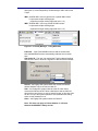
The Channelyser Tools menu enables the following options:
c. Free Channels: checks the RF activity over the specified
GSM/UMTS channel. Channels with measured RF activity
below -100 dBm are reported as free by being displayed
Green. Red means the channel is in use.
d. Load to Ran: Adds Free channels to the Neighbours List
of that particular RAN. This is used primarily for GSM
Silent Call.
Figure 2-3.3: Options Drop down menu
e. Expert Mode: is affecting Operator Scan and Continuous
scan. When selected, the action will return the usual
results, plus additional information for the cells in the list,
like BA list or Status. Not all the cells will return full
information when interrogated.
f. GSM Bands: offers the ability of selecting which band
should be visible in the graphical representation of the
Channelyser.
g. UMTS: offers the ability to view \ hide UMTS band
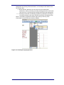
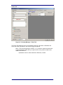
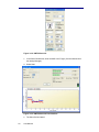
2.4
RTX Control (Configuring Network Presets)
RTX Control is the area where the user defines the transmission parameters that
will be sent to the BTS. Currently, the Manager supports single and multiple BTS
kits. For each BTS owned, the user will be allowed to set the presets parameters
by selecting View->RTX Control-> desired BTS or by selecting the tab at the
bottom left of the Manager.
There are two types of BTS:
1. GSM
2. UMTS - 3G
The interfaces of these two types are different, due to the different network
properties.
There are two modes of operating:
14
I.
Manual selection
II.
Channelyser selection
User Manual
Manageable by selecting Preset radio button, or Channelyser radio button on the
RTX Control form.
I.
Manual selection allows the user full control over the transmission
parameters, either by selecting an already existing preset from the Presets
drop down list, or by entering all the details by hand and start transmitting.
II.
Channelyser mode will automatically populate the parameters according to
the internal selection rules of the channels returned by Channelyser scan.
Note: It is possible to populate the RAN by right clicking on the any of the
Channelyser’s results’ fields and selecting ‘Update’.
Figure 2-4: Channelyser Applying Presets
User Manual
15
2.4.1
GSM RTX Control
Figure 2-4.1: Preset configuration
Presets: The name you enter is for management and user interfaces
purposes only and will not be transmitted to the mobile phones
connected to the Engage Gi2 System. The name displayed on the
mobile phone screen is a function of the Country Code and Network
Code only.
By using the right-click operation, a context menu is displayed and the
user is able to operate on the presets list:
Add: Adds a new preset to the list
Clone: Clones the currently existing preset, under another
name
Delete: Deletes currently selected preset from the list
Rename: Renames the currently selected preset
The context menu is disabled while transmitting or if you work in
Channelyser mode.
Mode: Accept or Reject mode of transmitting. (See Section 2.5.3)
SMS Ack: SMS "Acknowledgement" mode:
16
User Manual
o
Fail – notifies the sender that sending the SMS failed regardless of
the real result.
o
Success - notifies the sender that sending the SMS succeeded
regardless of the real result.
Operator: Select Operator.
Country Code: Enter the 3-digit Mobile Country Code (MCC) of the
network you wish to operate. This box will be filled automatically when
choosing an Operator (1)
Network Code: Enter the Mobile Network Code (MNC) of the network
you wish to operate. This box will be filled automatically when
choosing an Operator (1)
Channel: Enter the channel number or Absolute Radio Frequency
Number (ARFCN) allocated to the present network.
Location Area: Enter the Location Area Code (LAC) you wish to
transmit. Make certain that the value you select is different than the
value currently used by the actual mobile network active in the area
where the System is operated.
In the event that you have previously used the Engage Gi2 System in
Reject mode on the present network, you must select a different
location area code than the one previously used.
Power: Select the desired transmit power. The power is varying
between Maximum power and Minimum power in -2db steps.
Neighbours: To set the adjacent cells transmitted by the Engage Gi2
System write the ARFCN in the box, right click and choose "Add To
List". To remove a specific Neighbour choose its ARFCN, right click
and choose "Remove From List". It is possible to choose up to 32
neighbour cells for each RTX control.
Output port: select the output port to be used by the Engage Gi2
System. When transmitting via the unit’s internal antennas select
“Internal Antenna” and while using an external power amplifier, select
“Power Amp”.
Auto Update: If selected, when the user clicks Transmit button, the
System will run an Operator Scan (against the operator selected in
the preset) and update the ARFCN and LAC. The System will
automatically start transmission after the scan has finished.
Update: When selected the transmission and the Preset are both
updated.
Update Transmission: When selected only the transmission is
updated. i.e. not the Preset.
Note: the parameters listed above can be altered on-the fly, i.e. while
transmitting, by using the Update button for the change to take effect.
Also, note that once a preset has been updated the preset is ‘saved’
in this configuration. Therefore, when restarting Manager the latest
saved Config is used. This remains true for Scheduled Tasks as well,
the preset last saved prior to the execution of the Schedule is used.
User Manual
17
2.4.2
UMTS RTX Control (Opt.)
Figure 2-4.2: UMTS RTX Control
Presets: [Refer to GSM RTX Control - Presets]
Operator: [Refer to GSM RTX Control - Operator]
Country Code: [Refer to GSM RTX Control - Country Code]
Network code: [Refer to GSM RTX Control - Network code]
LAC (Location Area Code]: [Refer to GSM RTX Control - LAC]
Channel: Enter the UMTS channel number (Use the Channelyser results)
PSC (Primary Synchronisation Code): Scrambling codes are used to identify
cells (sectors). Each cell is assigned a unique primary scrambling code – between
0-511.
Standby \ Transmit: Start \ Stop transmit
Update: Updates the Transmission on the fly and updates the Preset.
UpdateTransmission: Updates the Transmission on the fly and does NOT update
the Preset.
2.4.3
BTS LED Status Indicator (Where Available)
GSM BTS’ have an LED that indicates its status. The LED can be seen through the
slot cut into the top plate of the Engage Gi2 System.
Flashing Red – Powered Only
Flashing Green – Initialised but not Transmitting
Continuous Green – The BTS is Transmitting
Note: UMTS Node-Bs do not have an LED Indicator
18
User Manual
2.5
Engage Gi2 Interrogation
2.5.1
Start Interrogation
Switch ON one, or more of the connected RTX Hardware.
b. Start the Manager application.
c. After starting the application, the default presets will be
selected and ready to use on all RTX Control panels.
However, the user can select different preset from the
drop-down box and also manually change the presets or
add new ones.
d. Select the required operation mode from the "Mode" drop
down box in the RTX control window.
e. Verify "Show Rejected", "Show Identities" and "Join same”:
are checked in the "Identities" window.
f. Click the Initialize button in the RTX controls you wish to
transmit on, to start the network simulator and establish the
required connections with the RTX hardware.
Within a few seconds you may notice that the GSM Network Simulator icon
appears and the Manager waits for the establishment of a connection from the
RTX hardware, as follows:
Observe the status bar and the messages on the bottom of the Manager
window.
The first status message should indicate: "Network Started".
A few second after the following message will appear “RTX Initializing”.
After initialization is complete, the RTX switches to the Ready state and the
"Standby (Ready for operation)" will be displayed, and the Standby button
will change to Transmit.
Click the Transmit button in order to start interrogation sequences on all the
RTX controls you want to capture.
The System status bar will now indicate “RTX ON” and handsets subscribed to
the selected networks will start registering.
Each handset that registers will include a line within the "Identities" window
table..
It is possible to change the "Channel" property while transmitting.
After changing the channel, click the "Update" button.
a.
2.5.2
Stop Interrogation
It is possible to stop, one by one, all running transmissions. However,
you can only stop some of the running simulations and leave the
others operating.
To stop transmission, select desired RTX Control and click the
Standby button
b. Once the Standby button is clicked, interrogation is disabled
and the RTX hardware is switched to the Standby state.
c. You may now resume transmission by clicking the Transmit
button again or switch to another network by clicking the
Network drop-down box and\or changing each network
properties.
a.
User Manual
19
2.5.3
Interrogation Modes
The Engage Gi2 System supports different Modes of interrogation. Although here
are some commonalities between the Modes in GSM and UMTS it is easier to think
of each of them as distinct and separate. The different features and functions are
detailed below.
2.5.3.1 GSM & UMTS Modes of Operation
GSM - Reject Mode
When interrogating in Reject mode, the Engage Gi2 System rejects all registration
attempts of unknown GSM handsets after collecting their IMSI, IMEI and other
data. The Handsets will re-register with an available Commercial Network.
GSM - Accept All Mode
When interrogating in Accept mode, the Engage Gi2 System accepts the
registration attempts of all GSM handsets within range of the Network. Once
accepted to the System network, a temporary local phone number (MSISDN) is
allocated, for the present session only. One registered handsets may call another
one by dialling any automatically assigned temporary number. (Private Network)
Note: Once rejected, a given handset shall typically not attempt to register again
with the System unless the location area code is modified.
GSM - Accept – short range
When interrogating in ‘Accept – short-range’, the Engage Gi2 System accepts the
registration attempts of all GSM handsets up to 100 meters. Just as with ‘Accept
All’ Once accepted to the System network, a temporary local phone number
(MSISDN) is allocated, for the present session only.
Phones out of range will be rejected and NOT be displayed and NOT stored in the
database. This includes phones in any of the Lists, (White or Black).
GSM - Accept – mid-range
When interrogating in ‘Accept – mid-range’, the Engage Gi2 System accepts the
registration attempts of all GSM handsets up to 550 meters. Just as with ‘Accept
All’ Once accepted to the System network, a temporary local phone number
(MSISDN) is allocated, for the present session only.
As with ‘Accept short range’, Phones out of range will be rejected and NOT be
displayed and NOT stored in the database. This includes phones in any of the
Lists, (White or Black).
GSM – Denial of Service (DoS)
When interrogation in DoS Mode the Engage Gi2 System first collects the IMSI,
IMEI etc then rejects the handset. The Handset will NOT re-register back to the
commercial network until it is powered off and on again. (Hard Reject)
Note: Use with Extreme Caution.
20
User Manual
Figure 2-5.3.1: GSM Modes
UMTS – Reject Mode
Handset information is gathered. i.e. IMSI, IMEI, distance approximation, then the
Handset is return to the commercial UMTS network.
Note: In order to cause the Handset to re-register to the System both the LAC and
PSC must be changed.
UMTS – Blocking Mode
(Parallels can be drawn with the GSM ‘Accept Mode’.)
All Handsets camp on the System, they do not have commercial network access.
As each Handset performs its Location Update they appear White in the Identities
Grid.
UMTS – Denial of Service (DoS)
Handset information is gathered. i.e. IMSI, IMEI, distance approximation, then the
Handset is Hard Rejected. It must be powered off then on again before it will reregister with any network.
Note: Unlike GSM this is currently for ALL phones – this cannot be performed on a
selected Handset like GSM, but is valid for Dual Mode phones as well. In addition,
roaming phones may register to a different network.
UMTS – Move to GSM
Handset information is gathered. i.e. IMSI, IMEI, distance approximation, then a
single Handset can be told to register to the GSM channel on which the System is
Transmitting, thus allowing for further manipulation.
UMTS – Move All to GSM
Handset information is gathered. i.e. IMSI, IMEI, distance approximation, then all
Handsets are instructed to register to the GSM channel on which the Engage Gi2
System is Transmitting.
Note1: UMTS only phones return to the commercial network at the end of the
System Transmission.
2.5.4
Data Management
All interrogation sessions are recorded in a MySQL Database for retrieval and data
analysis.
User Manual
21
To make it easier to extrapolate the data collected by the System, it is crucial
that the Operation Name and Place Name be given.
Note that all session information is logged upon clicking “Standby”. The user needs
to manually advance the session number according to the operational scenario.
2.5.5
Closing the Application
Ensure all transmission have been stopped and click the top-right close icon on the
Manager to close the application. The Manager Application window closes and so
does the GSM Network Simulator icon. The RTX hardware’s status indicator light
(applicable to some ‘A’ units only) may briefly switch to red colour and then switch
to orange colour. It is now safe to switch OFF the RTX hardware.
2.5.6
PDA Operation
Once a VNC connection is established between the handheld PDA and the laptop
(refer to Section 5.3), switch to "PDA" layout in the "Layout Manager" window.
Once started, the user interface and operational sequence is quite similar to the
operation from the laptop console. However, several points should be noticed:
a. Response time through the VNC link is slower than laptop
console operation.
b. PDA display size required scrolling in order to view all data
received.
c. Use the virtual keyboard to enter text into text boxes.
22
User Manual
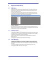
2.6
Identities
This window will show all the different identities captured by the Engage Gi2
System and all their relevant parameters.
The accepted identities have a white background, while the rejected ones have an
orange one, thus making it easy to distinguish the suspects from the regular
identities. If a special entry, as defined in Identity Manager, is captured by Engage
Gi2 System, the entry in the Identities display will have the colour as defined by the
user to make it even more prominent. The SMS grid and Back Office records are
also coloured according to the Identity Manager.
Once the interrogation has been stopped, all the captured IDs will be filled with
dark orange colour in order to separate between previous and current
interrogations.
If an entry is greyed out, means that the mobile station did not receive a response
last time it was paged which could indicate the mobile moved out of range or was
turned off (IMSI Detach).
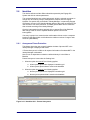
2.6.1
Anonymous Phone Protection
This feature allows the user to specify whether the data of phones NOT in the
Identity Manager is displayed and stored.
If ‘Protect Anonymous’ is ON then all captured information of handsets NOT in the
Identity Manager is discarded.
Note: this is not dependant on whether a defined Identity is in the White or
Blacklist.
Protect Anonymous is set under the ‘Settings’ tab.
1. When the option is turned off, the following applies:
a. All anonymous phones are displayed in Identities grid
b. All anonymous phones data is saved to the database
2. When the option is turned on, the following applies:
a. No anonymous phones are displayed in Identities grid
b. No anonymous phones data is saved to the database
Figure 2-6.1: Identities Grid – Protect Anonymous
User Manual
23
2.6.2
Periodic Update of Captured Phones
The Identities Grid shows which phones are stil currently registered to the Engage
Gi2 System by performing a periodic Update. This applies for the first ten phones
to be captured that have entries in the ID Manager.
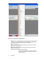
2.6.3
Identities Grid Menu
By right clicking on any captured Identity the following Menu is displayed.
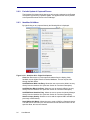
Figure 2-6.3.1: Identities Grid – Right Click Options
Clear List: Removes the current captured handsets from the display. Note,
handsets are not deleted from the historical database. This can only be done
through the Back Office.
Add/Edit/Delete White List Entry: Allows the user to access the White List entry
directly from the Identities Grid. (See later Section for Functional Description)
Add/Edit/Clear Black List Entry: Allows the user to access the Black List entry
directly from the Identities Grid. (See later Section for Functional Description)
Add/Edit/Delete Identities Entry: Allows the user to access the Identity Manager
directly from the Identities Grid. (See later Section for Functional Description)
Attach to empty identity: Allows the user to add the captured IMEI and IMSI to a
previously created Identity.
Send SMS to this Mobile: Allows the user to send an SMS to a Captured Identity.
The SMS can be sent with up to 700 Characters and the Senders number can be
specified. Note, this must be Licensed.
24
User Manual
Send SMS from this Mobile: Allows the user to send an SMS from Captured
Identity. The Captured Target must be able to be Cloned. The SMS can be sent
with up to 700 Characters and will appear to be sent from the Cloned phone’s
number. Note, this must be Licensed.
Silent Call: User can initiate a Silent Call Directly from the Identities Grid. Please
see Silent Call section for further description. Note, this must be Licensed.
Isolate Target: User can Isolate a Target Directly from the Identities. This removes
the User from the Commercial Network by adding them to the White List, changing
the LAC and placing them on a Clear Channel. The Clear Channel is defined by
the user by adding it to the Neighbour Cells field in the RTX Control Window. Note,
this must be Licensed.
Clone Target / Dedicate Router: This Function becomes available with a GCR.
For a Captured Identity the options Clone Target (Bidi) or Dedicate Router (Uni)
are available. See the GCRs section for detailed description. Note, this must be
Licensed.
Extract MSISDN: Allows the user to determine the Captured Target’s MSISDN. A
USB Sim reader is required. Note, this must be Licensed.
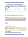
Page this mobile: After a target is initially captured by the System it is possible to
check whether it is still being held. Paging the target shows the 3 measurements,
all three are the Downlink power readings. i.e. the signal strength that the handset
receives the System at.
Force Registration: This is a quick way to cause a handset to register with the
System. This adds the Handset to the White List and automatically changes the
LAC, thus causing the handset to re-register with the System.
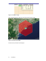
Show Capture Position on map: This function shows the location of the system
when the Target was captured. This functionality works using 3rd party mapping
software that must be configured to read and write data to the mapping com ports
of the unit.
Send Advertising: Allows the user to send an Audio File to the target thus
initiating a Call for the purposes of Eavesdropping. See Eavesdropper Section.
Note, this must be Licensed.
NOTE: The availability of the above options depends on the status of Target. i.e.
the mode you are transmitting in (Accept or Reject), what Ciphering the handset
uses, Licensing etc.
By right clicking on any column header, a context menu pops up allowing the user
to select only the information he wants to display. This configuration will be saved
and loaded next time the user opens the application.
It is possible to change the columns order for a more convenient use, just drag and
drop.
User Manual
25
Figure 2-6.3.2: Identities Grid – Field Explanation
History: The ‘+/-’ (expand/collapse icon in the left side of the entry) allows the user
to visualize the history of that handset. Currently, the Engage Gi2 System keeps
the history of the last 10 times a specific device was captured.
ID: Not Implemented Yet
IMSI: the phone’s International Mobile Subscriber Identity (IMSI) of the SIM card
within the interrogated handset.
IMEI: The International Mobile Entity Identity (IMEI) representing the handset’s
manufacturer serial number.
E\S\T: refers to Equipment\SIM match and displays
-
26
User Manual
E\S if the identity was captured in 2 different places of the
same operation at least 2 times with the same SIM in the
same Mobile Station.
-
E\S if the identity is defined in the Identity Manager with the
exact combination of IMSI\IMEI, regardless of operation
and places it is seen.
-
E if the identity was captured in 2 different places of the
same operation at least 2 times with the same Mobile
Station, but different SIM card.
-
S if the identity was captured in 2 different places of the
same operation at least 2 times with the same SIM card,
but different Mobile Station.
-
T (TMSI Match) only used for Phone Correlator
-
Blank if none of the above.
S Matches: indicates how many times the user has been captured with its last
saved IMSI.
E Matches: indicates how many times the user has been captured with its last
saved device (Equipment).
Operation Matches: indicates how many times the target was captured in this
particular Operation and Place.
Join Count: is operational after Join Same checkbox has been
checked, it counts the number of occurrences joined together. You will
see only one entry for a specific IMSI/IMEI combination and a number
displaying how many times, during the same transmission, the
System has seen it. This is valid when the ‘Place’ has been changed
before Transmitting.
RAN: specifies the RAN on which the target was captured on.
RAN Net: the current transmission MCC + MNC the target was captured with.
Name: displays the name under which the identity is registered in Identity
Manager, blank otherwise.
Group: The type of Identity this Handset belongs to.
Last LAC: shows the previous LAC the phone was registered to. It can display a
real network LAC or previously simulated System LAC.
[Not applicable for UMTS].
No.: counts the identities captured in the same session.
Time: the exact time (HH:MM:SS AM/PM) of each mobile phone registration.
Handset: the manufacturer and phone model of the captured phone, based on the
IMEI’s Type Approval Code (TAC)
Operator: the captured SIM’s network operator, based on the SIM’s actual
MCC/MNC
Distance: gives the distance range within which the handset is likely to be found.
Minimum and Maximum distance is shown.
MSISDN: displays the MSISDN of an accepted phone if entered in the ID Manager.
If the Handset does not have an entry , a system generated one will be attached,
starting from 1000 and incrementing with 1 each time a new device is accepted. If
the device is rejected, the System will not attach it an MSISDN.
[Not applicable for UMTS]
Operation and Place: The project label assigned to the specific activity. While
expanding the History list, these columns may display different operations and
places where this identity has been seen.
User Manual
27
Notes: displays the notes (if any) defined for the target in the Identity Manager,
blank otherwise.
TMSI: the registered users original (initial) TMSI.
A5/1: Indicating whether or not the captured phone support A5/1 algorithm
[Not applicable for UMTS]
A5/2: Indicating whether or not the captured phone support A5/2 algorithm
[Not applicable for UMTS]
RX Lev: the signal strength measurement of the phone’s signal
GPS Data: See Section GPS & Geolocation Public No.: Displays the
Public Number (if any) as entered in the ID Manager
Status: Indicates whether a Handset has been ‘Isolated’ (See Isolate
Targets)
(U)ARFCN: Displays the Channel on which the identity was captured.
28
User Manual
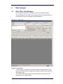
2.7
Identity Manager
The Identity manager enables the user to define "Special identities" such as team
members or targets.
You can set extra information for specific identities, such as name, sound alert,
colour, picture, SMS notification and notes.
Every captured phone that will match an identity in this list will trigger a visual alert
holding the photo and the extra text information, an audio alert (the sound defined
in Sound field) and an SMS alert to the number provided in the specific field.
Figure 2-7: Identity manager
2.7.1
Insert new identity
There are 2 options to insert new identity:
Open the identity manager and press the "Insert" button – the
"Identity Properties" window will open.
Right click on a captured phone and select "Add to Identities List"
The identity edit window will be opened with the selected phone's
IMSI and IMEI and ready to be edited/filled.
Note that adding a MS using the "Add to Identities List" function
populates some of the fields for you, therefore, it is recommended to
use this option if possible.
User Manual
29
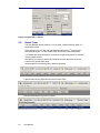
2.7.2
Edit identity
Handset Tab
Figure 2-7.2: Identity Manager – Handset Tab
Name – Set a new identity name or select one of existing names to
add another IMSI/IMEI to the same identity.
Group – Set the type of Identity this Handset belongs to. New groups
can be created and then become available in the drop down menu of
each Identity.
MSISDN: System assigned MSISDN. Can be modified by the User.
Colour – Set a colour to appear whenever said identity is displayed.
Notes – Add note to be attached to the identity.
Auto Clone Identity – if the Target is captured and a GCR available
then this Identity will be automatically Cloned by the system.
Auto Extract MSISDN – if the Target is Captured and a BiDi is
available then the Targets real MSISDN will be extracted. Additionally
the MSIDN will be added to the identity where both IMSI & IMEI match
in the phone number (public network) field. If no match is found then a
new identity will be created (License Dependent) Note: IMSI must be
defined for this option to be available.
Auto Silent Call – when selected and a Target Captured the System
will automatically start the Silent Call.
Edit SMS on-the-fly: When selected any Incoming or Outgoing
SMS’s will appear in a pop-up box giving the user the option to Edit or
Block the SMS.
Enable Eavesdropper – (Eavesdropper Application Only) if the
Target is Cloned (and makes a call) or Advertising sent then the
Eavesdropper function is initiated. See Eavesdropper section for full
30
User Manual
description. (License Dependent). Global setting for ANY calls for this
Target.
IMSI – Set\Edit IMSI. User may provide full or partial IMSI number.
% represents multiple missing digits
_ represents a single missing digit (total must = 15)
IMEI – Set\Edit IMEI. User may provide full IMEI number.
% represents multiple missing digits
_ represents a single missing digit (total must = 15)
Figure 2-7.3: Identity Manager – Using Wildcards
Public No. - If the ‘Real’ MSISDN is known add the number here.
Note that MSISDN Extraction automatically adds the found number
here.
Hide Caller ID – The user can override the Target’s Handset settings
and choose to hide or show the Targets ID to the commercial network.
Default – the Engage Gi2 system allows the commercial network
decides whether to show or hide the caller ID
Hide – the Engage Gi2 system hides the caller ID. Note: Some
commercial networks do NOT allow a Handset to hide the Caller ID,
this may be a paid service or only by special request. In this case calls
will fail. It is up to the system Operator to check whether this setting
works on their networks or not.
Show – the Engage Gi2 systems shows the Caller ID
Note: This does not apply to Private Network. In a Private
Network the MSISDN is always shown
User Manual
31
Media Tab
Figure 2-7.4: Identity Manager – Media Tab
Image – Add picture to the identity. Selected image will appear
whenever the identity is captured.
Audio – Add sound alert to be played when the said identity is
captured.
32
User Manual
Filters Tab
Figure 2-7.5: Identity Manager – Filters Tab
The Filters Tab allows the User to view whether a target is in the White or Blacklists and
hence the mode of operation in the event the target is captured.
Note: i) The Lists are specific to one BTS. i.e. if you wish to capture and retain the
Target regardless of which BTS you capture them on they must be added to the
White List of all BTS’s.
ii) Handsets can be in either the White or Black list, not both.
User Manual
33
Alerts Tab
Figure 2-7.6: Identity Manager – Alerts Tab
SMS Alert (Opt.) – there is a possibility to send an SMS alert to a
specific phone at the moment the identity was captured. For this
option to work there is a need to insert a valid SIM card to the USB
Modem. It is necessary to use a SIM card of a Network other than the
Network on which the interrogation is taking place, ensure there is no
PIN enabled and that the SIM has credit or on contract.
Active – Globally Enables or Disables the SMS Alerts
Recipient – The MSISDN to which the SMS Alert will be sent for any
of the Notify Events.
On Call – SMS Alert sent if the Target makes any outgoing call, (not
implemented yet)
On SMS - SMS Alert sent if the Target sends an SMS, (not
implemented yet)
On Capture - SMS Alert sent if the Target
On Contact – SMS alert when target calls or receives call from
specified number, (not implemented yet).
34
User Manual
Calls Tab
Incoming & Outgoing Call Connect & Redirect to - not currently
implemented.
Block – All Incoming or Outgoing Calls to or from the Target are
blocked. The call is automatically hung up with a call disconnected
message.
2.7.3
Import Identities
Import Identities allows the user to import already existing identities defined in a
CSV file.
Please refer to the later Section for the format the CSV file must have.
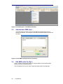
2.8
RF Calculator
The RF Calculator Function allows a user to determine the RF Frequency of a
particular Channel or the Channel and Band of a particular frequency.
By entering any single ‘known’ value the rest of the associated parameters are
populated.
User Manual
35
Figure 2-8: RF Calculator
36
User Manual
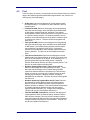
3
3.1
Optional Components
SMS (Opt.)
Shows all the SMS’ caught by the Engage Gi2 system. The System captures the
SMS sent from inside the simulated network and the SMS coming from the real
network if the target is cloned.
Join Same option makes sure that, if the phone retries several times to send the
same SMS, due to the personal settings of the device, the user can hide all these
retries and note the actions in the Join Count incremental field.
Figure 3-1: SMS grid
By right-click on any column header, a context menu pops up allowing the user to
select only the information he wants to display. This configuration will be saved and
loaded next time the user opens the application.
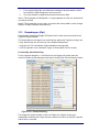
3.1.1
USSD Interception
Unlike SMS messages, USSD messages create a real-time connection during
a USSD session. The connection remains open, allowing a two-way exchange
of sequence of data with the commercial network.
USSD is often used for Call back services, Prepaid balance queries and
balance top-ups.
The Engage Gi2 system also Intercepts these messages.
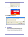
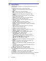
3.2
Fake SMS (Opt.)
Fake SMS option allows the user to send a message to a captured target, while
pretending to be somebody else who sends it. Practically, the user can provide in
the Number field any phone number to be displayed on the target’s mobile display
as sender.
This facility is available by right-clicking on the captured target’s entry, then
selecting “Send SMS to this mobile” menu option.
User Manual
37
Figure 3-2: Identities grid – Fake SMS functionality
3.3
Alphanumeric SMS (Opt.)
This Option allows the user to send a Fake SMS from Alphanumeric (not just
Numeric) Characters. The Reciepent of the SMS sees that the SMS is from the text
as written.
Figure 3-3: Fake SMS from Alphanumeric Characters
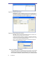
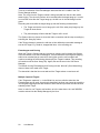
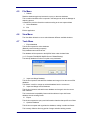
3.4
Edit SMS on the Fly (Opt.)
Once a Target is Cloned any Incoming or Outgoing SMS’s can be modified before
passing it onto the intended Recipient.
This functionality can be set for each Target individually within the ID Manager.
38
User Manual
Figure 3-4.1: Edit SMS selectable in ID Manager
Figure 3-4.2: Edit SMS Pop-up on arrival of SMS
Figure 3-4.3: SMS is Edited and Forwarded
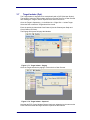
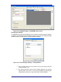
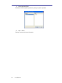
3.5
Scheduler (Opt.)
The Scheduler functionality is useful for users that need to transmit on different
operators, or for those that need to cycle transmission between two or more
networks and want to do this in an automated way. It is an easy way to save the
presets from the beginning and load them as tasks that are part of a session.
To run a session, select an entry in the session tree and clicking on the Start
Session button.
User Manual
39
Figure 3-5.1: Scheduler User Interface
Add Session: a session comprises of a list of one or several tasks that will
be launched at specific time stamps and that will run for a given duration.
The tasks can be defined to run on different RAN’s or the same RAN. Tasks
that run on the same RAN cannot have overlapping times.
Figure 3-5.2: Session Designer User Interface
Add Task: a task is a single action that will be executed on the RAN. The
user needs to provide a unique name to each task.
A Task uses a Preset of conditions. Therefore it is necessary to define the
Preset as well. This can be done by modifying the Variables under a Preset
in the RTX Control and then Updating that Preset.
Note, if a Task is scheduled and at any time in the future the Presets are
modified, the modified presets are used.
Figure 3-5.3: Task Editor User Interface
Only one session can be run at a particular point in time per BTS. The user will get
a notification if the RAN’s are already transmitting, being allowed to continue the
operation (possible stopping the current transmission) or not. If the RAN’s involved
are not initialized, the Scheduler will perform this action prior to starting executing.
40
User Manual
For the Scheduler to Run Correctly the following Checks should be made:
• The Preset has been named, variables set and Updated.
• A task using a particular RAN and Preset is defined.
• Tasks using the same RAN do not have a time overlap.
• A Session has been created containing one or more Tasks.
• The Session has been started.
User Manual
41
3.6
Silent Call – GSM & UMTS (Opt.)
Introduction (GSM & UMTS)
The Silent Call function allows the System to activate any target phone’s
transmitter as a beacon for the purpose of direction finding (homing).
While a silent call is in progress, the phone display remains as in standby mode.
However, during a silent call the target phone is disconnected from the real
network, shifted to an unused channel ("Clear Channel”) and cannot make or
receive any calls. Different phone models behave differently if the user attempts to
make a call while a silent call is in progress.
3.6.1
GSM Silent Call
Figure 3-6.1: GSM Silent Call User Interface
Operating Sequence
There are 2 sequences to start the silent call process:
Silent call sequence on Reject mode and a different LAC:
•
In order to effectively generate silent calls, the Manager
application should be configured to operate in Reject mode
•
Set a different LAC than the real operator and transmit
•
The target phone’s IMSI or IMEI should be included in the
White List so as to capture it within the System and allocate
a phone number, as defined in the White List.
•
Once the target phone has been captured by the Engage
Gi2 System, start the Silent Call console, from the toolbar or
by right-clicking on the target row (on the table) and
selecting “Silent Call”.
Silent call sequence on same LAC (Immediate Silent Call):
•
In order to effectively generate silent calls, the Manager
application should be configured to operate in the same
LAC as the real operator
•
Start the silent call from the tool menu, although the target
and no other phone are displayed (while operating on the
same LAC, phones will just "camp" on the Engage Gi2
System cell rather than register on it, meaning that they will
not be displayed, however it will be possible to page them) .
42
User Manual
Note: The Immediate Silent Call (same LAC and No White List Needed) has
the benefit of having being quicker to Capture, can Capture of a greater
distance and does not stand out from the Commercial Network.
However, it has the downside of Blocking ALL phones until the
Target answers when it is not even known that the Target is in the area,
therefore, it has a lack of awareness as well.
When deciding between using Accept or Reject Mode these factors
should be taken into consideration.
[See “Operational Field Craft for Further Details”]
Proceed with the following, once silent call console is displayed:
a. Enter the targets IMSI (if required) or select from available
Targets in the ID Manager
b. Enter\Verify that the shifted channel is in the same
frequency band as the serving cell.
c. Select the desired channel type: SDCCH (Control
Channel) 4or TFR (Traffic Channel)
d. Click “Start” in order to activate the silent call. A progress
graph indicates the strength of the signal received (uplink
and downlink) during the progress of the silent call.
e. Once the target is captured and silent call is in progress,
the serving cell simulated by the Engage Gi2 System will
be as the shifted channel and will remain so until modified
by the user.
Since the "shifted channel" is usually a "Clear channel",
the registration process will seem to be stopped due to the
fact that this channel is unfamiliar to other phones.
f. Click the "Stop" button to stop the silent call. It will take
several second (~25 sec) to stop it.
If Return to RTX control Channel is checked, the presets panel will
hold its original Channel number instead of the homing channel
number, after the Silent Call window is closed properly.
3.6.2
UMTS Silent Call
Similar to the GSM Silent Call the UMTS Silent Call can be initiated without first
capturing the Target, just as long as the IMSI is known.
a. Either run a UMTS Channelyser scan or open a scan for your location using the
Channelyser Logger
b. Set the RTX Control Mode to Silent Call. Use a PSC that is in the Neighbour list
but is not in use by the Commercial Operator
4
Preferred method when utilizing both Spectrum Analyzer and Icom homing devices
User Manual
43
Figure 3-6.2: UMTS Silent Call
c. In the Silent Call Window, enter the IMSI of the Target. (Can be selected from
the Identity Manager)
d. Select Start
Figure 3-6.3: UMTS Silent Call User Interface
e. The Silent Call is Initiated
44
User Manual
3.7
Target Isolator (Opt.)
The Target Isolator is designed to be used primarily with a GCR (See later Section).
The benefit of using the Target Isolator is that it moves the Target to a Clear Channel
thus allowing the Target to remain captured even while on the move.
Once the Target is Captured e.g. in the White List -> Right Click -> Isolate Target
Select the Ran to which the Targets should be moved
Enter the previously determined Clear Channel (Use the Channelyser Graph and
Check Channel Function).
The Engage Gi2 System will page the Handset.
Figure 3-7.1: Target Isolator - Paging
Once the Target answers the paging it is moved to the Clear Channel.
Figure 3-7.2: Target Isolator - Captured
Note that the RTX Control Window Channel has been updated to be the same as the
Clear Channel and that the target has been captured on that channel.
User Manual
45
Figure 3-7.3: Target Isolator – Status Change
a. Isolating Target: light (bright) orange – indication when starting isolation
b. Target isolated: light pink
c. Unsuccessful: white if stays on source RAN – as Accepted. Target moves
back to this state if isolation fails after 3 retries.
Note: Target Isolation can be applied to multiple targets simultaneously. In this case
the Right Click Menu is available for additional Targets, that, if selected are moved
to the same Clear Channel. This applies for Multiple BTS systems only.
46
User Manual
3.8
GSM Call Routers - GCRs (Opt.)
[Not currently available for UMTS handsets]
Introduction
GCR’s come in many types, they can come in the following combinations:
•
Outgoing call GCR (Unidirectional GCR)
•
In\ Out going call GCR (BiDirectional GCR)
•
Single \ Multiple modems
Unidirectional GCR (UNI)
The GSM Call Router (GCR) kit and application enable the Engage Gi2 System to
route a voice call originated by a target phone captured by the System to the real
GSM network via the GCR kit. In this mode, the SIM card inserted into the GSM
terminal in the GCR kit is billed for the calls made by the target.
Figure 3-8.1: GCR Operational Concept
Operating Sequence
Verify the Uni is Off
b. Insert a SIM Card. It is recommended that the SIM be on
‘Contract’ or ‘Post-Paid’. Pre-Paid can be used but there is
a risk of running out of credit. The SIM should also not
have any PIN Codes set.
c. Keep the Uni a distance of 1m or greater away from the
BTS.
d. Place the antenna in a good location. I.e. High and Far
away from the System and Uni. Good reception can be
verified by observing the RxLev on the Uni GUI. The
a.
User Manual
47
Antenna should also be placed on a metal surface as this
greatly improves the range.
e. Turn on and Initialise the Uni
Figure 3-8.2: GCR Manager
Initialize: operation will detect all the GCR’s attached to the unit and connect
them to the available, already initialized, RAN’s.
Bidirectional GCR (BiDi)
The BiDi incorporates all the functionality of the Uni-GCR but can work with
Incoming calls as well. By emulating the Target’s SIM and extracting the Kc,
which is used for ciphering calls, the phone can be ‘Cloned’ by the system.
Note that a phone can be cloned with the BiDi if it supports A5/2 Encryption. If
the Phone supports A5/1 Encryption only then a separate additional system is
required.
If Bidi Random Mode is Enabled:
- GCR automatically allocates Scanners for all active networks. If a scanner cannot be
allocated immediately it will be allocated when a modem is available.
-
Target Mode is allowed
If Bidi Random Mode + Uni is Enabled:
-
GCR automatically creates unidi for outgoing calls from targets whos ciphering
cannot be broken. i.e. A51 Targets when only A52 breaker is available.
If Bidi Random Mode is Enabled & Uni Random Mode Disabled:
- Outgoing call from a target with unbreakable Kc is possible only in target mode
(Dedicate router)
If Bidi Random Mode is Disabled:
- No Scanner is allocated.
- Bidi operations are possible only in target mode (Clone target)
If Bidi Random Mode is Disabled & Uni Random Mode Enabled
- GCR dedicates unidis from all available SIM readers. (it doesn’t happen if bidi
random mode is enabled see above)
48
User Manual
- Unidi calls are served by the dedicated unidis.
If all Random Mode disabled:
- Only target mode is available (Clone target, Dedicate router). All random mode
operations are dropped.
DTMF Interception:
During any call the DTMF Tones are automatically intercepted. These are visable in
the ‘Call Window’ for that particular call.
Core Functionality Matrix
Function
Incoming SMS
Description
Intercepted (Can be Forwarded to Target)
System
Only
System +
Uni
System +
BiDi
Outgoing SMS
Intercepted (Can be Forwarded to Recipient)
Viewed Only (not Forwarded to Recipient)
Send Fake SMS
To Captured Handset
From Captured Handset to any Recipient
Incoming Calls
To the Captured Handset
Outgoing Calls
(Note:Uni has Caller ID withheld)
Fake Calls
Make Outgoing Calls from Targets Handset
Make Calls To
Make incoming Calls to Targets Handset from
Laptop
Make Calls From
Make Outgoing Calls from Targets Handset using
Laptop
Private Network
Voice and SMS
Possible
Not Possible
Figure 3-8.3: GCR Functionality Matrix
The following menu items are common to all GCR’s.
Connections Tab:
RxLev: represents the Real network Rx Level as observed by the GCR Modem
Note: the status indicator turns green after the GCR has been properly detected and
initialized. The indication is shown as a green triangle on the Modem in the bottom left
User Manual
49
of the Connections Tab.Reinitialize: reinitializes the GCR and connects it to the active
RAN’s.
Calls Tab: holds the list of the recorded and unrecorded call of the current session. The
calls can be played within the Engage Gi2 System. All calls ever recorded by the System
can be found under: C:\Program Files\...\AudioCalls\ and can be played with any external
player that supports .wav files.
The Engage Gi2 System supports multi GCR system. All the GCR’s detected during
Initialization will be displayed as boxes similar to the one in the previous example.
From Left to right...
Identity: The ID of the Target in the call.
Incoming / Outgoing Call Indication. Arrow pointing right is Outgoing call i.e. call made
by Target. Arrow pointing left is Incoming Call.
Other Party: Non captured target’s MSISDN. Note: Caller ID may not be available for all
Incoming calls.
Activity: Call Signal Strength, Call Duration and DTMF Tones. White box goes Bold
when tones are sent. Hover over the box to see the Tones. Note: they are also available
in the Calls Tab once the Call has ended.
Control:
Hang-up - Ends the ongoing Call
Speaker Icon - Mutes the Laptop speaker for this call only
Eavesdropper - Enables / Disables Eavesdropper. See Eavesdropper
Section.
Release to Real Network – Hands the call over to the Real Network
DL: Downlink level, the power that the system sees the Real Network
UL: Uplink level, the power that the System sees the Captured Target
Network: the MCC and MNC of the network currently registered to, or Unknown if the
modem is not on a network.
a.
After the GCR is properly initialized and connected to the real network, calls can
be performed from within the System.
When the target dials a number, the action will be visible in the Log of the Call
Router Manager as well as in the personal log of the designated GCR.
b.
50
After the call has finished, the log file will display an appropriate message and
the recording will be listed and ready to be played in the Calls Tab. Audio files
are stored as wav files under C:\Program Files\...\AudioCalls\ directory
User Manual
Figure 3-8.4: Calls Tab
User Manual
51
3.9
‘Make Call To’ Target (Opt.)
A call can be made directly to a captured Target (incoming call) using the laptop
Mic and Speakers.
‘Call from’: can be any number the System operator chooses.
Mic Volume: volume of the users (laptop) microphone
Speaker Volume: volume of the users (laptop) speaker
DTMF: is sent an received.
Note: even when the speaker volume is muted, both sides of the conversation are
recorded.
52
User Manual
3.10
‘Make Call From’ Target (Opt.)
When a Bidi GCR is available, (i.e. Target can be cloned.) then a call can be made
from the captured Target’s phone (outgoing call) using the laptop Mic and
Speakers.
‘Call from’: is the real number of the person the user wishes to call FROM the
targets Phone. (Caller ID will not be withheld)
Mic Volume: volume of the users (laptop) microphone
Speaker Volume: volume of the users (laptop) speaker
DTMF: is sent an recieved.
User Manual
53
3.11
Phone Correlator (Opt.)
The Phone Correlator Determines the TMSI from the MSISDN.
Figure 3-11.1: Phone Correlator Probing
The Phone Correlator function allows a user to determine the TMSI and consequently the
IMEI & IMSI of a Target from the Targets MSISDN.
Active Method
a. Run or Open a Channelyser Scan for your location
b. Initialise the Phone Correlator
c. Refresh the Network Operator List
Note: If the network and/or LAC of the Target is known uncheck all other Operators. This
will considerably reduce the time needed to find the Target.
Figure 3.11.2: Phone Correlator – Network & LAC selection
54
User Manual
d. Enter the MSISDN of the Target
e. Click Locate Phone. Once a likely Candidate is found the TMSI has now been
identified.
Figure 3-11.3: Phone Correlator Results
f.
Add the Candidate to the White List and Identity Manager.
Note: If no candidate is found then it is possible that the Target is not in the LAC or has
their handset switched off.
g. Attempt to Capture the Target by interrogating the Local Network
h. If the target is within range of the Engage Gi2 System and is Captured then the IMSI
and IMEI will now be identified from the TMSI.
Note: If the Candidate was added to the White list and Identity Manager and subsequently
Captured then the System will automatically update the Targets IMEI and IMSI.
Passive Method
Note The Passive method has the added feature of allowing the user to determine whether
the Targets handset is on or not, this works as long as the phone is registered to a network
that supports SMS Status Updates and works independently of where the phone is in the
world.
Disadvantage of the Active and Passive Methods
User Manual
55
The disadvantage of the active method is that the targets phone might ring, the system has
an inbuilt emergency stop if this is detected.The disadvantage with the Passive method is
that if a network charges for SMS reception this may show on the bill.Note: The Phone
Correlator should always be tested using a Test phone with Netmonitor. This is to ensure
any possible chance that the Target is alerted be prevented.
Check Presence
If the Commercial Network supports Silent SMS and Delivery Report then whether the
Target’s phone is on or not can be determined.
Again, this must be tested before using Operationally.
Figure 3-11.4: Check Presence Results
3.12
Auto SMS (Opt)
Auto SMS allows to user to send a particular message to Captured Handsets from
any MSISDN of the users choosing.
Figure 3-12.1: Auto SMS
56
User Manual
I.
For a particular RAN the user defines the message to be sent and the number
from which the SMS will appear to have been sent.
II.
Once any Handset is Captured the system will send the SMS.
Note 1) This funtionality is RAN Specific. i.e. target captured on a Ran not ‘checked’ will
not recieve an SMS
Note 2) This functionality can be used in conjuction with ‘Accept Mode’ to send a single
SMS’s to multiple Handsets simultaneously.
3.13
Eavesdropper (Opt)
Eavesdropper enables the Engage Gi2 System User to listen and record audio from a
Captured Target’s handset*.
This functionality turns a target’s own mobile phone against the Target by turning it into
a “bug” & allows the user to have even more situational awareness.
* Currently over 70% of handsets / SIM combinations are supported
** GCR is required if to be used whilst Target is Cloned (Work with Uni as well)
Functionality: Send Advertising
For any Captured handset i.e. in the White List, the Engage Gi2 System User can
choose to initiate the Eavesdropper manually by choosing the ‘Send Advertising’ button.
Figure 3-13.1: Send Advertising
The Engage Gi2 System initiates a call to the Target, the Target’s phone rings.
Independent of whether the Target chooses to answer the call or not the Mic is opened
and all audio is recorded.
User Manual
57
There is an indication of the Eavesdropper status and the call is visible in the Call
Router Manager window.
Note: The voice from the Target’s mobile is being recorded from the time the mobile
starts ringing. The voice will continue to be recorded after the target hangs up. In order
to record the voice after the Target hangs up, the Mic icon in the call dialog must be
green.
Recording the sound after the target hangs up has the following characteristics:
•
The Target must be the one to hang up the call. If the other party hangs up, the
Target will hear silence.
•
The phone display will show that the Target is still in a call.
The System User can choose to close this Audio connection and thus stop recording by
selecting the ‘Hang Up’ button.
If the Target chooses to answer the call then a User defined pre-recorded message is
sent to the Target. E.g. Dead air, dropped dial tone, voice recording etc.
Eavesdropper and Cloning
When the Target is Cloned, and any incoming or outgoing call is initiated, the System
User can choose to use the Eavesdropper. This will cause the Incoming and Outgoing
audio to be recorded (as per normal for cloning) but once the call is ended it will
continue recording the audio being picked up by the Target’s handset. This recording
will continue until the User ‘Hangs Up’. Again, this can be seen in the Call Router
Manager.
The benefit of using Eavesdropper and Cloning is that a ‘fake call’ (Send Advertising)
does not have to be made to the Target.
The downside is that the User must wait until the Target makes or receives a call.
Multiple Captured Targets
If two Targets are captured, i.e. in the White List, and one calls the other then the
Eavesdropper can be used. As previously described, the User can choose to record the
incoming and outgoing audio and whether to leave the Mic open after the call has been
ended by either Target.
Note: In order for one Target to call another, as in the case above, the ‘real’ MSISDN
must be entered into the Identity Manager by the User.
58
User Manual
Figure 3-13.4: Multiple Targets - real MSISDN must be used
Eavesdropper Settings
The MSISDN from which the Advertising is sent is defined in the Eavesdropper Settings.
In addition, the Advertising Audio File that is played in the event the Captured Identity
answers the phone is also defined in the Eavesdropper Settings.
Figure 3-13.5: Eavesdropper Settings – Calling Numbers
User Manual
I.
A list of number that is the user wishes to use can be stored under the
‘Calling Numbers’ Tab.
II.
The number that will be shown on the Targets Handset is the number
with the Green Tick next to it. This can be overridden by selecting the
‘Hide Number’ check box. In this case Caller ID will be withheld.
59
Figure 3-13.6: Eavesdropper Settings – Advertising
I.
A list of Advertising messages that is the user wishes to use can be
stored under the ‘Advertising’ Tab.
II.
The Message with the Green tick next to it is the message that will be
used.
III.
The Audio Files must be of Type “GSM .wav”.
CAUTIONARY NOTE: When choosing to ‘Send Adverting’ by right clicking a
Target in the Identities Grid, the Number and Message will be automatically taken
from the Eavesdropper Settings. The user should be sure that the correct number
and message are selected before sending the Advertising.
3.14
Channelyser Logger (Opt)
It is possible to see a history of Channelyser scans. Go to, View -> Channelyser
Logs
Figure 3-14.1: Channelyser Logs
60
User Manual
By Double Clicking any particular Log you are then able to see the details for that
scan.
Figure 3-14.2: Channelyser Log Details
3.15
GPS & Geolocation (Opt)
GPS: this is the location of the Engage Gi2 Unit. The external GPS antenna is required with
line of sight of GPS Satellites.
Figure 3-15.1: GPS of Unit
Geolocation:
Prerequisits:
Internet Access with a connection to the Positioning Server
GPS Antenna Connected
Valid Channelyser Scan
Once Captured GPS Data is displayed as below
Figure 3-15.2: GPS of Target
In addition, the relative signal strengths of the surrounding BTS’s are displayed.
User Manual
61
Figure 3-15.3: NMRs of Target
When Transmitting select the Target, then select ‘Show Capture Position on Map’.
Figure 3-15.4: GPS of Unit on Map
Note that accuracy information is also displayed.
62
User Manual
4
4.1
Data Analysis
Back Office (Data Manager)
All the information gathered by the System is stored in a MySQL database.
The Data Manager tool provides convenient data retrieval and analysis based on
the information stored in the Engage Gi2 System database.
Figure 4-1: Back Office
To retrieve data, simply specify the time/date range and operation/session base
and click the Search button. A progress bar shows the progress of the requested
data analysis query.
It is possible to select which data types are searched by using the drop down
display next to the ‘Search’ Button.
User Manual
63
Figure 4-2: Back Office - Search
4.2
Select From
The Data Manager allows selection on a time basis, operation/session basis or a
combination thereof.
When selecting a ‘From’ date, the Data Manager starts at the 1st second of the
selected date and the ‘To’ date relates to the last second of the selected date.
The Session box allows selection or de-selection of specific operations or sessions
from the search criteria.
Alternatively, the user may specify the identities received during last X minutes
instead of any specific date range.
As shown below, the following sets of data are displayed.
Captured Calls can be played directly from the Back Office
Historical Channelyser Logs can be viewed
64
User Manual
4.3
Find
In the Find group of controls, you may define the exact search function you wish to
apply to the selected operation/session/date range defined in the ‘Select From’
control group (“Selected Range”).
All Records: Retrieves and displays all records gathered within
the Selected Range. For searches for silent calls this is the only
available option.
b. Find Specific IMSI: Retrieves and displays all records gathered
within the Selected Range, where the IMSI has the defined IMSI
or IMSI pattern (specified with SQL wildcards). This enables
finding identities, whose SIM card was issued in a specific country
or a specific network operator. It is therefore possible to find all
identities, whose SIM card was issued by Spain’s Vodafone-Airtel,
by searching for 21401%. This filter can be used together with
other filters.
f. Find Specific IMEI: Retrieves and displays all records gathered
within the Selected Range, where the IMEI has the defined IMEI
or IMEI pattern. This enables finding identities, whose handset
has the defined Type Approval Code (TAC). It is therefore
possible to find all identities, whose handset is Motorola V66 by
entering 350642%. This filter can be used together with other
filters.
g. Find phone manufacturer: Retrieves and displays all records
gathered within the Selected Range, where the given string is the
name of the manufacturer of the phone, or the substring of it. I.e.,
specifying Nokia will find all the Nokia phones. Specifying
Ericsson finds both the Ericsson and Sony-Ericsson phones. This
filter can be used together with other filters.
h. Numbers Appearing More than X Times (Cross-Check):
Retrieves and displays all records gathered more than __ times
within the Selected Range so as to enable finding identities
captured in different sessions or operations. By cross-checking
identity occurrence more than once in different sessions, when
following a given target in a different locations, the target’s
IMSI/IMEI may be extracted. This filter can only be used together
with filters 2-4.
i. Numbers Appearing Together More than X Times: Retrieves
and displays all records gathered within the Selected Range,
where a number of identities have been captured together in
different sessions or operation. This search enables determination
of possible relationships between targets and other people
captured together with them (e.g., a target and its bodyguard).
This filter can only be used together with filters 2-4.
j.
Find New IMSI/IMEI Combinations: Retrieves and displays all
records gathered within the Selected Range, where the IMSI or
IMEI has been changed. This may indicate a situation where a
target has replaced its SIM card, while using the same handset or
a target inserting its SIM card into a new handset. This filter can
only be used together with filters 2-4.
a.
User Manual
65
4.4
Search Results
The search results are displayed in several tabs, depending on the type of the
recorded action.
The displayed search results include the following data:
Date/Time: The time-stamp indicating when the record was
captured.
b. IMSI: The IMSI number of the captured phone.
c. IMEI: The handset serial number of the captured phone.
d. Attached: Shows if the identity was actually attached to the
System.
e. Operator: The country and network operator name, the captured
phone’s SIM card was issued by.
f. Handset: The manufacturer and phone model of the captured
phone, based on the IMEI’s type approval code.
g. Network: The network used by the Engage Gi2 System when
capturing the record.
h. Last LAC – As reported by the captured Handset
i. Dist(m) – Approximate distance to Handset in Meters
j. Operation: The name of the operation, as entered on the Manager
during interrogation.
k. Place: The place of interrogation, as entered on the Manager.
l. Type: For Silent Call, SDCCH or TCH.
m. Channel: For Silent Call, Channel Used.
n. Power: For Silent Call, Set Handset Tx Power (5...39 or 0...36).
o. Timeslot: For Silent Call, Set Timeslot (0....7).
p. Receiver MSISDN: For SMS, assigned Telephone Number.
q. Sender IMSI: For SMS, assigned MSISDN.
r. Acknowledgment: For SMS, Sent Status.
s. Sent Message: For SMS, Forward (manipulated) message.
t. E/S/T: Indicates IMEI or IMSI match to an identity defined in the
Identity Manager. TMSI for Phone Correlator Only
u. RAN: The name of the RAN used for capture.
v. Name: The name defined for this identity in the Identity Log, where
applicable.
w. MSISDN: The Telephone number, as defined manually for this
identity in the Identity Log, where applicable.
x. Notes: Any note attributed to this identity in the Identity Log, where
applicable.
y. Join count: The number of occurrences joined together if the Join
IMSI/IMEI checkbox is checked.
z. TMSI: The TMSI used by the mobile to identify itself.
aa. A5/1 A5/2 – Ciphering mode as reported by Handset
bb. Rx level(dBm) – Signal strength of the system as reported by the
handset
cc. GPS Data: The coordinates of the capture, and the GPS strings.
dd. (U)ARFCN – Channel used for the Capture of the Handset
Any retrieved record, matching an identity record in the Identity Log, is displayed in
a different colour, thereby indicating the capturing of a known identity.
a.
66
User Manual
4.5
File Menu
I.
Refresh
Read the database again and execute the query on that new database
This is useful when Back office is opened in the background, while the Manager is
capturing phones.
It enables the user the refresh the results according to the new captured data
II.
Select Database
III.
Exit
Exit the application
4.6
View Menu
The View Menu allows the user to switch between different available windows.
4.7
Tools Menu
I.
Export database
This function exports the entire database.
(Basically used for backup purposes)
Only database name should be set.
The database will be exported to the MySQL folder under the data folder
(i.e. C:\Program Files\MySQL\MySQL Server 5.0\data\Backup)
The backup database can then be copied to any destination
II.
Import and Merge Database
This function imports a selected SQL database and merges it into the current SQL
database.
This feature is useful to merge an archived database into the current one.
III.
Import and Merge Access Database
This function imports a selected Access database and merges it into the current
SQL database
This is a backward compatibility feature which enables to import old format
database into the existing format
IV.
Export
This function exports the query result information related to that specific set of data.
V.
Optimise Database
This function compacts and organizes the database, making it smaller and faster.
This is mostly effective after long period of usage and after deleting records.
User Manual
67
VI.
Delete Operation/Place
Enables to delete a specific operation of place(s) in specific operation
VII.
Help -> About
Displays version and license information.
68
User Manual
5
Appendices
5.1
Quick Main Menu Guide
File->Exit
For proper Exit from Manager.
View Menu
Figure 5-1.1: View Menu
RTX Control: the user is able to select the RTX Controls they wish to view
Silent Call: opens the desired Silent Call window (distinctive by RAN)
Identities: view the Identities grid
SMS: view the SMS grid
Layout Manager: view the Layout Manager
Channelyser: enables the Channelyser view
Scheduler: displays the Scheduler window
Call Router: can access either the Call Router Manager
Identity Manager: displays the Identity Manager window that can be used to
Add/Edit/Delete or Import identities
Filter Manager: opens the White List/Black List interfaces
User Manual
69
RF Calculator: a tool used for calculating the RF of a specific channel, Up Link
and Down Link, as well as the reverse operation. Introducing exact RF data,
calculates the channel
Page Mobile: Checking that the target Phone is still connected to our network and
has not returned to the commercial Network (Checks Rx Level).
Phone Locator: Determines the TMSI from the MSISDN.
Channelyser Log: Opens the Channelyser Log Viewer. From this interface you
can view the results of a particular Scan.
Options Menu
Figure 5-1.2: Options Menu
Language: The user interface is multi-lingual
In order to change language (currently available English, French, Spanish and
Russian), go to "Tools" -> "Language" and choose the desired language.
Country Filter: allows the user to select the country/countries that will be used to
populate the operator list in the pre-set form.
70
User Manual
Figure 5-1.3: Country Filter
GPS Format: Changes the Units in which the GPS results are displayed
DMS, Decimal (WGS84), GPS (RMC, GGA) Formats.
Eavesdropper Settings: detailed description given elsewhere
Settings – See below*
Auto SMS Settings: detailed description given elsewhere
Auto Size Columns: can be ON or OFF
Auto LAC Update: Automatically changes the LAC each time a Transmission is
sent. (I.e. each time ‘Transmit’ is pushed)
Freeze Open Windows: Locks in place the currently opened windows. They can
no longer be moved, only opened and closed.
Full Screen – switches the view to full screen. I.e. without the Software header or
Windows Taskbar.
* Settings Menu
Phone Correlator – Defines settings as described in the Phone Correlator section
User Manual
71
Google Earth Export – defines what parameters are to be exported when creating
the .kmz file for viewing of channelyser results using Google Earth
Channelyser – defines the Graphs of which Bands are to be shown in the
Channelyser window
Free Channels – once a Channelyser scan is run a set of free channels can be
added to the RTX Control (Channelyser window). In addition, by selecting this
option, the real neighbour cells of the selected channel will also be added to the
RTX Control neighbour list.
Cell Mapper – defines which modem is to be used for the acquisition of GPS data.
72
User Manual
Miscellaneous
Protect anonymous – see dedicated section
Silent Call – sets time out of any Silent Call
Auto SMS Settings – See Auto SMS Section
Help->About
Displays version and licence related information.
User Manual
73
Figure 5-1.4: About Menu
74
User Manual
5.2
Appendix 2 – Identity Manger – Import Functionality
The import file is a regular CSV file with a header. The header defines order of identity
properties. The following property names can be used in the header: ID, Name, IMSI, IMEI,
Notes, SMS, Audio, Picture, AutoClone and Colour. All the properties are optional, except
Name and IMSI or IMEI. If the header does not include a property name, the property is
empty for all records. Each record defines a new or updates an existing identity.
The properties should comply with the following rules:
a. ID - Property is a number or an empty string. If it is a number and the identity with the ID
exists, the properties of the existing identity which are not empty in the record are updated. If
the property is empty or the identity with the ID does not exist, a new identity is created
based on the properties in the record.
b. Name - Property is a string. It can be empty only if the record updates identity.
c. IMSI - Property is a number with at most 15 digits. It can be empty if IMEI is not empty or
the record updates identity.
d. IMEI - Property is a number with at most 15 digits. It can be empty if IMSI is not empty or
the record updates identity.
e. Notes - Property is a string. It can be empty.
f. SMS - Property is a phone number. It can be empty.
g. Audio - Property is a path to a wave file. It can be empty. The path can be absolute or
relative to the location of import file. The file must exist.
h. Picture - Property is a path to an image file. It can be empty. The path can be absolute or
relative to the location of import file. The file must exist.
i. Auto Clone - Property is a Boolean. It can be Yes, True or 1 for true or anything else for
false.
j. Colour - Property is a colour in html hex format (for example #00FF00) or html colour
name (http://www.w3schools.com/html/html_colornames.asp). It can be empty.
Example 1:
Name, IMSI, Audio
Bill, 1111
George, 1222, c:\george.wav
Example 2:
Name, IMSI, IMEI, Picture, Audio, SMS, AutoClone, Colour
George, 1222,34243233, george.jpg, george.wav,, Yes, DarkBlue
Al, 2134333321,,,..\..\al.wav, 999999, Yes, #FF0000
User Manual
75
5.3
Appendix 3 – Wireless LAN (VNC) Configuration (Opt.)
802.11B or G
LAN
5.3.1
Initial Network Set-up - Laptop
On the Engage Gi2 System Laptop the Wireless LAN configuration
must include the following IP settings:
d. Click the Start menu and then move the mouse over
Connect To - Wireless Network Connection. While the
mouse is over "Wireless Network Connection", right-click
and select "Properties".
e. Scroll-down the items in the list box and double-click the
Internet Protocol (TCP/IP) item.
f. Check the "Use the following IP address and enter the IP
address 192.168.2.1 Subnet mask 255.255.255.0 then
click OK.
Figure 5-3.1: Laptop TCP/IP Settings
g. Select the "Wireless Networks" tab, check the checkbox
labelled "Use Windows to configure my wireless network
settings.
h. Click the "Add" button to add a new preferred network.
76
User Manual
i.
In the Network name (SSID) textbox enter "System
Name".
j. Uncheck the "Data encryption (WEP enabled)" checkbox
and click OK.
k. Click the "Advanced" button on the bottom-right of the
window and select "Computer-to-computer (ad-hoc)
networks only and then click the "Close" button.
l. In the "Advanced" tab under Windows Firewall, verify that
the Wireless network Connection checkbox is unchecked
(disabled).
5.3.2
Initial Network Set-up - PDA
a. Start -> Settings -> Connections -> HP iPAQ Wireless
Click View Wireless LAN Networks
Figure 5-3.2: PDA Wireless Card Settings
Select -> Work and -> Marvell Wireless Card
User Manual
77
Figure 5-3.3: PDA IP Settings
b. Enter the IP addresses as above.
Select -> Ok (Top Right)
Select -> Ok Again
c. Select WLAN to turn it on as below ensuring you select the
network to connect to.
Figure 5-3.4: PDA Enable WLAN
d. Select the appropriate Network if necessary.
78
User Manual
Figure 5-3.5: PDA Connecting to Network
e. On the Engage Gi2 System Laptop goto Start -> Settings ->
Network Connections.
Double Click Wireless Network Connections, Search for the
network -> Connect to that network.
f. Ensure the Engage Gi2 System Laptop can see the PDA by
pinging it.
Start -> Run -> CMD -> ping 192.168.2.11
Figure 5-3.6: Laptop Connection Confirmation
You may see three possible reply schemes:
I. Reply from 192.168.2.11: …
The wireless LAN connection is working properly.
II. Destination host unreachable.
The wireless LAN interface is not recognized by the laptop.
Verify that the wireless LAN interface is properly
configured and active on the laptop.
User Manual
79
III.
5.3.3
Waiting for reply
The wireless LAN interface is configured and operating but
there is no reply from the handheld PDA. Possible
reasons: PDA out of range, PDA wireless LAN switched
off, incorrect configuration of the PDA, etc.
VNC Operation
The Engage Gi2 System uses Virtual Network Computing (VNC) to enable the
handheld PDA control over the System laptop while the case is closed.
When operating the System directly from the laptop console, the VNC environment
is not used.
VNC is remote control software which allows the user to view and interact with the
System laptop (the “server”) using a simple program (the “viewer”) installed on the
handheld PDA, via the TCP/IP wireless LAN connection.
The VNC server software is pre-installed on the System laptop and the handheld
PDA has a pre-installed version of VNC for the Pocket PC operating system.
a. On the System Laptop open the VNC Server Application (if not
already open)
Figure 5-3.3.1: Laptop Starting VNC
b. Go to -> Properties and assign any Password.
Check the Display box and enter 0 (Zero)
Apply these changes.
80
User Manual
Figure 5-3.3.2: Laptop modifying VNC Properties
c. On the PDA Start the Application VNCViewer
Start -> vncviewer
Enter the IP address of the Laptop (as entered above, 192.168.2.1)
followed by a colon ( : ) followed by the port assigned above
(probably 0).
Enter the Password as entered above.
Figure 5-3.3.3: PDA Connecting to VNC
The Viewer will start.
User Manual
81
Note that the Manager has a mode for easy viewing on the PDA.
d. Go to the Layout Manager and Select PDA.
Figure 5-3.3.4: PDA Changing View
This will resize the Window. Now scroll across to view the
Parameters.
Figure 5-3.3.5: PDA Control of Manager
5.3.4
Restoring VNC Viewer on the Handheld PDA
VNC viewer software may be erased from the handheld PDA due to power failure.
82
User Manual
If a copy of the VNC software is available on the SD backup card, follow the
procedure below:
a. Verify that the SD Card with the VNC software is inserted
into the PDA.
b. Tap Start - Programs - File Explorer.
c. Tap My Documents and then select My Device.
d. Tap SD Card.
e. Hold the stylus over the vncview text until the pop-up
menu appears and then select Copy.
f. Tap SD Card
g. Tap My Device
h. Tap Windows
i. Tap Start Menu
j. At the bottom of the Start Menu, hold the stylus on a blank
area until the pop-up menu appears and select Paste. The
vncview program (106K) should appear.
k. Close the File Explorer.
l. To start VNC on the PDA tap Start - Programs and scroll
down to tap the vncview icon.
Alternatively, a backup executable file for the PDA is also located on the laptop
under C:\Program Files\RealVNC\vncview.exe and may be reloaded onto the PDA
via the infra-red connection.
In order to reload VNC viewer onto the PDA, mount the PDA near the laptop’s
infra-red port. The laptop’s system information tray should indicate a new
connection with the PDA.
By using the Windows Explorer, open C:\Program Files\RealVNC\, right-click
vncview.exe and select Send To Infrared Recipient
Once the transfer is complete, click Yes on the PDA to confirm acceptance of the
VNC viewer file
Start => Programs => File Explorer => My Device => My Documents
Cut vncview and paste it to My Device\Windows\Start Menu.
The vncview icon should now appear when tapping the Start menu.
User Manual
83
5.4
Appendix 4 - Power Amplifier (Opt.)
Introduction
The purpose of the power amplifier is to extend the effective communication range
between the Engage Gi2 System and the target mobile phones. The power
amplifier enables easy operation of the System from within a car by using a
magnetic base car antenna or external directional antenna.
The Unit can be used with one of 3 types of antennas or a combination thereof:
5.4.1
I.
The Internal Antennas enclosed within the Engage Gi2 System itself
II.
External Passive Antennas
III.
External Power Amplifier
PA Operating Instructions
a. Ensure the Manager is in Standby and not Transmitting
b. The main unit has embedded flat panel directional antennas – an antenna for
each of the frequency bands that your Engage Gi2 System can broadcast on is
configured for transmission and reception.
c. External Passive antennas can be connected to both the Rx and Tx ports of
your Engage Gi2 System in order to improve the reception and transmission
range.
In the case that you want to connect Passive Antennas it is necessary to
unscrew the connectors used by the Antennas in the lid of the Unit.
d. When using the External Power Amplifier caution must be taken to ensure that
the correct connections are established between the System and the PA.
Labels are added to each Unit to indicate which ports are to be used to connect
to the PA.
e. It is recommended to connect the PA in the following manner.
Identify the Tx port, on the Engage Gi2 System, for a particular Band, e.g. 900
Tx, connect this port to the Rf Input port of the same Band on the PA. Repeat
this for process for each Band for which the System and PA are configured.
(Note, you may want to amplify only one particular Band, in which case use
only that particular connection)
f.
Connect the external Antenna to the Rf Output Port of the PA. Repeat this
process for each Band on which you want to have an amplified transmission.
g. If your PA has Rx Inputs then you can connect the Rx Port of the System to the
PA. This can be repeated for each Band.
Note: It is possible and is an accepted configuration that the Tx is amplified
using the PA whilst the Rx uses External Passive Antennas or the Internal
Antennas of the System.
h. Switch on the Main PA switch, if the PA has individual Switches for each Band
then enable the switch for the Band on which you wish to transmit.
Note: the PA Battery life can be prolonged by enabling only the particular band
for which you need to transmit.
i.
The System is now ready to transmit.
Note: ALWAYS go to Standby on the Manager before powering off the PA as
failure to do so may damage the PA.
84
User Manual
5.5
Appendix 5 – TAC Database Update
For Units under Warranty a TAC Database will be periodically made available.
The Type Approval Code (TAC) Database translates the IMEI Number of a MS into
easily recognisable Makes and Models.
e.g. IMEI 35268302558709 = Sony Ericsson W910i
To update the TAC database use the following procedure. Note that a Database
update is only possible on versions later than v25.16.33.
a. Copy the provided Folder containing the Database files to a USB Stick.
b. Close the Manager.
c. Open Back Office.
d. From the menu, select Tools->Import and Merge Database and browse to
the Folder, containing the Database files, on the memory stick.
e. It will take a minute or so to import the database.
f. ‘Database Import Completed Successfully’ will be displayed in the status bar.
g. Reopen Manager – Makes and Models of Captured phones will be updated.
User Manual
85
5.6
Appendix 6 – Software Installation
5.6.1
Precautions
The Engage Gi2 System is shipped from the factory with the software pre-installed and the
system components correctly configured.
In the following instances it may be required to re-install or upgrade the System operating
software.
•
Upgrade to a later version of Manager.
•
Re-install of Manager due to file corruption or PC problems.
•
Changes to the hardware configuration necessitating a software re-install.
Note: This cannot be undone – it recommended that all configuration settings are recorded
before Software Removal.
The Audio Calls, Database, Layouts and Configuration files are NOT deleted when the
Application Software is removed, nor is the License nor the RAN Config.
Caution: If the Manager Suite is upgraded to a new Major Version5 then a new user License
is required.
5.6.2
Database Backup
The Database backup is performed using the Tools Function of the Back Office
I.
To Export the Database go to Back Office and select Tools - > ‘Export
Database’.
II.
To Import the Database go to Back Office and select Tools - > ‘Import and
Merge Database’.
The following Tables ARE Imported/Exported as of v38
1.
2.
3.
4.
5.
6.
7.
8.
9.
10.
11.
12.
13.
14.
15.
Transmission Log
(Log of transmissions)
Transmission Settings (RTX Control settings each time we started transmission)
Capture_Log
(Captured mobiles)
Presets
(Presets used in RTX controls)
Preset_Neighbours
(Part of Presets)
SMS_Capture
(Captured SMSs)
SMS_Send
(Fake SMSs)
Silent_Call
(Log of when silent calls were started and stopped)
ID_Log
(ID Manager info)
Whitelist
(Part of ID Manager)
Black list
(Part of ID Manager)
Target
(Part of ID Manager)
Id_groups
(Part of ID Manager)
Notifying_contacts
(Part of ID Manager)
Networks_Scan_History (Channelyser Logger)
5
Version number are presented in the following format XX.XX.YY, a major change would be if
any X value is different to the current version installed.
86
User Manual
16.
17.
18.
19.
20.
21.
22.
23.
Networks_Scan_History_Opr (Channelyser Logger)
Networks_Scan_History_Details (Channelyser Logger)
Call_Capture
(Captured calls with recorded audio)
DTMFs
(DTMFs of captured calls)
Countries
Networks
(Operator list)
Handset
(Handset / TAC list)
imsi_msisdn
(saved sim cards msisdns)
Summary of notable aspects that are not imported:
1. RAN Configuration (everything that is configured in RAN Config)
2. Scheduler
3. GCR
5.6.3
Software Removal
a. Open the RanCfg tool in order to view each of the RAN’s parameters.
Start -> Programs -> ‘System Type’ -> RanCfg
Note: Ranconfig is password protected in order to avoid any possible misconfigurations that may cause damage to the Unit or any Accessories.
b. note down the following parameters for each RAN:
BTS IP
BTS Band
c. To remove the Software go to: Start -> Programs -> ‘System Type’ ->
Uninstall.
d. At the Confirmation Dialog click ‘Ok’
e. Uninstall current version
Start -> Programs -> ’System Type’ ->Uninstall
f. This will uninstall:
BackOffice
GCR
Manager
RanCfg
MySql
g. Note that Uninstall operation will not delete the System Directory and MySql
Directory under Program Files (the last one will keep only the System
database).
5.6.4
Software Installation
a. If a previous version exists uninstall it first.
b. Double click the ‘Setup Version xx.yy.zz.exe” file provided to you.
User Manual
87
c. Select ‘Next’
d. Leave the Destination as default. Select ‘Next’
If the Folder Exists message window pops up if previous version was installed
on the computer and the System directory was not removed manually.
e. Select ‘Next’
88
User Manual
Components that might already exist, from previous installations, can be unchecked.
.NET Framework 2.0
Crystal Reports
NI-VISA Drivers
f. Select ‘Next’
g. Select ‘Next’
User Manual
89
h. Select ‘Next’
i. Select ‘Install’
90
User Manual
j. Wait until the installation completes
k. Select Finish
User Manual
91
5.7
Appendix 7 – Licensing
A separate license is provided for each of the Engage Gi2 System software optional
components. Each component is licensed for use on the specific notebook PC of each
System. In addition each installation is licensed for a specific number of RAN’s
corresponding to the BTS’s installed in hardware.
a. Go to: C:\Program Files\ “System Type”\LicenseRequest.exe.
b. Fill out the Request Details and Save the File.
c. Using a USB stick, copy the saved file and send it by email to the Support
Representative
Include the details of the client name and organization, the serial number of
the Unit and the required software features to be licensed.
92
User Manual
d. The licenses for the purchased software options will be return-emailed as a
renamed Windows XP registry file, xxx.reg.
e. Copy this file to the hard drive of the System where the .XML is stored.
f.
Rename the extension to .reg..
g. Double click the .reg file to register the licensed software components.
The Manager application may now be run with the licensed features activated.
User Manual
93
5.8
Appendix 8 – Back-up and Recovery of Hard Drive
Note: This procedure allows a user to Back-up all data contained on the System
Laptop for recovery in the event of a hard disk failure.
This may take up to 2 hours to complete.
Caution: Any data gathered between a back-up and the restoration of data from an
earlier time will be lost. Therefore, it is advisable to back-up you data frequently
and when restoring use the latest available file.
5.8.1
Hard Disk Back-up
a. Ensure the Engage Gi2 System Laptop is connected to mains power
b. Connect the Hard Disk to which the back –up is to be made.
c. Go to -> Start -> Programs -> ThinkVantage -> Rescue and recovery
Rescue and recover launches
d. Select Back up your Hard Disk
e. Select Preferences
f. Change Primary back up locations to ‘USB hard drive’
Select OK
g. Ensure back up your data is selected and add name
Select OK
Select OK at the Rescue and Recovery Warning
h. Select yes to make HD bootable
i. System creates sys disk
Select Ok at prompt (create rescue media)
j. Back up process commences
Note: This may take a few minutes to start!
Select OK upon completion
k. Select Close to Finish the Back-up process.
5.8.2
Hard Disk Recovery
Note: To be performed under the supervision of a Training & Support Engineer
CAUTION: Recovering your Hard Disk will cause you to lose any data gathered since the
Back-up.
Note: Restoring the Hard Disk may take up to one hour.
a. Plug the USB Hard Disk into the System Laptop
b. Turn the System Laptop on
c. Once BIOS screen comes up press F12
d. Select -USB HDD and press enter (Wait)
94
User Manual
e. Select Restore your system
Select OK past prompt
f. Select ‘Restore my entire hard drive’.
Select next
g. Select USB HD from drop down list
Select the Backed-up File name
Select next
h. Select: I do not want to save any files
Select next
i. Select Do not preserve my windows User ID and password
Select next
Select Ok past prompt (Wait)
j. Once the Restore is finished
Select OK to Reboot
5.9
Appendix 9 – Remote Sessions
Here follows Instructions and precautions on establishing a remote session for the
purposes of Support.
5.9.1
Laptop Configuration
The Engage Gi2 System can establish a network link to the Users Internet
connection via the LAN or WiFi links. The LAN cable is used for the System’s data
connection with the BTSs and it is not recommended to modify the network setup
of this connection.
a. Establish a Wifi Connection between the System Laptop and the Users WiFi
Access point. Use the network settings as provided by the ISP or Network
Administrator.
b. Ensure the Laptop has Windows XP & Service Pack 3 as a minimum. If it
does not update the OS immediately
c. Ensure the Windows Firewall is Enabled
d. Install a reliable antivirus software, try not to use trial versions, a reliable,
Free and well supported application like ‘AVG’ is recommended.
Once the Connection to the Internet has been established and all safety
precautions taken it is then possible to start the Remote Support Session.
e. Go to www.logmein123.com and enter the PIN number as provided by the
Customer Support person.
f. Acknowledge the various steps.
g. A Remote Support Session has now been established
Once the Remote session has been ended it is recommended that the System
Laptop be disconnected from the Internet and used solely for operational purposes.
User Manual
95
5.10
Appendix 10 – Antenna Specifications
5.10.1 External Antennas
Figure 5-10.1 Omni directional 900Mhz (Short)
Figure 5-10.2 Omni directional 1800Mhz (Short)
96
User Manual
Figure 5-10.3 Uni directional 900Mhz
User Manual
97
Figure 5-10.4 Uni directional 1800Mhz
98
User Manual
Figure 5-10.5 Omni directional 900Mhz (Long)
User Manual
99
Figure 5-10.6 Omni directional 1800Mhz (Long)
100
User Manual
Figure 5-10.7 Directional 2100Mhz
User Manual
101
102
User Manual
User Manual
103
Figure 5-10.8 Shark antenna – Quad Band
104
User Manual
5.10.2 Internal Antennas
1.
GSM900 TX frequency band
935-960 MHz
2.
GSM1800 TX frequency band
1805-1880 MHz
3.
UMTS850 TX frequency
824 - 849MHz
4.
UMTS2100 TX frequency
2110 - 2170MHz
5.
UMTS850 TX frequency
824 - 849MHz
6.
Frequency stability
±50 PPB
7.
GSM900 RX frequency band
890-915 MHz
8.
GSM1800 RX frequency band
1710-1785 MHz
9.
UMTS850 RX frequency band
869 - 894MHz
10.
UMTS2100 RX frequency band
1920 - 1980MHz
11.
TX power
23 dBm ±3dB @GSM900
20 dBm ±3dB @GSM1800
30 dBm ±3dB @UMTS850
30 dBm ±3dB @UMTS2100
12.
Receive sensitivity GSM
>-90 dBm
13.
Receive sensitivity UMTS
>-100 dBm
14.
GSM Internal antennae
Dual directional patch
15.
UMTS Internal antennae
single Rx antenna
single Tx antenna
16.
Internal antennae gain
5 dBi @ 900 MHz
5 dBi @1800 MHz
7 dBi @850 MHz
7.5 dBi @2100 MHz
17.
Horizontal beam-width
70° @900 MHz
85° @1800 MHz
65° @850 MHz
65° @2100 MHz
18.
Vertical beam-width
102° @ 900 MHz
60° @1800 MHz
65° @850 MHz
65° @2100 MHz
User Manual
105
6
Glossary
Cases
A5/1: Strong Ciphering ........................................................................................................... 30
A5/2: Weak Ciphering............................................................................................................. 30
ARFCN: Absolute Radio Frequency Channel Number .......................................................... 13
BA: BCCH Allocation List ....................................................................................................... 14
BTS: Base Station Tranceiver .................................................................................................. 6
C1 C2: Relative Priority (C2-C1=Priority) ............................................................................... 13
CSV: Comma Separated Variable.......................................................................................... 37
DB: Database ......................................................................................................................... 19
DoS: Denial of Service ........................................................................................................... 22
E/S: Equipment/SIM ............................................................................................................... 20
GCR: GSM Call Router .......................................................................................................... 27
GSM: Global System for Mobile communications.................................................................... 6
GUI: Graphical User Inteface ................................................................................................. 12
IMEI: International Mobile Equipment Identity ....................................................................... 20
IMSI: International Mobile Subscriber Identity ....................................................................... 20
IP: Internet Protocol ................................................................................................................ 11
LAN: Local Area Network ......................................................................................................... 7
LED: Light Emitting Diode ...................................................................................................... 19
Mic: Microphone ..................................................................................................................... 59
MS: Mobile Station (Cellular Modem) .................................................................................... 31
MSISDN: Mobile Station International Subscriber Directory Number.................................... 21
Node-B: UMTS BTS Equivalent ............................................................................................... 7
PA: Power Amplifier................................................................................................................ 86
PDA: Personal Digital Assistant ............................................................................................... 7
PIN: Personal Identification Number ...................................................................................... 36
PSC: Primary Synchronisation Code ..................................................................................... 19
RAN: Radio Access Network.................................................................................................. 10
RANCONFIG: Radio Access Network Configuration ............................................................. 10
RF: Radio Frequency ............................................................................................................. 14
RTX: Receiver Tranceiver ........................................................................................................ 7
RX: Receive ............................................................................................................................ 30
RxLev: Receiver Level............................................................................................................ 51
106
User Manual
SD Card: Secure Digital Card ................................................................................................ 85
SDCCH: Stand Alone Dedicated Control Channel ................................................................ 45
SIM: Subscriber Identity Module ............................................................................................ 36
SMS: Short Message Service ................................................................................................ 25
SQL: Structured Query Language .......................................................................................... 66
SSID: Service Set Identification ............................................................................................. 79
TAC: Type Approval Code ..................................................................................................... 66
TCH: Traffic Control Channel ................................................................................................. 67
TMSI: Temporary Mobile Subscriber Identity ......................................................................... 21
Tx: Transmit ............................................................................................................................ 67
UMTS: Universal Mobile Telecommunications System ........................................................... 6
Uni: Unidirectional Call Router ............................................................................................... 27
VNC: Virtual Network Computing ........................................................................................... 24
WEP: Wired Equivalent Privacy ............................................................................................. 79
WGS84: World Geodetic System 1984 .................................................................................. 73
WLAN: Wireless Local Area Network ..................................................................................... 80
User Manual
107
7
Known Issues
None.
108
User Manual