1
ERC Statohm IV Section 5 (Operation & Adjustment)
Section 5 Operation and Adjustment
5.1 Check prior to operation
Check all of the following before applying power.
y Check for any loose connections on any of the control circuit terminals, power circuit
terminals and fuses.
y Verify all connectors are correctly inserted in the regulator card’s terminals. Carefully
inspect for frayed braids of wire. Frayed wires that are and not inserted in the terminal, can
cause short circuits or intermittent shorts.
y Use an Ohm meter to check the wiring continuity and the isolation between the wiring and
control panel.
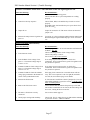
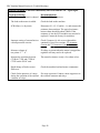
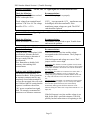
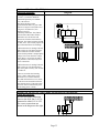
5.2 Pre Operation Voltage Checks
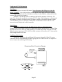
Never measure voltage test points when the motor is running.
Item
Measuring Location
3 Phase AC Input Power
Field AC Input Power
Single Phase Input Power
Signal Relay Power
Positive and Negative
Power Supplies
Voltage
AC Input Power Buss
(L1-L2-L3 or R,S,T)
Within !10% of Rated Voltage
Terminal Block (L1S, and L2S) (L1F and L2F)
Within !10% of Rated Voltage
110 VAC to 120 VAC
+19.5 VDC !1V
Terminal Block ( L1C and L2C)
Test Points on Regulator Card (+V to Com )
Test Points on Regulator Card
(+15 to Com ) (-15 to Com)
(+15 VDC !0.5V) (-15 VDC !0.5V)
5.3 Test Run
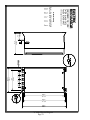
The primary adjustments have been made at the factory prior to shipping. The jumper settings
were covered in section 3 . Fine adjustments should be made in the following sequence prior to
full operation.
y
y
y
y
Confirm the operation of emergency stop sequence.
Set the JOG pot to an intermediate position.
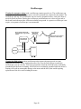
Start the motor using the jog control. If the motor rapidly accelerates past 20% of the motor’s
base speed. Stop and check if the tach feedback wires are connected properly and if the tach
voltage jumper is correct (see section 3.4). If the motor runs in the wrong direction, for
armature feedback check the polarity terminals F1, F2. For tach feedback check the polarity
of the tach wires to terminals 1 and 2.
When the motor operates properly, continue.
5.4 Jog Speed & Acceleration and Deceleration Adjustment
y Start the motor using the jog control.
Note: Jog operates only when the Run not activated.
y
y
y
Adjust the JOG pot until motor runs at desired speed.
Jog acceleration and deceleration time are adjusted by the “FT” pot. Clockwise is slower,
Counter Clockwise is faster. The scale of the FT pot is with in the range of the setting of the
DEC pot.
Note: Jog’s deceleration time is the same as Emergency Stop’s (E-Stop) deceleration time.
The user must decided witch function has priority when setting this adjustment. See section 5.5
Page 15