1
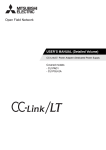
USER’S MANUAL (Detailed Volume)
FX2N-64CL-M CC-Link/LT Master Block
FX2N-64CL-M CC-Link/LT Master Block
Foreword
• This manual contains text, diagrams and explanations which will guide the reader in the
correct installation and operation of the FX 2N -64CL-M CC-Link/LT Master Block. This
Manual should be read and understood before attempting to install or use the unit.
• If the user is in any doubt at any stage of the installation of the FX2N-64CL-M CC-Link/LT
Master Block always consult a professional electrical engineer who is qualified and trained
to local and national standards that apply to the installation site.
• If the user is in any doubt about the operation or use of FX2N-64CL-M CC-Link/LT Master
Block please consult the nearest Mitsubishi Electric distributor.
• This manual is subject to change without notice.
FX2N-64CL-M CC-Link/LT Master Block
FX2N-64CL-M CC-Link/LT Master Block
USER’S MANUAL (Detailed Volume)
Manual number : JY997D08501
Manual revision : H
Date
: April 2015
i
FX2N-64CL-M CC-Link/LT Master Block
ii
FX2N-64CL-M CC-Link/LT Master Block
Safety guidelines for the User and Protection of the FX2N-64CL-M
This manual provides information for the use of the FX2N -64CL-M. The manual has been
written to be used by trained and competent personnel. The definition of such a person or
persons is as follows;
a) Any engineer who is responsible for the planning, design and construction of automatic
equipment using the product associated with this manual should be of a competent
nature, trained and qualified to the local and national standards required to fulfill that
role. These engineers should be fully aware of all aspects of safety with regards to
automated equipment.
b) Any commissioning or service engineer must be of a competent nature, trained and
qualified to the local and national standards required to fulfill that job. These engineers
should also be trained in the use and maintenance of the completed product. This
includes being completely familiar with all associated documentation for the said product.
All maintenance should be carried out in accordance with established safety practices.
c) All operators of the completed equipment (see Note) should be trained to use that
product in a safe manner in compliance to established safety practices. The operators
should also be familiar with documentation which is associated with the operation of the
completed equipment.
Note : The term ‘completed equipment’ refers to a third party constructed device which
contains or uses the product associated with this manual.
Notes on the Symbols Used in this Manual
At various times throughout out this manual certain symbols will be used to highlight points of
information which are intended to ensure the users personal safety and protect the integrity of
equipment. Whenever any of the following symbols are encountered its associated note must
be read and understood. Each of the symbols used will now be listed with a brief description of
its meaning.
Hardware Warnings
1) Indicates that the identified danger WILL cause physical and property damage.
2) Indicates that the identified danger could POSSIBLY cause physical and property
damage.
3) Indicates a point of further interest or further explanation.
Software Warnings
4) Indicates special care must be taken when using this element of software.
5) Indicates a special point which the user of the associate software element should
be aware of.
6) Indicates a point of interest or further explanation.
iii
FX2N-64CL-M CC-Link/LT Master Block
• Under no circumstances will Mitsubishi Electric be liable or responsible for any
consequential damage that may arise as a result of the installation or use of this equipment.
• All examples and diagrams shown in this manual are intended only as an aid to
understanding the text, not to guarantee operation. Mitsubishi Electric will accept no
responsibility for actual use of the product based on these illustrative examples.
• Please contact a Mitsubishi distributor for more information concerning applications in life
critical situations or high reliability.
iv
FX2N-64CL-M CC-Link/LT Master Block
Table of Contents
Guideline of Safty................................................................................ iii
Table of Contents .............................................................................. v
List of Manuals .........................................................................................1
Generic Names and Abbreviations...........................................................2
1. Outline ...................................................................................................1-1
1.1 Product Outline .................................................................................................... 1-1
1.2 Features .............................................................................................................. 1-1
1.3 Name and assignment of each part .................................................................... 1-2
2. Specifications ........................................................................................2-1
2.1
2.2
2.3
2.4
2.5
2.6
General specifications ......................................................................................... 2-2
Network wiring specifications .............................................................................. 2-2
Cable specifications............................................................................................. 2-3
Performance specifications ................................................................................. 2-4
Outside Dimensions ............................................................................................ 2-5
Compliance with EC directive .............................................................................. 2-6
3. System Startup Procedure ....................................................................3-1
4. System Configuration ............................................................................4-1
4.1 Total configuration ............................................................................................... 4-1
4.2 PLC connection ................................................................................................... 4-3
4.2.1 Applicable PLC and number of connectable FX2N-64CL-M ...................................... 4-3
4.3 Installation concept and condition of power adapter or dedicated power supply .... 4-4
4.3.1
4.3.2
4.3.3
4.3.4
Power adapter installation concept ........................................................................... 4-4
Power adapter installation condition.......................................................................... 4-4
Dedicated power supply installation concept ............................................................ 4-5
Dedicated power supply installation condition........................................................... 4-5
4.4 Selection of connection cables, connectors and terminal resistors ..................... 4-6
4.4.1 Selection of cables .................................................................................................... 4-6
4.4.2 Selection of connectors ............................................................................................. 4-6
4.4.3 Selection of terminal resistors ................................................................................... 4-6
4.5 Combination and mixed use of cables................................................................. 4-7
4.5.1 Combination of trunk line cable and drop line cables ................................................ 4-7
4.5.2 When using different cables together ........................................................................ 4-7
4.5.3 System configuration examples ................................................................................ 4-8
5. Handling Cautions .................................................................................5-1
5.1 Installation ........................................................................................................... 5-2
5.1.1 Installation direction................................................................................................... 5-2
5.1.2 DIN rail installation .................................................................................................... 5-2
5.1.3 Direct installation ....................................................................................................... 5-2
v
FX2N-64CL-M CC-Link/LT Master Block
6. Connection of Cables, Connectors and Terminating Resistors.............6-1
6.1 Connection cable/connector/terminal resistor connection procedure .................. 6-1
6.2 Connection of units using connection cables to CC-Link/LT
(in case of dedicated flat cable) ........................................................................... 6-2
6.3 How to attach connectors used for dedicated flat cable
(terminal/T-branch processing)............................................................................ 6-2
6.4 How to attach connectors used VCTF cable/high flexible cable
(terminal/T-branch processing)............................................................................ 6-4
6.5 How to attach terminating resistor ....................................................................... 6-8
6.6 Wiring check ........................................................................................................ 6-9
7. Various Modes ......................................................................................7-1
7.1 ONLINE mode (DIP switch bit 6 = OFF, bit 7 = OFF).......................................... 7-1
7.2 CONFIG mode (DIP switch bit 6 = ON, bit 7 = OFF) ........................................... 7-1
7.3 TEST mode (self-loop-back test) (DIP switch bit 6 = OFF, bit 7 = ON) ............... 7-1
8. Assignment of I/O numbers ...................................................................8-1
8.1 Relationship between I/O number and point mode ............................................. 8-1
8.2 Example of I/O number assignment .................................................................... 8-2
8.3 Automatic I/O numbers assignment .................................................................... 8-3
8.3.1 Automatic I/O numbers assignment procedure ......................................................... 8-3
8.3.2 Cautions on I/O number assignment when remote device stations are used ........... 8-4
8.4 Specification of reserved station.......................................................................... 8-5
8.4.1 Reserved station setting method ............................................................................... 8-5
8.5 Editing the detailed remote station information ................................................... 8-7
8.5.1 How to edit detailed remote station information ........................................................ 8-7
9. Data Link Processing Time ...................................................................9-1
9.1 Link scan time...................................................................................................... 9-1
9.1.1 Link scan time calculation formula ............................................................................ 9-1
9.1.2 Transmission delay time............................................................................................ 9-2
10.Assignment of Buffer Memory ............................................................10-1
10.1 Buffer memory list.............................................................................................. 10-1
10.2 Details of buffer memory ................................................................................... 10-3
10.2.1 Remote station connection information [BFM #0 (0h) to #3 (3h)]............................ 10-3
10.2.2 Link error station information [BFM #4 (4h) to #7 (7h)]............................................ 10-3
10.2.3 Remote I/O error information [BFM #8 (8h) to #11 (Bh)] ......................................... 10-5
10.2.4 Reserved station information [BFM #16 (10h) to #19 (13h)] ................................... 10-5
10.2.5 Number of required input blocks [BFM #20 (14h)]................................................... 10-6
10.2.6 Number of required output blocks [BFM #21 (15h)] ................................................ 10-6
10.2.7 Data link final station information [BFM #22 (16h)].................................................. 10-6
10.2.8 External switch information [BFM #26 (1Ah)] .......................................................... 10-6
10.2.9 Command [BFM #27 (1Bh)] .................................................................................... 10-7
10.2.10Status information [BFM #28 (1Ch)] ....................................................................... 10-8
10.2.11Detailed error information [BFM #29 (1Dh)]............................................................ 10-9
10.2.12Model code [BFM #30 (1Eh)]................................................................................ 10-11
10.2.13Detailed remote station information [BFM #32 (20h) to #95 (5Fh)] ...................... 10-11
10.2.14Remote device station input (output) data area
[BFM #144 (90h) to #159 (9Fh) and #208 (D0h) to #223 (DFh)]........................... 10-13
vi
FX2N-64CL-M CC-Link/LT Master Block
11.Program Example...............................................................................11-1
11.1
11.2
11.3
11.4
System Startup Procedure ................................................................................ 11-3
System configuration ......................................................................................... 11-4
Device assignment ............................................................................................ 11-5
Program example .............................................................................................. 11-6
12.Troubleshooting..................................................................................12-1
12.1 Status of each station during abnormal operation ............................................. 12-1
12.2 Confirmation of status based on status indicator LEDs and countermeasures.... 12-2
12.2.1 ONLINE mode ......................................................................................................... 12-2
12.2.2 CONFIG mode ........................................................................................................ 12-3
12.2.3 TEST mode (self-loop-back test)............................................................................. 12-4
12.3 Countermeasures based on detailed error information ..................................... 12-5
12.4 Self-loop-back test ............................................................................................. 12-7
12.4.1 Operating procedure ............................................................................................... 12-7
12.5 Prevention of erroneous inputs to and outputs from remote I/O module ........... 12-9
12.6 When using high flexible cable ........................................................................ 12-10
Warranty........................................................................................................ i
Revision History ........................................................................................... ii
vii
FX2N-64CL-M CC-Link/LT Master Block
MEMO
viii
List of Manuals
FX2N-64CL-M CC-Link/LT Master Block
List of Manuals
For manuals related to the FX2N-64CL-M, refer to each manual.
When other manuals and data are required, contact the dealer you purchased the product.
Manual title
Manual
number
Contents
Model name
code
FX1N Hardware Manual
Items related to the hardware including
JY992D89301 the I/O specifications, wiring and
installation of the PLC main unit
09R511
FX2N Hardware Manual
Items related to the hardware including
JY992D66301 the I/O specifications, wiring and
installation of the PLC main unit
09R508
FX2NC Hardware Manual
Items related to the hardware including
JY992D76401 the I/O specifications, wiring and
installation of the PLC main unit
09R509
FX3G Series User's Manual
- Hardware Edition
Detailed items related to the hardware
including the I/O specifications, wiring,
JY997D31301
installation and maintenance of the FX3G
Series PLC main unit
09R521
Detailed items related to the hardware
FX3GC Series User's Manual
including the I/O specifications, wiring,
JY997D45401
- Hardware Edition
installation and maintenance of the
FX3GC Series PLC main unit
09R533
FX3U Series User's Manual
- Hardware Edition
Detailed items related to the hardware
including the I/O specifications, wiring,
JY997D16501
installation and maintenance of the FX3U
Series PLC main unit
09R516
FX3UC Series User's
Manual - Hardware Edition
Detailed items related to the hardware
including the I/O specifications, wiring,
JY997D28701
installation and maintenance of the
FX3UC Series PLC main unit
09R519
FX3S/FX3G/FX3GC/FX3U/
FX3UC Series
Programming Manual
- Basic & Applied
Instruction Edition
Details of sequence programming for
FX3S/FX3G/FX3GC/FX3U/FX3UC Series,
JY997D16601 including explanation for basic
instructions, applied instructions and
various devices
09R517
CC-Link/LT : Power
Adapter•Dedicated Power
Supply USER'S MANUAL
(Detailed Volume)
Specifications, installation, power supply
wiring, cautions on construction, etc. of
JY997D06601
the power adapter CL1PAD1 and
dedicated power supply CL1PSU-2A
09R712
Remote I/O Remote device
For remote I/O stations and remote device stations for
CC-Link/LT, refer to each manual and related data.
−
1
FX2N-64CL-M CC-Link/LT Master Block
Generic Names and Abbreviations
Generic Names and Abbreviations
The generic names and abbreviations shown below are used within explanation contained in
this manual.
Generic name/abbreviation
Description
FX2N-64CL-M
CC-Link/LT Master block FX2N-64CL-M
Master station
Station which controls the data link system.
One master station is required in one system.
Remote I/O station
A remote station for bit information only
(for external device I/O).
Remote device station
Remote station that handles bit unit and word unit data only.
RD station
Abbreviation of remote device station
Remote station
Generic name for remote I/O station and remote device station.
Controlled by the master station.
Remote module
Generic name for remote I/O module and remote device module.
Power adapter
Unit connected to supply the power to the CC-Link/LT system
At least one power adapter or dedicated power supply is required in
each CC-Link/LT system.
Dedicated power supply
Connection cable
Generic name of dedicated flat cable, VCTF cable and high flexible
cable
Connector
Generic name of dedicated flat cable connector, VCTF cable connector and high flexible cable connector
2
Outline 1
FX2N-64CL-M CC-Link/LT Master Block
1.
Outline
1.1
Product Outline
The CC-Link/LT master block FX2N-64CL-M can be connected to the FX Series PLC.
The CC-Link/LT system can be constructed with an FX Series PLC as the master station.
1.2
Features
The FX2N-64CL-M has the following features:
1) Reduced wiring time
Using CC-Link/LT connection cables and connectors allow for reduced wiring times.
(Dedicated flat cables, VCTF cables and high flexible cables are available.)
2) Simplified programs
Link devices within CC-Link/LT are assigned to X/Y devices in the PLC, therefore, sequence
programs can be prepared without recognizing the network.
3) High speed refresh
High speed refresh (128 points/0.3 ms) is realized (as and when the transmission speed is
2.5 Mbps, 16-point mode is selected and eight stations are connected to the network).
4) Slave station disconnection function
Even if some units are down due to an abnormality, communication with the remaining
functional units is not affected.
When a cable in the trunk line is disconnected, however, the data link is disabled for remote
stations connected to the disconnected cable.
5) Automatic return function
When a unit that was disconnected due to an abnormality is restored to it’s normal status,
the unit will return to the data link automatically and continue data transfer.
6) Data link stop/re-start
While data link is being executed, the user can stop and start the link again.
7) Remote station type information storage
In the CONFIG mode, the number of points occupied by remote stations, I/O types, etc. is
detected, and stored within the EEPROM.
8) Mode selection
The ONLINE, CONFIG and TEST modes are available.
ONLINE mode : Executes the data link for the CC-Link/LT system.
Select the ONLINE mode usually.
CONFIG mode: Allows automatic assignment of the I/O number.
When remote stations are planned to be added in the future, reserved
stations can be specified and detailed remote station information can be
edited.
After constructing the CC-Link/LT system, make sure to execute the
CONFIG mode once to assign the I/O number.
TEST mode : Executes self-diagnosis to judge whether the FX2N-64CL-M itself is in the
master station.
If the data link cannot be executed normally, the self-diagnosis function
analyses the FX2N-64CL-M itself.
1-1
FX2N-64CL-M CC-Link/LT Master Block
Name and assignment of each part
Name
POWER
Status indicator LEDs
1.3
Outline 1
RUN
Description
<ONLINE mode/CONFIG mode/TEST mode>
Lit
:Power is supplied
Extinguished :Power is not supplied
<ONLINE mode>
Lit
:FX2N-64CL-M is operating normally
Extinguished :FX2N-64CL-M is abnormal
Power is interrupted
EEPROM read error (sum mismatch) occurred
<CONFIG mode>
Lit
:FX2N-64CL-M is operating normally
Extinguished :FX2N-64CL-M is abnormal
Power is interrupted
<TEST mode>
Lit
:FX2N-64CL-M is operating normally
Extinguished :FX2N-64CL-M is abnormal
Power is interrupted
1-2
FX2N-64CL-M CC-Link/LT Master Block
Name
Status indicator LEDs
ERR.
L RUN
L ERR.
SD
RD
Interface
Outline 1
Description
<ONLINE mode>
Lit
:Communication speed setting error occurred
EEPROM read error (sum mismatch) occurred
Flickering
:Power supplied for communication is abnormal
DIP switch for operation setting was changed during
operation
Extinguished :FX2N-64CL-M is operating normally
<CONFIG mode>
Lit
:Communication speed setting error occurred
EEPROM write error occurred
Flickering
:Power supplied for communication is abnormal
DIP switch for operation setting was changed during
operation
Extinguished :FX2N-64CL-M is operating normally
<TEST mode>
Lit
:Communication speed setting error occurred
Flickering
:Power supplied for communication is abnormal
DIP switch for operation setting was changed during
operation
Extinguished :FX2N-64CL-M is operating normally
<ONLINE mode/CONFIG mode>
Lit
:Data link is executed
Extinguished :Data link is stopped
<TEST mode>
Lit
:Self-loop back Test was finished normally
Extinguished :Self-loop back Test was finished abnormally
(Extinguished while the self-loop back Test is executed)
<ONLINE mode>
Lit
:Use station number discrepancy
Outside-control-range station error occurred
Flickering
:Stations are abnormal
Extinguished :Data link is executed normally
<CONFIG mode>
Lit
:Use station number discrepancy
(when BFM#32(20h) to #95(5Fh) is edited, the station
numbers are checked.)
(When the power is turned ON while a remote station is
attached and the following setting is made: number of
connected stations varies by editing BFM#32(20h) to
#95(5Fh))
Flickering
:All stations are abnormal
(when BFM#32(20h) to #95(5Fh) is edited, the station
numbers are checked.)
(When power is turned ON while no remote station is
attached and then BFM#32(20h) to #95(5Fh) is edited)
Extinguished :Data link is executed normally
<TEST mode>
Lit
:Self-loop back Test was finished abnormally
Extinguished :Self-loop back Test was finished normally
(Extinguished while the self-loop back Test is executed)
<ONLINE mode/CONFIG mode/TEST mode>
Lit: Data is currently being sent
<ONLINE mode/CONFIG mode/TEST mode>
Lit: Data is currently being received
Connector for CC-Link/LT interface (24G/DB/DA/+24 V)
1-3
FX2N-64CL-M CC-Link/LT Master Block
Outline 1
Name
Description
Communication speed setting
1
Communication speed
DIP switch for operation setting
B RATE
2
SW1
SW2
156 kbps
OFF
OFF
625 kbps
ON
OFF
2.5 Mbps
OFF
ON
Setting disabled
ON
ON
Point mode setting
(Select the number of I/O points per station.)
3 16pts/4pts
OFF:4-point mode (4 input points and 4 output points in each station)
ON :16-point mode (16 input points and 16 output points in each station)
4
-Setting is disabled. (Make sure that it is OFF during operation.)
5
-Setting is disabled. (Make sure that it is OFF during operation.)
CONFIG mode
OFF: ONLINE mode (normal operation)
6 CONFIG/ONLINE
ON : CONFIG mode (The information on the connected stations is saved to
the EEPROM.)
TEST mode
7 TEST/ONLINE
OFF: ONLINE mode (normal operation)
ON : TEST mode (Self-loop back Test)
8
-Setting is disabled. (Make sure that it is OFF during operation.)
• Factory default, DIP switches are set OFF.
• The Test mode is selected when both the CONFIG and TEST modes are set ON
simultaneously.
• For each setting, the status at the time of power ON is valid.
(If a setting is changed after the power is set ON, such a change is invalid.)
• In the CONFIG mode, the L ERR. indicator lights or flickers when the detailed information
on the remote station actually connected at the time of power ON do not match the detailed
remote station information within the master.
(When BFM #32 (20h) to #95 (5Fh) are edited, the station numbers are checked.)
If the remote station information is not edited, the L ERR. does not light or flicker when
turning ON the all disconnected remote station, or when removing the remote station after
power ON.
1-4
FX2N-64CL-M CC-Link/LT Master Block
Outline 1
Note: Setting DIP switches component change
Products manufactured in March 2012 or later have a different component used for the setting DIP switches compared with products produced earlier.
Due to the component change, take note of the change in the ON/OFF position of each DIP
switch.
Even with the component change, the direction for setting each DIP switch ON/OFF is the
same.
1-5
FX2N-64CL-M CC-Link/LT Master Block
Outline 1
MEMO
1-6
FX2N-64CL-M CC-Link/LT Master Block
2.
Specifications 2
Specifications
This section explains the specifications of the FX2N-64CL-M.
DESIGN PRECAUTIONS
When a remote module fails, outputs may randomly set ON or OFF, therefore, build an
external monitoring circuit that will monitor any input signals that could cause a serious
accident.
DESIGN PRECAUTIONS
• Do not bind control and connection cables to CC-Link/LT together with power cables.
Keep control and connection cables to CC-Link/LT away from major circuits and power
cables by 100 mm (3.93") or more.
It may cause a malfunction due to noise interference.
• Use the FX2N-64CL-M in such status that any force is not applied on connectors for CCLink/LT interface and connection cables to CC-Link/LT.
If any force is applied, wire breakage and failure may be caused.
STARTING AND MAINTENANCE PRECAUTIONS
• Do not touch the terminals while the power is ON. It may cause an electric shock or
malfunction.
• Shut down all phases of the power supply outside the master block before starting any
cleaning procedures.
If the power is not disconnected from all sources, the FX 2N -64CL-M may fail or
malfunction.
STARTING AND MAINTENANCE PRECAUTIONS
• Do not disassemble or modify the FX2N-64CL-M.
Doing so may cause failure, malfunction, injury, or fire.
• The case of the FX2N-64CL-M is made of resin.
Do not drop or apply strong impacts to the FX2N-64CL-M.
DISPOSAL PRECAUTIONS
• Treat the FX2N-64CL-M as industrial waste when disposing of the product.
2-1
FX2N-64CL-M CC-Link/LT Master Block
2.1
Specifications 2
General specifications
The general specifications except the following are the same as the PLC main unit. (For the
general specifications except the following, refer to the PLC main unit manual.)
Item
Specification
Dielectric withstand
voltage
500V AC for 1 min
Isolation resistance
5 MΩ or more by 500V DC
megger
2.2
Between case and PLC grounding terminal
Network wiring specifications
Item
Communication speed
Specification
2.5Mbps
Distance between stations
Maximum number of
modules connected in 1
drop line
Maximum trunk length
35m (114' 9")
T-branch interval
625kbps
Remarks
156kbps
--
No restriction
--
8 units
Maximum number of
remote modules
connected per branch in
a drop line
100m (328' 1")
500m (1640' 5")
No restriction
Cable length between
terminating resistors
--
Maximum drop length
4m (13' 1")
16m (52' 5")
60m (196' 10")
Cable length per branch
Cumulative drop line
length
15m (49' 2")
50m (164' 0")
200m (656' 2")
Sum of all drop lines
2-2
FX2N-64CL-M CC-Link/LT Master Block
2.3
Specifications 2
Cable specifications
Dedicated flat cables, VCTF cables and high flexible cables are available.
1) Dedicated flat cable
Type
Service
temperature
range
Rated
voltage
Number
of cores
Conductor
resistance
(at 20°C)
Flat cable
-10 to 80 °C
30V
4
23.4 Ω/km
or less
Safety
Flame
resistance
UL Subject758 UL VW-1 • -F-
2) VCTF cable specifications (Extract from JIS C 3306)
Conductor
Type
Number
of cores
Vinyl cabtyre,
Round cord
4
Conductor
Nominal Number of
Insulator
Sheath
crosselement
Outside thickness thickness resistance
(at 20°C)
sectional wires/Wire diameter
area
diameter
0.75mm2
30/0.18mm
1.1mm
0.6mm
1.0mm
25.1Ω/km
3) High flexible cable
Use the following high flexible cables certified by the CC-Link Association.
Manufacturer name
Cable model name
DAIDEN Co., Ltd.
CM/LT(2586) AWG19/4C
Yoshinogawa Electric Wire & Cable Co.,Ltd
CRFV-A075C04-LT
Kuramo Electric Co., Ltd.
FANC-Z/LT 4×0.75mm2
Mitsubishi Electric System & Service Co.Ltd
CL9-MV4-075
2-3
FX2N-64CL-M CC-Link/LT Master Block
2.4
Specifications 2
Performance specifications
Item
Applicable PLC
Specification
FX1N/FX2N/FX2NC/FX3G/FX3GC/FX3U*1/FX3UC*1 Series PLC
(FX2NC-CNV-IF is required when FX2NC Series PLC is connected.)
(FX2NC-CNV-IF or FX3UC-1PS-5V is required when FX3GC/FX3UC Series
PLC is connected.)
FX1N Series: Up to 4 *2
FX2N Series: Up to 8 *3
*3
FX2NC Series: Up to 3
FX3G/FX3U Series: Up to 8 *3
*3
FX3GC/FX3UC Series: Up to 5
Applicable point mode
4-point mode and 16-point mode (selectable by DIP switch)
4-point mode
16-point mode
Connected to FX1N/FX3G/FX3GC Series PLC: 128 points
Connected to FX2N/FX2NC/FX3U/FX3UC Series PLC: 256 points
Maximum number of link points
(including the number of I/O points in each PLC) (For the number of I/O
points in each PLC, refer to the manual of the PLC main unit.)
Number of link points per station
( ) shows the number of link
4 points (8 points)
16 points (32 points)
points when composite remote
module is used.
Points
128 points
256 points
2.5Mbps
0.7ms
1.0ms
32 stations
625kbps
2.2ms
3.8ms
156kbps
8.0ms
14.1ms
Points
256 points
256 points
2.5Mbps
1.2ms
2.0ms
64 stations
625kbps
4.3ms
7.4ms
156kbps
15.6ms
27.8ms
Communication speed
2.5 Mbps, 625 kbps and 156 kbps (selectable by DIP switch)
Protocol
BITR method (Broadcastpolling + Interval Timed Response)
Network topology
T-branch
Error control method
CRC
Number of connected stations
64 stations maximum
Remote station numbers
1 to 64
Master station connection
Connected at end of trunk line
position
Communication error detection, automatic return to system, slave station
RAS function
disconnection and internal loop back diagnosis
Communication specifications
Control specifications
Link scan time
Number of connectable master
blocks
Dedicated flat cable (0.75 mm2 × 4)
Connection cable
VCTF cable (0.75 mm2 × 4 cable specifications, refer to Section 2.3)
High flexible cable (0.75 mm2 × 4)
Number of occupied I/O points
8 points (fixed) + Number of connected remote I/O points (in multiples of eight)
Current consumption inside 5V DC 190 mA (Supplied by PLC via extension connector)
Voltage
20.4V to 28.8V DC
Supplied from power adapter or
24V DC power
Current
25 mA
dedicated power supply via
supply
consumption
connector.
Initial current
35 mA
Mass (weight)
0.15 kg (0.33 lbs)
*1 FX3U/FX3UC Series PLC can use direct specification of buffer memory.
Refer to the FX3S/FX3G/FX3GC/FX3U/FX3UC Series Programming Manual - Basic & Applied Instruction Edition
for details.
2-4
FX2N-64CL-M CC-Link/LT Master Block
Specifications 2
*2 When connected to an FX1N Series PLC, up to two FX2N-64CL-M can be connected to each of the main and
extension units.
*3 The FX2N-64CL-M draws 190mA from the 5V DC source.
The total 5V consumption of all special function blocks connected to the main unit or extension unit must not
exceed the 5V source capacity of the system.
(For details, refer to the manual of the PLC main unit.)
2.5
Outside Dimensions
2-5
FX2N-64CL-M CC-Link/LT Master Block
2.6
Specifications 2
Compliance with EC directive
This note does not guarantee that an entire mechanical module produced in accordance with
the contents of this note will comply with the following standards.
Compliance to EMC directive of the entire mechanical module should be checked by the user /
manufacturer.
Attention
• This product is designed for use in industrial applications.
Note
• Authorized Representative in the European Community:
Mitsubishi Electric Europe B.V.
Gothaer Str. 8, 40880 Ratingen, Germany
Requirement for Compliance with EMC directive
This products have shown compliance through direct testing (of the identified standards below)
and design analysis (through the creation of a technical construction file) to the European
Directive for Electromagnetic Compatibility (2004/108/EC) when used as directed by the
appropriate documentation.
Type
: Programmable Controller (Open Type Equipment)
Models : Products manufactured from February 1st, 2003
EN61000-6-4: 2007
EN61131-2:2007
Standard
Generic emission standard
Industrial environment
Remark
Compliance with all relevant aspects
of the standard.
• Emission-Enclosure port
• Emission-Low voltage AC mains
port
• Emission-Telecommunications/
network port
Programmable controllers
Compliance with all relevant aspects
- Equipment requirements and tests of the standard.
EMI
• Radiated Emissions
• Conducted Emissions
EMS
• Radiated electromagnetic field
• Fast Transient burst
• Electrostatic discharge
• High-energy surge
• Voltage drops and interruptions
• Conducted RF
• Power frequency magnetic field
2-6
FX2N-64CL-M CC-Link/LT Master Block
Specifications 2
Notes for compliance to EMC regulation
• It is necessary to install the FX2N-64CL-M in a shielded metal control panel.
For more details please contact the local Mitsubishi Electric sales site.
• Use the CC-Link/LT module in Zone A*1 as defined in EN61131-2.
The terminal and the wiring for the following table can be used in zone B*1.
Classification
Model
Terminal that can be used in
zone B
Rated load
voltage
Relay output*2
CL1Y4-R1B1
CL1Y4-R1B2
Terminal to connect output signals
and load power supply.
240V AC or less*3
30V DC or less
CL1XY4-DR1B2 Terminal to connect output signals
CL1XY8-DR1B2
and load power supply.
240V AC or less*3
30V DC or less
Terminal block to connect power
supply.
100/120/200/230/
240V AC
DC input/
Relay output*2
CC-Link/LT
Dedicated Power
Supply
CL1PSU-2A
*1 Zone defined in EN61131-2
Separation defined in EN61131-2 for EMC LVD regulation decided depending on
condition in industrial setting.
Zone C = Factory mains which is isolated from public mains by dedicated transformers.
Zone B = Dedicated power distribution which is protected by secondary surge
protection. (300V or less in the rated voltage is assumed.)
Zone A = Local power distribution which is isolated from dedicated power distribution by
AC/DC converters, isolation transformers, etc. (120V or less in the rated
voltage is assumed.)
*2 Terminal block connection type.
*3 250V AC or less when the unit does not comply with UL or cUL standards.
• When the following models use the CC-Link/LT power adapter model (CL1PAD1), a power
line connecting to the external power supply terminal of the CL1PAD1 must be 30m (98’5”)
or less.
Classification
CL2AD4-B
Converter*4
CL2DA2-B
Analog-Digital Converter
Digital-Analog
Model
*4
*4 Terminal block connection type.
2-7
FX2N-64CL-M CC-Link/LT Master Block
Specifications 2
MEMO
2-8
System Startup Procedure 3
FX2N-64CL-M CC-Link/LT Master Block
3.
System Startup Procedure
Start up the CC-Link/LT system using the following procedure.
Start
Install the FX2N-64CL-M, remote modules and power adapter / dedicated power supply to the control panel and machine.
Connect the FX2N-64CL-M, remote modules and power adapter / dedicated power supply with
cables, and connect terminal resistors at the ends of the trunk line.
Set the transmission speed, point mode, station number, etc. of the FX2N-64CL-M and remote
modules using the DIP switches. (Set the FX2N-64CL-M to the CONFIG mode.)
Refer to
Section 5.
Refer to
Section 6.
Refer to
Sections 1
and 7.
Check the following items before turning the power ON.
- Confirm the installation status of the FX2N-64CL-M, remote modules and power adapter / dedicated power supply.
- Confirm the supply voltage input to the power adapter or dedicated power supply.
- Confirm that the RUN/STOP switch for the main unit is set to STOP.
- Confirm that the same station number is not used in two or more remote modules.
Executing CONFIG mode
Turn ON the power to the power adapter or dedicated power supply, and then turn ON the power to the main unit.
(Specify reserved stations and edit the detailed remote station information here if necessary.)
Refer to
Section 8.
Terminating CONFIG mode
Turn OFF the power to the power adapter or dedicated power supply, and then turn OFF the power to the main unit.
Set the DIP switch in the FX2N-64CL-M to the ONLINE mode.
Turn ON the power to the power adapter or dedicated power supply, and then turn ON the power to the main unit.
Confirming the operation based upon LEDs
FX2N-64CL-M
- Data link is normal: L RUN is lit.
- Data link is abnormal: L ERR. is lit or flickering.
- Setting is abnormal: The ERR. is lit.
Remote module
- Confirm remote station connection by checking buffer memory [BFM #0 (0h) to #3 (3h)] in the
FX2N-64CL-M.
- Confirm device operation using peripheral equipment for the PLC (with regard to monitorly and
forcing inputs + outputs ON and OFF).
Write a control program to the main unit.
Refer to
Sections 10
and 12.
Refer to
Section 11.
Operate the system.
End
3-1
FX2N-64CL-M CC-Link/LT Master Block
System Startup Procedure 3
MEMO
3-2
System Configuration 4
FX2N-64CL-M CC-Link/LT Master Block
4.
System Configuration
This section explains the CC-Link/LT system configuration.
DESIGN PRECAUTIONS
When a remote module fails, outputs may randomly turn ON or OFF, therefore, build an
external monitoring circuit that will protect from any input signals that could cause a serious
accident.
DESIGN PRECAUTIONS
• Do not bind control cables and connection cables to CC-Link/LT together with power
cables.
Keep control cables and connection cables to CC-Link/LT away from major circuits and
power cables by 100 mm (3.93") or more.
It may cause a malfunction due to noise interference.
• Use the FX2N-64CL-M in an environment status that any force is not directly applied on
connectors for CC-Link/LT interface and connection cables to CC-Link/LT.
If any force is applied, wire breakage and failure may occur.
4.1
Total configuration
This paragraph describes the system configuration and cautions for CC-Link/LT.
Trunk length (branch line length not included)
PLC main unit
200mm
(7.87")
or less
Terminating
resistor
T-branch
connection
Power adapter or
dedicated power
supply
Drop length*1
(including branch)
Remote
I/O station
Remote
I/O station
Distance between
stations
T-branch interval
Remote
device
station
Remote
I/O station
Remote
I/O station
Remote
I/O station
*0
Terminating
resistor
Trunk line
Drop line
*1 The maximum drop line length and total drop line length include the branch length from
the drop line.
4-1
FX2N-64CL-M CC-Link/LT Master Block
System Configuration 4
• Connect the master station, power adapter / dedicated power supply and remote stations
using cables and connectors. For the combination and mixed use of cables, refer to Section
4.5.
• The trunk line and drop line can be connected using connectors or terminal blocks. Terminal
blocks are available only when VCTF cables or high flexible cables are used.
• Make sure to install the FX2N-64CL-M at the end of the trunk line.
• Up to 64 remote stations can be connected to one FX2N-64CL-M as far as the condition
shown in the table below are satisfied.
Item
Communication speed
Distance between
stations
Maximum number of
modules connected in 1
drop line
Maximum trunk length
T-branch interval
Maximum drop length
Cumulative drop line
length
2.5Mbps
Specification
625kbps
156kbps
No restriction
Remarks
---
Maximum number of
remote modules connected
per branch in a drop line
Cable length between
35m (114' 9") 100m (328' 1") 500m (1640' 5")
terminating resistors
(excluding drop line length)
No restriction
-4m (13' 1")
16m (52' 5")
60m (196' 10")
Cable length per branch
8 units
15m (49' 2")
50m (164' 0")
200m (656' 2")
Sum of all drop lines
• The connection order of remote stations has no relevance to the station number.
Even if the station number of remote stations is not consecutive, no error will occur in the
data link.
• In the CC-Link/LT system, terminating resistors should be connected to both ends of the
trunk line.
Connect the terminating resistor on the FX2N-64CL-M side to a position within 200 mm
(7.87") from the FX2N-64CL-M.
• Equipment for CC-Link cannot be connected to the CC-Link/LT system.
On the contrary, equipment for CC-Link/LT cannot be connected to the CC-Link system.
• For the installation conditions of the power adapter, dedicated power supply and remote
module, refer to the instruction manual of each one. Install each of them correctly.
• Refer to the homepage of the CC-Link Partner Association (CLPA) "http://www.cc-link.org/" for
details concerning connection cabling, terminating resistors and connector for CC-Link/LT.
4-2
FX2N-64CL-M CC-Link/LT Master Block
4.2
System Configuration 4
PLC connection
This section explains which PLC series are connectable with the FX2N-64CL-M and gives
cautions on the number of connectable FX2N-64CL-M blocks.
4.2.1
Applicable PLC and number of connectable FX2N-64CL-M
Applicable PLC
FX1N/FX2N/FX2NC/FX3G/FX3GC/FX3U/FX3UC Series PLC
(FX2NC-CNV-IF is required when an FX2NC Series PLC is connected.)
(FX2NC-CNV-IF or FX3UC-1PS-5V is required when an FX3GC/FX3UC Series
PLC is connected.)
Number of connectable master blocks
FX1N Series: Up to 4
FX2N Series: Up to 8
FX2NC Series: Up to 3
FX3G/FX3U Series: Up to 8
FX3GC/FX3UC Series: Up to 5
• Connect the FX2N-64CL-M to the right side of the PLC using an extension cable.
• The number of occupied I/O points is "8 (either input or output) points + Number of
connected remote I/O points (in multiples of eight)".
The total number of I/O points including extended points must not exceed 128 points for the
FX1N, FX3G and FX3GC Series or 256 points for the FX2N, FX2NC, FX3U and FX3UC Series.
For the number available of I/O points of the connected PLC, refer to the manual of the PLC
main unit.
• The FX2N-64CL-M consumes 190 mA from the 5V DC source.
The total current consumption from the 5V source of special function blocks connected to
the PLC must not exceed the 5 V power capacity of the main unit and extension units.
When connecting to the FX 1N Series PLC, a maximum of two FX 2N -64CL-M can be
connected to the main and another two on the extension unit.
For details on connection to the PLC main unit, refer to the manual of the PLC main unit.
4-3
FX2N-64CL-M CC-Link/LT Master Block
4.3
System Configuration 4
Installation concept and condition of power adapter or dedicated power supply
At least one power adapter or dedicated power supply is required for each CC-Link/LT system.
4.3.1
Power adapter installation concept
When constructing a system using only one power adapter, the following three conditions
should be satisfied.
1) Total current consumption of remote modules, I/O equipment and the master block
receiving power from power adapter (including current consumption at startup) ≤ 5 A
2) To operate the system in a stable environment, the voltage drop* should be equivalent to or
less than 3.6V.
3) As the minimum operating voltage from the power adapter is 20.4V for each remote module,
Supply voltage to power adapter - Voltage drop* ≥ 20.4 V
If the total current consumption or voltage drop* is large, the power adapter position should be
changed or additional power adapters should be installed.
It is necessary to consider the maximum output voltage, rated output current and maximum
output current for the general-purpose power supply connected to the power adapter.
For details on the CL1PAD1 (power adapter), refer to the separate document "CC-Link/LT:
Power Adapter•Dedicated Power Supply USER'S MANUAL (Detailed Volume)".
When using another product, refer to the corresponding manual.
* Voltage drop from the power adapter to the master station and remote modules (when
operating temperature is 20°C)
4.3.2
Power adapter installation condition
The condition for installing the power adapter supplying the power to the CC-Link/LT varies
depending on the connected equipment and wiring length. For details on the condition for
installing the CL1PAD1 (power adapter), refer to the separate document "CC-Link/LT: Power
Adapter•Dedicated Power Supply USER'S MANUAL (Detailed Volume)".
When using another product, refer to the corresponding manual.
4-4
FX2N-64CL-M CC-Link/LT Master Block
4.3.3
System Configuration 4
Dedicated power supply installation concept
When constructing a system using only one dedicated power supply, the following three
conditions should be satisfied.
1) Total current consumption of remote modules, I/O equipment and master block receiving
power from dedicated power supply (including current consumption at startup) ≤ 2A
2) To operate the system in a stable environment, the voltage drop* should be equivalent to or
less than 3.6V.
3) As the minimum operating voltage from the dedicated power supply is 20.4V for each
remote module, Supply voltage to dedicated power supply - Voltage drop* ≥ 20.4 V
If the total current consumption or voltage drop* is large, the dedicated power supply position
should be changed or additional dedicated power supply should be installed.
For details on the CL1PSU-2A (dedicated power supply), refer to the separate document "CCLink/LT: Power Adapter•Dedicated Power Supply USER'S MANUAL (Detailed Volume)".
When using another product, refer to the corresponding manual.
* Voltage drop from the power adapter to the master station and remote modules (when
operating temperature is 20°C)
4.3.4
Dedicated power supply installation condition
The condition for installing the dedicated power supply supplying the power to the CC-Link/LT
varies depending on the connected equipment and wiring length. For details on the condition
for installing the CL1PSU-2A (dedicated power supply), refer to the separate document "CCLink/LT: Power Adapter•Dedicated Power Supply USER'S MANUAL (Detailed Volume)".
When using another product, refer to the corresponding manual.
4-5
FX2N-64CL-M CC-Link/LT Master Block
4.4
System Configuration 4
Selection of connection cables, connectors and terminal resistors
For the latest information on the connection cables, connectors and terminal resistors, refer to
the homepage of the CC-Link Association (http://www.cc-link.org/) or catalogs (issued by the
CC-Link Association).
4.4.1
Selection of cables
For details on selection of connection cables, refer to the homepage of the CC-Link
Association or CC-Link/LT catalogs.
Connection cable
Reference
Dedicated flat cable
VCTF cable
For specifications, refer to Section 2.3.
High flexible cable
4.4.2
Selection of connectors
The table below shows the specifications of the VCTF cable connector and high flexible cable
connector.
For details on selection of connectors, refer to the homepage of the CC-Link Association or
CC-Link/LT catalogs.
Connector
Model name (manufacturer name)
Dedicated flat cable
CL-9-CNF-18
connector
(Mitsubishi Electric System & Service Co.Ltd)
Cover
color*1
Cable insulator
outside diameter
Light blue
−
VCTF Cable
Connector
CL9-CNR-23
(Mitsubishi Electric System & Service Co.Ltd)
Green
φ2.1 to 2.4
High Flexible Cable
Connector
CL9-CNR-20
(Mitsubishi Electric System & Service Co.Ltd)
Yellowish
green
φ1.8 to 2.1
*1 The body color is light blue.
4.4.3
Selection of terminal resistors
Use the CL9-TERM (gray). When only dedicated flat cables are used in the system, the CL9RYVK (black) is also available.
Make sure to use the terminal resistors having the same model name at the both ends of the
trunk line.
For details on terminal resistors, refer to the homepage of the CC-Link Association or CC-Link/
LT catalogs.
4-6
FX2N-64CL-M CC-Link/LT Master Block
System Configuration 4
4.5
Combination and mixed use of cables
4.5.1
Combination of trunk line cable and drop line cables
The table below shows the combination of cables for the trunk line and drop line.
"Flat" indicates dedicated flat cable. "VCTF" indicates VCTF cable. "Flexible" indicates high
flexible cable. "/" indicates mixed use of cables in the drop line.
For example, "Flat/VCTF" indicates mixed use of dedicated flat cable and VCTF cable in the
drop line.
Drop line
Trunk line
No mixed use of cables in drop line
Flat
VCTF
Flexible
Mixed use of cables in drop line
Flat/
VCTF
Flat/
flexible
VCTF/ Flat/VCTF/
flexible
flexible
Dedicated flat cable
VCTF cable
High flexible cable
4.5.2
When using different cables together
1) Trunk line
Different cables are not available.
2) Drop line
a) Different cables are available.
b) Different cables are not available in one drop line. (Refer to the left side of the figure
below.)
In the case of unit having cable (such as CL1Y2-T1D2S), however, a different type of
cable can be connected only when the dedicated flat cable of the unit is 200mm (7.87")
or less. (Refer to the right side of the figure below.)
4-7
FX2N-64CL-M CC-Link/LT Master Block
4.5.3
System Configuration 4
System configuration examples
1) When the dedicated flat cable is used as the trunk line
*1 For the processing procedure of the VCTF cable connector (for connecting the terminal
resistor), refer to "6.4 How to attach connectors used for VCTF cable/high flexible cable".
*2 For the processing procedure of the dedicated flat cable connector (for connecting the
terminal resistor), refer to "6.3 How to attach connectors used for dedicated flat cable".
*3 The dedicated power supply is also available.
4-8
FX2N-64CL-M CC-Link/LT Master Block
System Configuration 4
2) When the VCTF cable is used as the trunk line
*1 For the processing procedure of the VCTF cable connector (for connecting the terminal
resistor), refer to "6.4 How to attach connectors used for VCTF cable/high flexible cable".
*2 For the processing procedure of the dedicated flat cable connector (for connecting the
terminal resistor), refer to "6.3 How to attach connectors used for dedicated flat cable".
*3 The dedicated power supply is also available.
4-9
FX2N-64CL-M CC-Link/LT Master Block
System Configuration 4
3) When the high flexible cable is used as the trunk line
*1 For the processing procedure of the VCTF cable connector (for connecting the terminal
resistor), refer to "6.4 How to attach connectors used for VCTF cable/high flexible cable".
*2 For the processing procedure of the dedicated flat cable connector (for connecting the
terminal resistor), refer to "6.3 How to attach connectors used for dedicated flat cable".
*3 A dedicated power supply is also available.
4-10
FX2N-64CL-M CC-Link/LT Master Block
5.
Handling Cautions 5
Handling Cautions
INSTALLATION PRECAUTIONS
• Use the FX2N-64CL-M in an environment with the general specifications described in this
manual.
Never use the product in areas with excessive dust, oily smoke, conductive dusts,
corrosive gas (salt air, Cl2, H2S, SO2 or NO2), flammable gas, vibration or impacts, or
expose it to high temperature, condensation, or rain and wind.
• Do not directly touch the conductive area of the FX2N-64CL-M, otherwise, the
FX2N-64CL-M may malfunction or fail.
• Shut down all phases of the power supplies before attaching/removing the FX2N-64CL-M
to/from the panel, otherwise, the FX2N-64CL-M may fail or malfunction.
• Securely fix the FX2N-64CL-M with DIN rail or mounting screws. When using mounting
screws, securely tighten them within the specified torque range.
(Refer to Subsection 5.1.3)
If the screws are too loose, the module may detach from its installed position, short
circuit, or malfunction. If the screws are too tight, the screws may be damaged, which
may cause the module to detach from its installed position or short circuit.
• Install the FX2N-64CL-M on to a flat surface.
If the installation surface is not flat, an excessive force may be applied on the PCBs,
leading to nonconformity.
5-1
FX2N-64CL-M CC-Link/LT Master Block
5.1
Handling Cautions 5
Installation
The FX2N-64CL-M can be attached via DIN rail or attached directly with screws.
The installation procedure in each case is described below.
5.1.1
Installation direction
• Do not install the master block on floor surfaces, ceiling surfaces or in a horizontal direction.
If the master block is installed in such a way, its temperature may rise.
Install the master block vertically on wall surfaces as shown in the figure below.
• Secure a space of 50 mm (1.96") or more between the master block and other equipment or
structures. Keep the master block off high voltage cables, high voltage equipment and
power equipment as much as possible.
5.1.2
DIN rail installation
Align the upper DIN rail installation groove in the module with the DIN rail 1), and press the
module in that position 2).
When removing the module, pull the installation hook downwards 3), then remove the module
4).
Applicable DIN rail
5.1.3
TH35-7.5Fe and TH35-7.5AI
Direct installation
Fix the FX2N-64CL-M on to the panel surface by tightening M4 screws inserted in two (upper
and lower) mounting holes provided on the master block.
Install the FX2N-64CL-M and other units so that a clearance of 1 to 2 mm is assured among
each unit.
Applicable screw
M4 height: 16mm(0.63") or more (Tightening torque range: 0.78 to 1.08 N⋅m)
5-2
FX2N-64CL-M CC-Link/LT Master Block
6.
Connection of Cables, Connectors and Terminating Resistors 6
Connection of Cables, Connectors and Terminating Resistors
Connect the master station, power adapter / dedicated power supply and remote stations with
connection cables and connectors.
It is necessary to connect terminal resistors at the both ends of the trunk line in the CC-Link/LT
system.
WIRING PRECAUTIONS
• Shut down all phases of the power supplies before starting installation or wiring work.
If the power is not disconnected from all sources an electric shock or serious product
damage may occur.
WIRING PRECAUTIONS
• Correctly wire the master block while confirming the rated voltage and terminal
arrangement of the FX2N-64CL-M.
If a power supply different from the rated supply is connected or wiring is performed
incorrectly, fire or failure may be caused.
• Pay attention to foreign objects such as cuttings or wiring chips do not enter the
FX2N-64CL-M, otherwise, fire, product failure or malfunction may occur.
6.1
Connection cable/connector/terminal resistor connection procedure
Connect cables, connectors and terminal resistors as follows:
Procedure
1) Make sure that the PLC power is OFF before wiring.
2) Attach connectors at the ends of cables and T-branch portions.
3) Connect dedicated flat cables, VCTF cables and high flexible cables.
4) Connect one side of the trunk line cable with connector to the CC-Link/LT interface
connector on the master side.
5) Connect a terminal resistor to each end of the system.
Connect a terminal resistor in an area within 200mm (7.87") from the interface connector of
the master station.
6-1
FX2N-64CL-M CC-Link/LT Master Block
6.2
Connection of Cables, Connectors and Terminating Resistors 6
Connection of units using connection cables to CC-Link/LT
(in case of dedicated flat cable)
This paragraph explains the connection method using flat cables dedicated to CC-Link/LT.
1) The connection order of dedicated flat cables has no relevance to the station number.
2) Lay out the FX2N-64CL-M at either end of the trunk line.
Connect a terminating resistor on the FX2N-64CL-M side in a position that is within 200mm
(7.87") from the FX2N-64CL-M.
3) Make sure to connect a terminating resistor to each end of the trunk line the CC-Link/LT.
Connect T-branches and remote modules using the connectors for dedicated flat cable.
6.3
How to attach connectors used for dedicated flat cable
(terminal/T-branch processing)
This paragraph explains how to attach connectors used for the dedicated flat cable.
1) Components
The components are as shown below.
6-2
FX2N-64CL-M CC-Link/LT Master Block
Connection of Cables, Connectors and Terminating Resistors 6
2) Attachment procedure
The procedure is shown below.
a) Terminal processing procedure
b) T-branch processing procedure
6-3
FX2N-64CL-M CC-Link/LT Master Block
6.4
Connection of Cables, Connectors and Terminating Resistors 6
How to attach connectors used VCTF cable/high flexible cable
(terminal/T-branch processing)
This section explains how to attach VCTF cable connectors and high flexible cable connectors.
1) Components
The component is shown below.
2) Attachment procedure
The procedure is as follows.
a) Terminal processing procedure
Applicable attachment: Terminal resistor attachment at the trunk line end and terminal
processing
6-4
FX2N-64CL-M CC-Link/LT Master Block
Connection of Cables, Connectors and Terminating Resistors 6
b) T-branch processing procedure
• When using the terminal block
Applicable attachment: T-branch processing
When wiring the VCTF cable/high flexible cable to the terminal block, connect the
same color cables together.
Applicable cable: Dedicated flat cable, VCTF cable and high flexible cable
Cautions on use
Align the symbols "+24V", "DA", "DB" and "24G" printed on the dedicated flat cable
with the wire colors of the VCTF cable / high flexible cable as shown in the table below
when wiring the dedicated flat cable to the terminal block "trunk line = VCTF cable,
drop line = dedicated flat cable".
Make sure to separate the dedicated flat cable into four independent wires having the
marks "+24V", "DA", "DB" and "24G".
Dedicated flat cable
Wire colors in VCTF cable or high flexible cable
+24V
Red
DA
White
DB
Black
24G
Green
6-5
FX2N-64CL-M CC-Link/LT Master Block
Connection of Cables, Connectors and Terminating Resistors 6
• When the dedicated flat cable is used as the trunk line
Branch the trunk line using connectors in the same way as the T-branch processing
method for the dedicated flat cable.
Trunk line: Dedicated flat cable
Drop line: VCTF cable or high flexible cable
6-6
FX2N-64CL-M CC-Link/LT Master Block
Connection of Cables, Connectors and Terminating Resistors 6
• When the VCTF cable/high flexible cable is used as the trunk line
Trunk line, Drop line: VCTF cable, High flexible cable
After striping the sheath by 70mm (2.75”) or more, perform the procedure for the
dedicated flat cable in the same way as the T-branch.
6-7
FX2N-64CL-M CC-Link/LT Master Block
6.5
Connection of Cables, Connectors and Terminating Resistors 6
How to attach terminating resistor
This paragraph explains how to attach terminating resistors to either end of the CC-Link/LT
system.
Attach the terminal resistor to the cable connector.
1) How to attach a terminating resistor on the FX2N-64CL-M side
The method to attach a terminating resistor on the FX2N-64CL-M side is shown below.
Connect a terminating resistor in a position within 200mm (7.87") from the FX2N-64CL-M.
2) How to attach a terminating resistor on the trunk line side
The method to attach a terminating resistor on the opposite side of the FX2N-64CL-M is
shown below.
6-8
FX2N-64CL-M CC-Link/LT Master Block
6.6
Connection of Cables, Connectors and Terminating Resistors 6
Wiring check
Confirm the wiring between remote modules and external equipment.
Example of wiring check
The figure below shows an example in which the head I/O number in the FX2N -64CL-M is
X020/Y020 and 4-point mode is selected.
PLC main
unit
FX2N-64CL-M
(X020/Y020, 4-point mode)
Terminating
resistor
Terminating
resistor
Power adapter
or dedicated
power supply
4-point input unit
CL1X4-D1B2
(station No. = 1,
number of occupied
stations = 1)
X020
ON
4-point output unit
CL1Y4-T1B2
(station No. = 2,
number of occupied
stations = 1)
Y020
ON
Operating procedure
1) Connect the FX2N-64CL-M, power adapter / dedicated power supply and remote modules
using cables, and then set the transmission speed, point mode, station number, etc. using
the DIP switches in the FX2N-64CL-M and remote modules.
At this time, select the CONFIG mode in the FX2N-64CL-M (by setting bit 6 ON and setting
bit 7 OFF).
2) Turn ON the power to the power adapter or dedicated power supply, and then turn ON the
power to the PLC.
3) When the acquisition of remote module information is completed in the CONFIG mode (that
is, when b4 of the BFM #28 (1Ch) turns ON), turn the power OFF.
4) Set the FX2N-64CL-M to ONLINE mode (by setting bits 6 and 7 to OFF in the DIP switch).
Turn ON the power again to the power adapter or dedicated power supply, and then turn ON
the power to the PLC. Perform the operation a) or b) below.
a) Checking the wiring between the input unit and external equipment
- Turn ON the switch corresponding to "X020" of the external equipment connected to
the input unit with station number is 1.
- Monitor X020 from peripheral equipment.
- If X020 is ON, connection between the input unit and external equipment is normal.
b) Check the wiring between the output unit and external equipment
- Turn Y020 ON/OFF from peripheral equipment using the forced ON/OFF operation.
- If the connection between the output unit and external equipment is normal, a lamp
corresponding to "Y020" in the external equipment will light.
6-9
FX2N-64CL-M CC-Link/LT Master Block
Connection of Cables, Connectors and Terminating Resistors 6
MEMO
6-10
FX2N-64CL-M CC-Link/LT Master Block
7.
Various Modes 7
Various Modes
The FX2N-64CL-M has ONLINE, CONFIG and TEST modes.
Each mode can be selected using the appropriate DIP switch.
(Turn OFF the power to the PLC before setting the DIP switches.)
7.1
ONLINE mode (DIP switch bit 6 = OFF, bit 7 = OFF)
In ONLINE mode, the FX2N-64CL-M will execute the data link in the CC-Link/LT system.
Select this mode for normal use.
7.2
CONFIG mode (DIP switch bit 6 = ON, bit 7 = OFF)
In CONFIG mode, the FX2N-64CL-M assigns the station number and I/O numbers for remote
stations.
The FX2N-64CL-M acquires the information (I/O type and number of points) on the connected
remote stations, then stores it to the buffer memory [BFM #32 (20h) to #95 (5Fh)] and built-in
memory (EEPROM).
After constructing the CC-Link/LT system, execute the CONFIG mode to automatically assign
the I/O numbers.
(After constructing the CC-Link/LT system, assign the I/O numbers by executing the CONFIG
mode.)
If remote stations are to be extended in the future, the I/O numbers can be assigned while
skipping some I/O numbers.
For the details on assignment of the I/O numbers, refer to "8. Assignment of I/O numbers."
7.3
TEST mode (self-loop-back test) (DIP switch bit 6 = OFF, bit 7 = ON)
In TEST mode (for the self-loop-back test), the FX 2N -64CL-M checks whether it is fully
functional by receiving data sent by itself.
In this test, it is not necessary to connect remote stations.
(Connect the FX2N-64CL-M to the power adapter or dedicated power supply, and then turn ON
the power for communication.)
For details on the self-loop-back test, refer to "12.4 Self-loop-back test".
• When the FX2N-64CL-M is set to TEST mode while it is connected to an FX1N Series PLC,
the PLC does not start up.
(The self-loop-back test will be executed normally, and the test result will be indicated by the
status indicator LEDs.)
7-1
FX2N-64CL-M CC-Link/LT Master Block
Various Modes 7
MEMO
7-2
FX2N-64CL-M CC-Link/LT Master Block
8.
Assignment of I/O numbers 8
Assignment of I/O numbers
The FX2N-64CL-M assigns I/O information for remote I/O modules to devices X (input) and Y
(output) in the PLC.
The I/O numbers are assigned in CONFIG mode.
At this time, the I/O numbers are assigned in octal serial numbers following the I/O number
occupied by the PLC while eight points are handled as one block.
(For further details, refer to "8.2 Example of I/O number assignment")
For a station number to which a remote module will be connected to in the future, the I/O
number can be secured by "specifying it as a reserved station" and "editing the detailed remote
station information on it".
8.1
Relationship between I/O number and point mode
The I/O number is equivalent between the 4-point mode and 16-point mode, but the station
number of each remote station is different between 4-point mode and 16-point mode.
For the remote module with 4 I/O points or more, more I/O points are available with the 16point mode since a maximum of 64 remote stations are connectable.
Example:When sixty-three CL1XY2-DT1D5S units (cable type remote unit having 1 input point
and 1 output point) (station number: 1 to 63) and one CL2X8-D1B2 unit (terminal
block type remote I/O module having 8 input points) are to be connected to the FX2N16MR, a system can be constructed in the 16-point mode, but cannot be constructed
in the 4-point mode due to the CL2X8-D1B2 unit occupying two stations and the
number of remote stations exceeds 64.
However, if the number of stations is equivalent, the link scan time is longer in the 16-point
mode than in the 4-point mode.
(For further details on the link scan, refer to "9. Data Link Processing Time".)
1) When connecting all remote modules and assigning their I/O numbers, refer to "8.3
Automatic I/O number assignment".
2) When assigning the I/O numbers without connecting remote modules and preparing a
sequence program or connecting additional remote modules in the future, refer to "8.3
Automatic I/O number assignment" and "8.4 Specification of reserved station" and "8.5
Edition of detailed remote station information".
• In CONFIG mode, the FX2N-64CL-M does not occupy I/O points for remote stations.
(It occupies only 8 points as a special block.)
Extension blocks/units of the PLC connected after the FX2N-64CL-M do not operate.
8-1
FX2N-64CL-M CC-Link/LT Master Block
8.2
Assignment of I/O numbers 8
Example of I/O number assignment
This paragraph describes I/O number assignment in the configuration example shown below.
PLC
I/O extension Master block
block
FX2N-32MT FX2N-16EX FX2N-64CL-M
The 16-point mode is selected because an RD station
is connected.
Terminal resistor
4 input
points
2 output
points
16 input
points
4 I/O
points
4 input
points
Terminal
resistor
RD station
Output points
16 bits × 2 ch
The CC-Link/LT master function for the FX Series checks connected remote stations in the
CONFIG mode. At the next power ON, this master function assigns the I/O numbers to each
connected remote station. RD stations do not give any effect on assignment of the I/O
numbers because buffer memories (BFM) are assigned to RD stations in accordance with the
station number.
Assignment result
Station type
Station No.1
Number of points I/O assignment (X) I/O assignment (Y) BFM #
Remote I/O station (input)
4 points
X040 to X043
--
--
Station No.2 Remote I/O station (output)
2 points
--
Y020, Y021
--
Station No.3
Remote I/O station (input)
16 points
X044 to X063
--
--
Station No.4
Remote I/O station
(input/output)
4 points
X064, X065
Y022, Y023
--
Station No.5
Remote I/O station (input)
4 points
X066 to X071
--
--
Station No.49
RD station (output)
16 points
--
--
208
Station No.50
RD station (output)
16 points
--
--
209
X072 to X077
Y024 to Y027
--
Unused I/O*1
*1 With regard to X and Y, 8 points are occupied as 1 block. As a result, if the number of I/O
points occupied by a station is a number which cannot be divided by "8", unused numbers
are generated.
In the configuration example above, the I/O numbers are assigned as shown below.
X000 to X037 (octal)
PLC
I/O extension Master block
block
FX2N-32MT FX2N-16EX FX2N-64CL-M
Y000 to Y017 (octal)
Terminal
resistor
Station
No.1
4 input
points
The 16-point mode is selected because an RD station
is connected.
Station
No. 2
2 output
points
Station
No.3
16 input
points
Station
No. 4
4 I/O
points
Station
No.5
4 input
points
Terminal
resistor
RD stations
Nos. 49 and 50
Output points
16 bits × 2 ch
−
−
−
X040 to X043
X044 to X063 X064 to X065 X066 to X071
−
−
−
Y020 to Y021
Y022 to Y023
8-2
FX2N-64CL-M CC-Link/LT Master Block
8.3
Assignment of I/O numbers 8
Automatic I/O numbers assignment
The I/O numbers can be assigned automatically in the CONFIG mode.
Parameter settings and sequence programs are not necessary for this assignment.
8.3.1
Automatic I/O numbers assignment procedure
Execute the steps 1) to 3) below to automatically assign the I/O numbers.
1) Connect each remote I/O module to the FX2N-64CL-M.
In the FX2N-64CL-M, set bit 6 of the DIP switch to ON, and set bit 7 to OFF (to select the
CONFIG mode). Turn ON the power to the power adapter or dedicated power supply, and
then turn ON the power to the PLC.
The FX2N-64CL-M acquires the information (I/O type and number of points) on connected
remote stations, and stores it to the buffer memory [BFM #32 (20h) to #95 (5Fh)] and builtin memory (EEPROM).
2) Confirm that the contents of the buffer memory [BFM #32 (20h) to #95 (5Fh)] are consistent
with the actual system configuration.
3) Set bit 6 of the DIP switch in the FX2N-64CL-M to OFF. Reset the power to the PLC.
The FX2N-64CL-M reads the information on connected remote stations from the built-in
memory (EEPROM), and assigns the I/O number.
8-3
FX2N-64CL-M CC-Link/LT Master Block
8.3.2
Assignment of I/O numbers 8
Cautions on I/O number assignment when remote device stations are used
Note that the I/O numbers are shifted forward if the following setting is performed by mistake in
specifying a reserved station:
1) The reserved station is set to an I/O station instead of a remote device station (analog unit)
by mistake.
2) An analog unit is connected, and X/Y numbers are used.
By operations 1) and 2), an analog unit is activated.
3) "CONFIG" is executed again.
4) The I/O number assignment shifts backward.
The analog unit is accessed in the BFM.
X000 to X037 (octal)
I/O extension Master block
PLC
block
FX2N-32MT FX2N-16EX FX2N-64CL-M
Y000 to Y017 (octal)
Terminal
resistor
Terminal
resistor
Station No. 1
Remote I/O station
4 input points
X040 to X043
-
Station No. 2
Remote I/O station
4 output points
Y020 to Y023
1)Reserved station
No. 49 set as
remote I/O station
(X044 to X063)
-
Station No. 50
Remote I/O station
4 input/output points
X064,X065
Y024,Y025
2) Analog unit
is connected.
3) ("CONFIG" is executed again.)
Terminal
resistor
Assigned I/O
numbers are
shifted forward.
(Reserved station)
Terminal
resistor
Station No. 1
Remote I/O station
4 input points
X040 to X043
-
Station No. 2
Remote I/O station
4 output points
Y020 to Y023
Analog unit
(accessed in
BFM)
Station No. 50
Remote I/O station
4 input/output points
4)X044,X045
Y024,Y025
8-4
FX2N-64CL-M CC-Link/LT Master Block
8.4
Assignment of I/O numbers 8
Specification of reserved station
The FX2N-64CL-M assigns the I/O number in the CONFIG mode. If remote stations will be
added in the future, temporary I/O numbers can be assigned (specification of reserved
stations).
By this function, even if remote stations are added, it is not necessary to change the I/O
numbers assigned to other remote stations and extension blocks/units connected to the PLC.
If remote stations are connected in places for reserved station, the connected remote stations
can operate with the existing setting, but errors such as wire breakage cannot be detected.
After connecting remote additional stations, execute automatic I/O number assignment in the
CONFIG mode again. The system will update the detailed remote station information, and the
new remote stations will be able to be used normally (errors will be detected).
8.4.1
Reserved station setting method
Set reserved stations using the steps 1) to 4) below.
1) Set the FX2N-64CL-M to the CONFIG Mode (by setting bit 6 of the DIP switch to ON and
setting bit 7 to OFF). Power up the FX2N-64CL-M.
(The FX2N-64CL-M will assign the I/O numbers.)
2) Write the information (station type and number of I/O points) for the station to be added in
the detailed remote station information buffers [BFM #32 (20h) to #95 (5Fh)]. Set the
reserved station flag (bit 15) to ON in the appropriate BFM.
(If the bit for reserved station is set to OFF, errors such as wire breakage are detected when
a remote station is not connected.)
3) Give the information on remote station and set to ON the reserved station flag bit in the
detailed remote station information for all remote stations to be added in the future, and
then give the instruction to write to the EEPROM [by rebooting the bit 4 of BFM #27 (1Bh)].
4) After setting the reserved station, confirm by checking bit 4 of BFM #28 (1Ch) that write to
the EEPROM is completed. After that, reboot the FX2N-64CL-M in the ONLINE mode (by
setting the DIP switch 6 to OFF), and then confirm that the detailed remote station
information [BFM #32 (20Ch) to #95 (5Fh)] indicates the changed contents.
Buffer memory No.
Description
BFM #32(20h)
Remote station information area for the station No.1
BFM #33(21h)
Remote station information area for the station No.2
.
..
.
.
.
BFM #95(5Fh)
Remote station information area for the station No.64
8-5
FX2N-64CL-M CC-Link/LT Master Block
Assignment of I/O numbers 8
Configuration of detailed remote station information
Bit
Function
b0
b1
b2
Number of I/O points*1
b3
b4
b5 to b7
(Setting prohibited)
b8
Input flag*2
b9
b10
b11
*2
Output flag
RD station flag
Head station
flag*3
1(ON)
0(OFF)
00001:1point
00101:5points
01001: 9points
01101:13points
00010:2points
00110:6points
01010:10points
01110:14points
00011:3points
00111:7points
01011:11points
01111:15points
00100:4points
01000:8points
01100:12points
10000:16points
The bits above are in the order "b4, b3, b2, b1, b0".
Set these bits to 0.
Input is given.
Input is not given.
Output is given.
Output is not given.
RD station.
Not RD station.
Head station.
Not a head station.
b12
Input filter setting
High-speed input
General-purpose input
b13
Output hold/clear setting
HOLD
CLEAR
b14
(Setting prohibited)
b15
Reserved station flag
Set these bits to 0.
Reserved station.
Not a reserved station.
*1 In the case of an I/O (composite) module, the number of inputs or the number of outputs
becomes the number of I/O points.
Ex.) In the case of the CL1XY2-DT1D5S I/O module, I/O points become "one point".
*2 In the case of an I/O (composite) module, input flag (b8) and output flag (b9) are set to 1
(on).
*3 When there are two or more units, only the bit of the head station is set to 1 (on).
8-6
FX2N-64CL-M CC-Link/LT Master Block
8.5
Assignment of I/O numbers 8
Editing the detailed remote station information
After assigning the I/O numbers in the CONFIG mode, the I/O number assignment in each
station number can be edited.
With this function, the number of I/O points can be changed, and the I/O numbers can be
assigned to unconnected station numbers for future use. If remote stations are added in the
future, it is not necessary to change the I/O numbers in other remote stations and extension
blocks/units connected to the PLC.
If a remote station is not connected to an edited station number, errors such as wire breakage
error will occur.
If a remote station is connected to an edited station number the remote station will operate with
the existing setting.
8.5.1
How to edit detailed remote station information
Edit the detailed remote station information using the steps 1) to 4) below.
1) Set the FX2N-64CL-M to the CONFIG Mode (by setting bit 6 of the DIP switch to ON and
setting bit 7 to OFF). Set the power of the FX2N-64CL-M to ON.
(The FX2N-64CL-M will assign the I/O numbers.)
2) Write the information (station type and number of I/O points) for the station to be added in
the detailed remote station information buffers [BFM #32 (20h) to #95 (5Fh)]. Set the
reserved station flag (bit 15) to OFF in the appropriate BFM.
(If the bit for reserved station is set to ON, the station is regarded as a reserved one, and
errors such as wire breakage error cannot be detected.)
3) To the detailed remote station information on every remote station to be edited, write the
information on the remote station. Then, give the instruction for write to the EEPROM [by
setting b4 of the BFM #27 (1Bh) from OFF to ON].
4) After editing the remote station information, confirm that write to the EEPROM is completed
by checking b4 of the BFM #28 (1Ch). Then, set the power of the FX2N-64CL-M to ON using
the normal procedure (by setting bit 6 of the DIP switch to OFF), and confirm that the
detailed remote station information [BFM #32 (20h) to BFM #95 (5Fh)] is updated.
Buffer memory No.
Description
BFM #32(20h)
Remote station information area for the station No.1
BFM #33(21h)
Remote station information area for the station No.2
.
..
.
.
.
BFM #95(5Fh)
Remote station information area for the station No.64
8-7
FX2N-64CL-M CC-Link/LT Master Block
Assignment of I/O numbers 8
Configuration of detailed remote station information
Bit
Function
b0
b1
b2
Number of I/O points*1
b3
b4
b5 to b7
(Setting prohibited)
b8
Input flag*2
b9
b10
b11
*2
Output flag
RD station flag
Head station
flag*3
1(ON)
0(OFF)
00001:1point
00101:5points
01001: 9points
01101:13points
00010:2points
00110:6points
01010:10points
01110:14points
00011:3points
00111:7points
01011:11points
01111:15points
00100:4points
01000:8points
01100:12points
10000:16points
The bits above are in the order "b4, b3, b2, b1, b0".
Set these bits to 0.
Input is given.
Input is not given.
Output is given.
Output is not given.
RD station.
Not RD station.
Head station.
Not a head station.
b12
Input filter setting
High-speed input
General-purpose input
b13
Output hold/clear setting
HOLD
CLEAR
b14
(Setting prohibited)
b15
Reserved station flag
Set these bits to 0.
Reserved station.
Not a reserved station.
*1 In the case of an I/O (composite) module, the number of inputs or the number of outputs
becomes the number of I/O points.
Ex.) In the case of the CL1XY2-DT1D5S I/O module, I/O points become "one point".
*2 In the case of an I/O (composite) module, input flag (b8) and output flag (b9) are set to 1
(on).
*3 When there are two or more units, only the bit of the head station is set to 1 (on).
8-8
Data Link Processing Time 9
FX2N-64CL-M CC-Link/LT Master Block
9.
Data Link Processing Time
This section explains the link scan time and transmission delay time.
9.1
Link scan time
This paragraph explains the link scan time for the CC-Link/LT network.
Link scan time calculation formula
Link scan time = a + ( b × N ) × c [µs]
a: Constant (depends on the transmission speed)
Transmission speed
2.5Mbps
625kbps
156kbps
Value a
22
88
353
b: Constant (depends on the transmission speed and point mode)
Transmission speed
Value b
2.5Mbps
625kbps
156kbps
4-point mode
46
41
37
16-point mode
76
71
67
c: Constant (depends on the transmission speed)
Transmission speed
2.5Mbps
625kbps
156kbps
Value c
0.4
1.6
6.4
N: Final station number
As shown in the formula above, if the number of stations is held constant, the link scan time is
shorter in the 4-point mode than in the 16-point mode.
Link scan time (at 2.5 Mbps)
2.5
Link scan time (ms)
9.1.1
16-point mode
4-point mode
2.0
1.5
1.0
0.5
0
0
20
40
60
Number of
stations
9-1
FX2N-64CL-M CC-Link/LT Master Block
9.1.2
Data Link Processing Time 9
Transmission delay time
The transmission delay time (the time until data is received) (including the time for
communication between the main unit and FX2N-64CL-M) can be calculated by the following
formula.
1) Master station ← Remote station (input)
Time until a device (X) in the main unit turns ON or OFF after a signal is input to the remote
station
Calculation formula
SM × 2 + (2 - n)*1 × LS + Remote station input response time [ms]
SM: Scan time of master station PLC
LS: Link scan time
n: SM/LS (whose decimals are omitted)
*1: 0 if the value "2-n" is 0 or less
Example:
The scan time of the master station PLC is 5 ms, the link scan time is 1.2 ms, and the input
response time of the remote I/O station is 1.5 ms
SM × 2 + (2 - n)*1 × LS + Remote station input response time [ms]
= 5 × 2 + (2 - 4) × 1.2 + 1.5 [n = 4 (5/1.2 = 4.16..., then decimals are omitted)]
= 11.5 [ms]
2) Master station → Remote station (output)
Time until an output in the remote station turns ON or OFF after a device (Y) in the main
unit is set to ON or OFF
Calculation formula
SM + LS × 2 + Remote station output response time [ms]
SM: Scan time of master station PLC
LS: Link scan time
Example:
The scan time of the master station PLC is 5 ms, the link scan time is 1.2 ms, and the output
response time of the remote I/O station is 0.5 ms
SM + LS × 2 + Remote station output response time [ms]
= 5 + 1.2 × 2 + 0.5
= 7.9 [ms]
9-2
Assignment of Buffer Memory 10
FX2N-64CL-M CC-Link/LT Master Block
10.
Assignment of Buffer Memory
Data transfer between the PLC main unit and FX2N-64CL-M is executed by a program in the
PLC.
Use the FROM instruction or direct specification of buffer memory*1 to read data saved in the
FX2N-64CL-M to the main unit.
The FROM instruction reads the data saved in the buffer memory (BFM) in the FX2N-64CL-M
to devices (such as D and M) in the main unit.
Use the TO instruction or direct specification of buffer memory*1 to write data from the main
unit to the FX2N-64CL-M.
The TO instruction writes data from devices (such as D and M) in the main unit to the buffer
memory (BFM) in the FX2N-64CL-M.
*1 This function is supported only in FX3U/FX3UC PLCs.
Buffer memory list
0h to 3h
4 to 7
4h to 7h
8 to 11
8h to Bh
12 to 15
Ch to Fh
16 to 19 10h to 13h
20
14h
21
15h
22
16h
27
1Bh
28
1Ch
29
1Dh
30
31
1Eh
1Fh
32
20h
...
...
23 to 25 17h to 19h
26
1Ah
R: Read
W: Write
Description
Stores the connection status of each remote
Remote station connection
station. (When a remote station is connected, a
information
corresponding bit is ON.)
Link error station
Stores the data link status of each remote
information
station.
Stores the I/O error occurrence status of each
Remote I/O error
remote station. For the contents of error, refer to
information
the instruction manual of each remote station.
(Prohibited to use)
-Reserved station
Stores the reserved station setting status.
information
Number of required input Stores the number of input blocks (in the unit of
blocks
8 points) required to assign the I/O numbers.
Number of required of
Stores the number of output blocks (in the unit
output blocks
of 8 points) required to assign the I/O numbers.
Stores the final station number available in the
Data link final station
data link. (This information is set according to
information
the station information stored in the EEPROM.)
(Prohibited to use)
-External switch information Stores the DIP switch setting status.
Gives instructions to the FX2N-64CL-M for
Command
stopping or starting up again the data link and
writing data to the EEPROM.
Stores the status information such as RUN and
Status information
data link.
Stores the detailed information on errors
Detailed error information
detected by the FX2N-64CL-M.
Model code
K7120
(Prohibited to use)
-Stores the information (I/O type and number of
Detailed remote station
points) on the remote station No.1. The
information (station No.1)
information can be edited in the CONFIG mode.
R
R
R
-R
R
R
R
-R
R/W
R
R
R
-R/W*2
...
0 to 3
Name
...
Buffer memory No.
DEC
HEX
...
10.1
*2 "W" is enabled only in the CONFIG mode.
10-1
FX2N-64CL-M CC-Link/LT Master Block
Buffer memory No.
DEC
HEX
Name
Assignment of Buffer Memory 10
R: Read
W: Write
Description
Stores the information (I/O type and number of
Detailed remote station
points) on the remote station No.64. The
information (station No.64)
information can be edited in the CONFIG mode.
96 to 143 60h to 8Fh
(Prohibited to use)
-Remote input area
144
90h
(station No. 49)
Access the input data from the remote device
station.
Remote input area
145
91h
(station No. 50)
9Eh
159
9Fh
160 to 207 A0h to CFh
208
D0h
...
D1h
...
...
209
Remote input area
(station No. 63)
Remote input area
(station No. 64)
(Prohibited to use)
Remote output area
(station No. 49)
Remote output area
(station No. 50)
Remote output area
(station No. 63)
Remote output area
223
DFh
(station No. 64)
*2 "W" is enabled only in the CONFIG mode.
222
DEh
R
...
...
--
Access the input data from the remote device
station.
R
--
--
Access the output data from the remote device
station.
R/W
...
158
R/W*2
...
...
5Fh
...
...
95
Access the output data from the remote device
station.
R/W
10-2
FX2N-64CL-M CC-Link/LT Master Block
Assignment of Buffer Memory 10
10.2
Details of buffer memory
10.2.1
Remote station connection information [BFM #0 (0h) to #3 (3h)]
The connection status of remote stations connected in the system are stored in BFM #0 to
BFM #3 (bits for connected stations are ON).
Once a bit for a remote station turns ON, it remains ON even if communication error occurs in
the remote station due to wire breakage, etc (this information cannot be used to confirm the
communication).
The station number of each remote station is assigned to each bit of the buffer memory [BFM
#0 (0h) to #3 (3h)]. Connection/disconnection is indicated by the 0 (OFF)/1 (ON) status of each
bit.
0 (OFF): Corresponding remote station is not connected.
1 (ON): Corresponding remote station is connected.
Buffer
memory No.
Bit
b15
b14
b13
•••
b2
BFM #0 (0h) Station No.16 Station No.15 Station No.14 ••• Station No.3
b1
b0
Station No.2
Station No.1
BFM #1 (1h) Station No.32 Station No.31 Station No.30 ••• Station No.19 Station No.18 Station No.17
BFM #2 (2h) Station No.48 Station No.47 Station No.46 ••• Station No.35 Station No.34 Station No.33
BFM #3 (3h) Station No.64 Station No.63 Station No.62 ••• Station No.51 Station No.50 Station No.49
10.2.2
Link error station information [BFM #4 (4h) to #7 (7h)]
The data link status of remote stations is stored here (bits for stations having link error are
ON).
Among remote stations whose I/O numbers are written in the EEPROM (e.g. remote stations
connected in the CONFIG mode or remote stations whose information is written by editing of
the detailed remote station information), remote stations with which communication is disabled
are regarded as data link error stations, and corresponding bits are set to ON. When
communication with a remote station is restored, the ON status is cleared.
However, unused stations and reserved stations are not regarded as data link error stations.
If a remote station whose parameters are not written in the EEPROM gives a response, it is
regarded as control disability (due to I/O non-assignment), and regarded as a data link error.
Inconsistency of the station type is not checked (even if the station type is inconsistent, it is not
regarded as data link error).
The station number of each remote station is assigned to each bit of the buffer memory [BFM
#4 (4h) to #7 (7h)]. Normal status/data link error is indicated by the 0 (OFF)/1 (ON) status of
each bit.
0 (OFF): The station is normal.
Buffer
memory No.
1 (ON): Data link error has occurred in the station.
Bit
b15
b14
b13
•••
b2
BFM #4 (4h) Station No.16 Station No.15 Station No.14 ••• Station No.3
b1
b0
Station No.2
Station No.1
BFM #5 (5h) Station No.32 Station No.31 Station No.30 ••• Station No.19 Station No.18 Station No.17
BFM #6 (6h) Station No.48 Station No.47 Station No.46 ••• Station No.35 Station No.34 Station No.33
BFM #7 (7h) Station No.64 Station No.63 Station No.62 ••• Station No.51 Station No.50 Station No.49
10-3
FX2N-64CL-M CC-Link/LT Master Block
Assignment of Buffer Memory 10
Handling in the CONFIG mode
In the CONFIG mode, if the detailed remote station information [BFM #32 (20h) to #95 (5Fh)]
is edited, and if the detailed remote station information is inconsistent with remote stations
actually connected at the time of power ON as a result of the editing, there will be a data link
error.
(When BFM #32 (20h) to #95 (5Fh) is edited, the station numbers are checked.)
If the power is set to ON while all remote stations are unconnected or if remote stations are
disconnected after the power was set to ON, data link error is not detected, as far as the
detailed remote station information is not edited.
(For the details on editing the detailed remote station information, refer to "8.5 Editing the
detailed remote station information".)
10-4
FX2N-64CL-M CC-Link/LT Master Block
10.2.3
Assignment of Buffer Memory 10
Remote I/O error information [BFM #8 (8h) to #11 (Bh)]
The remote I/O error occurrence status is stored here. (Bits for stations having I/O error are
ON.)
For the type of error, refer to the instruction manual of each remote station.
The station number of each remote station is assigned to each bit of the buffer memory [BFM
#8 (8h) to #11 (Bh)]. The absence/presence of remote I/O errors are indicated by a 0 (OFF)/1
(ON) status of each bit.
0 (OFF): Remote I/O error is absent. 1 (ON): Remote I/O error is present. (Initial value: 0)
Buffer
memory No.
Bit
b15
b14
b13
•••
b2
BFM #8 (8h) Station No.16 Station No.15 Station No.14 ••• Station No.3
b1
b0
Station No.2
Station No.1
BFM #9 (9h) Station No.32 Station No.31 Station No.30 ••• Station No.19 Station No.18 Station No.17
BFM #10 (Ah) Station No.48 Station No.47 Station No.46 ••• Station No.35 Station No.34 Station No.33
BFM #11 (Bh) Station No.64 Station No.63 Station No.62 ••• Station No.51 Station No.50 Station No.49
10.2.4
Reserved station information [BFM #16 (10h) to #19 (13h)]
Station numbers specified as reserved stations are stored here.
(Bits for stations specified as reserved ones are ON.)
Specify reserved stations by editing the detailed remote station information [BFM #32 (20h) to
95 (5Fh)] in the CONFIG mode.
(For the details on specification of reserved station, refer to "8.4 Specification of reserved
station".)
The station number of each remote station is assigned to each bit of the buffer memory [BFM
#16 (10h) to #19 (13h)]. Whether or not a station is specified as a reserved one is indicated by
the 0 (OFF)/1 (ON) status of each bit.
0 (OFF): The station is not specified as a reserved one.
1 (ON): The station is specified as a reserved one.
Buffer
memory No.
(Initial value: 0)
Bit
b15
b14
b13
•••
b2
BFM #16(10h) Station No.16 Station No.15 Station No.14 ••• Station No.3
b1
b0
Station No.2
Station No.1
BFM #17(11h) Station No.32 Station No.31 Station No.30 ••• Station No.19 Station No.18 Station No.17
BFM #18 (12h) Station No.48 Station No.47 Station No.46 ••• Station No.35 Station No.34 Station No.33
BFM #19 (13h) Station No.64 Station No.63 Station No.62 ••• Station No.51 Station No.50 Station No.49
10-5
FX2N-64CL-M CC-Link/LT Master Block
10.2.5
Assignment of Buffer Memory 10
Number of required input blocks [BFM #20 (14h)]
The number of input blocks (8 points/block) required to assign the I/O numbers of remote
stations is stored here.
10.2.6
Number of required output blocks [BFM #21 (15h)]
The number of output blocks (8 points/block) required to assign the I/O numbers of remote
stations is stored here.
10.2.7
Data link final station information [BFM #22 (16h)]
The final station number available in the data link is stored here.
(The available final station number is set by the station information stored in the EEPROM.)
If the final station number is specified as reserved station, the reserved station is included.
10.2.8
External switch information [BFM #26 (1Ah)]
The DIP switch setting (at the time of power ON) is stored here.
Each bit number of the DIP switch is assigned to each bit of the buffer memory [BFM #26
(1Ah)]. The ON/OFF status of each bit of the DIP switch is indicated by the 0 (OFF)/1 (ON)
status of each bit of the buffer memory.
0 (OFF): The bit of the DIP switch is OFF.
Bit
Bit No. of DIP switch
b0
Bit 1
b1
Bit 2
b2
Bit 3
b3
Bit 4
b4
Bit 5
b5
Bit 6
b6
Bit 7
b7
Bit 8
b8 to b15
(Prohibited to use)
1 (ON): The bit of the DIP switch is ON.
Description
The setting of each bit of the DIP switch is stored.
0: The bit of the DIP switch is OFF.
1: The bit of the DIP switch is ON.
--
10-6
FX2N-64CL-M CC-Link/LT Master Block
10.2.9
Assignment of Buffer Memory 10
Command [BFM #27 (1Bh)]
Command gives the FX2N-64CL-M instructions to stop/restart the data link and write data to
the EEPROM.
A function is assigned to each bit of the buffer memory [BFM #27 (1Bh)]. Each function is
executed according to the 0 (OFF)/1 (ON) status of each bit.
Bit
Function
Description
b0 to b3
(Prohibited to use)
--
b4
Request to write EEPROM
Writes the contents of the detailed remote station
information [BFM #32 (20h) to #95 (F5h)] stored in the
buffer memory to the built-in EEPROM when it is set
from OFF to ON.
After the write to the EEPROM is completed
(completion is indicated by turning ON of b4 of the BFM
#28), set this bit to OFF.
b5
Request to stop data link
b15 to b6
(Prohibited to use)
Stops the data link when it is set from OFF to ON.
Restarts the data link when it is set from ON to OFF.
--
Request to write to EEPROM (b4)
When this bit is set to ON, the contents of the detailed remote station information [BFM #32
(20h) to #95 (F5h)] are written to the built-in EEPROM.
This write is unnecessary when reserved stations are not specified or when the detailed
remote station information is not edited.
The operation is as shown below.
Request to write EEPROM
[BFM #27 (1Bh) b4]
EEPROM write completion
[BFM #28 (1Ch) b4]
Data is being written to the EEPROM.
Set the write request flag to OFF after completion
of the write is confirmed. The write completion
flag turns OFF automatically.
Request to stop data link (b5)
The data link is stopped when this bit [BFM #27 (1Bh) b5] is set to ON while the data link is
being executed.
The data link is restarted when this bit is set to OFF.
The operation is as shown below.
Request to stop data link
[BFM #27(1Bh) b5]
Data link stopped
[BFM #28(1Ch) b5]
L RUN
The L RUN is extinguished.
The link is stopped.
The link is restarted.
10-7
FX2N-64CL-M CC-Link/LT Master Block
Assignment of Buffer Memory 10
10.2.10 Status information [BFM #28 (1Ch)]
Status information such as the RUN and link status is stored here.
Bits in the buffer memory contains status information for the FX2N-64CL-M.
The status is indicated by the 0 (OFF)/1 (ON) status of each bit.
Bit
Function
Description
b0
Data link status
Remains ON while the I/O image in the FX2N-64CL-M is
updated by the data link.
b1
Initial communication
status
Turns ON when acquisition of the remote station information
is completed.
b2
RUN status
Remains ON while the unit is operating normally.
(Indicates the same contents as the LED.)
b3
CONFIG mode
Remains ON while the CONFIG mode is selected.
b4
Turns ON when write to the EEPROM is completed, then
EEPROM write completion turns OFF when write is completed and the write request flag
[BFM #27 (1Bh) b4] is set to OFF.
b5
Data link stopped
b6 to b15 (Prohibited to use)
Remains ON while the data link is stopped by the request to
stop data link.
--
Initial communication: When the power to the PLC is set to ON, the PLC acquires the
information on connected remote stations from the FX2N-64CL-M.
10-8
FX2N-64CL-M CC-Link/LT Master Block
Assignment of Buffer Memory 10
10.2.11 Detailed error information [BFM #29 (1Dh)]
Each type of error is assigned to a bit of the buffer memory [BFM #29 (1Dh)]. The status is
indicated by the 0 (OFF)/1 (ON) status of each bit.
Bit
Function
Description
Turns ON when link error has occurred in
some stations. [Turns ON when any bit in
BFM #4 (4h) to 7 (7h) have turned ON.]
For the station number in which error has
occurred, refer to the link error station
information [BFM #4 (4h) to 7 (7h)].
b0
Link error in
some stations
b1
Link error in all Turns ON when data link error has
stations
occurred in all stations.
b2
Remote I/O
error
Error flag restoration
operation
Turns ON when remote I/O error has
occurred. [Turns ON when any bit in BFM
#8 (8h) to 11 (Bh) have turned ON.]
For the station number, refer to the remote
I/O error information [BFM #8 (8h) to 11
(Bh)].
For type of error, refer to the instruction
manual of each remote station.
When the cause of the error is
eliminated, the error flag is
automatically restored.
b3
Turns ON when a remote station not
Out-of-controlregistered in the detailed remote station
range station
information [BFM #32 (20h) to #95 (5Fh)]
error
is connected to the network.
When the station number of
the connected remote station
is smaller than the final station
number, the error flag is
automatically restored when
the cause of the error is
eliminated.
When the station number of
the connected remote station
is larger than the final station
number, the error flag is
restored when the cause of
the error is eliminated and is
followed by a power reset.
b4
Transmission
speed setting
error
Turns ON when the transmission speed
setting DIP switch is set to a incompatible
position.
When the cause of the error is
eliminated, and power is reset,
the error flag is automatically
restored.
Communication
Turns ON at communication power down.
power down
When the cause of the error is
eliminated, the error flag is
automatically restored.
b5
•
b6
RD station
setting error
•
Turns ON when the RD station is
connected to a station number outside
the range No. 49 to No. 64.
Turns ON when the RD station is used
in the 4-point mode.
When the cause of the error is
eliminated and the power is
reset, the error flag is
automatically restored.
10-9
FX2N-64CL-M CC-Link/LT Master Block
Bit
b7
Function
Description
Turns ON when EEPROM write error or
read error has occurred or when the
EEPROM error
request to write EEPROM is given in any
mode other than the CONFIG mode.
b8
DIP switch
changed
b9 to
b14
(Prohibited to
use)
b15
Assignment of Buffer Memory 10
Turns ON when the DIP switch setting is
changed during operation.
--
Error flag restoration
operation
In the case that a request to
write to the EEPROM is given
in any mode other than the
CONFIG mode, the error flag
is automatically restored when
the request to write EEPROM
is cleared.
In the case of EEPROM write
error or read error, the error
flag is not restored.
When the DIP switch setting is
returned to the status at the
time of power ON, the error
flag is automatically restored.
If change of the DIP switch
setting is necessary, set to
OFF the power, then set it to
ON again.
--
Turns ON when an abnormality is detected
in the self-loop-back test. (When the FX2N- This error flag is not restored
Hardware error 64CL-M is connected to the FX1N Series
because something is wrong
with the hardware.
PLC, check for hardware errors in the
status indicator LEDs.)
10-10
FX2N-64CL-M CC-Link/LT Master Block
Assignment of Buffer Memory 10
10.2.12 Model code [BFM #30 (1Eh)]
The model code (K7120) of the FX2N-64CL-M is stored here.
10.2.13 Detailed remote station information [BFM #32 (20h) to #95 (5Fh)]
The information (I/O type, number of points) on remote stations is stored here.
In the CONFIG mode, the contents of these buffers can be changed.
(For the details on content changes, refer to "8.4 Specification of reserved station" and "8.5
Editing the detailed remote station information".)
Buffer memory assignment
BFM #32 (20h)
Remote station information area for the station No.1
BFM #33 (21h)
Remote station information area for the station No.2
...
Description
...
Buffer memory No.
BFM #95 (5Fh)
Remote station information area for the station No.64
Configuration of detailed remote station information
Bit
Function
b0
b1
b2
Number of I/O points
b3
b4
1(ON)
0(OFF)
00001:1point
00101:5points
01001: 9points
01101:13points
00010:2points
00110:6points
01010:10points
01110:14points
00011:3points
00111:7points
01011:11points
01111:15points
00100:4points
01000:8points
01100:12points
10000:16points
The bits above are in the order "b4, b3, b2, b1, b0".
b5 to b7
(Setting prohibited)
Set these bits to 0.
b8
Input flag
Input is given.
Input is not given.
b9
Output flag
Output is given.
Output is not given.
b10
RD station flag
It is RD station.
It is not RD station.
b11
Head station flag
This is the head station.
This is not the head station.
b12
Input filter setting
High-speed input
General-purpose input
b13
Output hold/clear setting
HOLD
CLEAR
b14
(Setting prohibited)
b15
Reserved station flag
Set these bits to 0.
This is specified as reserved
station.
This is not specified as
reserved station.
Details of each item of detailed remote station information
1) Number of I/O points (b4 to b0)
The number of I/O points used in each station number assigned to each buffer memory is
stored here.
The maximum number of points is 4 or 16 in accordance with the number of points per
station set by the DIP switch for operation setting.
When a remote I/O unit with 16 I/O points is used in the 4-point mode, the number of points
per buffer memory is 4, and the I/O points of the remote I/O unit are assigned to four buffer
memories.
In the case of a composite I/O unit, the larger one between the number of input points and
the number of output points is stored here.
In the case of remote device station, 16 points are stored here.
10-11
FX2N-64CL-M CC-Link/LT Master Block
Assignment of Buffer Memory 10
2) Input flag (b8) and output flag (b9)
The type of the corresponding remote module (input unit, output unit, composite I/O unit or
remote device station) is stored here.
b9: Output flag
b8: Input flag
Unit type
0
1
Input unit
1
0
Output unit
1
1
Composite I/O unit or remote device station
3) RD station flag (b10)
When the station is an RD station, "1 (ON)" is stored.
When one unit occupies two or more stations, this bit is set to ON in the corresponding
stations.
b10
RD station flag
0
Not RD station.
1
RD station.
4) Head station flag (b11)
When the station is an head of a unit occupying two or more stations or when the unit
occupies only one station, "1 (ON)" is stored.
When the station is not the head of a unit occupying two or more stations, "0 (OFF)" is
stored.
b11
Head station flag
0
This is not the head station of a unit occupying two or more stations.
1
This is the head station of a unit occupying two or more stations, or a unit occupying
only one station.
5) Input filter setting (b12)
When the remote station is an input type, the input filter setting status of the remote I/O
module is stored here when the power is set to ON in the CONFIG mode.
(If the setting of the remote I/O module is changed after the power was set to ON in the
CONFIG mode, the remote I/O module operates with the new setting, but the new setting is
not reflected on the buffer memory in the master block.)
If the remote station is a remote I/O module not equipped with the input filter setting
function, "0 (OFF)" is stored.
b12
Input filter setting
0
General-purpose input
1
High-speed input
10-12
FX2N-64CL-M CC-Link/LT Master Block
Assignment of Buffer Memory 10
6) Output clear/hold setting (b13)
When the remote station is an output unit or composite I/O unit, the output hold setting
status of the remote I/O module is stored here when the power is set to ON in the CONFIG
mode.
(If the setting of the remote I/O module is changed after the power was set to ON in the
CONFIG mode, the remote I/O module operates with the new setting after change, but the
new setting is not reflected on the buffer memory in the master block.)
If the remote station is a remote I/O module not equipped with the output clear/hold setting
function, "0 (OFF)" is stored.
b13
Clear/hold setting
0
Clear
1
Hold
7) Reserved station flag (b15)
Specification as a reserved station is stored here.
When specifying the station as reserved in the CONFIG mode, write "1 (ON)".
(For the details on reserved stations, refer to "8.4 Specification of reserved station".)
b15
Reserved station flag
0
This station is not specified as a reserved one.
1
This station is specified as a reserved one.
10.2.14 Remote device station input (output) data area
[BFM #144 (90h) to #159 (9Fh) and #208 (D0h) to #223 (DFh)]
This area is used to access the input (output) data in the remote device station indirectly using
the FROM and TO instructions or directly using the buffer memory specification*1.
Access is enabled to only BFMs for which remote device stations are actually connected.
(The TO instruction is ignored and the FROM instruction returns "0" for a station number to
which a remote I/O station is connected.)
Station No.
BFM #
144
208
Station No.50
145
209
...
Station No.49
...
Remote output area
...
Remote input area
Station No.63
158
222
Station No.64
159
223
*1 This function is supported only in FX3U/FX3UC PLCs.
10-13
FX2N-64CL-M CC-Link/LT Master Block
Assignment of Buffer Memory 10
MEMO
10-14
FX2N-64CL-M CC-Link/LT Master Block
11.
Program Example 11
Program Example
This section describes a program in the PLC for the configuration shown in "11.2 System
configuration".
In this example, the I/O numbers are assigned automatically in the CONFIG mode.
The specification as reserved station and the detailed remote station information are not
changed. Parameter settings and programs for assigning the I/O numbers are not necessary.
DESIGN PRECAUTIONS
• When a remote module fails, outputs may randomly become ON or OFF, therefore an
external monitoring circuit that will monitor any input signals that could cause a serious
accident is necessary.
DESIGN PRECAUTIONS
• Do not bind control cables and connection cables to CC-Link/LT together with power
cables.
Keep control cables and connection cables to CC-Link/LT away from major circuits and
power cables by 100 mm (3.93") or more.
There may be malfunction due to noise interference.
• Install the FX2N-64CL-M in such away that no force is applied to connectors on the
CC-Link/LT interface and the connection cables to CC-Link/LT.
If any force is applied, wire breakage and failure may occur.
INSTALLATION PRECAUTIONS
• Use the FX2N-64CL-M in an environment with the general specifications described in this
manual.
Never use the product in areas with excessive dust, oily smoke, conductive dusts,
corrosive gas (salt air, Cl2, H2S, SO2 or NO2), flammable gas, vibration or impacts, or
expose it to high temperature, condensation, or rain and wind.
• Do not touch the conductive area of the FX2N-64CL-M.
If the conductive area is touched directly, the FX2N-64CL-M may malfunction or fail.
• Shut down all phases of the power supplies before attaching/removing the FX2N-64CL-M
to/from the panel.
If the power is not disconnected from all sources, the FX 2N -64CL-M may fail or
malfunction.
• Securely fix the FX2N-64CL-M with DIN rail or mounting screws. When using mounting
screws, securely tighten them within the specified torque range.
(Refer to Subsection 5.1.3.)
If the screws are too loose, the module may detach from its installed position, short
circuit, or malfunction. If the screws are too tight, the screws may be damaged, which
may cause the module to detach from its installed position or short circuit.
• Install the FX2N-64CL-M on a flat surface.
If the installation surface is not flat, an excessive force may be applied on the PCBs,
leading to nonconformity.
11-1
FX2N-64CL-M CC-Link/LT Master Block
Program Example 11
WIRING PRECAUTIONS
• Make sure to shut down all phases of the power supplies before starting the installation
or wiring work.
If the power is not disconnected from all sources an electric shock or serious product
damage may occur.
WIRING PRECAUTIONS
• Correctly wire the master block while confirming the rated voltage and terminal
arrangement of the FX2N-64CL-M.
If a power supply different from the rating is connected or wiring is performed incorrectly,
fire or failure may be caused.
• Correctly wire the master block while confirming the rated voltage and terminal
arrangement of the FX2N-64CL-M.
If a power supply different from the rating is connected or wiring is performed incorrectly,
fire or failure may be caused.
• Pay attention that foreign objects such as cuttings or wiring chips do not enter the FX2N64CL-M.
It may cause fire, product failure or malfunction.
STARTING AND MAINTENANCE PRECAUTIONS
• Do not touch the terminals when the power is ON. It may cause an electric shock or
malfunction.
STARTING AND MAINTENANCE PRECAUTIONS
• Do not disassemble or modify the FX2N-64CL-M. Doing so may cause failure,
malfunction, injury, or fire.
• The case of the FX2N-64CL-M is made of resin. Do not drop or apply strong impacts to
the FX2N-64CL-M.
11-2
FX2N-64CL-M CC-Link/LT Master Block
11.1
Program Example 11
System Startup Procedure
Start
Install the FX2N-64CL-M, remote modules and power adapter / dedicated power supply to the control panel and machine.
Connect the FX2N-64CL-M, remote modules and power adapter / dedicated power supply with
cables, and connect terminal resistors at the ends of the trunk line.
Set the transmission speed, point mode, station number, etc. of the FX2N-64CL-M and remote
modules using the DIP switches. (Set the FX2N-64CL-M to the CONFIG mode.)
Refer to
Section 5.
Refer to
Section 6.
Refer to
Sections 1
and 7.
Check the following items before turning the power ON.
- Confirm the installation status of the FX2N-64CL-M, remote modules and power adapter / dedicated power supply.
- Confirm the supply voltage input to the power adapter or dedicated power supply.
- Confirm that the RUN/STOP switch for the main unit is set to STOP.
- Confirm that the same station number is not used in two or more remote modules.
Executing CONFIG mode
Turn ON the power to the power adapter or dedicated power supply, and then turn ON the power to the main unit.
(Specify reserved stations and edit the detailed remote station information here if necessary.)
Refer to
Section 8.
Terminating CONFIG mode
Turn OFF the power to the power adapter or dedicated power supply, and then turn OFF the power to the main unit.
Set the DIP switch in the FX2N-64CL-M to the ONLINE mode.
Turn ON the power to the power adapter or dedicated power supply, and then turn ON the power to the main unit.
Confirming the operation based upon LEDs
FX2N-64CL-M
- Data link is normal: L RUN is lit.
- Data link is abnormal: L ERR. is lit or flickering.
- Setting is abnormal: The ERR. is lit.
Remote module
- Confirm remote station connection by checking buffer memory [BFM #0 (0h) to #3 (3h)] in the
FX2N-64CL-M.
- Confirm device operation using peripheral equipment for the PLC (with regard to monitorly and
forcing inputs + outputs ON and OFF).
Write a control program to the main unit.
Refer to
Sections 10
and 12.
Refer to
Section 11.
Operate the system.
End
11-3
FX2N-64CL-M CC-Link/LT Master Block
11.2
Program Example 11
System configuration
Main unit
FX2N-32MR
X000 to X017
Master block
FX2N-64CL-M
*1
Y000 to Y017
Power adapter
General-purpose
power supply
24V DC
Terminating
resistor
Terminating
resistor
Remote station (station No.1)
CL1XY8-DR1B2
X020 to X023
Y020 to Y023
Remote station (station No. 2)
CL1XY8-DR1B2
X024 to X027
Y024 to Y027
• In the case of system configuration above, twelve connectors for connection cable are
needed.
*1 The dedicated power supply is also available.
11-4
FX2N-64CL-M CC-Link/LT Master Block
11.3
Program Example 11
Device assignment
In this example, devices in the PLC are used as follows.
Device
Input (X)
Description
X001 Data link stop instruction signal
X002 Data link restart instruction signal
Y000 Remote station connection error occurrence
Y001 Data link error occurrence
Y002 All-station data link error occurrence
Y003 Remote I/O error occurrence
Output (Y)
Y004 Out-of-control-range station error occurrence
Y005 Transmission speed setting error occurrence
Y006 Communication power down occurrence
Y007 EEPROM error occurrence
Y010 DIP switch changed
Y011 Hardware error occurrence
M0 For controlling the master
M10 to M25 For reading the detailed error information
M10 Data link error occurrence
M11 All-station data link error occurrence
M12 Remote I/O error occurrence
Auxiliary relay (M)
M13 Out-of-control-range error occurrence
M14 Transmission speed setting error occurrence
M15 Communication power down occurrence
M17 EEPROM error occurrence
M18 DIP switch changed
M25 Hardware error occurrence
Data register (D)
D10 Reads the error station information
11-5
FX2N-64CL-M CC-Link/LT Master Block
11.4
Program Example 11
Program example
Example using the FROM and TO instructions
* FX3U/FX3UC Series PLC can use direct specification of buffer memory.
Refer to the FX 3G /FX 3U /FX 3GC /FX 3UC Series Programming Manual - Basic & Applied
Instruction Edition for details.
• When preparing the control program above, pay attention not to use devices twice.
• When using the control program above for a PLC installed in a machine, confirm that the machine
will operate safely, and not harm the user, others, or itself, before operating the program.
11-6
Troubleshooting 12
FX2N-64CL-M CC-Link/LT Master Block
12.
Troubleshooting
12.1
Status of each station during abnormal operation
The table below shows the status of each station when an abnormal operation has occurred.
Status of each station
Data link status
Master station
Remote input Remote output
FX1N
FX2N,
Program FX2NC,
FX3G,
When an abnormality error
FX
3GC,
has occurred in the
FX
3U,
master station PLC,
FX
3UC
the PLC is stopped.
(The data link in the
FX1N
entire system is
FX2N,
continued.)
FX2NC,
CPU
FX3G,
error
FX3GC,
FX3U,
FX3UC
--
Holds the status.
--
Clears.
--
Clears.
--
Clears.
Clears inputs
from a remote
station in the
abnormal
status.
Clears inputs
from a remote
When the power is interrupted in a
remote station (The data link in the entire station where
the power is
system is continued.)
interrupted.
When a remote station becomes
abnormal (by data link error, etc.)
(The data link in the entire system is
continued.)
Remote station
Input
Output
Holds the
status.
Clears.
Continues the
operation.
(Input LED is
lit.)
Clears.
Clears.
Continues the
operation.
Continues the
operation, but
disables data
transfer to the
master station.
(Input LED is
lit.)
Depends
on the
DIP
switch
status.
Continues the
operation.
Depends on
the external
signal.
Turns
OFF all
points.
Holds the status.
Holds the ON/OFF status just before abnormality occurrence.
Continues the operation.
Executes the same operation as that in the normal status even if abnormality has occurred.
Clears.
Turns OFF inputs or outputs when abnormality has occurred.
If monitoring a remote station and a program error has occurred in the master station PLC,
inputs on the monitoring device may turn ON and OFF repeatedly. When the program error is
cleared, the inputs will return to their correct state.
12-1
FX2N-64CL-M CC-Link/LT Master Block
Troubleshooting 12
12.2
Confirmation of status based on status indicator LEDs and countermeasures
12.2.1
ONLINE mode
The table below shows the descriptions of errors during in the ONLINE mode (bits 6 and 7 of
the DIP switches are OFF in the FX2N-64CL-M), indicated by the status indicator LEDs and
their countermeasures.
Name
Description
Status indicator LEDs
Lit: Power is supplied
POWER Extinguished: Power is not
supplied
RUN
Lit: FX2N-64CL-M is operating
normally
Extinguished: FX2N-64CL-M is
abnormal
Power is interrupted
EEPROM read
error (sum
mismatch) occurred
ERR.
Lit: Communication speed setting
error occurred
EEPROM read error (sum
mismatch) occurred
Flickering: Power supplied for
communication is
abnormal
DIP switch for
operation setting was
changed during
operation
Extinguished: FX2N-64CL-M is
operating normally
L RUN
Lit: Data link is being executed
Extinguished: Data link is stopped
L ERR.
Lit: Unit disconnection error
Outside-control-range station
error occurred
RD station number setting
error
Flickering: Stations are abnormal
Extinguished: Data link is being
executed normally
Countermeasures
Extinguished
• Confirm the capacity of the power for the PLC and
the supplied 5V DC power.
Extinguished
• Confirm the capacity of the power for the PLC and
the supplied 5V DC power.
• Set the FX2N-64CL-M to the CONFIG mode. If
necessary, edit the detailed remote station
information, and write it to the EEPROM.
• If the system is not restored even after confirming
the items above, contact an office of MITSUBISHI
ELECTRIC SYSTEM & SERVICE, CO., LTD.
Lit
• Confirm the DIP switch setting, reset power.
• Set the FX2N-64CL-M to the CONFIG mode. If
necessary, edit the detailed remote station
information, and write it to the EEPROM.
Flickering
• Return the DIP switch setting to the status at the
time of power ON.
• If the DIP switch setting should be changed,
change the DIP switch setting, then execute the
CONFIG mode again.
• Check the connection or power supply to the power
adapter or dedicated power supply. (For details on
the power adapter or dedicated power supply, refer
to "CC-Link/LT : Power Adapter · Dedicated Power
Supply USER'S MANUAL (Detailed Volume).)
Extinguished
• Take proper countermeasures according to the
status of other LEDs.
Lit
• Securely connect the FX2N-64CL-M and remote
modules.
• Make sure that connected remote modules are
consistent with the detailed remote station
information.
• Confirm that the remote device station number is
within the allowable range.
Flickering
• Securely connect the FX2N-64CL-M and remote
modules.
• Make sure that connected remote modules are
consistent with the detailed remote station
information.
12-2
FX2N-64CL-M CC-Link/LT Master Block
CONFIG mode
The table below shows the descriptions of errors during in the CONFIG mode (bit 6 of the DIP
switches are ON and the bit 7 is OFF in the FX2N-64CL-M) indicated by the status indicator
LEDs and their countermeasures.
Name
Description
Lit: Power is supplied
POWER Extinguished: Power is not
supplied
Status indicator LEDs
12.2.2
Troubleshooting 12
Countermeasures
Extinguished
• Confirm the capacity of the power for the PLC and
the supplied 5V DC power.
Extinguished
• Confirm the capacity of the power for the PLC and
the supplied 5V DC power.
• If there is no problem in the capacity of the power
for the PLC and the supplied 5V DC power, contact
an office of MITSUBISHI ELECTRIC SYSTEM &
SERVICE, CO., LTD.
Lit
• Confirm the DIP switch setting, reset power.
Flickering
• Return the DIP switch setting to the status at the
time of power ON.
• If the DIP switch setting should be changed,
change the DIP switch setting, then execute the
CONFIG mode again.
• Check the connection or power supply to the power
adapter or dedicated power supply. (For details on
the power adapter or dedicated power supply, refer
to "CC-Link/LT : Power Adapter · Dedicated Power
Supply USER'S MANUAL (Detailed Volume).)
Extinguished
• Take proper countermeasures according to the
status of other LEDs.
RUN
Lit: FX2N-64CL-M is operating
normally
Extinguished: FX2N-64CL-M is
abnormal
Power is interrupted
ERR.
Lit: Communication speed setting
error occurred
EEPROM write error occurred
Flickering: Power supplied for
communication is
abnormal
DIP switch for
operation setting was
changed during
operation
Extinguished: FX2N-64CL-M is
operating normally
L RUN
Lit: Data link is being executed
Extinguished: Data link is stopped
L ERR.
Lit: Use station number
discrepancy
Flickering:All stations are
abnormal
Flickering
(when BFM#32(20h) to
• Securely connect the FX2N-64CL-M and remote
#95(5Fh) is edited, the
modules.
station numbers are
checked.)
Extinguished: Data link is being
executed normally
• In the CONFIG mode, the L ERR. indicator LED lights or starts to flicker when the detailed
remote station information becomes inconsistent with remote stations connected at the time
of power ON due to a change in the detailed remote station information.
If the power is set to ON while all remote stations are unconnected or if remote stations are
disconnected after the power was set to ON, the L ERR. indicator LED does not light or
start to flicker as far as the detailed remote station information is not edited.
12-3
FX2N-64CL-M CC-Link/LT Master Block
TEST mode (self-loop-back test)
The table below shows the descriptions of errors during in the TEST mode (bit 6 of the DIP
switches are OFF and the bit 7 is ON in the FX2N-64CL-M) indicated by the status indicator
LEDs and their countermeasures.
Name
Status indicator LEDs
12.2.3
Troubleshooting 12
Description
Countermeasures
POWER
Lit: Power is supplied
Extinguished:Power is not supplied
Extinguished
• Confirm the capacity of the power for the PLC and the
supplied 5V DC power.
RUN
Lit: FX2N-64CL-M is operating
normally
Extinguished: FX2N-64CL-M is
abnormal
Power is interrupted
Extinguished
• Confirm the capacity of the power for the PLC and the
supplied 5V DC power.
• If there is no problem in the capacity of the power for
the PLC and the supplied 5V DC power, contact an
office of MITSUBISHI ELECTRIC SYSTEM &
SERVICE, CO., LTD.
ERR.
Lit: Communication speed setting
error occurred
Flickering: Power supplied for
communication is
abnormal
DIP switch for operation
setting was changed
during operation
Extinguished: FX2N-64CL-M is
operating normally
L RUN
Lit: Self-loop back Test was
finished normally
Extinguished: Self-loop back Test
was finished
abnormally
(Extinguished while
the self-loop back
Test is being
executed)
L ERR.
Lit: Self-loop back Test was
finished abnormally
Extinguished: Self-loop back Test
was finished
normally
(Extinguished while
the self-loop back
Test is being
executed)
Lit
• Confirm the operation setting switch setting, reset
power.
Flickering
• Check the connection or power supply to the power
adapter or dedicated power supply. (For details on
the power adapter or dedicated power supply, refer
to "CC-Link/LT : Power Adapter · Dedicated Power
Supply USER'S MANUAL (Detailed Volume).)
• Return the DIP switch setting to the status at the time
of power ON.
Extinguished
• Check the connection or power supply to the power
adapter or dedicated power supply. (For details on
the power adapter or dedicated power supply, refer
to "CC-Link/LT : Power Adapter · Dedicated Power
Supply USER'S MANUAL (Detailed Volume).)
• If the system is not restored even after confirming the
item above, contact an office of MITSUBISHI
ELECTRIC SYSTEM & SERVICE, CO., LTD.
Lit
• Check the connection or power supply to the power
adapter or dedicated power supply. (For details on
the power adapter or dedicated power supply, refer
to "CC-Link/LT : Power Adapter · Dedicated Power
Supply USER'S MANUAL (Detailed Volume).)
• If the system is not restored even after confirming the
item above, contact an office of MITSUBISHI
ELECTRIC SYSTEM & SERVICE, CO., LTD.
• When the FX2N-64CL-M is set to TEST mode while it is connected to an FX1N Series PLC,
the PLC does not start up.
(The self-loop-back test will be executed normally, and the test result will be indicated by the
status indicator LEDs.)
12-4
FX2N-64CL-M CC-Link/LT Master Block
12.3
Troubleshooting 12
Countermeasures based on detailed error information
The contents of error flags indicated by the BFM #29 (1Dh) and countermeasures against
them are as shown below.
Bit
Description
Countermeasures
b0
• Securely connect the FX2N-64CL-M and
remote modules.
• Make the detailed remote station
Turns ON when link error has occurred in
information consistent with connected
some stations. [Turns ON when either or
remote modules.
some bits among BMF #4 (4h) to 7 (7h) have
• Check the connection or power supply to
turned ON.]
the power adapter or dedicated power
For the station number in which error has
supply. (For details on the power adapter or
occurred, refer to the link error station
dedicated power supply, refer to "CC-Link/
information [BFM #4 (4h) to 7 (7h)].
LT : Power Adapter · Dedicated Power
Supply USER'S MANUAL (Detailed
Volume).)
b1
Turns ON when data link error has occurred
in all stations.
• Securely connect the FX2N-64CL-M and
remote modules.
• Make the detailed remote station
information consistent with connected
remote modules.
• Check the connection or power supply to
the power adapter or dedicated power
supply. (For details on the power adapter or
dedicated power supply, refer to "CC-Link/
LT : Power Adapter · Dedicated Power
Supply USER'S MANUAL (Detailed
Volume).)
b2
Turns ON when remote I/O error has
occurred. [Turns ON when either or some
bits among BMF #8 (8h) to 11 (Bh) have
• Refer to the instruction manual of each
turned ON.]
remote station.
For the station number, refer to the remote I/
O error information [BFM #8 (8h) to 11 (Bh)].
For the description of error, refer to the
instruction manual of each remote station.
b3
Turns ON when a remote station not
registered in the detailed remote station
information [BFM #32 (20h) to #95 (5Fh)] is
connected to the network.
• Make the detailed remote station
information consistent with connected
remote modules.
b4
Turns ON when the transmission speed
setting DIP switch is set to an incompatible
position.
• Confirm the transmission speed, then
correctly set the DIP switch.
b5
• Confirm that the power is correctly turned
ON in the power adapter or dedicated
power supply.
Turns ON when the power for communication
• Securely connect the FX2N-64CL-M,
is downed.
remote modules and power adapter or
dedicated power supply.
12-5
FX2N-64CL-M CC-Link/LT Master Block
Bit
Troubleshooting 12
Description
Countermeasures
b6
• Turns ON when the RD station is
connected to a station number outside the When the cause of the error is eliminated
and power is reset, the error flag is
range from No. 49 to No. 64.
automatically restored.
• Turns ON when the RD station is used in
the 4-point mode.
b7
Turns ON when EEPROM write error or read
• Set the FX2N-64CL-M to the CONFIG
error has occurred or when the request to
mode, and write data to the EEPROM
write EEPROM is given in any mode other
again.
than the CONFIG mode.
b8
b9 to b14
b15
Turns ON when the DIP switch setting is
changed during operation.
--
• Return the DIP switch setting to the status
at the time of power ON.
• If the DIP switch setting should be
changed, change the DIP switch setting,
reset power.
--
Turns ON when abnormality is detected in
the self-loop-back test. (When the FX2N64CL-M is connected to the FX1N Series
• Refer to "12.4 Self-loop-back test".
PLC, check for hardware errors in the status
indicator LEDs.)
12-6
FX2N-64CL-M CC-Link/LT Master Block
12.4
Troubleshooting 12
Self-loop-back test
In the self-loop-back test, the FX2N-64CL-M checks whether it is operating normal by receiving
data sent by itself.
In this test, it is not necessary to connect remote stations.
(Connect the FX2N-64CL-M to the power adapter or dedicated power supply, and turn ON the
power for communication.)
• When the FX2N-64CL-M is set to TEST mode while it is connected to an FX1N Series PLC,
the PLC does not start up.
(The self-loop-back test will be executed normally, and the test result will be indicated by the
status indicator LEDs.)
12.4.1
Operating procedure
The operating procedure is as described below.
1) Set the FX2N-64CL-M to TEST mode (by setting bit 7 of the DIP switch to ON). Set the
power of the PLC to ON.
At this time, turn ON the power for communication (power adapter or dedicated power
supply).
2) The system automatically starts the self-loop-back test.
3) When the self-loop-back test is completed, the result is indicated by the status indicator
LEDs.
If the FX2N-64CL-M is operating normally, the L RUN LED lights. If it is not the L ERR. LED
lights.
4) For returning to the normal operation, return the FX2N-64CL-M to ONLINE mode (by setting
the bit 7 of the DIP switch to OFF), reset power.
12-7
FX2N-64CL-M CC-Link/LT Master Block
Troubleshooting 12
Status indicator LEDs when the self-loop-back test is completed
Name
Description
Lit
:Power is supplied
POWER Extinguished :Power is not
supplied
:FX2N-64CL-M is
operating normally
Extinguished :FX2N-64CL-M is
abnormal
Power is
interrupted
Lit
RUN
Lit
Status indicator LEDs
ERR.
:Communication
speed setting error
occurred
Flickering
:Power supplied for
communication is
abnormal
DIP switch for
operation setting
was changed
during operation
Extinguished :FX2N-64CL-M is
operating normally
Countermeasures against abnormality
Extinguished
• Confirm the capacity of the power for the PLC and
the supplied 5V DC power.
Extinguished
• Confirm the capacity of the power for the PLC and
the supplied 5V DC power.
• If there is no problem in the capacity of the power
for the PLC and the supplied 5V DC power, contact
an office of MITSUBISHI ELECTRIC SYSTEM &
SERVICE, CO., LTD.
Lit
• Confirm the operation setting switch setting, reset
power.
Flickering
• Check the connection or power supply to the power
adapter or dedicated power supply. (For details on
the power adapter or dedicated power supply, refer
to "CC-Link/LT : Power Adapter · Dedicated Power
Supply USER'S MANUAL (Detailed Volume).)
• Return the DIP switch setting to the status at the
time of power ON.
Extinguished
:Self-loop back Test
• Check the connection or power supply to the power
finished normally
adapter or dedicated power supply. (For details on
Extinguished :Self-loop back Test
the power adapter or dedicated power supply, refer
finished abnormally
to "CC-Link/LT : Power Adapter · Dedicated Power
(Extinguished while
Supply USER'S MANUAL (Detailed Volume).)
the self-loop back
• If the system is not restored even after confirming
Test is being
the item above, contact an office of MITSUBISHI
executed)
ELECTRIC SYSTEM & SERVICE, CO., LTD.
Lit
Lit
:Self-loop back Test
• Check the connection or power supply to the power
finished abnormally
adapter or dedicated power supply. (For details on
Extinguished :Self-loop back Test
the power adapter or dedicated power supply, refer
finished normally
to "CC-Link/LT : Power Adapter · Dedicated Power
(Extinguished while
Supply USER'S MANUAL (Detailed Volume).)
the self-loop back
• If the system is not restored even after confirming
Test is being
the item above, contact an office of MITSUBISHI
executed)
ELECTRIC SYSTEM & SERVICE, CO., LTD.
Lit: Data is being sent.
-Lit: Data is being received.
-Lit
L RUN
L ERR.
SD
RD
12-8
FX2N-64CL-M CC-Link/LT Master Block
12.5
Troubleshooting 12
Prevention of erroneous inputs to and outputs from remote I/O module
In order to prevent erroneous inputs to and outputs from remote I/O modules, design the
system under consideration of the contents described below.
1) When setting the power to ON or OFF
Turn ON the power to remote I/O modules (power adapter or dedicated power supply) first,
and then start the data link.
Stop the data link first, and then turn OFF the power to remote I/O modules (power adapter
or dedicated power supply).
Data link start
Data link stop
Executing
FX2N-64CL-M
(data link status)
Stopped
Remote I/O module
(power supply status)
ON
OFF
2) When the power is interrupted instantaneously in a remote I/O module
When the power (24V DC) supplied to a remote I/O module is interrupted instantaneously,
erroneous inputs may occur.
a) Cause of erroneous inputs due to instantaneous power interruption
The hardware of a remote I/O module converts the unit power (24 VDC) into 5V DC
inside, then uses it.
If instantaneous power interruption occurs in a remote I/O module,
(Time until 5V DC inside remote I/O module turns OFF)
> (Response time for "ON → OFF" of input unit)
As a result, if refresh is executed in the period shown in (A) below, erroneous inputs
occur.
(Erroneous inputs may occur especially while the input response time is set to highspeed input type.)
(A)
Remote I/O module
(Unit power supply and external
power supply to input area)
Remote I/O module
(internal 5V DC)
Input (Xn)
When the external power supply to
the input area is set to OFF, the input
(Xn) turns OFF after the response
time for "ON → OFF" of the input unit.
When the external power supply to the
input area is set to ON, the input
(Xn) turns ON after the response time
for "OFF → ON" of the input unit.
12-9
FX2N-64CL-M CC-Link/LT Master Block
Troubleshooting 12
b) Countermeasures against erroneous input
From the same power supply, wire the power supply unit, the stabilized power supply and
the external power supply to the input area for AC inputs.
When external power supply
to input area is AC type
When external power supply
to input area is DC type
• In the case of power adapter
PLC main unit
Master
unit
Remote module
External
power supply
to input area
Stabilized power
24V DC Power adapter
supply
Stabilized power
24V DC
supply
PLC main unit
Master
unit
Remote module
External
power supply
to input area
Stabilized power
24V DC Power adapter
supply
When external power supply
to input area is AC type
When external power supply
to input area is DC type
• In the case of dedicated power supply
12.6
PLC main unit
Master
unit
Remote module
External
power supply
to input area
Dedicated power supply
Stabilized power
24V DC
supply
PLC main unit
Master
unit
Remote module
Dedicated power supply
External
power supply
to input area
When using high flexible cable
Make sure that stress is not applied on the connector when the high flexible cable is moved.
12-10
FX2N-64CL-M CC-Link/LT Master Block
Warranty
Please confirm the following product warranty details before using this product.
1. Gratis Warranty Term and Gratis Warranty Range
If any faults or defects (hereinafter "Failure") found to be
the responsibility of Mitsubishi occurs during use of the
product within the gratis warranty term, the product shall be
repaired at no cost via the sales representative or
Mitsubishi Service Company. However, if repairs are
required onsite at domestic or overseas location, expenses
to send an engineer will be solely at the customer's
discretion. Mitsubishi shall not be held responsible for any
re-commissioning, maintenance, or testing on-site that
involves replacement of the failed module.
[Gratis Warranty Term]
The gratis warranty term of the product shall be for one
year after the date of purchase or delivery to a designated
place. Note that after manufacture and shipment from
Mitsubishi, the maximum distribution period shall be six (6)
months, and the longest gratis warranty term after
manufacturing shall be eighteen (18) months. The gratis
warranty term of repair parts shall not exceed the gratis
warranty term before repairs.
[Gratis Warranty Range]
1)
2)
The range shall be limited to normal use within the
usage state, usage methods and usage environment,
etc., which follow the conditions and precautions, etc.,
given in the instruction manual, user's manual and
caution labels on the product.
Even within the gratis warranty term, repairs shall be
charged for in the following cases.
a) Failure occurring from inappropriate storage or
handling, carelessness or negligence by the user.
Failure caused by the user's hardware or software
design.
b) Failure caused by unapproved modifications, etc.,
to the product by the user.
c) When the Mitsubishi product is assembled into a
user's device, Failure that could have been
avoided if functions or structures, judged as
necessary in the legal safety measures the user's
device is subject to or as necessary by industry
standards, had been provided.
d) Failure that could have been avoided if
consumable parts (battery, backlight, fuse, etc.)
designated in the instruction manual had been
correctly serviced or replaced.
e) Relay failure or output contact failure caused by
usage beyond the specified Life of contact
(cycles).
f) Failure caused by external irresistible forces such
as fires or abnormal voltages, and failure caused
by force majeure such as earthquakes, lightning,
wind and water damage.
g) Failure caused by reasons unpredictable by
scientific technol ogy standards at time of
shipment from Mitsubishi.
h) Any other failure found not to be the responsibility
of Mitsubishi or that admitted not to be so by the
user.
2. Onerous repair term after discontinuation of
production
1)
Mitsubishi shall accept onerous product repairs for
seven (7) years after production of the product is
discontinued.
Discontinuation of production shall be notified with
Mitsubishi Technical Bulletins, etc.
2)
Product supply (including repair parts) is not available
after production is discontinued.
3. Overseas service
Overseas, repairs shall be accepted by Mitsubishi's local
overseas FA Center. Note that the repair conditions at
each FA Center may differ.
4. Exclusion of loss in opportunity and secondary
loss from warranty liability
Regardless of the gratis warranty term, Mitsubishi shall not
be liable for compensation of damages caused by any
cause found not to be the responsibility of Mitsubishi, loss
in opportunity, lost profits incurred to the user or third
person by Failures of Mitsubishi products, special
damages and secondary damages whether foreseeable or
not, compensation for accidents, and compensation for
damages to products other than Mitsubishi products,
replacement by the user, maintenance of on-site
equipment, start-up test run and other tasks.
5. Changes in product specifications
The specifications given in the catalogs, manuals or
technical documents are subject to change without prior
notice.
6. Product application
1)
In using the Mitsubishi MELSEC programmable logic
controller, the usage conditions shall be that the
application will not lead to a major accident even if any
problem or fault should occur in the programmable
logic controller device, and that backup and fail-safe
functions are systematically provided outside of the
device for any problem or fault.
2)
The Mitsubishi programmable logic controller has
been designed and manufactured for applications in
general industries, etc. Thus, applications in which the
public could be affected such as in nuclear power
plants and other power plants operated by respective
power companies, and applications in which a special
quality assurance system is required, such as for
Railway companies or Public service purposes shall
be excluded from the programmable logic controller
applications.
In addition, applications in which human life or
property that could be greatly affected, such as in
aircraft, medical applications, incineration and fuel
devices, manned transportation, equipment for
recreation and amusement, and safety devices, shall
also be excluded from the programmable logic
controller range of applications.
However, in certain cases, some applications may be
possible, providing the user consults their local
Mitsubishi representative outlining the special
requirements of the project, and providing that all
parties concerned agree to the special circumstances,
solely at the users discretion.
i
FX2N-64CL-M CC-Link/LT Master Block
Revision History
Date
Revision
7/2005
A
First Edition
Description
1/2006
B
•
•
•
•
5/2006
C
• EN61131-2:2003 added to EMC directive.
FX3U series added
"Compliance with directive" is added.
VCTF cables and high flexible cables are added for CC-Link/LT.
VCTF cable connectors and high flexibility cable connectors are added for CC-Link/
LT.
• Dedicated power supply is added for supplying power to the CC-Link/LT system.
• Remote device stations are added as connectable equipment compatible with CCLink/LT.
9/2007
D
• FX3UC series added
9/2008
E
• Clerical error correction
12/2010
F
• Content corrections for correspondence of EMC directive.
- Added addresses.
- The year of correspondence with standard EN61131-2 is updated.
- The note regarding the installation zone and the power cable is added.
• Content corrections for general specifications.
2/2012
G
•
•
•
•
•
•
4/2015
H
• A part of the cover design is changed.
The contents of cautions on installation are changed.
The connectable number of FX3UC-32MT-LT-2 is added.
FX3G series added.
FX3GC series added.
Direct specification of buffer memory is added.
Content corrections for correspondence of EMC directive.
- The year of correspondence with standard EN61000-4 is updated.
• Part change of the DIP switch for operation setting is added.
The company name and the product name to be described in this manual are the registered trademarks or
trademarks of each company.
This manual confers no industrial property rights or any rights of any other kind, nor does it confer any patent
licenses. Mitsubishi Electric Corporation cannot be held responsible for any problems involving industrial property
rights which may occur as a result of using the contents noted in this manual.
ii
USER’S MANUAL (Detailed Volume)
FX2N-64CL-M CC-Link/LT Master Block
HEAD OFFICE:
JY997D08501H
(MEE)
TOKYO BUILDING, 2-7-3 MARUNOUCHI, CHIYODA-KU, TOKYO 100-8310, JAPAN
Effective April 2015
Specifications are subject to change without notice.