1
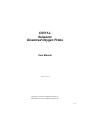
CS511-L
Sensorex
Dissolved Oxygen Probe
User Manual
Issued 18.3.13
Copyright © 2001-2013 Campbell Scientific Inc.
Printed under licence by Campbell Scientific Ltd.
CSL 560
Guarantee
This equipment is guaranteed against defects in materials and workmanship.
This guarantee applies for twelve months from date of delivery. We will
repair or replace products which prove to be defective during the guarantee
period provided they are returned to us prepaid. The guarantee will not apply
to:
•
Equipment which has been modified or altered in any way without the
written permission of Campbell Scientific
•
Batteries
•
Any product which has been subjected to misuse, neglect, acts of God or
damage in transit.
Campbell Scientific will return guaranteed equipment by surface carrier
prepaid. Campbell Scientific will not reimburse the claimant for costs incurred
in removing and/or reinstalling equipment. This guarantee and the Company’s
obligation thereunder is in lieu of all other guarantees, expressed or implied,
including those of suitability and fitness for a particular purpose. Campbell
Scientific is not liable for consequential damage.
Please inform us before returning equipment and obtain a Repair Reference
Number whether the repair is under guarantee or not. Please state the faults as
clearly as possible, and if the product is out of the guarantee period it should
be accompanied by a purchase order. Quotations for repairs can be given on
request. It is the policy of Campbell Scientific to protect the health of its
employees and provide a safe working environment, in support of this policy a
“Declaration of Hazardous Material and Decontamination” form will be
issued for completion.
When returning equipment, the Repair Reference Number must be clearly
marked on the outside of the package. Complete the “Declaration of
Hazardous Material and Decontamination” form and ensure a completed copy
is returned with your goods. Please note your Repair may not be processed if
you do not include a copy of this form and Campbell Scientific Ltd reserves
the right to return goods at the customers’ expense.
Note that goods sent air freight are subject to Customs clearance fees which
Campbell Scientific will charge to customers. In many cases, these charges are
greater than the cost of the repair.
Campbell Scientific Ltd,
Campbell Park, 80 Hathern Road,
Shepshed, Loughborough, LE12 9GX, UK
Tel: +44 (0) 1509 601141
Fax: +44 (0) 1509 601091
Email: [email protected]
www.campbellsci.co.uk
PLEASE READ FIRST
About this manual
Please note that this manual was originally produced by Campbell Scientific Inc. primarily for the
North American market. Some spellings, weights and measures may reflect this origin.
Some useful conversion factors:
Area: 1 in2 (square inch) = 645 mm2
Length:
1 in. (inch) = 25.4 mm
1 ft (foot) = 304.8 mm
1 yard = 0.914 m
1 mile = 1.609 km
Mass:
1 oz. (ounce) = 28.35 g
1 lb (pound weight) = 0.454 kg
Pressure:
1 psi (lb/in2) = 68.95 mb
Volume:
1 UK pint = 568.3 ml
1 UK gallon = 4.546 litres
1 US gallon = 3.785 litres
In addition, while most of the information in the manual is correct for all countries, certain information
is specific to the North American market and so may not be applicable to European users.
Differences include the U.S standard external power supply details where some information (for
example the AC transformer input voltage) will not be applicable for British/European use. Please
note, however, that when a power supply adapter is ordered it will be suitable for use in your country.
Reference to some radio transmitters, digital cell phones and aerials may also not be applicable
according to your locality.
Some brackets, shields and enclosure options, including wiring, are not sold as standard items in the
European market; in some cases alternatives are offered. Details of the alternatives will be covered in
separate manuals.
Part numbers prefixed with a “#” symbol are special order parts for use with non-EU variants or for
special installations. Please quote the full part number with the # when ordering.
Recycling information
At the end of this product’s life it should not be put in commercial or domestic refuse
but sent for recycling. Any batteries contained within the product or used during the
products life should be removed from the product and also be sent to an appropriate
recycling facility.
Campbell Scientific Ltd can advise on the recycling of the equipment and in some cases
arrange collection and the correct disposal of it, although charges may apply for some
items or territories.
For further advice or support, please contact Campbell Scientific Ltd, or your local agent.
Campbell Scientific Ltd, Campbell Park, 80 Hathern Road, Shepshed, Loughborough, LE12 9GX, UK
Tel: +44 (0) 1509 601141 Fax: +44 (0) 1509 601091
Email: [email protected]
www.campbellsci.co.uk
Contents
PDF viewers: These page numbers refer to the printed version of this document. Use the
PDF reader bookmarks tab for links to specific sections.
1. Introduction ................................................................. 1
2. Cautionary Statements............................................... 2
3. Initial Inspection ......................................................... 2
3.1
Shipping Kit and Accessories ................................................................ 2
3.1.1 Shipping Kit .................................................................................... 2
3.1.2 Optional Probe Accessories ............................................................ 2
4. Quickstart .................................................................... 3
4.1
4.2
4.3
Getting Probe Ready to Use................................................................... 3
Use SCWin to Program Datalogger and Generate Wiring Diagram .... 5
Mount Probe ........................................................................................... 8
5. Overview ...................................................................... 8
6. Specifications ............................................................. 9
7. Operation ................................................................... 11
7.1
7.2
Wiring ................................................................................................... 11
Programming ........................................................................................ 11
7.2.1 CRBasic ........................................................................................ 11
7.2.1.1 Example CR1000 Program Using VoltDiff ...................... 12
7.2.1.2 Example CR200(X) Program ............................................ 13
7.2.2 Edlog ............................................................................................. 13
7.2.2.1 Portion of CR10X Sample Program Using P1 .................. 14
7.2.2.2 Portion of CR10X Sample Program Using P2 .................. 14
7.3
Calibration ............................................................................................ 14
8. Maintenance .............................................................. 16
8.1
Cleaning Probe and Replacing the Membrane .................................... 16
i
Appendices
A. Dissolved Oxygen Tables ...................................... A-1
B. Sensorex’s Model DO6200/T .................................. B-1
B.1
B.2
DO6200/T Specifications...................................................................B-1
Accessories for DO6200/T ................................................................B-2
C. PT4-L Agitator ......................................................... C-1
C.1
C.2
C.3
Description .........................................................................................C-1
PT4-L Specifications..........................................................................C-2
Agitator Control .................................................................................C-2
1-1.
8-1.
8-2.
8-3.
8-4.
8-5.
8-6.
B-1.
C-1.
C-2.
C-3.
The CS511-L is currently Sensorex’s DO6400/T (left). The
DO6200/T (right) was shipped prior to June 2008 (refer to
Appendix B). ......................................................................................1
Separate the lower body from the upper body.....................................16
Remove membrane and O-ring ............................................................17
Using a toothbrush to clean probe .......................................................18
Proper O-ring placement ......................................................................19
Installing membrane .............................................................................20
Check for leakage .................................................................................21
Sensorex’s model DO6200/T.............................................................B-1
Preventing Bio-fouling of a DO Sensor ............................................C-1
DO sensor with PT4 Agitator ............................................................C-2
Agitator Wiring ..................................................................................C-3
7-1.
7-2.
7-3.
Sensor Wiring .......................................................................................11
Wiring for Example 1 ..........................................................................12
Wiring for Example 2 ..........................................................................13
Figures
Tables
ii
CS511-L Dissolved Oxygen Probe
1.
Introduction
The CS511 is a rugged, low-maintenance sensor that is manufactured by Sensorex.
It consists of a self-polarizing galvanic cell that generates a millivolt signal
proportional to the amount of oxygen present in the measured medium (typically
water).
Before installing the CS511, please study
•
•
•
NOTE
Section 2, Cautionary Statements
Section 3, Initial Inspection
Section 3.1, Quickstart
Currently, the CS511 is Sensorex’s Model DO6400/T. Prior to June
2008, the CS511 was Sensorex’s Model DO6200/T. Programming,
wiring, and most specifications are the same for these two sensors.
However, they use different accessories and look different (see Figure
1-1). Refer to Appendix B if you have Sensorex’s Model DO6200/T.
DO6200/T
DO6400/T
Figure 1-1. The CS511-L is currently Sensorex’s DO6400/T (left). The
DO6200/T (right) was shipped prior to June 2008 (refer to Appendix B).
1
CS511-L Dissolved Oxygen Probe
2.
3.
Cautionary Statements
•
The CS511 is a precision instrument. Please handle it with care.
•
Because the CS511 is shipped dry, electrolyte needs to be added before using
the probe (see Section 4.1, Getting Probe Ready to Use).
•
Letting the CS511 dry up shortens the life of the membrane and probe.
•
Drain the solution from the CS511 before storing it out of water.
•
Replace the membrane and recalibrate the probe before redeploying the CS511
after it has been stored out of water or dried up in the field.
Initial Inspection
3.1
•
Upon receipt of the CS511, inspect the packaging and contents for damage.
File damage claims with the shipping company.
•
Immediately check package contents against the shipping documentation (see
Section 3.1, Shipping Kit and Accessories). Contact Campbell Scientific about
any discrepancies.
•
The model number and cable length are printed on a label at the connection end
of the cable. Check this information against the shipping documents to ensure
the expected product and cable length are received.
Shipping Kit and Accessories
NOTE
Except for the agitator, these items are for Sensorex’s DO6400/T.
Refer to Appendix B if you have a DO6200/T.
3.1.1 Shipping Kit
(1) Membrane replacement tool
(1) Bottled DO electrolyte, 250 ml
(2) Teflon membranes
(2) Membrane O-rings
(2) Membrane spaces
3.1.2 Optional Probe Accessories
2
•
PT4─L Agitator with Repeat Cycle Timer for stagnant conditions (see Appendix
C)
•
#22261 Maintenance Kit containing (5) Teflon membranes, (5) membrane
O-rings, (5) tensioning washers, and a 250-ml bottle of electrolyte
•
#22262 Maintenance Kit containing (25) Teflon membranes, (25) membrane Orings, (25) tensioning washers, and a 500-ml bottle of electrolyte
•
#22263 Spare Parts Kit containing (2) membrane locks, (2) tensioning washers, (2)
body O-rings, and (1) membrane-replacement tool
User Manual
4.
Quickstart
Please review Section 7, Operation, for wiring, programming, and calibration
information.
4.1
Getting Probe Ready to Use
1.
2.
Unscrew the lower body from the upper body.
Inspect the membrane for wrinkles. Replace membrane if wrinkled (see
Section 8.1, Cleaning Probe and Replacing the Membrane).
3
CS511-L Dissolved Oxygen Probe
3.
Pour clean water into the lower body and look for leakage around the
membrane. Dispose of the water, and if there is leakage, replace membrane
(see Section 8.1, Cleaning Probe and Replacing the Membrane).
4.
Pour fresh electrolyte in the bottom cap and fill to the top of the cap.
5.
Keep the probe upright with the cable pointed upwards (not sideways). Screw
the bottom cap onto the upper body until hand tight.
r
W
a
te
NOTE
4
Excess electrolyte will leak out at the joint between the probe’s cap
and upper body.
User Manual
4.2
Use SCWin to Program Datalogger and Generate Wiring
Diagram
The simplest method for programming the datalogger to measure the 034B is to use
Campbell Scientific’s SCWin Program Generator.
1.
Open Short Cut and click on New Program.
2.
Select the datalogger and enter the scan interval.
5
CS511-L Dissolved Oxygen Probe
6
3.
Select CS511 Dissolved Oxygen Probe, and select the right arrow (in centre
of screen) to add it to the list of sensors to be measured, and then select Next.
4.
Define the name of the public variables and enter the calibration multiplier.
Variables default to DOmv for the millivolt measurements and DOppm for the
ppm values. The default calibration value of 0.34 is based on an average. It is
preferable to calibrate the probe using the procedure provided in Section 7.3,
Calibration. After entering the information, click on OK, and then select Next.
User Manual
NOTE
5.
Choose the outputs and then select Finish.
6.
In the Save As window, enter an appropriate file name and select Save.
7.
In the Confirm window, click Yes to download the program to the datalogger.
8.
Click on Wiring Diagram and wire according to the wiring diagram generated
by SCWin Short Cut.
Campbell Scientific also recommends connecting the shield wire to
ground.
7
CS511-L Dissolved Oxygen Probe
4.3
Mount Probe
Mount the CS511 in water at a slight angle, which prevents bubbles from becoming
trapped on the membrane.
5.
Overview
The CS511 is a galvanic probe which produces a millivolt signal proportional to the
amount of oxygen present in the measured medium. Oxygen diffuses through the
membrane onto the cathode, reacts chemically, and combines with the anode. An
electrical current is produced by this chemical reaction which is converted from
microamps to millivolts by an in-line resistor. An in-line thermistor also conditions
the signal providing automatic temperature compensation. With these features, the
probe produces a linear, millivolt output proportional to the oxygen present in the
medium in which it is placed.
The probe consists of two parts, an upper part with cathode, anode, and cable, and a
lower part comprising of a screw-on membrane cap. The probe is shipped dry, but
has a membrane installed in the cap. With the membrane in place, the cap must be
filled with electrolyte solution before the cap is screwed onto the top component.
The probe is self-polarizing and requires no external power source.
The probe's robust construction and simple design make maintenance and servicing
it straightforward. There is no need to send the probe back to the factory for
8
User Manual
servicing. It uses a strong, easy-to-clean, and easy-to-change membrane in a screwon membrane cap. Regular servicing is not required. When necessary, the probe
can be fully overhauled in five min.
The CS511’s cable can terminate in:
•
•
6.
Connector that attaches to a prewired enclosure (option –PW). Refer to
www.campbellsci.com/prewired-enclosures for more information.
Connector that attaches to a CWS900 Wireless Sensor Interface (option –
CWS). The CWS900 allows the probe to be used in a wireless sensor
network. Refer to www.campbellsci.com/cws900 for more information.
Specifications
Features:
•
In-line thermistor provides automatic temperature compensation
•
Agitator available that keeps the probe clean and moves water across
membrane for more accurate readings
•
Compatible with all Campbell Scientific dataloggers
Compatible Dataloggers:
CR200(X)-series
CR800 series
CR1000
CR3000
CR5000
CR9000X
CR510
CR10(X)
CR23X
CR7
21X
Principle of Measurement:
Membrane-covered, galvanic oxygen probe
Output Signal:
33 mV ± 9 mV (100% saturation),
< 2 mV (0% saturation)
Accuracy:
Better than ± 2% of reading ± 1 digit when
calibration temperature equals measuring
temperature ± 5°C
Response Time:
5 min. from 100% to 0% oxygen
Materials of Construction:
Body:
Anode:
Cathode:
Noryl
Silver
Zinc
Diameter:
5.72 cm (2.25 in)
Height:
17.78 cm (7 in) from bottom of sensor to end
of cable-strain relief
Shipping Weight
0.8 kg (1.75 lb)
Cable Jacket Material:
PVC
Operating Conditions:
Temperature
Pressure:
Minimum Submersion Depth:
0° to 50°C (32° to 122°F)
0 to 100 psig
60 mm (2.5 in)
9
CS511-L Dissolved Oxygen Probe
Minimum Water Flow:
5 cm/s (2 in/sec) across membrane
Calibration:
In air or in air saturated water
Temperature Compensation:
Automatic from 4° to 40°C (40° to 104°F)
Range of Dissolved Oxygen:
0.5 to 50 ppm
Probe Electrolyte:
NaCl + glycerol (prevents freezing)
red wire (+)
black wire (-)
black waterproof
cable (10ft length standard)
flexible cable
strain relief
Noryl Body
0.99”
7.00"
(25.1mm)
(177.8mm)
2.25”
(57.2mm)
10
User Manual
7.
Operation
7.1
Wiring
The CS511 can use one differential channel or one single-ended channel. Differential
wiring is better at rejecting electrical noise and ground loop error.
Table 7-1. Sensor Wiring
7.2
CR510, CR10X, CR800,
CR850, CR23X, CR1000,
CR3000, CR5000
CR200(X)-Series
Colour
Function
White
Signal +
Differential High,
or Single-Ended Channel
Single-Ended Channel
Black
Signal -
Differential Low or AG
Ground
Clear
Shield
Ground
Ground
Programming
NOTE
This section describes using CRBasic or Edlog to program the
datalogger. See Section 4.2, Use SCWin to Program Datalogger and
Generate Wiring Diagram, if using Short Cut.
Dataloggers that use CRBasic include the CR200(X)-series, CR800, CR850,
CR1000, CR3000, and CR5000. Dataloggers that use Edlog include the CR510,
CR10X, and CR23X. CRBasic and Edlog are included with LoggerNet and PC400
software.
7.2.1 CRBasic
In the CR800, CR850, CR1000, CR3000, and CR5000, VoltDiff() or VoltSE() can
be used to measure the CS511. In the CR200(X)-series dataloggers, only the
VoltSE() instruction can be used since these dataloggers do not support differential
measurements. Example programs are provided in Section 7.2.1.1, Example
CR1000 Program Using VoltDiff, and Section 7.2.1.2, Example CR200(X)
Program.
11
CS511-L Dissolved Oxygen Probe
7.2.1.1 Example CR1000 Program Using VoltDiff
This example is a CR1000 program but programming for the CR800, CR850,
CR3000, and CR5000 is similar. Table 7-2 shows the wiring for the example.
Table 7-2. Wiring for CR1000 Example
CR1000 Connection
Sensor Wire
1H
White
1L
Black
Ground
Clear
'CR1000
'Declare Variables and Units
Public Batt_Volt
Public DOmV
Public DOppm
Units Batt_Volt=Volts
Units DOmV=mV
Units DOppm=ppm
'Define Data Tables
DataTable(Table1,True,-1)
DataInterval(0,60,Min,10)
Sample(1,DOmV,FP2)
Sample(1,DOppm,FP2)
Sample(1,Batt_Volt,FP2)
EndTable
DataTable(Table2,True,-1)
DataInterval(0,1440,Min,10)
Minimum(1,Batt_Volt,FP2,False,False)
EndTable
'Main Program
BeginProg
Scan(5,Sec,1,0)
'Default Datalogger Battery Voltage measurement Batt_Volt:
Battery(Batt_Volt)
'CS511 Dissolved Oxygen Probe measurements DOmV and DOppm:
VoltDiff(DOmV,1,mV250,1,True,0,_60Hz,1,0)
DOppm=DOmV*0.34
'Call Data Tables and Store Data
CallTable(Table1)
CallTable(Table2)
NextScan
EndProg
12
User Manual
7.2.1.2 Example CR200(X) Program
The CR200(X)-series must use the VoltSE() instruction since these dataloggers do
not make differential measurements. If the other CRBasic dataloggers use the
VoltSE() instruction instead of the VoltDiff() instruction, their programming will
be similar to this example. Table 7-3 shows the wiring for the example.
Table 7-3. Wiring for CR200(X) Example
CR200(X) Connection
Sensor Wire
SE1
White
Ground
Black
Ground
Clear
'CR200(X) Series
'Declare Variables and Units
Public Batt_Volt
Public DOmV
Public DOppm
Units Batt_Volt=Volts
Units DOmV=mV
Units DOppm=ppm
'Define Data Tables
DataTable(Table1,True,-1)
DataInterval(0,60,Min)
Sample(1,DOmV)
EndTable
DataTable(Table2,True,-1)
DataInterval(0,1440,Min)
Minimum(1,Batt_Volt,False,False)
EndTable
'Main Program
BeginProg
Scan(10,Sec)
'Default Datalogger Battery Voltage measurement Batt_Volt:
Battery(Batt_Volt)
'CS511 Dissolved Oxygen Probe measurements DOmV and DOppm:
VoltSE(DOmV,1,1,1,0)
DOppm=DOmV*0.34
'Call Data Tables and Store Data
CallTable(Table1)
CallTable(Table2)
NextScan
EndProg
7.2.2 Edlog
In Edlog, P1 is used for single-ended measurements, and P2 is used for differential
measurements. Section 7.2.2.1, Portion of CR10X Sample Program Using P1, and
Section 7.2.2.2, Portion of CR10X Sample Program Using P2, provide examples.
13
CS511-L Dissolved Oxygen Probe
7.2.2.1 Portion of CR10X Sample Program Using P1
NOTE
1: Volt (SE) (P1)
1: 1
2: 24
3: 1
4: 1
5: 1.0
6: 0.0
The example measurement instructions that follow do not store data
to final storage. Additional instructions (typically P92, P77, and
output processing instructions such as P70) are required to store data
permanently.
Reps
250 mV 60 Hz Rejection Range ; code 23 used for CR23X
SE Channel
Loc [ DOmV ]
Multiplier
*See Calibration*
Offset
7.2.2.2 Portion of CR10X Sample Program Using P2
NOTE
1: Volt (Diff) (P2)
1: 1
2: 24
3: 1
4: 1
5: 1.0
6: 0.0
7.3
The example measurement instructions that follow do not store data
to final storage. Additional instructions (typically P92, P77, and
output processing instructions such as P70) are required to store data
permanently.
Reps
250 mV 60 Hz Rejection Range ; code 23 used for CR23X
DIFF Channel
Loc [ DOmV ]
Multiplier
*See Calibration*
Offset
Calibration
The multiplier is used to calibrate the CS511 probe. To calculate the multiplier:
1) Program the datalogger using a multiplier of one (see Section 4.2, Use SCWin to
Program Datalogger and Generate Wiring Diagram, or Section 7.2,
Programming).
2) Wire the CS511 to the datalogger (see wiring diagram generated by SCWin or see
Section 7.1, Wiring).
3) If the CS511 has been deployed in the field, gently wipe the membrane with a soft
cloth.
4) Place the CS511 in air away from direct sunlight with the membrane facing
upward.
5) Place a drop of clean water on the membrane.
6) Wait for readings to stabilize. This may take 15 minutes or more.
7) Determine the air temperature and barometric pressure.
8) Using a calibration chart such as that provided in Appendix A, determine the
oxygen concentration of the air.
14
User Manual
9) Use the following equation to calculate the multiplier:
M = P/R
where:
M = Multiplier
P = Concentration in PPM of the air (from the calibration chart)
R = The signal output of the probe when using a multiplier of one
10) Change the multiplier in the datalogger program from one to the calculated
number (see Section 4.2, Use SCWin to Program Datalogger and Generate
Wiring Diagram, or Section 7.2, Programming).
Instead of step 10, the multiplier can be entered using a separate instruction in the
program. This will allow a new multiplier to be added to the program without
rewriting, compiling, and downloading the program to the datalogger.
For this method, CRBasic dataloggers can use the following expression. The
multiplier value is entered into the expression through the Public Table using the
numeric display in PC200W, LoggerNet, PC400, PConnect, PConnectCE, or
datalogger keyboard display.
CRBasic Expression for Entering Multiplier:
DOppm = DOMult * DOmV
Edlog dataloggers use Instruction 36. The multiplier is entered into an input
location called DOmult using the numeric display in PC200W, PC208W,
LoggerNet, PC400, PConnect, PConnectCE, or the datalogger keyboard display.
Edlog Instruction 36 for Entering Multiplier:
57: Z=X*Y (P36)
1: 1
X Loc [ DOmV
2: 2
Y Loc [ DOmult
3: 3
Z Loc [ DOppm
]
]
]
15
CS511-L Dissolved Oxygen Probe
8.
Maintenance
The only maintenance required is regular cleaning and replacement of the
membrane (see below).
8.1
Cleaning Probe and Replacing the Membrane
1.
Unscrew the lower body from the upper body (Figure 8-1).
Figure 8-1. Separate the lower body from the upper body
2.
16
Safely dispose of the electrolyte. Make sure the cap’s O-ring does not fall out
of the cap.
User Manual
3.
Using the membrane tool, unscrew the membrane lock that is in the lower body
(see Figure 8-2).
4.
Remove and dispose of the membrane and its O-ring as show in Figure 8-2.
Membrane Tool
Membrane Lock
Spacer
Membrane
Membrane O-ring
Cap O-ring
Figure 8-2. Remove membrane and O-ring
17
CS511-L Dissolved Oxygen Probe
5.
To clean, immerse the top part of the sensor in distilled white vinegar (3%
acetic acid) for about 30 min. If vinegar is unavailable, use a soft toothbrush,
automatic dishwasher detergent, and clean water to clean the cathode, anode,
and plastic. Rinse all components thoroughly with clean water after cleaning
(see Figure 8-3).
Figure 8-3. Using a toothbrush to clean probe
18
User Manual
6.
Replace the membrane and its O-ring by first placing the new O-ring at the
very bottom of the membrane cavity (see Figure 8-4). Remove the paper
backing from a new membrane and place the new membrane on top of the Oring, and then place the spacer on top of the membrane. Using the membrane
tool, install the membrane lock on top of the spacer as shown in Figure 8-5.
Make sure the cap is upright (not sideways) when securing the membrane lock
to the spacer.
Figure 8-4. Proper O-ring placement
19
CS511-L Dissolved Oxygen Probe
Membrane Tool
Membrane Lock
Spacer
Membrane
O-ring
Figure 8-5. Installing membrane
7.
20
Inspect the membrane for wrinkles; replace membrane if wrinkled.
User Manual
8.
Pour some clean water into the lower body and look for leakage around the
membrane (see Figure 8-6); replace membrane if there is leakage. If there is no
leakage, dispose of the water.
r
W
a
te
Figure 8-6. Check for leakage
9.
Pour fresh electrolyte in the bottom cap and fill to the top of the cap.
10. Keep the sensor upright so that the cable is pointed upwards (not sideways).
Screw the bottom cap onto the upper body until hand tight.
NOTE
Excess electrolyte will leak out at the joint between the sensor’s cap
and upper body.
21
CS511-L Dissolved Oxygen Probe
22
Appendix A. Dissolved Oxygen Tables
A-1
Appendix A. Dissolved Oxygen Tables
A-2
Appendix B. Sensorex’s Model DO6200/T
Prior to June 2008, Campbell Scientific’s CS511 was Sensorex’s model DO6200/T
(see Figure B-1) instead of Sensorex’s model DO6400/T. Programming, wiring,
and some specifications are the same for these two sensors. However, they look
different and use different accessories.
Figure B-1. Sensorex’s model DO6200/T
B.1 DO6200/T Specifications
Principle of Measurement:
Membrane covered, galvanic oxygen probe
Output Signal:
1.65 mV ± 0.45 mV per mg/l
Accuracy:
Better than ± 2 % of reading ± 1 digit when
calibration temperature equals measuring
temperature ± 5°C
Output Impedance:
10 kΩ nominal
Response Time:
After equilibration, 2 min. for 90% of final
value
Materials of Construction:
Probe body:
O-rings:
Membrane:
Dimensions and Weight:
Delrin
Membrane O-ring = Buna N
Body Seal O-ring = Viton
0.05 mm Teflon
8.9 cm (3.5 in) height, 5.6 cm (2.2 in)
diameter, 0.5 kg (1.1 lb)
B-1
Appendix B. Sensorex’s Model DO6200/T
Cable Length:
3 m (10 ft)
Cable Description:
5-wire, 22 AWG-shielded, PVC jacketed
Operating Conditions:
Temperature
Pressure:
Minimum Submersion Depth:
Minimum Water Flow:
0° to 50°C (32° to 122°F)
Maximum 10 atmospheres (147 psig)
60 mm (2.5 in)
5 cm/s (2 in/sec) across membrane
Calibration:
In air or in air saturated water
Temperature Compensation:
Automatic from 4° to 40°C (40° to 104°F)
Range of Dissolved Oxygen:
0 to 20 mg/l, 0 to 200 % saturated
Electrode Materials:
Ag cathode/Zn anode
Probe Electrolyte:
NaCl
B.2 Accessories for DO6200/T
#14054 Teflon Membrane for DO6200/T (Qty 5)
#14053 Teflon Membrane for DO6200/T (Qty 25)
#14056 Membrane Replacement Tool for DO6200/T
#14055 DO Electrolyte for DO6200/T, 500 ml
B-2
Appendix C. PT4-L Agitator
C.1 Description
The PT4 agitator is a reliable, robust agitator for use in conjunction with probes
subjected to bio-fouling in ponds and stagnant water conditions (flow <5 cm/s).
O2 probes require a minimum water velocity across their membranes to function
properly. Therefore, to measure DO in stagnant water conditions, it is necessary to
move the water past the membrane to get accurate and reliable DO measurements. In
many instances, the water also has a high bio-loading and the probes become fouled
resulting in inaccurate DO measurements.
Figure C-1. Preventing Bio-fouling of a DO Sensor
The PT4 agitator overcomes these problems. The device is designed so that a softbristle brush sweeps across the probe membrane or sensor tip. This sweeping action of
the brush provides the required water velocity as well as prevents the membrane from
becoming bio-fouled.
The optimum sweeping frequency depends on the design of the probe and type of
membrane used and water conditions. An ON-time of 0.25 s and OFF-time of 5 s is
suitable in most circumstances.
C-1
Appendix C. PT4-L Agitator
Figure C-2. DO sensor with PT4 Agitator
C.2 PT4-L Specifications
Diameter:
8.3 cm (3.25 in)
Length:
18.0 cm (7.125 in)
Weight:
0.6 kg (1.25 lb)
Cable length:
3 m (10 ft)
Power requirements:
10.5 to 18 Vdc at the agitator
Active current consumption: 1.1 A
Maximum ON time:
3s
C.3 Agitator Control
Campbell Scientific ships the agitator with a repeat cycle timer. Using the repeatcycle timer requires no datalogger programming. However, some users choose to
use a solid-state relay and have the datalogger agitate the water on the probe face
either periodically throughout the day or just before measurement. Agitating just
before the measurement saves on power and causes less wear and tear on the
agitator and probe membrane.
C-2
Appendix C. PT4-L Agitator
The wiring for the agitator as controlled by this example program is as follows:
Gro und/G
4
Datalogger
Port C1
WHITE
1
Agitator
#7321 Relay
Crydo m D1D07
3
2
BLUE
+
12 V Battery
Figure C-3. Agitator Wiring
The following instructions would trigger the agitator as discussed in the agitator
manual.
The CR800, CR850, CR1000, CR3000, and CR5000 use the Portset() instruction as
follows:
CR1000 Portset() Instruction Example
Portset (1,1)
Delay (1,500,msec)
Portset (1,0)
The CR200(X)-series use the Portset() instruction as follows:
CR200(X) Portset() Instruction Example
Portset (1,1)
Delay(500,msec)
Portset(1,0)
C-3
Appendix C. PT4-L Agitator
The CR510, CR10X, and CR23X use instruction P86 and P22 as follows:
CR10X P86 and P22 Instructions Example
45: Do (P86)
1: 41
Set Port 1 High
46: Excitation with Delay (P22)
1: 1
Ex Channel
2: 20
Delay W/Ex (units = 0.01 sec)
3: 0
Delay After Ex (units = 0.01 sec)
4: 0
mV Excitation
47: Do (P86)
1: 51
Set Port 1 Low
48: End (P95)
The above examples are not as power efficient as possible and would require AC
power to maintain a sufficient battery charge. If it is necessary to operate an
agitator without AC power available, write the program so that the agitator is only
operated for a short period of time just before the measurement is to be taken.
C-4
CAMPBELL SCIENTIFIC COMPANIES
Campbell Scientific, Inc. (CSI)
815 West 1800 North
Logan, Utah 84321
UNITED STATES
www.campbellsci.com • [email protected]
Campbell Scientific Africa Pty. Ltd. (CSAf)
PO Box 2450
Somerset West 7129
SOUTH AFRICA
www.csafrica.co.za • [email protected]
Campbell Scientific Australia Pty. Ltd. (CSA)
PO Box 8108
Garbutt Post Shop
QLD 4814 AUSTRALIA
www.campbellsci.com.au • [email protected]
Campbell Scientific do Brazil Ltda. (CSB)
Rua Luisa Crapsi Orsi, 15 Butantã
CEP: 005543-000 São Paulo SP BRAZIL
www.campbellsci.com.br • [email protected]
Campbell Scientific Canada Corp. (CSC)
11564 - 149th Street NW
Edmonton, Alberta T5M 1W7
CANADA
www.campbellsci.ca • [email protected]
Campbell Scientific Centro Caribe S.A. (CSCC)
300N Cementerio, Edificio Breller
Santo Domingo, Heredia 40305
COSTA RICA
www.campbellsci.cc • [email protected]
Campbell Scientific Ltd. (CSL)
Campbell Park
80 Hathern Road
Shepshed, Loughborough LE12 9GX
UNITED KINGDOM
www.campbellsci.co.uk • [email protected]
Campbell Scientific Ltd. (France)
3 Avenue de la Division Leclerc
92160 ANTONY
FRANCE
www.campbellsci.fr • [email protected]
Campbell Scientific Spain, S. L.
Avda. Pompeu Fabra 7-9
Local 1 - 08024 BARCELONA
SPAIN
www.campbellsci.es • [email protected]
Campbell Scientific Ltd. (Germany)
Fahrenheitstrasse13, D-28359 Bremen
GERMANY
www.campbellsci.de • [email protected]
Please visit www.campbellsci.com to obtain contact information for your local US or International representative.