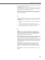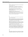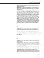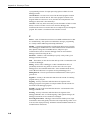
1
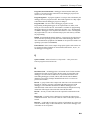
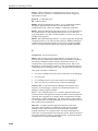
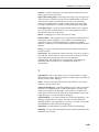
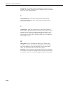
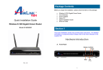
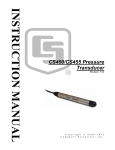
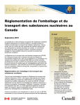
INSTRUCTION MANUAL
Device Configuration Utility
(DevConfig)
Version 1.2
Revision: 5/05
C o p y r i g h t ( c ) 1 9 9 9 - 2 0 0 5
C a m p b e l l S c i e n t i f i c , I n c .
License for Use
This software is protected by both United States copyright law and
international copyright treaty provisions. The installation and use of this
software constitutes an agreement to abide by the provisions of this license
agreement.
You may make a copy of this software on a second computer for the sole
purpose of backing-up CAMPBELL SCIENTIFIC, INC. software and
protecting your investment from loss. This software may not be sold, included
or redistributed in any other software, or altered in any way without prior
written permission from Campbell Scientific. All copyright notices and
labeling must be left intact.
This is a blank page.
Limited Warranty
CAMPBELL SCIENTIFIC, INC. warrants that the installation media on which
the accompanying computer software is recorded and the documentation
provided with it are free from physical defects in materials and workmanship
under normal use. CAMPBELL SCIENTIFIC, INC. warrants that the
computer software itself will perform substantially in accordance with the
specifications set forth in the instruction manual published by CAMPBELL
SCIENTIFIC, INC.
CAMPBELL SCIENTIFIC, INC. will either replace or correct any software
that does not perform substantially according to the specifications set forth in
the instruction manual with a corrected copy of the software or corrective code.
In the case of significant error in the installation media or documentation,
CAMPBELL SCIENTIFIC, INC. will correct errors without charge by
providing new media, addenda or substitute pages.
If CAMPBELL SCIENTIFIC, INC. is unable to replace defective media or
documentation, or if CAMPBELL SCIENTIFIC, INC. is unable to provide
corrected software or corrected documentation within a reasonable time,
CAMPBELL SCIENTIFIC, INC. will either replace the software with a
functionally similar program or refund the purchase price paid for the software.
The above warranties are made for ninety (90) days from the date of original
shipment.
CAMPBELL SCIENTIFIC, INC. does not warrant that the software will meet
licensee’s requirements or that the software or documentation are error free or
that the operation of the software will be uninterrupted. The warranty does not
cover any diskette or documentation that has been damaged or abused. The
software warranty does not cover any software that has been altered or
changed in any way by anyone other than CAMPBELL SCIENTIFIC, INC.
CAMPBELL SCIENTIFIC, INC. is not responsible for problems caused by
computer hardware, computer operating systems or the use of CAMPBELL
SCIENTIFIC, INC.’s software with non-CAMPBELL SCIENTIFIC, INC.
software.
ALL WARRANTIES OF MERCHANTABILITY AND FITNESS FOR A
PARTICULAR PURPOSE ARE DISCLAIMED AND EXCLUDED.
CAMPBELL SCIENTIFIC, INC. SHALL NOT IN ANY CASE BE LIABLE
FOR SPECIAL, INCIDENTAL, CONSEQUENTIAL, INDIRECT, OR
OTHER SIMILAR DAMAGES EVEN IF CAMPBELL SCIENTIFIC HAS
BEEN ADVISED OF THE POSSIBILITY OF SUCH DAMAGES.
CAMPBELL SCIENTIFIC, INC. IS NOT RESPONSIBLE FOR ANY COSTS
INCURRED AS A RESULT OF LOST PROFITS OR REVENUE, LOSS OF
USE OF THE SOFTWARE, LOSS OF DATA, COST OF RE-CREATING
LOST DATA, THE COST OF ANY SUBSTITUTE PROGRAM, CLAIMS
BY ANY PARTY OTHER THAN LICENSEE, OR FOR OTHER SIMILAR
COSTS.
LICENSEE’S SOLE AND EXCLUSIVE REMEDY IS SET FORTH IN THIS
LIMITED WARRANTY. CAMPBELL SCIENTIFIC, INC.’S AGGREGATE
LIABILITY ARISING FROM OR RELATING TO THIS AGREEMENT OR
THE SOFTWARE OR DOCUMENTATION (REGARDLESS OF THE
FORM OF ACTION; E.G., CONTRACT, TORT, COMPUTER
MALPRACTICE, FRAUD AND/OR OTHERWISE) IS LIMITED TO THE
PURCHASE PRICE PAID BY THE LICENSEE.
Device Configuration Utility
Table of Contents
PDF viewers note: These page numbers refer to the printed version of this document. Use
the Adobe Acrobat® bookmarks tab for links to specific sections.
1. System Requirements and Installation...................1-1
1.1 Hardware and Software Requirements ................................................. 1-1
1.2 CD-ROM Installation ........................................................................... 1-1
1.3 DevConfig Operations and Backup Procedures ................................... 1-2
1.3.1 Backing Up Data......................................................................... 1-2
1.3.2 Loss of Computer Power ............................................................ 1-2
1.3.3 Restoring from Backup ............................................................... 1-3
2. Using the Device Configuration Utility ...................2-1
2.1
2.2
2.3
2.4
2.5
Overview .............................................................................................. 2-1
Main DevConfig Screen ....................................................................... 2-2
Downloading an Operating System ...................................................... 2-3
Terminal Tab ........................................................................................ 2-4
The Unknown Device Type.................................................................. 2-6
Appendix
A. Glossary of Terms................................................... A-1
i
This is a blank page.
Section 1. System Requirements and
Installation
1.1 Hardware and Software Requirements
Device Configuration Utility (DevConfig) is a 32-bit program designed to run
on Intel-based computers running Microsoft Windows operating systems.
Recommended platforms for running DevConfig include Windows NT,
Windows 2000, or Windows XP because they offer the most stable operating
environments. DevConfig may also run on Windows 95, Windows 98, or
Windows ME platforms if operations such as open screens are limited so as not
to exhaust the operating system’s resources. All installations require at least a
Pentium II or equivalent processor, a minimum of 64 MB of RAM, and a
minimum of 4 MB free space on the hard disk.
DevConfig also requires that TCP/IP support be installed on the PC.
1.2 CD-ROM Installation
NOTE
Some Campbell Scientific products automatically install
DevConfig with their other components. These installation
instructions are for a stand-alone installation of DevConfig.
The following instructions assume that drive D: is a CD-ROM drive on the
computer from which the software is being installed. If the drive letter is
different, substitute the appropriate drive letter.
1.
Put the installation CD in the CD-ROM drive. The install application
should come up automatically. Skip to step 3.
2.
If the install does not start, then from the Windows system menu,
select Start | Run. Type “d:\setup.exe” in the Open field or use the
Browse button to access the CD-ROM drive and select the setup
executable. This activates the DevConfig Installation Utility.
3.
Follow the prompts on the screen to complete the installation. The
installation will require a CD key. You will find this code printed on
the original installation CD.
A shortcut to launch DevConfig is added to your computer’s Start menu under
Programs | DevConfig. If the default directories are used, DevConfig
executable files and help files are placed in the C:\Program
Files\CampbellSci\DevConfig directory.
Working directories will also be created under C:\Campbellsci for
DevConfig’s configurations and data files, user programs, and settings for the
accessory applications and utilities.
1-1
Section 1. System Requirements and Installation
1.3 DevConfig Operations and Backup Procedures
This section describes some of the concepts and procedures recommended for
routine operation and security of the DevConfig software. If software and
computer systems were perfect this section would not be necessary. However,
since this software is required to run with predictable results in the real world
on real computers, the following guidelines and procedures will be helpful in
minimizing possible problems.
1.3.1 Backing Up Data
As with any computer system that contains important information, the data
stored in the DevConfig data files should be backed up to a secure archive or
transferred to another system on a regular basis. This is a prudent measure in
case the hard disk crashes or the computer suffers some other hardware failure
that prevents access to the stored data on the disk.
To back up the files, DevConfig must be closed to prevent the underlying
communications engine from trying to access the files while they are being
copied for the backup. Once the files have been backed up, DevConfig may be
restarted.
The most direct approach is to close all Campbell Scientific software and back
up the entire C:\Campbellsci working directory. The content of each of the
subdirectories is summarized in the figure below. If default directories have
been used, this will back up the data files and the working files for
DevConfig’s communications engine. Note that these directories assume that
the installation used the default directory structure suggested by the install
utility. If a different working directory was used, then the files will be
contained in the same set of subdirectories, under the alternative main working
directory.
By default, data files are stored to the c:\CampbellSci\DevConfig directory.
DevConfig
Default directory for Device Configuration Utility saved settings files.
Lib
Libraries of settings supported by devices configured by the
DevConfig application.
1.3.2 Loss of Computer Power
DevConfig writes to files in its \SYS directory during normal operations.
These files may be open (or active) as long as data is being stored to the files.
If computer system power is lost while the DevConfig server is writing data to
the active cache and configuration files, these files can become corrupted,
making the files inaccessible. This is particularly a problem for Windows 95,
1-2
Section 1. System Requirements and Installation
98 and ME platforms using FAT32 disk file formatting. Windows NT, 2000,
and XP offer the choice of NTFS disk file formatting that provides a greater
protection for this type of event. Thus, Windows NT, 2000, and XP offer
more robust operation.
While loss of power won’t always cause a file to become corrupted, having
files backed up as described above will allow you to recover if a problem does
occur. If a file does get corrupted, all of the working files need to be restored
from backup to maintain internal synchronization.
1.3.3 Restoring from Backup
To restore DevConfig operation from a backup copy of the data and
configuration files, you must close DevConfig and any associated applications.
You can then copy and replace the files in DevConfig’s working directory with
the files from the backup. Any data collected or changes made to the network
since the last backup will be lost. Once all the files have been copied, you can
restart DevConfig.
1-3
Section 1. System Requirements and Installation
This is a blank page.
1-4
Section 2. Using the Device
Configuration Utility
This section provides information on the Device Configuration Utility (DevConfig), a
stand-along application launched by its own program shortcut. DevConfig is used to set
various settings, especially PakBus settings, on dataloggers as well as some
communications peripherals.1
2.1 Overview
The Device Configuration Utility (DevConfig) sets up dataloggers and
intelligent peripherals before those devices are deployed in the field and before
the devices are added to networks in Campbell Scientific datalogger support
software such as LoggerNet or PC400. Some key features of DevConfig
include:
•
To keep the process as simple as possible, DevConfig only supports
direct serial connections between the PC and devices.
•
LoggerNet or PC400 must be closed if you are running DevConfig.
Having LoggerNet or PC400 open will prevent communication with a
device.
•
DevConfig can not only send operating systems to supported device
types, but can also set datalogger clocks and send program files to
dataloggers.
•
DevConfig allows you to determine operating system types and
versions, which can be very useful in classic dataloggers1, such as the
CR10X, where the operating system version in the datalogger is not
known.
•
DevConfig provides a reporting facility where a summary of the
current configuration of a device can be shown on the screen and
printed. This configuration can also be saved to a file and used to
restore the settings in the same or a replacement device.
1
A note on datalogger terminology – Edlog dataloggers are those built around
the processor family used in CR10s, including the 21X, CR7, CR10, CR500,
CR10X, CR510, and CR23X. Some of these, specifically the last three, use
flash memory so that users can install alternative operating systems, such as
mixed-array, table-data (TD), or PakBus (PB) operating systems. CRBasic
dataloggers are built around a different processor family that uses a different
programming language, known as CRBasic. These include the CR200/205,
CR5000 and CR9000.
2-1
Section 2. Device Configuration Utility
•
Some devices may not support the configuration protocol in
DevConfig, but do allow configurations to be edited through the
terminal emulation screen.
•
Help for DevConfig is shown as prompts and explanations on its main
screen. Help for the appropriate settings for a particular device can
also be found in the user’s manual for that device.
•
Updates to DevConfig are available from Campbell Scientific's web
site. These may be installed over top of older versions.
2.2 Main DevConfig Screen
The DevConfig window is divided into two main sections: the device selection
panel on the left side and tabs on the right side. After choosing a device on the
left, you will then have a list of the serial ports (COM1, COM2, etc.) installed
on your PC. You’ll be offered a choice of baud rates only if the device
supports more than one baud rate in its configuration protocol. The page for
each device presents instructions about how to set up the device to
communicate with DevConfig. Different device types will offer one or more
tabs on the right.
When the user presses the Connect button, the device type, serial port, and
baud rate selector controls become disabled and, if DevConfig is able to
connect to the device, the button will change from "Connect" to "Disconnect".
The tabs on the right side of the window will be replaced with tabs that
represent the various operations that are available for that device in a
connected state. These operations can vary from device to device.
2-2
Section 2. Device Configuration Utility
Two common operations are sending a new operating system and
communicating with a device in terminal emulation mode. These two
operations are covered below. Refer to DevConfig’s embedded help or the
user manual for a device for more device-specific operations.
2.3 Downloading an Operating System
DevConfig can send operating systems from the send OS tab to all Campbell
Scientific devices with flash replaceable operating systems. An example for the
CR10X is shown below:
The text at right describes any interface devices or cabling required to connect
the PC to the device. Screens for other devices vary only in the text on the
right side. This screen differs from other screens that are available in
DevConfig in that it can be accessed from either a connected and disconnected
state.
When you click the Start button, DevConfig offers a file open dialog box to
prompt you for the operating system file (usually a *.obj file). You may be
required to cycle power to the device or press a special “program” button.
When the device issues the appropriate prompts, DevConfig starts to send the
operating system:
2-3
Section 2. Device Configuration Utility
When the operating system has been sent to the device, a message dialog will
appear similar to the one shown below:
The information in the dialog helps to corroborate the signature of the
operating system sent. For devices such as the CR10X (especially those with
extended memory) that can take a long time to reset following an OS
download, text warns you against interrupting the memory test.
2.4 Terminal Tab
The Terminal tab will be available when the application is connected to any
device type that can be communicated with in a remote terminal mode. The
Terminal tab offers a terminal emulator that can be useful in accessing settings
or status information that are not exposed in other windows. For example,
classic dataloggers with PakBus operating systems that are configured as
routers contain routing tables that list the other PakBus nodes that are known
to that datalogger. This routing table is only available through the *D17 mode
(see *D descriptions in the datalogger’s operators’ manuals) using the
keyboard/display or a terminal emulator. Another example is that the status
table in mixed-array dataloggers (*B) can also be accessed via an “S”
2-4
Section 2. Device Configuration Utility
command in terminal mode. This status information can provide important data
for troubleshooting purposes.
The default for the Terminal tab is to only show characters that are returned
from the device. However, if the Echo Input check box is enabled, the screen
will also display the characters actually typed by the user.
The All Caps Check Box controls whether the keyboard input will be forced
to upper case before the characters are sent to the device. It will be disabled for
some device types that require upper case input.
2-5
Section 2. Device Configuration Utility
2.5 The Unknown Device Type
When the Unknown device type is selected, a panel will be shown in the tab
control similar to that shown below:
Clicking Connect puts DevConfig into Terminal emulation mode on the Serial
Port and at the Baud Rate selected.
When you click on Identify Datalogger Type, DevConfig will attempt to
identify the type of device that is connected on the specified serial port. It will
attempt to communicate using each of the datalogger protocols (mixed-array,
table-data, and PakBus) in turn. If it fails to get any answer to any of these
attempts, the baud rate will be automatically changed and the various protocols
will be attempted again. When DevConfig recognizes the response from the
device and the device type is one of the supported types, that device type will
automatically be selected.
2-6
Appendix A. Glossary of Terms
A
Advise – See Data Advise
ASCII File - A computer file containing letters, numbers, and other characters
using the ASCII character encoding.
Asynchronous - The transmission of data between a transmitting and a
receiving device occurs as a series of zeros and ones. For the data to be "read"
correctly, the receiving device must begin reading at the proper point in the
series. In asynchronous communications, this coordination is accomplished by
having each character surrounded by one or more start and stop bits that
designate the beginning and ending points of the information (see
Synchronous). The transfer of information is not otherwise coordinated
between the sender and receiver.
Analog Channel - A terminal on the datalogger's wiring panel where leads for
analog signals are connected. The analog channels are designated single-ended
(SE) or differential (DIFF) on the wiring panel. Many sensors, such as
thermistor temperature probes and wind vanes, output analog signals.
Array-based Datalogger – See Mixed-array Datalogger.
B
Batch Files - An ACSII text file that contains one or more DOS commands or
executable file commands. When the batch file is run, the commands in the file
are executed sequentially.
Battery - This entry in the status table returns the datalogger battery voltage.
Baud - The rate at which a communication signal travels between two devices.
Binary File - A file based on software defined formatting. A binary file can
only be interpreted by the software programmed to decode the formatting. This
format is used for more efficient data storage than is provided by ASCII.
BMP (Block Mode Protocol) – The communications protocol used by the
server to communicate with table-based dataloggers and RF modems.
Broadcast – Part of the radio (RF) technique of polling remote radio modem
datalogger sites. A single modem sends a message (broadcast) that all affected
remotes hear and respond to.
A-1
Appendix A. Glossary of Terms
C
Call-back - When a datalogger is programmed for Call-back, it will
automatically call the host computer when a specified condition is met. The
computer must be set up to look for such an incoming call.
Call-back ID Number - A three-digit number that is used to identify what
datalogger has called the host computer. (Not available for Table-based
dataloggers.)
Cancel - Choosing Cancel from a dialog box will typically ignore any changes
made and close the box.
Carrier – An electrical signal used to convey data or other information. For
example, radio and phone modems use carrier signals. Phone modems attempt
to detect carrier when the call is placed. The red LED on the RF95T lights
when the modem detects a carrier.
Child Node – See Node. A node that is accessed through another device
(parent node). For example a remote radio frequency (RF) site is accessed
through and a child of the base RF232T. All nodes are child nodes of the PC.
Client – a software application designed to connect to a server. Usually
provides some type of user interface or data acquisition. Email programs
running on individual PCs are typically client applications that connect to an
email server program running on a computer at an Internet Service Provider to
receive and send email messages.
Coaxial cable – Special type of cable with two conductors (center conductor
and outer shield conductor). Classified by size, impedance, and loss
characteristics. Used to connect MD9 modems and to connect radios to
antennas.
Collection - (see Data Collection)
COM Port - A computer's serial communications port. Cables and other
interface devices are connected between the computer's COM port and the
datalogger.
Communication Server – The software (typically packaged as a DLL) that
provides the communications functions within other software such as
PC200W, PC400, or LoggerNet.
Control Port - Dataloggers have digital output ports that can be used to switch
power to sensors such as the HMP35C relative humidity circuit or to control
relays. These digital outputs are called Control Ports and are labeled C1, C2,
etc., on the wiring panel. Control ports on some dataloggers can also be used
as inputs to sense the digital (high or low) state of a signal, monitor pulse
signals, control Synchronous Devices for Measurement (SDM), or used as data
input/output connections for SDI-12 sensors.
CoraScript – A command line interpreter client to the LoggerNet server that
allows the user access to many of the capabilities of the LoggerNet server
using direct commands or programmed script files.
CR10X-TD Family of Dataloggers – Any of the Edlog dataloggers with
table-data operating systems become “TD” dataloggers, including the CR10T,
CR510-TD, CR10X-TD, and CR23X-TD.
A-2
Appendix A. Glossary of Terms
CRBasic - The programming language used for CR200, CR5000 or CR9000
dataloggers. Short Cut or the CRBasic Editor are used to create program files
for these dataloggers.
CRBasic Datalogger – A CR200/205, CR5000 or CR9000 datalogger.
Sometimes referred to as “CRx000 dataloggers.”
CRx000 Datalogger – Generally, a CR200/205, CR5000 or CR9000
datalogger. More correctly referred to as “CRBasic dataloggers.”
D
Data Advise (Datalogger) – A mutual agreement between the communication
server and the datalogger about which tables are to be collected every time the
datalogger is contacted. Based on the dataloggers table definitions.
Data Advise (Server) – an agreement between a client application and the
communication server to provide specified data as it is collected by the server.
Data Advise Notification – The packet of data sent by the datalogger based on
the Data Advise agreement.
Data Cache – The storage for data collected from the datalogger by the
communication server. This data is stored in binary files on the hard disk of
the computer where the server is running.
Data Collection - Getting a copy of the data stored in the datalogger and
saving it in the communication server's data cache (compare to Data Retrieval).
Data Point - A data value that is sent to Final Storage as the result of an
Output Instruction. A group of data points output at the same time makes up a
record in a data table.
Data Retrieval – Sending a copy of the data from the communication server's
data cache to a file, network, or data display (compare to Data Collection).
Data Storage Table, Data Table - A portion of the datalogger’s Final Storage
allocated for a particular output. Each time output for a given data table occurs,
a new record is written to the table. The size of the table (in number of records)
and when records are written to the data table are determined by the
datalogger’s Data Table Instruction (P84). The fields (columns) of the table are
determined by the Output Processing Instructions that follow the Data Table
Instruction.
Data Table Instruction - Instruction 84. Used to create a Data Table and to
cause records to be written to the Data Table.
DaysFull – A field in the status table that shows the number of days before
any of the tables using automatic record allocation are filled.
DevConfig – Short for “Device Configurator”, a software application that
provides a graphical user interface to configure settings in dataloggers and
communications peripherals. Available in PC400, LoggerNet, and as a standalone application from the Campbell Scientific website. (Supplants
CSOS.EXE, PakCom, and stand-alone terminal emulators.)
A-3
Appendix A. Glossary of Terms
Differential Analog Input - Some sensors have two signal wires and the
measurement is reflected in the voltage difference between them. This type of
sensor requires two analog connections. The channels marked DIFF on the
datalogger wiring panel are used to connect differential sensors.
DLD File - An ASCII file that can be sent to program an Edlog datalogger.
Dataloggers must be programmed to perform measurements, convert data to
final units, and to save data for retrieval. Edlog is used to create these files that
are saved to disk with a DLD file name extension. A program must be sent to
the datalogger before the datalogger will begin to collect data.
E
Edlog - Campbell Scientific's software application used to create new or edit
existing datalogger programs. Edlog supports all of the programming
capabilities in the dataloggers it supports. (Program generators such as Short
Cut are necessarily more limited in the features they can support.)
Edlog Datalogger – Any of the dataloggers, 21X, CR7, CR10, CR500,
CR10X, CR510, or CR23X. The default operating system for these dataloggers
is a mixed-array configuration. Some of these, specifically the last three, can
have alternative operating systems installed by users. These include mixedarray, table-data (TD), or PakBus (PB) operating systems.
EEPROM - Electrically erasable programmable read only memory; the
memory CR10X-TD, CR510-TD, and CR23X-TD dataloggers use to store
their operating system. A new operating system can be transferred to the
datalogger using a special software package (see PROM and DevConfig).
Execution Interval - The periodic interval on which the datalogger program is
run. The execution interval is sometimes referred to as the Scan Interval. For
example, when an execution interval of 60 seconds is set, the datalogger will
execute its program table every 60 seconds. Between executions the datalogger
enters a sleep (quiescent) mode. This conserves battery power and creates
predictable measurement intervals. The execution interval is synchronized with
the datalogger's real-time clock.
Execution Time - The time required to execute an instruction or group of
instructions. If the total execution time of a Program Table exceeds the table's
Execution Interval, the Program Table will be executed less frequently than
programmed. Each time this occurs, a Table Overrun occurs. Table Overruns
are considered to be “errors” and are reported in the datalogger status
information table.
Excitation Channel - Sensors utilizing electrical bridge circuits require a
precise electrical voltage to be applied. The excitation channels, marked as E1,
E2, etc., on the datalogger wiring panel, provide this required precision
voltage.
F
Fault – Message relating to network activity where repeated problems or
errors have occurred. Repeated faults usually indicate a failure of some kind.
A-4
Appendix A. Glossary of Terms
F1 - In most instances, pressing the F1 key will provide context sensitive help
for the highlighted object on the screen.
Final Storage - Final Storage is an area in the datalogger's memory where data
is stored for collection to a PC. When you collect data from the datalogger you
are collecting data from a Final Storage area or table.
Flag - Memory locations where the program can store a logical high or low
value. These locations, called User Flags, are typically used to signal a state to
another part of the program.
G
Ground Connection - Most sensors require one or more ground connections
in addition to excitation or signal inputs. Ground connections may serve any of
several purposes:
•
a reference for a single-ended (SE) analog voltage (use analog ground if
available)
•
a power return path (do NOT use analog ground for power return)
•
a connection for cable shield wire to help reduce electrical noise (do not
use analog ground for shield wires, also known as drain wires)
H
Highlight – Text or objects can be highlighted, by positioning the cursor
where you want the highlight to begin, holding the left mouse button, and
dragging it across the words or group of objects to be highlighted. A single
object can be highlighted, by clicking it once with the left mouse button.
Highlighted items can then be edited or activated.
Holes – When using Data Advise, the communications server always gets the
most recent data records, so if there are more records to be returned than can fit
in one packet there can be sequences of older data available from the
datalogger that have not yet been collected to the data cache. The server tracks
and collects these holes only if that option is enabled. This entry in the status
table shows the number of data points in missed records for the data storage
tables in that station.
Hole Collection – The process used by the server to collect data records
missing from the data cache but possibly still in the datalogger. If Hole
Collection is delayed or disabled, the memory in the datalogger can ring
around and overwrite the missing data records resulting in an Uncollectable
Hole.
Host Computer - The machine where the communication server software is
running.
A-5
Appendix A. Glossary of Terms
I
INI Files - Configuration files that are used to preserve the last known setups
or states of a program or device.
Initialization String - A string of alphanumeric characters that are sent to a
device, such as a modem, to prepare that device for communications.
InLocs - Abbreviation for “Input Locations”. This entry in the status table
shows the number of input locations allocated for the program.
Input Location Storage - Each time a measurement or calculation is
performed the resultant value is stored in an Input (memory) Location,
sometimes abbreviated as "InLoc."
Input/Output Instructions - Datalogger program instructions used to make
measurements or send data automatically to other devices.
Intermediate Storage - Datalogger memory used to temporarily store values
(such as a running total and number of samples for an average calculation),
typically to be used for output calculations. The datalogger uses Intermediate
Storage to accumulate sensor readings until output.
L
Link – Communications route between two devices, for example the phone
link between two phone modems.
LDEP – Logger Data Export Protocol, a protocol and client application that
provides for data distribution from the communications server to a third party
application through a standard TCP/IP socket. Installed with LoggerNet; see
the associated PDF file for more information. Requires record-specific
acknowledgements for record flow control. See LDMP.
LDMP – Logger Data Monitoring Protocol, a protocol and client application
that provides for data distribution from the communications server to a third
party application through a standard TCP/IP socket. Installed with LoggerNet;
see the associated PDF file for more information. Requires very simple
acknowledgements for record flow control. See LDEP.
Log Files - Text files that are stored on the computer’s hard drive that record
activity. They contain information about communications between the
communications server and other devices in the datalogger network. Log files
are typically used for troubleshooting purposes. LoggerNet has four types of
log files: Transaction, Communications Status, Object State, and Low Level
I/O. Refer to Appendix C or the help within the LogTool (in PC400 click the
Tools | LogTool menu item) application for information on these log files.
M
MD9 - An MD9, or multi-drop modem, is a communications device that uses
twisted pair cable for connection. Typically, the system consists of one MD9
base modem that is attached to the user’s computer, with one or more remote
A-6
Appendix A. Glossary of Terms
modems at the datalogger field site. One remote modem is needed for each
datalogger at the field site.
Measurements – Values stored by the datalogger in an Input Location after
reading an electronic signal from a sensor and converting the raw signal into
meaningful units.
Mixed-array Datalogger – Dataloggers with mixed-array operating systems
save output in a common area of the datalogger's final storage memory. When
data is directed to final storage, a unique array ID number is stored, followed
by other values as determined by the datalogger program. These are called
"elements". "Mixed-array dataloggers" typically save all information that is
directed to output storage to the same area of datalogger memory (as opposed
to table-based dataloggers that always store different output processing
intervals to separate tables in datalogger memory). Data retrieved by the PC
must be processed by PC software to separate the data based on the array IDs.
Modem – From “modulator-demodulator”; a device used to transmit and
receive digital data over normally analog communications lines, such as an
audio signal on telephone circuits. A modem attached to a computer performs
a digital-to-analog conversion of data and transmits them to another modem
that performs an analog-to-digital conversion which permits its attached
computer to use the data.
N
Net Description – Description of dataloggers and communications devices
that form the datalogger network. Created using the EZWizard in PC400 or
Setup screen in LoggerNet to communicate with the various dataloggers.
Node – Part of the description of a datalogger network. Each node represents
a device that the communications server will dial through or communicate with
individually. Nodes are organized as a hierarchy with all nodes accessed by the
same device (parent node) entered as child nodes. A node can be both a parent
and a child node.
O
ObjSrlNo - This entry in the status table provides the revision number of the
datalogger PROM.
Output Interval - The output interval is the interval at which the datalogger
writes data to Final Storage. The output interval is defined by Instruction 84 in
Edlog (for table-based dataloggers) or the instructions that set the output flag
high in mixed-array dataloggers.
Output Processing - Writing to final storage memory a sample or summary
statistic of data measurements. Output processing options include sending a
sample, average, maximum, minimum, total, or wind vector of data to Final
Storage. Each Output Processing data value is kept in a separate location
within the datalogger. This allows multiple output processing for each
measurement. For example, you can average air temperature over a 60-second
interval, a one-hour interval, and a 24-hour interval. See the operator’s manual
A-7
Appendix A. Glossary of Terms
or programming software for output processing options available for each
datalogger model.
Overrun Errors - Overrun errors occur when the actual program execution
time exceeds the execution interval. This causes program executions to be
skipped. When an overrun error occurs, the Table Overrun parameter in the
datalogger's status table is incremented by 1.
Overruns - This entry in the status table provides the number of table overruns
that have occurred. A table overrun occurs when the datalogger has
insufficient time between execution intervals to complete one pass through the
program. This counter is incremented with each table overrun.
P
Packet – a unit of information sent between two BMP or PakBus devices that
are communicating. Each packet can contain data, messages, programming,
etc. Usually contains addressing and routing information.
PakBus – A packet-based and packet-switched networking protocol used by
newer dataloggers. PakBus allows for robust transmission of commands and
data, dynamic routing between PakBus devices, and peer-to-peer
communications (such as when one datalogger needs to control another
datalogger without involving the PC).
Parameter - Number or code which helps to specify exactly what a given
datalogger instruction is to do.
Path – The modems, or other devices that make up a link to communicate with
a remote site datalogger.
Polling – Process where a datalogger or other communications device is
periodically checked for any packets it needs to send. The server polls
dataloggers for most communications links. Some communications devices,
such as RF232T radio bases or repeaters can also poll datalogger sites.
Polling Interval – The user-specified interval that determines when to poll a
given device.
PrgmFree - An entry in the status table that shows the amount of remaining
program memory, in bytes.
PrgmSig - An entry in the status table that shows the signature of the
datalogger program. The signature is a unique number derived from the size
and format of the datalogger program.
PromID - An entry in the status table that shows the version number of the
datalogger PROM or OS.
PromSig - An entry in the status table that shows the signature of the
datalogger PROM or OS. As with the PrgmSig, if this signature changes, the
datalogger instruction set has somehow been changed.
Processing Instructions - Datalogger instructions that further process input
location data values and typically return the result to Input Storage where it can
be accessed for output processing. Arithmetic and transcendental functions are
included in these instructions.
A-8
Appendix A. Glossary of Terms
Program Control Instructions - Datalogger instructions that modify the
sequence of execution of other instructions in the datalogger program; also
used to set or clear user flags.
Program Signature - A program signature is a unique value calculated by the
datalogger based on program structure. Record this signature in a daily output
to document when the datalogger program is changed.
Program Table - The area where a datalogger program is stored.
Programming in Edlog dataloggers can be separated into two tables, each
having its own execution interval. A third table is available for programming
subroutines that may be called by instructions in Tables 1 or 2. Programming
in CRBasic dataloggers can be separated into different “scans”. The length of
the program tables or scans is constrained only by the total memory available
for programming.
PROM - Programmable Read-Only Memory - integrated circuit chips that are
used to store the Operating System (OS) in the CR10T datalogger and some
other communications peripherals. The PROM can be replaced to install a new
operating system (also see EEPROM).
Pulse Channel - Some sensors output voltage pulse signals. Such sensors can
be connected to Pulse Channels for measurement (labeled as P1, P2, etc., on
the datalogger's wiring panel).
Q
Quiescent Mode - Often referred to as "sleep mode" - a low power state
between program execution intervals.
R
Real-Time Clock - All dataloggers have an internal clock. The date and time
information from this clock are used in the time stamp for stored data. The
datalogger's execution interval and timer are synchronized with the clock.
Some Edlog dataloggers (CR10X, CR510, and CR23X) and all CRBasic
dataloggers have battery backups that maintain the clock even when 12V
power is not available.
Record - A group of data values output at the same time to the same data table.
Records are written in response to the Data Table Instruction (84) in TD
dataloggers or the DataTable declaration in CRBasic dataloggers. The
individual fields within each record are determined by the Output Processing
instructions following the instruction that created the data table.
RecNbr - An entry in a table that shows the sequential record number in the
table.
Remote Site – Typically where a datalogger is located at the other end of a
communications link. Also can refer to the site where a radio (RF) repeater is
located.
Repeater – a radio (RF) site that relays packets of information to a remote site.
Used to extend the range of radio transmissions. Most remote datalogger sites
with radios can act as repeaters.
A-9
Appendix A. Glossary of Terms
Retries – When a transaction or communication between two devices or
programs fails, the transaction or communication can often be triggered to
repeat until it succeeds.
Retrieval - (see Data Retrieval).
RF – Radio Frequency.
RTDM – Real Time Data Monitor software. A very sophisticated graphical
data display application that gets data from either data files or the
communication server’s data cache. RTDM is a stand-alone application.
RTMC – Real Time Monitoring and Control software. A client application to
the communications server that displays data from the server’s data cache
(only) and updates as new data is collected. RTMC is relatively easy to set up,
and ships with LoggerNet.
RTMS – Real-Time Monitoring Software. A software application designed by
Campbell Scientific for fast real-time data acquisition. RTMS included both
communications and graphical display features and was designed for IBM’s
OS/2 PC operating system and replaced by LoggerNet, RTMC and RTDM.
S
Scan Interval - See Execution Interval.
SDI-12 - SDI-12 stands for Serial Digital Interface at 1200 baud. It is an
electrical interface standard and communications protocol that was originally
developed by Campbell Scientific and other manufacturers for the U.S.
Geological Survey for hydrologic and environmental sensors. SDI-12 was
designed to be a simple interface (ground, 12 volts, and signal) that improves
compatibility between dataloggers and "smart" microprocessor-based sensors.
Other goals of the SDI-12 standard are:
•
low power consumption for battery powered operation via the datalogger
•
low system cost
•
use of multiple sensors on one cable connected to one datalogger
•
allow up to 200 feet of cable between a sensor and a datalogger
Security Code - A code entered into the datalogger either directly with a
keypad or via the datalogger’s program to prevent unauthorized access to
datalogger settings, programs, and data.
Server – Also “communication server”, a software application that accepts
connections from client applications and provides data or other information as
requested. The LoggerNet server manages all the communications and data
collection for a network of dataloggers. The collected data is made available
for client applications. PC200W and PC400 also use the communication server
but in a more limited configuration.
Short Cut – A program generator application that ships with PC400,
LoggerNet, and is available as a stand-alone product from the Campbell
Scientific website. Short Cut does not require knowledge of individual
program instructions. Users need only know what kind of datalogger and
sensors they’re using and decide what output they require. Short Cut generates
the program for them. (Contrast a “program generator” with the full-featured
“program editors”, Edlog and CRBasic Editor.)
A-10
Appendix A. Glossary of Terms
Signature – Number calculated to verify both sequence and validity of bytes
within a packet or block of memory.
Single-ended Analog Input - Some analog sensors have only one signal wire.
(They will also have another wire that can be grounded and that is used as the
reference for the signal wire.) With this type of sensor, only one analog
connection is required. Hence, it needs a "single-ended" or SE analog input.
The single ended channels are marked as SE on the datalogger wiring panel.
Socket Data Export – a software application that connects to the LoggerNet
server and provides a TCP/IP socket for a user created application to receive
data records from the server data cache.
Station - A datalogger site is often referred to as a station.
Station Number – The LoggerNet server assigns and uses station numbers for
routing packets to the dataloggers. These numbers can be modified using
CoraScript. Not to be confused with datalogger serial numbers, PakBus
addresses, or addresses set in communications peripherals such as RF or MD9
modems.
Storage - An entry in the status table that shows the number of final storage
locations available.
Synchronous - The transmission of data between devices occurs as groups of
zeros and ones. For the data to be "read" correctly, the receiving device must
begin reading at the proper point in the series. In synchronous
communications, this coordination is accomplished by synchronizing the
transmitting and receiving devices to a common clock signal (see
Asynchronous).
T
Tab Windows - Some screens depict a series of related windows in a multitabbed notebook format. When you click the file folder tab, the information on
the tab you chose will be displayed.
Tables - An entry in the status table that shows the number of user-created
data tables. (See also Data Table.)
Table-based Dataloggers - Table-based dataloggers store each record of data
that follows an output instruction in a table. Each separate occurrence of an
output instruction directs the datalogger to store the data in a separate table.
"Table-based" includes both "TD" table-data and "PB" PakBus versions of the
Edlog dataloggers as well as the CRBasic dataloggers.
Table Definitions – List of data available from a table-based datalogger. The
datalogger supplies this list on request. The tables are determined by the
datalogger program. The LoggerNet server must have a current version of the
table definitions to collect data from the datalogger.
Time Stamp - The date and time when data are stored in the datalogger.
TMStamp - An entry in the status table that shows the date and time the status
information was recorded.
A-11
Appendix A. Glossary of Terms
Transaction - The exchange of data or information between two devices or
programs. For example, setting the clock in a datalogger requires a transaction
between the server and the datalogger.
U
Uncollectable Hole – Occurs when a hole in the data cache cannot be
collected from the datalogger before the data table wraps around and the
records are overwritten.
V
Variable Name - Edlog uses variable names in expressions. Variables are
another name for input location labels. For instance, in the equation TempF =
(TempC*1.8) + 32, TempC is an input location label and TempF is a new
location calculated from TempC. CRBasic dataloggers use variables for all
measurements, processing values, including variables to be used in Boolean
form as “high” or “low”.
W
Wiring Panel - The set of terminals and underlying circuits that enable
connections of sensors, control and power supply wiring to the datalogger
itself. Some dataloggers such as the CR23X have built-in wiring panels.
Others, such as the CR10X, have removable wiring panels.
Watchdog - An entry in the status table that shows the number of watchdog
errors that have occurred. The watchdog checks the processor state and resets
it if necessary. If an error occurs, the watchdog error counter is incremented.
A-12
This is a blank page.
Campbell Scientific Companies
Campbell Scientific, Inc. (CSI)
815 West 1800 North
Logan, Utah 84321
UNITED STATES
www.campbellsci.com
[email protected]
Campbell Scientific Africa Pty. Ltd. (CSAf)
PO Box 2450
Somerset West 7129
SOUTH AFRICA
www.csafrica.co.za
[email protected]
Campbell Scientific Australia Pty. Ltd. (CSA)
PO Box 444
Thuringowa Central
QLD 4812 AUSTRALIA
www.campbellsci.com.au
[email protected]
Campbell Scientific do Brazil Ltda. (CSB)
Rua Luisa Crapsi Orsi, 15 Butantã
CEP: 005543-000 São Paulo SP BRAZIL
www.campbellsci.com.br
[email protected]
Campbell Scientific Canada Corp. (CSC)
11564 - 149th Street NW
Edmonton, Alberta T5M 1W7
CANADA
www.campbellsci.ca
[email protected]
Campbell Scientific Ltd. (CSL)
Campbell Park
80 Hathern Road
Shepshed, Loughborough LE12 9GX
UNITED KINGDOM
www.campbellsci.co.uk
[email protected]
Campbell Scientific Ltd. (France)
Miniparc du Verger - Bat. H
1, rue de Terre Neuve - Les Ulis
91967 COURTABOEUF CEDEX
FRANCE
www.campbellsci.fr
[email protected]
Campbell Scientific Spain, S. L.
Psg. Font 14, local 8
08013 Barcelona
SPAIN
www.campbellsci.es
[email protected]
Please visit www.campbellsci.com to obtain contact information for your local US or International representative.