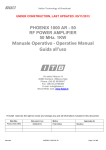
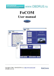
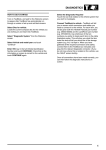
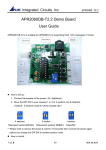
1
MPCProg 5xx
Manuale operativo - User manual
pag. 16 di
49
BOSCH EDC16/EDC16+/ME9
BOSCH EDC16/EDC16+/ME9 Identificare la zona dove sono poste le piazzole dove
andremo a saldare il connettore. Le piazzole sono situate in tutte le centraline Bosch
nella
parte
inferiore
della
centralina
BOSCH EDC16/EDC16+/ME9
Procedure of recognition and connection to the Bosch EDC16/EDC16+/ME9 ECUs
Identify the zone where we will go to bind the connector.
The pads are situated in all the Bosch ECU in the inferior part of the ECU, like easily we can see from the picture.
MPCProg 5xx
Manuale operativo - User manual
Di queste 14 piazzole noi utilizzeremo le prime 10 a sinistra.
Of those 14 pads we'll use the first 10 at left.
pag. 17 di
49
MPCProg 5xx
Manuale operativo - User manual
Saldatura degli strip
Stagnare solo ed esclusivamente il quinto pad partendo da sinistra della prima fila.
Weld exclusively the fifth pad from left of the first line.
pag. 18 di
49
MPCProg 5xx
Manuale operativo - User manual
pag. 19 di
49
Piazzare lo strip a cinque pin in modo corretto e cominciare la saldatura partendo dalla piazzola precedentemente
stagnata.
Stagnare e saldare tutti i pins. Assicurarsi che non vi siano corto-circuiti o palline di stagno tra le piste.
Place the strip to five pin in correct manner to begin the welding starting from the platform previously stagnated. Weld
all of the pins. Ensure that the pads are not short-circuits themselves or remaining of pond between the tracks.
MPCProg 5xx
Manuale operativo - User manual
Ripetere
l'intera
procedura
per
il
secondo
strip
cercando
di
mantenere
un
corretto
pag. 20 di
allineamento.
Repeat the whole procedure for the second strip wanting to maintain a correct alignment
49
MPCProg 5xx
Manuale operativo - User manual
pag. 21 di
49
Collegamento del connettore
La banda colorata che identifica il pin numero uno DEVE essere rivolta verso sinistra ( piazzola uno )
In caso di errore è possibile danneggiare irrimediabilmente la centralina.
CMD Technologies non si assume alcuna responsabilità in caso di errato collegamento.
Connector's connection
The colored band that identifies the pin number one should be revolted at left (pad one)
In case of mistake it is possible to damage the ECU.
CMD Technologies it is not taking responsibility in case of wandered connection.
MPCProg 5xx
Manuale operativo - User manual
pag. 22 di
49
DELPHI Ford/Jaguar/Ssangyong
DELPHI Ford/Jaguar/Ssangyong Identificare la zona dove sono poste le piazzole dove
andremo a saldare il connettore. Le piazzole sono situate in tutte le centraline DELPHI nella parte
inferiore sinistra della centralina Piazzare lo strip a cinque pin in modo corretto e cominciare la .
Stagnare e saldare tutti i pins.
Assicurarsi che non vi siano corto-circuiti o palline di stagno tra le piste. Vedi procedura EDC16
In questa centralina le mappe sono contenute all'interno della flash del Micro
DELPHI Ford/Jaguar/Ssangyong
Procedure of recognition and connection to the DELPHI Ford/Jaguar/Ssangyong
Identify the zone where we will go to bind the connector.
The pads are situated in all the DELPHI ECU in the left inferior part of the ECU, like easily we can see from the
picture.
Place the strip to five pin in correct manner to begin the welding starting from the platform previously stagnated.
Weld all of the pins. Ensure that the pads are not short-circuits themselves or remaining of pond between the tracks.
(see EDC16 description )
In this Ecu the Maps are into the Microprocessor Flash Memory
MPCProg 5xx
Manuale operativo - User manual
pag. 23 di
49
Collegare l'adattatore "DELPHI-MOTOROLA" come mostrato in figura. Ripettare la posizione del pin n°1.
Cavo piatto : la banda colorata che identifica il pin numero uno DEVE essere rivolta verso sinistra
(piazzola uno )
In caso di errore è possibile danneggiare irrimediabilmente la centralina. CMD Technologies non si assume
alcuna responsabilità in caso di errato collegamento.
Connect the "DELPHI-MOTOROLA" socket as showed in the picture. Pay attection at the position of pin n°1 .
Flat cable: the colored band that identifies the pin number one should be revolted at left (pad one)
In case of mistake it is possible to damage the ECU.
CMD Technologies it is not taking responsibility in case of wandered connection.
MPCProg 5xx
Manuale operativo - User manual
pag. 24 di
49
Alimentazione:
Per questa centralina non è necessario collegare il trasformatore al programmatore.
Dopo aver effettuato la connessione dei cavi ricollegare la centralina al cablaggio della vettura, avviare l'applicativo
MPCProg, girare il quadro su on, cliccare sul tasto +12Von, procedere alla lettura/programmazione. Per lo
scollegamento procedere nell'ordine inverso.Nel caso in cui si volesse alimentare al banco la centralina, collegare
l'alimentazione come descritto
PIN 1 GND
PIN 4 +12Vcc
Dopo aver effettuato la connessione dei cavi , avviare l'applicativo MPCProg, dare alimentazione al sistema , cliccare
sul tasto +12Von, procedere alla lettura/programmazione. Per lo scollegamento procedere nell'ordine inverso.
Si raccomanda di utilizzare un alimentatore stabilizzato.
Power supply:
For this ECU it is not necessary to connect the transformer to the programmer. Connect the pins , the adapter and the
MpcProg. Reconnect the ECU to the wiring of the car, start the application MPCProg, turn the dashboard key on, press
+12Von, proceed into read/write/checksum operations. For the disconnection proceed in the inverse order. If you
want to reprogram disconnected from the car, connect the power supply wires as showed in picture
PIN 1 GND
PIN 4 +12Vcc
Start the MPCProg application, give feeding to the system, press the +12Von button , proceed into
read/write/checksum operations. For the disconnection proceed in the inverse order.
It is recommended to use a stabilized local power source.
MPCProg 5xx
Manuale operativo - User manual
pag. 25 di
49
MARELLI MJET/MJET+ Fiat/Opel/Suzuki
MARELLI MJET/MJET+ Fiat/Opel/Suzuki Identificare la zona dove sono poste le piazzole dove
andremo a saldare il connettore. Le piazzole sono situate in tutte le centraline MARELLI nella parte
inferiore sinistra della centralina
MJET In questa centralina le mappe sono contenute all'interno della flash del Micro
MJET+ M58W016 In questa centralina le mappe sono contenute all'interno della flash M58W016
MARELLI MJET/MJET+ Fiat/Opel/Suzuki
Procedure of recognition and connection to MARELLI MJET Fiat/Opel/Suzuki
Identify the zone where we will go to bind the connector.
The pads are situated in all the MARELLI ECU in the left inferior part of the ECU, like easily we can see from the
picture.
MJET In this Ecu the Maps are inside the Microprocessor Flash Memory
MJET+ M58W016 In this Ecu the Maps are inside the M58W016 Flash Memory
MPCProg 5xx
Manuale operativo - User manual
MJET
Rimuovere la resistenza da 0 ohm come indicato e saldare i due pettini passo 1.27". (2 X 6 pins )
Non è necessario risaldare la resistenza dopo l'operazione.
Remove the 0 ohm resistor and weld the two 1.27" pins strips. (2 X 5 pins ) It's not
necessary ti put in place again the 0 ohm resistor after the reprogram operations.
MJET+ M58W016
pag. 26 di
49
MPCProg 5xx
Manuale operativo - User manual
pag. 27 di
49
Collegare l'adattatore "MARELLI MJET" come mostrato in figura. Ripettare la posizione del pin n°1.
Cavo piatto : la banda colorata che identifica il pin numero uno DEVE essere rivolta verso sinistra
(piazzola uno )
In caso di errore è possibile danneggiare irrimediabilmente la centralina. CMD Technologies non si
assume alcuna responsabilità in caso di errato collegamento.
Connect the "MARELLI" socket as showed in the picture. Pay attection at the position of pin n°1 .
Flat cable: the colored band that identifies the pin number one should be revolted at left (pad one)
In case of mistake it is possible to damage the ECU.
CMD Technologies it is not taking responsibility in case of wandered connection.
MPCProg 5xx
Manuale operativo - User manual
pag. 28 di
49
Alimentazione:
Per questa centralina non è necessario collegare il trasformatore al programmatore.
Dopo aver effettuato la connessione dei cavi ricollegare la centralina al cablaggio della vettura, avviare l'applicativo
MPCProg, girare il quadro su on, cliccare sul tasto +12Von, procedere alla lettura/programmazione. Per lo
scollegamento procedere nell'ordine inverso.Nel caso in cui si volesse alimentare al banco la centralina, collegare
l'alimentazione come descritto
PIN 1 GND
PIN 50,23 +12Vcc
Dopo aver effettuato la connessione dei cavi , avviare l'applicativo MPCProg, dare alimentazione al sistema , cliccare
sul tasto +12Von, procedere alla lettura/programmazione. Per lo scollegamento procedere nell'ordine inverso.
Si raccomanda di utilizzare un alimentatore stabilizzato.
Power supply:
For this ECU it is not necessary to connect the transformer to the programmer. Connect the pins , the adapter and the
MpcProg. Reconnect the ECU to the wiring of the car, start the application MPCProg, turn the dashboard key on, press
+12Von, proceed into read/write/checksum operations. For the disconnection proceed in the inverse order. If you
want to reprogram disconnected from the car, connect the power supply wires as showed in picture
PIN 1 GND
PIN 50,23 +12Vcc
Start the MPCProg application, give feeding to the system, press the +12Von button , proceed into
read/write/checksum operations. For the disconnection proceed in the inverse order.
It is recommended to use a stabilized local power source.
MPCProg 5xx
Manuale operativo - User manual
pag. 29 di
49
SIEMENS 5WS-803(A) Volvo s40v50 2.0d/Ford
C.Max 2.0d/ Peugeot 2.0 Hdi FAP
SIEMENS 5WS Volvo s40v50 2.0d/Ford C.Max 2.0d/ Peugeot 2.0 Hdi FAP Identificare la zona
dove sono poste le piazzole dove andremo a saldare il connettore. Le piazzole sono situate in tutte le
centraline Siemens 5WS nella parte inferiore sinistra della centralina.
In questa centralina le mappe sono contenute all'interno della flash del Micro ( solo sid803 con 29bl803)
SIEMENS 5WS Volvo s40v50 2.0d/Ford C.Max 2.0d/ Peugeot 2.0 Hdi FAP
Procedure of recognition and connection to Siemens 5WS Identify the zone where we will go to bind the
connector. The pads are situated in all the Siemens 5WS in the left inferior part of the ECU, like easily we can see
from
the
picture.
In this Ecu the Maps are into the Microprocessor Flash Memory ( only sid803 with 29bl803 )
MPCProg 5xx
Manuale operativo - User manual
Saldare i due pettini passo 1.27". (2 X 5 pins )
Weld the two 1.27" pins strips. (2 X 5 pins )
pag. 30 di
49
MPCProg 5xx
Manuale operativo - User manual
pag. 31 di
49
Collegare l'adattatore "SIEMENS" come mostrato in figura. Ripettare la posizione del pin n°1.
Cavo piatto : la banda colorata che identifica il pin numero uno DEVE essere rivolta verso sinistra
(piazzola uno )
In caso di errore è possibile danneggiare irrimediabilmente la centralina. CMD Technologies non si
assume alcuna responsabilità in caso di errato collegamento.
Connect the "SIEMENS" socket as showed in the picture. Pay attection at the position of pin n°1 .
Flat cable: the colored band that identifies the pin number one should be revolted at left (pad one)
In case of mistake it is possible to damage the ECU.
CMD Technologies it is not taking responsibility in case of wandered connection.
MPCProg 5xx
Manuale operativo - User manual
pag. 32 di
49
Alimentazione:
Per questa centralina non è necessario collegare il trasformatore al programmatore.
Dopo aver effettuato la connessione dei cavi ricollegare la centralina al cablaggio della vettura, avviare l'applicativo
MPCProg, girare il quadro su on, cliccare sul tasto +12Von, procedere alla lettura/programmazione. Per lo
scollegamento procedere nell'ordine inverso.Nel caso in cui si volesse alimentare al banco la centralina, collegare
l'alimentazione come descritto
Connettore 2
PIN G4 +12Vcc
Connettore 3
PIN C3 +12Vcc
PIN H4 GND
Dopo aver effettuato la connessione dei cavi , avviare l'applicativo MPCProg, dare alimentazione al sistema , cliccare
sul tasto +12Von, procedere alla lettura/programmazione. Per lo scollegamento procedere nell'ordine inverso.
Si raccomanda di utilizzare un alimentatore stabilizzato.
Power supply:
For this ECU it is not necessary to connect the transformer to the programmer. Connect the pins , the adapter and the
MpcProg. Reconnect the ECU to the wiring of the car, start the application MPCProg, turn the dashboard key on, press
+12Von, proceed into read/write/checksum operations. For the disconnection proceed in the inverse order. If you
want to reprogram disconnected from the car, connect the power supply wires as showed in picture
Connector 2
PIN G4 +12Vcc
Connector 3
PIN C3 +12Vcc
PIN H4 GND
Start the MPCProg application, give feeding to the system, press the +12Von button , proceed into
read/write/checksum operations. For the disconnection proceed in the inverse order.
It is recommended to use a stabilized local power source.
MPCProg 5xx
Manuale operativo - User manual
Rev. E del 27/11/2005
pag. 33 di
49
SIEMENS 5WK MS45 BMW Z4
SIEMENS 5WK MS45 BMW Z4 Identificare la zona dove sono poste le piazzole dove andremo a saldare il
connettore. Le piazzole sono situate in tutte le centraline Siemens 5WK MS45 nella parte centrale sinistra
della centralina Saldare i due pettini passo 1.27". (2 X 5 pins )
SIEMENS 5WK MS45 BMW Z4 Procedure of recognition and
connection to Siemens 5WK MS45 Identify the zone where we
will go to bind the connector.
The pads are situated in all the Siemens 5WK MS45 in the cetral left side of the ECU, like easily we can see from the
picture. Weld the two 1.27" pins strips. (2 X 5 pins )
MPCProg 5xx
Manuale operativo - User manual
pag. 34 di
49
Collegare l'adattatore "SIEMENS" come mostrato in figura. Ripettare la posizione del pin n°1.
Cavo piatto : la banda colorata che identifica il pin numero uno DEVE essere rivolta verso sinistra
(piazzola uno )
In caso di errore è possibile danneggiare irrimediabilmente la centralina. CMD Technologies non si
assume alcuna responsabilità in caso di errato collegamento.
Connect the "SIEMENS" socket as showed in the picture. Pay attection at the position of pin n°1 .
Flat cable: the colored band that identifies the pin number one should be revolted at left (pad one)
In case of mistake it is possible to damage the ECU.
CMD Technologies it is not taking responsibility in case of wandered connection.
MPCProg 5xx
Manuale operativo - User manual
pag. 35 di
49
Alimentazione:
Per questa centralina non è necessario collegare il trasformatore al programmatore.
Dopo aver effettuato la connessione dei cavi ricollegare la centralina al cablaggio della vettura, avviare l'applicativo
MPCProg, girare il quadro su on, cliccare sul tasto +12Von, procedere alla lettura/programmazione. Per lo
scollegamento procedere nell'ordine inverso.
Power supply:
For this ECU it is not necessary to connect the transformer to the programmer. Connect the pins , the adapter and the
MpcProg. Reconnect the ECU to the wiring of the car, start the application MPCProg, turn the dashboard key on, press
+12Von, proceed into read/write/checksum operations. For the disconnection proceed in the inverse order.
MPCProg 5xx
Manuale operativo - User manual
pag. 36 di
49
SIEMENS 5WS-201 Jaguar2.7D / Peugeot 2.7 Hdi /
LandRover 2.7D
SIEMENS 5WS-201 Jaguar2.7D / Peugeot 2.7 Hdi / LandRover 2.7D Identificare
la zona dove sono poste le piazzole dove andremo a saldare il connettore.
SIEMENS 5WS-201 Jaguar2.7D / Peugeot 2.7 Hdi / LandRover 2.7D
Procedure of recognition and connection to Siemens 5WS-201
Identify the zone where we will go to bind the connector.
MPCProg 5xx
Manuale operativo - User manual
Saldare i due pettini passo 1.27". (2 X 5 pins )
Weld the two 1.27" pins strips. (2 X 5 pins )
pag. 37 di
49
MPCProg 5xx
Rev. E del 27/11/2005
Manuale operativo - User manual
pag. 38 di
49
Collegare l'adattatore "SIEMENS" come mostrato in figura. Ripettare la posizione del pin n°1.
Cavo piatto : la banda colorata che identifica il pin numero uno DEVE essere rivolta verso sinistra
(piazzola uno )
In caso di errore è possibile danneggiare irrimediabilmente la centralina. CMD Technologies non si
assume alcuna responsabilità in caso di errato collegamento.
Connect the "SIEMENS" socket as showed in the picture. Pay attection at the position of pin n°1 .
Flat cable: the colored band that identifies the pin number one should be revolted at left (pad one)
In case of mistake it is possible to damage the ECU.
CMD Technologies it is not taking responsibility in case of wandered connection.
MPCProg 5xx
Manuale operativo - User manual
Rev. E del 27/11/2005
pag. 39 di
49
Alimentazione:
Per questa centralina non è necessario collegare il trasformatore al programmatore.
Dopo aver effettuato la connessione dei cavi ricollegare la centralina al cablaggio della vettura, avviare l'applicativo
MPCProg, girare il quadro su on, cliccare sul tasto +12Von, procedere alla lettura/programmazione. Per lo
scollegamento procedere nell'ordine inverso.Nel caso in cui si volesse alimentare al banco la centralina, collegare
l'alimentazione come descritto
Connettore 3
PIN K4 +12Vcc
PIN K3 +12Vcc
PIN M1 GND
Dopo aver effettuato la connessione dei cavi , avviare l'applicativo MPCProg, dare alimentazione al sistema , cliccare
sul tasto +12Von, procedere alla lettura/programmazione. Per lo scollegamento procedere nell'ordine inverso.
Si raccomanda di utilizzare un alimentatore stabilizzato.
Power supply:
For this ECU it is not necessary to connect the transformer to the programmer. Connect the pins , the adapter and the
MpcProg. Reconnect the ECU to the wiring of the car, start the application MPCProg, turn the dashboard key on, press
+12Von, proceed into read/write/checksum operations. For the disconnection proceed in the inverse order. If you
want to reprogram disconnected from the car, connect the power supply wires as showed in picture
Connettor 3
PIN K4 +12Vcc
PIN K3 +12Vcc
PIN M1 GND
Start the MPCProg application, give feeding to the system, press the +12Von button , proceed into
read/write/checksum operations. For the disconnection proceed in the inverse order.
It is recommended to use a stabilized local power source.
MPCProg 5xx
Manuale operativo - User manual
Rev. E del 27/11/2005
pag. 40 di
Bosch ME9.7 Mercedes Benz SLK 350
Identificare la zona dove sono poste le piazzole dove andremo a saldare il connettore.
Saldare i due pettini passo 1.27". (2 X 5 pins )
Identify the zone where we will go to bind the connector.
Weld the two 1.27" pins strips. (2 X 5 pins )
49
MPCProg 5xx
Manuale operativo - User manual
Rev. E del 27/11/2005
pag. 41 di
49
Collegare l'adattatore "Marelli" come mostrato in figura. Ripettare la posizione del pin n°1.
Cavo piatto : la banda colorata che identifica il pin numero uno DEVE essere rivolta verso sinistra
(piazzola uno )
In caso di errore è possibile danneggiare irrimediabilmente la centralina. CMD Technologies non
si assume alcuna responsabilità in caso di errato collegamento.
Connect the "Marelli" socket as showed in the picture. Pay attection at the position of pin n°1 .
Flat cable: the colored band that identifies the pin number one should be revolted at left (pad one)
In case of mistake it is possible to damage the ECU.
CMD Technologies it is not taking responsibility in case of wandered connection.
MPCProg 5xx
Manuale operativo - User manual
Rev. E del 27/11/2005
pag. 42 di
49
Alimentazione:
Per questa centralina non è necessario collegare il trasformatore al programmatore.
Dopo aver effettuato la connessione dei cavi ricollegare la centralina al cablaggio della vettura, avviare l'applicativo
MPCProg, girare il quadro su on, cliccare sul tasto +12Von, procedere alla lettura/programmazione. Per lo
scollegamento procedere nell'ordine inverso.Nel caso in cui si volesse alimentare al banco la centralina, collegare
l'alimentazione come descritto
Connettore Destro
PIN 15 +12Vcc
PIN 16 +12Vcc
PIN 2 GND
Dopo aver effettuato la connessione dei cavi , avviare l'applicativo MPCProg, dare alimentazione al sistema , cliccare
sul tasto +12Von, procedere alla lettura/programmazione. Per lo scollegamento procedere nell'ordine inverso.
Si raccomanda di utilizzare un alimentatore stabilizzato.
Power supply:
For this ECU it is not necessary to connect the transformer to the programmer. Connect the pins , the adapter and the
MpcProg. Reconnect the ECU to the wiring of the car, start the application MPCProg, turn the dashboard key on, press
+12Von, proceed into read/write/checksum operations. For the disconnection proceed in the inverse order. If you
want to reprogram disconnected from the car, connect the power supply wires as showed in picture
PIN 15 +12Vcc
PIN 16 +12Vcc
PIN 2 GND
Start the MPCProg application, give feeding to the system, press the +12Von button , proceed into
read/write/checksum operations. For the disconnection proceed in the inverse order.
It is recommended to use a stabilized local power source.
MPCProg 5xx
Manuale operativo - User manual
Rev. E del 27/11/2005
pag. 43 di
49
BOSCH BMSK BMW MOTORCYCLE
Identificare la zona dove sono poste le piazzole dove andremo a saldare il connettore. Le
piazzole sono situate in tutte le centraline Bosch nella parte inferiore della centralina
Piazzare lo strip a cinque pin in modo corretto e cominciare la saldatura partendo dalla piazzola
precedentemente stagnata.
Stagnare e saldare tutti i pins. Assicurarsi che non vi siano corto-circuiti o palline di stagno tra le piste.
Identify the zone where we will go to bind the connector.
The pads are situated in all the Bosch ECU in the inferior part of the ECU, like easily we can see from the
picture. Place the strip to five pin in correct manner to begin the welding starting from the platform previously
stagnated. Weld all of the pins. Ensure that the pads are not short-circuits themselves or remaining of pond
between the tracks.
MPCProg 5xx
Manuale operativo - User manual
SIEMENS MSV70 BMW
Rev. E del 27/11/2005
pag. 44 di
49
MPCProg 5xx
Manuale operativo - User manual
SIEMENS MSS65 BMW
Rev. E del 27/11/2005
pag. 45 di
49
MPCProg 5xx
Manuale operativo - User manual
Siemens SIM266 Mercedes
Rev. E del 27/11/2005
pag. 46 di
49
MPCProg 5xx
Manuale operativo - User manual
SIEMENS PPD1.1 VAG
Rev. E del 27/11/2005
pag. 47 di
49