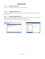
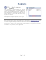
1
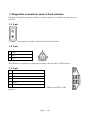
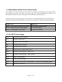
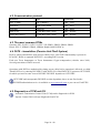
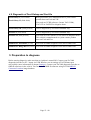
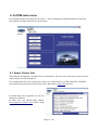
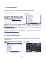
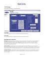
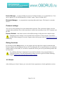
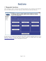
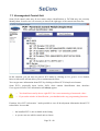
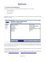
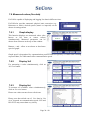
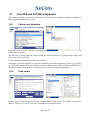
FoCOM
User manual
Copyright © 2004 – 2014 SECONS s.r.o., http://www.secons.com/
All rights reserved.
Page 2 / 40
SECONS s.r.o. is not connected with Ford Motor Company in any way.
Please read carefully this user manual before using the FoCOM application.
Before using the software please read license agreement.
Ford, Lincoln, Mercury are registered trademarks of Ford Motor Company or other owners.
Mazda is registered trademark of Mazda Motor Company or other owners.
Jaguar, Aston Martin, Land Rover are registered trademarks of Ford Motor Company or other
owners.
All trademarks used in this documentation or programs or any other material are used nominatively
for identification purposes only and may be property of their respective owners.
Page 3 / 40
Table of Contents
1 Introduction......................................................................................................................................6
1.1 Key features..............................................................................................................................6
1.2 Software updates.......................................................................................................................6
2 FoCOM software and driver installation..........................................................................................7
2.1 Microsoft Windows operating System......................................................................................7
2.2 Microsoft Windows 8 driver installation..................................................................................8
2.3 GNU/Linux System..................................................................................................................9
2.3.1 Requirements....................................................................................................................9
2.3.2 Setting up devices.............................................................................................................9
2.3.3 Installation.........................................................................................................................9
3 Diagnostic connectors used in Ford vehicles.................................................................................10
3.1 2-pin........................................................................................................................................10
3.2 3-pin........................................................................................................................................10
3.3 6-pin........................................................................................................................................10
3.4 OBD-I.....................................................................................................................................11
3.5 OBD-II....................................................................................................................................11
4 Information about Ford control units.............................................................................................12
4.1 Ford ECU terminology...........................................................................................................12
4.2 Communication protocol........................................................................................................13
4.3 The most common PCMs.......................................................................................................13
4.4 PATS – Immobilizer (Passive Anti-Theft System).................................................................13
4.5 Diagnostics of TCM and ICU.................................................................................................13
4.6 Diagnostic of Ford Galaxy and Ford Ka.................................................................................14
5 Preparation to diagnose..................................................................................................................14
6 FoCOM main menu........................................................................................................................15
6.1 Select Control Unit.................................................................................................................15
6.2 Auto-scan................................................................................................................................16
6.3 Special Diagnostics.................................................................................................................17
6.4 OBD-II Connector Location...................................................................................................17
6.5 Settings....................................................................................................................................18
6.6 About.......................................................................................................................................19
7 Diagnostic functions.......................................................................................................................20
7.1 Unrecognized Control Unit.....................................................................................................21
7.2 Control Unit Identification......................................................................................................23
7.3 Read fault code memory.........................................................................................................24
7.4 Freeze frame...........................................................................................................................24
7.5 Clear Fault Codes....................................................................................................................24
7.6 Measured values (live data)....................................................................................................25
7.6.1 Graph display..................................................................................................................25
7.6.2 Display 3x3.....................................................................................................................25
7.6.3 Display list......................................................................................................................25
7.6.4 Save to log.......................................................................................................................26
7.7 Actuators activation................................................................................................................27
7.7.1 Key On Engine Off test (KOEO test).............................................................................27
7.7.2 Key On Engine Running test (KOER test).....................................................................27
7.8 Programming/Coding functions..............................................................................................29
7.8.1 PATS (immobilizer) coding and ECU pairing.................................................................29
7.8.2 Diesel injector coding / pump adjustment.......................................................................30
7.8.3 Diesel DPF regeneration.................................................................................................30
7.8.4 Odometer adjustment......................................................................................................30
7.8.5 Reset ECU.......................................................................................................................30
8 Control unit configuration..............................................................................................................31
9 Control unit memory programming................................................................................................32
10 Ford IDS and FoCOM comparison..............................................................................................33
10.1 Control unit selection............................................................................................................33
10.2 Fault codes............................................................................................................................33
10.3 Identification.........................................................................................................................34
10.4 Measured values (Datalogger)..............................................................................................34
10.5 Actuator activation................................................................................................................35
10.6 Programming function..........................................................................................................35
10.7 Autoscan (Network test).......................................................................................................35
11 Reporting bugs and improvement requests...................................................................................36
11.1 How to create Debug Log.....................................................................................................36
11.2 How to create ecu Snapshot..................................................................................................37
12 Known problems..........................................................................................................................38
1 Introduction
Thank you for purchasing the FoCOM diagnostic interface and software. FoCOM is professional
tools for diagnostics of Ford vehicles. Please read carefully this User Manual before using the
product. If you have experience with original diagnostic tool Ford IDS, we recommend you to study
chapter comparing both systems .
We hope you'll find our products useful. In case you have any questions, problems or feedback
please contact as at [email protected]. We're here to help!
1.1 Key features
•
•
•
•
•
•
•
•
•
•
•
•
•
FoCOM covers for wide range of ECUs and models.
Easy connection via smart multiplexing USB to OBD2 interface
Wide range of communication protocols and buses covered incl. J1850 PWM, ISO, CAN
Automatic ECU recognition
Automatic vehicle scan
ECU Identification
Fault code (DTC) reading
Fault code clearing
Measured values / live data
Live data recording
Diagnostic protocol printing
Actuator tests
Coding functions
• Control unit configuration
• Printing
• Logging
The FoCOM system works with Ford vehicles. It works as well with Ford subsidiaries vehicles
such as Mazda, Lincoln, Mercury, Jaguar, but without guarantee of 100% functionality. The rule of
thumb is: tasks related to fault code memory and identification are reliable everywhere, but
measured values and other functions may not be fully supported.
1.2 Software updates
Updates of purchased software version are available for free download at
http://obdrus.ru/magazin/product/focom-ford-obd-scanner . User name = serial number of
FoCOM diagnostic interface.Password leave blank. The serial number can be found on a
silver label of the interface or insettings of FoCOM after performing “Test interface”. We
recommend you to install updated versionat least once a month, because updates provide support
for new ECUs and fix various issues.
Page 6 / 40
We recommend you to update firmware in diagnostic interface by clicking on Settings → Upgrade
firmware every time you update the software.
Page 7 / 40
2 FoCOM software and driver installation
2.1 Microsoft Windows operating System
1. Insert FoCOM installation CD to your CD-ROM drive
2. Run installation file FoComSetup.exe
3. Choose language for the installer
4. Choose your destination folder for the FoCOM and click on Install button and after
successful installation click on Close button.
FoCOM drivers are automatically updated during the FoCOM installation. When prompted to
install „unsigned“ drivers, click on Install this driver software anyway (Microsoft® Windows® 7)
or Continue Anyway (Microsoft® Windows® XP. ).
Microsoft® Windows® will automatically install drivers when you plug-in the FoCOM to USB
port. Driver installation isn't required for operation on GNU/Linux system.
Page 8 / 40
2.2 Microsoft Windows 8 driver installation
In case of problem with installing drivers on Windows 8 64-bit, please follow these steps:
1. Press Windows Key + R
2. In the window that appears, type: “shutdown.exe /r /o /f /t 00”
3. Press "OK" button
4. The System will restart to a "Choose an option" screen
5. Select "Troubleshoot" from "Choose an option" screen
6. Select "Advanced options" from "Troubleshoot" screen
7. Select "Windows Startup Settings" from "Advanced options" screen
8. Click on "Restart" button
9. System will restart to "Advanced Boot Options" screen
10. Select "Disable Driver Signature Enforcement" (press number on keyboard for option shown on
screen)
11. Once the system starts, install the diagnostic interface drivers as you would on Windows 7
Windows Vista & 7 required signed all .sys files (we use usbser.sys shipped by Microsoft
with valid digital signature). Final version of Windows 8 requires also signed .inf file (which
is not in our case). The above procedure helps to override unsigned .inf file. Once driver is
installed, the program will work properly.
Page 9 / 40
2.3 GNU/Linux System
Our diagnostic application are tested to work under Linux. The applications can be run
under Linux, BSD or Apple OS/X on Intel x86 using Wine environment. The installer and
applications perform fully automated installation under these operating system.
2.3.1
Requirements
• Linux 2.6.x with USB support (or FreeBSD)
• USB CDC Driver
• Wine 1.0.1
Recent Debian Linux or Ubuntu meet the above requirements.
2.3.2
Setting up devices
Driver installation isn't required for operation on GNU/Linux system. Diagnostic
applications require access to /dev/ttyACMx devices from Wine environment. This can be set-up
very easily using these commands:
ln
ln
ln
ln
-s
-s
-s
-s
/dev/ttyACM0
/dev/ttyACM1
/dev/ttyACM2
/dev/ttyACM3
~/.wine/dosdevices/com5
~/.wine/dosdevices/com6
~/.wine/dosdevices/com7
~/.wine/dosdevices/com8
Diagnostic interface should be then visible from the FoCOM diagnostic application.
2.3.3
Installation
Programs can be installed by launching setup .exe file using wine, e.g. wine FoCOMSetup.exe.
Page 10 / 40
3 Diagnostic connectors used in Ford vehicles
Location of diagnostic connector (database of vehicle images) is available from main menu of
FoCOM.
3.1 2-pin
Is used only for diagnostics of older vehicles by DCL/CART protocol.
3.2 3-pin
1
GND
2
DCL
3
DCL
This connector is used only for diagnostics of older vehicles by DCL/CART protocol.
3.3 6-pin
1
2
3
4
5
GND
6
This connector is used only for diagnostics of older vehicles using DCL/CART
protocol.
Page 11 / 40
3.4 OBD-I
1
9
2
10
Ford DCL Bus +
3
11
Chassis ground (GND)
4
12
Signal ground (GND)
5
13
6
14
7
15
8
16
ISO9141 K Line
Ford DCL Bus -
ISO9141 L-Line
This connector is used only for diagnostic of older vehicles by DLC protocol, connector is
compatible with OBD-II connector.
3.5 OBD-II
1
9
SAE J1850 Bus +
2
10
SAE J1850 Bus -
MS CAN High
3
11
MS CAN Low
Chassis ground (GND) 4
12
Signal ground (GND)
5
13
Flash. Pgm. Volt.
HS CAN High
6
14
HS CAN Low
ISO9141 K Line
7
15
ISO9141 L-Line
8
16
Diagnostic connector is mandatory in all vehicles after 2000, is used from 1996.
Page 12 / 40
4 Information about Ford control units
Every vehicle after 1996 contains at least one ECUs (Electronic Control Unit), powertrain control
unit (PCM) is present every time, in modern types also ABS, RCM(Airbag), perhaps even
IPC(Instrument Panel Cluster), BCM (Body Control Module) and many others.
Important notice for Jaguar diagnosis: due to differences and incompatibility between addressing
schemes used Jaguar and other FoMoCo vehicles some Jaguar ECUs may have different function.
FoMoCo ECU
Jaguar ECU
RPSDM – Rear passenger sliding door module
Heater module (Webasto heater)
ILCM – Illuminated Light Control Module
Tire Pressure Monitor
SASM – Steering angle sensor module
Passenger Seat Module
4.1 Ford ECU terminology
PCM
Powertrain Control Module
ICU
Injector Control Unit
TCM
Transmission Control Module
EPS
Electronic Power Steering
IPC
Instrument Panel Cluster
HEC
Hybrid Electric Cluster (same as IPC)
RCM
Restraint Control Module – airbags, etc.
ECS
Restraint Control Module – same as RCM
BCM
Body Control Module
GEM
General Electric Module
PATS
Immobilizer (Passive Anti-Theft System) – also part of PCM/BCM/IPC/RKE
RKE
Remote Keyless Entry
Page 13 / 40
4.2 Communication protocol
Protocol
Bus
Production
DCL (CART)
DCL (RS485)
1988 – 1996
Ford SCP
SAE J1850 PWM
1996 – 2005
Ford ISO
ISO9141
1996 – 2008
ISO 15765
CAN-BUS (ISO 11898)
2003 – present
UDS (ISO 14229)
CAN-BUS (ISO 11898)
2008 – present
4.3 The most common PCMs
Gasoline: EEC-IV, EEC-V, EEC-VI, EEC-VII, SIM21, SIM22, SIM24, SIM28
Diesel: EEC-V, SID802, SID803, SID804, Delphi, BOSCH EDC16
4.4 PATS – Immobilizer (Passive Anti-Theft System)
PATS is vehicle immobilizer used in Ford vehicles since 1998. PATS functionality is present in
PCM, IPC, BCM or separated PATS ECU, according PATS version.
Ford uses Texas Instruments or Texas Instruments Crypto transponders (vehicles since 2001).
Several generations of PATS are used.
Operations with PATS are authorized by timing access (delay before operation is allowed, so called
Timed PATS) or by entering INCODE (Coded PATS). For coded PATS ECU generates OUTCODE,
for which you need to enter correct INCODE. INCODE depends on OUTCODE
OUTCODE and consequently INCODE are time dependent, these are not fixed codes.
INCODE authorization service is available on www.patscode.com or you can use Ford ETIS.
4.5 Diagnostics of TCM and ICU
Automatic Transmission Control Unit (TCM) can be diagnosed via PCM.
Injector Control Unit is always diagnosed from PCM.
Page 14 / 40
4.6 Diagnostic of Ford Galaxy and Ford Ka
Ford Galaxy I (1995-2000)
Ford Galaxy II (2000-2006)
Both generations were manufactured as a joint venture
product between Ford and VW.
You need use VCDS software (former VAG-COM),
VAG1552 or VAS5052 to diagnose them.
Ford Galaxy III (2006-present)
Can be diagnosed by FoCOM in standard way.
Ford Ka I (1996-2008)
Can be diagnosed by FoCOM in standard way.
Ford Ka II (2008-present)
You need use Fiat Examiner or FiCOM or to diagnose them.
This vehicle is manufactured as a joint venture product
between Ford and Fiat.
Land Rover Freelander (97-06)
You need use BMW diagnostic tool such as BimCOM.
Land Rover Range Rover (94-05) You need use BMW diagnostic tool such as BimCOM.
5 Preparation to diagnose
Before starting diagnosis, make sure that car ignition is turned ON. Connect your FoCOM
diagnostic interface to PC / laptop via USB. Interface test in settings of FoCOM must pass
successfully (more information in chapter Settings). Connect your FoCOM diagnostic interface to
OBD-II connector in the vehicle. You can find the OBD-II connector using FoCOM OBD-II
Connector Location image database.
Page 15 / 40
6 FoCOM main menu
FoCOM main menu is divided into two parts → Vehicle diagnostics and Miscellaneous functions.
Descriptions of single functions are given below.
6.1 Select Control Unit
This function will display a complete list of control units. You can select and connect to the specific
control unit you wish to diagnose.
It is common that low-cost vehicles have only a few control units e.g. PCM, ABS, IPC and RCM.
All control units present in tested vehicle can be detected by Auto-scan function.
If control unit was recognized, you can use
diagnostic functions.
In other case, you should study chapter
Unrecognized Control Unit before using
diagnostic functions.
Page 16 / 40
6.2 Auto-scan
This function scans for all known
ECUs and shows the list of ECUs
present in vehicle along with number
of diagnostic trouble codes.
This function is identical
Network Test function in IDS.
with
Count of fault codes in auto-scan results is for some types of control units just approximate,
or may not be supported (then will be zero count displayed for each ECU).
Please always read relevant values using "Read Fault Code Memory" function after connecting to
each ECU.
Page 17 / 40
6.3 Special Diagnostics
Using special diagnostics you can perform the following special diagnostic tasks.
EEC-IV (DCL) Diagnostics – a diagnostics for
old EEC-IV control units used in Ford vehicles to
1996 (up to 1998 for Ford Escort).
Fuel Injection Pump Diagnostics – TDDI
Bosch PSG5 – diagnostic procedure described in
our manual “Ford Fuel Injection Pump (FIP)
coding” available at obdrus.ru
VW Ford Galaxy Diagnostics – special
diagnostics for Ford Galaxy produced by
Volkswagen to 2005.
High-Speed CAN BUS Analysis, Mid-Speed CAN BUS Analysis, SCP BUS Analysis – these
functions are described in our manual “CAN-BUS analysis information” available at
www.obdrus.ru
Recovery procedure (EECV/VI) – this function is used to recover control units after wrongly
performed flash programming.
Volvo ISO / CAN 2000 / CAN 2005 diagnostics – more information can be found at
obdrus.ru
6.4 OBD-II Connector Location
Using this database you can check a location of OBD-II connector in the vehicle. The database is
constantly updated.
Page 18 / 40
6.5 Settings
All functions in settings are described below.
Language
Choose language of FoCOM user interface in the drop down menu.
Units type
You can choose metric or imperial unit system for measured values.
Interface port selection
Refresh - this button refreshes COM port selection drop down list. Correct COM port number
should be already chosen after connecting diagnostic interface via USB to PC and clicking on
Refresh button. If not, choose correct COM port number from the list. It is needed in order to
perform successful interface test.
Test interface – before each use of program, please test proper function of your connected
interface by clicking this button. After successful test, you can see a serial number of your interface
displayed below the COM port field, then firmware version and information about active licenses.
Activate license – this button is used for activating new license/s to use the program or special
functions. Internet connection is required. Standard license is already activated for all interfaces
before purchase.
Page 19 / 40
Device Manager – is used to finding out correct COM port number, or to reinstall drivers. Your
device appears as “ELM-USB Interface (COMx)” under “Ports (COM & LPT)”.
Bluetooth Manager – is a preparation to upcoming bluetooth feature. The button is currently
inactive.
Protocol settings
You can set various timings for each communication protocol. This is advanced feature used for
example when problems occur with connection to control unit caused by slower ECU response and
the like.
Restore Defaults – this button restores all modified timings of all protocols to default values.
Changing protocol settings is not required before normal use of the program. You will be
asked to make changes by our tech. support when solving your issue at [email protected]
if necessary.
Debug functions
By clicking on Save Debug button, you can capture the latest data from elapsed communication
between control unit and program into one file. Providing this file is required only by our technical
support. Based on these data, we are able to monitor the whole process of performed operation and
its correctness.
Use of debug function is important for successful resolution of any program failure or
verifying its causes. For more information on how to proceed, please read the following
chapter #9.Reporting bugs and improvement requests.
6.6 About
After clicking on “About” button, you can read a license agreement or check application version.
Page 20 / 40
7 Diagnostic functions
After connecting to chosen control unit, the following diagnostic menu is displayed. The diagnostic
menu is divided into three parts. Basic functions, Advance functions and Expert functions.
If control unit was recognized, the diagnostic menu will be available immediately and you can use
diagnostic functions. If control unit wasn't identified uniquely, you should study next chapter
Unrecognized Control Unit before using diagnostic functions.
Page 21 / 40
7.1 Unrecognized Control Unit
Some Ford control units may do not return unique identification or FoCOM may not correctly
identify them. In such case is it necessary to choose the right type of the control unit from list.
In this situation, you can also use generic ECU mode by clicking on Use generic access button,
however this mode will not allow you to read measured values.
You can get more information about ECU by clicking on Show ECU Identification button.
Some ECUs (especially those before 2003) don't contain identification data, therefore
Unrecognized Control Unit information will always appear.
•
You should necessarily choose right ECU for correct measuring of measured values.
•
If you make mistake in identification, you shouldn't make any programming functions.
Function “Save ECU Information” make possible to save all development information about ECU
to hard disc. In case that:
– the installed ECU is not available in the listing
– or you are not sure which control unit to choose
Page 22 / 40
– or you wish to get the ECU automatically properly identified in next FoCOM version
– or you just want to help us to improve FoCOM
We will be more than happy to add support for any unsupported or unrecognized control unit to
next FoCOM version. We are usually able to do this within one or two working days based on so
called “ECU snapshot file”
From “Unrecognized ECU” window or “Control Unit Identification” window please choose “Save
ECU Information” button. When prompted if you want to perform fast or full snapshot please
choose “No” in order to make fast snapshot (fast snapshot takes less than one minute, full snapshot
may take up to 15 minutes for CAN-BUS ECUs or even longer for other communication protocols).
Please send the generated file(s) to [email protected]. For cars manufactured before 2004 we
will need also VIN code of the vehicle.
Page 23 / 40
7.2 Control Unit Identification
This function can display only identification data accessed by ECU, for example:
•
Identification data
•
ECU part number
•
serial number
Incomplete identification are very common mainly for older ECUs that do not provide full part
number or VIN code.
Each ECU should contain valid VIN code. If VIN is not supported, identification should display it.
If it isn't provided, you can program it in function ECU Programming/Coding, accessible from
menu Control Unit Diagnostics.
You can print identification by clicking on Print Identification button or you can copy to clipboard
by clicking on Copy Identification button.
Save ECU Information button is used to save “ECU snapshot” of tested control unit, as mentioned
in chapter “Unrecognized Control Unit” or “Reporting bugs and improvement requests”.
Page 24 / 40
7.3 Read fault code memory
This function allows to read and display diagnostic trouble codes saved in memory of control unit
(so called CMDTC).
Please note that some ECUs (mainly those used in Jaguar) do not support fault code reading at all.
Also ECUs that run in bootloader mode (e.g. the ECU is not properly programmed) do not allow
fault code reading. In such case, special message is displayed.
7.4 Freeze frame
Freeze frame displays conditions at first or last occurrence of currently selected fault code.
7.5 Clear Fault Codes
This function clears fault code stored in ECU memory.
Fault codes may appear immediately again if the related problem is not solved, or depending on
ECU conditions it might not be possible to clear fault codes (e.g. crash data in airbag will not allow
ECU to clear fault codes).
It is recommended to read memory by clicking on Re-read fault codes button again after clearing
the fault codes.
Page 25 / 40
7.6 Measured values (live data)
FoCOM is capable of displaying and logging live data in different views.
FoCOM also provides automatic physical unit conversion (e.g.
kilometers to miles), desired system (metric or imperial) can be
chosen in settings menu.
7.6.1
Graph display
This function displays two measured values (also
known as live data or sensor values)
simultaneously. Measured parameters can be
chosen from selectors at the top of the window.
Buttons + and – allow to accelerate or decelerate
speed of graph.
Graph speed is determined by communication protocol and how quickly is control unit returning
requested data, FoCOM cannot affect communication speed.
7.6.2
Display 3x3
For measuring 9 value simultaneously, click on
3x3 View button.
7.6.3
Display list
To measure all available values simultaneously,
click on List view button.
Please note values means slower refresh rate.
Please note that refresh rate of live data in “list
view” depends on communication speed. SCP and
ISO ECUs may return data very slowly.
Page 26 / 40
7.6.4
Save to log
Measured values can be saved/logged to a file by clicking on Start logging button. The logfile is
standard csv file and it is compatible with VagScope or can be imported to Microsoft Excel or
OpenOffice Calc.
Page 27 / 40
7.7 Actuators activation
This function is used activate actuators and perform tests (including KOEO and KOER) and various
actuator actions.
Some actuator tests may display detected fault codes at the end of the test.
Please note that most control units do not allow any specific actuators, only KOEO or KOER tests
(this limitation is present also in original dealer tester).
7.7.1
Key On Engine Off test (KOEO test)
KOEO is automated powertrain module test available on most EEC-V and EEC-VI control units.
The test must be performed on stopped engine with ignition key in ON position. The KOEO test
may require special actions such as turning steering wheel from minimum to maximum, pressing
brake and accelerator pedal. For vehicle-specific instructions please refer to Ford service manuals.
All problems that were detected during the test are displayed in form of fault codes at the end of
test. The test terminates automatically.
The KOEO test should be performed before running KOER test.
The KOEO test may affect self-learnt values present in keep-alive memory (KAM).
7.7.2
Key On Engine Running test (KOER test)
KOER is automated powertrain module test available on most EEC-V and EEC-VI control units.
The test must be performed running engine. The KOER test may require special actions such as
Page 28 / 40
turning steering wheel from minimum to maximum or pressing brake. For vehicle-specific
instructions please refer to Ford service manuals. All problems that were detected during the test are
displayed in form of fault codes at the end of test. The test terminates automatically.
The KOER test may affect self-learnt values present in keep-alive memory (KAM).
Page 29 / 40
7.8 Programming/Coding functions
This function allow you to e.g. programming VIN code, operate with immobilizer (PATS) or
programming calibration data of injectors.
Important notice: Some of the coding functions can not be run when the engine is running and vice
versa (some coding functions can not be run unless the engine is running). Some coding operations
require specific conditions or procedure to be performed. Please refer to vehicle manufacturer
technical service manuals for more information.
Please read carefully all manuals for specific coding operation. The manuals are available online
from our website, obdrus.ru
7.8.1
PATS (immobilizer) coding and ECU pairing
These functions are used to add/code new keys to a vehicle. More detailed description is available
in our PATS coding manual.
Page 30 / 40
7.8.2
Diesel injector coding / pump adjustment
FoCOM supports diesel injector classification coding and fuel pump adjustments on diesel PCM
control units where applicable. More detailed description is available in our Ford TDCi Injectors
coding manual.
7.8.3
Diesel DPF regeneration
FoCOM supports static/dynamic diesel particulate filter regeneration and reset options on diesel
PCM control units where applicable. More detailed description is available in our Ford DPF service
manual.
7.8.4
Odometer adjustment
This function is available in IPC control unit and is used to adjust mileage when replacing
odometer. FoCOM is capable of changing value up where instrument cluster supports this function.
In addition to the above function special paid module exists that allows changing odometer to any
desired value, on both new and used instrument cluster. More information about this paid function
is available at obdrus.ru
7.8.5
Reset ECU
This function is used to restart control unit (similar to battery/fuse disconnect). The function is
useful when recorded fault codes depend on functionality of another control unit(s) or after
changing central vehicle configuration.
Page 31 / 40
8 Control unit configuration
This function is under development. Until the function is available to the general public please use
“AS-BUILT” function in coding menu or central CCF configuration read/write function. For more
information please refer to FoCOM control unit configuration manual.
Page 32 / 40
9 Control unit memory programming
Flash and serial memory programming functionality will be available shortly in special FoCOM
programming module (flash programming is available to selected beta testers only, paid feature).
Page 33 / 40
10
Ford IDS and FoCOM comparison
This chapter describes comparison of functions of FoCOM with original Ford Motor Diagnostics
IDS (Integrated Diagnostic System).
10.1
Control unit selection
Main difference between concepts of program FoCOM and system IDS is in user approach to
vehicle and its systems.
The IDS uses so called Function system, which first chooses function (e.g. Read trouble codes) and
then control unit (e.g. PCM).
FoCOM chooses control unit first and then function.
Advantage of second approach is especially similarity with other diagnostic systems (e.g. VCDS,
etc.) and consequently more user friendly for those who have not much experience with IDS. Next
advantage is easier identification of concrete type of control unit for programming etc.
10.2
Fault codes
Reading and Clearing Diagnostic Trouble Codes acted like IDS system, all CMDTC (Continuous
Memory Diagnostic Trouble Codes) are read and clear from control unit.
Page 34 / 40
10.3
Identification
Ford IDS does not provide this function, however is possible to display some identification
information in Log Viewer – Technician View (Full Diagnostic).
FoCOM use special function for reading identification information.
10.4
Measured values (Datalogger)
Unlike IDS system the FoCOM implements three options of displaying measured values:
•
Graph – for comparison two measured values simultaneously in graph
•
Display 3x3 – appropriate for see display from longer distance
•
Display list – for display all available measured values
It isn't necessary to set vehicle equipment, which is sometimes hardly observable, FoCOM displays
all measured values, provided by control unit.
The FoCOM can sometimes display more values than IDS system, e.g. in Engine control unit is
commonly available distance moved from last clearing flash memory (this function isn't supported
in IDS system).
Page 35 / 40
10.5
Actuator activation
Actuator activation is implemented in same way like IDS system.
10.6
Programming function
Direct Flash / EEPROM programming functions are described in separate document and require
additional license.
10.7
Autoscan (Network test)
This function scans for all known ECUs, and shows the list of ECUs present in vehicle along with
number of diagnostic trouble codes, thus provide test of network.
Both functions Network Test (IDS) and Autoscan (FoCOM) are identical.
Page 36 / 40
11
Reporting bugs and improvement requests
Our customers can take advantage of our full technical support for free. In case you have any
difficulties with using FoCOM, do not hesitate to contact us directly at [email protected] or
through your distributor.
Please read carefully this chapter in order to provide us with all information so as we can resolve
your problem quickly.
Note:
Before sending support request for failing operation, please make sure you have met all
conditions required for the operation (e.g. you are entering correct data, correct engine
temperature for DPF regeneration, correct number of keys for engine start, etc).
Also please make sure you have the latest FoCOM version before reporting any issues.
In case of communication issues we recommend to check diagnostic plug connection and
retry procedure at least once, connection problems may result in erratic communication
issues.
In case you encounter to failure of any program functions (e.g. fault codes reading/clearing,
coding functions, actuator tests, connecting to ECU …), or you're missing some function or
some function does not work sufficiently, please prepare the following data in your email
before sending your request to our technical support:
1. Detailed description of failure or your improvement request
2. Vehicle description - VIN code, model, manufacture year, engine type
3. Attach Debug Log (in case that required function doesn't work properly). This file captures
data from the latest communication between program and ECU, so we can detect failure
causes.
4. Attach Snapshot of tested ECU – this file contains important information about tested
control unit.
11.1
How to create Debug log file
It is necessary to perform operation that is not
working correctly first. Once failure occurs, go back
directly to settings in main menu (do not close the
program). Click on “Save Debug” button. Name and
save the file into well known directory in your
computer.
Page 37 / 40
Enable “Debug mode” check box only at our special request.
This function is used to tell program enable special functions in diagnostics interface and to log
more data than required for normal operation.
Page 38 / 40
11.2
How to create ecu
Snapshot
After connection to related control unit, click on
“Control Unit Identification”. In the following window
click on “Save ECU Information” button. Click on “No”
when asked whether you wish to save a full snapshot.
Choose a directory to save the file and confirm. Saving
may take a few minutes.
Full snapshots are required only at our special request.
Please send all support requests along with required data attached to [email protected]. Your
case will be assigned with unique ticket number in order to communicate efficiently with you.
Also feel free to contact us with any suggestions for improvements in the software on the same email address. Your feedback is greatly appreciated.
Page 39 / 40
12
Known problems
•
US Ford models 2011: PATS coding operations are not supported on some models
•
Connection to Japan-made ABS on Mazda 3 2006 may fail (this issue is related to one
specific ABS ECU)
•
EEC-IV (pre-1996 ECUs) DLC diagnostics may not return correct data on some ECUs.
Above problems will be resolved in future FoCOM updates.
Page 40 / 40