1
KD-1540P
482mm
19"
DIGITAL
USB
Catalog
Catalog......................................................................Page1
Safety Instructions......................................................Page2
KD-1540P Speaker Management...........................Page3~63
1
IMPORTANT SAFETY INSTRUCTIONS
Note: in order to ensure safety, please read these instructions carefully
All safety and operating instructions should be read before the
product is operated.
Attention:To reduce the risk of fire or electric shock, do not expose this apparatus
to rain or moisture!
6 Objects or liquid entry
1 Ventilation
inside the unit
Do not block any
ventilation openings.
Be careful that no
objects fall or liquid is
spilled inside the unit
through ventilation
openings.
2 Cleaning
Clean only with dry
cloth.
7 Humidity
The unit should far
away form water.
3 Heat sources
Do not install near any
heat sources such as
radiators, stoves, or
other apparatus that
produce heat.
8 Maintenance
Refer all servicing to
qualified service
personnel. To prevent
the risk of shock, do
not attempt to service
this equipment
yourself because
opening or removing
covers may expose
you to
dangerous voltage or
other hazards.
4 Power cord proctecion
Protect the power cord
from being walked on
or pinched particularly
at plugs.
5 Overload
Power plug should
not overload.
2
KD-1540P Digital Karaoke Processor
Quick User's Manual
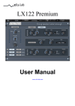
Referring to the front panel here below, the description of the KD-1540P functions with reference
to the control buttons and encoders.
Mic Jacks
Editing Section Controls
Effects, Microphones and Music fast Output Level Controls
●
Quick Edit Process Select
Getting Started
As soon as the KD-1540P is turned ON, on the LCD will appear in sequence the Device model
Name
Karaoke Multi-Effect
DSP Processor
and the Control Sw Version
Karaoke Effector
==== Software V3.30a ====
The KD-1540P is a Karaoke Processor allowing the user to control separately the processes related
to the Audio path, to the Microphone (Voice) path and to the Effects applied to the Microphone
path.
After the 2 previous screen shots, the last one will appear showing the last selected configuration,
in terms of Audio, Microphone, Effects, level status, Audio Key Shift and Selected Input setting for
the KD-1540P.
If the last configuration was i.e. “50%” level for the microphone, “60%” for the Audio, “30%” for
Effects, “No Key Shift” for the Audio and “Input A” as the selected Input, then the screen, which is
the “Normal Operation” screen, will be the following
: 50%
: 50%
C: 60%
S: 50%
3
Fx: 30%
InA
●
Editing Section Controls Use
The KD-1540P's Editing Section is equipped with 4 “Navigation” Buttons (Up, Down. L and R) and
2 more “EDIT” and “ENTER” buttons.
The unit is using these 6 buttons to access the several sub-menus allowing the unit's setting and
the Music, Mic and Efx functions editing.
In details, the button “EDIT” allows to enter the unit's sub-menus, if coming from the previously
described “Normal Operation” screen.
If already inside the editing menu, then the “EDIT” button will assume the function, if pressed, to
go back to the previous edited page...up to the function of exiting the Editing environment.
The button “ENTER” allows the user to access the several Sub-Menus of the Editing environment.
Once inside the several Sub-Menus (accessible “vertically” with the “ENTER” button) to scroll
“Horizontally” the several pages of the Sub-menus it is enough to use the buttons “L” and “R”.
Once visualized the pages containing the parameters to edit, it is possible to enter it again using
the “ENTER” button, then to change the parameters values using the “UP” and “DOWN” buttons or
to move from one editable parameter and an other one using again the “L” and “R” buttons
Starting from the “Normal Operation” screen coming after turning On the KD-1540P
: 50%
: 50%
C: 60%
S: 50%
Fx: 30%
InA
The sub-menus accessible thanks to the “MENU”, “ENTER”, “L”, “R”, “UP” and “DOWN” buttons,
are resumed by the following “trees” schemes, where the Main Menu is accessible from the
“Normal Operation” Screen just pressing the “MENU” button:
L/R Buttons
[to navigate between Sub menus]
MAIN MENU:......
Program Submenu
““
L/R Buttons
[to navigate between Sub menus Pages]
MENU
ENTER
EDIT
MAIN MENU:......
Load AllPreset Program
Program Submenu
Store AllPreset Program
Speed =
MENU
MENU
MENU
Program Submenu
Microphone
Mic Para Submenu
Kill Fdbk
60%
Microphone
Select =
Microphone
A: 8ms R:0.1s
UP/DOWN Buttons
[to change the selected parameters values]
Kill Fdbk
Type-A
NoiseGate
-80dB
ENTER
MENU
ENTER
Load AllPreset Program
01:
Preset 1 (up to) 08:
Store AllPreset Program
001: Preset 1 (up to) 08: Preset 8
EDIT
Microphone
ENTER
-> Speed =
EDIT
ENTER
EDIT
ENTER
Preset 8
Microphone
-> Select =
Kill Fdbk
0% (up to) 100%
Kill Fdbk
Type-A or Type-B
Microphone
NoiseGate
->A: 1ms (up to) 480ms R: 4.0s
R
A: 1ms R->0.1s (up to) 2.8s
R
-80dB
L
-80dB
L
A: 80ms R: 4.0s ->-90dB[Off] (up to) -65dB
EDIT
MENU
Microphone
HPF
59.5 Hz
Butwrth 12dB
ENTER
Microphone
HPF
-> 20Hz (up to) 20kHz
Butwrth 12dB
L
R
59.5Hz ->No Cut-Off (up to) Butwrth 24dB
4
L/R Buttons
[to navigate between Sub menus]
L/R Buttons
[to navigate between Sub menus Pages]
UP/DOWN Buttons
[to change the selected parameters values]
EDIT
MAIN MENU:......
MENU
Mic Para Submenu
Microphone
59.5 Hz
LPF
Butwrth 12dB
ENTER
Microphone
LPF
-> 20Hz (up to) 20kHz
Butwrth 12dB
L
R
59.5Hz ->No Cut-Off (up to) Butwrth 24dB
EDIT
MENU
““
Microphone
PEQ: 1 (to) 15
1.00kHz Q=1.00 +0.0dB
ENTER
Microphone
PEQ: -> 1 (up to) 15
20Hz
Q=1.00 +0.0dB
->
L
R
20Hz (up to) 20kHz
Q=1.00
L
R
20Hz -> Q=3.0 (up to) 32.5
20Hz
Microphone
1.00kHz
LoShelv
+0.0dB
----
EDIT
ENTER
Q=1.00
LoShelv
+0.0dB
----
->-12dB (up to) -+12dB
EDIT
MENU
Microphone
1.00kHz
HiShelv
+0.0dB
----
ENTER
Microphone
-> 20Hz (up to) 20kHz
----
HiShelv
+0.0dB
L
R
20Hz
““
----
L
R
““
->-12dB (up to) -+12dB
Microphone
-> 20Hz (up to) 20kHz
20Hz
+0.0dB
L
R
MENU
+0.0dB
----
->-12dB (up to) -+12dB
EDIT
MENU
Microphone
Compressor
A: 80ms R:1.0s 2:1 -16
ENTER
Microphone
Compressor
->A: 1ms (up to) 480ms R: 1.0s 2:1 -16
L
R
A: 80ms R->0.1s (up to) 2.8s 2:1 -16
L
R
A: 80ms R: 1.0s->1:1 (up to) 20:1 -16
L
R
A: 80ms R: 1.0s 2:1->-24 (up to) +0
““
““
EDIT
MENU
Microphone
Compressor
Knee : Soft
ENTER
Microphone
Compressor
->
Knee : Soft (up to) Hard
EDIT
MENU
Microphone
In: +3dB
CompVol
Out: +0.0dB
ENTER
Microphone
-> In: -6.0dB (up to) +6dB
L
R
In: +3dB
CompVol
Out : +0.0dB
-> Out :-6.0dB (up to) +6dB
The ALL parameter accessible within the MIC PARA SUBMENU, can be quickly accessed
without entering the MAIN MENU, just pressing the “MIC” button on the front panel in
the EDIT section.
L/R Buttons
[to navigate between Sub menus]
MAIN MENU:......
Effect Para Submenu
““
““
L/R Buttons
[to navigate between Sub menus Pages]
MENU
ENTER
MENU
MENU
Effect
Left Time :
Delay
680 mS
UP/DOWN Buttons
[to change the selected parameters values]
EDIT
ENTER
Effect
-> Left Time :
Delay
0 mS (up to) 680mS
EDIT
Effect
Lft Feedback :
Delay
0%
ENTER
Effect
-> Left Feedback :
Delay
0% (up to) 100%
EDIT
Effect
Right Time :
Delay
680 mS
5
ENTER
Effect
-> Right Time :
Delay
0 mS (up to) 680mS
MENU
““
MENU
““
MENU
““
MENU
““
MENU
““
MENU
““
MENU
““
MENU
““
MENU
““
MENU
““
MENU
““
EDIT
Effect
Delay
Right Feedback : 0%
ENTER
Effect
-> Right Feedback :
Delay
0% (up to) 100%
EDIT
Effect
Center Time :
Delay
680 mS
ENTER
Effect
-> Center Time :
Delay
0 mS (up to) 680mS
EDIT
Effect
Delay
Center Feedback : 0%
ENTER
Effect
-> Center Feedback :
Delay
0% (up to) 100%
EDIT
Effect
Left Pan Left:
Delay
100%
ENTER
Effect
-> Left Pan Left:
Delay
0% (up to) 100%
EDIT
Effect
Left Pan Right:
Delay
0%
ENTER
Effect
Right Pan Left:
Delay
0%
ENTER
Effect
-> Left Pan Right:
Delay
0% (up to) 100%
Effect
-> Right Pan Left:
Delay
0% (up to) 100%
EDIT
EDIT
Effect
Delay
Right Pan Right: 100%
ENTER
Effect
-> Right Pan Right:
Delay
0% (up to) 100%
Effect
-> Center Pan Left:
Delay
0% (up to) 100%
EDIT
Effect
Delay
Center Pan Left:
50%
ENTER
EDIT
Effect
Delay
Center Pan Right: 50%
ENTER
Effect
-> Center Pan Right:
Delay
0% (up to) 100%
EDIT
Effect
Direct Volume :
Delay
10%
ENTER
Effect
-> Direct Volume :
Delay
0% (up to) 100%
EDIT
Effect
Delay
Direct
ENTER
Effect
PreDelay :
100mS
Delay
->Direct
PreDelay : 0mS (up to) 150mS
MENU
no
““
Volume:
EDIT
Effect
Delay
Percent
MENU
Delay
->Percent
EDIT
Effect
Out Volume:
Delay
40%
Effect
Decay :
Reverb
70%
Effect
Reverb
PreDelay Time : 80mS
Effect
Density:
Delay
40%
MENU
ENTER
Effect
->
Decay :
Reverb
0% (up to) 100%
ENTER
Effect
-> PreDelay Time :
Reverb
0mS (up to) 80mS
ENTER
Effect
->
Density :
Reverb
0% (up to) 100%
EDIT
Effect
Reverb
Loop Highpass : 20.0 Hz
ENTER
Effect
Reverb
-> Loop Highpass : 20.0 Hz (up to) 20.0kHz
EDIT
MENU
““
Delay
0% (up to) 100%
EDIT
MENU
““
Effect
->
Out Volume:
EDIT
MENU
““
ENTER
EDIT
EDIT
““
Effect
Reverb
Loop Lowpass : 20.0kHz
ENTER
Effect
Output HDamp :
ENTER
Effect
Reverb
-> Loop Lowpass : 20.0 Hz (up to) 20.0kHz
EDIT
MENU
““
Effect
Volume: 60%
0% (up to) 100%
““
““
ENTER
Reverb
20.0kHz
6
Effect
-> Output HDamp :
Reverb
20.0 Hz (up to) 20.0kHz
L/R Buttons
[to navigate between Sub menus]
L/R Buttons
[to navigate between Sub menus Pages]
MENU
MAIN MENU:......
““
““
EDIT
Effect
Effect Para Submenu
MENU
MENU
Reverb
Output LDamp :
20.0 Hz
Effect
Density Predelay:
Reverb
10mS
Effect
Direct Volume :
Reverb
50%
Effect
Out Volume :
Reverb
50%
““
MENU
Effect
ENTER
Reverb
-> Output LDamp :
20.0 Hz (up to) 20.0kHz
EDIT
ENTER
Effect
Reverb
-> Density Predelay: 0mS (up to) 200mS
EDIT
MENU
““
UP/DOWN Buttons
[to change the selected parameters values]
ENTER
EDIT
ENTER
Effect
-> Direct Volume :
Reverb
0% (up to) 100%
Effect
->
Out Volume :
Reverb
0% (up to) 100%
EDIT
Effect
1.00kHz
DEL-PEQ: 1 (to) 3
Q=1.00 +0.0dB
ENTER
Effect
20Hz
Q=1.00
DEL-PEQ: -> 1 (up to) 3
+0.0dB
L
R
-> 20Hz (up to) 20kHz Q=0.05
+0.0dB
L
R
20Hz -> Q=0.05 (up to) 3.00
20Hz
+0.0dB
L
R
Q=1.00
->-15dB (up to) -+12dB
EDIT
““
MENU
Effect
1.00kHz
REV-PEQ: 1 (to) 3
Q=1.00 +0.0dB
ENTER
Effect
20Hz
Q=1.00
REV-PEQ: -> 1 (up to) 3
+0.0dB
L
R
-> 20Hz (up to) 20kHz Q=0.05
R
+0.0dB
L
20Hz -> Q=0.05 (up to) 3.00
R
20Hz
+0.0dB
L
Q=1.00
->-15dB (up to) -+12dB
The ALL parameter accessible within the EFFECT PARA SUBMENU, can be quickly
accessed without entering the MAIN MENU, just pressing the “EFFECT” button on the
front panel in the EDIT section.
L/R Buttons
[to navigate between Sub menus]
L/R Buttons
[to navigate between Sub menus Pages]
UP/DOWN Buttons
[to change the selected parameters values]
EDIT
MAIN MENU:......
Music Para Submenu
MENU
ENTER
Music
A: 8ms
NoiseGate
R:0.1s
ENTER
-80dB
Music
NoiseGate
->A: 1ms (up to) 480ms R: 4.0s
R
A: 1ms R->0.1s (up to) 2.8s
R
-80dB
L
-80dB
L
A: 80ms R: 2.0s ->-90dB[Off] (up to) -65dB
““
EDIT
MENU
Music
Semitone:
KeyShift
#
ENTER
Music
-> Semitone:
KeyShift
b12 (up to) #12
EDIT
MENU
““
Music
59.5 Hz
HPF
Butwrth 12dB
ENTER
Music
HPF
-> 20Hz (up to) 20kHz
Butwrth 12dB
L
R
59.5Hz ->No Cut-Off (up to) Butwrth 24dB
MENU
““
Music
59.5 Hz
LPF
Butwrth 12dB
EDIT
ENTER
Music
LPF
-> 20Hz (up to) 20kHz
Butwrth 12dB
L
R
59.5Hz ->No Cut-Off (up to) Butwrth 24dB
7
EDIT
MENU
““
Music
1.00kHz
PEQ: 1 (to) 15
Q=1.00 +0.0dB
ENTER
Music
20Hz
->
Q=1.00
PEQ: -> 1 (up to) 15
+0.0dB
L
R
20Hz (up to) 20kHz Q=3.0
20Hz -> Q=3.0 (up to) 32.5
Q=1.00
Music
1.00kHz
----
LoShelv
+0.0dB
ENTER
Music
-> 20Hz (up to) 20kHz
LoShelv
+0.0dB
----
->-12dB (up to) -+12dB
EDIT
MENU
Music
1.00kHz
----
HiShelv
+0.0dB
ENTER
Music
-> 20Hz (up to) 20kHz
----
HiShelv
+0.0dB
L
R
20Hz
““
----
L
R
20Hz
““
->-12dB (up to) -+12dB
EDIT
MENU
““
+0.0dB
L
R
20Hz
+0.0dB
L
R
----
->-12dB (up to) -+12dB
EDIT
MENU
Music
Compressor
A: 80ms R:1.0s 2:1 -16
ENTER
Music
Compressor
->A: 1ms (up to) 480ms R: 1.0s 2:1 -16
L
R
A: 80ms R->0.1s (up to) 2.8s 2:1 -16
L
R
A: 80ms R: 1.0s->1:1 (up to) 20:1 -16
L
R
A: 80ms R: 1.0s 2:1->-24 (up to) +0
““
““
EDIT
MENU
Music
Compressor
Knee : Soft
ENTER
Music
->
Compressor
Knee : Soft (up to) Hard
EDIT
MENU
Music
In: +3dB
CompVol
Out: +0.0dB
ENTER
Music
-> In: -6.0dB (up to) +6dB
L
R
In: +3dB
CompVol
Out : +0.0dB
-> Out :-6.0dB (up to) +6dB
The ALL parameter
accessible within the MUSIC PARA SUBMENU, can be quickly
accessed without entering the MAIN MENU, just pressing the “MUSIC” button on the
front panel in the EDIT section.
L/R Buttons
[to navigate between Sub menus]
MAIN MENU:......
MainOut Para Submenu
L/R Buttons
[to navigate between Sub menus Pages]
MENU
ENTER
UP/DOWN Buttons
[to change the selected parameters values]
EDIT
Music
A: 50%
SignalFrom
M: 50%
Efx: 50%
Music
ENTER
SignalFrom
->A: 0%(up to) 100% M: 50%
R
A: 50% M: 0%(up to) 100%
R
MENU
Efx: 50%
L
A: 50% M: 50%
““.
Efx: 50%
L
-> Efx: 0%(up to) 100%
EDIT
Music
1.00kHz
PEQ: 1 (to) 3
Q=1.00 +0.0dB
ENTER
Music
20Hz
->
Q=1.00
PEQ: -> 1 (up to) 3
+0.0dB
L
R
20Hz (up to) 20kHz Q=3.0 +0.0dB
R
L
20Hz -> Q=3.0 (up to) 32.5
R
20Hz
8
+0.0dB
L
Q=1.00
->-12dB (up to) -+12dB
MENU
““
Music
Delay
2.083mS
Delay =
EDIT
ENTER
Music
Delay =->
R
Delay =
L
0->000mS (up to) 979mS
EDIT
MENU
““
Delay
0.000mS (up to) 80.000mS
Music
Limiter
A: 1ms R:1.0s Ths: -16
ENTER
Music
Limiter
->A: 1ms (up to) 480ms R: 1.0s Ths: -16
L
R
A: 1ms R->0.1s (up to) 2.8s Ths: -16
L
R
A: 1ms R: 1.0s ->Ths: -30 (up to) +0
The ALL parameter accessible within the MAINOUT PARA SUBMENU, can be quickly
accessed without entering the MAIN MENU, just pressing the “MAIN” button on the
front panel in the EDIT section.
L/R Buttons
[to navigate between Sub menus]
MAIN MENU:......
Sub Para Submenu
L/R Buttons
[to navigate between Sub menus Pages]
MENU
ENTER
UP/DOWN Buttons
[to change the selected parameters values]
EDIT
Subwoofer
A: 50%
SignalFrom
M: 50%
Efx: 50%
Subwoofer
ENTER
SignalFrom
->A: 0%(up to) 100% M: 50%
R
A: 50% M: 0%(up to) 100%
R
Efx: 50%
L
A: 50% M: 50%
““
Efx: 50%
L
-> Efx: 0%(up to) 100%
EDIT
MENU
Subwoofer
Percent= 50%
Harmony
F=24-36Hz
ENTER
Subwoofer
-> Percent= 0% (up to) 50%
R
Harmony
F=24-36Hz
L
Percent= 50%
F=24-36Hz (up to) 36-56Hz
MENU
““
““
““
Subwoofer
Source
Source = L+R
Subwoofer
->
Source =
Source
L (up to) L+R
EDIT
MENU
Subwoofer
Polarity
Polarity = [ + ]
ENTER
Subwoofer
Polarity
->
Polarity = [ - ] (up to) [ + ]
EDIT
MENU
Subwoofer
HPF
59.5 Hz
Butwrth 12dB
ENTER
Subwoofer
-> 20Hz (up to) 20kHz
R
20Hz
HPF
Butwrth 12dB
L
->No Cut-Off (up to) Butwrth 12dB
EDIT
““
MENU
Subwoofer
200Hz
LPF
Butwrth 24dB
ENTER
Subwoofer
-> 20Hz (up to) 20kHz
R
200Hz
L
->No Cut-Off (up to) Lnk/Ril 48dB
EDIT
MENU
““
LPF
Butwrth 24dB
Subwoofer
PEQ: 1 (to) 3
1.00kHz Q=1.00 +0.0dB
ENTER
Subwoofer
20Hz
Q=1.00
R
->
PEQ: -> 1 (up to) 3
+0.0dB
L
20Hz (up to) 20kHz Q=3.0
R
20Hz -> Q=3.0 (up to) 32.5
R
20Hz
+0.0dB
L
Q=1.00
->-12dB (up to) +12dB
EDIT
MENU
““
+0.0dB
L
Subwoofer
1.00kHz
----
LoShelv
+0.0dB
ENTER
Subwoofer
-> 20Hz (up to) 20kHz
20Hz
9
L
R
----
----
LoShelv
+0.0dB
->-12dB (up to) -+12dB
““
MENU
Subwoofer
Compressor
A: 80ms R:1.0s 1:1 + 0
Subwoofer
Compressor
->A:
1ms (up to) 480ms R: 1.0s 2:1 + 0
L
R
A: 80ms R->0.1s (up to) 2.8s 2:1 + 0
L
R
A: 80ms R: 2.8s->1:1 (up to) 20:1 + 0
L
R
A: 80ms R: 2.8s 2:1->-30 (up to) +0
““
““
EDIT
MENU
Subwoofer
Compressor
Knee : Soft
MENU
Subwoofer
In: +3dB
CompVol
Out: +0.0dB
ENTER
EDIT
ENTER
Subwoofer
Compressor
→
Knee : Soft (up to) Hard
Subwoofer
CompVol
-> In: -6.0dB (up to) +6dB Out : +0.0dB
In: +3dB
L/R Buttons
[to navigate between Sub menus]
MAIN MENU:......
L/R Buttons
[to navigate between Sub menus Pages]
MENU
Sub Para Submenu
L
R
-> Out :-6.0dB (up to) +6dB
UP/DOWN Buttons
[to change the selected parameters values]
EDIT
Sub Output
1.00kHz
PEQ: 1 (to) 3
Q=1.00
+0.0dB
Sub Output
ENTER
20Hz
->
PEQ: -> 1 (up to) 3
Q=1.00
+0.0dB
L
R
20Hz (up to) 20kHz Q=3.0
R
20Hz -> Q=3.0 (up to) 32.5
R
20Hz
““
->-12dB (up to) -+12dB
EDIT
MENU
Sub Output
Delay =
Delay
2.083mS
ENTER
Sub Output
Delay =->
R
MENU
+0.0dB
L
Q=1.00
Delay =
““
+0.0dB
L
Sub Output
Limiter
A: 1ms R:1.0s Ths: -16
Delay
0.000mS (up to) 80.000mS
L
0->000mS (up to) 979mS
Sub Output
Limiter
->A: 1ms (up to) 480ms R: 1.0s Ths: -16
R
L
A: 1ms R->0.1s (up to) 2.8s Ths: -16
R
L
A: 1ms R: 1.0s ->Ths: -30 (up to) +0
The ALL parameter accessible within the SUB PARA SUBMENU, can be quickly accessed
without entering the MAIN MENU, just pressing the “SUB” button on the front panel in
the EDIT section.
10
L/R Buttons
[to navigate between Sub menus]
MAIN MENU:......
Center Para Submenu
L/R Buttons
[to navigate between Sub menus Pages]
MENU
ENTER
Mic Center
A: 50%
SignalFrom
M: 50%
Efx: 50%
UP/DOWN Buttons
[to change the selected parameters values]
EDIT
ENTER
Mic Center
SignalFrom
->A: 0%(up to) 100% M: 50% Efx: 50%
R
L
A: 50% M: 0%(up to) 100% Efx: 50%
R
L
A: 50% M: 50% -> Efx: 0%(up to) 100%
MENU
““
EDIT
Mic Center
CenterVol
Volume = 50%
ENTER
Mic Center
CenterVol
->
Volume = 0% (up to) 100%
EDIT
““
MENU
Mic Center
1.00kHz
PEQ: 1 (to) 3
Q=1.00
+0.0dB
ENTER
Mic Center
20Hz
->
PEQ: -> 1 (up to) 3
Q=1.00
+0.0dB
L
R
20Hz (up to) 20kHz Q=3.0
R
20Hz -> Q=3.0 (up to) 32.5
R
20Hz
MENU
““..
Mic Center
Delay =
Delay
2.083mS
EDIT
ENTER
Mic Center
Delay =->
R
->-12dB (up to) -+12dB
Delay
0.000mS (up to) 80.000mS
L
0->000mS (up to) 979m
EDIT
MENU
““.
+0.0dB
L
Q=1.00
Delay =
+0.0dB
L
Mic Center
Limiter
A: 1ms R:1.0s Ths: -16
ENTER
Mic Center
Limiter
->A: 1ms (up to) 480ms R: 1.0s Ths: -16
L
R
A: 1ms R->0.1s (up to) 2.8s Ths: -16
L
R
A: 1ms R: 1.0s ->Ths: -30 (up to) +0
The ALL parameter accessible within the CENTER PARA SUBMENU, can be quickly
accessed without entering the MAIN MENU, just pressing the “CENTER” button on the
front panel in the EDIT section.
11
L/R Buttons
[to navigate between Sub menus]
L/R Buttons
[to navigate between Sub menus Pages]
EDIT
MENU
MAIN MENU:......
System Submenu
ENTER
System Submenu
ENTER
Music StartUp Vol:
50%
System Submenu
Sub StartUp Vol: 80%
System Submenu
Mic StartUp Vol: 60%
System Submenu
Effect StartUp Vol: 80%
““
System Submenu
Music Maximum Vol:
50%
80%
0% (up to) 100%
System Submenu
Effect StartUp Vol:
0% (up to) 100%
System Submenu
Center StartUp Vol:
0% (up to) 100%
ENTER
System Submenu
Music Maximum Vol:
0% (up to) 100%
ENTER
System Submenu
..Sub Maximum Vol:
0% (up to) 100%
System Submenu
..Mic Maximum Vol:
0% (up to) 100%
System Submenu
Effect Maximum Vol:
0% (up to) 100%
EDIT
System Submenu
Mic Maximum Vol:
60%
ENTER
EDIT
MENU
System Submenu
Effect Maximum Vol:
80%
ENTER
EDIT
MENU
““
System Submenu
..Mic StartUp Vol:
EDIT
MENU
““
0% (up to) 100%
EDIT
System Submenu
Sub Maximum Vol:
““
ENTER
90%
MENU
““
ENTER
ENTER
System Submenu
Center StartUp Vol:
MENU
System Submenu
..Sub StartUp Vol:
EDIT
MENU
““
ENTER
EDIT
MENU
““
0% (up to) 100%
EDIT
MENU
““
System Submenu
Music StartUp Vol:
EDIT
MENU
““
UP/DOWN Buttons
[to change the selected parameters values]
System Submenu
Center Maximum Vol:
ENTER
90%
System Submenu
Center Maximum Vol:
0% (up to) 100%
EDIT
MENU
““
MAIN MENU:......
ecurity Submenu
System Submenu
Music Routing Inp: InA
MENU
ENTER
ENTER
System Submenu
Music Routing Inp: InA (or) InB (or) DIG
EDIT
SECURITY MENU:.....
...Unit Lock
12
Enter Password
ENTER
[
]
●
Program Submenu: LOAD and STORE Functions
Once edited a Microphone, Music or Effect configuration just using the steps described in the
previous pages, it is then possible to save the configuration in 1 of 20 memory locations.
This means that the KD-1540P Digital Speaker Processor can store up to 20 presets created by
the User for the Microphone, Music and Effect edited combination.
To Edit the Configurations, as we said , it is necessary to use the already described features of the
KD-1540P, then to store the edited configurations as presets and to recall them, it is enough to
use again the “EDIT” and “ENTER” buttons, together with the L/R/Up/Down ones..
Load AllPreset Program – this sub-menu allows the User to Load a previously stored
Combination of Music, Effect and Mic Editing, on the KD-1540P and can be entered from the
“Program Submenu” screen just pressing the “ENTER” button and looking for it using the L/R
buttons.
Once selected the “Load AllPreset Program” sub-menu, the LCD screen will display the following
Program Submenu
Load AllPreset Program
From the above screen, to access the “Preset Loading” page, press the “ENTER” button once more
and the following screen will appear
Load AllPreset Program
01: All 1
Within this page it is possible to select one of the 20 available presets (previously stored by the
user) scrolling through them using the Up/Down buttons.
If, i.e., the user want to select the preset number 4 “All 4”, then pressing the Up button once, the
following screen will show the “All 4” preset
Load AllPreset Program
04: All 4
If the User want to load on the KD-1540P the “All 4” preset, then it is enough from the above
screen to press the “ENTER” button and the system will ask to confirm the choice.
[Enter] For Load
04: All 4
If not sure about the choice, then pressing the “EDIT” button, it is possible to go back to the
“Program Submenu - Load Effect Program” sub-menu, otherwise the above choice can be
confirmed so to actually load the “All 4” preset on the KD-1540P.
13
From the above screen, then, confirming the choice pressing again the “ENTER” button, the
system will briefly show the following screen notifying that the loading process is on the run
Wait: Loading ......
04: All 4
Then, the system will go back to the “Normal Operation” Screen, having updated it showing the
new set of “Levels” for Mic, Center, Music, Efx and Sub.
-> 70%
-> 60%
C: 50%
S: 60%
Fx: 30%
InA
Note: the selection and loading of the presets can also be done using the “UP”, “DOWN” and
“LOAD” buttons on the KD-1540P front panel.
Particularly, pressing the LOAD button, the “Load AllPreset Program” page is entered
Load AllPreset Program
01: All 1
With the “UP” and “DOWN” buttons, the available presets can be scrolled.
Once selected the desired preset, pressing the “LOAD” button and confirming the choice pressing
the “LOAD' button again, the preset will be loaded. (See next paragraph 'Other Front Panel
Controls')
Store AllPreset Program – this sub-menu allows the User to Store a new Combination of
Music, Effect and Mic Editing, on the KD-1540P and can be entered from the “Program
Submenu” screen just pressing the “ENTER” button and looking for it using the L/R buttons.
The Stored Combination is composed by the CURRENTLY SET OF PARAMETERS for the Music,
Effect and Mic Sections screen.
Once entered the “Store AllPreset Program” sub-menu, the LCD screen will display the following
Program Submenu
Store AllPreset Program
From the above screen, to access the “Combination Preset Storing” page, press the “ENTER”
button once more and the following screen will appear
Store AllPreset Program
01: Program 1
Within this page it is possible to select one of 20 available locations for storing a new combination
preset, scrolling through them using the Up/Down buttons.
14
If, i.e., the user want to select the location number 10, then pressing the Up button 9 times, the
following screen will show the selected location and the eventually previously stored preset
StoreAllPreset Program
10: Program 10
If not sure about the choice, then pressing the “EDIT” button, it is possible to go back to the
“Program Submenu - Store AllPreset Program” sub-menu.
If the choice to store the new presets' combination will be confirmed by pressing the “ENTER”
button, then the “Edit Name Preset” page will be entered, where the user can select a 16
characters name for the new preset
Edit Name Preset
10:_Program 10
Once entered the “Edit Name Preset” page, a 16 characters field, eventually containing already
the former preset name, will appear and inside it a “blinking down score” will indicate the place
where the next character will be placed.
The character can be selected using the Up/Down buttons.
Once placed the character, to move to the next one it is necessary to use the L/R buttons.
The “blinking down score” will move on the place that will “guest” the next character.
In the above way the new preset's name can be set.
In example, if the new preset name will be “Program X”, then the screen, after written it, will be
the following
Edit Name Preset
10: Program X _
If the written name is correct and the user want to proceed with the “named preset” storing, then
pressing the “ENTER” button the following page will be accessed
[Enter] to Save
10: Program X
From the above screen, then, confirming the choice pressing again the “ENTER” button, the
system will briefly show the following screen notifying that the loading process is on the run
Wait: Saving ......
10: Program X
Now, the location number 10 of the AllPreset presets is containing the new Presets' Combination
named “Program X”.
After the previous operation, the system will go back to the “Normal Operation” Screen, showing
the currently selected parameters...which are the ones stored in the Program X.
-> 70%
-> 60%
C: 50%
S: 60%
15
Fx: 30%
InA
●
Mic Para Submenu: Microphone Signal Processes Section
From the “Normal Operation” screen, it is possible to access the “Mic Para Submenu” using the
“EDIT” button and selecting the “Mic Para Submenu” using the L/R buttons to scroll between the
several Sub menus.
The Microphone Para Submenu can also be accessed QUICKLY just pressing the “MIC”
button in the “EDIT” section of the KD-1540P Front Panel.
Once selected the “Mic Para Submenu”, using the “ENTER” an “L/R” buttons it is possible to access
the several pages of the Submenu, so as to enter them for the parameters' editing, which values
can be modified by the “Up/Down” buttons.
Note1: in the all pages' options, the all possible selections can be selected as said by the
“Up/Down” buttons and the current shown value of the selected options is AUTOMATICALLY
loaded during the “Up/Down” use and stored as current value once left the page.
In the following ALL Pages, once selected the desired option and modified it, the modification is
automatically accepted as current one during the selection itself and stored in the KD-1540P
system status once left the page.
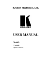
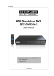
Microphone Signal Input/Output Path Block Scheme
Referring to the previous block scheme, here below the description of the “Mic Para Submenu”
pages:
Microphone Kill Fdbk – On the microphone path, the KD-1540P is implementing a powerful
“Feedback Eliminator” process based on 2 different algorithms, selectable by the user:
1. an “added Delta F” algorithm [Type-A], shifting the original band of a certain amount of
frequency, which can be set with “continuity” by the user from 0 up to 7.5Hz in 100 steps.
2. a pitch shifter algorithm [Type-B], translating the original signal band “Down” of a desired
percentage which can be set with “continuity” by the user from 0 up to 1,13% in 100
steps.
This following page allows to set the so called “SPEED” of the Frequency shift.
The choice to use as name of the parameter “Speed” is due to the intuitive understanding that can
be achieved just looking at the oscilloscope the original signal and the shifted one: if using a
sinusoid, just going from 0 up to the maximum “speed”, the frequency shifted sinusoid will appear
moving faster and faster compared to the “static” original one, used as reference for the synch.
Once entered the page, the LCD screen will display the following
Microphone
Kill Fdbk
Speed = 60%
16
Pressing once more the “ENTER” button, it is possible to edit the page's parameters and the
above window will be appear as follow
Microphone
Kill Fdbk
->
Speed = 60%
Operating on the SPEED parameter, the frequency shift applied to the band is depending from the
selected Type of Feedback Elminator (see later)
Speed [Type-A] – Amount of “constant” Frequency shift operated on the processed signal
respect the original one, ranging from 0% (No Frequency Shift) and 100% (Original band + Delta
F Shift).
So, i.e. a 1000kHz signal at Speed=100% will be shifted down to 992.5Hz, and a 2kHz signal, to
1.9925Hz.
Speed [Type-B] – Amount of Frequency shift operated on the processed signal respect the
original one, ranging from 0% (No Frequency Shift) and 100% (1,13% Band Shift).
So, i.e. a 1000kHz signal at Speed=100% will be shifted down of the 1.13%, which is 1000(1000*0.013) = 988.7Hz.
Select – within the “Select” page, the desired Feedback Elminator Type can be selected
Microphone
Kill Fdbk
->
Select = Type-A
Type-A: “added Delta F” algorithm, shifting the original band of a certain amount of frequency,
which can be set with “continuity” by the user from 0 up to 7.5Hz “Down” in 100 steps.
Type-B: “pitch shifter algorithm” [Type-B], translating the original signal band “Down” of a
desired percentage which can be set with “continuity” by the user from 0 up to 1,13% in 100
steps.
Microphone Noise Gate – this page allows to adjust the parameters of the available Noise Gate
on the microphone input path.
The LCD screen will display the following
Microphone
Noise Gate
A: 50ms R: 0.8s
-80dB
Attack Time
Threshold
Release Time
As described already in the editing section command “tree”, the parameters within the Submenu
page can be accessed pressing the “ENTER” button.
Once one parameter is selected, then at its side will appear a small “arrow”.
Once the arrow is aside the parameter, its values can be modified by the “Up/Down” buttons.
If, in example, we selected the Attack time.
17
The above window will be appear as follow
Microphone
Noise Gate
-> A: 50ms R: 0.8s
-80dB
The Attack time of the Noise Gate, then, can be set by the “Up/Down” buttons.
Once set the Attack time, the Release time and Threshold, can be selected using the “L/R” buttons
and their values again adjusted by the “Up/Down” buttons.
Attack Time [A] – the range of the selectable Noise Gate's Attack Time is going from 1ms to
480ms by steps of 1ms from 1ms to 20ms, 5ms from 20ms to 30ms, 10ms from 30ms to 100ms,
20ms from 100ms to 200ms, then a 240ms, 300ms and 400ms are available before 480ms.
The Noise Gate's Attack Time is representing the time taken by the Noise Gate to “close” the
output level after detected the lack of input signal and can be accessed from the “Microphone
Noise Gate” page, just pressing the “ENTER” button.
Release Time [R] – the range of the selectable Compressor's Release Time is going from 10ms
to 280ms by steps of 10ms.
The Noise Gate's Release Time is representing the time taken by the Noise Gate to exit from the
Output Muted condition after detected an input signal and can be accessed coming from the
previous selection of the Attack Time, just pressing the”R” button (from the Release time it is
possible to go back to the Attack time, pressing the “L” button).
Threshold – the range of the selectable Noise Gate's Threshold is going from less than -90dB (
Noise Gate OFF) up to -65dB by steps of 1 dB and can be accessed coming from the previous
selection of the Release Time, just pressing the”R” button.
Microphone HPF – this page allows to adjust the Second order HP filter available on the
microphone's input path.
Once entered the page, the LCD screen will display the following
Microphone
775 Hz Butwrth
HPF
12dB
Cutting Freq.
Filter's Slope
Filter's Type
Pressing once more the “ENTER” button, it is possible to edit the page's parameters and the
above window will be appear as follow
Microphone
->775 Hz Butwrth
HPF
12dB
Cutting Freq. – the available values of the High Pass Filter's Low Cut Frequency are ranging
from 20Hz up to 20kHz by steps of 1/12 of Oct.
The HP Low Cut Frequency can be accessed from the “Microphone HPF” page, just pressing the
“ENTER” button.
Filter Slope – the High Pass Filter's slope can range from the “No Cut-Off” (filter bypassed) up to
a 24dB/Oct (fourth order filter).
The HP Low Cut Frequency can be accessed coming from the previous selection of the Cutting
Freq., just pressing the”R” button
18
Microphone LPF – this page allows to adjust the Second order LP filter available on the
microphone's input path.
Once entered the page, the LCD screen will display the following
Microphone
775 Hz Butwrth
LPF
12dB
Cutting Freq.
Filter's Slope
Filter's Type
Pressing once more the “ENTER” button, it is possible to edit the page's parameters and the
above window will be appear as follow
Microphone
->775 Hz Butwrth
LPF
12dB
Cutting Freq. – the available values of the Low Pass Filter's Low Cut Frequency are ranging from
20Hz up to 20kHz by steps of 1/12 of Oct.
The LP High Cut Frequency can be accessed from the “Microphone LPF” page, just pressing the
“ENTER” button.
Filter Slope – the Low Pass Filter's slope can range from the “No Cut-Off” (filter bypassed) up to
a 24dB/Oct (fourth order filter).
The LP Low Cut Frequency can be accessed coming from the previous selection of the Cutting
Freq., just pressing the”R” button
Microphone PEQ: 1 (to) PEQ: 15 – here we have 15 pages with the same characteristics,
allowing to adjust 15 Peaking Filters, available on the microphone's input path.
Peaking Filters - Once entered the pages, the LCD screen will display the following, if i.e. We
want to set the Peaking Filter as Filter number 1
Microphone
10.0kHz Q=3.00
Center Freq. (Fc)
PEQ: 1
+ 0.0dB
Gain (G)
Bandwidth (Q)
Pressing once more the “ENTER” button, it is possible to edit the page's parameters and the
above window will be appear as follow
Microphone
PEQ: 1
->10.0kHz Q=3.00 + 0.0dB
Center Freq. (Fc) – this is the Peaker Filter's Center Frequency and the range of the available
values is going from 20Hz up to 20kHz by steps of 1/12 of Oct.
The Center Frequency can be accessed from the “Microphone PEQ: X” page, just pressing the
“ENTER” button.
19
Quality Factor (Q) – this is the Peaking Filter's Q and can range from the “3.0” up to “32.5” by
steps of 0.05.
The Bandwidth can be accessed coming from the previous selection of the Center Freq., just
pressing the”R” button
Gain (G) – this is the Peaking Filter's Gain and can range from the -12dB up to +12dB by steps of
0.5dB.
The Peaking filter's Gain can be accessed coming from the previous selection of the Q, just
pressing the”R” button
Microphone LoShelv – here we have the page, allowing to adjust a Low Shelving Filter, available
on the microphone's input path.
Low Shelving Filter – the following page allows to adjust the Low Shelving Filter, available on
the microphone's input path.
Once entered the page of the 2nd Order Low Shelving Filter, the LCD screen will display the
following
Microphone
1.00kHz
----
LoShelv
+ 0.0dB
Cutting Freq.
Gain
Pressing once more the “ENTER” button, it is possible to edit the page's parameters and the
above window will be appear as follow
Microphone
->1.00kHz
----
LoShelv
+ 0.0dB
Cutting Freq. – the available parameter of the Low Shelving Filter's Cutting Frequency is ranging
from 20Hz up to 20kHz by steps of 1/12 of Oct.
Gain – the Low Shelving Filter's Gain can range from -12dB up to +12dB by steps of 0.5dB.
The Low Shelving Filter's Gain can be accessed coming from the previous selection of the Cutting
Freq., just pressing the”R” button
Microphone HiShelv – here we have the page, allowing to adjust a High Shelving Filter,
available on the microphone's input path.
Low Shelving Filter – the following page allows to adjust the High Shelving Filter, available on
the microphone's input path.
Once entered the page of the 2nd Order High Shelving Filter, the LCD screen will display the
following
Microphone
1.00kHz
----
Cutting Freq.
HiShelv
+ 0.0dB
Gain
20
Pressing once more the “ENTER” button, it is possible to edit the page's parameters and the
above window will be appear as follow
Microphone
->1.00kHz
----
HiShelv
+ 0.0dB
Cutting Freq. – the available parameter of the High Shelving Filter's Cutting Frequency is ranging
from 20Hz up to 20kHz by steps of 1/12 of Oct.
Gain – the High Shelving Filter's Gain can range from -12dB up to +12dB by steps of 0.5dB.
The Low Shelving Filter's Gain can be accessed coming from the previous selection of the Cutting
Freq., just pressing the”R” button
Microphone Compressor [1/2] – this page allows to adjust the parameters of the available
RMS Compressor on the microphone input path.
The LCD screen will display the following
Microphone
Compressor
A: 50ms R: 2s 2:1 + 0
Attack Time
Threshold
Release Time
Ratio
Once one parameter is selected, then at its side will appear a small “arrow”.
Once the arrow is aside the parameter, its values can be modified by the “Up/Down” buttons.
If, in example, we selected the Attack time, the above window will appear as follow,
Microphone
Compressor
-> A: 50ms R: 2s 2:1 + 0
The Attack time of the compressor, then, can be set by the “Up/Down” buttons.
Once set the Attack time, the Release time, Ratio and Threshold, can be selected using the “L/R”
buttons and their values again adjusted by the “Up/Down” buttons.
Attack Time [A] – the range of the selectable Compressor's Attack Time is going from 1ms to
480ms by steps of 1ms from 1ms to 20ms, 5ms from 20ms to 30ms, 10ms from 30ms to 100ms,
20ms from 100ms to 200ms, then a 240ms, 300ms and 400ms are available before 480ms.
The Compressor's Attack Time can be accessed from the “Microphone Compressor” page, just
pressing the “ENTER” button.
Release Time [R] – the range of the selectable Compressor's Release Time is going from 100ms
to 2.8S by steps of 100ms.
The Compressor's Release Time can be accessed coming from the previous selection of the Attack
Time, just pressing the”R” button (from the Release time it is possible to go back to the Attack
time, pressing the “L” button).
Ratio – The range of the selectable Compressor's Ratio is going from 1:1 (no Compression), up to
20:1; the Compressor's Ratio can be accessed coming from the previous selection of the Release
Time, just pressing the”R” button (from the Ratio it is possible to go back to the Release time,
pressing the “L” button).
Threshold – the range of the selectable Compressor's Threshold is going from +0dB (Compressor
not active) up to -24dB by steps of 1 dB and can be accessed coming from the previous selection
of the Ratio, just pressing the”R” button.
21
Microphone Compressor [2/2] – this page allows to chose the “Knee” type for the RMS
compressor, editable in the following Page.
The Knee can be selected to be Hard (immediate compression after the threshold) or Soft (the
compression start smoothly before the selected Threshold).
If selected the Soft Knee, the LCD screen will display the following
Microphone
Compressor
->
Knee : Soft
Microphone CompVol – this page allows to adjust the microphone's compressor input/output
levels.
Once entered the page, the LCD screen will display the following
Microphone
In:+ 1.0dB
CompVol
Out:+ 6.0dB
Comp Input Vol
Comp Out Vol
Pressing once more the “ENTER” button, it is possible to edit the page's parameters and the
above window will be appear as follow
Microphone
->In:+ 1.0dB
CompVol
Out:+ 6.0dB
In – this is the Input Level parameter and the range of the available values is going from -6dB up
to +6dB by steps of 0.5dB.
The Compressor's Input Level can be accessed from the “Microphone CompVol” page, just
pressing the “ENTER” button.
Out – this is the Output Level parameter and the range of the available values is going from -6dB
up to +6dB by steps of 0.5dB.
The Compressor's Output Level can be accessed coming from the previous selection of the “In”
level, just pressing the”R” button.
22
●
Effect Para Submenu: Effects Editing Section
From the “Normal Operation” screen, it is possible to access the “Effect Para Submenu” using the
“EDIT” button and selecting the “Effect Para Submenu” using the L/R buttons to scroll between
the several Sub menus.
The Effect Para Submenu can also be accessed QUICKLY just pressing the “EFFECT”
button in the “EDIT” section of the KD-1540P Front Panel.
Once selected the “Effect Para Submenu”, using the “ENTER” an “L/R” buttons it is possible to
access the several pages of the Submenu, so as to enter them for the parameters' editing, which
values can be modified by the “Up/Down” buttons.
Note 1: in the all pages' options, the all possible selections can be selected as said by the
“Up/Down” buttons and the current shown value of the selected options is AUTOMATICALLY
loaded during the “Up/Down” use and stored as current value once left the page.
In the following ALL Pages, once selected the desired option and modified it, the modification is
automatically accepted as current one during the selection itself and stored in the KD-1540P
system status once left the page.
Note 2: The Effect Para Submenu's pages no need to be entered by the “ENTER” button to be
edited, containing those pages just one parameter to be edited.
Once selected the desired page for editing using the L/R buttons, then it is enough to use the
Up/Down buttons to set the parameter's value.
Effect Signal Input/Output Path Block Scheme
Referring to the previous block scheme, here below the description of the “Effect Para Submenu”
pages:
Effect Delay Pages – the KD-1540P Delay it is a pretty advanced one.
The delay is a REAL 3 TAPS one, so performing 3 independent Delays that can be pan-potted on
the Left and Right channel as desired by the user.
More, the Direct sound can be added to the delaied one with its own Pre-Delay and level.
For the 3 Taps Delay, we have 10 pages containing the Delay process editable parameters.
The 15 pages are the following:
23
Left Time – parameter setting the Delay Time of the Left Channel's Delay (Tap Delay 1), ranging
from 0ms up to 680ms by steps of 10ms
The LCD screen will display the following
Effect
Left Time:
Delay
50ms
Left Feedback – parameter setting the Feedback % of the Left Channel's Delay (Tap Delay 1),
ranging from 0% up to 100% by steps of 1%
The LCD screen will display the following
Effect
Left Feedback:
Delay
60%
Right Time – parameter setting the Delay Time of the Right Channel's Delay (Tap Delay 2),
ranging from 0ms up to 680ms by steps of 10ms
The LCD screen will display the following
Effect
Right Time:
Delay
50ms
Right Feedback – parameter setting the Feedback % of the Right Channel's Delay (Tap Delay 2),
ranging from 0% up to 100% by steps of 1%
The LCD screen will display the following
Effect
Right Feedback:
Delay
60%
Center Time – parameter setting the Delay Time of the Right Channel's Delay (Tap Delay 3),
ranging from 0ms up to 680ms by steps of 10ms
The LCD screen will display the following
Effect
Center Time:
Delay
80ms
Center Feedback – parameter setting the Feedback % of the Right Channel's Delay (Tap Delay
3), ranging from 0% up to 100% by steps of 1%
The LCD screen will display the following
Effect
Center Feedback:
24
Delay
40%
Left Pan Left – parameter setting the Percentage of Left Channel's Delay (Tap Delay 1), on the
Delay Left Output Channel, ranging from 0% up to 100% by steps of 1%
The LCD screen will display the following
Effect
Left Pan Left:
Delay
100%
Left Pan Right – parameter setting the Percentage of Left Channel's Delay (Tap Delay 1), on the
Delay Right Output Channel, ranging from 0% up to 100% by steps of 1%
The LCD screen will display the following
Effect
Left Pan Right:
Delay
0%
Right Pan Left – parameter setting the Percentage of Right Channel's Delay (Tap Delay 2), on
the Delay Left Output Channel, ranging from 0% up to 100% by steps of 1%
The LCD screen will display the following
Effect
Right Pan Left:
Delay
0%
Right Pan Right – parameter setting the Percentage of Right Channel's Delay (Tap Delay 2), on
the Delay Right Output Channel, ranging from 0% up to 100% by steps of 1%
The LCD screen will display the following
Effect
Right Pan Right:
Delay
100%
Center Pan Left – parameter setting the Percentage of Center Channel's Delay (Tap Delay 3), on
the Delay Left Output Channel, ranging from 0% up to 100% by steps of 1%
The LCD screen will display the following
Effect
Center Pan Left:
Delay
50%
Center Pan Right – parameter setting the Percentage of Center Channel's Delay (Tap Delay 3),
on the Delay Right Output Channel, ranging from 0% up to 100% by steps of 1%
The LCD screen will display the following
Effect
Center Pan Right:
25
Delay
50%
Direct Volume – parameter setting the Direct Signal Volume summed to the Left/Right Outputs
of the Stereo Delay.
The Direct Volume can be set between 0% (Direct Muted) up to 100% (Direct fully “added” to the
Stero Delay Outputs) by steps of 1%.
The LCD screen will display the following
Effect
Direct Volume:
Delay
50%
Direct PreDelay Time – parameter setting the Pre-Delay Time of the Direct signal summed to
the Left/Right Outputs of the Stereo Delay, ranging from 0ms up to 150ms by steps of 1ms.
The LCD screen will display the following
Effect
Direct PreDelay:
Delay
80ms
Out Volume – parameter setting the Stereo Delay Output Volume before the Mix with the Reverb
Effect, in order to be sent to the Microphone and Music Paths.
The Stereo Delay Volume can be set between 0% (Stereo Delay Muted) up to 100% (Stereo Delay
fully “Open”) by steps of 1%.
The LCD screen will display the following
Effect
Out Volume:
Delay
50%
Effect Reverb Pages – here we have 9 pages containing the Reverb process editable
parameters.
The 9 pages are the following:
Decay – parameter setting the Decay Time of the Reverb, ranging from 0% up to 100% by steps
of 1%
The LCD screen will display the following
Effect
Reverb
Decay:
70%
PreDelay Time – parameter setting the Pre-Delay Time of the Reverb, ranging from 0ms up to
200ms by steps of 1ms.
The LCD screen will display the following
Effect
PreDelay Time:
Reverb
80ms
Density – parameter setting the Density of the Reverb, ranging from 0% up to 100% by steps of
1%
The LCD screen will display the following
Effect
Density:
Reverb
40%
26
Loop Highpass – parameter setting the High Pass 1st order Filter of the Reverb's Main Loop,
ranging from 20Hz up to 20kHz by steps of 1/12 of Oct.
The LCD screen will display the following
Effect
Loop Highpass:
Reverb
80Hz
Loop Lowpass – parameter setting the Low Pass 1st order Filter of the Reverb's Main Loop,
ranging from 20Hz up to 20kHz by steps of 1/12 of Oct.
The LCD screen will display the following
Effect
Loop Lowpass:
Reverb
6kHz
Output HDamp – parameter setting the High Damp (Low Pass) Output Filter of the Reverb,
ranging from 20Hz up to 20kHz by steps of 1/12 of Oct.
The LCD screen will display the following
Effect
Output HDamp:
Reverb
8kHz
Output LDamp – parameter setting the Low Damp (High Pass) Output Filter of the Reverb,
ranging from 20Hz up to 20kHz by steps of 1/12 of Oct.
The LCD screen will display the following
Effect
Output LDamp:
Reverb
40Hz
Density PreDelay – parameter setting the Pre-Delay Time of the Reverb's Density, ranging from
0ms up to 200ms by steps of 1ms.
The LCD screen will display the following
Effect
Reverb
Density PreDelay: 80ms
Direct Volume – parameter setting the Direct Signal Volume summed to Reverb Output
The Direct Volume can be set between 0% (Direct Muted) up to 100% (Direct fully “added” to the
Reverb Output) by steps of 1%.
The LCD screen will display the following
Effect
Direct Volume:
Reverb
50%
Out Volume (Reverb)– parameter setting the Reverb Output Volume before the Mix with the
Delay Effect, in order to be sent to the Microphone and Music Paths.
The Reverb Volume can be set between 0% (Reverb Muted) up to 100% (Reverb fully “Open”) by
steps of 1%. The LCD screen will display the following
Effect
Out Volume:
Reverb
50%
27
DEL-PEQ / REV-PEQ [1/2/3//4/5/6] – The KD-1540P is providing 3 Peaking Filters for
“coloring” the Delay and the Reverb effects.
For any one of these effects, 3 Peaking filters are available and fully editable
Once entered the pages of the Effects Peaking Filters, the LCD screen will display the following, if
i.e. We want to set the Peaking Filter number 1 of the Delay Efx
Effect
10.0kHz
DEL-PEQ: 1
Q=3.00 + 0.0dB
Center Freq. (Fc)
Gain (G)
Bandwidth (Q)
Pressing once more the “ENTER” button, it is possible to edit the page's parameters and the
above window will be appear as follow
Effect
-> 10.0kHz
DEL-PEQ: 1
Q=3.00 + 0.0dB
Center Freq. (Fc) – this is the Peaking Filter's Center Frequency and the range of the available
values is going from 20Hz up to 20kHz by steps of 1/12 of Oct.
The Center Frequency can be accessed from the “Effect DEL-PEQ: 1” page, just pressing the
“ENTER” button.
Quality Factor (Q) – this is the Peaking Filter's Q and can range from the “3.0” up to “32.5” by
steps of 0.05.
The Q can be accessed coming from the previous selection of the Center Freq., just pressing
the”R” button
Gain (G) – this is the Peaking Filter's Gain and can range from the -12dB up to +12dB by steps of
0.5dB.
The Peaking filter's Gain can be accessed coming from the previous selection of the Q, just
pressing the”R” button
28
●
Music Para Submenu: Music Signal Processes Section
From the “Normal Operation” screen, it is possible to access the “Music Para Submenu” using the
“EDIT” button and selecting the “Music Para Submenu” using the L/R buttons to scroll between the
several Sub menus.
The Music Para Submenu can also be accessed QUICKLY just pressing the “Music”
button in the “EDIT” section of the KD-1540P Front Panel.
Once selected the “Music Para Submenu”, using the “ENTER” an “L/R” buttons it is possible to
access the several pages of the Submenu, so as to enter them for the parameters' editing, which
values can be modified by the “Up/Down” buttons.
Note: in the all pages' options, the all possible selections can be selected as said by the
“Up/Down” buttons and the current shown value of the selected options is AUTOMATICALLY
loaded during the “Up/Down” use and stored as current value once left the page.
In the following ALL Pages, once selected the desired option and modified it, the modification is
automatically accepted as current one during the selection itself and stored in the KD-1540P
system status once left the page.
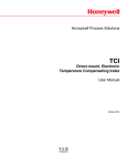
Music Signal Input/Output Path Block Scheme
Referring to the previous block scheme, here below the description of the “Music Para Submenu”
pages:
Music Noise Gate – this page allows to adjust the parameters of the available Noise Gate on the
Music input path.
The LCD screen will display the following
Music
Noise Gate
A: 50ms R: 0.8s
-80dB
Attack Time
Threshold
Release Time
As described already in the editing section command “tree”, the parameters within the Submenu
page can be accessed pressing the “ENTER” button.
Once one parameter is selected, then at its side will appear a small “arrow”.
Once the arrow is aside the parameter, its values can be modified by the “Up/Down” buttons.
If, in example, we selected the Attack time.The above window will be appear as follow
29
Music
Noise Gate
-> A: 50ms R: 0.8s
-80dB
The Attack time of the Noise Gate, then, can be set by the “Up/Down” buttons.
Once set the Attack time, the Release time and Threshold, can be selected using the “L/R” buttons
and their values again adjusted by the “Up/Down” buttons.
Attack Time [A] – the range of the selectable Noise Gate's Attack Time is going from 1ms to
480ms by steps of 1ms from 1ms to 20ms, 5ms from 20ms to 30ms, 10ms from 30ms to 100ms,
20ms from 100ms to 200ms, then a 240ms, 300ms and 400ms are available before 480ms.
The Noise Gate's Attack Time is representing the time taken by the Noise Gate to “close” the
output level after detected the lack of input signal and can be accessed from the “Music Noise
Gate” page, just pressing the “ENTER” button.
Release Time [R] – the range of the selectable Compressor's Release Time is going from 10ms
to 280ms by steps of 10ms.
The Noise Gate's Release Time is representing the time taken by the Noise Gate to exit from the
Output Muted condition after detected an input signal and can be accessed coming from the
previous selection of the Attack Time, just pressing the”R” button (from the Release time it is
possible to go back to the Attack time, pressing the “L” button).
Threshold – the range of the selectable Noise Gate's Threshold is going from less than -90dB (
Noise Gate OFF) up to -65dB by steps of 1 dB and can be accessed coming from the previous
selection of the Release Time, just pressing the”R” button.
Music KeyShift – this page allows to set the “Key” of the Music Signal.
The Music signal is processed by a Key shift Algorithm able to transpose the signal by steps of
semitones.
Once entered the page, the LCD screen will display the following
Music
KeyShift
Semitone: #
Pressing once more the “ENTER” button, it is possible to edit the page's parameters and the
above window will be appear as follow
->
Music
KeyShift
Semitone: #
Semitone – this parameter allows to decide which is the amount of transpose to apply to the
Music signal, in terms of semitones difference from the original Key.
The Value of this parameter is ranging from -12 Semitones (b12, one Octave Down) up to +12
Semitones (#12, one Octave up) by steps of 1 Semitone.
The Semitone parameter can be accessed from the “Music KeyShift” page, just pressing the
“ENTER” button.
30
Music HPF – this page allows to adjust the Second order HP filter available on the Audio's input
path.
Once entered the page, the LCD screen will display the following
Music
75 Hz
Butwrth
HPF
12dB
Cutting Freq.
Filter's Slope
Filter's Type
Pressing once more the “ENTER” button, it is possible to edit the page's parameters and the
above window will be appear as follow
Music
->75 Hz
Butwrth
HPF
12dB
Cutting Freq. – the available values of the High Pass Filter's Low Cut Frequency are ranging
from 20Hz up to 20kHz by steps of 1/12 of Oct.
The HP Low Cut Frequency can be accessed from the “Music HPF” page, just pressing the “ENTER”
button.
Filter Slope – the High Pass Filter's slope can range from the “No Cut-Off” (filter bypassed) up to
a 24dB/Oct (fourth order filter).
The HP Low Cut Frequency can be accessed coming from the previous selection of the Cutting
Freq., just pressing the”R” button
Music LPF – this page allows to adjust the Second order LP filter available on the Audio's input
path.
Once entered the page, the LCD screen will display the following
Music
7750 Hz
Butwrth
LPF
12dB
Cutting Freq.
Filter's Slope
Filter's Type
Pressing once more the “ENTER” button, it is possible to edit the page's parameters and the
above window will be appear as follow
Music
->7750 Hz
Butwrth
LPF
12dB
Cutting Freq. – the available values of the Low Pass Filter's High Cut Frequency are ranging
from 20Hz up to 20kHz by steps of 1/12 of Oct.
The LP High Cut Frequency can be accessed from the “Music LPF” page, just pressing the “ENTER”
button.
Filter Slope – the Low Pass Filter's slope can range from the “No Cut-Off” (filter bypassed) up to
a 24dB/Oct (fourth order filter).
The LP High Cut Frequency can be accessed coming from the previous selection of the Cutting
Freq., just pressing the”R” button
31
Music PEQ: 1 (to) PEQ: 15 – here we have 15 pages with the same characteristics, allowing to
adjust 15 Peaking Filters, available on the Music's input path.
Peaking Filters - Once entered the pages, the LCD screen will display the following, if i.e. We
want to set the Peaking Filter as Filter number 1
Music
10.0kHz
Q=3.00
PEQ: 1
+ 0.0dB
Center Freq. (Fc)
Gain (G)
Bandwidth (Q)
Pressing once more the “ENTER” button, it is possible to edit the page's parameters and the
above window will be appear as follow
Music
->10.0kHz
PEQ: 1
+ 0.0dB
Q=3.00
Center Freq. (Fc) – this is the Peaker Filter's Center Frequency and the range of the available
values is going from 20Hz up to 20kHz by steps of 1/12 of Oct.
The Center Frequency can be accessed from the “Music PEQ: X” page, just pressing the “ENTER”
button.
Quality Factor (Q) – this is the Peaking Filter's Q and can range from the “3.0” up to “32.5” by
steps of 0.05.
The Bandwidth can be accessed coming from the previous selection of the Center Freq., just
pressing the”R” button
Gain (G) – this is the Peaking Filter's Gain and can range from the -12dB up to +12dB by steps of
0.5dB.
The Peaking filter's Gain can be accessed coming from the previous selection of the Q, just
pressing the”R” button
Music LoShelv – here we have the page, allowing to adjust a Low Shelving Filter, available on
the Music's input path.
Low Shelving Filter – the following page allows to adjust the Low Shelving Filter, available on
the Music's input path.
Once entered the page of the 2nd Order Low Shelving Filter, the LCD screen will display the
following
Music
1.00kHz
----
LoShelv
+ 0.0dB
Cutting Freq.
Gain
Pressing once more the “ENTER” button, it is possible to edit the page's parameters and the
above window will be appear as follow
Music
->1.00kHz
----
LoShelv
+ 0.0dB
32
Cutting Freq. – the available parameter of the Low Shelving Filter's Cutting Frequency is ranging
from 20Hz up to 20kHz by steps of 1/12 of Oct.
Gain – the Low Shelving Filter's Gain can range from -12dB up to +12dB by steps of 0.5dB.
The Low Shelving Filter's Gain can be accessed coming from the previous selection of the Cutting
Freq., just pressing the”R” button
Music HiShelv – here we have the page, allowing to adjust a High Shelving Filter, available on
the Music's input path.
High Shelving Filter – the following page allows to adjust the High Shelving Filter, available on
the Music's input path.
Once entered the page of the 2nd Order High Shelving Filter, the LCD screen will display the
following
Music
1.00kHz
----
HiShelv
+ 0.0dB
Cutting Freq.
Gain
Pressing once more the “ENTER” button, it is possible to edit the page's parameters and the
above window will be appear as follow
Music
->1.00kHz
----
HiShelv
+ 0.0dB
Cutting Freq. – the available parameter of the High Shelving Filter's Cutting Frequency is ranging
from 20Hz up to 20kHz by steps of 1/12 of Oct.
Gain – the High Shelving Filter's Gain can range from -12dB up to +12dB by steps of 0.5dB.
The Low Shelving Filter's Gain can be accessed coming from the previous selection of the Cutting
Freq., just pressing the”R” button
Music Compressor [1/2] – this page allows to adjust the parameters of the available RMS
Compressor on the music output path, before to reach the Main Line Out Ch1/Ch2.
The LCD screen will display the following
Music
Compressor
A: 80ms R:2.0s 1:1 + 0
Attack Time
Threshold
Release Time
Ratio
Pressing once more the “ENTER” button, it is possible to edit the page's parameters and the
above window will be appear as follow
Music
Compressor
-> A: 80ms R:2.0s 1:1 + 0
33
Attack Time [A] – the range of the selectable Compressor's Attack Time is going from 1ms to
480ms by steps of 1ms from 1ms to 20ms, 5ms from 20ms to 30ms, 10ms from 30ms to 100ms,
20ms from 100ms to 200ms, then a 240ms, 300ms and 400ms are available before 480ms.
The Compressor's Attack Time can be accessed from the “Music Compressor” page, just pressing
the “ENTER” button.
Release Time [R] – the range of the selectable Compressor's Release Time is going from 100ms
to 2.8S by steps of 100ms.
The Compressor's Release Time can be accessed coming from the previous selection of the Attack
Time, just pressing the”R” button (from the Release time it is possible to go back to the Attack
time, pressing the “L” button).
Ratio – The range of the selectable Compressor's Ratio is going from 1:1 (no Compression), up to
20:1.
The Compressor's Ratio can be accessed coming from the previous selection of the Release Time,
just pressing the”R” button (from the Ratio it is possible to go back to the Release time, pressing
the “L” button).
Threshold – the range of the selectable Compressor's Threshold is going from +0dB (Compressor
not active) up to -30dB by steps of 1 dB and can be accessed coming from the previous selection
of the Ratio, just pressing the”R” button.
Music Compressor [2/2] – this page allows to chose the “Knee” type for the RMS compressor,
editable in the following Page.
The Knee can be selected to be Hard (immediate compression after the threshold) or Soft (the
compression start smoothly before the selected Threshold).
If selected the Soft Knee, the LCD screen will display the following
Music
Compressor
->
Knee : Soft
Music CompVol – this page allows to adjust the Music's compressor input/output levels.
Once entered the page, the LCD screen will display the following
Music
In:+ 1.0dB
CompVol
Out:+ 6.0dB
Comp Input Vol
Comp Out Vol
Pressing once more the “ENTER” button, it is possible to edit the page's parameters and the
above window will be appear as follow
Music
->In:+ 1.0dB
CompVol
Out:+ 6.0dB
In – this is the Input Level parameter and the range of the available values is going from -6dB up
to +6dB by steps of 0.5dB.
The Compressor's Input Level can be accessed from the “Music CompVol” page, just pressing the
“ENTER” button.
Out – this is the Output Level parameter and the range of the available values is going from -6dB
up to +6dB by steps of 0.5dB.
The Compressor's Output Level can be accessed coming from the previous selection of the “In”
34
level, just pressing the”R” button.
●
Main Output Para Submenu: Music Main Output Processes Section
From the “Normal Operation” screen, it is possible to access the “Main Output Para Submenu”
using the “EDIT” button and selecting the “Main Output Para Submenu” using the L/R buttons to
scroll between the several Sub menus.
The Main Output Para Submenu can also be accessed QUICKLY just pressing the “MAIN”
button in the “EDIT” section of the KD-1540P Front Panel.
Once selected the “ Main Output Para Submenu”, using the “ENTER” an “L/R” buttons it is possible
to access the several pages of the Submenu, so as to enter them for the parameters' editing,
which values can be modified by the “Up/Down” buttons.
Note: in the all pages' options, the all possible selections can be selected as said by the
“Up/Down” buttons and the current shown value of the selected options is AUTOMATICALLY
loaded during the “Up/Down” use and stored as current value once left the page.
In the following ALL Pages, once selected the desired option and modified it, the modification is
automatically accepted as current one during the selection itself and stored in the KD-1540P
system status once left the page.
Main Output Signal Input/Output Path Block Scheme
Referring to the previous block scheme, here below the description of the “ Main Output Para
Submenu” pages:
Main Output SignalFrom – this page allows to set the Level of the Audio Left/Right Processed
Signal, of the Microphone Processed Direct Signal (Equalized but without added Effects) and the
one of the Microphone Effected Signal (Effects Section Output) to be added to the Music Main
Output (see previous block scheme).
Once entered the page, the LCD screen will display the following
Main Output
SignalFrom
A: 0% M = 50% Efx = 20%
Pressing once more the “ENTER” button, it is possible to edit the page's parameters and the
above window will be appear as follow
Main Output
SignalFrom
-> A: 0% M = 50% Efx = 20%
35
A – Equalized Signal from the Left/Right (respectively) Audio Channels' path Level, to be added
to the Main Music Left/Right Outputs, ranging from 0% (Equalized Left/Right Audio Inputs Muted)
and 100% (Max Equalized Left/Right Audio Inputs Level).
The Volume parameter can be accessed from the “Music SignalFrom” page, just pressing the
“ENTER” button.
M – Equalized Direct Signal from Microphone's path Level, to be added to the Main Music
Outputs, ranging from 0% (Direct Equalized Microphone Input Muted) and 100% (Max Direct
Equalized Microphone Input Level).
The Volume parameter can be accessed from the “Music SignalFrom” page, just pressing the
“ENTER” button.
Efx – Microphone's Equalized AND Effected Signal Level, to be added to the Main Music Outputs,
ranging from 0% (Equalized AND Effected Microphone Input Muted) and 100% (Max Equalized
AND Effected Microphone Input Level).
The Volume parameter can be accessed from the “Music SignalFrom” page, just pressing the
“ENTER” button.
Main Output PEQ: 1 (to) PEQ: 3 – here we have 3 pages with the same characteristics, allowing
to adjust 3 Peaking Filters, available on the Main Music Outputs path.
Peaking Filters - Once entered the pages, the LCD screen will display the following, if i.e. We
want to set the Peaking Filter as Filter number 1
Main Output
10.0kHz Q=3.00
PEQ: 1
+ 0.0dB
Center Freq. (Fc)
Gain (G)
Bandwidth (Q)
Pressing once more the “ENTER” button, it is possible to edit the page's parameters and the
above window will be appear as follow
Main Output
->10.0kHz Q=3.00
PEQ: 1
+ 0.0dB
Center Freq. (Fc) – this is the Peaker Filter's Center Frequency and the range of the available
values is going from 20Hz up to 20kHz by steps of 1/12 of Oct.
The Center Frequency can be accessed from the “Microphone PEQ: X” page, just pressing the
“ENTER” button.
Quality Factor (Q) – this is the Peaking Filter's Q and can range from the “3.0” up to “32.5” by
steps of 0.05.
The Bandwidth can be accessed coming from the previous selection of the Center Freq., just
pressing the”R” button
Gain (G) – this is the Peaking Filter's Gain and can range from the -12dB up to +12dB by steps of
0.5dB.
The Peaking filter's Gain can be accessed coming from the previous selection of the Q, just
pressing the”R” butto
Main Output Delay – this page allows to set the microphone's output Delay Time, for “signal
alignment” purpose.
Once entered the page, the LCD screen will display the following
Main Output
Delay =
Delay
2.083mS
Rough Delay Time Adj. (1ms Steps)
Fine Delay Time Adj. (21us Steps)
36
Pressing once more the “ENTER” button, it is possible to edit the page's parameters and the
above window will be appear as follow
Main Output
Delay
Delay = -> 2.083mS
Rough Delay Time Adj. – this parameter allows to set the Microphone Delay Time by 1ms steps
from 0ms up to 80ms and can be accessed from the “Music Delay” page, just pressing the “Enter”
button.
Fine Delay Time Adj. – this parameter allows to set the Microphone Delay Time by 21us steps
from 0ms up to 0.979ms and can be accessed coming from the previous selection of the “Rough
Delay Time Adj.”, just pressing the”L/R” buttons either.
Main Output Limiter – this page allows to adjust the parameters of the available Peak Limiter on
the microphone outputs path, before to reach the Main Music Output.
The LCD screen will display the following
Main Output
Limiter
A: 80ms R:1.0s Ths: + 0
Attack Time
Threshold
Release Time
Pressing once more the “ENTER” button, it is possible to edit the page's parameters and the
above window will be appear as follow
Main Output
Limiter
-> A: 80ms R:1.0s Ths: + 0
Attack Time [A] – the range of the selectable Limiter's Attack Time is going from 1ms to 480ms
by steps of 1ms from 1ms to 20ms, 5ms from 20ms to 30ms, 10ms from 30ms to 100ms, 20ms
from 100ms to 200ms, then a 240ms, 300ms and 400ms are available before 480ms.
The Limiter's Attack Time can be accessed from the “Music Limiter” page, just pressing the
“ENTER” button.
Release Time [R] – the range of the selectable Limiter's Release Time is going from 100ms to
2.8S by steps of 100ms.
The Limiter's Release Time can be accessed coming from the previous selection of the Attack
Time, just pressing the”R” button (from the Release time it is possible to go back to the Attack
time, pressing the “L” button).
Threshold – the range of the selectable Limiter's Threshold is going from +0dB (Limiter not
active) up to -24dB by steps of 1 dB and can be accessed coming from the previous selection of
the Ratio, just pressing the”R” button.
37
●
Subwoofer Para Submenu:Subwoofer Output Processes Section
From the “Normal Operation” screen, it is possible to access the “Subwoofer Para Submenu” using
the “EDIT” button and selecting the “ Subwoofer Para Submenu” using the L/R buttons to scroll
between the several Sub menus.
The Subwoofer Para Submenu can also be accessed QUICKLY just pressing the “SUB”
button in the “EDIT” section of the KD-1540P Front Panel.
Once selected the “Subwoofer Para Submenu”, using the “ENTER” an “L/R” buttons it is possible
to access the several pages of the Submenu, so as to enter them for the parameters' editing,
which values can be modified by the “Up/Down” buttons.
Note: in the all pages' options, the all possible selections can be selected as said by the
“Up/Down” buttons and the current shown value of the selected options is AUTOMATICALLY
loaded during the “Up/Down” use and stored as current value once left the page.
In the following ALL Pages, once selected the desired option and modified it, the modification is
automatically accepted as current one during the selection itself and stored in the KD-1540P
system status once left the page.
Subwoofer Signal Input/Output Path Block Scheme
Subwoofer SignalFrom – this page allows to set the Level of the Audio Left/Right [(L+R)/2]
Signal, of the Microphone Processed Direct Signal (Equalized but without added Effects) and the
one of the Microphone Effected Signal (Effects Section Output) to be added to the Sub Output
(see previous block scheme).
Once entered the page, the LCD screen will display the following
Subwoofer
SignalFrom
A: 0% M = 50% Efx = 20%
Pressing once more the “ENTER” button, it is possible to edit the page's parameters and the
above window will be appear as follow
Subwoofer
SignalFrom
-> A: 0% M = 50% Efx = 20%
A – Equalized Signal from the Right Audio Channel's path Level, to be added to the Main Sub
Output, ranging from 0% (Equalized Right Audio Input Muted) and 100% (Max Equalized Right
Audio Input Level).The Volume parameter can be accessed from the “Sub Output SignalFrom”
page, just pressing the “ENTER” button.
38
M – Equalized Direct Signal from Microphone's path Level, to be added to the Main Sub Output,
ranging from 0% (Direct Equalized Microphone Input Muted) and 100% (Max Direct Equalized
Microphone Input Level).
The Volume parameter can be accessed from the “Sub Output SignalFrom” page, just pressing the
“ENTER” button.
Efx – Equalized Effected Signal from microphone, to be added to the Main Sub Output, ranging
from 0% (Equalized Effected Input Muted) and 100% (Max Equalized Effected Input Level).
The Volume parameter can be accessed from the “Subwoofer SignalFrom” page, just pressing the
“ENTER” button.
Subwoofer Harmony – this page allows to activate on the Sub path a Sub Harmonic
Synthesizer, improving the Sub Harmonics of an Audio Signal sent to the Sub Section,
synthesizing Sub Harmonics (one octave lower) of the the signal itself.
The genrated Sub Harmonics can be added with the desired percentage to the opriginal signal
sent to the Sub Output.Once entered the page, the LCD screen will display the following
Subwoofer
Percent = 50%
Harmony
F=24-36
Pressing once more the “ENTER” button, it is possible to edit the page's parameters and the
above window will be appear as follow
Subwoofer
-> Percent = 50%
Harmony
F=24-36
Percent – Synthesized Sub Harmonic Percentage on the Sub Output Signal, ranging from 0%
(Sub Harmonics Muted) and 100% (Max Sub Sub Harmonic Addition).
The Volume parameter can be accessed from the “Subwoofer Harmony” page, just pressing the
“ENTER” button.
F – the Sub Harmonic Synthesizer is working generating sub Harmonics on the base on the
Harmonic content of the original signal.
Particuarly, the amplitude distribution of the generated Sub Harmonics is following the shape of a
band pass filter set on the low part of the band.
The peak of this “band pass” filter, is centered on 2 possible frequencies, 60Hz and 90Hz.
This means that when selected the frequency range setting the Sub Harmonics Amplitude Peak on
60Hz (24-36Hz), the Harmonics added to the original sound will bring a “deep” and very low extra
body to the original sound.
When selected the frequency range setting the Sub Harmonics Amplitude Peak on 90Hz (3656Hz), the Harmonics added to the original sound will bring a “lioghter and more booming” extra
body to the original sound.
The Selection of the Frequency Range can be accessed coming from the previous selection of the
Percentage, just pressing the”R” button.
39
Subwoofer Source – this page allows to set the source signal for the Sub Section Input.
Particularly, the source can be one of the 2 Music Channels (after the Key Shifting) or the SUM of
both of them.Once entered the page, the LCD screen will display the following
Subwoofer
Source
Source = L + R
Pressing once more the “ENTER” button, it is possible to edit the page's parameters and the
above window will be appear as follow
->
Subwoofer
Source
Source = L + R
Source – Parameter defining which is the Input signal for the Sub Path.
The Input Signal can be one of the Music Channels (After the Key Shifting) L (Ch1) or R (Ch2), or
the SUM of both of them L + R (Ch1+Ch2)
The Source parameter can be accessed from the “Subwoofer Source” page, just pressing the
“ENTER” button.
Subwoofer Polarity – this page allows to set the Polarity if the Sub Output Signal.
Once entered the page, the LCD screen will display the following
Subwoofer
Polarity
Polarity = [ + ]
Pressing once more the “ENTER” button, it is possible to edit the page's parameters and the
above window will be appear as follow
->
Subwoofer
Polarity
Polarity = [ + ]
Polarity – Parameter defining which is the Polarity of the Sub Output Signal.
The Source parameter can be accessed from the “Subwoofer Polarity” page, just pressing the
“ENTER” button.
40
Subwoofer HPF – this page allows to adjust the Second order HP filter available on the sub's
input path.
Once entered the page, the LCD screen will display the following
Subwoofer
75 Hz Lnk/Ril
HPF
48dB
Cutting Freq.
Filter's Slope
Filter's Type
Pressing once more the “ENTER” button, it is possible to edit the page's parameters and the
above window will be appear as follow
Subwoofer
->75 Hz
Lnk/Ril
HPF
48dB
Cutting Freq. – the available values of the High Pass Filter's Low Cut Frequency are ranging
from 20Hz up to 20kHz by steps of 1/12 of Oct.
The HP Low Cut Frequency can be accessed from the “Subwoofer HPF” page, just pressing the
“ENTER” button.
Filter Slope – the High Pass Filter's slope can range from the “No Cut-Off” (filter bypassed) up to
a 48dB/Oct (eighth order filter).
The HP Low Cut Frequency can be accessed coming from the previous selection of the Cutting
Freq., just pressing the”R” button
Subwoofer LPF – this page allows to adjust the Second order LP filter available on the sub's
input path.
Once entered the page, the LCD screen will display the following
Subwoofer
250 Hz Butwrth
LPF
24dB
Cutting Freq.
Filter's Slope
Filter's Type
Pressing once more the “ENTER” button, it is possible to edit the page's parameters and the
above window will be appear as follow
Subwoofer
->250 Hz Butwrth
LPF
24dB
Cutting Freq. – the available values of the Low Pass Filter's Low Cut Frequency are ranging from
20Hz up to 20kHz by steps of 1/12 of Oct.
The HP Low Cut Frequency can be accessed from the “Subwoofer LPF” page, just pressing the
“ENTER” button.
41
Filter Slope – the Low Pass Filter's slope can range from the “No Cut-Off” (filter bypassed) up to
a 48dB/Oct (eight order filter).
The LP High Cut Frequency can be accessed coming from the previous selection of the Cutting
Freq., just pressing the”R” button
Subwoofer PEQ: 1 (to) PEQ: 3 – here we have 3 pages with the same characteristics, allowing
to adjust 3 Peaking Filters, available on the Subwoofer's input path.
Peaking Filters - Once entered the pages, the LCD screen will display the following, if i.e. We
want to set the Peaking Filter as Filter number 1
Subwoofer
10.0kHz Q=3.00
Center Freq. (Fc)
PEQ: 1
+ 0.0dB
Gain (G)
Bandwidth (Q)
Pressing once more the “ENTER” button, it is possible to edit the page's parameters and the
above window will be appear as follow
Subwoofer
->10.0kHz
Q=3.00
PEQ: 1
+ 0.0dB
Center Freq. (Fc) – this is the Peaker Filter's Center Frequency and the range of the available
values is going from 20Hz up to 20kHz by steps of 1/12 of Oct.
The Center Frequency can be accessed from the “Subwoofer PEQ: X” page, just pressing the
“ENTER” button.
Quality Factor (Q) – this is the Peaking Filter's Q and can range from the “3.0” up to “32.5” by
steps of 0.05.
The Bandwidth can be accessed coming from the previous selection of the Center Freq., just
pressing the”R” button
Gain (G) – this is the Peaking Filter's Gain and can range from the -12dB up to +12dB by steps of
0.5dB.
The Peaking filter's Gain can be accessed coming from the previous selection of the Q, just
pressing the”R” button
Subwoofer LoShelv – here we have the page, allowing to adjust a Low Shelving Filter, available
on the Subwoofer's input path.
Low Shelving Filter – the following page allows to adjust the Low Shelving Filter, available on
the Subwoofer's input path.
Once entered the page of the 2nd Order Low Shelving Filter, the LCD screen will display the
following
Subwoofer
1.00kHz
----
Cutting Freq.
LoShelv
+ 0.0dB
Gain
42
Pressing once more the “ENTER” button, it is possible to edit the page's parameters and the
above window will be appear as follow
Sunwoofer
->1.00kHz
----
LoShelv
+ 0.0dB
Cutting Freq. – the available parameter of the Low Shelving Filter's Cutting Frequency is ranging
from 20Hz up to 20kHz by steps of 1/12 of Oct.
Gain – the Low Shelving Filter's Gain can range from -12dB up to +12dB by steps of 0.5dB.
The Low Shelving Filter's Gain can be accessed coming from the previous selection of the Cutting
Freq., just pressing the”R” button
Subwoofer Compressor [1/2] – this page allows to adjust the parameters of the available RMS
Compressor on the Sub output path, before to reach the Main Sub Out.
The LCD screen will display the following
Subwoofer
Compressor
A: 80ms R:2.0s 1:1 + 0
Attack Time
Threshold
Release Time
Ratio
Pressing once more the “ENTER” button, it is possible to edit the page's parameters and the
above window will be appear as follow
Subwoofer
Compressor
-> A: 80ms R:2.0s 1:1 + 0
Attack Time [A] – the range of the selectable Compressor's Attack Time is going from 1ms to
480ms by steps of 1ms from 1ms to 20ms, 5ms from 20ms to 30ms, 10ms from 30ms to 100ms,
20ms from 100ms to 200ms, then a 240ms, 300ms and 400ms are available before 480ms.
The Compressor's Attack Time can be accessed from the “Subwoofer Compressor” page, just
pressing the “ENTER” button.
Release Time [R] – the range of the selectable Compressor's Release Time is going from 100ms
to 2.8S by steps of 100ms.
The Compressor's Release Time can be accessed coming from the previous selection of the Attack
Time, just pressing the”R” button (from the Release time it is possible to go back to the Attack
time, pressing the “L” button).
Ratio – The range of the selectable Compressor's Ratio is going from 1:1 (no Compression), up to
20:1.
The Compressor's Ratio can be accessed coming from the previous selection of the Release Time,
just pressing the”R” button (from the Ratio it is possible to go back to the Release time, pressing
the “L” button).
Threshold – the range of the selectable Compressor's Threshold is going from +0dB (Compressor
not active) up to -30dB by steps of 1 dB and can be accessed coming from the previous selection
of the Ratio, just pressing the”R” button.
43
Subwoofer Compressor [2/2] – this page allows to chose the “Knee” type for the RMS
compressor, editable in the following Page.
The Knee can be selected to be Hard (immediate compression after the threshold) or Soft (the
compression start smoothly before the selected Threshold).
If selected the Soft Knee, the LCD screen will display the following
Subwoofer
Compressor
->
Knee : Soft
Subwoofer CompVol – this page allows to adjust the Subwoofer's compressor input/output
levels.
Once entered the page, the LCD screen will display the following
Subwoofer
In:+ 1.0dB
CompVol
Out:+ 6.0dB
Comp Input Vol
Comp Out Vol
Pressing once more the “ENTER” button, it is possible to edit the page's parameters and the
above window will be appear as follow
Subwoofer
->In:+ 1.0dB
CompVol
Out:+ 6.0dB
In – this is the Input Level parameter and the range of the available values is going from -6dB up
to +6dB by steps of 0.5dB.
The Compressor's Input Level can be accessed from the “Subwoofer CompVol” page, just pressing
the “ENTER” button.
Out – this is the Output Level parameter and the range of the available values is going from -6dB
up to +6dB by steps of 0.5dB.
The Compressor's Output Level can be accessed coming from the previous selection of the “In”
level, just pressing the”R” button.
Sub Output PEQ: 1 (to) PEQ: 3 – here we have 3 pages with the same characteristics, allowing
to adjust 3 Peaking Filters, available on the Main Sub Output path.
Peaking Filters - Once entered the pages, the LCD screen will display the following, if i.e. We
want to set the Peaking Filter as Filter number 1
Sub Output
10.0kHz Q=3.00
Center Freq. (Fc)
PEQ: 1
+ 0.0dB
Gain (G)
Bandwidth (Q)
44
Pressing once more the “ENTER” button, it is possible to edit the page's parameters and the
above window will be appear as follow
Sub Output
PEQ: 1
->10.0kHz Q=3.00 + 0.0dB
Center Freq. (Fc) – this is the Peaker Filter's Center Frequency and the range of the available
values is going from 20Hz up to 20kHz by steps of 1/12 of Oct.
The Center Frequency can be accessed from the “Sub Output PEQ: X” page, just pressing the
“ENTER” button.
Quality Factor (Q) – this is the Peaking Filter's Q and can range from the “3.0” up to “32.5” by
steps of 0.05.
The Q can be accessed coming from the previous selection of the Center Freq., just pressing
the”R” button
Gain (G) – this is the Peaking Filter's Gain and can range from the -12dB up to +12dB by steps of
0.5dB.
The Peaking filter's Gain can be accessed coming from the previous selection of the Q, just
pressing the”R” button
Subwoofer Delay – this page allows to set the sub's output Delay Time, for “signal alignment”
purpose.
Once entered the page, the LCD screen will display the following
Subwoofer
Delay =
Delay
2.083mS
Rough Delay Time Adj. (1ms Steps)
Fine Delay Time Adj. (21us Steps)
Pressing once more the “ENTER” button, it is possible to edit the page's parameters and the
above window will be appear as follow
Subwoofer
Delay
Delay = -> 2.083mS
Rough Delay Time Adj. – this parameter allows to set the Subwoofer Delay Time by 1ms steps
from 0ms up to 80ms and can be accessed from the “Subwoofer Delay” page, just pressing the
“ENTER” button.
Fine Delay Time Adj. – this parameter allows to set the Subwoofer Delay Time by 21us steps
from 0ms up to 0.979ms and can be accessed coming from the previous selection of the “Rough
Delay Time Adj.”, just pressing the”R” button.
45
Subwoofer Limiter – this page allows to adjust the parameters of the available Peak Limiter on
the Audio outputs path, before to reach the Main Audio Output.
The LCD screen will display the following
Subwoofer
Limiter
A: 80ms R:1.0s Ths: + 0
Attack Time
Threshold
Release Time
Pressing once more the “ENTER” button, it is possible to edit the page's parameters and the
above window will be appear as follow
Subwoofer
Limiter
-> A: 80ms R:1.0s Ths: + 0
Attack Time [A] – the range of the selectable Limiter's Attack Time is going from 1ms to 480ms
by steps of 1ms from 1ms to 20ms, 5ms from 20ms to 30ms, 10ms from 30ms to 100ms, 20ms
from 100ms to 200ms, then a 240ms, 300ms and 400ms are available before 480ms.
The Limiter's Attack Time can be accessed from the “Subwoofer Limiter” page, just pressing the
“ENTER” button.
Release Time [R] – the range of the selectable Limiter's Release Time is going from 100ms to
2.8S by steps of 100ms.
The Limiter's Release Time can be accessed coming from the previous selection of the Attack
Time, just pressing the”R” button (from the Release time it is possible to go back to the Attack
time, pressing the “L” button).
Threshold – the range of the selectable Limiter's Threshold is going from +0dB (Limiter not
active) up to -24dB by steps of 1 dB and can be accessed coming from the previous selection of
the Ratio, just pressing the”R” button.
46
●
Center Para Submenu: Center (Microphone) Output Processes Section
From the “Normal Operation” screen, it is possible to access the “Center Para Submenu” using the
“EDIT” button and selecting the “ Center Para Submenu” using the L/R buttons to scroll between
the several Sub menus.
The Center Para Submenu can also be accessed QUICKLY just pressing the “CENTER”
button in the “EDIT” section of the KD-1540P Front Panel.
Once selected the “Center Para Submenu”, using the “ENTER” an “L/R” buttons it is possible to
access the several pages of the Submenu, so as to enter them for the parameters' editing, which
values can be modified by the “Up/Down” buttons.
Note: in the all pages' options, the all possible selections can be selected as said by the
“Up/Down” buttons and the current shown value of the selected options is AUTOMATICALLY
loaded during the “Up/Down” use and stored as current value once left the page.
In the following ALL Pages, once selected the desired option and modified it, the modification is
automatically accepted as current one during the selection itself and stored in the KD-1540P
system status once left the page.
Center Signal Input/Output Path Block Scheme
Referring to the previous block scheme, here below the description of the “Center Para Submenu”
pages:
Mic Center SignalFrom – this page allows to set the Level of the Audio Left Processed Signal, of
the Microphone Processed Direct Signal (Equalized but without added Effects) and the one of the
Microphone Effected Signal (Effects Section Output) to be added to the Mic Center Output (see
previous block scheme).
Once entered the page, the LCD screen will display the following
Mic Center
SignalFrom
A: 0% M = 50% Efx = 20%
Pressing once more the “ENTER” button, it is possible to edit the page's parameters and the
above window will be appear as follow
Mic Center
SignalFrom
-> A: 0% M = 50% Efx = 20%
47
A – Equalized Signal from the Left/Right Audio Channel's path Level, to be added to the Main Mic
Center Output, ranging from 0% (Equalized Left Audio Input Muted) and 100% (Max Equalized
Left Audio Input Level).
The Volume parameter can be accessed from the “Mic Center SignalFrom” page, just pressing the
“ENTER” button.
M – Equalized Direct Signal from Microphone's path Level, to be added to the Main Mic Center
Output, ranging from 0% (Direct Equalized Microphone Input Muted) and 100% (Max Direct
Equalized Microphone Input Level).
The Volume parameter can be accessed from the “Mic Center SignalFrom” page, just pressing the
“ENTER” button.
Efx – Microphone's Equalized AND Effected Signal Level, to be added to the Main Mic Center
Output, ranging from 0% (Equalized AND Effected Microphone Input Muted) and 100% (Max
Equalized AND Effected Microphone Input Level).
The Volume parameter can be accessed from the “Mic Center SignalFrom” page, just pressing the
“ENTER” button.
Mic Center CenterVol – this page allows to set the Output Volume of the Mic Center Output (see
previous block scheme).
Once entered the page, the LCD screen will display the following
Mic Center
CenterVol
Volume = 50%
Pressing once more the “ENTER” button, it is possible to edit the page's parameters and the
above window will be appear as follow
Mic Center
CenterVol
->
Volume = 50%
Volume – Output Level of the Main Mic Center Output, ranging from 0% (Output Muted) and
100% (Max Output Level).
The Volume parameter can be accessed from the “Mic Center CompVol” page, just pressing the
“ENTER” button.
Mic Center PEQ: 1 (to) PEQ: 3 – here we have 3 pages with the same characteristics, allowing
to adjust 3 Peaking Filters, available on the Main Mic Center Output path.
Peaking Filters - Once entered the pages, the LCD screen will display the following, if i.e. We
want to set the Peaking Filter as Filter number 1
Mic Center
10.0kHz Q=3.00
Center Freq. (Fc)
PEQ: 1
+ 0.0dB
Gain (G)
Bandwidth (Q)
48
Pressing once more the “ENTER” button, it is possible to edit the page's parameters and the
above window will be appear as follow
Mic Center
PEQ: 1
->10.0kHz Q=3.00 + 0.0dB
Center Freq. (Fc) – this is the Peaker Filter's Center Frequency and the range of the available
values is going from 20Hz up to 20kHz by steps of 1/12 of Oct.
The Center Frequency can be accessed from the “Microphone PEQ: X” page, just pressing the
“ENTER” button.
Quality Factor (Q) – this is the Peaking Filter's Q and can range from the “3.0” up to “32.5” by
steps of 0.05.
The Q can be accessed coming from the previous selection of the Center Freq., just pressing
the”R” button
Gain (G) – this is the Peaking Filter's Gain and can range from the -12dB up to +12dB by steps of
0.5dB.
The Peaking filter's Gain can be accessed coming from the previous selection of the Q, just
pressing the”R” button
Mic Center Delay – this page allows to set the microphone's output Delay Time, for “signal
alignment” purpose.
Once entered the page, the LCD screen will display the following
Mic Center
Delay =
Delay
2.083mS
Rough Delay Time Adj. (1ms Steps)
Fine Delay Time Adj. (21us Steps)
Pressing once more the “ENTER” button, it is possible to edit the page's parameters and the
above window will be appear as follow
Mic Center
Delay
Delay = -> 2.083mS
Rough Delay Time Adj. – this parameter allows to set the Microphone Delay Time by 1ms steps
from 0ms up to 80ms and can be accessed from the “Mic Center Delay” page, just pressing the
“Enter” button.
Fine Delay Time Adj. – this parameter allows to set the Microphone Delay Time by 21us steps
from 0ms up to 0.979ms and can be accessed coming from the previous selection of the “Rough
Delay Time Adj.”, just pressing the”L/R” buttons either.
49
Mic Center Limiter – this page allows to adjust the parameters of the available Peak Limiter on
the microphone output path, before to reach the Main Mic Center Output.
The LCD screen will display the following
Mic Center
Limiter
A: 80ms R:1.0s Ths: + 0
Attack Time
Threshold
Release Time
Pressing once more the “ENTER” button, it is possible to edit the page's parameters and the
above window will be appear as follow
Mic Center
Limiter
-> A: 80ms R:1.0s Ths: + 0
Attack Time [A] – the range of the selectable Limiter's Attack Time is going from 1ms to 480ms
by steps of 1ms from 1ms to 20ms, 5ms from 20ms to 30ms, 10ms from 30ms to 100ms, 20ms
from 100ms to 200ms, then a 240ms, 300ms and 400ms are available before 480ms.
The Limiter's Attack Time can be accessed from the “Mic Center Limiter” page, just pressing the
“ENTER” button.
Release Time [R] – the range of the selectable Limiter's Release Time is going from 100ms to
2.8S by steps of 100ms.
The Limiter's Release Time can be accessed coming from the previous selection of the Attack
Time, just pressing the”R” button (from the Release time it is possible to go back to the Attack
time, pressing the “L” button).
Threshold – the range of the selectable Limiter's Threshold is going from +0dB (Limiter not
active) up to -24dB by steps of 1 dB and can be accessed coming from the previous selection of
the Ratio, just pressing the”R” button.
50
●
System Submenu: Start Up Default Volumes Level Section
From the “Normal Operation” screen, it is possible to access the “System Submenu” using the
“EDIT” button and selecting the “System Submenu” using the L/R buttons to scroll between the
several Sub menus.
Once selected the “System Submenu”, using the “ENTER” an “L/R” buttons it is possible to access
the several pages of the Submenu, so as to enter them for the parameters' editing, which values
can be modified by the “Up/Down” buttons.
Note 1: in the all pages' options, the all possible selections can be selected as said by the
“Up/Down” buttons and the current shown value of the selected options is AUTOMATICALLY
loaded during the “Up/Down” use and stored as current value once left the page.
In the following ALL Pages, once selected the desired option and modified it, the modification is
automatically accepted as current one during the selection itself and stored in the KD-1540P
system status once left the page.
Note 2: The System Submenu's pages no need to be entered by the “ENTER” button to be edited,
containing those pages just one parameter to be edited.
Once selected the desired page for editing using the L/R buttons, then it is enough to use the
Up/Down buttons to set the parameter's value.
Here below the description of the “System Submenu” pages:
Music StartUp Volume – parameter setting the Music Output Volume at the Unit Start Up, which
will be automatically Set by the unit once powered ON.
The Music StartUp Vol can be set between 0% (Music StartUp Vol Muted) up to 100% (Music
StartUp Vol fully “Open”) by steps of 1%.
The LCD screen will display the following
System Submenu
Music StartUp Vol: 50%
Sub StartUp Volume – parameter setting the Sub Output Volume at the Unit Start Up, which will
be automatically Set by the unit once powered ON.
The Sub StartUp Vol can be set between 0% (Sub StartUp Vol Muted) up to 100% (Sub StartUp
Vol fully “Open”) by steps of 1%.
The LCD screen will display the following
System Submenu
Sub StartUp Vol: 70%
Mic StartUp Volume – parameter setting the Mic Output Volume at the Unit Start Up, which will
be automatically Set by the unit once powered ON.
The Mic StartUp Vol can be set between 0% (Mic StartUp Vol Muted) up to 100% (Mic StartUp Vol
fully “Open”) by steps of 1%.
The LCD screen will display the following
System Submenu
Mic StartUp Vol: 90%
51
Effect StartUp Volume – parameter setting the Effect Output Volume at the Unit Start Up, which
will be automatically Set by the unit once powered ON.
The Effect StartUp Vol can be set between 0% (Effect StartUp Vol Muted) up to 100% (Effect
StartUp Vol fully “Open”) by steps of 1%.
The LCD screen will display the following
System Submenu
Effect StartUp Vol: 80%
Center StartUp Volume – parameter setting the Center Output Volume at the Unit Start Up,
which will be automatically Set by the unit once powered ON.
The Center StartUp Vol can be set between 0% (Center StartUp Vol Muted) up to 100% (Center
StartUp Vol fully “Open”) by steps of 1%.
The LCD screen will display the following
System Submenu
Center Maximum Vol: 70%
Music Maximum Volume – parameter setting the Maximum Music Output Volume, which will be
automatically forbidden to exceed by the unit once attempted by the user editing action.
The Music Maximum Vol can be set between 0% (Music Maximum Vol Muted) up to 100% (Music
Maximum Vol fully “Open”) by steps of 1%.
The LCD screen will display the following
System Submenu
Music Maximum Vol: 50%
Sub Maximum Volume – parameter setting the Maximum Sub Output Volume, which will be
automatically forbidden to exceed by the unit once attempted by the user editing action.
The Sub Maximum Vol can be set between 0% (Sub Maximum Vol Muted) up to 100% (Sub
Maximum Vol fully “Open”) by steps of 1%.
The LCD screen will display the following
System Submenu
Sub Maximum Vol: 70%
Mic Maximum Volume – parameter setting the Maximum Mic Output Volume, which will be
automatically forbidden to exceed by the unit once attempted by the user editing action.
The Mic Maximum Vol can be set between 0% (Mic Maximum Vol Muted) up to 100% (Mic
Maximum Vol fully “Open”) by steps of 1%.
The LCD screen will display the following
System Submenu
Mic Maximum Vol: 90%
52
Effect Maximum Volume – parameter setting the Maximum Effects Output Volume, which will
be automatically forbidden to exceed by the unit once attempted by the user editing action.
The Effect Maximum Vol can be set between 0% (Effect Maximum Vol Muted) up to 100% (Effect
Maximum Vol fully “Open”) by steps of 1%.
The LCD screen will display the following
System Submenu
Effect Maximum Vol: 80%
Center Maximum Volume – parameter setting the Maximum Center Output Volume, which will
be automatically forbidden to exceed by the unit once attempted by the user editing action.
The Center Maximum Vol can be set between 0% (Center Maximum Vol Muted) up to 100%
(Center Maximum Vol fully “Open”) by steps of 1%.
The LCD screen will display the following
System Submenu
Center Maximum Vol: 70%
Music Routing Inp – the KD-1540P is a Unit equipped by a pair of Stereo Line inputs called
Left/Right Input A and Left/Right Input B.
Furthermore, the KD-1540P is also equipped with a Digital S/PDIF Input, so called DIG.
The “Music Routing Input” parameter allows to select the Music Input to be used as Source for the
Music Path.
The Music Routing Input parameter can be InA, there where the selected Left/Right inputs are
coming from the Physical Input A, or InB, there where the selected Left/Right inputs are coming
from the Physical Input A or, finally, DIG, there where the selected Left/Right inputs are coming
from the Physical S/PDIF Input.
The LCD screen will display the following
System Submenu
Music Routing Inp: InA
53
●
Security Submenu: Password Management
The KD-1540P, has the possibility to set a Password allowing the user to “lock” the unit in order to
not let it use the editing functions once set the all presets....unless knowing the Password.
The Password is a 6 character word, which can be chosen by the user and stored in the unit just
accessing the Security Submenu.
From the “Normal Operation” screen, it is possible to access the “Security Submenu” using the
“EDIT” button and selecting the “Security Submenu” using the L/R buttons to scroll between the
several Sub menus.
Once selected the “Security Submenu”
Security Submenu
Unit Lock
From the “Unit Lock” Menu, pressing once more the “ENTER” button, it is possible finally to access
the “Enter Password” Page.
Enter Password
[_
]
Once entered the “Enter Password” page, a field for writing the 6 characters password will appear
and inside it a “blinking down score” will indicate the place where the next character will be
placed.
The character can be selected using the Up/Down buttons.
Once placed the character, to move to the next one it is necessary to use the L/R buttons.
The “blinking down score” will move on the place that will “guest” the next character.
In the above way the password can be set.
In example, if the Password is ALL ZEROS, then the screen, after written it, will be the following
Enter Password
[000000]
Once selected the Password, need to press again the “ENTER” button.
The KD-1540P0 will ask again to confirm the previously set password
Confirm Password
[_
]
If the re-entered password is the same as the one just set previously, then the Unit will display
the following screen
Locking Unit
[000000]
Once the Unit is locked, a “lock” symbol will appear on the “Normal Operation” Screen, indicating
that the unit is locked.
To Un-lock the unit, it is enough to follow the same procedures used for locking it...
Once Un-locked the unit, from the “Normal Operation” screen the “lock” symbol will be removed.
54
●
Other Front Panel Controls
Again referring to the below Front Panel's picture, other controls for the quick access to the KD1540P functions are available.
Microphones Input Level Adj
Trimmers
Inputs Clip Leds
Infrared Sensor
Mic Jacks
Editing Section Controls
Effects, Microphones and Music fast Output Level Controls
Quick Edit Process Select
Effects, Microphones and Music fast Output Level Controls – these are 3 relative encoders
which allow to access directly the Output Level of the related Effect, Mic and Music signals.
From the default “Normal Operation” screen, it is enough to use the related encoder so to adjust
the Mic/Center, Music/Sub and Effect Sections' Output Signals Level
Particularly, starting from the “Normal Operation” screen as the following
-> 70%
-> 60%
C: 50%
S: 60%
Fx: 30%
InA
Accessing the Relative encoders, the Level control can operated as follow
Effect Encoder – Rotating it clockwise or counter-clockwise, it is possible to quickly increase or
decrease, respectively, the Effect Output Signal Level
Once rotated the encoder, the “Normal Operation' screen will display the percentage of Signal
Level currently set for the Effect Output Signal
-> 70%
-> 60%
C: 50%
S: 60%
Fx: 30%
InA
Once selected the desired Level, this will be automatically stored by the unit.
The Effect Encoder has also the “Push Button” function: maintained the Effect Encoder pushed for
at least 2 seconds, it is possible to activate/deactivate the Effects.
When the effects are not active, the green “Bypass” led on top of the Effect Encoder will turn ON.
Mic Encoder – Rotating it clockwise or counter-clockwise, it is possible to quickly increase or
decrease, respectively, the Mic Output Signal Level
Once rotated the encoder, the “Normal Operation' screen will display the percentage of Signal
Level currently set for the Mic Output Signal
-> 70%
-> 60%
C: 50%
S: 60%
55
Fx: 30%
InA
Once selected the desired Level, this will be automatically stored by the unit.
The Mic Encoder has also the “Push Button” function:
1. Quickly pushing the Mic Encoder button, it is possible to select the Center output as
destination of the Level Adjustment Control.
In this case, the arrow located aside the 'Microphone' Icon when the encoder is acting on
the Microphone channel, will move aside the “C” of Center channel
: 70% C-> 50%
-> 60% S: 60%
Fx: 30%
InA
Now with the Mic Encoder it is possible to adjust the Center channel level.
To go back to the Mic channel adjustment, it is enough to push quickly the Mic Encoder
again
2. maintained the Mic Encoder pushed for at least 2 seconds, it is possible to Mute/Unmute
the Microphone input, so Muting the Microphone path and avoiding the signal coming from
the microphone to appear on any of the outputs.
When the Microphone path is muted, the red “Mute” led on top of the Mic Encoder will turn
“ON”
Music Encoder – Rotating it clockwise or counter-clockwise, it is possible to quickly increase or
decrease, respectively, the Music Output Signal Level
Once rotated the encoder, the “Normal Operation' screen will display the percentage of Signal
Level currently set for the Music Output Signal
-> 70%
-> 60%
C: 50%
S: 60%
Fx: 30%
InA
Once selected the desired Level, this will be automatically stored by the unit.
The Music Encoder has also the “Push Button” function:
3. Quickly pushing the Music Encoder button, it is possible to select the Sub output as
destination of the Level Adjustment Control.
In this case, the arrow located aside the 'Notes' Icon when the encoder is acting on the
Music channel, will move aside the “S” of Sub channel
-> 70% C: 50%
: 60% S-> 60%
Fx: 30%
InA
Now with the Music Encoder it is possible to adjust the Sub channel level.
To go back to the Music channel adjustment, it is enough to push quickly the Music
Encoder again
4. maintained the Music Encoder pushed for at least 2 seconds, it is possible to Mute/Unmute
the Music input, so Muting the Music path and avoiding the signal coming from the Audio
Inputs to appear on any of the outputs.
When the Music path is muted, the red “Mute” led on top of the Music Encoder will turn
“ON”
56
EDIT Selection – these are 3 buttons which allow to quickly access the Editable processes of the
several Submenus related to the main Sections of the KD-1540P:
EFFECT: this button, when pressed, allow the quick access to the editable parameters of the
Effects Section.
Once pressed the EFFECT button of the EDIT Section, the first page of the “Effect Para Submenu”
will be displaied on the LCD:
Effect
Left Time:
Delay
50ms
MIC: this button, when pressed, allow the quick access to the editable parameters of the
Microphone Input Path Section
Once pressed the MIC button of the EDIT Section, the first page of the “Mic Para Submenu” will be
displaied on the LCD:
Microphone
Kill Fdbk
Speed = 60%
MUSIC: this button, when pressed, allow the quick access to the editable parameters of the
Audio/Music Input Path Section
Once pressed the MUSIC button of the EDIT Section, the first page of the “Music Para Submenu”
will be displaied on the LCD:
Music
Noise Gate
A: 50ms R: 0.8s
-80dB
MAIN: this button, when pressed, allow the quick access to the editable parameters of the
Audio/Music Output Path Section
Once pressed the MAIN button of the EDIT Section, the first page of the “Main Out Para Submenu”
will be displaied on the LCD:
Main Output
SignalFrom
A: 0% M = 50% Efx = 20%
SUB: this button, when pressed, allow the quick access to the editable parameters of the
Audio/Sub Section
Once pressed the SUB button of the EDIT Section, the first page of the “Subwoofer Para
Submenu” will be displaied on the LCD:
Subwoofer
SignalFrom
A: 0% M = 50% Efx = 20%
57
CENTER: this button, when pressed, allow the quick access to the editable parameters of the
Microphone Output Path Section
Once pressed the CENTER button of the EDIT Section, the first page of the “Center Para
Submenu” will be displaied on the LCD:
Mic Center
SignalFrom
A: 0% M = 50% Efx = 20%
Mic Jacks – these are 3 “Jack Style” un-balanced mono inputs for 3 microphones quick plug-in.
Microphones Input Level Adj Trimmers – these are 3 “trimmers”, accessible through (plastic)
screwdriver, allowing to adjust the microphones input signal levels.
Infrared Sensor – Infrared Sensor used for collecting the command coming from the Infrared
external remote controller.
Input Clip Leds – Leds indicating, when flashing, the occurring clip on the related input.
Particularly:
1. MI Clip Led: is the led indicating an occurring CLIP on the Microphone Input
In a such case, need to reduce the microphone's input level through, in example, the
Microphones Input Level Adj Trimmers.
2. AI Clip Led: is the led indicating an occurring CLIP on the Audio Inputs
In a such case, need to reduce the Audio's input level through, in example, the Input
Range switches on the KD-1540P back panel.
Process Overflows – Leds indicating, when flashing, the occurring overflow on the related input.
Particularly:
1. MOV Clip: is the led indicating an occurring OVERFLOW on the Microphone path's
2.
3.
processes (Filtering, Effects, etc.); in a such case, need to reduce the Input Level at the
microphone path, in example reducing the digital input gain.
AOV Clip:is the led indicating an occurring OVERFLOW on the Audio path's processes
(Filtering, etc.); in a such case, need to reduce the Input Level at the Audio path, in
example reducing the digital input gain.
SOV Clip:is the led indicating an occurring OVERFLOW on the Sub path's processes
(Filtering, etc.); in a such case, need to reduce the Input Level at the Audio/Sub path, in
example reducing the digital input gain.
58
●
Infrared Remote Control
The KD-1540P Digital Speaker Processor can be controlled remotely by an Infrared Remote
Control, allowing to control some basic function of the unit.
Referring to the remote controller here below
Music Key Shift Controls
Effect, Microphone and
Music Volume Controls
{
b
n
#
+
+
+
EFFECT
VOL
MIC
VOL
MUSIC
VOL
-
-
-
-
SUB
WOOFER
+
CENTER
+
Subwoofer Volume Control
Center Volume Control
-
Preset Select Controls
1
EFFECT
2
3
4
Music Key Shift Controls: the 3 buttons of this section are replicating the functions of the three
buttons of the front panel, used for the Music Key Transpose, described in the “Quick Music Key
Selection” paragraph:
“b” Button – Pushing it, it is possible transpose DOWN of one semitone, ANY TIME the button
is pressed, the current Key of the Music Signal.
“#” Button – Pushing it, it is possible to quickly transpose UP of one semitone, ANY TIME the
button is pressed, the current Key of the Music Signal.
“ “ Button – Pushing it, it is possible to quickly go back to the ORIGINAL Key of the Music
Signal.
Once pushed the above buttons, the “Normal Operation” screen will display the current transpose
down or up (if any) of the Music signal, respect the Original Key.
59
Effect, Microphone and Music Volume Controls: the 6 buttons of this section are replicating
the functions of the three relative encoders of the front panel, used for the Effect/Mic/Music
Volume Control, described in the “Effects, Microphones and Music fast Output Level
Controls” paragraph:
Effect Vol +/- Buttons – using the + and – “Effect Vol” buttons, it is possible to increase or
decrease, respectively, the Effect Output Signal Level
Mic Vol +/- Buttons – using the + and - “Mic Vol” buttons, it is possible to increase or decrease,
respectively, the Mic Output Signal Level
Music Vol +/- Buttons – using the + and - “Music Vol” buttons, it is possible to increase or
decrease, respectively, the Music Output Signal Level
Once used the above buttons, the new Volume settings will be displayed on the Front Panel's LCD.
Subwoofer Volume Control: using the + and – “Subwoofer” button, it is possible to increase or
decrease, respectively, the Subwoofer Output Signal Level
Center Volume Control: using the + and – “Center” button, it is possible to increase or
decrease, respectively, the Subwoofer Output Signal Level
Preset Select Control: the 4 buttons of this section are replicating the functions of the “LOAD”
buttons of the front panel, allowing the selection of one of the first 4 presets of the 20 available
on the KD-1540P.
NOTE: the KD-1540P Unit is compatible with the BMB Remote control.
60
● Back Panel Connectors
Referring to the below Back Panel's Drawing
Mic XLR Inputs – female XLR inputs for the microphones.
These inputs are the “equivalent” balanced of the front panel un-balanced Jack inputs.
Th microphone input level is also for the back panel's inputs controlled by the front panel's
trimmers.
Line Inputs A1/A2 – RCA inputs for the 2x external Line Sources.
The A1 and A2 inputs can be selected by Sw.
Digital Inputs – RCA input for an external S/PDIF Source.
The S/PDIF input can be selected by Sw.
Line Output – RCA “REC” output for an external Recording Device.
XLR Outputs – male XLR outputs providing the result of the KD-1540P Karaoke Unit processes:
LEFT: Main Music Output Left.
Right: Main Music Output Right
Sub: Main Sub Output
Mic/Center: Main Microphone Output or Central Output
USB Connector – socket for the USB cable connection, allowing the connection between the
Karaoke Processor KD-1540P and an external USB remote control as a PC.
The KD-1540P can be fully remotely controllable by a Pc Sw running under Windows XP.
Wired Remote Control Connector – socket for the “wired Remote Control connector” which can
be used as wired remote control solution in alternative to the infrared control operated through
the front panel's sensor, for the Commands Remote Transfer.
Note: the KD-1540P's back panel has four 3 positions slide switches allowing to modify the Line
A1/A2 inputs Sensitivity so as the Left/Right Music Output and Mic/Center and Sub Outputs
sensitivities, and in details:
Line A1/A2 Input Slide Switches:
Position
Position
Position
Left/Right Music Output Slide Switches:
Position
Position
Position
Mic/Center and Sub Output Slide Switches: Position
Position
Position
61
“L”
“M”
“H”
“L”
“M”
“H”
“L”
“M”
“H”
- 9dB
+0dB
+9dB
- 9dB
+0dB
+6dB
- 9dB
+0dB
+6dB
●
KD-1540P Technical Specifications
The KD-1540P Digital Karaoke Processor is based on a powerful analog and digital DSP platforms
having the following specifications
Analog Input Signal:
Line A
Line B
Mic 1
Mic 2
Left/Right, Un-Balanced, RCA
Left/Right, Un-Balanced, RCA
Mono, Balanced, XLR Female
Mono, Balanced, XLR Female
Maximum Input Level:
Line
Mic
+12dBu
-30dB
Digital Input Signal:
S/PDIF
RCA
Analog Output Signal:
-Ch4
Balanced XLR Male
AuxL/R
Left/Right,Un-bALANCED,RCA
Maximum Output Level:
-Ch4
+15dBu
Digital Processing (DSP):
DSP Engine Dream(Voice),24bit(data)x96bit(coeff.),Sw
Enhanced Precision
Sampling Frequency:
48kHz
S/N:
>106dBA
THD+N:
0.005%
Frequency Response (Bypass):
20Hz – 20kHz (+- 1 dB)
Power Supply:
Switching Power Supply
Remote Control:
USB, Infrared, Wired
KD-1540P processes and Paths Block Scheme