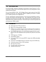
1
NuPRO-800 Series
Full Size Dual Pentium-III Industrial SBC
User's Guide
©Copyright 2000 ADLINK Technology Inc.
Manual Rev. 1.00: September 6, 2000
The information in this document is subject to change without prior notice in
order to improve reliability, design and function and does not represent a
commitment on the part of the manufacturer.
In no event will the manufacturer be liable for direct, indirect, special, incidental,
or consequential damages arising out of the use or inability to use the product
or documentation, even if advised of the possibility of such damages.
This document contains proprietary information protected by copyright. All
rights are reserved. No part of this manual may be reproduced by any
mechanical, electronic, or other means in any form without prior written
permission of the manufacturer.
Trademarks
NuPRO is a registered trademark of ADLINK Technology Inc.,
Other product names mentioned herein are used for identification purposes
only and may be trademarks and/or registered trademarks of their respective
companies.
Getting service from ADLINK
♦ Customer Satisfaction is always the most important thing for ADLINK
Tech Inc. If you need any help or service, please contact us and get it.
ADLINK Technology Inc.
http://www.adlink.com.tw
Web Site
http://www.adlinktechnology.com
Sales & Service [email protected]
NuDAQ
[email protected]
NuDAM
[email protected]
Technical
NuIPC
[email protected]
Support
NuPRO
[email protected]
Software
[email protected]
TEL
+886-2-82265877
FAX
+886-2-82265717
Address
9F, No. 166, Jian Yi Road, Chungho City, Taipei, 235 Taiwan, R.O.C.
♦ Please inform or FAX us of your detailed information for a prompt,
satisfactory and constant service.
Detailed Company Information
Company/Organization
Contact Person
E-mail Address
Address
Country
TEL
Web Site
FAX
Questions
Product Model
Environment to Use
Challenge Description
Suggestions to ADLINK
¨OS:
¨Computer Brand:
¨M/B:
¨CPU :
¨Chipset :
¨BIOS :
¨Video Card:
¨Network Interface Card:
¨Other:
Table of Contents
Chapter 1 Introduction ............................................................. 1
1.1
1.2
1.3
1.4
Checklist......................................................................................................1
Introduction ................................................................................................2
Features.......................................................................................................2
Specifications.............................................................................................3
Chapter 2 Installation.............................................................. 6
2.1
CPUs and coolers Installation ...............................................................6
2.2
Memory Installation..................................................................................7
2.3
Jumpers on the NuPRO-800...................................................................7
2.3.1
JP5: FSB (front-side-bus) Frequency..........................................8
2.3.2
JP7: Clear CMOS ...............................................................................8
2.3.3
JP11: LCD Power Selection............................................................8
2.4
Connectors Pin Assignments...............................................................9
2.5
Software Installation Tips ................................................................... 13
Chapter 3 BIOS Configuration............................................... 14
Chapter 4 SCSI Drivers Installation ...................................... 15
4.1
4.2
4.3
4.4
Software and Drivers Support ............................................................ 15
Driver Installation on Windows 2000................................................ 16
Driver Installation on Windows 98..................................................... 16
Driver Installation on Windows NT.................................................... 17
Chapter 5 VGA Drivers Installation....................................... 19
5.1
5.2
5.3
Driver Installation on Windows 2000................................................ 19
Driver Installation on Windows 98..................................................... 20
Driver Installation on Windows NT.................................................... 21
Chapter 6 LAN Drivers Installation ....................................... 22
6.1
6.2
6.3
6.4
Software and Drivers Support ............................................................ 22
Driver Installation on Windows 2000................................................ 23
Driver Installation on Windows 98..................................................... 24
Driver Installation on Windows NT.................................................... 25
Chapter 7 Watchdog Programming .................................. 26
7.1
7.2
7.3
Watchdog Timer Configuration .......................................................... 26
WDT Programming ................................................................................ 26
How to Test the WDT? .......................................................................... 27
Table of Contents • i
Chapter 8 Hardware Doctor Utility........................................ 28
Appendix A: I/O Address MAP .............................................. 29
Product Warranty/Service ...................................................... 30
ii • Table of Contents
How to Use This Manual
This manual is designed to help you to use the NuPRO-800/801.
Chapter 1 Introduction gives an overview of the product features and
specifications.
Chapter 2 Installation describes how to install the SBC. The PCB layout,
jumper setting and connector pin assignments are shown.
Chapter 3 BIOS Configuration describes how to get the BIOS configuration
information
Chapter 4 SCSI Drivers Installation describes how to install the SCSI
drivers in a Windows based environment.
Chapter 5 VGA Drivers Installation describes how to install the VGA drivers
in a Windows based environment.
Chapter 6 LAN Drivers Installation describes how to install the Intel 82559
LAN drivers in a Windows based environment.
Chapter 7 Watchdog Programming describes how to the watchdog timer.
Chapter 8 Hardware Doctor Utility shows the functionality of the hardware
doctor utility.
NuPRO-800 Series Function List
Model
NuPRO-800
NuPRO-801
Processor
Pentium III
Pentium III
Processor Socket
Socket 370
Socket 370
Chipset
Intel 82443BX /
82371EB
Intel 82443BX /
82371EB
BIOS
Award PnP BIOS
Award PnP BIOS
L2 cache
CPU Integrated
CPU Integrated
Max. SDRAM
768 MB
768 MB
Memory Sockets
168-pin DIMM x 3 with 168-pin DIMM x 3 with
ECC capability
ECC capability
VGA CRT
SMI Lynx 3DM4
SM721 AGP
SMI Lynx 3DM4
SM721 AGP
Ethernet
(10/100Mbps)
Intel 82559
Intel 82559
SCSI
LSI/SYMBIOS 53C895
N.A
Multi I/O Chip
Winbond W83977EF
Winbond W83977EF
Enhanced IDE
Yes
Yes
2S/1P
Yes
Yes
USB
Yes
Yes
IrDA
Yes
Yes
H/W Monitoring
Winbond 83782
Winbond 83782
1
Introduction
This manual is designed to provide you information on the NuPRO-800 series
CPU boards. The information inside this user’s manual can be applied to both
NuPRO-800 and NuPRO-801, except that the SCSI relative information is for
NuPRO-800 only. Therefore, we will only use the NuPRO-800 model number
to present both 800 and 801 in this user’s manual.
The topics covered in this chapter are as follows:
Ø Checklist
Ø
Introduction
Ø
Features
Ø
Specifications
1.1 Checklist
Please check that your package is complete and contains the items below. If
you discover damaged or missing items, please contact your dealer.
• The NuPRO-800 Industrial Computer Main Board
• This User's Manual
• One IDE ribbon cable
• One floppy ribbon cable
• Mounting bracket with cable for 1 serial ports and 1 parallel port
• Mounting bracket with cable for 2-port USB ports
• One SCSI flex cable (for NuPRO-800 only)
• One ADLINK CD contains drivers and utilities
Introduction • 1
1.2 Introduction
The NuPRO-800 industrial computer is optimized for dual Pentium III CPU.
This board is based on the Intel 443BX chipset and is fully designed for harsh
industrial environment.
The on board AGP4X VGA, 10/100 Mbps Ethernet and optional Ultra SCSI
interface provide the most advanced interface capability and make it suitable
for CTI and high end server applications.
The key components inside are chosen on the long-term availability criterion,
such as Intel Chipset and SMI APG chip. We guarantee this product will be
available until the end of Year 2005. Even longer life is still possible which is
dependent on the marketing situation. We also accept to extend the product life
cycle based on OEM contract.
1.3 Features
l
Dual Pentium III CPU processors
l
Best CPU cooling design concept
l
PCB layout considers minimum trace length of a ll the critical bus
includes front-side-bus (FSB), memory bus, AGP bus and PCI bus.
l
Long MTBF and stability (all critical bypass capacitors are using
Sanyo’s OS CON capacitors which provide 20 years life time at 65
°C. )
l
FSB Frequency: 100 MHz
l
Intel 440BX chipset
l
On board APG2X VGA using SMI721 chipset with 4MB embedded
Video RAM
l
On board 10/100 Mbps Ethernet interface using Intel 82559 chip
l
On board optional Ultra-II SCSI interface
l
ISA High Drive 64mA
l
Programmable watchdog timer
l
Hardware Monitoring
2 • Introduction
1.4 Specifications
l
Processor: Dual Intel Pentium III FC-PGA CPU
Ø Processor Socket: Socket-370 connector
Ø Cache: 256KB Level 2 build-in Pentium III CPU (refer to the
specifications of the Intel CPU.)
l
Front Side Bus (FSB) Frequency: 100MHz
l
Chipset:
Ø Intel 82440BX AGPset: 82443BX and 82371EB(PIIX4)
Ø Optimized SDRAM supported
l
Memory Sockets:
Three 168-pin DIMM sockets, maximum 768 MB SDRAM
Memory type: PC-100 SDRAM with or without ECC capability
BIOS: Award BIOS, PnP support
Ø DMI BIOS Support: Desktop Management Interface (DMI)
allows users to download system hardware-level information
such as CPU type, CPU speed, internal/external frequencies
and memory size.
Ø Green Function: Power management via BIOS, activated
through mouse/keyboard movement, support system soft
power off (via ATX power supply)
Ø Customized power-on screen (for OEM options)
Ø Write protection, provide anti-virus capability
l
l
AGP VGA Interface:
Ø AGP-bus VGA/LCD controller SMI Lynx3DM4 SM721, with
build-in 4M VRAM (8M VRAM is available for OEM)
Ø AGP 2X, ACPI and VESA compliant
Ø 128-bit, single clock cycle 2D drawing engine
Ø High performance, power managed 3D acceleration engine
Ø Support up to 1600x1200 resolution both in VGA and TFT LCD
Ø Simultaneous display for both VGA and LCD
Ø RAMDAC Latch-up protection
Ø Power lines on VGA connector are with over-current protection
by resetable fuse.
l
SCSI Interface:
Ø LSI / SYMBIOS SYM 53C895 advanced SCSI controller
Ø Wide Ultra-2 SCSI protocol up to 80 MB/s transfer rate (max.)
Ø LVD link to extend cable length up-to 12 meters
Introduction • 3
Ø Backward compatible with Wide Ultra-2 SCSI, Wide Ultra SCSI,
Ultra SCSI, and Fast SCSI
Ø Auto Switch transmission modes for different kind of devices
connected, suppose Signal-ended (SE), Low Voltage
Differential (LVD), High Voltage Differential (HVD)
l
Ethernet Interface:
Ø Intel 82559 chipset with 32-bit PCI interface
Ø 10/100Mbps operation in a single port PCI bus master
architecture
Ø IEEE 802.3 10base-T and 100base-TX compatible
Ø IEEE802.3u auto-negotiation support for automatic speed
selection
Ø IEEE 802.3X (100base-TX Flow control support)
Ø Wake On Lan support
Ø Optional Alert-On LAN II (AOL2)
l
USB Interface:
Two USB pin-header connectors, compliant with USB Specification
Rev. 1.1, Individual port is with over-current protection by using
resetable fuse.
l Enhanced IDE:
Bus Master IDE controller, two EIDE interfaces for up to four IDE
devices, including HDD, ATAPI CD-ROM, LS120, and ZIP drives.
Support PIO Mode 3/4 or Ultra DMA/33 IDE devices,
l Super I/O:
Ø Chipset: Winbond W83977EF:
Ø Parallel Port:
• One high-speed parallel port, SPP/EPP/ECP mode
• ESD protection to 4KV and downstream device protection to
30V
Ø Serial Port:
• Two 16C550 UART compatible RS-232 COM ports
• ESD protection to 2KV
Ø FDD Interface: Support two floppy drives (360KB, 720KB,
1.2MB, 1.44MB, 2.88MB)
Ø Keyboard and Mouse Connectors: PS/2 type mini-DIN
connectors, supports a 5-pin internal keyboard connector. All
connectors are with over-current protection.
Ø IrDA: Supports 5 -pin IrDA interface with over-current protection
l
PCI Compliance: Fully compliant to PCI rev. 2.1 standards and
PICMG 1.0 PCI-ISA standard
4 • Introduction
l
Hardware Monitoring: Winbond W83782D, Monitoring CPU
temperature, 2 CPU fans speed, case open and DC Voltages
l
Watchdog Timer:
Ø Programmable I/O port 2Eh and 2Fh to configure watchdog
timer, programmable timer 1~15300 seconds.
Ø Bundled easy-programming source code and library for DOS,
Windows 95, 98, NT
l
ISA High Driving Capability:
ISA bus high driving capability up to 64mA on all data address and
control lines
Flash Storage Device: Support DOM (8MB~2GB) IDE flash
module
l
l
l
Environmental:
Storage Temperature: -20°C to 80°C
Operation Temperature: 0°C to 60°C
Humidity: 5% to 95%
Power Supply: Support ATX features
l
Dimension: 338mm x 122mm(13.3 x 4.8)
l Power Requirement:
Configurations
Single Pentium III 600 MHz 128MB
Single Pentium III 800 MHz 256MB x 3
Dual Pentium III 600 MHz 128MB
Dual Pentium III 800 MHz 256MB x 3
+5V
11A
13A
18A
22A
+12V
200mA
200mA
200mA
200mA
-12V
50mA
50mA
50mA
50mA
+5VSB
50mA
50mA
50mA
50mA
Note 1: The above values are the maximum power requirement for SBC
with CPU and RAM only, the CPU is running under 100% loading.
The power for all the other peripheral devices such as keyboard,
mouse, add-on cards, HDD, or HDD is not included.
Note 2: The fan power, which uses +12V, is not included.
Introduction • 5
2
Installation
This chapter provides information on how to use the jumpers and connectors on
the NuPRO-800 in order to set up a workable system. The topics covered are:
Ø CPUs and coolers Installation
Ø Memory Installation
Ø Jumpers Setting
Ø Connectors Pin Assignments
Ø Driver Installation Tips
2.1 CPUs and coolers Installation
The NuPRO-800 industrial computer Main board supports two Socket-370
processor sockets for Intel Pentium III FC-PGA processors. User can either
install one or two CPUs. Please note that: unlike the SBC from some venders,
when user installs only one CPU, it is not necessary to add any extra terminator
board on CPU socket
Before inserting the CPU, make sure the notch on the corner of the CPU
corresponds with the notch on the inside of the socket.
Please carefully choose the CPU coolers (include FAN and heat sink), because
of the Pentium-III CPUs need stronger coolers for heat dissipation. Especially
when the CPU frequency is higher than 660MHz, we recommend using the
coolers with copper heat-sink to enhance the heat dissipation capability.
6 • Installation
Note: Please ensure the CPU cooler tightly contact with the surface of
FC-PGA Pentium-III CPU. We also recommend putting the
heat-dissipation glue to e nhance the heat-dissipation. If the
coolers are not installed well, the CPU overheating will cause
system hang or unstable.
After you have installed the processor into place, connect the FAN connectors
to the board, then to check whether if the jumpers for the CPU type and speed
are correct. To use FANs with speed sensor is also recommended.
FN1, FN2: CPU fan power connectors
FN1 and FN2 are 3-pin headers for the CPU fan. The fan must use 12V power.
1
3
Pin #
1
2
3
Signal Name
Fan speed
+12V
GND
2.2 Memory Installation
The NuPRO-800 industrial computer main board supports three 168-pin DIMM
socket for a maximum total memory of 768 MB. The memory modules can
come in sizes of 64MB, 128MB and 256MB SDRAM.
2.3 Jumpers on the NuPRO-800
There are only 3 jumpers you need to setup before installing the NuPRO-800.
SM721
Installation • 7
The following table shows the functions of the jumpers.
JP5
JP7
JP11
FSB Frequency
Clear CMOS
LCD Power supply selection
2.3.1 JP5: FSB (front-side-bus) Frequency
1
2
3
JP5
JP5
1-2
2-3
FSB Frequency
66MHz
100MHz
(Default setting)
Function
Clear CMOS
Normal
(Default setting)
2.3.2 JP7: Clear CMOS
1
2
3
JP7
JP7
1-2
2-3
2.3.3 JP11: LCD Power Selection
123
8 • Installation
JP11
1-2
2-3
LCD Power
+5V
+3.3V
(Default setting)
2.4 Connectors Pin Assignments
The connectors on the NuPRO-800 allow you to connect external devices such
as keyboard, floppy disk drives, hard disk drives, printers, etc. The following
tables list the connectors on NuPRO-800 and their respective functions.
CN1: Case Open Connector
CN2: Flat Panel LCD Connectors
CN3: Miscellaneous Signals Connector
CN6: CN7: EIDEConnectors
CN5: Floppy Drive Connector
CN8: Parakkek Port Connector
CN9: 68-PIN Ultra SCSI Connector
CN11: Ethernet RJ45 Connector
CN10: USB Ports
CN12: Internal keyboard connector
CN13: IrDA interface connector
CN14: VGA CRT Connector
CN15: CN16: Serial Port (CN16: COM1,COM15:COM2)
CN17: PS/2 Mouse Connector
CN18: PS/2 Keyboard Connector
LED1: LAN Activity Indicators
Figure 2.4 Connector location on the NuPRO-800
Installation • 9
CN2: Flat Panel LCD Connectors
CN4 is a 58-pin (dual in line header) for flat panel LCD displays. The following
shows the pin assignments of this connector. It can support both 24-bit or 36-bit
LCD interface.
1
2
57
58
Signal Name
+12V
GND
LCD VEE
ENPVEE
PD0
PD2
PD4
PD6
PD8
PD10
PD12
PD14
PD16
PD18
PD20
PD22
GND
SHFCLK
M
GND
GND
ENAVDD
Key (N/C)
PD24
PD26
PD28
PD30
PD32
PD34
Pin #
1
3
5
7
9
11
13
15
17
19
21
23
25
27
29
31
33
35
37
39
41
43
45
47
49
51
53
55
57
Pin #
2
4
6
8
10
12
14
16
18
20
22
24
26
28
30
32
34
36
38
40
42
44
46
48
50
52
54
56
58
Signal Name
+12V
GND
LCD VEE
GND
PD1
PD3
PD5
PD7
PD9
PD11
PD13
PD15
PD17
PD19
PD21
PD23
GND
FLM
LP
ENABKL
LCD VDD
LCD VEE
Key (N/C)
PD25
PD27
PD29
PD31
PD33
PD35
Note 1: The +12V power sources, which are designed to provide power
to back light inverter, is protected by 1.1A resetable fuse.
Note 2: LCD VEE is the power source for LCD logic circuit. The power of
3.3V or 5V voltage is selectable by JP11. The power ON/OFF is
controlled by ENPVEE signal. The power is with over-current
protection by resetable fuse.
Note 3: LCD VDD power source, which is controlled by the ENAVDD
signal, comes from +3.3V. The power is with over-current
protection by resetable fuse. This power is for providing the LCD
bias voltage.
10 • Installation
CN1: Case Open Connector
Shorted
Case Closed
2
1
Open
Case Open
The signal is connected to the limit switch sensor of the chassis to detect the
case open or closed.
CN3: Miscellaneous Signals Connector
Power
LED
Speaker
Pin #
Key
Lock
Reset
ATX Power
Interface
HDD LED
ATX Power ON
Input
6
7
8
9
10
ATX Power Interface
Signals
GND
X
PS_ON to ATX Power
5V SB (standby +5V)
5V SB (standby +5V)
10 20
CN10: USB Ports
8
7
2
1
Pin #
1
3
5
7
Pin #
2
4
6
8
Signal Name
VCC
USB0- / USB1USB0+ / USB1+
Ground
CN12: Internal Keyboard Connector
1
5
Pin #
1
2
3
4
5
Signal Name
Keyboard clock
Keyboard data
NC
GND
Vcc
CN13: IrDA interface connector
+3.3V
IrRXD IrTXD
N.C. GND
Pin #
1
2
3
4
5
Signal Name
+3.3V
No connect
IrRXD
Ground
IrTXD
Installation • 11
CN15, CN16: Serial Port (CN15: COM1, CN16: COM2)
Pin #
1
2
3
4
5
6
7
8
9
10
Signal Name
DCD, Data carrier detect
RXD, Receive data
TXD, Transmit data
DTR, Data terminal ready
GND, ground
DSR, Data set ready
RTS, Request to send
CTS, Clear to send
RI, Ring indicator
NC
LED1: LAN Activity Indicators
Location
Upper LED:
Speed Status
Lower LED: Link
Status
l
LED Status
ON
OFF
ON
OFF
Blinking
Description
100 Mbps
10 Mbps
Link
Off line
Data transfer in progress
For the pin assignment of all the others standard connectors,
including FDD, parallel port, SCSI, VGA, keyboard, mouse, and
Ethernet, please refer to the full user’s manual on the ADLINK CD
for detail drawing.
12 • Installation
2.5 Software Installation Tips
To install the drivers and utility for the NuPRO-800, please refer the detail
installation information from the Chapter 4 to Chapter 8. We provide the basic
information in this manual, however, for more detail installation information,
such as non-Windows OS installation, please refer the extensive explanation
inside the ADLINK CD. We put the NuPRO drivers in the following directories:
VGA/APG relative driver
\NuPRO\Driver\VGA\SM721
LAN relative driver
\NuPRO\Driver\LAN\82559
SCSI relative driver
\NuPRO\Driver\SCSI\53C895
Bus mastering IDE driver
\NuPRO\Driver\IDEDMA33
Watchdog relative driver
\NuPRO\Driver\WDT
Hardware Doctor Utility
\NuPRO\Driver\HWDoctor
DMI utility
\NuPRO\Driver\DMI
In this users manual, the Bus -mastering IDE driver installation is not described
because most of the Windows based OS will install those drivers automatically.
Due to the Windows NT is a none plug-and-play OS, we remind you some tips
for installing the Windows NT here:
1. We suggest installing the LAN driver before installing any service pack.
2. If you install service pack after the LAN driver, please avoid over-writing
the newer LAN relative drivers which installing the service pack.
3. We suggest installing the VGA/APG driver after installing the service pack.
Please make sure your service pack do support AGP, service pack 6 or
higher is recommend.
4. Once your NT booting procedure is with warning, please check the Event
Viewer to make sure what is the really problem. Once the Windows NT is
with s trange phenomenal which can not be solved, we suggest to re-install
the Windows NT, then install the driver in different sequence again.
Installation • 13
3
BIOS Configuration
On the NuPRO-800 BIOS, we provide the following key features:
Ø PCI plug and play support
Ø DMI BIOS Support: Desktop Management Interface (DMI)
allows users to download system hardware-level information
such as CPU type, CPU speed, internal/external frequencies
and memory size.
Ø Green Function: Power management via BIOS, activated
through selectable power manager events.
Ø Write protection, provide anti-virus capability
Ø LCD BIOS: Includes LCD Selection Table for 9-types LCD
panel, LCD BIOS on/off control
Ø SCSI BIOS: Include the SCSI configurations utility
For detail BIOS setting table, please refer to the user's manual on the CD:
NP800_BIOS_Manual.PDF under X:\NuPRO\NuPRO800\.
14 • BIOS Configuration
4
SCSI Drivers Installation
This chapter describes SCSI drivers installation for the onboard SCSI controller
LSI (Symbios) 53C895. The relative drivers are under the following ADLINK
CD directory: X:\NuPRO\Drivers\SCSI\53C895, where X: is the location of the
CD-ROM drive.
4.1 Software and Drivers Support
The 82559 drivers support the following OS or platforms:
Windows 98, Windows 95, Windows 2000, Windows NT 4.0
DOS, Novell, UNIX, SCO UNIX, OS2, Linux
All the above drivers are included in the ADLINK CD. In the following sections,
we will describe the driver installation for Windows 98, Windows 2000, and
Windows NT. For the driver installation of the other OS, please refer the
README file under the respective directory.
NOTE: The most updated SCSI drivers can be downloaded from the LSI
Logic web site at URL: http://www.lsilogic.com.
SCSI Drivers Installation • 15
4.2 Driver Installation on Windows 2000
The Windows 2000 may install the SCSI driver. We recommend you to
manually installed the most updated driver, which shipped with ADLINK CD to
guarantee the compatibility. After installing the Windows 2000, please update
the new drivers by the following procedures.
1. Boot Windows 2000, Click Start. Select Settings then double-click the
Control Panel.
2. Double-click on the System icon, click Hardware tab, click Device
Manager button.
3. Double-click SCSI and RAID controllers entry, Double-click
the
Symbios XXX PCI SCSI Adapter entry.
4. Click Driver tab, then click Update Driver… button.
5. An Upgrade Device Driver Wizard window starts, click NEXT>
6. Select Display a list of ..., then click NEXT>. The next window may
show a list of hardware models.
7. Insert the ADLINK CD and click Have Disk.
8. Browse the LSI 53C895 driver in the following path:
X:\NuPRO\Drivers\VGA\53C895\Win2k\winnt\miniport\,
highlight
oemsetup.inf, click OPEN, then click NEXT>.
9. Highlight the model: Symbios 8952U PCI SCSI Adapter; 53C895
Device, then click NEXT>.
10. Click NEXT button. The Windows 2000 may report Digital Signature Not
Found, then click Yes to continue.
11. Click Finish button, then click CLOSE button.
4.3 Driver Installation on Windows 98
The Windows 98 will automatically install the SCSI drivers. However, we
recommend you to manually installed the most updated driver, which shipped
with ADLINK CD to guarantee the compatibility. After installing the Windows 98,
please update the new drivers by the following procedures.
1. From the Control Panel, double-click System icon, click Device
Manager tab.
2. Double-click SCSI Adapters entry,select the Symbios Logic xxxxx
SCSI PCI Host Adapter entry. Click the Properties button.
3. Click Driver button, then click Update Driver… button.
4. An Upgrade Device Driver Wizard window pop up, click NEXT>.
5. Select Display a list of ... and click NEXT>. The next window allows the
user to specify a specific path. Insert the ADLINK CD and click Have
Disk.
6. Browse
the
53C895
driver
in
the
following
path:
16 • SCSI Drivers Installation
X:\NuPRO\Drivers\SCSI\53C895\Win95&98, highlight symc8xx.inf,
click Open, click OK. The previous window appears with the selected
driver displayed as the driver to install.
7. Click NEXT> button, then the Wizard summary window appears.
8. Click Finish button, then restart the computer to active the new driver.
4.4 Driver Installation on Windows NT
Before install the SCSI driver on Windows NT, please copy the contents in the
following directory X:\NuPRO\Drivers\SCSI\53C895\Nt40 into a new formatted
floppy diskette. Please note that all the content in the sub-directory must be
copied too.
When install the Windows NT into a SCSI HDD, we recommend you to use IDE
CD-ROM as CD reader. Before installing the NT, we have to install the SCSI
driver from the floppy diskette you made. Please use the following procedure to
install the SCSI driver with Windows NT.
1. Start the Windows NT 4.0 installation by booting from the Windows NT
CD or floppy diskettes.
2. Press Enter when the Welcome to Setup screen appears.
3. The Windows NT 4.0 Workstation Setup window appears next.
4. Press S to skip automatic detection and do manual selection. A screen
displays the message [Setup has recognized the following mass
storage devices in your computer].
5. Choose S to configure additional SCSI adapters when a screen displays
the SCSI adapters found. Move the highlight bar to Other and press
Enter.
6. The system prompts for the manufacturer-supplied hardware support
disk. Insert the appropriate Symbios Driver diskette, and press Enter.
7. Select Symbios PCI (53C8XX) Driver to be shown highlighted. Press
Enter to proceed.
8. The Windows NT Workstation Setup window reappears. If using an IDE
CD-ROM for installation, press S to load additional drives. Another
window appears.
(1) Scroll up and select: IDE CD-ROM (ATAPI 1.2)…., Press Enter. -or(2) Configuring additional SCSI adapters, press Enter.
9. Upon exiting, a screen displays the message Setup will load support for
the following mass storage devices(s). Press Enter to continue. This
message implies that Windows NT recognizes the miniport driver and
the SCSI hardware.
10. At this point, simply follow the Microsoft Windows NT installation
procedure.
SCSI Drivers Installation • 17
The Windows NT may already install with a SCSI driver. We recommend you to
manually upgrade the driver, which shipped with ADLINK CD to guarantee the
compatibility. After installing Windows NT, please update the new drivers by
the following procedures.
1. From the Control Panel, double-click the SCSI Adapters icon.
2. Click Drivers tab, click Add… button.
3. Insert the floppy diskette into drive A: and click Have Disk.
4. In Window NT Setup window, type in A: drive in the dialog box, then
click Continue button.
5. An Install Driver window shows that the SCSI adapter is Symbios Logic
PCI 53C8XX, click OK to continue.
6. An setup successful windows pop up, click OK to continue.
7. Click Close button.
8. Click Close button, then restart the computer to active the new driver.
18 • SCSI Drivers Installation
5
VGA Drivers Installation
This chapter describes VGA driver installation for the onboard VGA/LCD
controller SM721. The relative drivers are in the following ADLINK CD directory:
X:\NuPRO\Drivers\VGA\SM721, where X: is the location of the CD-ROM drive.
The VGA drivers for Windows 98/95, Windows NT and Windows 2000 are
included.
5.1 Driver Installation on Windows 2000
The Windows 2000 may install the standard VG A driver. We recommend you to
manually installed the most updated driver, which shipped with ADLINK CD to
guarantee the compatibility. After installing the Windows 2000, please update
the new drivers by the following procedures.
1. Boot Windows 2000, Click Start. Select Settings then double-click
the Control Panel.
2. Double-click on the System icon, click Hardware tab, click Device
Manager button.
3. Double-click either on the Display Adapters or Other Devices entry,
Double-click the Video Controller or Silicon Motion Lynx3DM entry.
4. Click on the Driver tab, then click Update Driver… button.
5. An Upgrade Device Driver Wizard windows, click NEXT>.
6. Select Display a list of ...and click NEXT.
7. The next window may show a list of hardware type, then select
Display Adapters, then click OK.
8. This window may show a list of VGA model numbers.
9. Insert ADLINK CD and click Have Disk.
10. Browse
the
SM721
driver
in
the
following
path:
X:\NuPRO\Drivers\VGA\SM721\Win2k, highlight smisetup.inf, click
VGA Drivers Installation • 19
OPEN, then click NEXT>.
11. Highlight the model: Silicon Motion Lynx3DM, then click NEXT>.
12. Click NEXT> button, The Windows 2000 may report Digital Signature
Not Found, then click Yes to continue.
13. Click Finish button, then click CLOSE button.
5.2 Driver Installation on Windows 98
The Windows 98 may install the standard VGA driver. We recommend you to
manually installed the most updated driver, which shipped with ADLINK CD to
guarantee the compatibility. After installing Windows 98, please update the
new drivers by the following procedures.
1. Boot Windows 98, Click Start. Select Settings then double-click the
Control Panel.
2. Double-click System icon, click on the Device Manager tab.
3. Double-click Display Adapters entry, select the Standard PCI
Graphics Adapter (VGA) entry. Click the Properties button.
4. Click on the Driver button, then click Update Driver… button.
5. An Upgrade Device Driver Wizard windows, click NEXT>.
6. Select Display a list of ... and click NEXT>. The next window allows
the user to specify a specific path. Insert the ADLINK CD and click
Have Disk.
7. Browse
the
SM721
driver
in
the
following
path:
X:\NuPRO\Drivers\VGA\SM721\Win9x, highlight smi.inf, click
OPEN. Click OK.
8. Click NEXT> button, then the Wizard summary window appears.
9. Click Finish button, then restart the computer to active the new driver.
20 • VGA Drivers Installation
5.3 Driver Installation on Windows NT
The Windows NT may install the standard VGA driver while. We recommend
you to manually installed the most updated driver, which shipped with ADLINK
CD to guarantee the compatibility. After installing Windows NT, please update
the new drivers by the following procedures.
1.
2.
3.
4.
5.
6.
7.
8.
From the Control Panel, double-click the Display icon.
Click the Settings tab, click Display Type…, click Change… button.
Insert ADLINK CD and click Have Disk.
Browse
the
SM721
driver
in
the
following
path:
X:\NuPRO\Drivers\VGA\SM721\NT40, highlight smisetup.inf, click
OPEN. Click OK.
A windows shows the Display is Silicon Motion Lynx Family, click OK,
then click Yes to continue.
An Installing Driver window shows successful installing, click OK to
continue.
Click Close button.
Click Close button, then restart the computer to active the new driver.
Note: After installing the VGA/AGP drivers, you may find the driver
does not work. This may due to you do not install the NT service
pack in advance. We suggest installing the NT service pack 4 or
higher version to enable APG capability.
VGA Drivers Installation • 21
6
LAN Drivers Installation
This chapter describes LAN driver installation for the onboard Ethernet
controller Intel 82559. The relative drivers are under the following ADLINK CD
directory: X:\NuPRO\Drivers\LAN\82559, where X: is the location of the
CD-ROM drive.
6.1 Software and Drivers Support
The 82559 drivers support the following OS or platforms:
l
Windows 98, Windows 95, Windows 2000, Windows NT
l
Novell Netware, DOS Setup for Novell NetWare DOS
l
UNIX, OS2, Linux
All the above drivers are included in the ADLINK CD. In the following section,
we will describe the driver installation for Windows 98, Windows 2000, and
Windows NT. For the driver installation of the other OS, please refer the
readme file inside the CD.
22 • LAN Drivers Installation
6.2 Driver Installation on Windows 2000
The Windows 2000 may install the LAN driver. We recommend you to manually
installed the most updated LAN driver, which shipped with ADLINK CD to
guarantee the compatibility. After installing the Windows 2000, please update
the new drivers by the following procedures.
1. Boot Windows 2000, Click Start. Select Settings then double-click the
Control Panel.
2. Double-click System icon, click Hardware tab, click Device Manager
button.
3. Double-click Network Adapters entry,Double-click the Intel 8255xbased PCI Ethernet Adapter (10/100) entry.
4. Click Driver tab, then click Update Driver… button.
5. An Upgrade Device Driver Wizard windows , click Next>.
6. Select Display a list of ... and click Next>. The next window may
show a list of hardware models.
7. Insert the CD and click Have Disk.
8. Browse the LSI 53C895 driver in the following path:
X:\NuPRO\Drivers\LAN\82559\, highlight oemsetup.inf, click Open,
then click OK.
9. Highlight the model: Intel 8255x- based PCI Ethernet Adapter
(10/100), then click NEXT>. An Update Driver Warning window may
pop up, click Yes to continue.
10. Click NEXT> button, then the Wizard summary window appears.
11. Click Finish button, then click CLOSE button.
LAN Drivers Installation • 23
6.3 Driver Installation on Windows 98
The Windows 98 will install the LAN driver automatically. We recommend you to
manually updated the LAN, which on the ADLINK CD to guarantee the
compatibility. After installing Windows 98, please update the new drivers by the
following procedures.
1. Boot Windows 98, Click Start. Select Settings then double-click the
Control Panel.
2. Double-click on the System icon, click on the Device Manager tab.
3. Either Double-click on the Network Adapters entry,select the Intel
8255x-based PCI Ethernet Adapter (10/100) entry. Click the
Properties button.
4. Click on the Driver button, then click Update Driver… button.
5. Update Device Driver Wizard starts, click NEXT
6. Select Display a list of ... and click NEXT. The next window allows
the user to specify a specific path. Insert the CD and click Have Disk.
7. Browse
the
82559
driver
in
the
following
path:
X:\NuPRO\Drivers\LAN\82559, highlight net82557.inf, click OK. The
Update Wizard displays the message that it has found the driver. Click
OK again to update the driver. Note: Windows 98 may ask you to
insert the original Windows 98 CD to install the LAN protocols.
8. Click NEXT button, then the Wizard summary window appears.
9. Click Finish button, then restart the computer to active the new driver.
24 • LAN Drivers Installation
6.4 Driver Installation on Windows NT
Before install the LAN driver on Windows NT, please copy the LAN driver in the
CD to a floppy diskette. You have to put a new disk into drive A, then type the
following batch command under DOS environment to copy the relative NT
drivers.
X:\Nupro\Drivers\82559\Makedisk\Makedisk NT
where X is the CD-ROM drive.
Windows NT may ask to installs a LAN driver from its own library of drivers. We
recommend you to manually updated the LAN, which on the ADLINK CD to
guarantee the compatibility. After installing Windows 98, please update the
new drivers by the following procedures.
1. From the Control Panel, double-click the Netwrok icon, a Network
Configuration window pop up, click Yes.
2. In Netwrok Setup Wizard, click Next>, click Select From List…
button.
3. Insert LAN driver floppy diskette into A drive and click Have Disk.
4. In the dialog box of Insert Disk window, type in A:, Click OK.
5. A Select OEM Option window pop up, click OK, then click Next>.
6. Select necessary Network Protocols, click Next>.
7. Select necessary Network Services, click Next>.
8. Click Next> until Window NT Setup dialog box pop up. Type in
D:\i386 in the dialog box, then insert the original Windows NT CD, click
Continue.
9. Then click OK until the setup completed.
10. Restart the computer to reboot.
LAN Drivers Installation • 25
7
Watchdog Programming
7.1 Watchdog Timer Configuration
The Watch Dog Timer (WDT) can monitor the system's status. Once you give a
value to WDT, the timer will begin to count down. To re-program a new value to
WDT, or move keyboard can restart the WDT. If the system is idle or hang, it
will reboot when the timer timeout.
The function of the watchdog timer is to reset the system automatically. It
contains a one-second (or one-minute) resolution down counter (in CRF6 of
logical device 8 of super I/O chip) and two Watchdog control registers (CRF5
and CRF7 of logical device 8).
We provides the WTC function call for easy use under DOS, Windows
95/98/2000, and Windows NT, please refer the information under
X:\NuPRO\WDT.
7.2 WDT Programming
In order to simplify the programming code, we provide a sub function for the
programmers to implement their software. For DOS, Windows 95 or 98 and
Window NT, the sub function format is as follow:
out_port (int IOport_number, int Counter_value)
IOport_number:0x3F0 -->W83977EF's configuration port.
0x2 -->W83627HF's configuration port.
Counter_value: 0 ~ 15300 (255 minutes)
(write a zero to disable the timer)
26 • Watchdog Programming
Under DOS, Windows 95 or 98
Make a project program with wdt.cpp under Turbo C/C++.
Under Windows NT
The library installation procedure:
(1) run the setup program under Nt environment.
(2) reboot the system.
You can also write your own DLL by referring the DOS source we provide.
7.3 How to Test the WDT?
Under DOS, Windows 95 or 98
Open a DOS command prompt and execute the following utility on the CD.
X: NuPRO\NuPRO800\WDT\test <n>
/* n = second value. This program can auto detect which Super I/O chip you
use. */
Under Windows NT
Before you executing the program under NT, you must run the setup program
under Windows NT in advance. Open a DOS command prompt window and
execute the following command.
test977 <n> : n = second value. For W83977EF
test627 <n> : n = second value. For W83627HF
Watchdog Programming • 27
8
Hardware Doctor Utility
This chapter introduces Hardware Doctor Utility that comes with the CPU board
in conjunction with the onboard hardware monitoring function (embedded in
Winbond’s Super I/O chip W83977). The sections in the following pages
describe the functions of the utility.
Hardware Doctor is a self-diagnostic system for PC and must be used with
Winbond’s W83781D/W83782D IC series products. It will protect PC Hardware
by monitoring several critical items including Power Supply Voltage, CPU Fan
speed, and CPU & System temperature. These items are important to the
operation of system; errors may result in permanent hurt of PC. Once any item
is out of its normal range, an obvious warning message will pop up and remind
user to make a proper treatment.
The Hardware Doctor utility supports the Windows 98 and Windows NT. The
software is stored on the ADLINK CD under the following directory:
X:\NuPRO\HWDOCTOR\WIN98
and
X:\NuPRO\HWDOCTOR\WINNT.
Please install the Hardware Doctor by executing the Hwm-98.exe or
Hwm -nt.exe respectively under Windows 98 or Windows NT.
For detail user's manual, please refer the HWDoctor.PDF under the
X:\NuPRO\HWDOCTOR.
28 • Hardware Doctor Utility
Appendix A: I/O Address MAP
I/O Address
Description
0000h ~ 000Fh
DMA channel 0-3 Controller.
0020h ~ 0021h
Master Programmable Interrupt Controller.
0040h ~ 0043h
Programmable Interrupt Timer.
0060h ~ 0060h
Keyboard controller data port or keyboard input buffer.
0061h ~ 0061h
Port B control register.
0064h ~ 0064h
Keyboard controller read status or input buffer.
0070h ~ 0073h
Real Time Clock, CMOS.
0080h ~ 0080h
Manufacturing diagnostics port (Port 80)
0080h ~ 0090h
DMA page register.
0094h ~ 009Fh
DMA page register.
00A0h ~ 00A1h
Slave Programmable Interrupt Controller.
00C0h ~ 00DFh
DMA channel 4-7 Controller.
00F0h ~ 00FFh
Math coprocessor.
0170h ~ 0177h
Secondary IDE controller.
01F0h ~ 01F7h
Primary IDE controller.
Manufacturers of expansion boards must avoid using the 0000h ~ 0200h range I/O
address.
0278h ~ 027Fh
Parallel port controller.2
0290h ~ 029Fh
Sensor Chip access port.
02E8h ~ 02EFh
Serial port controller. 2
02F8h ~ 02FFh
Serial port controller. 2
0372h ~ 0375h
Secondary floppy controller. 2
0376h ~ 0376h
Secondary IDE controller.
0377h ~ 0377h
Secondary floppy controller. 2
0378h ~ 037Fh
Parallel port controller. 2
03B0h ~ 03BBh
MDA I/O address.
03BCh ~ 03BFh
Parallel port controller. 2
03C0h ~ 03DFh
CGA I/O address.
03E8h ~ 03EFh
Serial port controller. 2
03F2h ~ 03F5h
Primary floppy controller. 2
03F6h ~ 03F6h
Primary IDE controller.
03F7h ~ 03F7h
Primary floppy controller. 2
03F8h ~ 03FFh
Serial port controller. 2
Note:
1. The address is free if system has no such device or the device doesn’t use I/O
address.
2. The I/O address is used according to BIOS setting.
Appendix A: I/O Address Map • 29
Product Warranty/Service
Seller warrants that equipment furnished will be free from defects in material
and workmanship for a period of one year from the confirmed date of purchase
of the original buyer and that upon written notice of any such defect, Seller will,
at its option, repair or replace the defective item under the terms of this warranty,
subject to the provisions and specific exclus ions listed herein.
This warranty shall not apply to equipment that has been previously repaired or
altered outside our plant in any way as to, in the judgment of the manufacturer,
affect its reliability. Nor will it apply if the equipment has been used in a manner
exceeding its specifications or if the serial number has been removed.
Seller does not assume any liability for consequential damages as a result from
our product uses, and in any event our liability shall not exceed the original
selling price of the equipment.
The equipment warranty shall constitute the sole and exclusive remedy of any
Buyer of Seller equipment and the sole and exclusive liability of the Seller, its
successors or assigns, in connection with equipment purchased and in lieu of
all other warranties expressed implied or statutory, including, but not limited to,
any implied warranty of merchant ability or fitness and all other obligations or
liabilities of seller, its successors or assigns.
The equipment must be returned postage-prepaid. Package it securely and
insure it. You will be charged for parts and labor if you lack proof of date of
purchase, or if the warranty period is expired.
30 • Product Warranty/ Service