1
查询PCI供应商
USER’S
GUIDE
PCI Storage Device
Management System
SDMS™ 4.0
September 2001
Version 12
®
DB15-000099-04
This document contains proprietary information of LSI Logic Corporation. The
information contained herein is not to be used by or disclosed to third parties
without the express written permission of an officer of LSI Logic Corporation.
LSI Logic products are not intended for use in life-support appliances, devices,
or systems. Use of any LSI Logic product in such applications without written
consent of the appropriate LSI Logic officer is prohibited.
Document DB15-000099-04 Twelfth Version (September 2001)
This document describes Version 12 of the LSI Logic PCI Storage Device
Management System SDMS™ 4.0 product and will remain the official reference
source for all revisions/releases of this product until rescinded by an update.
LSI Logic Corporation reserves the right to make changes to any products herein
at any time without notice. LSI Logic does not assume any responsibility or
liability arising out of the application or use of any product described herein,
except as expressly agreed to in writing by LSI Logic; nor does the purchase or
use of a product from LSI Logic convey a license under any patent rights,
copyrights, trademark rights, or any other of the intellectual property rights of
LSI Logic or third parties.
Copyright © 1993–2001 by LSI Logic Corporation. All rights reserved.
TRADEMARK ACKNOWLEDGMENT
The LSI Logic logo design, SCRIPTS, Symbios, and SDMS are registered
trademarks or trademarks of LSI Logic Corporation. MS-DOS is a registered
trademark of Microsoft Corporation. Windows and Windows NT are registered
trademarks of Microsoft Corporation. OS/2 is a registered trademark of the
International Business Machines Corporation. Solaris is a trademark of Sun
Microsystems, Inc. SCO and UnixWare are registered trademarks and SCO
OpenServer is a trademark of The Santa Cruz Operation, Inc. UNIX is a
registered trademark of The Open Group. NetWare is a registered trademark of
Novell, Inc. Linux is a registered trademark of Linus Torvalds. InstallShield is a
registered trademark of InstallShield Software Corporation. All other brand and
product names may be trademarks of their respective companies.
MH
To receive product literature, visit us at http://www.lsilogic.com
For a current list of our distributors, sales offices, and design resource
centers, view our web page located at
http://www.lsilogic.com/contacts/na_salesoffices.html
ii
Copyright © 1993–2001 by LSI Logic Corporation. All rights reserved.
Preface
This book is the user’s guide for the PCI Storage Device Management
System SDMS™ 4.0. Version 12 of this user's guide is intended to
explain how to install and configure the LSI Logic SDMS software in your
PCI computer system.
Audience
This document was prepared for OEM customers and provides an
overview of the LSI Logic SDMS software. This document explains the
installation of software drivers as they relate to specific operating
systems.
•
Chapter 1, Using the SDMS Software, describes the standard
method of interfacing SCSI I/O subsystems with devices, operating
systems, and application software.
•
Chapter 2, SCSI BIOS and Configuration Utility, describes the
SDMS SCSI BIOS and its Configuration Utility, which allows
modifications or changes to the host adapters. It also provides
information about the Multilanguage Configuration Utility.
•
Chapter 3, Windows 95, Windows 98, Windows Me Device Driver
Installation, describes the SYMC8XX.MPD, SYM_HI.MPD, and
SYM_U3.MPD drivers along with installation instructions for new and
existing Windows 95/98 systems.
•
Chapter 4, Windows NT 4.0 Device Driver Installation, describes
the SYMC8XX.SYS, SYM_HI.SYS, and SYM_U3.SYS drivers along
with installation instructions for new and existing Windows NT
systems. This chapter also includes Windows NT DMI 2.0
Component Instrumentation information.
PCI Storage Device Management System SDMS 4.0 User’s Guide
Copyright © 1993–2001 by LSI Logic Corporation. All rights reserved.
iii
iv
•
Chapter 5, Windows 2000 Device Driver Installation, describes the
SYMC8XX.SYS, SYM_HI.SYS, SYM_895A.SYS, and SYM_U3.SYS
drivers along with installation instructions for new and existing
Windows 2000 systems. This chapter also includes Windows 2000
DMI 2.0 Component Instrumentation information.
•
Chapter 6, DOS Device Driver Installation, describes the
ASPI8XX.SYS, SYMDISK.SYS, and SYMCD.SYS drivers. It also
provides information about various DOS utilities.
•
Chapter 7, OS/2 Device Driver Installation, describes the
SYM8XX.ADD and SYMHI.ADD drivers along with installation
instructions for new or existing OS/2 systems.
•
Chapter 8, SCO OpenServer 5 Device Driver Installation,
describes the Boot Time Loadable Driver (BTLD) along with
installation instructions for new or existing SCO UNIX systems.
•
Chapter 9, UnixWare 7 Device Driver Installation, describes the
C8XX driver along with the installation instructions for new or existing
UnixWare systems.
•
Chapter 10, Solaris Device Driver Installation, describes the
SYMHISL driver along with installation instructions for new or
existing Solaris systems.
•
Chapter 11, Linux Device Driver Installation, describes Linux
drivers to use with LSI Logic controllers along with installation
instructions and patch information.
•
Chapter 12, NetWare Device Driver Installation, describes NWPA
LSI8XXNW.HAM, LSIHINW.HAM, and LSI_U3NW.HAM drivers along
with installation instructions for new or existing NetWare systems.
•
Appendix A, Glossary of Terms and Abbreviations, describes
various terminology that is referenced throughout this user’s guide.
Preface
Copyright © 1993–2001 by LSI Logic Corporation. All rights reserved.
Related Publications
LSI8750SP PCI to Ultra SCSI Host Adapter User’s Guide, Version 2.1,
LSI Logic Corporation, Order Number 14020.A
LSI8751SP PCI to Ultra SCSI Host Adapter User’s Guide, Version 2.1,
LSI Logic Corporation, Order Number S14016.A
LSI8751SPE PCI to Ultra SCSI Host Adapter User’s Guide, Version 1.1,
LSI Logic Corporation, Order Number S14023.A
LSI8751D PCI to SCSI Host Adapter User’s Guide, Version 2.1,
LSI Logic Corporation, Order Number S14011.A
LSI8951U PCI to Ultra2 SCSI Host Adapter User’s Guide, Version 2.1,
LSI Logic Corporation, Order Number S14019.A
LSI8952U PCI to Ultra2 SCSI Host Adapter User’s Guide, Version 2.1,
LSI Logic Corporation, Order Number S14002.B
LSI8953U PCI to Ultra2 SCSI Host Adapter User’s Guide, Version 1.1,
LSI Logic Corporation, Order Number S14036.A
LSI22801 Dual Channel PCI to Ultra SCSI Host Adapter User’s Guide,
Version 2.1, LSI Logic Corporation, Order Number S14017.A
LSI22802 PCI to Dual Channel SCSI Host Adapter User’s Guide,
Version 2.1, LSI Logic Corporation, Order Number S14012.A
LSI22910 Dual Channel PCI to Ultra2 SCSI Host Adapter User’s Guide,
Version 1.1, LSI Logic Corporation, Order Number S14018.A
LSI22915A PCI to Dual Channel Ultra160 SCSI Host Adapter User’s
Guide, Version 1.2, LSI Logic Corporation, Order Number S14068
LSI21002 PCI to Dual Channel SCSI Host Adapter User’s Guide,
Version 1.1, LSI Logic Corporation, Order Number S14001.A
LSI21003 PCI to Dual Channel SCSI Host Adapter User’s Guide,
Version 1.0, LSI Logic Corporation, Order Number S14051
LSI22902 PCI to Ultra2 SCSI Dual Channel Low Profile PCI Host
Adapter User’s Guide, Version 1.0, LSI Logic Corporation, Order Number
S14039
Preface
Copyright © 1993–2001 by LSI Logic Corporation. All rights reserved.
v
LSI22903 PCI to Ultra160 Dual Channel SCSI Low Profile PCI Host
Adapter User’s Guide, Version 1.1, LSI Logic Corporation,
Order Number S14045.A
LSI21040 PCI to Dual Channel Ultra160 SCSI Host Adapter User’s
Guide, Version 1.1, LSI Logic Corporation, Order Number S14043.B
Ultra160 SCSI PCI Host Adapters User Guide, Version 1.0, LSI Logic
Corporation (only available in PDF format from the LSI Logic Web Site
http://www.lsilogic.com)
vi
Preface
Copyright © 1993–2001 by LSI Logic Corporation. All rights reserved.
Contents
Chapter 1
Chapter 2
Chapter 3
Using the SDMS Software
1.1
Introduction
1.2
Overview
1.3
SDMS Device Drivers
1.4
Basic Guidelines
SCSI BIOS and Configuration Utility
2.1
Introduction
2.1.1
Features
2.1.2
LSI Logic Devices Supported
2.2
Boot Initialization with BBS
2.2.1
CD-ROM Boot Initialization
2.3
Using the SCSI BIOS Configuration Utility
2.3.1
User Inputs
2.4
Starting the SCSI BIOS Configuration Utility
2.4.1
Accessing the Configuration Utility Main Menu
2.4.2
Adapter Properties Menu
2.4.3
Device Properties Menu
2.4.4
Boot Adapter List Menu
2.4.5
Global Properties Menu
2.5
Exiting the SCSI BIOS Configuration Utility
1-1
1-2
1-4
1-4
2-1
2-2
2-2
2-3
2-3
2-3
2-4
2-4
2-6
2-9
2-12
2-17
2-20
2-22
Windows 95, Windows 98, Windows Me Device Driver Installation
3.1
Introduction
3-1
3.1.1
Features
3-2
3.1.2
LSI Logic Devices Supported
3-2
3.1.3
Description
3-3
3.2
Using the SYMC8XX/SYM_HI/SYM_U3 Drivers
3-4
3.2.1
Preparing an SDMS Driver Diskette
3-4
PCI Storage Device Management System SDMS 4.0 User’s Guide
Copyright © 1993–2001 by LSI Logic Corporation. All rights reserved.
vii
3.3
3.4
3.5
3.6
Chapter 4
viii
Installing Drivers for Windows 95/98/Me
3.3.1
New System Installation
3.3.2
Existing System Installation
3.3.3
Existing System Using ASPI8XX.SYS DOS
ASPI Driver
3.3.4
Verifying Correct Driver Installation
Troubleshooting
Using the Command Line Options
3.5.1
Enabling/Disabling Ultra SCSI Support
3.5.2
Disabling Auto Request Sense Support
3.5.3
Enabling SCAM Support
3.5.4
Disabling Domain Validation Support
3.5.5
Multiple LSI Logic Host Adapters Considerations
Using SCSI Tools for Windows 95/98
3.6.1
Features
3.6.2
Installing SCSI Tools for Windows 95/98
Windows NT 4.0 Device Driver Installation
4.1
Introduction
4.1.1
Features
4.1.2
LSI Logic Devices Supported
4.1.3
Description
4.2
Using the SDMS Windows NT Drivers
4.2.1
Preparing an SDMS Driver Diskette
4.3
Installing Drivers for Windows NT
4.3.1
New System Installation
4.3.2
Existing System Installation
4.4
Performance Tuning for Windows NT 4.0
4.4.1
Supporting Large Block Size
4.4.2
Maximum Number of Concurrent I/Os
(Guaranteed)
4.4.3
Disk Mirroring
4.5
Troubleshooting
4.6
Using the NT Configuration Utility
4.6.1
Installing the NT Configuration Utility
(x86 Platforms)
4.6.2
Starting the NT Configuration Utility
4.6.3
Exiting the NT Configuration Utility
Contents
Copyright © 1993–2001 by LSI Logic Corporation. All rights reserved.
3-5
3-5
3-7
3-10
3-11
3-13
3-14
3-15
3-15
3-16
3-17
3-19
3-20
3-20
3-21
4-1
4-4
4-4
4-5
4-7
4-7
4-7
4-7
4-11
4-13
4-13
4-14
4-15
4-17
4-20
4-21
4-21
4-31
4.7
4.8
4.9
Chapter 5
Using the Domain Validation Utility
4.7.1
Installing the Domain Validation Service Module
4.7.2
Stopping the DV Service Module
Using SDMS ASPI for Windows NT 4.0
4.8.1
Features
4.8.2
Description
4.8.3
Installing NT ASPI
Using SCSI Tools for Windows NT
4.9.1
Features
4.9.2
Installing SCSI Tools for Windows NT
Windows 2000 Device Driver Installation
5.1
Introduction
5.1.1
Features
5.1.2
LSI Logic Devices Supported
5.2
Using the SDMS Windows 2000 Drivers
5.2.1
Preparing an SDMS Driver Diskette
5.2.2
Description
5.3
Installing Drivers for Windows 2000
5.3.1
New System Installation
5.3.2
Existing System Installation
5.4
Performance Tuning for Windows 2000
5.4.1
Large Block Size Support
5.4.2
Maximum Number of Concurrent I/Os
(Guaranteed)
5.4.3
Auto Request Sense
5.4.4
Disk Mirroring
5.5
Troubleshooting
5.6
Using SDMS ASPI for Windows 2000
5.6.1
Features
5.6.2
Description
5.6.3
Installing Windows 2000 ASPI
5.7
Using SCSI Tools for Windows 2000
5.7.1
Features
5.7.2
Installing SCSI Tools for Windows 2000
Contents
Copyright © 1993–2001 by LSI Logic Corporation. All rights reserved.
4-32
4-32
4-33
4-33
4-33
4-33
4-34
4-34
4-35
4-35
5-1
5-2
5-3
5-4
5-4
5-5
5-6
5-6
5-7
5-10
5-10
5-11
5-12
5-12
5-14
5-18
5-19
5-19
5-20
5-20
5-20
5-21
ix
Chapter 6
Chapter 7
x
DOS Device Driver Installation
6.1
Introduction
6.1.1
When You Need to Load Drivers
6.1.2
LSI Logic Devices Supported
6.2
Using the DOS Installation Utility
6.2.1
Troubleshooting
6.3
About the ASPI8XX.SYS Driver
6.3.1
Features
6.3.2
Description
6.3.3
Installing the ASPI8XX.SYS Driver
6.3.4
Using Command Line Options
6.3.5
Troubleshooting
6.4
About the SYMDISK.SYS Driver
6.4.1
Features
6.4.2
Description
6.4.3
Installing the SYMDISK.SYS Driver
6.4.4
Using Command Line Options
6.4.5
Troubleshooting
6.5
About the SYMCD.SYS Driver
6.5.1
Features
6.5.2
Description
6.5.3
Installing the SYMCD.SYS Driver
6.5.4
Using Command Line Options
6.5.5
Troubleshooting
6.5.6
Assigning Drive Letters
6.6
Additional DOS Utilities
6.6.1
Using the Low-Level Format Utility
6.6.2
Using the DOS Configuration Utility
6.6.3
Using the DOS Verify Utility
6.6.4
Host Adapter Flash Utility
OS/2 Device Driver Installation
7.1
Introduction
7.1.1
Features
7.1.2
LSI Logic Devices Supported
7.1.3
Description
Contents
Copyright © 1993–2001 by LSI Logic Corporation. All rights reserved.
6-1
6-1
6-3
6-3
6-4
6-5
6-5
6-6
6-6
6-6
6-11
6-12
6-12
6-12
6-13
6-13
6-16
6-18
6-18
6-18
6-19
6-20
6-21
6-22
6-23
6-23
6-26
6-28
6-29
7-1
7-2
7-3
7-4
7.2
Using the SDMS OS/2 Drivers
7.2.1
Preparing an SDMS Driver Diskette
Installing Drivers for OS/2
7.3.1
Installing SYM8XX.ADD/SYM_HI.ADD
During New System Installations
7.3.2
Updating SYM8XX.ADD/SYM_HI.ADD
for Existing System Installations
Using Command Line Options
Troubleshooting
7-7
7-9
7-17
SCO OpenServer 5 Device Driver Installation
8.1
Introduction
8.1.1
Features
8.1.2
LSI Logic Devices Supported
8.1.3
Description
8.2
Building an SDMS 4.0 BTLD PCI Diskette
8.2.1
For UNIX System Users
8.2.2
For DOS and Windows System Users
8.3
Installing the SDMS BTLD Driver
8.3.1
New System Installation
8.3.2
Existing System Installation
8.4
Troubleshooting
8-1
8-2
8-3
8-4
8-4
8-5
8-5
8-6
8-7
8-8
8-17
UnixWare 7 Device Driver Installation
9.1
Introduction
9.1.1
Features
9.1.2
LSI Logic Devices Supported
9.1.3
Description
9.2
Building the C8XX Driver Diskette
9.2.1
For UNIX System Users
9.2.2
For DOS and Windows System Users
9.3
Installing the C8XX Driver for Unixware
9.3.1
New System Installation
9.3.2
Existing System Installation
9.4
Troubleshooting
9-1
9-1
9-2
9-3
9-3
9-3
9-4
9-5
9-5
9-6
9-8
7.3
7.4
7.5
Chapter 8
Chapter 9
Contents
Copyright © 1993–2001 by LSI Logic Corporation. All rights reserved.
7-5
7-5
7-5
7-6
xi
Chapter 10
Chapter 11
Chapter 12
xii
Solaris Device Driver Installation
10.1 Introduction
10.1.1 Features
10.1.2 LSI Logic Devices Supported
10.1.3 Description
10.2 Building the SYMHISL Driver Update Diskette
10.2.1 For UNIX System Users
10.2.2 For DOS System Users
10.3 Installing the SDMS Solaris Driver
10.3.1 New System Installation
10.3.2 Existing System Installation
10.4 Troubleshooting
10-1
10-2
10-2
10-3
10-4
10-4
10-5
10-6
10-6
10-11
10-12
Linux Device Driver Installation
11.1 Introduction
11.1.1 Features
11.1.2 LSI Logic Devices Supported
11.1.3 Description
11.1.4 Upgrading your Linux Driver During Installation
11.2 Installing Your Linux Driver
11.3 Troubleshooting
11-1
11-2
11-3
11-4
11-4
11-4
11-9
NetWare Device Driver Installation
12.1 Introduction
12.1.1 Features
12.1.2 LSI Logic Devices Supported
12.1.3 Description
12.1.4 Supporting NWPA ASPI
12.2 Using NWPA NetWare Drivers
12.2.1 Preparing an SDMS NWPA Driver Diskette
12.2.2 Preparing your System for NWPA Drivers
12.3 Installing Drivers for NetWare
12.3.1 New NetWare 5.XX Installations
12.3.2 New NetWare 4.XX Installations
12.3.3 Upgrading to Symmetric Multiprocessing (SMP)
12.3.4 Reconfiguring Driver Options
12-1
12-2
12-3
12-4
12-4
12-4
12-5
12-5
12-6
12-6
12-7
12-8
12-9
Contents
Copyright © 1993–2001 by LSI Logic Corporation. All rights reserved.
12.4
12.5
Appendix A
Using the Command Line Options
12.4.1 Information Option
12.4.2 NetWare NWPA Driver Customizable Options
Important Additional Information
12.5.1 Specific Driver Options
12.5.2 DOS Access Dependencies
12.5.3 Supported DOS Configurations
12.5.4 Using the SDMS 4.XX BIOS
12.5.5 Using the ASPI8XX.SYS Driver
12.5.6 Supporting DOS Drivers
12.5.7 Using No SDMS BIOS
12-9
12-10
12-10
12-16
12-16
12-16
12-16
12-17
12-17
12-17
12-18
Glossary of Terms and Abbreviations
Customer Feedback
Contents
Copyright © 1993–2001 by LSI Logic Corporation. All rights reserved.
xiii
xiv
Contents
Copyright © 1993–2001 by LSI Logic Corporation. All rights reserved.
Figures
1.1
1.2
2.1
2.2
2.3
2.4
2.5
2.6
2.7
4.1
4.2
4.3
4.4
4.5
4.6
6.1
8.1
The LSI Logic SDMS Software
SDMS Information Flow
Main Menu
Adapter Properties Menu
Device Properties Menu (Left Half)
Device Properties Menu (Right Half)
Boot Adapter List Menu
Global Properties Menu
Exit Menu
SCSI I/O Flow in Windows NT
NT Configuration Main Menu
Adapter Settings Menu
Device Selections Menu
Domain Validation Menu
Test Selections Menu
How SDMS DOS Drivers Communicate
SDMS Installation Tools
1-2
1-3
2-7
2-9
2-13
2-14
2-18
2-20
2-22
4-3
4-22
4-24
4-26
4-28
4-29
6-2
8-2
xv
Copyright © 1993–2001 by LSI Logic Corporation. All rights reserved.
xvi
Copyright © 1993–2001 by LSI Logic Corporation. All rights reserved.
Tables
2.1
2.2
2.3
2.4
2.5
2.6
4.1
4.2
4.3
4.4
4.5
4.6
6.1
6.2
6.3
7.1
8.1
9.1
10.1
11.1
12.1
12.2
Keyboard Options
Main Menu Fields and Descriptions
Adapter Properties Menu Fields and Descriptions
Device Properties Menu Fields and Descriptions
Boot Adapter List Menu Fields and Descriptions
Global Properties Fields and Descriptions
Main Menu Bar and Footer
Main Menu Fields and Descriptions
Adapter Properties Fields and Descriptions
Device Selections Fields and Descriptions
Adjustments Fields and Descriptions
Test Procedures Fields and Descriptions
ASPI8XX Command Line Options
SYMDISK.SYS Command Line Options
SYMCD.SYS Command Line Options
OS/2 Command Line Options
FDIMAGE Information Selection Options
FDIMAGE Information Selection Options
FDIMAGE Information Selection Options
LSI Logic Family of Chips Supported
Customizable Options for NWPA Drivers
DOS Drivers and Descriptions
2-4
2-8
2-10
2-15
2-19
2-21
4-23
4-24
4-25
4-27
4-30
4-31
6-7
6-14
6-21
7-11
8-5
9-4
10-5
11-3
12-11
12-18
xvii
Copyright © 1993–2001 by LSI Logic Corporation. All rights reserved.
xviii
Copyright © 1993–2001 by LSI Logic Corporation. All rights reserved.
Chapter 1
Using the SDMS
Software
This chapter describes the LSI Logic Storage Device Management
System (SDMS™) software, and includes these topics:
•
Section 1.1, “Introduction,” page 1-1
•
Section 1.2, “Overview,” page 1-2
•
Section 1.3, “SDMS Device Drivers,” page 1-4
•
Section 1.4, “Basic Guidelines,” page 1-4
1.1 Introduction
The LSI Logic PCI SDMS is a complete software package that solves the
increasingly complex problem of managing system I/O. It seamlessly
addresses hardware and software interfaces by supporting the LSI Logic
family of SCSI processors and controllers, and a wide range of SCSI
peripheral devices. At the same time, it offers interoperability across
application programs, operating systems, and host platforms.
SDMS 4.0 software provides a standard method to interface SCSI I/O
subsystems with devices, operating systems, and application software. It
also enhances system capabilities already provided by SCSI controllers
and processors by facilitating system-wide SCSI device access.
PCI Storage Device Management System SDMS 4.0 User’s Guide
Copyright © 1993–2001 by LSI Logic Corporation. All rights reserved.
1-1
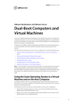
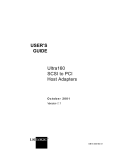
Figure 1.1 illustrates the format of the LSI Logic SDMS software.
Figure 1.1
The LSI Logic SDMS Software
.
Operating System
Supports
SDMS Storage Device Driver
SDMS Storage BIOS
Supports
LSI Logic Controller or
Processor
1.2 Overview
An LSI Logic SCSI controller or processor can control peripherals such
as hard disk drives, CD-ROM drives, tape drives, scanners, and
removable media. You can connect up to 15 wide (16-bit) SCSI
peripheral devices or seven 8-bit SCSI peripheral devices (by using the
SCSI bus) to a SCSI host adapter on which the SCSI controller or
processor resides.
1-2
Using the SDMS Software
Copyright © 1993–2001 by LSI Logic Corporation. All rights reserved.
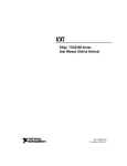
Figure 1.2 illustrates the flow of SDMS information within an operating
system.
Figure 1.2
SDMS Information Flow
.
Operating System
SDMS Storage Driver
SDMS Storage BIOS
LSI Logic Controller or
Processor
SCSI Bus
SCSI Peripherals
Overview
Copyright © 1993–2001 by LSI Logic Corporation. All rights reserved.
1-3
1.3 SDMS Device Drivers
The SDMS device drivers translate an operating system I/O request into
a SCSI request. Each SDMS SCSI device driver is operating system
specific and is designed to work on standard LSI Logic chip
implementations.
Currently, LSI Logic provides PCI to SCSI device drivers for the following
operating systems:
•
MS-DOS 6.0/Windows 3.1X
•
Windows 95, Windows 98, and Windows Me (Millennium Edition)
•
Windows NT - 4.0
•
Windows 2000
•
OS/2 - 4.XX
•
SCO OpenServer - Release 5.XX
•
UnixWare - 7
•
Solaris - 7 and 8
•
Linux
•
NetWare - 4.XX and 5.XX (NWPA)
This user’s guide provides device driver installation and configuration
instructions for each of these operating systems.
1.4 Basic Guidelines
Some basic rules for using SDMS software and installing a SCSI host
adapter device follow. The SDMS software requires an IBM PC/AT or
compatible computer with an 80486 or higher microprocessor. An
understanding of basic operating system commands is assumed. In
addition, users of this manual should have a general knowledge of the
SCSI standard.
Before using the SDMS software, you should configure the SCSI
controller into your system, taking into account the configuration of other
host adapters and system resources.
1-4
Using the SDMS Software
Copyright © 1993–2001 by LSI Logic Corporation. All rights reserved.
LSI Logic recommends that you back up all data before making any
changes or installing any software, including LSI Logic SCSI controllers
and software. Failure to adhere to this accepted computer practice may
lead to loss of data. You must terminate both ends of the SCSI bus.
Refer to the hardware manuals for the devices and users’ guides for the
host adapters to properly terminate the bus. Also you should locate
where jumpers or dip switches are for setting SCSI ID numbers. Usually,
the host adapter is ID 7. The devices are then set at IDs 0 through 6
(plus 8 through 15 for Wide SCSI). The bootable hard drive must have
the lowest numerical SCSI ID, unless you are able to use the BIOS Boot
Specification (BBS). Refer to Chapter 2 for additional information
regarding the BBS.
The red or blue line on a standard SCSI cable (or the black line on one
end of a multicolored SCSI cable) designates pin 1 on the cable
connector and must connect to pin 1 on the device and host adapter
connector. Refer to the hardware manuals for the devices and the
controller to locate pin 1 of the connector.
If the system already has an internal bootable hard drive (IDE, ESDI, or
ST506), the drivers for the SCSI device(s) must reside on the internal
bootable drive.
Basic Guidelines
Copyright © 1993–2001 by LSI Logic Corporation. All rights reserved.
1-5
1-6
Using the SDMS Software
Copyright © 1993–2001 by LSI Logic Corporation. All rights reserved.
Chapter 2
SCSI BIOS and
Configuration Utility
This chapter describes the SDMS SCSI BIOS and Configuration Utility.
It includes these topics:
•
Section 2.1, “Introduction,” page 2-1
•
Section 2.2, “Boot Initialization with BBS,” page 2-3
•
Section 2.3, “Using the SCSI BIOS Configuration Utility,” page 2-3
•
Section 2.4, “Starting the SCSI BIOS Configuration Utility,” page 2-4
•
Section 2.5, “Exiting the SCSI BIOS Configuration Utility,” page 2-22
2.1 Introduction
The SDMS SCSI BIOS is the bootable ROM code that manages SCSI
hardware resources. It is specific to a family of LSI Logic SCSI controllers
or processors. The SDMS SCSI BIOS integrates with a standard system
BIOS, extending the standard disk service routine provided through
INT13h.
During the boot time initialization, the SCSI BIOS determines if there are
other hard disks, such as an IDE drive, already installed by the system
BIOS. If there are, the SCSI BIOS maps any SCSI drives it finds behind
the drive(s) already installed. Otherwise, the SCSI BIOS installs drives
starting with the system boot drive. In this case, the system boots from
a drive controlled by the SCSI BIOS. For version 4.05.00 and higher,
LSI Logic supports the BIOS Boot Specification (BBS).
The next section, “Boot Initialization with BBS,” discusses selecting boot
and drive order.
PCI Storage Device Management System SDMS 4.0 User’s Guide
Copyright © 1993–2001 by LSI Logic Corporation. All rights reserved.
2-1
2.1.1 Features
The SDMS SCSI BIOS supports these features:
•
Configuration for up to 256 adapters-any 4 can be chosen for INT13h
(boot ROM) support
•
All LSI53C8XX devices including LSI53C895A
•
LSI53C1000 and LSI53C1010 devices
•
SPI-3 Parallel Protocol Request (PPR)
•
Domain Validation
2.1.2 LSI Logic Devices Supported
All LSI Logic devices and host adapters have undergone a name change.
They have transitioned from a SYM prefix to an LSI prefix. The SDMS
SCSI BIOS supports the following devices and their associated LSI Logic
host adapters:
2-2
•
LSI53C810, LSI53C810A, LSI53C810AE (LSI8100S, LSI8100ASP,
LSI20810)
•
LSI53C815 (LSI815XS, LSI8150SP)
•
LSI53C825, LSI53C825A (LSI8250S, LSI8251S, LSI8251D,
LSI8250ASP, LSI8251ASP, LSI8251AD)
•
LSI53C860, LSI53C860AE (LSI8600SP, LSI20860)
•
LSI53C875, LSI53C875E (LSI8750SP, LSI8751SP, LSI8751SPE,
LSI8751D)
•
LSI53C876 (LSI22801, LSI22802)
•
LSI53C885
•
LSI53C895 (LSI8951U, LSI8952U)
•
LSI53C895A (LSI8953U)
•
LSI53C896 (LSI22910, LSI21002, LSI22902)
•
LSI53C1000 (LSI20160, LSI20160L)
•
LSI53C1010 (ITI6200U3LP, LSI22915A, LSI21040, LSI22903,
LSI21003)
SCSI BIOS and Configuration Utility
Copyright © 1993–2001 by LSI Logic Corporation. All rights reserved.
2.2 Boot Initialization with BBS
The SDMS SCSI BIOS provides support for the BBS, which allows you
to choose which device to boot from by selecting the priority.
To use this feature, the system BIOS must also be compatible with the
BBS. If your system supports the BBS, then use the system BIOS setup
menu to select the boot and drive order. In the system BIOS setup, the
Boot Connection Devices menu appears with a list of available boot
options. Use that menu to select the device and rearrange the order.
Then exit saving changes to continue the boot process.
2.2.1 CD-ROM Boot Initialization
The SCSI BIOS supports boot initialization from a CD-ROM drive. The
five types of emulation are:
•
No emulation disk
•
Floppy 1.2 Mbyte emulation disk
•
Floppy 1.44 Mbyte emulation disk
•
Floppy 2.88 Mbyte emulation disk
•
Hard disk emulation
The type of emulation determines the drive letter assignment for the
CD-ROM. For example, if you load a 1.44 Mbyte floppy emulation
CD-ROM, then the CD-ROM drive would become the designated A:
drive, and the existing floppy would become drive B:.
2.3 Using the SCSI BIOS Configuration Utility
This section provides the menu formats and user inputs available to
inform all users about this utility prior to running it. All SCSI BIOS
Configuration Utility screens that display various menus are partitioned
into fixed areas. This area provides static general help text information.
Boot Initialization with BBS
Copyright © 1993–2001 by LSI Logic Corporation. All rights reserved.
2-3
2.3.1 User Inputs
You make configuration changes in the main area of the menu. As in the
example menus, it is lighter in color than the header or footer areas.
Table 2.1 lists the various keyboard options you use to make changes.
Settings with grey or yellow text can be changed, settings with white text
cannot. This is true regardless of the Color/Mono setting chosen.
Table 2.1
Keyboard Options
Keyboard Options
Description
F1 = Help
Provides context sensitive help for the cursor
resident field.
F2 = menu
Sets cursor context to the menu Area. Select a
menu item and press Enter. This option is only
available from the Main menu.
Arrow Keys = Select
Item
Move the cursor up, down, left, or right.
+/− = Change [Item]
Changes items with values in [ ] brackets. Use the
‘+’ and ‘−’ keys in the top row of the main keyboard
or use the numeric keypad ‘+’ and ‘−’ keys to change
values. When pressed, they toggle a modifiable field
to its next relative value. ‘+’ toggles the value up and
‘−’ toggles the value down.
Esc = Abort/Exit
Aborts the current context operation and/or exits the
current screen. This option calls an Exit menu,
described further in Section 2.5, “Exiting the SCSI
BIOS Configuration Utility,” page 2-22.
Home/End = Select Item Moves the cursor to the start/end of a scrollable
field.
Enter = Execute <Item>
Executes options with values in < > brackets. Press
Enter to execute the field’s associated function.
2.4 Starting the SCSI BIOS Configuration Utility
If you have SCSI BIOS version 4.XX, and it includes the SDMS SCSI
BIOS Configuration Utility, you can change the default configuration of
your SCSI host adapters. You may decide to alter these default values if
2-4
SCSI BIOS and Configuration Utility
Copyright © 1993–2001 by LSI Logic Corporation. All rights reserved.
there is a conflict between device settings or if you need to optimize
system performance.
You can see the version number of your SCSI BIOS in a banner
displayed on your computer monitor during boot. If the utility is available,
the following message also appears on your monitor:
Press Ctrl-C to start LSI Logic Configuration Utility...
This message remains on your screen for about five seconds, giving you
time to start the utility. If you decide to press Ctrl-C, the message
changes to:
Please wait invoking LSI Logic Configuration Utility...
After a brief pause, your computer monitor displays the Main menu of the
SCSI BIOS Configuration Utility.
The following messages may appear during the boot process:
•
Adapter removed from boot order, parameters will be updated
accordingly! appears when an adapter is removed from the system
or relocated behind a PCI bridge.
•
Configuration data invalid, saving default configuration!
appears if none of the information in NonVolatile Random Access
Memory (NVRAM) is valid.
•
Found SCSI Controller not in following Boot Order List, to
Add: Press Ctrl-C to start LSI Logic Configuration
Utility... or Adapter configuration may have changed,
reconfiguration is suggested! could appear when fewer than four
adapters are in the boot order and adapters exist in the system which
are not in the boot order.
The SDMS SCSI BIOS does not control all devices detected by this
configuration utility. Devices such as tape drives and scanners require
that a device driver specific to that peripheral be loaded.
To make changes with this menu-driven utility, one or more LSI Logic
SCSI host adapters must have NVRAM to store the changes. You can
change four sets of configurations. You make changes on subordinate
menus called from the Main menu, which is opened when you start the
SCSI BIOS Configuration Utility. The subordinate menus are:
Starting the SCSI BIOS Configuration Utility
Copyright © 1993–2001 by LSI Logic Corporation. All rights reserved.
2-5
•
Adapter Properties
•
Device Properties
•
Boot Adapter List
•
Global Properties
All of these properties are controlled by menus you access through the
SCSI BIOS Configuration Utility’s Main menu. The Main menu also gives
an overview of some properties of installed LSI Logic host adapter
boards.
Important:
The SCSI BIOS Configuration Utility is a powerful tool.
While using it, if you somehow disable all of your
controllers, press Ctrl-A (or Ctrl-E on version 4.04 or
later) after memory initialization during reboot. This will
allow you to re-enable and reconfigure your controllers.
Also, if the system locks up due to NonVolatile Storage
(NVS), press Ctrl-N to bypass the BIOS in order to
reflash the card.
2.4.1 Accessing the Configuration Utility Main Menu
After invoking the SCSI BIOS Configuration Utility, the Main menu
appears and displays a list of up to 256 PCI to SCSI host adapters in
the system and information about each of them. To select an adapter,
use only the arrow keys and enter key. The system scans the adapter’s
SCSI bus after selecting an adapter.
Only adapters with LSI Logic Control enabled can be accessed. Adapters
without NonVolatile Memory (NVM) display default settings and cannot
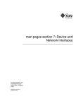
be changed. Figure 2.1 illustrates this menu.
2-6
SCSI BIOS and Configuration Utility
Copyright © 1993–2001 by LSI Logic Corporation. All rights reserved.
Figure 2.1
Main Menu
LSI Logic SDMS (TM) PCI SCSI Configuration Utility Version PCI-4.XX.00
<Boot Adapter List>
<Global Properties>
LSI53C8XX Host Bus Adapters
Adapter
PCI
Bus
Dev/
Func
Port
Number
IRQ
NVM
Boot
Order
LSI Logic
Control
<53C1010-66
0
60>
E400
9
Yes
1
Enabled
<53C1010-66
0
61>
E000
10
Yes
0
Enabled
<53C895
0
58>
FC00
11
Yes
2
Enabled
F1 =Help
ΑrrowKeys=Select Item
-/+
Esc=Abort/Exit
Home/End =Select Item
Enter=Execute <Item>
=Change [Item]
F2 =Menu
Starting the SCSI BIOS Configuration Utility
Copyright © 1993–2001 by LSI Logic Corporation. All rights reserved.
2-7
Table 2.2 lists the fields on this menu and their descriptions.
Table 2.2
Main Menu Fields and Descriptions
Fields
Field Type
[Value]
Adapter
Information
Indicates the specific LSI Logic family of host adapters. Clicking on an
entry under Adapter will lead to the Adapter Properties menu.
PCI Bus
Information
Indicates the PCI bus number (range 0x00–0xFF, 0–255 decimal) assigned
by the system BIOS to an adapter.
Dev/Func
Information
Indicates the PCI Device/Function assigned by the system BIOS to an
adapter.
An 8-bit value is mapped as follows:
Descriptions
Bit # 7 6 5 4 3 2 1 0
Bits [7:3]: Device (range 0x00–0x1F, 0–31 decimal)
Bits [2:0]: Function (range [0–7])
Port
Number
Information
Indicates the I/O port number that communicates with an adapter, which
the system BIOS assigns.
IRQ
Information
Indicates the Interrupt Request Line used by an adapter, which is assigned
by the system BIOS.
NVM
Information
Indicates whether an adapter has NVM associated with it. An adapter's
configuration is stored in its associated NVM. NVM can refer to NVRAM
that is resident on a host adapter or to system NVS.
Boot Order Information
Indicates the relative boot order (0 to 3) of an adapter. The SDMS SCSI
BIOS traverses up to four adapters in the specified order in search of
bootable media. To modify this field, access the Boot Adapter List menu.
LSI Logic
Control
Indicates whether an adapter is eligible for LSI Logic software control or is
reserved for control by non-LSI Logic software.
Information
Below the header area of the Main menu, the Boot Adapter List and
Global Properties options are available for you to configure their host
adapters. The Boot Adapter List allows selection and ordering of boot
adapters. Global Properties allow changes to global scope settings.
Refer to Section 2.4.4, “Boot Adapter List Menu,” page 2-17 and Section
2.4.5, “Global Properties Menu,” page 2-20 for more detailed information.
2-8
SCSI BIOS and Configuration Utility
Copyright © 1993–2001 by LSI Logic Corporation. All rights reserved.
2.4.2 Adapter Properties Menu
The Adapter Properties menu allows you to view and modify adapter
settings and SCSI devices connected to it. It also provides access to an
adapter's device settings. To display this menu, select a device under
Adapter field on the Main menu and press Enter. Figure 2.2 illustrates the
Adapter Properties menu.
Figure 2.2
Adapter Properties Menu
LSI Logic SDMS (TM) PCI SCSI Configuration Utility Version PCI-4.XX.00
Adapter Properties
Adapter
53C895
PCI
Dev/
Bus
Func
0
60
<Device Properties>
SCSI Parity
[Yes]
Host SCSI ID
[7]
SCSI Bus Scan Order
[Low to High (0..Max)]
Removable Media Support [None]
CHS Mapping
[SCSI Plug and Play Mapping]
Spinup Delay (Secs)
[2]
Secondary Cluster
Server
[No]
Termination Control
[Auto]
<Restore Defaults>
F1 =Help
ΑrrowKeys=Select Item
-/+ =Change [Item]
Esc=Abort/Exit
Home/End =Select Item
Enter=Execute <Item>
Starting the SCSI BIOS Configuration Utility
Copyright © 1993–2001 by LSI Logic Corporation. All rights reserved.
2-9
Table 2.3 lists the fields on this menu and their descriptions.
Note:
Table 2.3
If the field displays in grey or yellow text it is available for
changes. If it displays in white text it is not available.
Adapter Properties Menu Fields and Descriptions
Field
Field Type
[Value]
Descriptions
Device
Properties
Executable
Select this option and press Enter to view and modify device
properties.
SCSI Parity
Configuration
[Yes/No]
Indicates whether SCSI parity is enabled for an adapter. When
disabled, you must disable disconnects for all devices, as parity
checking for the reselection phase is not disabled. If a nonparity
generating device disconnects, its operation will never complete
because the reselection fails due to parity error.
Host SCSI ID
Configuration
[0 to 7/0 to 15]
Indicates the SCSI identifier of an adapter. LSI Logic
recommends that this field be set to the highest priority SCSI
identifier, which is 7.
SCSI Bus
Scan Order
Configuration
[Low to High (0
.. Max)/High to
Low (Max .. 0)]
Indicates the order in which to scan SCSI identifiers on an
adapter. Changing this item will affect drive letter assignment(s)
if more than one device is attached to an adapter.
Removable
Media
Support
Configuration
[None/Boot
Drive Only/
With Media
Installed]
Specifies the removable media support option for an adapter.
Removable media support only applies to devices that report
themselves as a hard drive. It does not apply to CD-ROM
devices or Magnetic Optical devices.
None indicates no removable media support whether the drive is
selected as first (BBS), or is first in the scan order (non-BBS).
Boot Drive Only provides removable media support for a
removable hard drive if it is first in the scan order.
With Media Installed provides removable media support
regardless of the drive number assignment. You must have
media in the drive at bootup.
2-10
SCSI BIOS and Configuration Utility
Copyright © 1993–2001 by LSI Logic Corporation. All rights reserved.
Table 2.3
Adapter Properties Menu Fields and Descriptions (Cont.)
Field
Field Type
[Value]
Descriptions
CHS Mapping
Configuration
[SCSI Plug and
Play Mapping/
Alternate CHS
Mapping]
Defines how the Cylinder Head Sector (CHS) values are mapped
onto a disk without pre-existing partition information.
SCSI Plug and Play Mapping automatically determines the most
efficient and compatible mapping.
Alternate CHS Mapping utilizes an alternate, possibly less
efficient mapping that may be required if a device is moved
between adapters from different vendors.
Caution: Neither of these options has any effect after a disk has
been partitioned using the FDISK command. The FDISK utility
is a tool that you can use to delete partition entries, one or all of
them. If all partition entries are deleted, it is necessary to reboot
to clear memory or the old partitioning data will be reused, thus
nullifying the previous operation. Use care to ensure that the
correct disk is the target of an FDISK command.
Spinup Delay
(secs)
Configuration
[1 to 15]
Secondary
Configuration
Cluster Server [Yes/No]
Indicates the delay in seconds between spinups of devices
attached to an adapter. Staggered spinups balance the total
electrical current load on the system during boot. The default
value is 2 seconds.
Indicates whether an adapter has one or more devices attached
that are shared with one or more other adapters. Therefore, the
SDMS SCSI BIOS should avoid SCSI bus resets as much as
possible.
This option allows you to enable an adapter to join a cluster of
adapters without doing any SCSI bus resets. This is a
requirement for the Microsoft Cluster Server. The default value is
No with an alternate option of Yes.
Termination
Control
Configuration
[Auto/Off]
If available, the field Indicates whether an adapter has automatic
termination control. If not available, its current status is either
Auto or Off.
Auto means that the adapter automatically can determine
whether it should enable or disable its termination.
Off means termination on the adapter is off and the devices at
the ends of the SCSI bus must terminate the bus.
Restore
Defaults
Executable
Press Enter to obtain default settings.
Starting the SCSI BIOS Configuration Utility
Copyright © 1993–2001 by LSI Logic Corporation. All rights reserved.
2-11
2.4.3 Device Properties Menu
The Device Properties menu allows you to view and update individual
device settings for an adapter. Changing a setting for the host device (for
example, SCSI ID 7) changes the setting for all devices. The number of
fields displayed requires the menu to scroll left/right in order to display
the information. When accessing this menu online, use the Home/End
keys to scroll to columns currently not displayed. The scroll indicator on
the bottom of the menu shows where the cursor is relative to the first and
last columns. The example for the Device Properties menu is split
(Figure 2.3 and Figure 2.4) due to the width of its multiple fields/columns.
2-12
SCSI BIOS and Configuration Utility
Copyright © 1993–2001 by LSI Logic Corporation. All rights reserved.
Figure 2.3
Device Properties Menu (Left Half)
LSI Logic SDMS (TM) PCI SCSI Configuration Utility Version PCI-4.XX.00
Device Properties
SCSI Device Identifier
ID
MB/Sec
MT/Sec
Data
Width
Scan
ID
Scan
LUNs>0
Disconnect
0
Quantum Viking 4.5
[160]
[80]
[16]
[Yes]
[Yes]
[On]
1
Quantum Viking 4.5
[160]
[80]
[16]
[Yes]
[Yes]
[On]
2
Quantum Viking 4.5
[160]
[80]
[16]
[Yes]
[Yes]
[On]
3
Quantum Viking 4.5
[160]
[80]
[16]
[Yes]
[Yes]
[On]
4
Quantum Viking 4.5
[160]
[80]
[16]
[Yes]
[Yes]
[On]
5
Quantum Viking 4.5
[160]
[80]
[16]
[Yes]
[Yes]
[On]
6
-
[160]
[80]
[16]
[Yes]
[Yes]
[On]
7
53C895
[160]
[80]
[16]
[Yes]
[Yes]
[On]
8
-
[160]
[80]
[16]
[Yes]
[Yes]
[On]
9
-
[160]
[80]
[16]
[Yes]
[Yes]
[On]
10
-
[160]
[80]
[16]
[Yes]
[Yes]
[On]
11
-
[160]
[80]
[16]
[Yes]
[Yes]
[On]
12
-
[160]
[80]
[16]
[Yes]
[Yes]
[On]
13
-
[160]
[80]
[16]
[Yes]
[Yes]
[On]
14
-
[160]
[80]
[16]
[Yes]
[Yes]
[On]
15
-
[160]
[80]
[16]
[Yes]
[Yes]
[On]
F1 =Help
ArrowKeys=Select Item
-/+ =Change [Item]
Esc=Abort/Exit
Home/End =Select Item
Enter=Execute <Item>
Starting the SCSI BIOS Configuration Utility
Copyright © 1993–2001 by LSI Logic Corporation. All rights reserved.
2-13
Figure 2.4
Device Properties Menu (Right Half)
LSI Logic SDMS (TM) PCI SCSI Configuration Utility Version PCI-4.XX.00
Device Properties
SCSI Device Identifier
ID
SCSI
Timeout
Queue
Tags
Boot
Format
Choice
Verify
Restore
Defaults
0
Quantum Viking 4.5 < 10>
[On]
[No]
[Format] [Verify] <Defaults>
1
Quantum Viking 4.5 < 10>
[On]
[No]
[Format] [Verify] <Defaults>
2
Quantum Viking 4.5 < 10>
[On]
[No]
[Format] [Verify] <Defaults>
3
Quantum Viking 4.5 < 10>
[On]
[No]
[Format] [Verify] <Defaults>
4
Quantum Viking 4.5 < 10>
[On]
[No]
[Format] [Verify] <Defaults>
5
Quantum Viking 4.5 < 10>
[On]
[No]
[Format] [Verify] <Defaults>
6
-
< 10>
[On]
[No]
[Format] [Verify] <Defaults>
7
53C895
< 10>
[On]
[No]
[Format] [Verify] <Defaults>
8
-
< 10>
[On]
[No]
[Format] [Verify] <Defaults>
9
-
< 10>
[On]
[No]
[Format] [Verify] <Defaults>
10
-
< 10>
[On]
[No]
[Format] [Verify] <Defaults>
11
-
< 10>
[On]
[No]
[Format] [Verify] <Defaults>
12
-
< 10>
[On]
[No]
[Format] [Verify] <Defaults>
13
-
< 10>
[On]
[No]
[Format] [Verify] <Defaults>
14
-
< 10>
[On]
[No]
[Format] [Verify] <Defaults>
15
-
< 10>
[On]
[No]
[Format] [Verify] <Defaults>
F1 =Help
ArrowKeys=Select Item
-/+ =Change [Item]
Esc=Abort/Exit
Home/End =Select Item
Enter=Execute <Item>
2-14
SCSI BIOS and Configuration Utility
Copyright © 1993–2001 by LSI Logic Corporation. All rights reserved.
Table 2.4 lists the fields on this menu and their descriptions.
Table 2.4
Device Properties Menu Fields and Descriptions
Field
Field Type
[Value]
Description
SCSI ID
Information
Displays the device’s SCSI identifier.
Device
Identifier
Information
Indicates the ASCII device identifier string, as extracted from the
device’s inquiry data.
MB/Sec
Information
[0/5/10/20/40/
80/160]
Indicates the maximum synchronous data transfer rate of the
adapter in megabytes per second corresponding to the width and
transfer rate settings that follow.
MT/Sec
Configuration
[0/5/10/20/40/
80]
Indicates the maximum synchronous data transfer rate of the
adapter in megatransfers per second. Can be changed to a lower
transfer rate.
Data Width
Configuration
[8/16]
Displays the maximum data width of the adapter in bits. Can be
changed to narrower, if available.
Scan ID
Configuration
[Yes/No]
Indicates whether to scan for this SCSI identifier at boot time.
Utilizing this setting allows you to ignore a device. This decreases
boot time by disabling inquiry of unused SCSI identifiers.
Set this option to No if there is a device that you do not want to
be available to the system. Also, on a bus with only a few devices
attached, you can speed up boot time by changing this setting to
No for all unused SCSI IDs.
Scan LUNs > 0 Configuration
[Yes/No]
Indicates whether to scan for Logical Unit Numbers (LUNs) greater
than zero for a device. LUN 0 is always queried. Use this option if
a multi-LUN device responds to unoccupied LUNs or if it is desired
to reduce the visibility of a multi-LUN device to LUN 0 only.
Set this option to No if you have problems with a device that
responds to all LUNs whether they are occupied or not. Also, if a
SCSI device with multiple LUNs exists on your system but you do
not want all of those LUNs to be available to the system, then set
this option to No. This will limit the scan to LUN 0.
Disconnect
Configuration
[On/Off]
Indicates whether to allow a device to disconnect during SCSI
operations. Some (usually newer) devices run faster with
disconnect enabled, while some (usually older) devices run faster
with disconnect disabled.
Starting the SCSI BIOS Configuration Utility
Copyright © 1993–2001 by LSI Logic Corporation. All rights reserved.
2-15
Table 2.4
Device Properties Menu Fields and Descriptions (Cont.)
Field
Field Type
[Value]
Description
SCSI Timeout
Executable
[0–9999]
Indicates the maximum allowable time for completion of a SCSI
operation in seconds. Since timeouts provide a safeguard that
allows the system to recover should an operation fail, LSI Logic
recommends that a value greater than zero be used. A value of
zero allows unlimited time for an operation to complete and could
result in the system hanging (waiting forever) should an operation
fail.
Note: This field is executable and must be selected with the Enter
key. You also input the new value with the number keys from either
the keyboard or number pad.
Queue Tags
Configuration
[On/Off]
Indicates whether to allow the use of queue tags for a device.
Currently the BIOS does not use queue tags. This item specifies
queue tag control to higher level device drivers.
Boot Choice
Configuration
[Yes/No]
Indicates whether this device can be selected as the boot device.
This option is only applicable to devices attached to adapter
number zero in the boot list on non-BBS systems. It provides
primitive BBS flexibility to non-BBS systems.
Format
Executable
Allows low-level formatting on a disk drive, if enabled. Low-level
formatting will completely and irreversibly erase all data on the
drive. To low level format a device, select the device from the
menu and use the arrow keys to move the cursor to the Format
column. Press Enter.
Note: Formatting will default the drive to a 512-byte sector size
even if the drive had previously been formatted to another sector
size.
Verify
Executable
Allows verification of all sectors on a device and reassigns
defective Logical Block Addresses (LBAs), if enabled. To verify all
sectors, select the device from the menu and use the arrow keys
to move the cursor to the Verify column. Press Enter.
Restore
Defaults
Executable
Press Enter to obtain default settings.
2-16
SCSI BIOS and Configuration Utility
Copyright © 1993–2001 by LSI Logic Corporation. All rights reserved.
2.4.4 Boot Adapter List Menu
The Boot Adapter List menu specifies the order in which adapters boot
when more than one LSI Logic host adapter is in a system. Up to four
of the total adapters in a system can be selected as bootable. To control
a Boot Volume, only one of the four “active” controllers can be used.
To select this menu:
1. Press F2 while on the Main menu to move the cursor to the menu
Area.
2. Move the cursor to Boot Adapter List with the arrow keys.
3. Press Enter.
Adapters can be added or deleted using this menu. To add an adapter
to the boot list, press the Insert key while on the Boot Adapter List. Use
the arrow keys to select the desired adapter and press Enter to add it to
the end of the Boot Adapter List.
To remove an adapter from the boot list, press the Delete key while on
the desired adapter in the Boot Adapter List. You can also change the
boot order by using the “+” or “−” keys. For example, place the cursor on
the adapter that you want to change, and use the “+” or “−” key to raise
or lower the boot order.
Starting the SCSI BIOS Configuration Utility
Copyright © 1993–2001 by LSI Logic Corporation. All rights reserved.
2-17
Figure 2.5 illustrates the Boot Adapter List menu.
Figure 2.5
Boot Adapter List Menu
LSI Logic SDMS (TM) PCI SCSI Configuration Utility Version PCI-4.XX.00
Boot Adapter List
Insert=Add an adapter
Adapter
Delete=Remove an adapter
PCI
Bus
Dev/
Func
Boot
Order
Current
Status
Next
Boot
53C895
0
98
[2]
Off
[On]
53C1010-66
0
60
[0]
On
[On]
53C1010-66
0
61
[1]
On
[On]
Hit Insert to select an adapter from this list.
<53C895
0
98>
<53C1010-66
0
60>
<53C1010-66
0
61>
F1=Help
Esc=Abort/Exit
2-18
ArrowKeys=Select Item
Home/End =Select Item
-/+
=Change [Item]
Enter=Execute <Item>
SCSI BIOS and Configuration Utility
Copyright © 1993–2001 by LSI Logic Corporation. All rights reserved.
Table 2.5 lists the fields on this menu and their descriptions.
Table 2.5
Boot Adapter List Menu Fields and Descriptions
Field
Field Type
[Value]
Description
Adapter
Information
Indicates the specific LSI Logic family of host adapters.
PCI Bus
Information
Indicates the PCI bus number (range 0x00–0xFF, 0–255 decimal)
assigned by the system BIOS to an adapter.
Dev/Func
Information
Indicates the PCI Device/Function assigned by the system BIOS to an
adapter.
An 8-bit value is mapped as follows:
Bit # 7 6 5 4 3 2 1 0
Bits [7:3]: Device (range 0x00–0x1F, 0–31 decimal)
Bits [2:0]: Function (range 0–7)
Boot Order
Configuration Indicates the relative boot order (0 to 3) of the listed adapter. The SDMS
[0 to 3]
SCSI BIOS traverses up to four adapters in the specified order in search
of bootable media.
Current
Status
Information
Next Boot
Configuration Indicates whether to enable an adapter upon the next boot. The SDMS
[On/Off]
SCSI BIOS ignores disabled adapters and their attached devices
although they are still visible to the configuration utility.
Indicates whether an adapter in the boot list was enabled during the most
recent boot. The SDMS SCSI BIOS ignores disabled adapters and their
attached devices, although they are still visible to the configuration utility.
Starting the SCSI BIOS Configuration Utility
Copyright © 1993–2001 by LSI Logic Corporation. All rights reserved.
2-19
2.4.5 Global Properties Menu
The Global Properties menu allows you to view boot information and to
set display and video modes. Figure 2.6 illustrates the Global Properties
menu. Table 2.6 lists the fields and their descriptions.
Figure 2.6
Global Properties Menu
LSI Logic SDMS (TM) PCI SCSI Configuration Utility Version PCI-4.XX.00
Global Properties
Pause When Boot Alert
Displayed
[No]
Boot Information Display
Mode
[Verbose]
Negotiate with devices
[Supported]
Language
[English]
Video Mode
[Color]
Support Interrupt
[Hook Interrupt, the Default]
<Restore Defaults>
F1 =Help
ArrowKeys=Select Item
-/+
Esc=Abort/Exit
Home/End=Select Item
Enter=Execute <Item>
2-20
SCSI BIOS and Configuration Utility
Copyright © 1993–2001 by LSI Logic Corporation. All rights reserved.
=Change [Item]
Table 2.6
Global Properties Fields and Descriptions
Field
Field Type
[Value]
Description
Pause When Boot
Alert Displayed
Configuration
[Yes/No]
Specifies a pause during the boot for user
acknowledgement. The pause occurs after displaying
an alert message.
To continue after displaying a message, specify No.
To wait for any key after displaying a message, specify
Yes.
Boot Information
Display Mode
Configuration
[Terse/Verbose]
Specifies how much BIOS information displays during
boot.
To display minimum information, specify Terse mode.
To display detailed information, specify Verbose mode.
Negotiate with
Devices
Configuration
Sets the default value for synchronous and wide
[All, None, Supported] negotiations with specified devices.
Language
Configuration
This option specifies the current language set for using
this utility.
Video Mode
Configuration
[Color/Monochrome]
Specifies the default video mode for the SCSI BIOS
Configuration Utility. The monochrome setting
enhances readability on a monochrome monitor.
Support Interrupt
Configuration for BBS
Systems
[Hook Interrupt, the
default/Bypass
Interrupt Hook]
This option allows the ability to prevent a hook on
INT40h, if required. The two settings are: Hook
Interrupt, the default, and Bypass Interrupt Hook.
Fixed for non-BBS
systems
Hook Interrupt is the normal operation that supports
booting CD-ROMs in floppy emulation mode on most
machines.
On certain platforms, the system BIOS uses the
INT40h interrupt chain in a nonstandard way. On these
platforms, you should use the "Bypass Interrupt Hook"
setting. This setting prevents a hook into the INT40h
chain. If the "Bypass Interrupt Hook" setting is used on
systems that do not require it, the CD-ROM may fail to
boot and an error message may appear and indicate it
is unable to read the boot device.
Note:Try toggling this value if your machine fails to
boot a CD-ROM in floppy emulation mode.
Restore Defaults
Executable
Press Enter to obtain default settings.
Starting the SCSI BIOS Configuration Utility
Copyright © 1993–2001 by LSI Logic Corporation. All rights reserved.
2-21
2.5 Exiting the SCSI BIOS Configuration Utility
The Exit menu for the SCSI BIOS Configuration Utility is used for all five
of the menus listed above. However, the available functionality is different
for the Main menu and the four subordinate menus. Figure 2.7 illustrates
the Exit menu.
Figure 2.7
Exit Menu
LSI Logic SDMS (TM) PCI SCSI Configuration Utility Version PCI-4.XX.00
Adapter and/or device property changes have been made
<Cancel exit>
Exit the Configuration Utility
<Save changes then exit this menu>
<Discard changes then exit this menu>
To exit from the Adapter Properties, Device Properties, Boot Adapter List,
or Global Properties menus, use these exit options:
Cancel exit
This option returns you to the previous menu.
Save changes then
exit this menu
This option implements any changes you made on the
previous menu and returns you to the Main menu.
Discard changes then This option restores the default settings and returns you
exit this menu
to the Main menu.
To exit from the Main menu, use these exit options:
Cancel exit
This returns you to the Main menu.
Exit the Configuration This option exits the configuration and automatically
Utility
reboots your system.
Important:
2-22
If you reboot the system without properly exiting from this
utility, some changes may not take effect.
SCSI BIOS and Configuration Utility
Copyright © 1993–2001 by LSI Logic Corporation. All rights reserved.
Chapter 3
Windows 95, Windows
98, Windows Me Device
Driver Installation
This chapter describes the device drivers for the Windows 95, Windows
98, and Windows Me operating systems. It provides installation
instructions for new and existing system installations and includes these
topics:
•
Section 3.1, “Introduction,” page 3-1
•
Section 3.2, “Using the SYMC8XX/SYM_HI/SYM_U3 Drivers,”
page 3-4
•
Section 3.3, “Installing Drivers for Windows 95/98/Me,” page 3-5
•
Section 3.4, “Troubleshooting,” page 3-13
•
Section 3.5, “Using the Command Line Options,” page 3-14
•
Section 3.6, “Using SCSI Tools for Windows 95/98,” page 3-20
3.1 Introduction
Windows 95, Windows 98, and Windows Millennium Edition (Me) are
operating systems designed to run on Intel processors using current
technology. This chapter refers to Windows 95, Windows 98, and
Windows Me as Windows 95/98/Me in many instances.
Windows 95/98/Me provides a graphical user interface (GUI)
environment incorporating many high-level features. Refer to the
Microsoft Windows 95/98/Me documentation for more details. An I/O
manager handles I/O requests by going through the appropriate drivers
to address a SCSI peripheral.
Windows 95/98/Me provides class drivers for hard disk, floptical,
CD-ROM, printer, and scanner peripherals. Other class drivers, provided
by peripheral manufacturers, are added to support new devices.
Microsoft provides the port driver and LSI Logic provides the miniport
drivers, which are called SYMC8XX.MPD, SYM_HI.MPD, and SYM_U3.MPD.
PCI Storage Device Management System SDMS 4.0 User’s Guide
Copyright © 1993–2001 by LSI Logic Corporation. All rights reserved.
3-1
These drivers complete the path to an LSI Logic controller or processor
with an optional SDMS SCSI BIOS.
LSI Logic uses the same filenames for their drivers for different Windows
operating systems. The driver files are packaged either in separate
subdirectories based on the Windows operating system or on different
flex disks. To determine the driver file for Windows 95/98/Me, note that
the filename ends with .MPD. The following sections describe these
drivers and their installation.
3.1.1 Features
The SDMS device drivers for Windows 95/98/Me support these features:
•
Ultra160 data transfers (for LSI53C1000 and LSI53C1010)
•
Domain Validation (for the SYM_U3.MPD driver only)
•
Parallel Protocol Request (PPR) (for the SYM_U3.MPD driver only)
•
Cyclic Redundancy Check (CRC) (for the SYM_U3.MPD driver only)
•
Synchronous negotiation (including Fast SCSI, Ultra SCSI, Ultra2 SCSI)
•
Wide negotiation
•
Auto Request Sense
•
Multiple host adapters
•
Multiple LUNs
•
Disconnect/Reselect
•
Scatter/Gather
•
Differential support
•
SCSI pass-through functionality
•
SCSI Configured AutoMatically (SCAM)
•
Target Initiated Negotiation (TIN)
•
NVRAM (wide/sync parameters, SCSI Host ID, SCAM on/off)
3.1.2 LSI Logic Devices Supported
All LSI Logic devices and host adapters have undergone a name change.
They have transitioned from a SYM prefix to an LSI prefix. No name
changes have occurred for the SDMS Windows 95/98/Me drivers.
3-2
Windows 95, Windows 98, Windows Me Device Driver Installation
Copyright © 1993–2001 by LSI Logic Corporation. All rights reserved.
The SYMC8XX.MPD driver supports the following devices and their
associated LSI Logic host adapters:
•
LSI53C810, LSI53C810A, LSI53C810AE (LSI8100S, LSI8100ASP,
LSI20810)
•
LSI53C815 (LSI815XS, LSI8150SP)
•
LSI53C825, LSI53C825A (LSI8250S, LSI8251S, LSI8251D,
LSI8250ASP, LSI8251ASP, LSI8251AD)
•
LSI53C860, LSI53C860AE (LSI8600SP, LSI20860)
•
LSI53C875, LSI53C875E (LSI8750SP, LSI8751SP, LSI8751SPE,
LSI8751D)
•
LSI53C876, LSI53876E (LSI22801, LSI22802)
•
LSI53C885
•
LSI53C895 (LSI8951U, LSI8952U)
The SYM_HI.MPD driver supports the following devices and their
associated LSI Logic host adapters:
•
LSI53C895A (LSI8953U)
•
LSI53C896 (LSI22910, LSI21002, LSI22902)
The SYM_U3.MPD driver supports the following devices and their
associated LSI Logic host adapters:
•
LSI53C1000 (LSI20160, LSI20160L)
•
LSI53C1010 (LSI22915A, LSI22903, LSI21040, LSI21003,
ITI6200U3LP).
3.1.3 Description
The SYMC8XX.MPD, SYM_HI.MPD, and SYM_U3.MPD drivers conform to the
Microsoft specification for miniport drivers. These drivers allow
connection of SCSI devices including disk drives, CD-ROMs, and tape
drives for PCI-based machines. To support a new SCSI device,
Windows 95/98/Me architecture requires that a class driver for that type
of device be present. These are usually supplied by Microsoft, or possibly
by the peripheral manufacturer. No changes to SYMC8XX.MPD,
SYM_HI.MPD, or SYM_U3.MPD are required. These drivers are only
supported under Windows 95/98/Me.
Introduction
Copyright © 1993–2001 by LSI Logic Corporation. All rights reserved.
3-3
A Windows application passes SCSI commands directly to the SCSI
devices by using the SCSI pass-through facility. Refer to Microsoft
Windows 95/98/Me documentation for more details. This facility allows
applications to directly control and access SCSI devices by filling in a
data structure and calling into the port driver.
The SYMC8XX.MPD and SYM_HI.MPD drivers support Ultra SCSI protocol,
providing twice the raw data transfer rate of Fast SCSI for disk drives and
LSI Logic host adapters that support Ultra SCSI. These drivers also
support Ultra2 SCSI protocol, providing quadruple the raw data transfer
rate of Fast SCSI.
The SYM_U3.MPD driver supports Ultra160 SCSI protocol providing up to
160 Mbytes/s data transfer for double transition. Ultra160 also includes
CRC, PPR, and Domain Validation. The standard Ultra160 SCSI protocol
performs 80 megatransfers per second resulting in approximately double
the synchronous data transfer rates of Ultra2 SCSI.
Caution:
Ultra SCSI requires more stringent SCSI bus cabling
setups than Fast SCSI. Ultra2 SCSI and Ultra160 SCSI
require Low Voltage Differential (LVD) termination.
3.2 Using the SYMC8XX/SYM_HI/SYM_U3 Drivers
The SDMS Software Device Driver and Utilities CD-ROM contains the
SYMC8XX.MPD, SYM_HI.MPD, and SYM_U3.MPD drivers and their associated
files in this directory:
{CD-ROM Drive Letter}:\DRIVERS\WIN9X
You must prepare an SDMS Driver Diskette before proceeding with the
installation instructions.
3.2.1 Preparing an SDMS Driver Diskette
Copy the files listed in this section to the root directory of a clean
diskette. Various subdirectories contain the appropriate driver files. You
will use this SDMS driver diskette during installation.
For the SYMC8XX.MPD driver, locate the files at:
{CD-ROM Drive Letter}:\DRIVERS\WIN9X\8XX9X.
3-4
Windows 95, Windows 98, Windows Me Device Driver Installation
Copyright © 1993–2001 by LSI Logic Corporation. All rights reserved.
•
SYMC8XX.MPD
•
SYMC8XX.INF
For the SYM_HI.MPD driver, locate the files at:
{CD-ROM Drive Letter}:\DRIVERS\WIN9X\WIN9XHI.
•
SYM_HI.MPD
•
SYM_HI.INF
For the SYM_U3.MPD driver, locate the files at:
{CD-ROM Drive Letter}:\DRIVERS\WIN9X\9XULTRA3
•
SYM_U3.MPD
•
SYM_U3.INF
You may also obtain the Windows 95/98/Me drivers from the LSI Logic
web site at: http://www.lsilogic.com. After you are connected to this
web site, place your cursor on the Get Drivers option in the menu bar.
Click on the Drivers selection. Choose the Windows 95/98/Me operating
system for SCSI and click on the Go button. Follow the instructions on
subsequent screens to download the drivers.
3.3 Installing Drivers for Windows 95/98/Me
This section provides installation instructions for new and existing
Windows 95/98/Me systems.
3.3.1 New System Installation
Use this procedure to install the SYMC8XX.MPD, SYM_HI.MPD, or
SYM_U3.MPD drivers onto Windows 95/98/Me systems. Windows
95/98/Me automatically adds the driver to the registry and copies the
driver to the appropriate directories. You must install drivers for all host
adapters that are listed as “PCI SCSI Bus Controller.” Installing these
drivers can be done completely before rebooting your system.
Note:
A driver bundled in Windows 95, Windows 98, or Windows
Me supports some LSI Logic PCI to SCSI host adapters.
For those adapters, the bundled driver is automatically
Installing Drivers for Windows 95/98/Me
Copyright © 1993–2001 by LSI Logic Corporation. All rights reserved.
3-5
installed during Windows Setup. To change to the
SYMC8XX.MPD, SYM_HI.MPD, or SYM_U3.MPD drivers, follow
the instructions in Section 3.3.2, “Existing System
Installation,” after the Windows 95/98/Me installation has
completed.
Follow these instructions for new system installations:
Step 1. Start the Windows 95, Windows 98, or Windows Me Setup
according to the Microsoft instructions.
Step 2. Setup enters the hardware detection phase after a system
reboot.
If the message Symbios™ PCI SCSI Host Adapter appears,
then the bundled driver supports the host adapter, and it installs
automatically. After the Windows installation has completed,
you can install the SYMC8XX.MPD, SYM_HI.MPD, and/or
SYM_U3.MPD drivers according to the instructions for an
existing system installation
Step 3. If the bundled driver does not support the host adapter, Setup
displays a New Hardware Found - PCI SCSI Bus Controller
dialog box.
Step 4. Select Driver from disk provided by hardware
manufacturer and click OK.
Note:
If ASPI8XX.SYS (the SDMS 4.0 DOS ASPI driver) is loaded
when beginning the Windows 95/98/Me installation, no
messages about PCI SCSI Bus Controllers will appear. The
installation completes, but real-mode disk drivers are used.
Refer to Section 3.3.4, “Verifying Correct Driver
Installation,” page 3-11 for more information.
To install the SYMC8XX.MPD, SYM_HI.MPD, or SYM_U3.MPD,
drivers, (which disable loading of the ASPI8XX.SYS driver
under Windows 95/98/Me) refer to Section 3.3.3, “Existing
System Using ASPI8XX.SYS DOS ASPI Driver,” page 3-10
for installation instructions.
Step 5. Insert the SDMS driver diskette into drive A: (or B:) If using
drive B:, you must select it from the pick list.
Windows 95/98/Me automatically copies the appropriate driver
files and rebuilds its driver database.
3-6
Windows 95, Windows 98, Windows Me Device Driver Installation
Copyright © 1993–2001 by LSI Logic Corporation. All rights reserved.
The System Settings Change dialog box appears.
Step 6. Remove the diskette from the drive and click Yes to restart the
computer.
At this point, Windows 95/98/Me Setup has completed and the new
driver is operational. To verify this, see Section 3.3.4, “Verifying Correct
Driver Installation.”
Note:
These instructions for Windows 98 are similar to the
installation instructions for Windows Me. Although some
differences exist with a new system installation for Windows
Me, an experienced user should be able to follow the
prompts as they appear. LSI Logic recommends that you
also refer to the Microsoft documentation that is included
with the Windows Me operating system.
3.3.2 Existing System Installation
This procedure installs the SYMC8XX.MPD, SYM_HI.MPD, or SYM_U3.MPD
drivers onto an existing Windows 95/98/Me system. Steps 1 through 7
are general instructions that apply to both operating systems. Starting at
Step 8, specific information for Windows 95, Windows 98, or Windows
Me is listed separately. Review the steps below before starting the
installation and then follow these instructions to install the drivers:
Step 1. Boot Windows 95, Windows 98, or Windows Me.
Step 2. Click on the Start button. Move to Settings-->Control Panel.
Step 3. Double click on the System icon.
Step 4. Click on the Device Manager tab.
Note:
If the SCSI controllers entry, or the PCI LSI Logic C8XX
SCSI Host Adapter entry do not exist, the system is
probably using the ASPI8XX.SYS DOS ASPI driver. Refer to
Section 3.3.3, “Existing System Using ASPI8XX.SYS DOS
ASPI Driver,” page 3-10 for more information.
Step 5. Either double click on the SCSI controllers entry or click once
on the plus sign to the left of it.
Step 6. Select the PCI LSI Logic C8XX SCSI Host Adapter entry
and click on the Properties button.
Installing Drivers for Windows 95/98/Me
Copyright © 1993–2001 by LSI Logic Corporation. All rights reserved.
3-7
Step 7. Click on the Driver button.
In Windows 95, the version of the currently active driver should
display in the File details section. In Windows 98 and Windows
Me, press the Driver File Details button to get this information
to appear.
Note:
In certain versions of Windows 95, the version of the active
driver appears as not available. This operating system
issue is fixed in later versions of Windows 95. To verify the
version of the driver, click on the Properties field of the
SYMC8XX.MPD, SYM_HI.MPD, or SYM_U3.MPD file under the
Version tab. The MPD driver is generally found in the
\WINDOWS\SYSTEM\IOSUBSYS\ directory.
For Windows 95
Step 8. Click on the Change Driver... button.
Step 9. Even though you may have previously installed the
SYMC8XX.MPD, SYM_HI.MPD, or SYM_U3.MPD drivers, proceed to
click on the Have Disk... button to install a newer version.
Step 10. Insert the SDMS driver diskette in drive A: (or B:) (the one
prepared in Section 3.2.1, “Preparing an SDMS Driver
Diskette”) and click OK. If using drive B:, you must select it
from the pick list.
The Select Device dialog box should display Symbios 8xx PCI
SCSI Host Adapter, where 8xx matches the installed adapter.
Step 11. Click on the OK button.
The Driver tab is updated to display the new driver files.
Step 12. Click on the OK button to install these drivers.
(Do not click on the Change Driver... button.) The system
copies the driver files and builds a new driver database.
For Windows 98
The Update Device Driver Wizard starts and provides several windows
with choices. Follow the steps below to correctly install the device driver
for Windows 98.
Step 8. Click on the Change Driver...button
3-8
Windows 95, Windows 98, Windows Me Device Driver Installation
Copyright © 1993–2001 by LSI Logic Corporation. All rights reserved.
Step 9. Click on the Next button after the Intro window appears.
The Wizard provides a choice between having this utility search
for a better driver than the one in use or displaying a list of
drivers from a specific location.
Step 10. Choose search... and click on the Next button.
The next window allows you to specify which device(s) are
searched, such as a floppy diskette, CD-ROM, or to specify a
precise path.
Step 11. Select Floppy disk drive only, then click on the Next button.
The next window queries you about utilizing the currently
installed driver.
Step 12. Mark Install one of the other drivers, then click on the
View List button.
Next, a list of drivers appears from the specified search devices
as well as the currently installed driver.
Step 13. Highlight the driver of choice, and click on the OK button.
The previous window (in Step 12) appears with the selected
driver displayed as the driver to be installed.
Step 14. Click on the Next button.
The next window displays the chosen driver along with
reference to the designated path to install it in.
Step 15. Click on the Next button.
The Wizard Summary window appears.
Step 16. Click on the Finish button.
When installation has completed, the System Settings Change
dialog box appears.
Step 17. Remove the diskette from the drive and click Yes to restart the
computer.
For Windows Me
Step 8. Select the radio button that specifies the location of the driver.
Step 9. Click on the Next button.
Another window appears.
Installing Drivers for Windows 95/98/Me
Copyright © 1993–2001 by LSI Logic Corporation. All rights reserved.
3-9
Step 10. Choose search as well as specifying the media to search, such
as floppy diskette, CD-ROM, or specific path.
Step 11. Click on the Next button.
For example, if floppy diskette was chosen, the system would
search for the correct driver on this diskette and automatically
select it.
Step 12. Click on the Next button.
The system displays a window indicating the directory where
the file will reside.
Step 13. Click on the Next button.
Step 14. Click on the Finish button.
The system displays a window prompting you to reboot your
computer.
Step 15. Reboot your system at this point for the installation of the driver
to take effect.
At this point, the new driver is operational. To check this, see
Section 3.3.4, “Verifying Correct Driver Installation.”
3.3.3 Existing System Using ASPI8XX.SYS DOS ASPI Driver
This procedure installs the SYMC8XX.MPD, SYM_HI.MPD, or SYM_U3.MPD
drivers onto an existing Windows 95/98/Me system that is using the
ASPI8XX.SYS DOS ASPI driver. Follow these instructions to install the
miniport drivers:
Step 1. Boot Windows 95 or Windows 98 or Windows Me.
Step 2. Click on the Start button. Select Settings-->Control Panel.
Step 3. Double click on the System icon.
Step 4. Click on the Device Manager tab.
Step 5. Either double click on the Other entry or click once on the plus
sign to the left of it.
Step 6. Select the PCI SCSI Bus Controller entry and click the
Properties button.
Step 7. Click on the Driver button.
3-10
Windows 95, Windows 98, Windows Me Device Driver Installation
Copyright © 1993–2001 by LSI Logic Corporation. All rights reserved.
A message should state that no drivers are installed for this
device.
Step 8. Click on the Change Driver... button.
Step 9. Select SCSI Controllers in the Select Hardware Type dialog
box.
Step 10. Click on the Have Disk button in the Select Device dialog box.
Step 11. Insert the SDMS driver diskette in drive A: (or B:) and click OK.
If using drive B:, you must select it from the pick list.
Step 12. The Select Device dialog box should display Symbios 8xx PCI
SCSI Host Adapter, where 8xx matches the installed adapter.
Click on the OK button.
The Driver tab is updated to display the new driver files.
Step 13. Click on the OK button to install these driver files.
(Do not click on the Change Driver... button.)
The system copies the driver files and builds a new driver
database. The System Settings Change dialog box appears.
Ignore the message saying to turn off your computer and
change hardware settings.
Step 14. Remove the diskette from the drive and click on the Yes button
to shut down the computer.
Step 15. Press the Ctrl-Alt-Delete keys or the system reset button to
restart the system.
At this point, the new driver is operational. To confirm this, refer to
Section 3.3.4, “Verifying Correct Driver Installation.”
3.3.4 Verifying Correct Driver Installation
After installing or updating the SYMC8XX.MPD, SYM_HI.MPD, or SYM_U3.MPD
drivers, LSI Logic recommends that you verify the operation of these
drivers. Follow these steps to verify the correct driver has been installed.
Step 1. Check that all devices on the SCSI bus are available by using
the Windows Explorer option called “My Computer.”
Step 2. Double click on the My Computer icon.
All CD-ROMs available appear here.
Installing Drivers for Windows 95/98/Me
Copyright © 1993–2001 by LSI Logic Corporation. All rights reserved.
3-11
Step 3. Check the SCSI hard drives entry in the Device Manager.
Step 4. Click on the Start button. Select Settings-->Control Panel.
Step 5. Double click on the System icon.
Step 6. Click on the Device Manager tab.
Step 7. Check that no host adapter appears with a yellow or red symbol
under the SCSI controllers entry.
If none, you have completed the verifying process.
or
If there is, continue with the steps below to help determine the
problem.
Step 8. Either double click on the SCSI controllers entry, or click once
on the plus sign to the left of it.
One entry for each host adapter installed in the system
appears.
Step 9. Select an entry, and then click on the Properties button.
The Device Status message should read This device is
working properly. If any other messages appear, continue
with the steps below to get more information about the problem.
Step 10. Click on the Driver tab for Windows 95.
-orPress Driver File Details for Windows 98.
Two entries should appear: one for the INF file and one for the
MPD file. The INF file does not contain embedded version
information, so the File Details are all “Not Available.”
Step 11. Select the MPD file. The file version of the driver appears.
Step 12. Click Cancel to leave the Host Adapter Properties dialog box.
Step 13. Click on the Performance tab.
A list of performance attributes appears. Below the list, you
should see the message Your system is configured for
optimal performance.
If any other messages appear, select each message and click
on the Details button. This provides more information on why
3-12
Windows 95, Windows 98, Windows Me Device Driver Installation
Copyright © 1993–2001 by LSI Logic Corporation. All rights reserved.
the system is not performing optimally and methods to correct
the problem.
If you do not encounter any problems, the new driver is operating
properly. Otherwise, consult Section 3.4, “Troubleshooting,” for additional
information.
3.4 Troubleshooting
Some potential problems and their suggested solutions are:
During installation, no SCSI devices are found.
•
Ensure that all devices are powered on and terminated correctly.
•
Check that no devices have duplicate SCSI IDs.
•
Make sure INTA is assigned for the PCI slot(s) where your SCSI host
adapter(s) are installed.
•
Be sure that all devices appear properly in the display banner of the
SDMS SCSI BIOS at boot time.
Problems with Ultra SCSI devices using Ultra SCSI protocol.
If the system is configured with an LSI Logic host adapter that supports
Ultra SCSI, an Ultra SCSI device is on the SCSI bus, and Ultra SCSI
support by the SYMC8XX.MPD, SYM_HI.MPD, or SYM_U3.MPD driver is
enabled, intermittent problems and possible system crashes can occur.
It may be that the SCSI bus cable and terminators do not conform to the
Ultra SCSI specification.
To resolve problems with Ultra SCSI devices, follow these steps:
Step 1. Disable Ultra SCSI support using the procedure described in
Section 3.5.1, “Enabling/Disabling Ultra SCSI Support,”
page 3-15 if the system is bootable.
or
Hold down the F8 function key when Starting Windows
95/98/Me... appears if the system is not bootable to
Windows 95/98/Me.
Step 2. Select Safe Mode.
Troubleshooting
Copyright © 1993–2001 by LSI Logic Corporation. All rights reserved.
3-13
Step 3. Disable Ultra SCSI support using the procedure described
Section 3.5.1, “Enabling/Disabling Ultra SCSI Support,” once
the system is booted.
If the system operates properly without Ultra SCSI enabled, it
is highly likely that the SCSI bus cable and terminators are not
configured correctly for Ultra SCSI. Refer to the LSI Logic host
adapter user’s guide for information on Ultra SCSI cabling
requirements.
Step 4. Verify that the devices appear with the proper value for speed
in the SDMS SCSI BIOS banner at boot time. Refer to
Chapter 2, “SCSI BIOS and Configuration Utility,” for additional
details.
Problems with scanners.
If a scanner is not operating properly (either the scanner is not found or
a SCSI interface error occurs during scanning), it is possible that the third
party scanner drivers do not support the auto request sense feature of
LSI Logic host adapters. Disable the auto request sense feature as
described in Section 3.5.2, “Disabling Auto Request Sense Support,” and
try the scanner operation again.
The system hangs at boot, has a long boot time, or SCSI device not
available.
Some older SCSI devices do not tolerate Domain Validation operations.
At system boot time, Domain Validation is performed to test the data
integrity of the SCSI bus between the host adapter and each target
device. With some older SCSI devices, these operations can cause the
device to stop responding to SCSI commands.
Refer to the Command Line Options Section 3.5.4, “Disabling Domain
Validation Support,” page 3-17. Disable this support as described either
for a specific problem SCSI target or all adapters controlled by the
SYMC8XX.MPD, SYM_HI.MPD, or SYM_U3.MPD driver.
3.5 Using the Command Line Options
This section describes various command line options that allow changes
to the host adapter.
3-14
Windows 95, Windows 98, Windows Me Device Driver Installation
Copyright © 1993–2001 by LSI Logic Corporation. All rights reserved.
3.5.1 Enabling/Disabling Ultra SCSI Support
Settings in the adapter NVRAM control Ultra SCSI support. These
settings can be viewed or changed through the SCSI BIOS Configuration
Utility. During system boot, after the LSI Logic PCI SCSI BIOS banner,
the message Press Ctrl-C to start Configuration Utility
appears for a few seconds.
To enable/disable Ultra SCSI support, follow these steps:
Step 1. Press Ctrl-C to start this utility.
Step 2. Select one of the adapters displayed, then select Device
Properties.
This shows the Sync Rate for each device and the selected
adapter.
Step 3. Set the speed to 20 Mbytes/s for an Ultra device (for width of
8) or 40 Mbytes/s (for width of 16).
or
Set the speed to 10 Mbytes/s (for width of 8) or 20 Mbytes/s
(for width of 16) to disable Ultra. If the speed of the adapter
itself is changed, the speed for all devices will be set no higher
than the adapter speed.
3.5.2 Disabling Auto Request Sense Support
When the system installs the SYMC8XX.MPD, SYM_HI.MPD, and/or
SYM_U3.MPD drivers, support for auto request sense is enabled. Auto
request sense is a feature of the adapter where certain device
information is obtained automatically without system control, thereby
increasing overall performance. However, some third party peripheral
drivers do not support the use of auto request sense, resulting in
perceived device failures.
To allow these devices to operate properly, the auto request sense
feature can be disabled using the Device Manager on a per adapter
basis. Follow this procedure to disable auto request sense support:
Step 1. Click on the Start button. Select Settings-->Control Panel.
Step 2. Double click on the System icon.
Using the Command Line Options
Copyright © 1993–2001 by LSI Logic Corporation. All rights reserved.
3-15
Step 3. Click on the Device Manager tab.
Step 4. Either double click on the SCSI controllers entry or click once
on the plus sign to the left of it.
One entry for each host adapter installed in the system
appears.
Step 5. Select the desired adapter, and click on the Properties button.
Step 6. Click on the Settings tab.
Step 7. Type DisableAutoReqSense=1;. If there is already an entry
displayed, type the above at the end of the existing entry. Be
sure to include the semicolon.
Step 8. Click OK to exit the Settings tab.
Step 9. Click OK again.
If the entry was changed, the System Settings Change dialog
box appears.
Step 10. Click Yes to restart the computer.
After the system reboots, auto request sense is disabled for the selected
adapter. To re-enable auto request sense, delete the entry that was
made above. If other entries exist, be sure to leave them intact.
3.5.3 Enabling SCAM Support
SCAM is a protocol that allows SCAM-compliant peripherals to assign
their SCSI IDs dynamically at boot time, eliminating the need for you to
check and set unique SCSI IDs. The SDMS PCI BIOS and the
SYMC8XX.MPD, SYM_HI.MPD, and SYM_U3.MPD drivers have this feature
disabled by default.
Some peripherals have problems with the SCAM protocol, resulting in the
device either not being seen by the operating system, or not working
correctly. Windows 98 and Windows Me do not support the use of
SCAM.
If you desire usage of the SCAM protocol, follow these steps to enable
SCAM
Step 1. Click on the Start button. Select Settings-->Control Panel.
Step 2. Double click on the System icon.
3-16
Windows 95, Windows 98, Windows Me Device Driver Installation
Copyright © 1993–2001 by LSI Logic Corporation. All rights reserved.
Step 3. Click the Device Manager tab.
Step 4. Either double click on the SCSI controllers entry or click once
on the plus sign to the left of it.
One entry for each host adapter installed in the system
appears.
Step 5. Select the adapter desired, then click the Properties button.
Step 6. Click on the Settings tab.
Step 7. Type in the Adapter settings entry:
do_SCAM=1;
If an entry already appears there, type the above at the end of
the existing entry. Be sure to include the semicolon.
Step 8. Click OK to exit the Settings tab.
Step 9. Click OK again.
If you changed the entry, the System Settings Change dialog
box appears.
Step 10. Click Yes to restart the computer.
After the system reboots, SCAM is enabled for the selected adapter. To
disable SCAM, delete the entry that was made above. If other entries
exist, be sure to leave them intact.
3.5.4 Disabling Domain Validation Support
When the SYMC8XX.MPD, SYM_HI.MPD, or SYM_U3.MPD driver is installed,
support for Domain Validation is enabled. Domain Validation is a feature
of the adapter where the data transfer speed between the adapter and
each target is tested at system boot. If the test fails, the data transfer
speed is reduced and the test is repeated until a supported data transfer
speed is found.
However, some older SCSI devices do not properly support the standard
SCSI commands used during this testing, resulting in the system not
booting or a device not available. To allow these devices to operate
properly, you can disable the Domain Validation feature by using the
Device Manager for all adapters controlled by the respective driver, or by
using the SCSI BIOS Configuration Utility on a per device basis.
Using the Command Line Options
Copyright © 1993–2001 by LSI Logic Corporation. All rights reserved.
3-17
To disable Domain Validation support for all adapters controlled by the
SYMC8XX.MPD, SYM_HI.MPD, or SYM_U3.MPD driver, follow these steps:
Step 1. Click on the Start button. Select Settings-->Control Panel.
Step 2. Double click on the System icon.
Step 3. Click on the Device Manager tab.
Step 4. Either double click on the SCSI controllers entry, or click once
on the plus sign to the left of it.
One entry for each host adapter installed in the system
appears.
Step 5. Select any adapter controlled by the desired driver, then click
on the Properties button.
Step 6. Click on the Settings tab.
Step 7. Type DisableDomainValidation=1; in the Adapter
settings entry.
If there is already an entry displayed, type the above at the end
of the existing entry. Be sure to include the semicolon.
Step 8. Click OK to exit from the Settings tab.
Step 9. Click OK again.
If the entry was changed, the "System Settings Change" dialog
box appears.
Step 10. Click Yes to restart the computer.
After the system reboots, Domain Validation is disabled for
adapters controlled by the selected driver. To re-enable Domain
Validation, delete the entry that was made above. If other
entries exist, be sure to leave them intact.
To disable Domain Validation support for a selected device, using the
SCSI BIOS Configuration Utility, follow these steps:
Step 1. Press Ctrl-C to start this utility when prompted to do so
during system boot.
Step 2. Select the desired adapter and press Enter.
Step 3. Choose "Device Selections" and press Enter.
3-18
Windows 95, Windows 98, Windows Me Device Driver Installation
Copyright © 1993–2001 by LSI Logic Corporation. All rights reserved.
This shows the Sync Rate and Width for each device and the
selected adapter.
Step 4. Set the Sync Rate to 0 and Width to 0 for the selected device.
This sets the device to asynchronous/narrow transfers and
Domain Validation functions are not issued to this device.
Step 5. Exit the SCSI BIOS Configuration Utility and save changes.
3.5.5 Multiple LSI Logic Host Adapters Considerations
If multiple LSI Logic PCI SCSI host adapters are installed in the system,
special actions are sometimes required to install or change drivers. This
is due to the fact that the bundled driver supports some LSI Logic host
adapters, and also that one SDMS device driver can support multiple
LSI Logic host adapters installed in the system.
With multiple LSI Logic adapters, it is possible to have a situation where
one adapter is assigned to one driver, and another is assigned to a
different version of the same driver. This can cause conflicts that may
cause the system to switch to real-mode drivers, affecting performance
and access to CD-ROM or tape drives.
When installing additional boards or updating drivers, only one version of
the appropriate driver controls all the LSI Logic host adapters. To update
your system to the correct driver, two methods are available.
3.5.5.1 Method 1
Follow these steps:
Step 1. Change the driver for a particular host adapter to the desired
driver by using the Device Manager.
Step 2. Click No when prompted to reboot the system for the new
settings to take effect.
Step 3. Change drivers for all LSI Logic host adapters in the system
supported by that same driver to the new driver, and reply No
to rebooting until the final adapter is changed.
If booting from a SCSI device, ensure that the adapter
controlling this device is the last one changed.
Using the Command Line Options
Copyright © 1993–2001 by LSI Logic Corporation. All rights reserved.
3-19
3.5.5.2 Method 2
Follow these steps:
Step 1. Determine which driver file is active for all adapters through the
Properties tab in Device Manager. Go to the:
\WINDOWS\SYSTEM\IOSUBSYS
directory and rename the driver file to an extension other than
MPD.
Step 2. Reboot the system.
While booting, the system may ask to load the bundled driver
file from the Windows 95/98 installation disk.
Step 3. Click OK.
Step 4. Click Skip File when the system says it cannot find the file.
Repeat this step for all adapter messages while booting.
Step 5. Use the Device Manager to change the driver for each adapter
to the desired driver after the system is booted.
Step 6. Do not reply Yes to reboot the system until the final adapter has
been changed.
3.6 Using SCSI Tools for Windows 95/98
SDMS SCSI Tools software for Windows 95/98 is a support utility that
provides a mechanism for examining host adapters and SCSI devices
within the Windows 95/98 environment. Under Windows 95/98, the ASPI
support is bundled with the operating system.
3.6.1 Features
The SCSI Tools for Windows 95/98 support these features:
3-20
•
Examination of SCSI device parameters
•
Power management support
•
Disk cache management support
Windows 95, Windows 98, Windows Me Device Driver Installation
Copyright © 1993–2001 by LSI Logic Corporation. All rights reserved.
3.6.2 Installing SCSI Tools for Windows 95/98
To install the SCSI Tools software for Windows 95/98, you execute an
InstallShield setup program. If you obtained the software from the
LSI Logic web site, it is in the form of a self-extracting zip file. Expand
the zip file into a directory on the hard disk drive or to a diskette and then
run SETUP.EXE program.
If you obtained this software from the SDMS Software Device Drivers
and Utilities CD-ROM, run the SETUP.EXE program directly from:
{CD-ROM Drive Letter}:\UTILITY\WINDOWS\SYMTOOLS\I386
The setup program installs the SCSI Tools files into the proper directories
and makes the appropriate registry entries. Reboot your computer after
installing the software.
Using SCSI Tools for Windows 95/98
Copyright © 1993–2001 by LSI Logic Corporation. All rights reserved.
3-21
3-22
Windows 95, Windows 98, Windows Me Device Driver Installation
Copyright © 1993–2001 by LSI Logic Corporation. All rights reserved.
Chapter 4
Windows NT 4.0 Device
Driver Installation
This chapter describes the device drivers for the Windows NT 4.0
operating system. It provides installation instructions for new and existing
system installations along with utility information. This chapter includes
these topics:
•
Section 4.1, “Introduction,” page 4-1
•
Section 4.2, “Using the SDMS Windows NT Drivers,” page 4-7
•
Section 4.3, “Installing Drivers for Windows NT,” page 4-7
•
Section 4.4, “Performance Tuning for Windows NT 4.0,” page 4-13
•
Section 4.5, “Troubleshooting,” page 4-17
•
Section 4.6, “Using the NT Configuration Utility,” page 4-20
•
Section 4.7, “Using the Domain Validation Utility,” page 4-32
•
Section 4.8, “Using SDMS ASPI for Windows NT 4.0,” page 4-33
•
Section 4.9, “Using SCSI Tools for Windows NT,” page 4-34
4.1 Introduction
Windows NT 4.0 is an operating system designed to run on processors
using current technology. It provides a graphical user interface
environment that incorporates many high-level features. Refer to the
Microsoft Windows NT documentation for more information. An I/O
manager handles I/O requests in Windows NT by going through the
appropriate drivers to address a SCSI peripheral.
Windows NT provides class drivers for hard disk, floptical, CD-ROM,
printer, and scanner peripherals. Other class drivers, provided by
peripheral manufacturers, may be added to support new devices. Tape
device support is built into the operating system itself and does not
PCI Storage Device Management System SDMS 4.0 User’s Guide
Copyright © 1993–2001 by LSI Logic Corporation. All rights reserved.
4-1
require a class driver. Microsoft provides the port driver and LSI Logic
provides the miniport drivers, which are called SYMC8XX.SYS,
SYM_HI.SYS, and SYM_U3.SYS. These drivers complete the path to an
LSI Logic controller or processor with an optional SDMS SCSI BIOS.
LSI Logic uses the same filenames for their drivers for different Windows
operating systems. The driver files are packaged either in separate
subdirectories based on the Windows operating system or on different
flex disks. To determine the driver file for Windows NT 4.0, note that the
filename ends with .SYS.
To determine the operating system version, go into Windows Explorer,
display the driver file, right click on the filename, click on Properties, and
click on the Version tab. Finally, click on the Internal Filename in the
lower section. For Windows NT 4.0, the filename appears as filename
(NT 4.0). For example, SYMC8XX.SYS (NT 4.0).
The sections below describe these drivers and their installations.
4-2
Windows NT 4.0 Device Driver Installation
Copyright © 1993–2001 by LSI Logic Corporation. All rights reserved.
Figure 4.1 illustrates the SCSI I/O flow in Windows NT 4.0.
Figure 4.1
SCSI I/O Flow in Windows NT
Windows NT
ASPI Driver
Windows NT
Disk
Class Driver
Windows NT
CD_ROM
Class Driver
Windows NT
Other
Class Driver
Windows NT
Port Driver
SDMS Miniport Drivers
LSI Logic SCSI Chip
Introduction
Copyright © 1993–2001 by LSI Logic Corporation. All rights reserved.
4-3
4.1.1 Features
The SDMS device drivers for Windows NT 4.0 support these features:
•
Synchronous negotiation (including Fast SCSI, Ultra SCSI,
Ultra2 SCSI)
•
Ultra160 data transfers (for LSI53C1000 and LSI53C1010)
•
Domain Validation (for SYM_U3.SYS driver only)
•
Cyclic Redundancy Check (CRC) (for SYM_U3.SYS driver only)
•
Parallel Protocol Request (PPR) (for SYM_U3.SYS driver only)
•
Wide negotiation
•
Tagged command queuing
•
Multiple host adapters
•
Multiple Logical Unit Numbers (LUNs)
•
Disconnect/Reselect
•
Scatter/Gather
•
Differential support
•
SCSI pass-through functionality
•
Disk array configurations with no LUN 0
•
Disk array configurations with noncontiguous LUNs
•
Target Initiated Negotiation (TIN)
•
Auto Request Sense
•
Maximum block size of 1 Mbyte for NT 4.0
•
NVRAM (wide/sync parameters, SCSI Host ID)
4.1.2 LSI Logic Devices Supported
All LSI Logic devices and host adapters have undergone a name change.
They have transitioned from a SYM prefix to an LSI prefix. No name
changes have occurred for the SDMS Windows NT 4.0 miniport drivers.
The SYMC8XX.SYS driver is named “Symbios PCI (53C8XX)” for driver
installation. It supports the following devices and their associated
LSI Logic host adapters:
4-4
Windows NT 4.0 Device Driver Installation
Copyright © 1993–2001 by LSI Logic Corporation. All rights reserved.
•
LSI53C810, LSI53C810A, LSI53C810AE (LSI8100S, LSI8100ASP,
LSI20810)
•
LSI53C815 (LSI815XS, LSI8150SP)
•
LSI53C825, LSI53C825A (LSI8250S, LSI8251S, LSI8251D,
LSI8250ASP, LSI8251ASP, LSI8251AD)
•
LSI53C860, LSI53C860AE (LSI8600SP, LSI20860)
•
LSI53C875, LSI53C875E (LSI8750SP, LSI8751SP, LSI8751SPE,
LSI8751D)
•
LSI53C876 (LSI22801, LSI22802)
•
LSI53C885
•
LSI53C895 (LSI8951U, LSI8952U)
The SYM_HI.SYS driver is named “Symbios PCI High Performance Driver”
for driver installation. It supports the following devices and their
associated LSI Logic host adapters:
•
LSI53C895A (LSI8953U)
•
LSI53C896 (LSI22910, LSI21002, LSI22902)
The SYM_U3.SYS driver is named “Symbios Ultra3 PCI SCSI Driver” for
driver installation. It supports the following devices and their associated
LSI Logic host adapters:
•
LSI53C1000 (LSI20160, LSI20160L)
•
LSI53C1010 (LSI21040, LSI22915A, LSI22903, LSI21003,
ITI6200U3LP).
4.1.3 Description
The SYMC8XX.SYS, SYM_HI.SYS, and SYM_U3.SYS drivers meet the
Microsoft specification for miniport drivers. These drivers allow
connection of SCSI devices including disk drives, CD-ROMs, and tape
drives for PCI-based machines.
To support a new SCSI device, the Windows NT architecture requires
that a class driver for that type device be present (usually supplied by
Microsoft, or possibly by the peripheral manufacturer). No changes to
SYMC8XX.SYS, SYM_HI.SYS, or SYM_U3.SYS are required. These drivers
Introduction
Copyright © 1993–2001 by LSI Logic Corporation. All rights reserved.
4-5
are only supported under Windows NT 4.0 and later versions. They do
not run under earlier versions of Windows NT.
A Windows application passes SCSI commands to the SCSI devices by
using the SCSI pass-through facility. Refer to the Microsoft
Windows NT 4.0 documentation for more information. This facility allows
applications to directly control and access SCSI devices by filling in a
data structure and calling into the port driver or class driver.
The SYMC8XX.SYS and SYM_HI.SYS drivers support Ultra SCSI protocol,
providing twice the raw data transfer rate of Fast SCSI. These drivers
also support Ultra2 SCSI protocol, providing quadruple the raw data
transfer rate of Fast SCSI.
The SYM_U3.SYS driver supports the Ultra160 SCSI protocol providing up
to 160 Mbytes/s data transfer rates using double transition clocking.
Ultra160 also includes CRC, PPR, and Domain Validation. The Ultra160
SCSI protocol performs 80 megatransfers per second resulting in
approximately double the synchronous data transfer rates of Ultra2 SCSI.
Caution:
Ultra SCSI requires more stringent SCSI bus cabling
setups than Fast SCSI. Ultra2 and Ultra160 require LVD
termination.
The SDMS driver bundled in Windows NT 4.0 is named SYMC810.SYS.
When Windows NT selects the bundled SDMS driver during setup, the
driver information (that is, “Symbios C810 PCI SCSI Host Adapter”)
appears. Although this implies that the driver only supports the
LSI53C810, it actually supports the LSI53C810, LSI53C810A,
LSI53C815, LSI53C825, LSI53C825A, LSI53C860, LSI53C875, and
LSI53C876.
This bundled driver does not “see” or “support” the LSI53C885,
LSI53C895, LSI53C896, LSI53C895A, LSI53C1000, and LSI53C1010
chipsets and any newer host adapters based on these chipsets that
LSI Logic currently produces.
Note:
4-6
Keep in mind that the Windows NT 4.0 setup only displays
the driver information, not every controller found by that
driver.
Windows NT 4.0 Device Driver Installation
Copyright © 1993–2001 by LSI Logic Corporation. All rights reserved.
4.2 Using the SDMS Windows NT Drivers
The SDMS Software Device Drivers and Utilities CD-ROM contains the
SYMC8XX.SYS, SYM_HI.SYS, and SYM_U3.SYS drivers at this location:
{CD-ROM Drive Letter}:\ DRIVERS\WINNT
You must prepare an SDMS Driver Diskette before proceeding with the
installation instructions.
4.2.1 Preparing an SDMS Driver Diskette
Various subdirectories contain the miniport drivers and their associated
files. The subdirectory structure is:
{CD-ROM Drive Letter:} \DRIVERS\WINNT\XXXXX\I386
where XXXXX represents the specific Windows NT subdirectory. For
example, the SYMC8XX.SYS driver is located in the 8XXNT subdirectory.
Copy all the files starting from the I386 subdirectory through the
MINIPORT subdirectory (I386/WINNT/MINIPORT) to the root directory of a
clean diskette. You will use this SDMS driver diskette during installation.
You may also obtain the Windows NT 4.0 drivers from the LSI Logic web
site at: http://www.lsilogic.com. After you are connected to this web
site, place your cursor on the Get Drivers option in the menu bar. Click
on the Drivers selection. Choose the Windows NT operating system for
SCSI and click on the Go button. Follow the instructions on subsequent
screens to download the drivers.
4.3 Installing Drivers for Windows NT
This section provides installation instructions for new and existing
Windows NT 4.0 systems.
4.3.1 New System Installation
This procedure installs the SYMC8XX.SYS, SYM_HI.SYS, or SYM_U3.SYS
drivers onto a Windows NT 4.0 system. Use this procedure when
installing Windows NT 4.0 onto an unused SCSI drive. Windows NT 4.0
Using the SDMS Windows NT Drivers
Copyright © 1993–2001 by LSI Logic Corporation. All rights reserved.
4-7
automatically adds the driver to the registry and copies the driver to the
appropriate directory.
Choose one of two methods to install these drivers onto a
Windows NT 4.0 system:
1. Boot directly from the Windows NT CD-ROM.
or
2. Use Windows NT Boot Diskettes.
Different steps are required depending on the method used. For
Compaq/DEC systems based on the Alpha processor, CD-ROM
installation is the only method available. The CD-ROM Installation and
Boot Floppy Diskette Installation procedures are listed below. Select the
appropriate installation for your system.
4.3.1.1 CD-ROM Installation
The driver that is bundled with Windows NT 4.0 is SYMC810.SYS. This
driver supports controllers that are listed in Section 4.1.3, “Description.”
Step 1. Have the SDMS driver diskette available for inserting into the
A: drive when prompted.
Important:
Read Steps 2 and 3 before performing the instructions
contained within these steps.
Step 2. Start the Windows NT 4.0 installation by booting from the
Windows NT CD-ROM:
For Intel-based systems, the system BIOS must support
booting from a CD-ROM. SDMS SCSI BIOS settings may need
to be changed to allow CD-ROM booting.
For Alpha-based systems, select Supplementary menu from
the firmware Boot Menu, and then select Install Windows NT
from CD-ROM.
Step 3. Press the F6 key when the screen displays Windows NT
Setup.
Note:
4-8
Be sure to press the F6 key as any driver loaded later in
the installation process is not recognized by the Windows
Windows NT 4.0 Device Driver Installation
Copyright © 1993–2001 by LSI Logic Corporation. All rights reserved.
setup. If F6 is not pressed, all devices controlled by the
drivers are not available during Windows NT setup.
Step 4. Choose S to specify an additional device when the screen
displays Setup could not determine the type of one or
more mass storage devices... .
Note:
If this screen does not display as the first user input, then
the F6 key that was pressed in Step 3 was not seen by the
setup program. Reboot the system and try again.
The system prompts for the manufacturer-supplied hardware
support disk.
Step 5. Insert the appropriate SDMS driver diskette containing the
Windows NT driver and press Enter.
This driver supports your LSI Logic adapter(s).
Note:
If more than one SDMS driver needs to be installed, install
additional drivers one after the other using Steps 4 through
6. Installation order is not important.
Step 6. Depending on the driver being installed, either Symbios PCI
(53C8XX), Symbios PCI High Performance Driver, or
Symbios Ultra3 PCI SCSI Driver is shown highlighted.
Press Enter to proceed.
Windows NT 4.0 should now recognize the miniport driver(s)
and the SCSI hardware.
Step 7. Press Enter to continue.
Step 8. Continue with the Microsoft Windows NT 4.0 installation
procedure at this point.
4.3.1.2 Boot Diskette Installation
This section provides installation steps when using a boot diskette. The
driver that is bundled with Windows NT 4.0 is SYMC810.SYS. This driver
supports controllers that are listed in Section 4.1.3, “Description.”
Important:
Read these steps before performing the instructions
contained within them.
Step 1. Have the SDMS driver diskette available for inserting into the
A: drive when prompted to do so.
Installing Drivers for Windows NT
Copyright © 1993–2001 by LSI Logic Corporation. All rights reserved.
4-9
Step 2. Start the Windows NT 4.0 installation by booting from the
Microsoft Setup diskette.
Step 3. Press Enter when the Welcome to Setup screen appears.
The Windows NT Workstation Setup window appears.
Step 4. Press S to skip automatic detection and do manual selection.
A screen displays the message “Setup has recognized the
following mass storage devices in your computer...”
Step 5. Choose S to configure additional SCSI adapters when a screen
displays the SCSI adapters found.
Step 6. Move the highlight bar to Other and press Enter.
The system prompts for the manufacturer-supplied hardware
support disk.
Step 7. Insert the SDMS driver diskette containing the Windows NT 4.0
driver required to support your LSI Logic adapter(s) and press
Enter.
Step 8. Depending on the driver being installed, either Symbios PCI
(53C8XX), Symbios PCI High Performance Driver, or
Symbios Ultra3 PCI SCSI Driver is shown highlighted. Press
Enter to proceed.
Note:
If more than one SDMS driver needs to be installed, install
additional drivers one after the other using Steps 5 through
8. Installation order is not important.
The Windows NT Workstation Setup window reappears.
Step 9. Press S to load additional drives if using an IDE CD-ROM for
installation.
Another window appears. Proceed to Step 10;
or
If you have completed configuring additional SCSI adapters,
press Enter. Proceed to Step 11.
Step 10. Scroll up and select:
IDE CD-ROM (ATAPI 1.2)/PCI IDE Controller
Press Enter.
4-10
Windows NT 4.0 Device Driver Installation
Copyright © 1993–2001 by LSI Logic Corporation. All rights reserved.
Step 11. Upon exiting, a screen displays the message Setup will load
support for the following mass storage device(s). Press
Enter.
This message implies that Windows NT recognizes the miniport
driver and the SCSI hardware.
Step 12. Follow the Microsoft Windows NT 4.0 installation procedure at
this point.
4.3.2 Existing System Installation
This procedure installs the SYMC8XX.SYS, SYM_HI.SYS, or SYM_U3.SYS
driver onto an existing Windows NT 4.0 system.
Note:
Windows NT 4.0 uses the Windows 95/98/Me user
interface, resulting in minor changes to the procedure for
updating SCSI drivers. The Windows NT 4.0 procedure
follows.
To install the SDMS miniport drivers onto an existing Windows NT 4.0
system, follow these steps:
Step 1. Boot Windows NT 4.0 and log on as Administrator.
Step 2. Click on the Start button. Select Settings-->Control Panel.
Step 3. Double click on SCSI Adapters.
Step 4. Click on the Drivers tab.
If NCRSDMS.SYS, NCRC810.SYS, NCRC8XX.SYS, or SYMC810.SYS
drivers are listed, select the driver(s) and choose Remove
before adding the new driver. Also, if the name of the driver you
are installing (SYMC8XX.SYS, SYM_HI.SYS, or SYM_U3.SYS) is
listed, remove it before adding the new driver.
Step 5. Select OK when the Remove Driver message prompts, Are
you sure you want to remove this driver?
Another message may appear saying The SCSI Adapter has
been marked as a boot device... If so, click on the OK button.
Step 6. Click Add.
A list of installed adapters appears.
Step 7. Click on the Have Disk button.
Installing Drivers for Windows NT
Copyright © 1993–2001 by LSI Logic Corporation. All rights reserved.
4-11
The system prompts for the manufacturer-supplied hardware
support disk.
Step 8. Insert the appropriate SDMS driver diskette containing the
Windows NT driver, which was created in Section 4.2.1,
“Preparing an SDMS Driver Diskette.”
This driver is required to support your LSI Logic adapter(s).
Step 9. Enter or type the path to copy manufacturer’s files from:
A:\WINNT\MINIPORT
Select OK.
Step 10. Depending on the driver being installed, either Symbios PCI
(53C8XX), Symbios PCI High Performance Driver, or Symbios
Ultra3 PCI SCSI Driver is shown highlighted on the Install
Driver menu. If it is not highlighted, select it. Choose OK.
At this point, the following message may occur:
The driver(s) for this SCSI Adapter are already on the
system. Do you want to use the currently installed
driver(s) or install new one(s)?
Selecting Current uses the driver already on the system, and
selecting New uses the driver on the diskette.
Step 11. Choose New unless you want to use the older version already
on the system. If you choose Current, go to Step 13.
Step 12. Enter or type the path to the OEM SCSI Adapter files:
A:\WINNT\MINIPORT
Select Continue.
Step 13. Remove the diskette from your A: drive.
The System Settings Change message displays You must
restart your computer before the new settings take
effect. Do you want to restart your computer now?
Step 14. Click on the Yes button to restart and reboot Windows NT 4.0.
If you choose Cancel, remember that you must restart before
the new driver is loaded.
4-12
Windows NT 4.0 Device Driver Installation
Copyright © 1993–2001 by LSI Logic Corporation. All rights reserved.
Note:
If more than one SDMS driver needs to be installed, they
can be installed one after the other without rebooting for
each one. Installation order is not important.
Step 15. Reboot your computer to load the new miniport driver(s).
4.4 Performance Tuning for Windows NT 4.0
Windows NT 4.0 has registry entries that can be used to increase the
performance of SCSI I/O for certain configurations. The tunable
parameters include large transfer block size support and a guaranteed
number of concurrent I/Os for a particular SCSI bus.
4.4.1 Supporting Large Block Size
The SYMC8XX.SYS, SYM_HI.SYS, and SYM_U3.SYS drivers can support up
to a 1 Mbyte transfer size in Windows NT 4.0. However, in Windows
NT 4.0, the default transfer size is 64 Kbytes. To enable a larger transfer
size, an entry must be added to the registry by using the SYM_256K.REG
file. This file will set a 256 Kbytes maximum, but it can be edited to set
other desired maximum transfer sizes.
Important:
Be sure to read the information in the SYM_256K.REG data
file before editing it.
Choose one of two methods to add this registry setting:
1. Locate the SYM_256K.REG data file (supplied with the driver files)
using Windows Explorer and double click on the file.
or
2. Type at the command prompt:
REGEDIT SYM_256K.REG
This inserts an entry into the registry to enable 256 Kbytes block size
support.
Editing the SYM_256K.REG file can set any maximum block size between
64 Kbytes and 1 Mbyte (− 8 Kbytes). The formula to calculate the proper
value for MaximumSGList is:
MaximumSGList = (Maximum Block Size)/4K +1
Performance Tuning for Windows NT 4.0
Copyright © 1993–2001 by LSI Logic Corporation. All rights reserved.
4-13
For 256 Kbytes: 256 Kbytes/4 Kbytes = 64, add 1 for 65 (decimal) or
0x41 (hexadecimal). The maximum value allowed for MaximumSGLIst is
255 or 0xFF. This denotes an absolute maximum transfer size of
1040384, which is 8 Kbytes less than 1 Mbyte (1040384/4K = 0xFE,
add 1 for 0xFF or 255).
Reboot your system for the new registry setting to be effective. To reset
the maximum block size to the default of 64 Kbytes, follow the
instructions above, and use SYMDFBLK.REG as the data file.
4.4.2 Maximum Number of Concurrent I/Os (Guaranteed)
Windows NT 4.0 only guarantees a maximum of 32 concurrent I/Os
active on a particular SCSI bus. However, due to the method of memory
allocation, the actual limit of concurrent I/Os can vary greatly between
various drivers or versions of drivers. This can have a huge impact on
performance benchmarking between different driver versions or adapter
vendors. In effect, one adapter may actually be able to have 70 or
80 I/Os outstanding, while another adapter could only have 32. This can
affect systems with high performance storage subsystems, such as disk
arrays.
Important:
Be sure to read the information in the SYM100IO.REG data
file before editing it.
In order to have a guaranteed number of concurrent I/Os, an entry must
be added to the registry, using the SYM100IO.REG. file for the SDMS
miniport drivers.
Choose one of two methods to add this registry setting:
1. Locate the SYM100IO.REG data file (supplied with the driver files)
using Windows Explorer and double click on the file.
or
2. Type at the command prompt:
REGEDIT SYM100IO.REG
This inserts an entry in the registry to guarantee a maximum of
100 concurrent I/Os per adapter.
If a maximum other than 100 is desired, the SYM100IO.REG file can be
edited. The system administrator should be aware that increasing the
4-14
Windows NT 4.0 Device Driver Installation
Copyright © 1993–2001 by LSI Logic Corporation. All rights reserved.
number of concurrent I/Os from the default of 32 will use increasing
amounts of nonpaged pool memory. High values for this setting can
degrade system performance.
Reboot the system for the new registry setting to be effective. To reset
the guaranteed number of concurrent I/Os to the default of 32, follow the
instructions above, and use the SYMDEFIO.REG data file.
4.4.2.1 Auto Request Sense
Enabling and Disabling Auto Request Sense is found in Section 4.5,
“Troubleshooting.”
4.4.3 Disk Mirroring
This section applies only to Intel x86 platforms where the SDMS 4.XX
SCSI BIOS is used.
The SDMS 4.XX SCSI BIOS loads only one image into system memory
at boot time regardless of how many host adapters are used in the
system. All of the disk drives on all host adapters are recognized through
the INT13h function call. Due to this implementation, disk mirroring under
Windows NT needs to be done if it is desired. Disk mirroring allows
booting from the mirrored partition in case the primary partition fails.
Note:
These instructions may be different from Microsoft
documentation.
To create an NT Fault Tolerant (FT) diskette, follow these instructions:
Step 1. Format a diskette in drive A: using NT (File Manager or
Windows Explorer) for use as a FT boot floppy.
Step 2. Copy NTLDR, NTDETECT.COM, and BOOT.INI from the root
directory of the primary partition to this diskette.
Step 3. Temporarily remove the read only attribute of the BOOT.INI file
so that it can be modified and saved.
Step 4. Edit BOOT.INI on the FT diskette and modify the following line
where you want to boot the mirrored partition.
MULTI(0)DISK(0)RDISK(X)PARTITION(Y)\<WINNT_DIRECTORY>
where:
Performance Tuning for Windows NT 4.0
Copyright © 1993–2001 by LSI Logic Corporation. All rights reserved.
4-15
multi(0) and disk(0) should always remain the same, and
X = the drive number of the mirrored partition in the INT13h
chain minus 80h.
The drive number of the mirrored partition can be found during
system bootup of the SDMS 4.XX SCSI BIOS when the primary
partition does not exist. It should say either BOOT (= 80h), 81h,
82h, and higher. Therefore, the value of X would be 0 when
BOOT, 1 when 81h, 2 when 82h, etc.
Y = the partition number on the drive (starts at 1 which equals
single partition on the drive)
The next example provides a scenario to better illustrate the
above information.
Example: Two LSI Logic 8XX host adapters are in the system.
The first host adapter, #0 which is the boot path, has two SCSI
hard drives on ID 0 and ID 5. The second host adapter, #1, has
two SCSI hard drives on ID 2 and ID 4. Assuming that the SCSI
bus scan starts from ID 0 and goes up, the drive number of
INT13h will look like this:
Host Adapter #0, ID 0 = BOOT (which is 80h)
Host Adapter #0, ID 5 = 81h
Host Adapter #1, ID 2 = 82h
Host Adapter #1, ID 4 = 83h
Now Windows NT is installed on the boot drive, host adapter
#0 ID 0, and a mirrored partition is established on host adapter
#1 ID 2. If the primary partition fails, for example due to power
failure, then the drive number of INT13h will change:
Host Adapter #0, ID 5 = BOOT (which is 80h)
Host Adapter #1, ID 2 = 81h
Host Adapter #1, ID 4 = 82h
Therefore, to boot from the mirrored partition, enter this line in
the BOOT.INI file on the NT FT boot floppy:
MULTI(0)DISK(0)RDISK(1)PARTITION(1)\<WINNT_DIRECTORY
where the host adapter is #1 with ID 2.
Note that RDISK(1) was calculated from x = 81h − 80h.
4-16
Windows NT 4.0 Device Driver Installation
Copyright © 1993–2001 by LSI Logic Corporation. All rights reserved.
Step 5. Save the BOOT.INI file and restore the “read only” attribute.
4.5 Troubleshooting
Some potential problems and their suggested solutions are:
During installation, no SCSI devices are found.
•
Ensure that the custom setup is chosen on the Setup Method
screen.
•
Ensure that all devices are powered on and terminated correctly.
•
Check that no devices have duplicate SCSI IDs.
•
Make sure INTA is assigned for the PCI slot(s) where your SCSI host
adapter(s) are installed.
•
Ensure that all devices can be seen in the display banner of the
SDMS SCSI BIOS at boot time.
•
For systems with some versions of the Award BIOS, ensure that the
PCI IRQ is set to edge triggered.
System crashes during installation with a message indicating
inaccessible boot device.
•
This error is usually associated with an IRQ, DMA channel, I/O (chip)
address, or BIOS address conflict. Set the SCSI host adapter to use
a different interrupt through the system BIOS in CMOS.
•
A virus sometimes causes this error that infects the Master Boot
Record of the boot device. Use a write-protected DOS bootable flex
containing virus scanning and cleaning software to check for any
viruses on the boot device, and remove if any are found.
A disk drive is recognized as seven different devices when only one
is physically connected to the SCSI bus.
Older SCSI devices that incorrectly indicate to Windows NT that they
support multiple LUNs usually cause this error.
•
Contact the device manufacturer for a firmware upgrade.
•
Ensure that there are no devices with the same SCSI ID as the host
adapter board.
Troubleshooting
Copyright © 1993–2001 by LSI Logic Corporation. All rights reserved.
4-17
Problems with SCSI devices installation or operation.
If a SCSI device is not operating properly (either the device is not found
or a SCSI interface error occurs during scanning), it is possible that the
third party device drivers do not support the auto request sense feature
of LSI Logic host adapters. Disable the auto request sense feature as
described below and try the device operation again.
Step 1. To disable the auto request feature, use the SYMNO_AR.REG file
supplied with the SDMS driver files for Windows NT, either
double click the file in Windows Explorer/File Manager.
or
Type REGEDIT SYMNO_AR.REG at the command prompt.
This inserts a registry entry that disables the auto request
sense feature. The system must be rebooted for this change to
take effect.
Step 2. To re-enable the auto request sense feature, use the
SYM_AUTO.REG file and perform one of the update methods as
described in the preceding paragraph.
Problems with certain SCSI devices when using an Ultra SCSI
adapter.
Some SCSI devices do not function properly when the adapter attempts
to negotiate Ultra SCSI transfer rates. If a device is not operating
properly, check the transfer speed setting using the SDMS 4.XX SCSI
BIOS Configuration Utility (press Ctrl-C when the LSI Logic SDMS PCI
BIOS banner appears during the system boot process). Devices that do
not support Ultra SCSI should be set to a maximum of 10 Mbytes/s for
8-bits, or 20 Mbytes/s for 16-bits.
Problems with Ultra SCSI devices using Ultra SCSI protocol.
4-18
•
If the system is configured with an LSI Logic host adapter that
supports Ultra SCSI and an Ultra SCSI device is on the SCSI bus,
intermittent problems and possible system crashes can occur if the
SCSI bus cable and terminators do not conform to the Ultra SCSI
specification.
•
Disable Ultra SCSI support for all devices using the SDMS 4.XX
SCSI BIOS Configuration Utility (press Ctrl-C when the LSI Logic
PCI SCSI BIOS banner appears during the system boot process).
Windows NT 4.0 Device Driver Installation
Copyright © 1993–2001 by LSI Logic Corporation. All rights reserved.
•
If the system operates properly without Ultra SCSI enabled, it is
highly likely that the SCSI bus cable and terminators are not
configured correctly for Ultra SCSI. Refer to the appropriate LSI
Logic Host Adapter User’s Guide as listed in the Related Publications
section on page v.
At Ultra3 speed (160 Mbytes/s), the system hangs (waits forever),
has a long boot time, or SCSI device is not available.
Some older SCSI devices do not tolerate Domain Validation operations.
At system boot time, Domain Validation is performed to test the data
integrity of the SCSI bus between the host adapter and each target
device. With some older SCSI devices, these operations can cause the
device to stop responding to SCSI commands.
To resolve this problem, disable Domain Validation either for a specific
SCSI target or all adapters controlled by the driver. To do so, follow these
steps:
•
To disable Domain Validation for a specific SCSI target, use the
SDMS 4.XX PCI SCSI BIOS Configuration Utility to set the Sync
Rate to 0 (async) and the Data Width to 8. This target will now run
in async/narrow mode and no Domain Validation operations will be
performed on it.
•
To disable Domain Validation for all host adapters controlled by this
driver, use the SYMNO_DV.REG file (supplied with the SDMS
Windows NT driver files).
Either double click on the file in Windows Explorer/File Manager
or
Type REGEDIT SYMNO_DV.REG at the command prompt.
This inserts a registry entry that disables Domain Validation
operations. You must reboot your system for the new registry setting
to take effect.
•
To re-enable the Domain Validation feature, use the SYM_DOMV.REG
file and perform one of the update methods described in the
preceding paragraph.
Troubleshooting
Copyright © 1993–2001 by LSI Logic Corporation. All rights reserved.
4-19
4.6 Using the NT Configuration Utility
You may use the NT Configuration Utility to change selected
configuration parameters of LSI Logic SCSI host adapters. You must
have installed Windows NT 4.0 and the latest SDMS Windows NT
driver(s) (SYMC8XX.SYS, SYM_HI.SYS, or SYM_U3.SYS) to match your
hardware prior to using this utility. You may decide to alter configuration
values if a conflict exists between device settings or if you need to
optimize system performance. You must reboot the system for the
changes to take effect. During boot, the version number of Windows NT
appears in a banner on the computer monitor.
Important:
The NT Configuration Utility may be used with Windows
2000 in conjunction with the following LSI Logic device
drivers:
SYMC8XX.SYS, version 4.16 or later,
SYM_895A.SYS, version 4.16 or later,
SYM_HI.SYS, version 4.16 or later
SYM_U3.SYS, version 5.08 or later
These drivers may be obtained from the LSI Logic Web site
(www.lsilogic.com) or on the SDMS Software Device
Drivers and Utilities CD-ROM, release 4.8.
Since Windows NT and the SDMS Windows NT drivers do not need the
adapter's BIOS to operate, only a limited number of the configuration
parameters that can be changed by this utility will have any impact on
the system once rebooted. These parameters are:
•
SCSI ID of the adapter
•
Wide data bits setting
•
Synchronous rate (Mbytes/s)
If you have Windows NT 4.0 and are using the SDMS SYM_U3.SYS driver,
the NT Configuration Utility allows you to perform Domain Validation
testing on the installed LSI Logic LSI53C1000 or LSI53C1010 host
adapter and connected devices. This testing verifies that the installed
LSI Logic hardware functions correctly with the configuration information
(synchronous speed and bus width) set through either the SCSI BIOS
Configuration Utility or by using the capabilities of this utility.
4-20
Windows NT 4.0 Device Driver Installation
Copyright © 1993–2001 by LSI Logic Corporation. All rights reserved.
Changes to the wide data bit setting and/or synchronous rate can be
made during this testing to ensure functionality. These settings can also
be saved in a similar way as when doing the configuration settings. The
difference when saving these new values during Domain Validation
testing is that they are in effect immediately, and no system reboot is
necessary.
Important:
The companion product to the NT Configuration Utility is
the Domain Validation Utility, which monitors the
SYM_U3.SYS miniport driver. Refer to Section 4.7, “Using
the Domain Validation Utility,” for more information.
4.6.1 Installing the NT Configuration Utility (x86 Platforms)
You execute an InstallShield program to install the NT Configuration Utility.
Use the SDMS Software Device Drivers and Utilities CD-ROM that
contains the InstallShield program to perform the installation.
Run the SETUP.EXE program directly from:
{CD-ROM Drive Letter}: \UTILITY\WINDOWS\NTCONFIG\I386
A shortcut icon appears automatically on the desktop after installation.
4.6.2 Starting the NT Configuration Utility
To start the NT Configuration Utility, double click on the shortcut icon.
After a brief pause, your computer monitor displays the Main Menu of this
utility.
To make changes with this menu-driven utility, one or more LSI Logic
SCSI host adapters installed in the system must have NVRAM to store
the changes. Also, due to Windows NT constraints, each of the adapters
must have at least one hard drive attached to it so that NT Configuration
can properly identify the adapter.
Important:
The NT Configuration Utility is a powerful tool. The system
can be rendered inoperable if care is not taken when
reconfiguring the parameters.
4.6.2.1 Main Menu
After starting the NT Configuration Utility, the Main menu appears and
displays a summary list of all LSI Logic PCI to SCSI host adapters in
Using the NT Configuration Utility
Copyright © 1993–2001 by LSI Logic Corporation. All rights reserved.
4-21
your system and information about each of them. Figure 4.2 illustrates
the Main menu.
Figure 4.2
NT Configuration Main Menu
Symbios NVRAM Configuration Utility
File Options Help
Devices Found
Port Num
IRQ Level
NvRAM Found
LSI53C895
FC00
9
Yes
LSI53C1010-66
F800
9
Yes
LSI53C1010-66
F400
11
Yes
Accept
Cancel
4.6.2.2 Main Menu Bar
The menu bar offers three items:
•
File
•
Options
•
Help
The menu bar provides a drop-down menu displaying more choices. Click
on the menu item to display the selections. Table 4.1 provides a description
of each menu choice.
4-22
Windows NT 4.0 Device Driver Installation
Copyright © 1993–2001 by LSI Logic Corporation. All rights reserved.
Table 4.1
Main Menu Bar and Footer
Items
Descriptions
File
Displays the menu path for Save and Exit choices. To save NVRAM
data pertinent to the adapters using the NT Configuration Utility,
select Save. To exit from the NT Configuration Utility, select Exit.
Note: No automatic update to the adapter(s) is done. Select Save or
click on the Accept button to save all changes.
Options Displays utility or adapter configuration options to change. To change
the language used for the interface, select Language. This list is
dynamic and is based on the number/type of language DLLs found
in the directory with the executable.
To change settings for host adapter cards, select Adapter Settings.
To change settings for SCSI devices, select Device Selections.
To execute Domain Validation on an installed LSI53C1010 based
host adapter, select Domain Validation.
The selected option displays a corresponding menu with adapters
found. Click on the adapter whose related values are to be changed.
When the values of the adapters in the NVRAM Found column
indicate Yes, then changes are allowed. If the value is No, the adapter
can be selected to display default values, but no changes are
allowed.
Help
To display information pertinent to a particular menu, click on the
Help menu selection.
Accept
To save the configuration change(s) and exit from the Main menu,
click on the Accept button. If concluding Domain Validation testing
and new values were saved, it is not necessary to click on the Accept
button.
Cancel
To exit from a particular menu level and discard any changes that
may have been made, click on the Cancel button. Changes are not
discarded once changes have been saved during Domain Validation
testing. Exiting from previous menu levels does not affect changes
made and saved at the Domain Validation Test level.
Using the NT Configuration Utility
Copyright © 1993–2001 by LSI Logic Corporation. All rights reserved.
4-23
Table 4.2 lists the fields, field types, and descriptions shown on this menu.
Table 4.2
Main Menu Fields and Descriptions
Fields
Field Type
[Value]
Descriptions
Device Found
Information
Indicates the specific LSI Logic family of host adapters.
Port Number
Information
Indicates the I/O port number that communicates with an adapter.
The system BIOS assigns this port number.
IRQ
Information
Indicates the Interrupt Request Line used by an adapter. The system
BIOS assigns the IRQ.
NVRAM Found
Information
Indicates NonVolatile Random Access Memory.
Note:
The NT Configuration display defaults to the English
language. Versions with the Domain Validation option have
English displays only at this time. For earlier versions, if the
display language is to be Czechoslovakian, Russian,
Korean, or Japanese, you must install Windows NT into the
corresponding language so that the display is readable.
This is not applicable to other languages that use the
Roman alphabet.
4.6.2.3 Adapter Settings Menu
When you click on an adapter, the corresponding menu appears.
Figure 4.3 illustrates the Adapter Settings menu.
Figure 4.3
Adapter Settings Menu
Adapter Settings
Help
SCAM Support
On
Parity
Enabled
Host SCSI ID
7
Scan Order
Low to High <0.Max>
Set Defaults
OK
Cancel
To change a setting, double click on it. For example, if you double click
on SCAM Support, a window appears with two options: On or Off. Once
4-24
Windows NT 4.0 Device Driver Installation
Copyright © 1993–2001 by LSI Logic Corporation. All rights reserved.
you select an option, this window closes and the new values appear on
the Adapter Settings screen.
To set default values, click on the Set Defaults button, and then click on
the OK button to accept the values. To set changed values, click on the
OK button. To abort any changes made on this screen, click on the
Cancel button. When you click on OK or Cancel, the system returns to
the Main menu.
The settings in this menu are global settings that affect the selected host
adapter and all SCSI devices attached to it. Table 4.3 provides a
description of each setting.
Table 4.3
Adapter Properties Fields and Descriptions
Fields
Field Type
[Value]
Descriptions
SCAM
Support
Configuration
[On/Off]
Represents SCAM support and depends upon whether the BIOS issues or
does not issue SCAM negotiations during initialization.
Note: Windows NT does not support the use of SCAM. Turn this selection
Off. Turning SCAM On may have adverse effects on your system.
Parity
Configuration
[Enable/
Disable]
Allows you to disable parity checking, since the LSI Logic PCI to SCSI host
adapters always generate parity. Note that some older SCSI devices do
not generate parity.
Note: When disabling parity checking, you must also disable disconnects
for all devices, as parity checking for the reselection phase is not disabled.
If a device does not generate parity, and it disconnects, the I/O never
completes because the reselection never completes.
Host
SCSI ID
Configuration
[0 to 7/
0 to 15]
Indicates the host adapter’s SCSI ID, which is a unique number used to
identify the device on the SCSI bus.
Note: In general, LSI Logic suggests that you do not change the host
adapter ID from the default value of 7, as this gives it the highest priority
on the SCSI bus. Note that if you have 8-bit SCSI devices, these devices
cannot see host IDs greater than 7.
Scan
Order
Configuration
[Low to High
(0 .. Max)/
High to Low
(Max .. 0)]
Allows you to tell your device drivers to scan the SCSI bus from low-tohigh (0 .. max) SCSI ID, or from high-to-low (max to 0) SCSI ID. If you
have more than one device on the SCSI bus, changing the scan order
changes the order in which drive letters are assigned by the system.
Note: This scan order option may conflict with operating systems that
automatically assign a drive order.
Using the NT Configuration Utility
Copyright © 1993–2001 by LSI Logic Corporation. All rights reserved.
4-25
4.6.2.4 Device Selections Menu
When you select the Device Selections option, the corresponding menu
appears. Figure 4.4 illustrates the Device Selections menu.
Figure 4.4
Device Selections Menu
Device Selections
Help
4-26
Sync
Data
Rate
Width
0-Dev0 N/A
80
16
1-Dev1 N/A
80
2-Dev2 N/A
Disc
Time
Scan
Queue
Out
Bus
LUNS
Tags
On
10
Yes
Yes
Enabled
16
On
10
Yes
Yes
Enabled
80
16
On
10
Yes
Yes
Enabled
3-Dev3 N/A
80
16
On
10
Yes
Yes
Enabled
4-Dev4 N/A
80
16
On
10
Yes
Yes
Enabled
5-Dev5 N/A
80
16
On
10
Yes
Yes
Enabled
6-Dev5 N/A
80
16
On
10
Yes
Yes
Enabled
LSI53C895
80
16
On
10
Yes
Yes
Enabled
Ok
Cancel
Windows NT 4.0 Device Driver Installation
Copyright © 1993–2001 by LSI Logic Corporation. All rights reserved.
The settings in this menu affect individual SCSI devices attached to the
selected host adapter. Double click on one of the displayed devices to
change the listed options. Use the scroll bar on the right side of the
Device Selections menu to scroll down the list of possible SCSI
IDs/devices. Table 4.4 provides a description of the fields on this menu.
Table 4.4
Device Selections Fields and Descriptions
Fields
Field Type
[Value]
Descriptions
Sync Rate
(Mbytes/s)
Configuration Indicates the maximum data transfer rate the host adapter will
[20, 40, 80...] attempt to negotiate. The host adapter and a SCSI device must
agree to a rate they can both handle. The width column affects this
value.
Width (bits)
Configuration
Indicates the maximum SCSI data width the host adapter will attempt
to negotiate. The host adapter and a SCSI device must agree to a
width they can both handle. Only host adapters that can do 16-bit
data transfers have this option enabled.
Disconnect
Configuration
[On/Off]
Tells the host adapter whether or not to allow a device to disconnect.
SCSI devices have the ability to disconnect from the initiator during
an I/O transfer. This disconnect frees the SCSI Bus to allow other I/O
processes. Some devices run faster with disconnects enabled
(mostly newer devices), while some run faster with disconnects
disabled (mostly older devices).
Read Write
I/O Timeout
(seconds)
Configuration
[Value>0]
Sets the amount of time the host adapter waits for a read, write, or
seek command to complete before trying the I/O transfer again.
Since this provides a safeguard that allows the system to recover if
an I/O operation fails, LSI Logic recommends that you always set the
time-out to a value greater than zero.
Scan for
Device at Boot
Time
Configuration
[Yes/No]
Set this option to No when you do not want a specific device
available to the system. Also, on a bus with only a few devices
attached, you can speed up boot time by changing this setting to No
for all unused SCSI IDs.
Scan for SCSI
Logical Units
(LUNs)
Configuration
[Yes/No]
Set this option to No if you have problems with a device that
responds to all LUNs whether they are occupied or not. For example,
if there is a SCSI device with multiple LUNs but you do not want all
of those LUNs to be available to the system, then set this option to
No. This will limit the scan to LUN 0 only.
Queue Tags
Configuration
[Enable/
Disable]
Enables or disables the issuing of queue tags during I/O requests
when your device driver can do this.
Using the NT Configuration Utility
Copyright © 1993–2001 by LSI Logic Corporation. All rights reserved.
4-27
4.6.2.5 Domain Validation Menu
When you select the Domain Validation option, the Domain Validation Current Negotiated Settings menu appears. Figure 4.5 illustrates this
menu.
Figure 4.5
Domain Validation Menu
Domain Validation - Current Negotiated Settings
Help
Sync
Rate
Bus
Width
0-Quantum Atlas
40
16
1-Dev1 N/A
N/A
N/A
2-Dev2 N/A
N/A
N/A
3-IBM DDRS-3
80
16
4-Dev4 N/A
N/A
N/A
5-Dev5 N/A
N/A
N/A
6-Dev6 N/A
N/A
N/A
LSI53C895
N/A
N/A
The displayed values reflect the current negotiated synchronous speed
and bus width settings between the driver (SYM_U3.SYS) and the
individual SCSI devices attached to the selected host adapter. These
values may be different than those displayed in the Device Settings menu
as those values are the starting values to be used during negotiations.
Double clicking on the Adapter entry will have no effect.
4-28
Windows NT 4.0 Device Driver Installation
Copyright © 1993–2001 by LSI Logic Corporation. All rights reserved.
4.6.2.6 Test Selection Menu
When you double click on a device in the Domain Validation - Current
Negotiated Settings menu, the Test Selection menu appears. The Sync
Speed and Bus Width values are preset to the current negotiated
settings of the selected device. Figure 4.6 illustrates the Test Selections
menu.
Figure 4.6
Test Selections Menu
Test Selections
Help
Code Defs.
Adjustments:
Sync Speed (MB/s)
40
Bus Width (in bits) 0
16
LVD Driver Signal
Nominal
Req/Ack Skew
Nominal
Data Pattern
0x00000000
Test Procedures
Status (code):
Back-to Back Inquiries
Write/Read Buffers
Stress Pattern IOs
Apply
Cancel
The Adjustments box contains values that are changeable by you and
passed to the Windows NT miniport driver when the tests are executed.
Double click on an entry to change its value. The only values that can
be permanently changed at this level are the Sync Speed and Bus Width
values. Once all three test procedures have passed with the specified
values, click on the Apply button to save these new values. This action
also exits you from this menu. The SYM_U3.SYS miniport driver begins
using these new values immediately.
Using the NT Configuration Utility
Copyright © 1993–2001 by LSI Logic Corporation. All rights reserved.
4-29
Table 4.5 lists the fields within the Adjustments box along with their
descriptions.
Table 4.5
Adjustments Fields and Descriptions
Field
Description
Sync Speed
Indicates starting synchronous value to be used by the
miniport driver when negotiating with the drive to test.
Bus Width
Indicates starting bus width value, in bits, to be used by the
miniport driver when negotiating with the drive to test.
LVD Driver Signal
Indicates the LVD Driver Signal strength requested for this
test run. A value other than Nominal will adjust this signal
in order to run the requested test at a slightly altered LVD
signal level. Only applicable during the Stress Pattern IO
test.
Req/Ack Skew
Indicates the Req/Ack Skew value requested for this test
run. A value other than Nominal will adjust this timing in
order to run the requested test with a slightly altered bus
timing environment. Only applicable during the Stress
Pattern IO test.
Data Pattern
Allows you to select one of three data patterns to be used
for the Write/Read buffers test.
The Test Procedures box contains the test sequences, which can be
executed on the selected device. Double click on the sequence name to
execute.
Note:
4-30
During test executions, the adapter channel on which the
specified device resides is blocked from all other activity.
For the LSI53C1000 or LSI53C1010 based host adapter
card(s), the second channel is also blocked during
execution of the Stress Pattern I/O test if the LVD Driver
Signal or the Req/Ack Skew values are anything except
Nominal. This could have a negative impact in the
performance and/or stability of the system under high
loads.
Windows NT 4.0 Device Driver Installation
Copyright © 1993–2001 by LSI Logic Corporation. All rights reserved.
Table 4.6 lists the fields within the Test Procedures box along with their
descriptions.
Table 4.6
Test Procedures Fields and Descriptions
Fields
Descriptions
Back-to-Back
Inquiries
This test issues two inquiries to the selected device. The first inquiry occurs after
negotiating Async/Narrow, while the second inquiry occurs after negotiating with the
passed values. The Inquiry data from the two are then compared. If a miscompare is
noted, the test fails. I/O errors can also cause this test to fail. You may wish to execute
the test again after stepping down the Sync Speed and/or Bus Width negotiation
value(s).
Write/Read
Buffers
This test issues write buffer commands to the device using the data pattern you have
chosen. A read buffer command is then issued to read the data back. A data
comparison is then done to verify data transfer. If a miscompare is noted, the test fails.
The negotiation values used for both commands are your specified values. I/O errors
can also cause this test to fail. You may wish to execute the test again after stepping
down the Sync Speed and/or Bus Width negotiation value(s).
Stress
Pattern IOs
This test also issues write/read buffer command pairs. Instead of using the pattern
specified by you, this test loops through sending I/O pairs and doing data compares
using each of the possible patterns. Each pattern will have been used 10 times by the
end of this loop. If a miscompare is noted, the test fails. The test finishes by doing
32 random reads to the device media to further stress the bus. The negotiation values
used for the commands are your specified values. The values specified for the LVD
driver signal and Req/Ack Skew value are also passed to the miniport driver during
this test. I/O errors can cause this test to fail. You may wish to execute the test again
after stepping down the Sync Speed and/or Bus Width negotiation value(s) and/or
altering the LVD Driver Signal or Req/Ack Skewing value(s).
Status
This box reflects the outcome of the test executed. If the test failed, a status code
appears along with the “Failed” status. To understand the code's meaning, click on the
Defs. Code button on the menu bar.
4.6.3 Exiting the NT Configuration Utility
Since changes only take effect after your system reboots, it is important
that you exit from this configuration utility properly. Return to the Main
menu and exit either by clicking the Accept button or following the menu
path: File-->Save and then clicking on the Exit choice.
Important:
If you reboot the system without properly exiting from this
utility, these changes may not take effect.
Using the NT Configuration Utility
Copyright © 1993–2001 by LSI Logic Corporation. All rights reserved.
4-31
4.7 Using the Domain Validation Utility
The Domain Validation Utility is a companion product to the NT
Configuration Utility. Its purpose is to monitor I/O activity on Domain
Validation enabled host adapters and alert you when the number of
errors during a polling cycle may warrant the re-execution of Domain
Validation tests.
Once installed, it runs in the background and polls the SYM_U3.SYS
miniport driver for error information on a preset time schedule.
4.7.1 Installing the Domain Validation Service Module
To install the Domain Validation Service Module on the x86 platforms, log
on with Administrator privileges. As Administrator, follow these steps:
Step 1. Find all the DV Service Module files on the SDMS Software
Device Drivers and Utilities CD-ROM at this location:
{CD-ROM Drive Letter}:\UTILITY\WINDOWS\NTDVSRVC\I386
Step 2. Copy DVSERVICE.EXE to the directory \%SYSTEMROOT%\SYSTEM.
This may appear as \WINNT\SYSTEM.
Step 3. Open a DOS window and run the installation program to install
the service module into the Windows NT environment:
{CD-ROM Drive Letter}:\UTILITY\WINDOWS\NTDVSRVC\I386\
SVINSTAL.EXE
If successful, a message stating that the service has been
correctly installed appears. It directs you to access the Service
applet in the Control Panel.
Step 4. To start the service, follow the menu path: Start-->Control
Panel-->Services.
Step 5. Locate the DV Service Module and click on the Start button.
At this point, the service module is installed and running. Unless the
preset error limit is exceeded during a polling period, this service remains
in the background. If exceeded, this service displays a message box
suggesting that you should run the Domain Validation tests again on the
stated adapter and its connected devices.
4-32
Windows NT 4.0 Device Driver Installation
Copyright © 1993–2001 by LSI Logic Corporation. All rights reserved.
Note:
The error counts are cleared whenever the system polls the
driver. If multiple messages appear on a single adapter,
errors are continuing to occur in subsequent polling
periods.
4.7.2 Stopping the DV Service Module
To stop the DV service module on the x86 platforms, follow these steps:
Step 1. Access the Services applet under the Control Panel.
Step 2. Locate the DV Service Module and click on the Stop button.
4.8 Using SDMS ASPI for Windows NT 4.0
SDMS NT ASPI is a software support package based on the “ASPI for
Win32,” version 2.3 specification. The ASPI software provides a
mechanism used by Windows applications as an interface to access
SCSI adapters and peripherals. Refer to the “ASPI for Win32,”
version 2.3 specification for additional details.
4.8.1 Features
The ASPI for WIndows NT 4.0 supports these features:
•
Provides information about SCSI adapters
•
Provides information about SCSI devices
•
Use to issue SCSI I/O requests
•
Multithreaded and multitasking operations
•
32-bit Windows applications
4.8.2 Description
SDMS NT ASPI conforms to the Advanced SCSI Programming Interface
(ASPI) version 2.3 specification. Windows applications can use this
interface to gain access to system SCSI devices. Additionally, Windows
applications can retrieve information about installed SCSI adapters and
the SCSI peripherals attached to the adapters. Applications using the
ASPI interface can also issue SCSI I/O requests to the devices. Note that
Using SDMS ASPI for Windows NT 4.0
Copyright © 1993–2001 by LSI Logic Corporation. All rights reserved.
4-33
NT ASPI is one method to use for gaining access to SCSI devices; the
other method would be to use SCSI pass-through commands.
Typical of these types of applications are utility programs that investigate
and explore SCSI devices or applications such as CD-ROM mastering
software and scanner applications. SDMS NT ASPI is comprised of two
modules: a user mode DLL, and a kernel mode device driver.
The DLL mode passes commands and makes requests to the kernel
mode device driver, which in turn interfaces with the Windows NT
operating system for execution of the request.
A current version of NT ASPI can be downloaded from the LSI Logic
Web site (http://www.lsilogic.com). After you are connected to this
Web site, place your cursor on the Get Drivers option in the menu bar.
Click on the Drivers selection. Choose the Utilities for SCSI and click on
the Go button. Follow the instructions on subsequent screens to
download NT ASPI.
4.8.3 Installing NT ASPI
To install the NT ASPI software, you execute an InstallShield setup
program. If you obtained the software from the LSI Logic web site, it is
within a selfextracting zip file. Expand the zip file to install the software
into a directory on your hard disk drive or to a diskette, and then run
SETUP.EXE.
If you obtained the software from the SDMS Software Device Drivers and
Utilities CD-ROM, run the SETUP.EXE program directly from:
{CD-ROM Drive Letter}:\UTILITY\WINDOWS\NTASPI
The setup program installs the NT ASPI files into the proper directories
as well as making the appropriate registry entries. After installing the
software, you must reboot the computer. There are no command line
options with the NT ASPI software.
4.9 Using SCSI Tools for Windows NT
SDMS SCSI Tools for Windows NT is a software support utility for x86
platforms. It provides a mechanism for examining host adapters and
SCSI devices within the Windows NT environment.
4-34
Windows NT 4.0 Device Driver Installation
Copyright © 1993–2001 by LSI Logic Corporation. All rights reserved.
4.9.1 Features
The SCSI Tools for Windows NT support these features:
•
Examination of SCSI device parameters
•
Power management
•
Disk cache management
4.9.2 Installing SCSI Tools for Windows NT
If your system already has NT ASPI, follow the instructions for running
the InstallShield setup program. Otherwise, the NT ASPI utility must be
installed first before installing this SCSI Tools package. Refer to
Section 4.8, “Using SDMS ASPI for Windows NT 4.0.”
To install the SCSI Tools for Windows NT software, you execute an
InstallShield setup program. If you obtained the software from the
LSI Logic web site, it is in the form of a self-extracting zip file. Expand
the zip file to install the software into a directory on your hard disk drive,
or to a diskette and then run SETUP.EXE. Note that the installer must have
Windows NT Administrator capabilities for running the SETUP program.
If you obtained the software from the SDMS Software Device Drivers and
Utilities CD-ROM, run the SETUP.EXE program directly from:
{CD-ROM Drive Letter}:\UTILITY\WINDOWS\SYMTOOLS\I386
The setup program installs the SCSI Tools files into the proper directories
as well as making the appropriate registry entries. After installing the
software, you must reboot the computer.
Using SCSI Tools for Windows NT
Copyright © 1993–2001 by LSI Logic Corporation. All rights reserved.
4-35
4-36
Windows NT 4.0 Device Driver Installation
Copyright © 1993–2001 by LSI Logic Corporation. All rights reserved.
Chapter 5
Windows 2000 Device
Driver Installation
This chapter describes the device drivers for the Windows 2000
operating system. It provides installation instructions for new and existing
system installations. This chapter includes these topics:
•
Section 5.1, “Introduction,” page 5-1
•
Section 5.2, “Using the SDMS Windows 2000 Drivers,” page 5-4
•
Section 5.3, “Installing Drivers for Windows 2000,” page 5-6
•
Section 5.4, “Performance Tuning for Windows 2000,” page 5-10
•
Section 5.5, “Troubleshooting,” page 5-14
•
Section 5.6, “Using SDMS ASPI for Windows 2000,” page 5-18
•
Section 5.7, “Using SCSI Tools for Windows 2000,” page 5-20
5.1 Introduction
Windows 2000 is an operating system designed to run on Intel
architecture processors using current technology. It provides a GUI
environment that incorporates many high-level features (refer to the
Microsoft Windows 2000 documentation for details). An I/O manager
handles I/O requests in Windows 2000. To address a SCSI peripheral,
the I/O manager goes through the appropriate drivers.
Windows 2000 provides class drivers for hard disk, floptical, CD-ROM,
printer, and scanner peripherals. Other class drivers, provided by
peripheral manufacturers, may be added to support new devices. Tape
device support is built into the operating system itself and does not
require a class driver.
Microsoft provides the port driver and LSI Logic provides the miniport
drivers, which are called SYMC8XX.SYS, SYM_HI.SYS, SYM_895A.SYS and
PCI Storage Device Management System SDMS 4.0 User’s Guide
Copyright © 1993–2001 by LSI Logic Corporation. All rights reserved.
5-1
SYM_U3.SYS. The SYMC8XX.SYS and SYM_HI.SYS drivers are bundled with
the Windows 2000 operating system. The SYM_895A.SYS and
SYM_U3.SYS drivers are nonbundled drivers. These miniport drivers
complete the path to an LSI Logic controller or processor with an optional
SDMS SCSI BIOS.
LSI Logic uses the same filenames for their drivers for different Windows
operating systems. The driver files are packaged either in separate
subdirectories based on the Windows operating system or on different
flex disks. To determine the driver file for Windows 2000, note that the
filename ends with .SYS. For example, SYMC8XX.SYS. (The same is true
for Window NT 4.0).
To determine the operating system version, go into Windows Explorer,
display the driver file, right click on the filename, click on Properties, and
click on the Version tab. Finally, click on the Internal Filename in the
lower section. For Windows 2000, the filename appears as filename
(NT 5.0). For example, SYMC8XX.SYS (NT 5.0).
The sections below describe these drivers and their installation.
5.1.1 Features
The SDMS device drivers for Windows 2000 support these features:
5-2
•
Ultra160 data transfers (for LSI53C1000 and LSI53C1010)
•
Domain Validation (for SYM_U3.SYS driver only)
•
Cyclic Redundancy Check (CRC) (for SYM_U3.SYS driver only)
•
Parallel Protocol Request (PPR) (for SYM_U3.SYS driver only)
•
Synchronous negotiation (including Fast SCSI, Ultra SCSI,
Ultra2 SCSI)
•
Wide negotiation
•
Tagged-command queuing
•
Multiple host adapters
•
Multiple LUNs
•
Disconnect/Reselect
•
Scatter/Gather
•
Differential support
Windows 2000 Device Driver Installation
Copyright © 1993–2001 by LSI Logic Corporation. All rights reserved.
•
SCSI pass-through functionality
•
Disk array configurations with no LUN 0
•
Disk array configurations with noncontiguous LUNs
•
Target Initiated Negotiation (TIN)
•
Auto Request Sense
•
Maximum block size of 1 Mbyte in WIN2000
•
NVRAM (wide/sync parameters, SCSI Host ID)
5.1.2 LSI Logic Devices Supported
All LSI Logic devices and host adapters have undergone a name change.
They have transitioned from a SYM prefix to an LSI prefix. No name
changes have occurred for the SDMS Windows 2000 drivers.
The SYMC8XX.SYS driver is named “Symbios 53C8XX PCI SCSI Driver”
for driver installation. It supports the following devices and their
associated LSI Logic host adapters:
•
LSI53C810, LSI53C810A, LSI53C810AE (LSI8100S, LSI8100ASP,
LSI20810)
•
LSI53C815 (LSI815XS, LSI8150SP)
•
LSI53C825, LSI53C825A (LSI8250S, LSI8251S, LSI8251D,
LSI8250ASP, LSI8251ASP, LSI8251AD)
•
LSI53C860, LSI53C860AE (LSI8600SP, LSI20860)
•
LSI53C875, LSI53C875E (LSI8750SP, LSI8751SP, LSI8751D)
•
LSI53C876 (LSI22801, LSI22802)
•
LSI53C885
•
LSI53C895, (LSI8951U, LSI8952U)
The SYM_HI.SYS driver is named “Symbios PCI High Performance Driver”
for driver installation. It supports the following device and its associated
LSI Logic host adapters: LSI53C896 (LSI22910, LSI21002, LSI22902).
The SYM_895A driver is named “Symbios 895A/8953U PCI SCSI Driver”
for driver installation. It supports the following device and its associated
LSI Logic host adapter: LSI53C895A (LSI8953U).
Introduction
Copyright © 1993–2001 by LSI Logic Corporation. All rights reserved.
5-3
The SYM_U3.SYS driver is named “Symbios Ultra3 PCI SCSI Driver” for
driver installation. It supports the following devices and their associated
LSI Logic host adapters:
•
LSI53C1000 (LSI20160, LSI20160L)
•
LSI53C1010 (LSI21040, LSI22915A, LSI22903, LSI21003,
ITI6200U3LP)
5.2 Using the SDMS Windows 2000 Drivers
The SDMS Software Device Drivers and Utilities CD-ROM contains the
SYMC8XX.SYS, SYM_HI.SYS, SYM_895A.SYS, and SYM_U3.SYS drivers at
this location:
{CD-ROM Drive Letter}:\DRIVERS\WIN2K
You must prepare an SDMS Driver Diskette before proceeding with the
installation instructions.
5.2.1 Preparing an SDMS Driver Diskette
Various subdirectories contain the miniport drivers and their associated
files. The subdirectory structure is:
{CD-ROM Drive Letter:}\DRIVERS\WIN2K\XXXXX\I386
where XXXXX represents the specific Windows 2000 subdirectory. For
example, the SYMC8XX.SYS driver is located in the 8XX2K subdirectory.
Copy all the files starting from the I386 subdirectory through the
MINIPORT subdirectory (I386/WINNT/MINIPORT) to the root directory of a
clean diskette. You will use this SDMS driver diskette during installation.
You may also download current Windows 2000 drivers from the LSI Logic
Web site at: http://www.lsilogic.com. After you are connected
to this Web site, place your cursor on the Get Drivers option in the menu
bar. Click on the Drivers selection. Choose the Windows 2000 operating
system for SCSI from the list. Click on the Go button. Follow the
instructions on subsequent screens to download the drivers.
5-4
Windows 2000 Device Driver Installation
Copyright © 1993–2001 by LSI Logic Corporation. All rights reserved.
5.2.2 Description
The SYMC8XX.SYS, SYM_HI.SYS, SYM_895A.SYS, and SYM_U3.SYS drivers
meet the Microsoft specification for miniport drivers. Miniport drivers
allow the connection of SCSI devices including disk drives, CD-ROMs,
and tape drives for PCI-based machines. To support a new SCSI device,
the Windows 2000 architecture requires that a class driver for that type
device be present (usually supplied by Microsoft, or possibly by the
peripheral manufacturer). No changes to these drivers are required.
The SYMC8XX.SYS, SYM_HI.SYS, SYM_895A.SYS, and SYM_U3.SYS drivers
described by this document support Windows 2000 only. The
SYM_895A.SYS driver is available for Windows 2000 only.
Note:
The SYM_HI.SYS driver for Windows NT 4.0 supports the
LSI53C895A (LSI8953U). Additionally, there are other
versions of the SYMC8XX.SYS, SYM_HI.SYS, and SYM_U3.SYS
drivers that are supported under Windows NT 4.0.
A Windows application passes SCSI commands directly to the SCSI
devices by using the SCSI pass-through facility (refer to the Microsoft
Windows 2000 documentation for details). This facility allows applications
to directly control and access SCSI devices by filling in a data structure
and calling into the port or class driver.
The SYMC8XX.SYS, SYM_HI.SYS, and SYM_895A.SYS drivers support Ultra
SCSI protocol. This protocol provides twice the raw data transfer rate of
Fast SCSI for disk drives and LSI Logic host adapters that support Ultra
SCSI. These drivers also support Ultra2 protocol, providing quadruple
the raw data transfer rate of Fast SCSI.
The SYM_U3.SYS driver supports Ultra160 SCSI protocol providing
speeds up to 160 Mbytes/s data transfer rates using double transition
clocking. Ultra160 also provides CRC, PPR, and Domain Validation. The
Ultra160 SCSI protocol performs 80 megatransfers per second resulting
in approximately double the synchronous data transfer rates of Ultra2
SCSI.
Caution:
Ultra SCSI requires more stringent SCSI bus cabling
setups than Fast SCSI, Ultra2, and Ultra160 SCSI require
LVD termination.
Using the SDMS Windows 2000 Drivers
Copyright © 1993–2001 by LSI Logic Corporation. All rights reserved.
5-5
Note:
Please keep in mind that the Windows 2000 text mode
setup only displays the driver information, not every
controller found by that driver.
5.3 Installing Drivers for Windows 2000
This section provides installation instructions for new and existing
Windows 2000 systems.
5.3.1 New System Installation
This procedure installs the SYMC8XX.SYS, SYM_HI.SYS, SYM_895A, and/or
SYM_U3.SYS drivers onto a Windows 2000 system. Use this procedure
when installing Windows 2000 onto an unused SCSI drive. Windows
2000 automatically adds the driver to the registry and copies the driver
to the appropriate directory. Refer to the Microsoft documentation about
using boot floppy diskettes as a method of installation.
5.3.1.1 CD-ROM Installation
The SYMC8XX.SYS and SYM_HI.SYS drivers are bundled with
Windows 2000. These drivers support the LSI53C8XX family of LSI Logic
controllers, with the exception of the LSI53C895A. The SYM_895A.SYS
and SYM_U3.SYS drivers are nonbundled drivers. The SYM_895A.SYS
driver supports the LSI53C895A controller. The SYM_U3.SYS driver
supports the LSI53C1000 and LSI53C1010 controllers.
To install Windows 2000 on a new system, the system BIOS must
support booting from a CD-ROM. SDMS BIOS settings may need to be
changed to allow CD-ROM booting.
Step 1. Start the Windows 2000 installation by booting from the
Windows 2000 CD-ROM.
Note:
If only the SYMC8XX.SYS and/or SYM_HI.SYS drivers are
needed, no user action is required as they will be loaded
from the CD-ROM automatically.
Step 2. Press the F6 key to install the SYM_895A.SYS or SYM_U3.SYS
nonbundled drivers.
5-6
Windows 2000 Device Driver Installation
Copyright © 1993–2001 by LSI Logic Corporation. All rights reserved.
Note:
Be sure to press the F6 key as any driver loaded later in
the installation process is not recognized by the Windows
setup. If F6 is not pressed, all devices controlled by the
drivers are not available during Windows 2000 setup.
Step 3. Choose S to specify an additional device when the screen
displays Setup could not determine the type of one or more
mass storage devices....
Note:
If this screen is not displayed as the first user input, then
the F6 keypress was not seen by the setup program.
Reboot your system and try again.
The system prompts for the manufacturer-supplied hardware
support disk.
Step 4. Insert the appropriate SDMS driver diskette containing the
Windows 2000 driver required to support your LSI Logic
adapter(s) and press Enter.
Step 5. Press Enter to proceed when the selected driver is shown
highlighted.
Return to the Windows 2000 Setup screen.
Note:
If both SDMS drivers need to be installed, they can be
installed one after the other using Step 3 through Step 5.
Installation order is not important.
Step 6. Press Enter to proceed.
The message about setup loading files appears.
Step 7. Follow the Microsoft Windows 2000 installation procedure at
this point.
5.3.2 Existing System Installation
This procedure installs or upgrades the SYMC8XX.SYS, SYM_HI.SYS,
SYM_895A.SYS and/or SYM_U3.SYS drivers onto an existing
Windows 2000 system.
When you add an LSI Logic adapter to an existing system, the new
adapter is automatically detected at the next reboot. For adapters
controlled by the SYMC8XX.SYS or SYM_HI.SYS drivers, the bundled driver
is loaded automatically with no user intervention. For adapters controlled
Installing Drivers for Windows 2000
Copyright © 1993–2001 by LSI Logic Corporation. All rights reserved.
5-7
by the SYM_895A.SYS or SYM_U3.SYS drivers, the Device Driver Wizard
will appear at boot. Click on the Next button and continue at Step 8.
Step 1. Boot Windows 2000 and log on as Administrator.
Step 2. Right click on My Computer and click on Properties.
Step 3. Click on the Hardware tab, and then click on the Device
Manager button.
Step 4. Click the “+” to the left of the SCSI and RAID controllers line.
Find the adapter desired for the driver upgrade and double click
on the entry.
Step 5. Click on the Driver tab.
Information on the currently installed driver is displayed, and
additional driver details can be viewed by clicking the Driver
Details button.
Step 6. Click on the Update Driver button to update the existing driver.
The Upgrade Device Driver Wizard begins.
Step 7. Click on the Next button.
Step 8. Make sure “Search for a suitable driver for my device” is
selected, then click on the Next button.
Step 9. Make sure the “Floppy disk drives” location is checked.
Step 10. Insert the appropriate SDMS driver diskette that contains the
Windows 2000 driver required to support your LSI Logic
adapter(s) and press Enter.
The system scans the existing driver database and the floppy
disk drive for drivers for the selected adapter. If a driver already
exists on the system, and it is newer than the updated driver
on the SDMS driver diskette, a message appears and gives you
the option to keep or reinstall the existing driver.
In this case, if you desire to use the upgrade driver anyway,
click the “Install one of the other drivers” box, then click on the
Next button. If no current driver exists, the driver on the SDMS
driver diskette is displayed.
Step 11. Click on the Next button.
5-8
Windows 2000 Device Driver Installation
Copyright © 1993–2001 by LSI Logic Corporation. All rights reserved.
A list of suitable drivers appears. The entry for the upgrade
driver can be verified by scrolling the display to the right, and
viewing the Location field.
Step 12. Highlight the driver for the upgrade installation disk and click on
the Next button.
In some cases, a message will state that this driver is not
digitally signed. This message informs you that a nonsigned
driver is being installed.
Note:
Drivers are digitally signed by the Microsoft Windows
Hardware Quality Lab (WHQL). Due to the time lag
between the general customer release by LSI Logic of
Windows drivers and the completion of WHQL testing,
some drivers that are distributed with adapters or
downloaded from the LSI Logic Web site may not be
digitally signed.
Step 13. Click No to cancel the installation if the nonsigned driver is not
desired or click Yes to continue the installation.
The system loads the driver from the SDMS driver diskette. A
message box may appear indicating that the target (existing)
driver is newer than the source (upgrade) driver.
Step 14. Click No to cancel the driver upgrade at this point or click Yes
to continue the installation.
The system copies the driver to the system disk.
For any adapter other than the boot adapter, the updated driver
becomes active immediately. For the boot adapter, a message
box displays indicating that you must reboot your system for the
new driver to take effect.
Step 15. Click on the Finish button to complete the driver upgrade.
When upgrading the driver on a multiple SCSI channel adapter,
both channels of the adapter should be upgraded before the
system is rebooted. Failure to do this can result in the upgraded
driver being replaced by the original existing driver.
Installing Drivers for Windows 2000
Copyright © 1993–2001 by LSI Logic Corporation. All rights reserved.
5-9
5.4 Performance Tuning for Windows 2000
Windows 2000 has registry entries that can be used to improve the
performance of SCSI I/O for certain configurations. The tunable
parameters are large transfer block size support and a guaranteed
number of concurrent I/Os for a particular SCSI bus.
Important:
Registry files for the SYMC8XX.SYS, SYM_HI.SYS, and
SYM_895A.SYS and SYM_U3.SYS drivers begin with
SYMXXXXX.REG.
5.4.1 Large Block Size Support
The SYMC8XX.SYS, SYM_HI.SYS, SYM_895A.SYS, and SYM_U3.SYS drivers
can support up to a 1 Mbyte transfer size in Windows 2000, however the
default transfer size is limited to 64 Kbytes. To enable a larger transfer
size, an entry must be added to the registry, using the file SYM_256K.REG.
This file sets a 256 Kbytes maximum, but it can be edited to set other
desired maximum transfer sizes.
Important:
Be sure to read the information in the SYM_256K.REG data
file before editing it.
Choose one of two methods to add this registry setting:
1. Locate the SYM_256K.REG data file (supplied with the driver files)
using Windows Explorer and double click on the file.
or
2. Type at the command prompt:
REGEDIT SYM_256K.REG
This inserts an entry in the registry to enable 256 Kbytes block size
support.
Editing the SYM_256K.REG file can set any maximum block size between
64 Kbytes and 1 Mbyte (− 8 Kbytes). The formula to calculate the proper
value for MaximumSGList is:
MaximumSGList = (Maximum Block Size)/4K +1
For 256 Kbytes: 256K/4K = 64 Kbytes, add 1 for 65 (decimal) or 0x41
(hexadecimal). The maximum value allowed for MaximumSGLIst is
5-10
Windows 2000 Device Driver Installation
Copyright © 1993–2001 by LSI Logic Corporation. All rights reserved.
255 or 0xFF. This denotes an absolute maximum transfer size of
1040384, which is 8 Kbytes less than 1 Mbyte (1040384/4K = 0xFE, add
1 for 0xFF or 255).
You must reboot your system for the new registry setting to take effect.
To reset the maximum block size to the default of 64 Kbytes, follow the
instructions above, except use SYMDFBLK.REG as the data file.
5.4.2 Maximum Number of Concurrent I/Os (Guaranteed)
Windows 2000 only guarantees a maximum of 32 concurrent I/Os active
on a particular SCSI bus. However, due to the method of memory
allocation, the actual limit of concurrent I/Os can vary greatly between
various drivers or versions of drivers. This can have a huge impact on
performance benchmarking between different driver versions or adapter
vendors. In effect, one adapter may actually be able to have 70 or
80 I/Os outstanding, while another adapter could only have 32. This can
also affect systems with high performance storage subsystems, such as
disk arrays.
In order to have a guaranteed number of concurrent I/Os, an entry must
be added to the registry, using the SYM100IO.REG file.
Important:
Be sure to read the information in the SYM100IO.REG data
file before editing it.
Choose one of two methods to add this registry setting:
1. Locate the SYM100IO.REG (supplied with the driver files) using
Windows Explorer and double click on the file.
or
2. Type at the command prompt:
REGEDIT SYM100IO.REG
This inserts an entry in the registry to guarantee a maximum of
100 concurrent I/Os per adapter.
If a maximum other than 100 is desired, the SYM100IO.REG file can be
edited. However, setting this value to a high number uses increasing
amounts of nonpaged pool memory, a critical Windows 2000 resource.
High values for this setting can degrade system performance.
Performance Tuning for Windows 2000
Copyright © 1993–2001 by LSI Logic Corporation. All rights reserved.
5-11
You must reboot your system for the new registry setting to take effect.
To reset the guaranteed number of concurrent I/Os to the default of 32,
follow the instructions above, except use SYMDEFIO.REG as the data file.
5.4.3 Auto Request Sense
Enabling and Disabling Auto Request Sense is found in Section 5.5,
“Troubleshooting.”
5.4.4 Disk Mirroring
This section applies only to Intel x86 platforms where the SDMS 4.XX
PCI SCSI BIOS is used.
The SDMS 4.XX PCI SCSI BIOS loads only one image into system
memory at boot time regardless of how many host adapters are used in
the system. All of the disk drives on all host adapters are recognized
through the INT13h function call. Due to this implementation, disk
mirroring under Windows 2000 could be done if it is desired. Disk
mirroring allows booting from the mirrored partition in case the primary
partition fails.
Note:
These instructions may be different from Microsoft
documentation.
To create a Windows 2000 Fault Tolerant (FT) diskette, follow these
instructions:
Step 1. Format a diskette in drive A: by using Windows 2000 (Windows
Explorer or My Computer) for use as a FT boot floppy.
Step 2. From the root directory of the primary partition, copy NTLDR,
NTDETECT.COM, and BOOT.INI to this diskette.
Step 3. Temporarily remove the read only attribute of the BOOT.INI file
so that it can be modified and saved.
Step 4. Edit the BOOT.INI file on the FT diskette and modify the
following line where you want to boot the mirrored partition:
multi(0)disk(0)rdisk(x)partition(y)\<winnt_directory>
where multi(0) and disk(0) should always remain the same.
X = the drive number of the mirrored partition in the INT13h
chain minus 80h.
5-12
Windows 2000 Device Driver Installation
Copyright © 1993–2001 by LSI Logic Corporation. All rights reserved.
The drive number of the mirrored partition can be found during
system bootup of the SDMS 4.XX PCI SCSI BIOS when the
primary partition does not exist. It should say either BOOT
(= 80h), 81h, 82h, or higher. Therefore, the value of X would be
0 when BOOT, 1 when 81h, 2 when 82h, etc.
Y = the partition number on the drive (starts at 1 which equals
single partition on the drive).
Step 5. The next example provides a scenario to better illustrate the
above information.
Example: Two LSI Logic 8xx host adapters are in the system.
The first host adapter, #0 which is the boot path, has two SCSI
hard drives on ID 0 and ID 5. The second host adapter, #1, has
two SCSI hard drives on ID 2 and ID 4. Assuming that the SCSI
bus scan starts from ID 0 and goes up, the drive number of
INT13h will look like this:
Host Adapter #0, ID 0= BOOT (which is 80h)
Host Adapter #0, ID 5= 81h
Host Adapter #1, ID 2= 82h
Host Adapter #1, ID 4= 83h
Now Windows 2000 is installed on the boot drive, host adapter
#0 ID 0, and a mirrored partition is established on host adapter
#1 ID 2. If the primary partition fails, for example due to power
failure, then the drive number of INT13h will change:
Host Adapter #0, ID 5= BOOT (which is 80h)
Host Adapter #1, ID 2= 81h
Host Adapter #1, ID 4= 82h
Therefore, to boot from the mirrored partition, enter this line in
the BOOT.INI file on the Windows 2000 FT boot floppy:
multi(0)disk(0)rdisk(1)partition(1)\<winnt_directory>
where the host adapter is #1 with ID2.
Note that rdisk(1) was calculated from x=81h minus 80h.
Step 6. Save the BOOT.INI and restore the “read only” attribute.
Performance Tuning for Windows 2000
Copyright © 1993–2001 by LSI Logic Corporation. All rights reserved.
5-13
5.5 Troubleshooting
Some potential problems and their suggested solutions are:
Upgrading Windows NT 4.0 Server to Windows 2000 Server
Follow these steps to retain file folders created within Windows NT:
Step 1. Boot your Windows NT 4.0 computer.
The system displays your computer's desktop.
Step 2. Insert the Windows 2000 installation CD-ROM.
The system prompts to ensure you want to upgrade your
server.
Step 3. Reply yes.
A window appears and asks if you want to upgrade to Windows
2000.
Step 4. Click on the Next button.
The system prompts with a license agreement.
Step 5. Read the license agreement and select the radio button that
reads:
I accept this Agreement.
Step 6. Click on the Next button.
The system prompts for the serial number.
Step 7. Type in the serial number assigned to your installation
CD-ROM.
Step 8. Click on the Next button.
The Select Special Options window may appear. If so, make the
applicable settings, then click on the Next button.
The system copies the files and then prompts to reboot your
computer.
Step 9. Reboot your computer and leave the Windows 2000 installation
CD-ROM in your CD-ROM drive.
The system boots up your computer using the Windows 2000
CD-ROM.
5-14
Windows 2000 Device Driver Installation
Copyright © 1993–2001 by LSI Logic Corporation. All rights reserved.
Step 10. Press the F6 key when the screen displays: Setup is
inspecting your computer's hardware
configuration.
Be sure to press the F6 key to load the nonbundled drivers. For
example: the SYM_U3.SYS driver.
Step 11. Choose S to specify an additional device when the screen
displays:
Setup could not determine the type of one or more mass
storage devices....
The system prompts for the manufacturer-supplied hardware
support disk.
Step 12. Insert the appropriate SDMS driver diskette containing the
Windows 2000 driver required to support your LSI Logic
adapter(s) and press Enter.
Return to the Windows 2000 Setup screen.
Step 13. Press Enter to proceed.
The message about setup loading files appears.
The system prompts with another license agreement.
Step 14. Click on the Agreement selection.
The system displays partition table information.
Step 15. Press Enter.
The system prompts to continue setup.
Step 16. Press C.
Step 17. Select a new location to install Windows 2000 so that it does
not overwrite the information in the Windows NT section of your
hard drive. For example, the WINNT location appears.
Step 18. Press Esc to use a different location.
Step 19. Type in WIN2K for the system to create a new folder.
Step 20. Press Enter.
Step 21. Follow the Microsoft Windows 2000 installation procedure at
this point.
Troubleshooting
Copyright © 1993–2001 by LSI Logic Corporation. All rights reserved.
5-15
When the installation has completed, you can move the files from the
Windows NT (WINNT) folders to appropriate folders within the Windows
2000 (WIN2K) folder.
During installation, no SCSI devices are found.
•
Ensure that the custom setup is chosen on the Setup Method
screen.
•
Ensure that all devices are powered on and terminated correctly.
•
Check that no devices have duplicate SCSI IDs.
•
Make sure INTA is assigned for the PCI slot(s) where your SCSI host
adapter(s) are installed.
•
Ensure that all devices can be seen in the display banner of the
SDMS SCSI BIOS at boot time.
•
For systems with some versions of the Award BIOS, ensure that the
PCI IRQ is set to edge triggered.
System crashes during installation with a message indicating
inaccessible boot device.
•
This error is usually associated with an IRQ, DMA channel, I/O (chip)
address, or BIOS address conflict. Set the SCSI host adapter to use
a different interrupt.
•
A virus sometimes causes this error that infects the Master Boot
Record of the boot device. Use a write protected DOS bootable flex
containing virus scanning and cleaning software to check for any
viruses on the boot device, and remove if any are found.
A disk drive is recognized as seven different devices when only one
is physically connected to the SCSI bus.
Older SCSI devices that incorrectly indicate that they support multiple
LUNs to Windows 2000 usually cause this error.
5-16
•
Contact the device manufacturer for a firmware upgrade.
•
Ensure that there are no devices with the same SCSI ID as the host
adapter board.
Windows 2000 Device Driver Installation
Copyright © 1993–2001 by LSI Logic Corporation. All rights reserved.
Problems with SCSI devices installation or operation.
If a SCSI device is not operating properly (either the device is not found
or a SCSI interface error occurs during scanning), it is possible that the
third party device drivers do not support the auto request sense feature
of LSI Logic host adapters. Disable the auto request sense feature as
described below and try the device operation again.
Step 1. To disable the auto request sense feature, use the
SYMNO_AR.REG file (supplied with the SDMS driver installation
files). Either double click on the file in Windows Explorer or type
REGEDIT SYMNO_AR.REG at the command prompt.
This inserts a registry entry that disables the auto request
sense feature. You must reboot your system for this change to
take effect.
Step 2. To re-enable the auto request sense feature, use the
SYM_AUTO.REG file and perform one of the update methods
described in the preceding paragraph.
Problems with certain SCSI devices when using an Ultra SCSI
adapter.
Some SCSI devices do not function properly when the adapter attempts
to negotiate Ultra SCSI transfer rates. If a device is not operating
properly, check the transfer speed setting using the SDMS 4.XX PCI
SCSI BIOS Configuration Utility (press Ctrl-C when the SDMS PCI
SCSI BIOS banner appears during the system boot process). Devices
that do not support Ultra SCSI should be set to a maximum of
10 Mbytes/s for 8-bits, and 20 Mbytes/s for 16-bits.
Problems with Ultra160 SCSI devices using Ultra160 SCSI protocol.
If the system is configured with an LSI Logic host adapter that supports
Ultra160 SCSI and an Ultra160 SCSI device is on the SCSI bus,
intermittent problems and possible system crashes can occur if the SCSI
bus cable and terminators do not conform to the Ultra160 SCSI
specification.
•
To disable Ultra160 SCSI support for all devices, use the SDMS 4.XX
PCI SCSI BIOS Configuration Utility (press Ctrl-C when the SDMS
PCI BIOS banner appears during the system boot process).
Troubleshooting
Copyright © 1993–2001 by LSI Logic Corporation. All rights reserved.
5-17
•
If the system operates properly without Ultra160 SCSI enabled, it is
highly likely that the SCSI bus cable and terminators are not
configured correctly for Ultra160 SCSI. See the LSI Logic host
adapter user's guide for information on Ultra160 SCSI cabling
requirements.
At Ultra160 speed (160 Mbytes/s) system hangs, has long boot time,
or SCSI device not available.
Some older SCSI devices do not tolerate Domain Validation operations.
At system boot time, Domain Validation is performed to test the data
integrity of the SCSI bus between the host adapter and each target
device. With some older SCSI devices, these operations can cause the
device to stop responding to SCSI commands.
Disable Domain Validation, either for a specific SCSI target or all
adapters controlled by the driver, by following these steps:
Step 1. To disable Domain Validation for a specific SCSI target, use the
SDMS 4.XX PCI SCSI BIOS Configuration Utility to set the
Sync Rate to 0 (async) and the Data Width to 8.
This target will run in async/narrow mode and no Domain
Validation operations will be performed on it.
Step 2. To disable Domain Validation for all host adapters controlled by
this driver, use the SYMNO_DV.REG file (supplied with the SDMS
driver files). Either double click on the file in Windows Explorer
or My Computer or type REGEDIT SYMNO_DV.REG at the
command prompt.
This inserts a registry entry that disables Domain Validation
operations. You must reboot your system for this change to take
effect.
Step 3. To re-enable the Domain Validation feature, use the file
SYM_DOMV.REG and perform one of the update methods
described in the preceding paragraph.
5.6 Using SDMS ASPI for Windows 2000
SDMS ASPI for Windows 2000 is a software support package based on
the “ASPI for Win32” version 2.3 specification. Refer to this specification
5-18
Windows 2000 Device Driver Installation
Copyright © 1993–2001 by LSI Logic Corporation. All rights reserved.
for additional information. The ASPI software provides a mechanism
used by Windows applications as an interface to access SCSI adapters
and peripherals.
5.6.1 Features
The Windows 2000 ASPI software supports these features:
•
Information about SCSI adapters
•
Information about SCSI devices
•
Ability to issue SCSI I/O requests
•
Multithreaded and multitasking operations
•
32-bit Windows applications
5.6.2 Description
Windows 2000 ASPI meets the Advanced SCSI Programming Interface
(ASPI) version 2.3 specification. All Windows applications use this
interface to gain access to system SCSI devices. Applications using this
interface can retrieve information about installed SCSI adapters and the
SCSI peripherals attached to the adapters. Applications using the ASPI
interface can issue SCSI I/O requests to the devices.
Typical of these type of applications are utility programs that investigate
and explore SCSI devices, or applications such as CD-R mastering
software and scanner applications.
Note that Windows 2000 ASPI is one method to use for gaining access
to SCSI devices; the other method would be to use SCSI pass-through
commands.
Windows 2000 ASPI is comprised of two modules:
1. a user mode DLL, and
2. a kernel mode device driver
Applications, using ASPI only, interface with the user mode DLL. The
DLL passes commands and requests to the kernel mode device driver,
which in turn interfaces with the Windows 2000 operating system for
execution of the request. Note that nonadministrator users can now open
the kernel mode driver.
Using SDMS ASPI for Windows 2000
Copyright © 1993–2001 by LSI Logic Corporation. All rights reserved.
5-19
A current version of Windows 2000 ASPI can be downloaded from the
LSI Logic Web Site (http://www.lsilogic.com). After you are
connected to this Web site, place your cursor on the Get Drivers option
in the menu bar. Click on the Drivers selection. Choose the Utilities for
SCSI and click on the Go button. Follow the instructions on subsequent
screens to download Windows 2000 ASPI.
5.6.3 Installing Windows 2000 ASPI
To install Windows 2000 ASPI for x86 platforms, execute the InstallShield
setup program.
To install the Windows 2000 ASPI software, you execute an InstallShield
setup program. If you obtained the software from the LSI Logic Web site,
it is within a self-extracting zip file. Expand the zip file to install the
software into a directory on your hard disk drive or to a diskette, and then
run SETUP.EXE.
If you obtained the software from the SDMS Software Device Drivers and
Utilities CD-ROM, run the SETUP.EXE program directly from:
{CD-ROM Drive Letter}:\UTILITY\WINDOWS\W2KASPI
The setup program installs the Windows 2000 ASPI files into the proper
directories as well as making the appropriate registry entries. After
installing the software, you must reboot the computer. There are no
command line options with the Windows 2000 ASPI software.
5.7 Using SCSI Tools for Windows 2000
SDMS SCSI Tools for Windows 2000 is a software support utility for x86
platforms. It provides a mechanism for examining host adapters and
SCSI devices within the Windows 2000 environment.
5.7.1 Features
The SCSI Tools for Windows 2000 support these features:
5-20
•
Examination of SCSI device parameters
•
Power management
•
Disk cache management
Windows 2000 Device Driver Installation
Copyright © 1993–2001 by LSI Logic Corporation. All rights reserved.
5.7.2 Installing SCSI Tools for Windows 2000
If your system already has SDMS ASPI for Windows 2000, follow the
instructions for running the InstallShield setup program. Otherwise, the
SDMS ASPI utility must be installed first before installing this SCSI Tools
package. Refer to Section 5.6, “Using SDMS ASPI for Windows 2000.”
To install the SCSI Tools for Windows 2000 software, you execute an
InstallShield setup program. If you obtained the software from the
LSI Logic web site, it is in the form of a self-extracting zip file. Expand
the zip file to install the software into a directory on your hard disk drive,
or to a diskette and then run SETUP.EXE. Note that the installer must have
Windows NT 4.0 Administrator capabilities for running the SETUP
program.
If you obtained the software from the SDMS Software Device Drivers and
Utilities CD-ROM, run the SETUP.EXE program directly from:
{CD-ROM Drive Letter}:\UTILITY\WINDOWS\SYMTOOLS\I386
The setup program installs the SCSI Tools files into the proper directories
as well as making the appropriate registry entries. After installing the
software, you must reboot the computer.
Using SCSI Tools for Windows 2000
Copyright © 1993–2001 by LSI Logic Corporation. All rights reserved.
5-21
5-22
Windows 2000 Device Driver Installation
Copyright © 1993–2001 by LSI Logic Corporation. All rights reserved.
Chapter 6
DOS Device Driver
Installation
This chapter describes the device drivers for the DOS operating systems.
It provides installation instructions for these drivers along with utility
information. This chapter includes these topics:
•
Section 6.1, “Introduction,” page 6-1
•
Section 6.2, “Using the DOS Installation Utility,” page 6-3
•
Section 6.3, “About the ASPI8XX.SYS Driver,” page 6-5
•
Section 6.4, “About the SYMDISK.SYS Driver,” page 6-12
•
Section 6.5, “About the SYMCD.SYS Driver,” page 6-18
•
Section 6.6, “Additional DOS Utilities,” page 6-23
6.1 Introduction
In SDMS 4.0, the SCSI BIOS for the LSI Logic family of PCI to SCSI
chips is capable of mapping SCSI hard disk drives behind any non-SCSI
hard disk drives (for example, IDE) within the same system. A driverless
solution allows connection of up to 24 hard drives (SCSI and non-SCSI)
under DOS 5.0 and above.
The SCSI BIOS also supports full Virtual DMA Services (VDS), including
features such as scatter/gather. To gain maximum performance, disable
any double buffer option provided by disk caching software (such as the
Microsoft SMARTDRV.EXE program) for all drives handled through SDMS.
6.1.1 When You Need to Load Drivers
To connect peripherals other than hard disk drives, you must load the
appropriate driver. Some of these drivers work together, and some are
capable of direct communication with an LSI Logic PCI to SCSI
controller.
PCI Storage Device Management System SDMS 4.0 User’s Guide
Copyright © 1993–2001 by LSI Logic Corporation. All rights reserved.
6-1
Figure 6.1 illustrates how SDMS DOS drivers communicate.
Figure 6.1
How SDMS DOS Drivers Communicate
SYMDISK
SYMCD
ASPI8XX
LSI Logic SCSI Chip
6.1.1.1 ASPI8XX.SYS
This device driver is an Advanced SCSI Programming Interface (ASPI)
manager. It provides standard ASPI compatibility between the SCSI host
adapter hardware and ASPI compatible applications. See Section 6.3,
“About the ASPI8XX.SYS Driver,” page 6-5 for more detailed information.
6.1.1.2 SYMDISK.SYS
This device driver is for non-INT13h SCSI disk drives and removable
media devices, and it works through the ASPI manager. See Section 6.4,
“About the SYMDISK.SYS Driver,” page 6-12 for more detailed
information.
6.1.1.3 SYMCD.SYS
This device driver is for CD-ROM drives, and it works through the ASPI
manager. See Section 6.5, “About the SYMCD.SYS Driver,” page 6-18 for
more detailed information.
You may also download the current DOS drivers from the LSI Logic web
site at: http://www.lsilogic.com. After you are connected to this
web site, place your cursor on the Get Drivers option in the menu bar.
6-2
DOS Device Driver Installation
Copyright © 1993–2001 by LSI Logic Corporation. All rights reserved.
Click on the Drivers selection. Choose the DOS operating system for
SCSI from the list. Click on the Go button. Follow the instructions on
subsequent screens to download the drivers.
6.1.2 LSI Logic Devices Supported
All LSI Logic devices and host adapters have undergone a name change.
They have transitioned from a SYM prefix to an LSI prefix. No name
changes have occurred for the SDMS DOS drivers.
The ASPI8XX.SYS, SYMDISK.SYS, and SYMCD.SYS drivers support the
following devices and their associated LSI Logic host adapters:
•
LSI53C810, LSI53C810A, LSI53C810AE (LSI8100S, LSI8100ASP,
LSI20810)
•
LSI53C815 (LSI815XS, LSI8150SP)
•
LSI53C825, LSI53C825A (LSI8250S, LSI8251S, LSI8251D,
LSI8250ASP, LSI8251ASP, LSI8251AD)
•
LSI53C860, LSI53C860AE (LSI8600SP, LSI20860)
•
LSI53C875, LSI53C875E (LSI8750SP, LSI8751SP, LSI8751SPE,
LSI8751D)
•
LSI53C876 (LSI22801, LSI22802)
•
LSI53C885
•
LSI53C895 (LSI8951U, LSI8952U)
•
LSI53C895A (LSI8953U)
•
LSI53C896 (LSI22910, LSI21002, LSI22902)
•
LSI53C1000 (LSI20160, LSI20160L)
•
LSI53C1010 (LSI22915A, LSI21040, LSI22903, LSI21003,
ITI6200U3LP)
6.2 Using the DOS Installation Utility
The SDMS DOS Installation Utility provides a quick and easy method for
performing either a default or custom installation of the SCSI device
drivers in a DOS/Windows environment. It works with any system using
an SDMS supported LSI Logic SCSI chip. The DOS Installation Utility
Using the DOS Installation Utility
Copyright © 1993–2001 by LSI Logic Corporation. All rights reserved.
6-3
identifies the system, scans the SCSI bus, and properly installs the
required SCSI device drivers.
The SDMS Software Device Drivers and Utilities CD-ROM contains the
DOS device drivers along with the DOS Installation Utility.
To install the DOS Drivers using this utility, follow these steps:
Step 1. Copy the contents from this directory on the SDMS CD-ROM
{CD-ROM DRIVE LETTER}:\DRIVERS\DOS
to the root of a diskette.
Step 2. Reboot your system.
Step 3. Insert the newly created diskette into your floppy drive (A: or
B:), and type at a DOS prompt:
INSTALL
Step 4. Press Enter.
Step 5. Follow the directions presented on the screen.
When performing a custom installation, an understanding of the
information presented in the following sections for manual installation
may prove useful.
6.2.1 Troubleshooting
Here is a potential problem and a suggested solution:
If a menuing system exists in the CONFIG.SYS file and multiple menu
selections are available that already include some of the SDMS drivers,
the system only updates the first menu selection found that already
contains our drivers rather than all of them. However, if SDMS drivers are
not present, it puts the new drivers in the common area and creates a
common menu item one, if it does not exist.
A workaround regarding menuing in the CONFIG.SYS file is to ensure the
install program puts the drivers where you want them. By default they are
put in the common area. However, if some of the SDMS drivers are
already present, the install program may incorrectly guess where the new
ones should be put.
6-4
DOS Device Driver Installation
Copyright © 1993–2001 by LSI Logic Corporation. All rights reserved.
6.3 About the ASPI8XX.SYS Driver
This section describes the characteristics of the ASPI8XX.SYS driver
and provides installation instructions.
6.3.1 Features
The ASPI8XX.SYS driver supports these features:
•
ASPI applications
•
Allows up to eight host adapters
•
Release of initialization code for smaller run time size
•
Works with or without SDMS 4.XX Boot ROM (LSI Logic no longer
supports the SDMS 3.XX Boot ROM)
•
Synchronous negotiation
•
Wide SCSI
•
Target Initiated Negotiation (TIN)
•
Full VDS support, including scatter/gather
•
Disconnect/Reselect
•
Adapter exclusion
•
Shared interrupts
•
Single-threaded I/O
•
DMI NVS (can read device configuration information from NVS when
NVRAM on the host adapter is not present.)
•
LSI Logic usage of PCI Subsystem ID to control various features and
configuration settings.
•
Booting from a CD-ROM
•
A 66 MHz PCI bus
•
Up to Ultra160 SCSI (160 Mbytes/s when using Wide SCSI)
including: Parallel Protocol Request (PPR), Double Transition (DT)
data transfers, Cyclic Redundancy Check (CRC)
About the ASPI8XX.SYS Driver
Copyright © 1993–2001 by LSI Logic Corporation. All rights reserved.
6-5
6.3.2 Description
The ASPI8XX.SYS device driver is an ASPI manager that provides an
interface to popular ASPI applications. This driver is required when you
want to use SYMDISK.SYS or SYMCD.SYS or whenever you want to run an
ASPI application.
This interface replaces an SDMS BIOS (if present), and fully supports all
devices supported by the BIOS. If an SDMS BIOS is not present, only
an ASPI interface is provided.
6.3.3 Installing the ASPI8XX.SYS Driver
To install the ASPI8XX.SYS driver, follow these steps:
Step 1. Copy the ASPI8XX.SYS driver to the boot disk.
The SDMS Software Device Drivers and Utilities CD-ROM
contains the ASPI8XX.SYS driver in this directory:
{CD-ROM Drive Letter}:\DRIVERS\DOS
Step 2. Add this line to the system’s CONFIG.SYS file:
DEVICE=C:[path]ASPI8XX.SYS.
This line must appear before any line loading other SDMS drivers (such
as, SYMCD.SYS and/or SYMDISK.SYS), or any other ASPI compliant
driver/application.
6.3.4 Using Command Line Options
The ASPI8XX.SYS device driver has several configurable features that are
set by using switches on the command line in the CONFIG.SYS file. Using
these command line options overrides the settings in the SCSI BIOS
Configuration Utility.
Table 6.1 lists the command line options. No spaces are allowed within
a single command line option, but spaces are required between different
command line options.
6-6
DOS Device Driver Installation
Copyright © 1993–2001 by LSI Logic Corporation. All rights reserved.
In the following descriptions, path refers to the adapter number (boot
order designation), and id refers to the SCSI ID. The following
conventions are also used:
Table 6.1
items in brackets are optional
*
means repeat item 0 or more times
ASPI8XX Command Line Options
Option Name
/NORST
[]
Description
Prevents a SCSI bus reset during loading of ASPI8XX.SYS.
Activate this option by modifying the line in the CONFIG.SYS file that loads
ASPI8XX.SYS to look like this:
DEVICE=C:[PATH]ASP8XX.SYS /NORST
/ASK
Prompts at system bootup about loading the ASPI8XX.SYS driver.
Activate this option by modifying the line in the CONFIG.SYS file that loads
ASPI8XX.SYS to look like this:
DEVICE=C:[PATH]ASPI8XX.SYS /ASK
/WIDTH
Defines the maximum data width negotiated with a device. This option can be used
with host adapters capable of 16-bit data transfers. Valid settings are 8 or 16.
Syntax: /WIDTH=n<path>[:id]>[,n<path[:id]>]*
If the first host adapter (boot order designation = 0) is a 16-bit adapter, and you wish
to force 8-bit transfers to a device at SCSI ID 2, the line in the CONFIG.SYS file that
loads ASPI8XX.SYS should look like this:
DEVICE=C:[PATH]ASPI8XX.SYS /WIDTH=8<0:2>
About the ASPI8XX.SYS Driver
Copyright © 1993–2001 by LSI Logic Corporation. All rights reserved.
6-7
Table 6.1
ASPI8XX Command Line Options (Cont.)
Option Name
Description
/DISCONNECT Allows a device to disconnect. SCSI devices have the ability to disconnect from the
or
bus during an I/O transfer. If a particular host adapter has parity checking disabled,
/DC
all devices attached to it must have disconnects disabled, since parity is required
during the reselection phase.
Syntax: /DISCONNECT=n<path[:id]>[,n<path[:id]>]*
Valid options are ON (allow disconnects) or OFF (do not allow disconnects). The
default value for all devices is ON.
To disable disconnects on the first host adapter (boot order designation = 0) at SCSI
ID 2, the line in the CONFIG.SYS files that loads ASPI8XX.SYS should look like this:
DEVICE=C:[PATH]ASPI8XX.SYS /DISCONNECT=OFF<0:2>
/SYNC_RATE
or
/SR
Sets the maximum synchronous transfer rate (in megatransfers per second) to
negotiate with a particular device. The allowable values are 0, 5, 10, 20, 40, and 80
providing the host adapter is capable of the specified speed. Specify 0 to turn off
synchronous transfers for a particular device.
Syntax: /SYNCH_RATE=n<path[:id]>[,n<path[:id]>]*
To turn off synchronous transfers to the device attached to the first host adapter
(boot order designation = 0) at SCSI ID 3, the line in the CONFIG.SYS file that loads
ASPI8XX.SYS should look like this:
DEVICE=C:[PATH]ASPI8XX.SYS /SYNCH_RATE=0<0:3>
Note: When executing synchronous transfers using an 8-bit SCSI bus, Mbytes/s =
megatransfers per second. Also, when doing synchronous transfers using a 16-bit
SCSI bus, Mbytes/s = 2 times megatransfers per second.
/SYNCH_
OFFSET
or
/SO
Sets the maximum synchronous offset in bytes used to negotiate with a particular
device. The maximum allowable values are 0, 8, 16, 31, and 62 provided the host
adapter is capable of the specified offset. Specify 0 (zero) to turn off synchronous
transfers for a particular device. The default value is the highest offset supported by
your host adapter.
Syntax: /SYNCH_OFFSET=n<path[:id]>[,n<path[:id]>]*
To turn off synchronous transfers to the device attached to the first host adapter
(boot order designation = 0) at SCSI ID 3, the line in the CONFIG.SYS file that loads
ASPI8XX.SYS should look like this:
DEVICE=C:[PATH]ASPI8XX.SYS /SYNCH_OFFSET=0<0:3>
6-8
DOS Device Driver Installation
Copyright © 1993–2001 by LSI Logic Corporation. All rights reserved.
Table 6.1
ASPI8XX Command Line Options (Cont.)
Option Name
/PARITY
or
/P
Description
Tells the host adapter to disable the SCSI bus data integrity checking feature known
as parity. Some SCSI devices do not generate parity. Valid options are ON (check
parity), which is the default value, or OFF (do not check parity).
Syntax: /PARITY=n<path[,path]*>[n<path[,path]*>]*
To turn off parity checking on the first host adapter (boot order designation = 0), the
line in the CONFIG.SYS file that loads ASPI8XX.SYS should look like this:
DEVICE=C:[PATH]ASPI8XX.SYS /PARITY=OFF<0>
Warning: When disabling parity checking, you must also disable disconnects for
that adapter since you cannot disable parity checking for reselection. If a device
does not generate parity, and it disconnects, the I/O will never complete.
/EXCLUDE or
/X
Excludes support for an adapter that does not currently have BIOS support. Do not
exclude an adapter that is supported (included) by the BIOS when booting the
system. This option has three required parameters that identify the specific adapter
you want to exclude:
•
•
•
PCI Device ID
PCI Bus Number
PCI Device/Function Number
To obtain these parameters, boot the system using the
/VERBOSE command line option (explained later).
The monitor displays the parameters for the adapter or path you wish to exclude.
Syntax: /EXCLUDE<a:b:c>[,<a;b;c>]*
If the adapter to exclude has PCI Device ID 3, PCI Bus Number 0, and PCI
Device/Function Number 68, then the line in the CONFIG.SYS file that loads
ASPI8XX.SYS should look like this:
DEVICE=C:[PATH]ASPI8XX.SYS /EXCLUDE<3:0:68>
About the ASPI8XX.SYS Driver
Copyright © 1993–2001 by LSI Logic Corporation. All rights reserved.
6-9
Table 6.1
ASPI8XX Command Line Options (Cont.)
Option Name
/HOST_ID
or
ID
Description
Alters the SCSI ID for a host adapter (8-bit adapter where the SCSI IDs are
[0:7]; 16-bit adapter where the SCSI IDs are [0:15]. It is suggested that IDs [8:15]
not be used for your adapter). This option does not allow anyone to select a SCSI
ID already in use.
If the host adapter allows connection of both 8-bit and wide devices to the same
bus, and the adapter number is changed to an ID greater than 7, then the 8-bit SCSI
devices are not able to reselect the initiator. You are not allowed to change the SCSI
ID of any adapter currently supported by the BIOS.
Syntax: /HOST_ID=n<path>[,n<path>]*
To change the SCSI ID of the second host adapter (path = 1) to ID=6 (providing that
adapter is not controlled by the BIOS), the line in the CONFIG.SYS file that loads
ASPI8XX.SYS should look like this:
DEVICE=C:[PATH]ASPI8XX.SYS /HOST_ID=6<1>
/TIMEOUT
or
/T
Uses a timeout mechanism to detect certain errors. When the driver issues a
command to a SCSI device, a timer is started. If the timer expires before the
command completes, the driver assumes something has gone wrong and takes
steps to recover.
If the device is BIOS controlled, the default for this option is 10 seconds. If the
device is not BIOS controlled, the default is 0. Also, NVM settings can alter these
defaults. The maximum setting is 0, which is no timeout. The range of allowable
values is 0–65535 seconds.
Syntax: /TIMEOUT=n<path[:id]>[,n<path[:id]>]*
If you have a particularly slow device (with SCSI ID 3) on the first host adapter (boot
order designation = 0), you can extend the timeout for this device to 60 seconds, by
adding in the CONFIG.SYS file that loads ASPI8XX.SYS this line:
DEVICE=C:[PATH]ASPI8XX.SYS /TIMEOUT=60<0:3>
6-10
DOS Device Driver Installation
Copyright © 1993–2001 by LSI Logic Corporation. All rights reserved.
Table 6.1
ASPI8XX Command Line Options (Cont.)
Option Name
/VERBOSE
or
/V
Description
Causes more detailed information to appear on the monitor, after the ASPI8XX.SYS
driver is initialized, during a system boot. For example, the following information may
be displayed (all on one line) after using the /VERBOSE or /V option:
53C875 Rev 3 at PCI ID 15, Bus 0, Dev/Func 70h, CMD=0117h,
SCRIPTS=FFFBE000h
This option is useful when multiple adapters are present in the system, and the PCI
Device ID, the PCI Bus number, and the PCI Device/Function number for each
adapter needs to be known. This information is required to use the /EXCLUDE option
already described in this section.
Syntax: /VERBOSE
To see more detailed adapter information displayed when you boot, the line in the
CONFIG.SYS file that loads ASPI8XX.SYS should look like this:
DEVICE=C:[PATH]ASPI8XX.SYS /VERBOSE
6.3.5 Troubleshooting
Some potential problems and their suggested solutions are:
System locks up at boot time.
•
Check for conflicts with other ASPI managers.
•
Check for correct loading sequence in the CONFIG.SYS file.
•
Reboot the system.
The device driver does not recognize one of the nonboot SCSI
peripherals (system may lock up).
•
Make sure the drivers were installed in the correct sequence.
•
Make sure the drivers’ entries in the CONFIG.SYS file have the correct
path to the drivers.
•
Power down all units in the system.
•
Make sure all SCSI devices have unique ID numbers.
•
Make sure both ends of the SCSI bus are terminated.
•
Check all cable and power connections.
•
Reboot the system.
About the ASPI8XX.SYS Driver
Copyright © 1993–2001 by LSI Logic Corporation. All rights reserved.
6-11
6.4 About the SYMDISK.SYS Driver
This section describes the characteristics of the SYMDISK.SYS driver and
provides installation instructions.
6.4.1 Features
The SYMDISK.SYS driver supports these features:
•
Removable media devices
•
Magneto Optical (MO) devices
•
Non-512-byte sectors (1024, 2048, 4096)
•
Multiple Logical Unit Numbers (LUN)
•
OS/2 floppy format for MO and hard disks
•
Multiple host adapters when adapter has not been controlled by the
SCSI BIOS (no INT13h devices)
•
Reserving drive letters for installed devices without media present in
the device (see /UNITS under command line options)
•
Adding drive letters
•
Power management (to spindown drives)
•
Allows up to eight host adapters
6.4.2 Description
The SYMDISK.SYS driver allows you to connect drives with non-512-byte
sectors, and to connect removable drives if you want to change the
media. Use this driver also to obtain drive letters for devices (adapters)
that are not supported by the BIOS.
The SYMDISK.SYS driver communicates through ASPI8XX.SYS. To use the
SYMDISK.SYS driver, you must also load ASPI8XX.SYS.
6-12
DOS Device Driver Installation
Copyright © 1993–2001 by LSI Logic Corporation. All rights reserved.
6.4.3 Installing the SYMDISK.SYS Driver
To install the SYMDISK.SYS driver, follow these steps:
Step 1. Copy the SYMDISK.SYS driver to the boot disk.
The SDMS Software Device Drivers and Utilities CD-ROM
contains the SYMDISK.SYS driver in this directory:
{CD-ROM Drive Letter}:\DRIVERS\DOS
The ASPI8XX.SYS driver is also required.
Step 2. Add the lines shown below to the CONFIG.SYS file. List the
drivers in this sequence:
DEVICE=C:[PATH]ASPI8XX.SYS
DEVICE=C:[PATH]SYMDISK.SYS
6.4.4 Using Command Line Options
The SYMDISK.SYS device driver has several embedded functions that are
accessed by using switches on the command line. Table 6.2 lists the
command line options. No spaces are allowed in a single command line
option, but spaces are required between different command line options.
In the following descriptions, path refers to the adapter number (boot
order designation), and id refers to the SCSI ID. The following
conventions are also used:
[]
items in brackets are optional
*
items in brackets followed by an * means repeat 0 or more times
|
choose one of the given items
About the SYMDISK.SYS Driver
Copyright © 1993–2001 by LSI Logic Corporation. All rights reserved.
6-13
Table 6.2
Option
Name
/ASK
SYMDISK.SYS Command Line Options
Description
Prompts you at system bootup whether to load SYMDISK.SYS or not. To use this option,
the line in the CONFIG.SYS file that loads SYMDISK.SYS should look like this:
DEVICE=C:[PATH]SYMDISK.SYS /ASK
/EXCLUDE
Allows you to exclude a path:id:lun combination from being scanned or controlled
by SYMDISK.SYS. The path parameter is mandatory with all ids and luns for that path
excluded by default if just the path is specified. To use this option, the line in the
CONFIG.SYS file that loads SYMDISK.SYS should look like this:
DEVICE=C:[PATH]SYMDISK.SYS /EXCLUDE=path[:id[:lun]][,path[:id[:lun]]]*
For example, if path 0, id 2, and lun 0 are designated, then the command line should
look like this:
DEVICE=C:[PATH]SYMDISK.SYS /EXCLUDE=0:2:0
Note: A limit of 24 path:id:lun combinations is allowed.
6-14
DOS Device Driver Installation
Copyright © 1993–2001 by LSI Logic Corporation. All rights reserved.
Table 6.2
Option
Name
/UNITS
SYMDISK.SYS Command Line Options (Cont.)
Description
Allows the use of removable media, such as cartridge hard drives, each of which might
have a different number of partitions. If media with more than one partition are used, set
this option to the maximum number of partitions on any one media.
LSI Logic recommends that you use this option when using removable media with
more than one partition.
To use this option, the line in the CONFIG.SYS file that loads SYMDISK.SYS should look
like this (all on one line):
DEVICE=C:[PATH]SYMDISK.SYS /UNITS=path:id:lun:num_units
[,path:id:lun:num_units]*
For example, if a removable media drive is at SCSI ID 2 on the first host adapter and
you need to reserve three partitions, the command line should look like this:
DEVICE=C:[PATH]SYMDISK.SYS /UNITS=0:2:0:3
When SYMDISK.SYS initializes, it defaults to either:
One drive letter for a removable media device with no media present.
-orThe number of partitions found on the media in the removable media device.
The full path, id, lun, and num_units values are required for this option. Also,
24 devices is the standard limit of devices.
/SSIZE
Allows you to change the default sector size. The SYMDISK.SYS device driver defaults
to the largest sector size found during boot, handling all different sector sizes found.
In the case of removable media, SYMDISK.SYS assumes a 2048-byte sector size when
no media is present. This option overcomes this limitation. To use this option, the line
in the CONFIG.SYS file that loads SYMDISK.SYS should look like this:
DEVICE=C:[PATH]SYMDISK.SYS /SSIZE=512|1024|2048|4096
For example, if a removable media drive is used that has a sector size of 2048-bytes,
the command line should look like this:
DEVICE=C:[PATH]SYMDISK.SYS /SSIZE=2048
If SYMDISK.SYS comes across a sector size larger than the one specified in this option,
or if it finds a sector larger than the default, it refuses to read/write to that media. This
driver reports an invalid media error to DOS.
About the SYMDISK.SYS Driver
Copyright © 1993–2001 by LSI Logic Corporation. All rights reserved.
6-15
Table 6.2
SYMDISK.SYS Command Line Options (Cont.)
Option
Name
Description
/SPINDOWN Use this power management feature to automatically spindown a disk when the disk
is not accessed for a specified amount of time. The default spindown time is
15 minutes. You can specify a new spindown time in hours and minutes (hh:mm) with
a minimum time of 1 minute.
To use this option, the line in the CONFIG.SYS file that loads SYMDISK.SYS should look
like this (all on one line):
DEVICE=C:[PATH]SYMDISK.SYS /SPINDOWN=hh:mm<path[:id[:lun]]>
[,hh:mm<path[:id[:lun]]>]
For example, to spindown a device on path 0, id 2, and lun 0, after one hour and
five minutes of inactivity, the command line should look like this:
DEVICE=C:[PATH]SYMDISK.SYS /SPINDOWN=1:5<0:2:0>
To spindown all devices after the default time-out of 15 minutes, the command line
should look like this:
DEVICE=C:[PATH]SYMDISK.SYS /SPINDOWN=<>
The <> are required when you specify a path:id:lun in this option.
6.4.5 Troubleshooting
Some potential problems and their suggested solutions are:
The computer locks up and will not complete booting from a
non-SCSI hard disk drive.
Refer to the drive manufacturer’s user manual.
The computer locks up and will not complete booting from a SCSI
hard disk drive.
If the SCSI BIOS is seen during boot, a banner similar to the following
appears:
LSI Logic Corp. Symbios SDMS (TM) v4.0 PCI SCSI BIOS, PCI
Rev. 2.0, 2.1 Copyright 1995-2001 LSI Logic Corp.
6-16
DOS Device Driver Installation
Copyright © 1993–2001 by LSI Logic Corporation. All rights reserved.
1. Is the SCSI BIOS seen during boot?
YES
Go to 2.
NO
Power down all units in the system.
Remove all SCSI cables.
Boot system.
Is the SCSI BIOS seen during boot?
YES
Power down all units in the systems.
Reconnect and check all cable and power connections.
Boot system.
NO
Power down all units in the system.
Reset the host bus adapter.
Check CMOS setup.
Boot system.
Go to 1.
2. Does the SCSI BIOS see the bootable SCSI drive?
When the computer boots, SDMS scans the SCSI bus. Devices
found on the SCSI bus are identified as in the following lines:
HA
ID
LUN
VENDOR
PRODUCT
REV
0
2
0
SEAGATE
ST31230N
0060
0
7
0
LSI Logic
LSI53C815
0003
YES
Go to 3.
NO
Power down all units in the system.
Make sure the hard drives have different ID numbers (boot drive
should have the lowest ID).
Make sure both ends of the SCSI bus are terminated.
Check all cable and power connections.
Check CMOS setup.
Boot system.
Go to 1.
3. If booting is still unsuccessful, follow the solution to the next problem.
About the SYMDISK.SYS Driver
Copyright © 1993–2001 by LSI Logic Corporation. All rights reserved.
6-17
The device driver does not recognize one of the nonboot SCSI
peripherals (system may lock up).
•
Make sure the drivers were installed in the correct sequence.
•
Make sure the drivers’ entries in the CONFIG.SYS file have the correct
path to the drivers.
•
Power down all units in the system.
•
Make sure the hard drives have different ID numbers (boot drive
should have lowest ID).
•
Make sure both ends of the SCSI bus are terminated. Termination
should only be at the ends of the bus.
•
Check all cable and power connections.
•
Boot the system.
6.5 About the SYMCD.SYS Driver
This section describes the characteristics of the SYMCD.SYS driver and
provides installation instructions:
6.5.1 Features
The SYMCD.SYS driver supports these features:
•
Compatible with the Microsoft CD-ROM Extension 2.21 and above
•
Multisession Photo CD support
•
Up to eight host adapters
6.5.2 Description
The SYMCD.SYS device driver is needed whenever a CD-ROM device is
connected on the SCSI bus. You must load it in conjunction with the
Microsoft CD-ROM Extension 2.21 or above (MSCDEX.EXE).
The SYMCD.SYS driver communicates through ASPI8XX.SYS. To use the
SYMCD.SYS driver, you must also load ASPI8XX.SYS.
6-18
DOS Device Driver Installation
Copyright © 1993–2001 by LSI Logic Corporation. All rights reserved.
6.5.3 Installing the SYMCD.SYS Driver
To install the SYMCD.SYS driver, follow these steps:
Step 1. Copy the SYMCD.SYS driver to the boot disk.
The SDMS Software Device Drivers and Utilities CD-ROM
contains the SYMCD.SYS driver in this directory:
{CD-ROM Drive Letter}:\DRIVERS\DOS
Step 2. Add SYMCD.SYS to the CONFIG.SYS file.
It goes in after ASPI8XX.SYS and SYMDISK.SYS (if this driver is
also being used), in this order:
DEVICE=C:[PATH]ASPI8XX.SYS
DEVICE=C:[PATH]SYMDISK.SYS
DEVICE=C:[PATH]SYMCD.SYS /D:NAME
Note:
The /D: is not a drive letter designation; it indicates the
name to be assigned to the CD-ROM. You must include the
NAME, which can use any combination of up to eight
characters. This is the same NAME to be used in conjunction
with MSCDEX.EXE (see next page).
Step 3. Add the MS-DOS LASTDRIVE command to the CONFIG.SYS file
to ensure that sufficient drive letters are available to identify all
devices connected to the SCSI bus:
LASTDRIVE=<drive letter>
where <drive letter> specifies a drive letter in the range C
through Z. The letter assigned to LASTDRIVE represents the last
valid drive MS-DOS is able to recognize and also represents
the maximum number of drives available. For example,
LASTDRIVE=K allows access to eleven (11) logical drives. For
further details about LASTDRIVE, consult the MS-DOS manual.
Step 4. Execute the Microsoft CD-ROM Extension (MSCDEX.EXE) from
the AUTOEXEC.BAT file in order to access the drive, unless the
CD-ROM access software specifies otherwise. Add the
following line to the AUTOEXEC.BAT file:
[PATH]MSCDEX /D:NAME
For example, if:
DEVICE=C:[PATH]SYMCD.SYS /D:MY_CD
About the SYMCD.SYS Driver
Copyright © 1993–2001 by LSI Logic Corporation. All rights reserved.
6-19
is in the CONFIG.SYS file, then:
[PATH]MSCDEX /D:MY_CD
should exist in the AUTOEXEC.BAT file. The /D: switches must
match.
Step 5. Check installation instructions for the CD-ROM drive itself for
other parameters necessary to include with MSCDEX.
When MSCDEX is loaded during the AUTOEXEC.BAT file execution,
a message appears and shows the drive letter assignment to
the CD-ROM drive. For example:
DRIVE E = DRIVER MY_CD UNIT 0
This informs you that the CD-ROM drive is recognized and
ready for use.
6.5.4 Using Command Line Options
The SYMCD.SYS device driver has several embedded functions available
that are accessed by using switches on the command line. Table 6.3 lists
the command line options. No spaces are allowed in a single command
line option, but spaces are required between different command line
options.
In the following descriptions, path refers to the adapter number (boot
order designation). The following convention is also used:
[]
6-20
items in brackets are optional
DOS Device Driver Installation
Copyright © 1993–2001 by LSI Logic Corporation. All rights reserved.
Table 6.3
SYMCD.SYS Command Line Options
Option Name
/ASK
Description
Prompts you at initialization time whether to load SYMCD.SYS or not. For example, the
line in the CONFIG.SYS file that loads SYMCD.SYS would look like this:
DEVICE=C:[PATH]SYMCD.SYS /D:MY_CD /ASK
/UPTOLUN
Changes the default for multiple LUNs per Target ID on the SCSI bus. The current
default is to scan all LUNs. CD-ROM changers that use multiple LUNs work by default.
To turn off scanning all LUNs on a SCSI bus, choose /UPTOLUN=0. This saves some
time during boot.
/NOBCD
Supports the Trantor Music Box CD audio application. Using this option prevents the
track numbers from being converted to BCD (Binary Coded Decimal). If this option is
used with CD audio applications such as Adaptec’s cd-player, Corel’s cd-audio, or
Future Domain’s cd-audio, track numbers >16 are not reported correctly because
these applications require binary track numbers.
For example, the line in the CONFIG.SYS file that loads SYMCD.SYS would look like this:
DEVICE=C:[PATH]SYMCD.SYS /NOBCD
6.5.5 Troubleshooting
Some potential problems and their suggested solutions are:
The CD-ROM drive is not seen at boot time, or the system locks up.
•
Make sure the required drivers are installed and in the correct
sequence.
•
Make sure the drivers’ entries in the CONFIG.SYS file have the correct
path to the driver.
•
Make sure MSCDEX.EXE, in the AUTOEXEC.BAT, has the same drive
name as the CD-ROM driver in the CONFIG.SYS file.
•
Make sure there is no ID or drive letter designation conflict.
•
Power down all units in the system.
•
Check the cable and power connections.
•
Make sure the SCSI bus is properly terminated.
About the SYMCD.SYS Driver
Copyright © 1993–2001 by LSI Logic Corporation. All rights reserved.
6-21
•
Make sure sufficient drive letters are specified (through the MS-DOS
lastdrive= command) to include the CD-ROM. A CD-ROM that
uses multiple disks requires a letter for each disk.
6.5.6 Assigning Drive Letters
This section provides important additional information for DOS users.
Please note that the MS-DOS operating system assigns drive letters to
primary partitions first. After the primary partitions have been assigned
drive letters, the logical partitions are assigned drive letters. Do not
assume that the drive letter designations will follow consecutively from
device to device within a PC system.
An Example:
A system is configured with an IDE hard disk as the boot drive, a SCSI
hard disk, and a CD-ROM drive. The IDE drive has three partitions: one
primary and two logical. The SCSI hard disk has two partitions: one
primary and one logical. The SCSI hard disk is assigned ID 1, and the
CD-ROM is ID 4. The distribution of the drive letters is:
6-22
A:
3 1/2” floppy drive
B:
5 1/4” floppy drive
C:
IDE primary partition
D:
SCSI primary partition
E:
IDE first logical partition
F:
IDE second logical partition
G:
SCSI logical partition
H:
CD-ROM
DOS Device Driver Installation
Copyright © 1993–2001 by LSI Logic Corporation. All rights reserved.
6.6 Additional DOS Utilities
This section provides information concerning four utilities and includes
these topics:
•
Section 6.6.1, “Using the Low-Level Format Utility,” page 6-23
•
Section 6.6.2, “Using the DOS Configuration Utility,” page 6-26
•
Section 6.6.3, “Using the DOS Verify Utility,” page 6-28
•
Section 6.6.4, “Host Adapter Flash Utility,” page 6-29
6.6.1 Using the Low-Level Format Utility
The SDMS Software Device Driver and Utilities CD-ROM contains the
SCSI Low-level Format Utility (ASPIFMT.EXE) in this directory:
{CD-ROM DRIVE LETTER}:\UTILITY\DOS
6.6.1.1 Features
The SCSI Low-level Utility supports these features:
•
Works with any ASPI-compatible host adapter
•
Provides a GUI
•
Multiple adapter/drive selection
•
Multiple LUNs
•
Wide (16-bit) SCSI
•
Provides automatic error retry
•
Provides on-screen display of time elapsed
6.6.1.2 Description
This utility allows you to low-level format SCSI hard disk drives that are
connected to LSI Logic PCI to SCSI host adapters. It provides a friendly
GUI, and help is available for any decision screen by pressing F1 or
selecting Help in the window.
Important:
The ASPIFMT utility requires at least a VGA compatible
monitor to display this utility.
Additional DOS Utilities
Copyright © 1993–2001 by LSI Logic Corporation. All rights reserved.
6-23
To run this utility, three files are required:
•
ASPIFMT.EXE,
•
ASPIINF.DAT, and
•
ASPI8XX.SYS (you may use another ASPI manager).
LSI Logic recommends that you place these files on a DOS bootable
diskette, and run the executable file from this diskette rather than from a
hard disk drive. This minimizes the possibility of interfering with the
system.
6.6.1.3 Running the SDMS SCSI Low-Level Format Utility
To run the SDMS Format Utility, follow these steps:
Step 1. Create a DOS bootable diskette.
Step 2. Add these DOS files to the diskette:
Step 3. FDISK.EXE
FORMAT.COM
Since the hard drive remains unusable after a low-level format
until you execute the DOS FDISK and FORMAT command
procedures, the CONFIG.SYS file on this bootable diskette must
also contain these DOS files.
Step 4. Add the ASPI files from the SDMS Software Device Driver and
Utilities CD-ROM and found in this directory:
{CD-ROM DRIVE LETTER}: \UTILITY\DOS
ASPIFMT.EXE
ASPIINF.DAT
Step 5. Run INSTALL.EXE to perform a default or custom installation
of the SCSI DOS device drivers.
Locate this program on the SDMS Software Device Driver and
Utilities CD-ROM in this directory:
{CD-ROM DRIVE LETTER}: \UTILITY\DOS
Please note that SYMDISK.SYS is required only if you are
formatting removable media drivers.
ASPI8XX.SYS
SYMDISK.SYS
6-24
DOS Device Driver Installation
Copyright © 1993–2001 by LSI Logic Corporation. All rights reserved.
Note:
Refer to Section 6.2, “Using the DOS Installation Utility,”
page 6-3 for further details about creating these drivers.
Step 6. Also create a CONFIG.SYS file to place on this bootable diskette
with the single line:
DEVICE=A:\ASPI8XX.SYS
If you need SYMDISK.SYS, include this line:
DEVICE=A:\SYMDISK.SYS
Step 7. Boot from this diskette and at the DOS prompt type:
ASPIFMT
and press Enter.
The recommended minimum memory requirement for this utility is
2 Mbytes. You need at least 500 Kbytes of conventional DOS memory,
and the remainder in extended memory.
When you run the format utility, it scans the SCSI bus for all hard disk
and removable media drives. Then, it generates a display showing the
devices found. You may select devices from this display for the utility to
format.
It can take from several minutes to several hours, depending on the size
of the drive, to complete the format. If the format procedure is aborted
for any reason, the drive remains unusable until an entire format cycle is
completed.
Caution:
Use extreme caution when selecting a drive for formatting.
The format process completely removes all information on
a drive. Only 512-sector size is supported.
Additional DOS Utilities
Copyright © 1993–2001 by LSI Logic Corporation. All rights reserved.
6-25
6.6.1.4 Troubleshooting
Some potential problems and their suggested solutions are:
Format does not complete and system is frozen.
•
Check to see if the drive still has power.
•
The only way to terminate the program is to reboot. If the format did
not complete, the drive remains unusable until a low-level format is
completed.
The utility screens are unreadable.
Check that your graphics card and your monitor match. For example, an
SVGA card combined with a VGA monitor may not display the screens
accurately.
Older MO drives may give an “Unknown error” status code if the
media is not present. This may cause the ASPIFMT to incorrectly
identify the problem.
If an unknown status code is received for an MO drive, check to see if
the media are present.
6.6.2 Using the DOS Configuration Utility
The SDMS Software Device Drivers and Utilities CD-ROM contains the
DOS Configuration Utility (CONFIG.EXE) in this directory:
{CD-ROM DRIVE LETTER}:\UTILITY\DOS
6.6.2.1 Features
The configuration utility supports these features:
6-26
•
Configures all DOS drivers
•
Works for all LSI Logic LSI53C8XX PCI host adapters
•
Provides a SCSI bus view showing all LSI53C8XX cards and
attached peripherals
•
Provides a GUI and online Help
DOS Device Driver Installation
Copyright © 1993–2001 by LSI Logic Corporation. All rights reserved.
6.6.2.2 Description
This utility provides a user-friendly way to configure any of the
DOS-based drivers for the CONFIG.SYS file. It assumes the LSI Logic
SCSI drivers are already installed. The SDMS ASPI driver, ASPI8XX.SYS,
must be present and loaded for this utility to run. Online help is available
at each step for each screen you encounter. You may press F1 at any
time for a list of all the help available.
6.6.2.3 Running the DOS Configuration Utility
To run this utility, several files are required:
•
CONFIG.EXE
•
CONFIG.DAT
•
8BITBUS.PCX
•
16BITBUS.PCX
•
ADAPTERS.PCX
•
LUNVIEW.PCX
•
TILE.PCX
•
VIEWIT.PCX
•
ASPI8XX.SYS
If ASPI8XX.SYS already exists on the system and the driver line points to
it in the CONFIG.SYS file, you do not need it in the same directory as
CONFIG.EXE. It is included here in case the installation of the drivers has
not yet taken place. If this is the case, add the following line to the
CONFIG.SYS file:
DEVICE=[path]ASPI8XX.SYS
Then, reboot for it to take effect. The path specified in the above line is
your choice (C:\LSILogic is recommended), and ASPI8XX.SYS must be
copied to that location.
If you wish to configure the SYMDISK.SYS or SYMCD.SYS DOS drivers,
they also require installation prior to running the SCSI BIOS
Configuration Utility. To do a full installation of all the DOS drivers, run
the DOS Installation Utility.
Additional DOS Utilities
Copyright © 1993–2001 by LSI Logic Corporation. All rights reserved.
6-27
The recommended minimum memory requirement for this utility is
2 Mbytes. You need at least 500 Kbytes of conventional DOS memory,
and the remainder in extended memory.
6.6.2.4 Troubleshooting
A possible problem with its suggested solution is:
The utility screens are unreadable.
Check that your graphics card and your monitor match. For example, an
SVGA card combined with a VGA monitor may not display the screens
accurately.
6.6.3 Using the DOS Verify Utility
The SDMS Software Device Drivers and Utilities CD-ROM contains the
DOS Verify Utility (SYMDIAG.EXE and Z_VER.DAT) files in this directory
{CD-ROM Drive Letter}:\UTILITY\DOS
The ASPI8XX.SYS file is also required.
6.6.3.1 Features
The SCSI DOS Verify Utility supports these features:
•
Provides a system check for our SDMS 4.0 software
•
Detects any vendor’s adapters and ASPI managers
•
Shows detailed device information found on these adapters
•
Provides a GUI and online Help
6.6.3.2 Description
This utility troubleshoots the system by systematically testing and
checking various hardware and software components. No changes or
side effects occur to the system as a result of running this utility. The first
screen displays a Help button. Click on the Help button for a detailed
explanation about what tests and checks are performed on the system.
A majority of the information received by this utility is by using ASPI
commands. Therefore, this utility is most helpful if an ASPI manager is
6-28
DOS Device Driver Installation
Copyright © 1993–2001 by LSI Logic Corporation. All rights reserved.
loaded at the time it is run. Although some limited information can be
found without one, an error is reported if it does not find an ASPI
manager. Note that any vendor’s ASPI manager suffices.
6.6.3.3 Running the DOS Verify Utility
To run this utility, three files are required:
•
SYMDIAG.EXE
•
Z_VER.DAT
•
ASPI8XX.SYS (if not installed already in the CONFIG.SYS file)
If ASPI8XX.SYS already exists on the system and the driver line points to
it in the CONFIG.SYS file, you do not need it in the same directory as
SYMDIAG.EXE. It is included here in case an install of the drivers has not
yet taken place. If this is the case, add the following line to the
CONFIG.SYS file:
DEVICE=[path]ASPI8XX.SYS
Then, reboot the system for it to take effect. The path specified in the
above line is your choice (C:\LSILogic is recommended) and
ASPI8XX.SYS must be copied to that location.
The recommended minimum memory requirement for this utility is
2 Mbytes. You need at least 500 Kbytes of conventional DOS memory,
and the remainder in extended memory.
6.6.3.4 Troubleshooting
A potential problem with its suggested solution is:
The utility screens are unreadable.
Check that your graphics card and your monitor match. For example, an
SVGA card combined with a VGA monitor may not display the screens
accurately.
6.6.4 Host Adapter Flash Utility
The SDMS Software Device Drivers and Utilities CD-ROM contains the
SDMS Flash Utility (FLASH8X5.EXE) in this directory:
Additional DOS Utilities
Copyright © 1993–2001 by LSI Logic Corporation. All rights reserved.
6-29
{CD-ROM Drive Letter}:\DRIVERS\BIOS
6.6.4.1 Features
The main feature supports host adapter selection for updating with a
specific BIOS image.
6.6.4.2 Description
This utility allows you to update the LSI Logic PCI SCSI BIOS on a host
adapter based on a LSI53C815, LSI53C825, LSI53C825A, LSI53C875,
LSI53C876, LSI53C885, LSI53C895, LSI53C895A, LSIC53C896,
LSI53C1000, and LSI53C1010 SCSI chip. LSI Logic releases new
versions of the SCSI BIOS periodically. Your host adapter must have a
flash ROM on board to use this utility.
You must place this utility on a DOS bootable diskette and execute it from
this diskette. Do not run FLASH8X5 from a drive connected to the host
adapter you are updating. Power down any hard disk drives attached to
the host adapter that you are updating.
Using DOS 5.0 or higher, create a bootable diskette by formatting it with
the /s option (for example, format A:/s). Do not install any memory
managers or SCSI drivers on the diskette. A minimum of 200 Kbytes of
conventional memory is needed to execute the Flash Utility. Add the DOS
mouse driver to AUTOEXEC.BAT for mouse control of the utility, if desired.
Note:
Some systems contain a specific PCI bus design, known as
a Peer Bus implementation. This design provides an
expanded PCI bus capacity by means of a secondary PCI
bus. This implementation may cause issues with this Flash
utility’s ability to correctly identify LSI53C8XX or
LSI53C1XXX boards installed on this secondary PCI bus.
For example, an error could occur or the system could hang
after executing this Flash utility.
If your system contains a Peer Bus implementation, the
only two alternatives available that will correct these issues
are:
Step 1. Reboot the computer.
Step 2. Type FLASH8X5/q at the prompt to invoke an
optional mode of identifying LSI53C8XX or
6-30
DOS Device Driver Installation
Copyright © 1993–2001 by LSI Logic Corporation. All rights reserved.
LSI53C1XXX boards in a secondary PCI bus
environment.
or
Step 1. Turn the machine off.
Step 2. Move the LSI Logic host adapter boards to be
flashed over to the primary PCI bus.
To run the flash utility with a standard PCI bus implementation, follow
these steps:
Step 1. Insert the diskette into drive A:.
Step 2. Boot the system to the DOS prompt A:\>.
Step 3. Type FLASH8X5 and press Enter.
The first screen displayed indicates what files are necessary to
upgrade and general instructions to upgrade.
Step 4. Press Enter to continue to the next window.
The Main menu for the Flash Utility appears and displays these
six choices:
1. Update current SCSI EEPROM
2. Backup current SCSI EEPROM
3. View board summary
4. Exit to DOS
5. Reboot
6. About Flash8x5
Additional DOS Utilities
Copyright © 1993–2001 by LSI Logic Corporation. All rights reserved.
6-31
LSI Logic recommends that you view the board summary (option 3) and
perform a backup (option 2) prior to updating the flash. The view
identifies the SCSI controller, its Device ID, the Flash ROM, and the
current BIOS version. The backup stores the old BIOS image currently
residing in the flash ROM to the diskette. In the event that there are
problems with the new image, you can get back to the original one.
To update the current SCSI BIOS, follow these steps:
Step 1. Choose option 1 to give you a summary of boards.
Step 2. Press the space bar to mark/select at least one, even if there
is only one to choose from.
Step 3. Press Enter.
A new window appears asking for the file name of the BIOS to
upgrade.
Step 4. Type the filename at the A:\ prompt and press Enter
or
Press F2 to view the available files on the diskette. If you press
F2, the available files should be: the BIOS file just backed up
and 8XX BIOS image files. Highlight the 8XX BIOS image file
(*.ROM) and press Enter.
The utility displays the filename and notifies you when the file
is successfully read.
Step 5. Press Enter to continue.
The system prompts you whether or not to overwrite the BIOS
that is currently flashed in.
Step 6. Select Y to upgrade.
This erases and updates the flash ROM.
The system displays the card information and verifies that the
new BIOS is flashed.
Step 7. Press any key to get back to the Main menu.
Step 8. Choose option 5 to reboot.
Step 9. Remove the diskette if you want to boot from the hard drive.
6-32
DOS Device Driver Installation
Copyright © 1993–2001 by LSI Logic Corporation. All rights reserved.
To verify the new BIOS installation, watch carefully during boot
and look at the third line of the SDMS banner when it is
displayed.
or
Rerun the Flash utility from the bootable diskette and choose
the View option to see the current BIOS version.
Note:
Due to smaller flash ROMs on some host adapters, it may
not be possible to upgrade earlier host adapters with newer
versions of the BIOS. The flash ROM size can be
determined by the part’s description displayed on the
Summary of Boards Installed screen in the flash chip
column. Flash ROM part numbers and corresponding sizes
are shown below.
Flash ROM part numbers and corresponding sizes are:
•
256/256A – 32 Kbyte capacity
•
512 – 64 Kbyte capacity
•
101/010 – 128 Kbyte capacity
•
201/020 – 256 Kbyte capacity
Host adapters supported are:
•
LSI8150SP
•
LSI8251AD
•
LSI8250ASP, LSI8251ASP
•
LSI8750SP, LSI8751D
•
LSI8751SPE, LSI8751SP
•
LSI8951U, LSI8952U, LSI8953U
•
LSI22801, LSI22802
•
LSI22910, LSI21002
•
LSI22915A, LSI21040
•
LSI22902, LSI22903
•
LSI20160, LSI20160L
Additional DOS Utilities
Copyright © 1993–2001 by LSI Logic Corporation. All rights reserved.
6-33
6-34
DOS Device Driver Installation
Copyright © 1993–2001 by LSI Logic Corporation. All rights reserved.
Chapter 7
OS/2 Device Driver
Installation
This chapter describes the device drivers for the OS/2 operating system.
It provides installation instructions for new and existing system
installations along with command line information. This chapter includes
these topics:
•
Section 7.1, “Introduction,” page 7-1
•
Section 7.2, “Using the SDMS OS/2 Drivers,” page 7-5
•
Section 7.3, “Installing Drivers for OS/2,” page 7-5
•
Section 7.4, “Using Command Line Options,” page 7-9
•
Section 7.5, “Troubleshooting,” page 7-17
7.1 Introduction
The OS/2 operating system version 4.0 or later provides an integrated
platform featuring the Presentation Manager graphical windowing
interface that allows multiple applications to be viewed at the same time.
Multitasking is also supported, enabling several different programs to run
at the same time in different windows. Presentation Manager allows you
to switch between programs, start other programs, and maintain files and
directories.
This version of OS/2 requires an x86 or higher microprocessor. Other
hardware requirements include a minimum of 8 Mbytes of RAM and a
minimum hard disk drive size of 90 Mbytes. SDMS 4.0 provides the
necessary SCSI device drivers for OS/2, which are SYM8XX.ADD and
SYM_HI.ADD. LSI Logic recommends reviewing the OS/2 manual prior to
proceeding.
PCI Storage Device Management System SDMS 4.0 User’s Guide
Copyright © 1993–2001 by LSI Logic Corporation. All rights reserved.
7-1
7.1.1 Features
The SDMS device drivers for OS/2 support these features:
7-2
•
Synchronous negotiation (including Fast SCSI, Ultra SCSI,
Ultra2 SCSI)
•
Ultra160 data transfers (for LSI53C1000 and LSI53C1010 chips only)
•
Parallel Protocol Request (PPR) (for LSI53C1000 and LSI53C1010
chips only)
•
Double Transition data transmission (for LSI53C1000 and
LSI53C1010)
•
Wide SCSI (Single-Ended (SE) and differential)
•
Disconnect/Reselect
•
Scatter/Gather
•
Tagged command queuing
•
SE, High Voltage Differential, and LVD termination
•
Target Initiated Negotiation (TIN)
•
Allows up to eight host adapters
•
NVRAM and NVS configuration storage
•
Alternate Cylinder Head Section (CHS) mapping algorithm
•
Command line /EXCLUDE option to block use of a specified adapter
•
Higher performance by requiring only one interrupt per I/O
•
Flexible GPIO pin definition using a table in the manufacturing data
area of NVM
OS/2 Device Driver Installation
Copyright © 1993–2001 by LSI Logic Corporation. All rights reserved.
7.1.2 LSI Logic Devices Supported
All LSI Logic devices and host adapters have undergone a name change.
They have transitioned from a SYM prefix to an LSI prefix. No name
changes have occurred for the SDMS OS/2 ADD drivers.
The SYM8XX.ADD driver supports the following devices and their
associated LSI Logic host adapters:
•
LSI53C810, LSI53C810A, LSI53C810AE (LSI8100S, LSI8100ASP,
LSI20810)
•
LSI53C815 (LSI815XS, LSI8150SP)
•
LSI53C825, LSI53C825A (LSI8250S, LSI8251S, LSI8251D,
LSI8250ASP, LSI8251ASP, LSI8251AD)
•
LSI53C860, LSI53C860AE (LSI8600SP, LSI20860)
•
LSI53C875, LSI53C875E (LSI8750SP, LSI8751SP, LSI8751SPE,
LSI8751D)
•
LSI53C876 (LSI22801, LSI22802)
•
LSI53C885
•
LSI53C895 (LSI8951U, LSI8952U)
•
LSI53C895A (LSI8953U)
The SYM_HI.ADD driver supports the following devices and their
associated LSI Logic host adapters:
•
LSI53C895A (LSI8953U)
•
LSI53C896 (LSI22910, LSI21002, LSI22902)
•
LSI53C1000 (LSI20160, LSI20160L)
•
LSI53C1010 (LSI22915A, LSI21040, LSI22903, LSI21003,
ITI6200U3LP)
Note:
Both the SYM8XX.ADD and SYM_HI.ADD drivers support
the LSI53C895A chip. If both drivers have been installed,
whichever driver appears first in the CONFIG.SYS file will
control the LSI53C895A chip. Refer to Section 7.3.2.1,
“Driver Order in the CONFIG.SYS File,” page 7-8 to
understand the importance of driver order.
Introduction
Copyright © 1993–2001 by LSI Logic Corporation. All rights reserved.
7-3
7.1.3 Description
Although the LSI Logic SCSI controller's firmware can access the SCSI
hard disk drives attached to the computer independently, the SCSI
device drivers SYM8XX.ADD and SYM_HI.ADD act as an enhanced
interface between the computer system and the SCSI BIOS firmware.
Use of the device drivers increases the abilities of the SCSI controller
firmware and fully utilizes the advancements and improvements of
Pentium-based and higher microprocessors.
The device drivers are also necessary to support the use of SCSI tape
drives and CD-ROM drives with an OS/2 system. The SYM8XX.ADD and
SYM_HI.ADD device drivers are compliant with the IBM OS/2 ADD
(Adapter Device Driver) specification. Additionally, the device drivers
work with third party applications that comply with the same specification.
Both the SYM8XX.ADD and SYM_HI.ADD drivers allow up to eight host
adapters to be present in your system. The first four host adapters are
accessed in the order you specify using the SCSI BIOS Configuration
Utility. Some members of the LSI Logic family of host adapters provide
this utility.
Refer to the PCI Storage Device Management System SDMS 4.0 User’s
Guide for the availability and use of the SCSI BIOS Configuration Utility.
You can access the remaining host adapters based on their physical
position in your system. Refer to your system documentation for further
information.
7-4
OS/2 Device Driver Installation
Copyright © 1993–2001 by LSI Logic Corporation. All rights reserved.
7.2 Using the SDMS OS/2 Drivers
The SDMS Software Device Drivers and Utilities CD-ROM contains the
SYM8XX.ADD and SYM_HI.ADD drivers and their associated files in this
directory:
{CD-ROM DRIVE LETTER}:\DRIVERS\OS2
You must prepare an SDMS Driver Diskette before proceeding with the
installation instructions.
7.2.1 Preparing an SDMS Driver Diskette
Copy these OS/2 drivers and their associated files to the root directory
of a clean diskette to install both or one of the device drivers.
•
Device drivers SYM8XX.ADD and SYM_HI.ADD,
•
Text files SYM8XX.DDP and SYM_HI.DDP, and
•
Executable files SYM8XXPC.EXE and SYM_HIPC.EXE,
•
Text files for OS/2 driver installation instructions and licensing
agreement.
When the device driver installation utility under OS/2 is activated, it looks
for all files with the DDP extension. The DDP files contain the necessary
information to install the SCSI device driver. The EXE files contain a
utility that verifies an appropriate adapter is present.
You may also download current OS/2 drivers from the LSI Logic Web site
at: http://www.lsilogic.com. After you are connected to this Web
site, place your cursor on the Get Drivers option in the menu bar. Click
on the Drivers selection. Choose the OS/2 operating system for SCSI
and click on the Go button. Follow the instructions on subsequent
screens to download the drivers.
7.3 Installing Drivers for OS/2
The installation instructions are specific and accurate for the SDMS OS/2
SYM8XX.ADD and SYM_HI.ADD drivers. These sections contain the
installation instructions for OS/2:
Using the SDMS OS/2 Drivers
Copyright © 1993–2001 by LSI Logic Corporation. All rights reserved.
7-5
•
Section 7.3.1, “Installing SYM8XX.ADD/SYM_HI.ADD During New
System Installations,” page 7-6
•
Section 7.3.2, “Updating SYM8XX.ADD/SYM_HI.ADD for Existing
System Installations,” page 7-7
Note:
If you previously installed OS2CAM.ADD (a previous version
of the SYM8XX.ADD driver), delete OS2CAM.ADD and the
corresponding BASEDEV= statement in the CONFIG.SYS file
after you complete the installation procedures.
If you previously installed SYM8XX.ADD and/or SYM_HI.ADD
in a directory other than \OS2\BOOT, move SYM8XX.ADD
and/or SYM_HI.ADD to \OS2\BOOT, where the new versions
of these drivers can replace the old versions.
In both instances, the system will continue to boot using the
previous drivers until these steps are taken.
7.3.1 Installing SYM8XX.ADD/SYM_HI.ADD During New System
Installations
Your system configuration determines which installation instructions are
appropriate for you.
If neither your boot drive nor SCSI CD-ROM is connected to an LSI Logic
host adapter, install OS/2 and then add the drivers. Refer to the OS/2
Installation Guide for installing the operating system. Follow the steps in
Section 7.3.2, “Updating SYM8XX.ADD/SYM_HI.ADD for Existing
System Installations,” page 7-7 to add the drivers.
or
If your boot drive or SCSI CD-ROM is attached to an LSI Logic host
adapter, follow these steps:
Step 1. Make copies of the diskettes used for installation that are
included with the CD-ROM version of OS/2.
Step 2. Determine the appropriate driver(s) for installation by locating
the host adapter(s) to which the CD-ROM is attached in
Section 7.1.2, “LSI Logic Devices Supported.”
Step 3. Copy the indicated driver(s) from the SDMS OS/2 driver
diskette to the copy of Diskette 1.
7-6
OS/2 Device Driver Installation
Copyright © 1993–2001 by LSI Logic Corporation. All rights reserved.
In order to do so, you must delete files on Diskette 1 to provide
space. Consult the README.1ST file on the Device Driver Pak. It
contains a list of files that may not be deleted. Follow the
instructions provided in the README.1ST file. Once space is
made available on Diskette 1, copy the appropriate SDMS
device driver onto this diskette.
When ADD drivers are deleted from Diskette 1, make certain to
delete or remark out the corresponding BASEDEV= statement in
the CONFIG.SYS file. Otherwise, error messages will show up
during installation.
Step 4. Edit the CONFIG.SYS file on the copy of Diskette 1 by adding
one of the following lines at the end of the file:
BASEDEV=SYM8XX.ADD /V
or
BASEDEV=SYM_HI.ADD /V
If installing both drivers, make sure that the BASEDEV= lines
for the drivers appear in the CONFIG.SYS file in the order in
which the drivers must load. Refer to Section 7.3.2.1, “Driver
Order in the CONFIG.SYS File,” page 7-8 to understand the
importance of driver order.
Step 5. Follow the directions in the README.1ST file for adding the
following line to the CONFIG.SYS file:
SET COPYFROMFLOPPY=1
This allows the SDMS driver to be copied from the installation
diskette to the system's boot drive.
Step 6. Place the copy of Installation Diskette in the A: drive and reboot
the computer.
Step 7. Proceed with the OS/2 installation process as documented in
the OS/2 Installation Guide.
7.3.2 Updating SYM8XX.ADD/SYM_HI.ADD for Existing System
Installations
This section provides instructions for existing system installations. Apply
these instructions when you have to:
•
Add drivers for newly installed LSI Logic host adapters, or
Installing Drivers for OS/2
Copyright © 1993–2001 by LSI Logic Corporation. All rights reserved.
7-7
•
Update drivers for existing LSI Logic host adapters
To add or update SDMS OS/2 drivers, follow these steps:
Step 1. Open the System Setup folder located within the OS/2 System
folder at the OS/2 Desktop.
Step 2. Open the Install/Remove folder and then double click on the
Device Driver Install icon.
Step 3. Insert the diskette containing the SDMS device driver(s) in the
source drive.
The system will find all DDP files on the diskette and
automatically install the corresponding drivers.
Verify that the installation was successful by following steps 4
through 7.
Step 4. Open the Utilities folder located within the Programs folder on
the OS/2 Desktop.
Step 5. Double click on the OS/2 System Editor to start the editor.
Step 6. Open the CONFIG.SYS file in the root directory and find the
line(s):
BASEDEV=SYM8XX.ADD /V
and/or
BASEDEV=SYM_HI.ADD /V
If installing both drivers, make sure that the BASEDEV= lines for
the drivers appear in the CONFIG.SYS file in the order in which
the drivers must load. Refer to the Section 7.3.2.1, “Driver
Order in the CONFIG.SYS File,” in this document to understand
the importance of driver order.
Step 7. Check the appropriate drivers are in the \OS2\BOOT directory on
the boot drive.
7.3.2.1 Driver Order in the CONFIG.SYS File
Because of the way OS/2 assigns drive letters, the order in which drivers
appear in the CONFIG.SYS file is important. The drivers must appear in
the order in which the drive letters are to be assigned. In particular:
7-8
OS/2 Device Driver Installation
Copyright © 1993–2001 by LSI Logic Corporation. All rights reserved.
1. OS/2 will install the BASEDEV= line at the beginning of the target
system's CONFIG.SYS file regardless of where the line is located in
that file on Diskette 1. You may need to rearrange the order in which
drivers appear in the CONFIG.SYS file for the target system.
2. The driver for the host adapter to which the boot device is attached
must appear before all other BASEDEV= drivers in the CONFIG.SYS file.
3. If you are installing both SDMS drivers and a host adapter containing
the LSI53C895A chip, the driver that will control the host adapter will
be the driver that appears first in the CONFIG.SYS file. If one of the
two SDMS drivers is controlling the boot drive, that driver will also
control the LSI53C895A chip, since it must appear first in order for
the boot drive to be recognized.
Refer to the OS/2 documentation to fully understand this requirement.
7.4 Using Command Line Options
Your host adapter has a default configuration that consists of optimal
values for operation. You may decide to alter these default values if there
is a conflict between device settings or if you need to optimize system
performance.
Some values may be changed using the SCSI BIOS Configuration Utility
provided with some members of the LSI Logic family of host adapters.
Refer to your PCI Storage Device Management System SDMS 4.0 User’s
Guide for the availability and use of the SCSI BIOS Configuration Utility.
In addition, the SDMS OS/2 device drivers have several embedded
functions that can be accessed by using switches on the command line
in the CONFIG.SYS file.
Values are applied in the following order:
•
Manufacturer's settings
•
SCSI BIOS Configuration Utility changes
•
Command line options
For the SYM8XX.ADD driver: When applying new values using the
command line options, changes in synchronous and wide negotiations
may only decrease speed or reduce width. Any changes that attempt to
increase speed or width are ignored.
Using Command Line Options
Copyright © 1993–2001 by LSI Logic Corporation. All rights reserved.
7-9
For the SYM_HI.ADD driver: When applying new values using the
command line options, all changes in synchronous and wide negotiations
are accepted.
The options available using command line switches are described later.
The SYM8XX.ADD driver is used in all examples; SYM_HI.ADD may be
substituted for SYM8XX.ADD with identical results.
The hba represents the logical number of a host adapter as displayed by
the Verbose option in the column headed HBA. This is not the SCSI ID
of the host adapter. Use an hba value with no :id following it to indicate
all devices on an adapter.
The id represents a SCSI target ID on the indicated adapter. To indicate
all devices on a host adapter, do not use the SCSI ID of the host adapter
for the id value. Instead, use the hba value as indicated in the preceding
paragraph.
The following conventions are also used:
7-10
[]
indicates optional information
*
indicates the pattern enclosed in the [ ] may be repeated
OS/2 Device Driver Installation
Copyright © 1993–2001 by LSI Logic Corporation. All rights reserved.
Table 7.1 lists the command line options and their descriptions.
Table 7.1
OS/2 Command Line Options
Option Name
/VERBOSE
or
/V
Description
Enables display of a banner, version number, and SCSI bus information during
start up of the system. This option appears on the command line by default.
Syntax: /VERBOSE
To see more detailed information displayed when you boot, the line in the
CONFIG.SYS file that loads SYM8XX.ADD should look like this:
BASEDEV=SYM8XX.ADD /VERBOSE
or
BASEDEV=SYM8XX.ADD /V
To disable this feature, remove this switch from the command line.
/!DM
Disables use of the IBM-supplied DASD manager (OS2DASD.DMD) for the devices
listed. The DASD manager supports direct access devices such as hard drives.
Syntax: /!DM<hba[:id]>[,<hba[:id]>]*
To disable OS2DASD.DMD for devices on host adapter 0 at target IDs 3 and 5, the
line in CONFIG.SYS that loads SYM8XX.ADD should look like this:
BASEDEV=SYM8XX.ADD /!DM<0:3>, <0:5>
/!SM
Disables use of the IBM-supplied SCSI manager (OS2SCSI.DMD) for the devices
listed. The SCSI manager supports SCSI tape drives.
Syntax: /!SM<hba[:id]>[,<hba[:id]>]*
To disable OS2SCSI.DMD for devices on host adapter 0 at target IDs 3 and 5, the
line in CONFIG.SYS that loads SYM8XX.ADD should look like this:
BASEDEV=SYM8XX.ADD /!SM<0:3>,<0:5>
Using Command Line Options
Copyright © 1993–2001 by LSI Logic Corporation. All rights reserved.
7-11
Table 7.1
OS/2 Command Line Options (Cont.)
Option Name
/EXCLUDE
or
/X
Description
Disables a host adapter so that it is not seen by the SDMS OS/2 device drivers.
This allows a host adapter to be ignored without physically removing the board
from the system. This may be necessary if the adapter in question is causing a
resource conflict.
Note: If you exclude the adapter to which the boot device is attached, then you
will not be able to boot.
Syntax: /EXCLUDE<chip:bus:dev/func>[,<chip:bus:dev/func>]*
where:
chip is a unique identifier that indicates the LSI Logic board type. The Verbose
option displays a table with this value appearing in the CHIP column.
bus represents the PCI bus number into which the adapter is plugged. The
Verbose option displays a table with this value appearing in the BUS column.
dev/func is the number derived by combining the PCI device and function
numbers and functions as a unique board identifier in conjunction with the PCI
bus. The Verbose option displays a table with this hexadecimal value appearing
in the DEV/FUNC column. It may contain an A, B, C, D, E, or F as part of its
value.
To exclude a host adapter with chip type F, PCI bus number 0 and dev/func
number A0, the line in the CONFIG.SYS file that loads SYM8XX.ADD should look
like this:
BASEDEV=SYM8XX.ADD / EXCLUDE<F:0:A0>
or
BASEDEV=SYM8XX.ADD /X<F:0:A0>
7-12
OS/2 Device Driver Installation
Copyright © 1993–2001 by LSI Logic Corporation. All rights reserved.
Table 7.1
OS/2 Command Line Options (Cont.)
Option Name
/SYNCH_RATE
or
/SR
Description
Sets the maximum synchronous transfer rate (in Mbyte transfers per second) to
negotiate with a particular device. The allowable values for this setting are 0, 5,
10, 20, 40, and 80 Mbyte transfers per second, if the adapter is capable of the
specified speed.
All host adapters in the LSI Logic family support at least 10 Mbyte transfers per
second; some support 20, 40, or 80 Mbyte transfers per second. To turn off
synchronous transfers for a particular device, specify 0 (zero).
The value set by this option only defines the maximum transfer rate negotiated.
The actual rate also depends on the device’s capability. The default value is the
fastest transfer rate that is supported by a particular host adapter.
Note: The maximum synchronous transfer rates effectively double when the
adapter and device permit wide transfers (see the /WIDTH option). For example,
a synchronous transfer rate setting of 40 Mbyte transfers per second actually
produces a transfer rate of 80 Mbyte transfers per second if the adapter and
device both allow and are set to perform wide transfers.
Syntax: /SYNCH_RATE = n<hba[:id]>[,n<hba[:id]>]*
where: n = 0, 5, 10, 20, 40, or 80.
To turn off synchronous transfers to ID 3 on host adapter 0, the line in the
CONFIG.SYS file that loads SYM8XX.ADD should look like this:
BASEDEV=SYM8XX.ADD /SYNCH_RATE=0<0:3>
To set synchronous transfers to 10 Mbyte transfers per second on all devices on
adapter 1, the line in the CONFIG.SYS file that loads SYM8XX.ADD should look like
this:
BASEDEV=SYM8XX.ADD /SR=10<1>
Using Command Line Options
Copyright © 1993–2001 by LSI Logic Corporation. All rights reserved.
7-13
Table 7.1
OS/2 Command Line Options (Cont.)
Option Name
Description
/SYNCH_OFFSET
or
/SO
Sets the maximum synchronous offset to negotiate with a particular device. The
allowable values for this setting are 0 to the maximum synchronous offset
supported by the specified adapter. The LSI Logic controller chips support
offsets up to 62. Refer to your host adapter user’s guide for information on the
maximum offset supported by your host adapter. If 0 (zero) is specified for the
synchronous offset value, then synchronous transfers are turned off for any
specified device.
The value set by this option only defines the maximum offset that is negotiated.
The resulting rate also depends on the device capability. The default value is the
maximum offset that is supported by a particular host adapter.
Syntax: /SYNCH_OFFSET = n<hba[:id]>[,n<hba[:id]>]*
where: n = 0 is the maximum synchronous offset for the adapter.
To change the synchronous offset to 6 for ID 3 on host adapter 0, the line in the
CONFIG.SYS file that loads SYM8XX.ADD should look like this:
BASEDEV=SYM8XX.ADD /SYNCH_OFFSET=6<0:3>
or
BASEDEV=SYM8XX.ADD /SO=6<0:3>
/TIMEOUT
or
/T
Sets a timeout value to detect certain errors. When the driver issues a command
to a SCSI device, a timer is started. If the timer expires before the command
completes, the driver assumes that something has gone wrong with the device,
and takes steps to recover. The default value for this is 10 seconds. If you set
the value to be less than the system has allocated for a particular device, your
value is ignored. To turn off the timeout mechanism for a particular device, set
the value to 0 (zero).
Syntax: /TIMEOUT = n<hba[:id]>[,n<hba[:id]>]*
where: n = timeout value in seconds for device, n = (0..65535), 0 = infinite.
To extend the timeout to 60 seconds on a particularly slow device at ID 3 on host
adapter 0, the line in the CONFIG.SYS file that loads SYM8XX.ADD should look like
this:
BASEDEV=SYM8XX.ADD /TIMEOUT=60<0:3>
or
BASEDEV=SYM8XX.ADD /T=60<0:3>
7-14
OS/2 Device Driver Installation
Copyright © 1993–2001 by LSI Logic Corporation. All rights reserved.
Table 7.1
OS/2 Command Line Options (Cont.)
Option Name
/DISCONNECT
or
/DC
Description
Allows (or does not allow) a device to disconnect during an I/O transfer. SCSI
devices have the ability to disconnect from the bus during an I/O transfer. If a
particular adapter has parity checking disabled, then you must use this option to
disable disconnects for all devices on that adapter that do not generate parity.
Refer to the /PARITY option for more information.
Syntax: /DISCONNECT = n<hba[:id]>[,n<hba[:id]>]*
where: n = ON is the default value for all devices, which allows disconnects and
OFF does not allow disconnects.
To disable disconnects on the device at ID 2 on host adapter 0, the line in the
CONFIG.SYS file that loads SYM8XX.ADD should look like this:
BASEDEV=SYM8XX.ADD /DISCONNECT=OFF<0:2>
or
BASEDEV=SYM8XX.ADD /DC=OFF<0:2>
/PARITY
or
/P
Allows enabling or disabling SCSI bus data integrity checking, known as parity.
Use this option to disable parity checking. The LSI Logic chips are capable of
enabling or disabling parity. Some non-SCSI compliant devices sold as SCSI
devices do not generate parity. The LSI Logic chips always generate parity (for
outputs), but may optionally check the parity (for inputs).
Note: When disabling parity checking, you must disable disconnects for any
device that does not generate parity, as the LSI Logic chips cannot disable parity
checking for that device during the reselection phase. If a device does not
generate parity and it disconnects, the I/O never completes. Refer to the
/DISCONNECT option for more information about disabling disconnects for a
device.
Syntax: /PARITY = n<hba[,hba]*>[,n<hba[,hba]*>]*
where: n = ON is the default value for all devices, which enables parity checking.
OFF disables parity checking.
To turn off parity checking on host adapter number 0, the line in the CONFIG.SYS
file that loads SYM8XX.ADD should look like this:
BASEDEV=SYM8XX.ADD /PARITY=OFF<0>
or
BASEDEV=SYM8XX.ADD /P=OFF<0>
Using Command Line Options
Copyright © 1993–2001 by LSI Logic Corporation. All rights reserved.
7-15
Table 7.1
OS/2 Command Line Options (Cont.)
Option Name
/QTAG
or
/QT
Description
Allows more than one outstanding command per SCSI device. Some non-SCSI
compliant devices sold as SCSI devices do not allow queue tags, in which case
queue tagging needs to be disabled. The value given in the command line is the
depth of the queue for queue tags for the device(s) indicated. To disable queue tag
support, a value of 0 or 1 should be given.
Syntax: /QTAG = n<hba[:id]>[,n<hba[:id]>]*
where: n = the number of queue tags allowed for a device (0..256).
Two examples illustrate how to use this option:
To turn off queue tagging for ID 3 on host adapter number 0, the line in the
CONFIG.SYS file that loads SYM8XX.ADD should look like this:
BASEDEV=SYM8XX.ADD /QTAG=0<0:3>
To set the queue depth to 5 for all devices on host adapter number 2, the line
in the CONFIG.SYS file that loads SYM8XX.ADD should look like this:
BASEDEV=SYM8XX.ADD /QT=5<2>
/WIDTH
or
/W
Determines the value given in the command line option for the size of data
transfers. Devices attached to a SCSI bus are narrow or wide devices. Narrow
devices transfer data one byte (or 8-bits) at a time. Wide devices transfer two
bytes (or 16-bits) at a time.
Syntax: /WIDTH = n<hba[:id]>[,n<hba[:id]>]*
where: n = 8 or 16.
Two examples illustrate how to use this option:
To have the device at ID 3 on host adapter number 0 treated as a narrow device,
the line in the CONFIG.SYS file that loads SYM8XX.ADD should look like this:
BASEDEV=SYM8XX.ADD /WIDTH=8<0:3>
To have all devices on host adapter number 2 treated as 8-bit devices, the line
in the CONFIG.SYS file that loads SYM8XX.ADD should look like this:
BASEDEV=SYM8XX.ADD /W=8<2>
7-16
OS/2 Device Driver Installation
Copyright © 1993–2001 by LSI Logic Corporation. All rights reserved.
7.5 Troubleshooting
Some potential problems and their suggested solutions are:
You cannot access the SCSI device(s).
•
Make sure the SCSI device driver is installed properly.
•
Make sure each device has power.
•
Verify that the appropriate BASEDEV= line (BASEDEV=SYM8XX.ADD /V
or BASEDEV=SYM_HI.ADD /V) exists in the CONFIG.SYS file.
•
Check the ordering of BASEDEV= entries in the CONFIG.SYS file to be
sure that the boot device is loaded first.
•
Verify that the correct driver is in the appropriate directory
(\OS2\BOOT).
•
Check the cable connections and the host adapter installation.
•
Verify that the adapter is not turned off in the SCSI BIOS
Configuration Utility and that the adapter is not excluded using the
/EXCLUDE command line option.
The computer hangs or locks up when booting and the SCSI
devices attached are not seen by the computer system.
•
Make sure that all the SCSI devices are configured at different ID
numbers. If booting the system from a device on the SCSI bus, the
boot drive must have the lowest ID or the highest ID. This depends
on the scan order option selected in the SCSI BIOS Configuration
Utility.
•
Make sure both, but only, the ends of the SCSI bus are terminated.
•
Make sure the device driver is listed in the CONFIG.SYS file and loads
when the system boots.
Troubleshooting
Copyright © 1993–2001 by LSI Logic Corporation. All rights reserved.
7-17
The device driver does not see one of the SCSI devices.
•
Make sure the SCSI devices have different ID numbers.
•
Make sure both, but only, the ends of the SCSI bus are terminated.
•
Check the cable and power connections.
•
Check the ordering of BASEDEV= entries in the CONFIG.SYS file to be
sure that the boot device is loaded first.
•
Verify that the adapter is not turned off in the SCSI BIOS
Configuration Utility and that the adapter is not excluded using the
/EXCLUDE command line option.
•
Reboot the computer.
OS/2 attempts to install to or boot from an IDE drive instead of the
SCSI drive.
The system BIOS finds the IDE drive before it finds the SCSI drive, and
therefore uses the IDE drive as the boot device.
•
Check that the appropriate BASEDEV= line (BASEDEV=SYM8XX.ADD /V
or BASEDEV=SYM_HI.ADD /V) appears first in the CONFIG.SYS file.
•
Disable the IDE drive in the CMOS setup.
•
On some hardware platforms, the IDE drive must be physically
disconnected before installing to a SCSI drive.
System is booting from a hard drive and the following message
appears at bootup:
OS/2 is unable to operate your hard disk or diskette drive.
The system is stopped. Correct the preceding error and
restart the system.
This problem occurs when the system is booting from a hard drive
attached to an IDE bus, a SCSI disk is attached to the LSI Logic host
adapter, and the SDMS BASEDEV= line (BASEDEV= SYM8XX.ADD /V or
BASEDEV= SYM_HI.ADD /V) appears in the CONFIG.SYS file before the
IDE device driver statement.
or
This problem occurs when the system is booting from a hard drive
attached to the LSI Logic adapter, an IDE drive is in the system, and the
7-18
OS/2 Device Driver Installation
Copyright © 1993–2001 by LSI Logic Corporation. All rights reserved.
IDE BASEDEV= line appears in the CONFIG.SYS file before the SDMS
BASEDEV= line (BASEDEV= SYM8XX.ADD /V or BASEDEV= SYM_HI.ADD /V).
To resolve both types of problems, follow these steps:
1. Boot the system using the floppy drive and installation diskettes to
the F3=Command Prompt screen. Use the TEDIT.EXE editor to edit
the CONFIG.SYS file. Move the BASEDEV= statements to be in the
appropriate order for the system's configuration.
2. Restart your system.
During normal operation, either the system locks up, multiple bus
resets occur or one of the following messages appears:
The <drive letter>: device is not ready.
or
The <drive letter>: device is not functioning.
or
A program in this session encountered a problem and cannot
continue.
•
If possible, replace the cables connecting the problem device. Some
cables cannot handle the synchronous transfer rate negotiated by the
driver and device.
If you cannot tell which device is experiencing difficulties, change the
cabling for each device separately to see if the problem is resolved.
•
Reduce the synchronous transfer rate for the problem device. It may
have indicated during initialization that it can communicate at a
synchronous transfer rate that it does not actually support. If
available, use the SCSI BIOS Configuration Utility provided with
some members of the LSI Logic family of host adapters to reduce
the synchronous transfer rate. Refer to the PCI Storage Device
Management System SDMS 4.0 User's Guide for the availability and
use of the SCSI BIOS Configuration Utility. If the SCSI BIOS
Configuration Utility is not provided with your host adapter, use the
command line option /SYNCH_RATE as described in the Command
Line Options section above.
Troubleshooting
Copyright © 1993–2001 by LSI Logic Corporation. All rights reserved.
7-19
If you cannot tell which device is experiencing difficulties, reduce the
synchronous transfer rate for each device separately to see if the
problem is resolved.
•
Disable disconnects for the problem device. Communication between
the driver and the device may not be accurate if the device is allowed
to disconnect from the bus during an I/O transfer. If available, use the
SCSI BIOS Configuration Utility provided with some members of the
LSI Logic family of host adapters to disable disconnects. Refer to the
PCI Storage Device Management System SDMS 4.0 User's Guide
for the availability and use of the SCSI BIOS Configuration Utility. If
the SCSI BIOS Configuration Utility is not provided with your host
adapter, use the command line option /DISCONNECT as described
in the Command Line Options section above.
If you cannot tell which device is experiencing difficulties, disable
disconnects for each device separately to see if the problem is
resolved.
•
Back up your data and perform a low-level format on the problem
device. You may be attempting to read from or write to a bad sector
on your device.
Note:
7-20
Low-level formatting will completely and irreversibly erase
all data on the device. It will default the drive to a 512-byte
sector size even if the drive had previously been formatted
with another sector size.
OS/2 Device Driver Installation
Copyright © 1993–2001 by LSI Logic Corporation. All rights reserved.
Chapter 8
SCO OpenServer 5
Device Driver
Installation
This chapter describes the device driver for the SCO UNIX OpenServer 5
operating system. It provides installation instructions for new and existing
system installations and includes these topics:
•
Section 8.1, “Introduction,” page 8-1
•
Section 8.2, “Building an SDMS 4.0 BTLD PCI Diskette,” page 8-4
•
Section 8.3, “Installing the SDMS BTLD Driver,” page 8-6
•
Section 8.4, “Troubleshooting,” page 8-17
8.1 Introduction
SCO OpenServer 5 is the first UNIX operating system licensed for
IBM-compatible microcomputers. The integrated communications, file
system, international application support, and documentation create an
ideal platform for those requiring a full-featured, UNIX-based operating
system. SCO OpenServer takes full advantage of the capabilities of the
80386 and above microprocessors.
To connect SCSI devices to one or more host adapters, you must place
the proper host adapter driver in the SCO OpenServer kernel. The
SDMS Boot Time Loadable Driver (BTLD) diskette contains one
package:
slha contains the driver for SCO OpenServer 5 Releases
You must link-edit the proper driver into the SCO OpenServer kernel. The
kernel must reside on the boot drive: either an internal, non-SCSI hard
drive (for example, IDE), or a SCSI hard drive attached to host adapter
0 with SCSI ID 0 and LUN 0. The BTLD permits an easy installation of
the SCO OpenServer 5 operating systems with the software provided by
The Santa Cruz Operation (SCO).
PCI Storage Device Management System SDMS 4.0 User’s Guide
Copyright © 1993–2001 by LSI Logic Corporation. All rights reserved.
8-1
SCO OpenServer 5 provides only one installation diskette, which is
labeled Boot Disk. This diskette and the SDMS BTLD driver diskette that
you create along with other software media are used during a SCO
OpenServer 5 installation.
The slha driver allows SCO OpenServer 5 operating systems to
interface with SCSI devices connected to the LSI Logic family of chipsets
and/or LSI Logic host adapter cards. The current BTLD driver supports
the Ultra160 LSI53C1000 and LSI53C1010 chipsets and Ultra160 host
adapter boards.
The following sections provide instructions for configuring the SCO
OpenServer 5 kernel with the SDMS driver, installing SCO OpenServer 5
onto a hard drive, and adding SCSI peripheral devices. These
instructions assume that you are familiar with UNIX system
administration.
Figure 8.1 illustrates the interface between the BTLD driver and the
operating system.
Figure 8.1
BTLD
SDMS Installation Tools
Allows
Easy
SCO
Installation
OpenServer
on A
O/S
Hard
Drive
8.1.1 Features
The SDMS BTLD driver supports these features:
8-2
•
Easy UNIX installation on a hard disk with the SDMS BTLD diskette
•
Ultra160 Data Transfers (for LSI53C1000 and LSI53C1010)
•
Ultra160 Domain Validation
•
Wide and synchronous negotiation (including Fast SCSI, Ultra SCSI,
Ultra2 SCSI)
•
Parallel Protocol Request (PPR) negotiation to SCSI-3 devices for
Ultra160 Double Transition (DT) data transmission
•
Multiple host adapters
•
Disconnect/Reselect
SCO OpenServer 5 Device Driver Installation
Copyright © 1993–2001 by LSI Logic Corporation. All rights reserved.
•
Multiple and noncontiguous Logical Unit Numbers (LUNs)
•
Dynamic interrupt mapping
•
Scatter/Gather
•
Wide SCSI (Single-Ended and Differential)
•
SCSI pass-through functionality
•
Tagged command queuing
•
Multiprocessor support
•
Target Initiated Negotiation (TIN)
•
Automatic drive spinup
•
NVRAM and NVS configuration data areas
•
Termination control using NVRAM and NVS settings
•
RAID up to 1024 byte block sizes
8.1.2 LSI Logic Devices Supported
All LSI Logic devices and host adapters have undergone a name change.
They have transitioned from a SYM prefix to an LSI prefix. No name
changes have occurred for the SDMS SCO OpenServer 5 driver. The
BTLD driver supports the following devices and their associated
LSI Logic host adapters:
•
LSI53C810, LSI53C810A, LSI53C810AE (LSI8100S, LSI8100ASP,
LSI20810)
•
LSI53C815 (LSI815XS, LSI8150SP)
•
LSI53C825, LSI53C825A (LSI8250S, LSI8251S, LSI8251D,
LSI8250ASP, LSI8251ASP, LSI8251AD)
•
LSI53C860, LSI53C860AE (LSI8600SP, LSI20860)
•
LSI53C875, LSI53C875E (LSI8750SP, LSI8751SP, LSI8751SPE,
LSI8751D)
•
LSI53C876 (LSI22801, LSI22802)
•
LSI53C885
•
LSI53C895 (LSI8951U, LSI8952U)
•
LSI53C896 (LSI22910, LSI21002, LSI22902)
•
LSI53C895A (LSI8953U)
Introduction
Copyright © 1993–2001 by LSI Logic Corporation. All rights reserved.
8-3
•
LSI53C1000 (LSI20160, LSI20160L)
•
LSI53C1010 (LSI21003, LSI21040, LSI22915A, LSI22903,
ITI6200U3LP)
8.1.3 Description
UNIX installation on a SCSI system requires creation of a SCO
OpenServer 5 kernel that contains the SCSI driver to support SCSI
devices. The two possible installation procedures are:
•
Installing UNIX and the proper SDMS BTLD driver for the first time
on a SCSI boot drive.
•
Loading or updating the proper SDMS BTLD driver on a boot drive.
Read the important information below before beginning any installation
procedure.
•
This driver supports all releases of SCO OpenServer 5
(Releases 5.0.2, 5.0.4, and 5.05).
•
The diskette contains package slha, which is used for all SCO
OpenServer 5 Releases.
•
Within the text instructions for adding SCSI Disk Drives, Tape Drives,
and CD-ROM drives, the system prompts you to check whether the
driver is the default value or to enter the exact driver name. The
package name and the driver name are slha.
8.2 Building an SDMS 4.0 BTLD PCI Diskette
The SDMS Software Device Drivers and Utilities CD-ROM contains the
sco.dd image file for SCO OpenServer operating systems in this
directory:
{UNIX CDROM path}/drivers/unixes/opnservr
To create a BTLD driver diskette to use with SCO OpenServer
installations, copy the raw dd image file onto a 1.44 Mbyte diskette. Refer
to the instructions below for UNIX System and DOS System Users.
8-4
SCO OpenServer 5 Device Driver Installation
Copyright © 1993–2001 by LSI Logic Corporation. All rights reserved.
8.2.1 For UNIX System Users
To create the BTLD driver diskette, follow these steps:
Step 1. Insert a 3.5-inch diskette into the floppy drive.
Step 2. At the UNIX prompt, type:
dd if=/<path>/sco.dd of=/dev/fd0
The <path> is the location of the dd image file.
This command will dd the image to the BTLD driver diskette.
Step 3. Label the diskette “BTLD Driver Diskette.”
8.2.2 For DOS and Windows System Users
Under this section, you may copy the sco.DD image file to a formatted,
blank diskette using the fdimage.exe utility.
Usage: fdimage [-dqsv] [-f size] [-r count] file drive
Table 8.1 describes the information selection options associated with this
executable program.
Table 8.1
FDIMAGE Information Selection Options
Options Description
-d
Debug mode
-f size
Specify the floppy diskette format by capacity; for
example, 160K, 180K, 320K, 360K, 720K, 1.2M,
1.44M, 2.88M
-q
Quick mode: do not format the disk
-r count
Retry count for format/write operations
-s
Single-sector I/O
-v
Verbose
The SDMS Software Device Drivers and Utilities CD-ROM provides the
FDIMAGE.EXE utility in this directory:
{DOS CD-ROM Letter}:\DRIVERS\UNIXES\FDIMAGE.EXE
Building an SDMS 4.0 BTLD PCI Diskette
Copyright © 1993–2001 by LSI Logic Corporation. All rights reserved.
8-5
To copy the raw dd image, follow these steps:
Step 1. Locate the SCO.DD image on the SDMS CD-ROM at:
{DOS CD-ROM Letter}:\DRIVERS\UNIXES\OPNSERVR
Step 2. Insert a formatted 3.5-inch (1.44 Mbyte) diskette into your A:
floppy drive.
Step 3. At the command prompt, type:
fdimage -qv sco.dd A:
Note:
This command works when running MS-DOS, Windows 9x,
Windows Me, Windows NT, or Windows 2000. If you are
running antivirus software, LSI Logic recommends that you
temporarily disable it when running the fdimage program.
Otherwise, the fdimage program may not be able to get
exclusive access to your floppy drive, which it requires to
write the image to a diskette.
Step 4. Label this diskette “BTLD Driver Diskette.”
Step 5. Use the BTLD driver diskette for SCO OpenServer 5
installations to:
load the driver during the installation of the operating system,
or
access the devices on the SCSI bus after a SCO OpenServer 5
installation.
You may also download the current SCO OpenServer 5 driver from the
LSI Logic Web site at: http://www. lsilogic.com.After you are
connected to this web site, place your cursor on the Get Drivers option
in the menu bar. Click on the Drivers selection. Choose the SCO
OpenServer 5 operating systems for SCSI and click on the Go button.
Follow the instructions on subsequent screens to download the drivers.
8.3 Installing the SDMS BTLD Driver
This section provides installation instructions for new and existing
systems and solutions to potential problems that may be encountered.
8-6
SCO OpenServer 5 Device Driver Installation
Copyright © 1993–2001 by LSI Logic Corporation. All rights reserved.
To install the SDMS BTLD driver onto a new SCO OpenServer
installation, follow the new system procedure. To install the SDMS BTLD
driver on the non-SCSI boot drive, follow the existing system procedure.
LSI Logic recommends that you complete either installation in one
session. You should have sufficient time (possibly over an hour) available
to complete this without interruption.
8.3.1 New System Installation
This procedure installs SCO OpenServer onto a hard disk drive. This
installation is necessary to build a new UNIX kernel that includes the
SDMS BTLD driver. During installation, you are given the option of
retaining current partitions on the root hard disk. For instance, a DOS
partition or a user UNIX partition may already be established on the
drive. For more details on UNIX installation, refer to the SCO
OpenServer Handbook.
You must link the SDMS BTLD driver into the UNIX kernel during
installation. To install the BTLD driver, follow these steps:
Step 1. Insert the SCO OpenServer 5 installation diskette and reboot
the system.
For all SCO OpenServer 5 releases, this diskette is labeled
Boot Disk.
Step 2. Type at the prompt:
link
Press Enter.
Step 3. At the next prompt type:
slha
Do not remove the diskette and press Enter.
The system prompts to insert the proper diskettes.
Step 4. Insert either the proper installation diskette(s) or the SDMS
BTLD driver diskette and press Enter.
If the system prompts you to enter a routine:
Please enter which routine (0–40) to replace ’?’ to
list,’a’ to add “slhainit” at the end [default], ’n’ to
do nothing, or ’q’ to quit.
Installing the SDMS BTLD Driver
Copyright © 1993–2001 by LSI Logic Corporation. All rights reserved.
8-7
Enter the indicated routine number that precedes this message.
Then the system may prompt with another inquiry:
Please enter which routine (0–2) to replace ’?’ to list,
‘a’ to add “slhapoll” at the end [default], ’n’ to do
nothing, or ’q’ to quit.
Step 5. Enter the indicated routine number that precedes this message.
Step 6. Continue the installation according to the SCO OpenServer
documentation.
Step 7. To install SCSI device support, continue from Section 8.3.2.1,
“Adding a SCSI Disk Drive,” page 8-10 within the instructions
for existing system installations.
Note:
The SCO OpenServer 5 operating system automatically
creates a file unix.safe during installation. If you need
to return to this initial UNIX kernel due to problems with
subsequent installation procedures, type unix.safe at the
boot prompt.
8.3.2 Existing System Installation
This procedure assumes SCO OpenServer 5 is already installed on a
hard disk drive. This installation is necessary to build a new UNIX kernel
that includes the proper LSI Logic host adapter driver. The basic steps
for accomplishing this task are outlined below. For more details on UNIX
installation, refer to the SCO OpenServer System Administrator’s
Reference Manual.
Follow this procedure to install the SDMS BTLD driver on the non-SCSI
boot drive. Also, use this procedure to replace a previously installed
SDMS driver on a SCSI drive. Some of the SCSI devices supported
include tape drives, CD-ROM drives, and SCSI hard disk drives used as
secondary storage.
LSI Logic recommends that you complete the entire installation in one
session. You should have sufficient time (possibly over an hour) available
to complete this without interruption.
Note:
8-8
The SCO OpenServer system automatically creates a
unix.safe file during installation. If you need to return to
SCO OpenServer 5 Device Driver Installation
Copyright © 1993–2001 by LSI Logic Corporation. All rights reserved.
this initial UNIX kernel due to problems with installation
procedures, type unix.safe at the boot prompt.
Step 1. Insert the SDMS BTLD diskette into the drive to install the
SDMS driver and type:
installpkg
Press Enter.
A system prompt appears to insert the requested diskette.
Step 2. Press Enter.
The system prompts you for the name of the package.
Step 3. Type at the prompt:
slha
Press Enter to continue.
If a driver is already present from a previous installation, a
system prompt inquires about replacing it.
Step 4. Reply y for yes.
Step 5. Relink the kernel after the install package (installpkg) has
completed by typing:
/etc/conf/cf.d/link_unix
at the command prompt.
The system executes the command and then prompts for a
response to:
1. Do you want this kernel to boot by default (y/n)?
Type:
y
Press Enter.
Then the system backs up the old kernel.
2. Do you want the kernel environment rebuilt (y/n)?
Type:
y
Press Enter.
Step 6. Reboot the system to activate the new kernel by typing at the
command prompt:
reboot
Installing the SDMS BTLD Driver
Copyright © 1993–2001 by LSI Logic Corporation. All rights reserved.
8-9
Press Enter.
8.3.2.1 Adding a SCSI Disk Drive
If you are not adding a SCSI disk drive to this system, go to
Section 8.3.2.2, “Adding a SCSI Tape Drive.”
Step 1. To add a SCSI disk drive, type at the command prompt:
mkdev hd
Press Enter.
The system prompts for the identifier of the host adapter that
supports this device.
Step 2. Press Enter if the default is correct. If it is incorrect, type:
slha
Press Enter.
The system prompts for the host adapter that supports the disk
drive.
Step 3. Type the correct host adapter number and press Enter.
If an additional LSI Logic host adapter is being added to the
SCO OpenServer kernel, the system may prompt if you want to
update the link-kit (add another host adapter).
Type y and press Enter if you entered the host adapter number
correctly:
or
Type n and press Enter if you entered the host adapter number
incorrectly. The system then prompts for the host adapter
identifier of the preceding step.
The system prompts for the SCSI bus number of the disk drive.
LSI Logic host adapters support one bus per adapter.
Step 4. Press Enter to get the default bus number of zero or type zero
(0) and press Enter. Note that dual channel devices appear as
two host adapters.
The system prompts for the Target ID of the disk drive.
Step 5. Type the SCSI ID number of the disk drive and press Enter.
8-10
SCO OpenServer 5 Device Driver Installation
Copyright © 1993–2001 by LSI Logic Corporation. All rights reserved.
If the ID entered is in the range 8–15, a prompt requests
verification that the device you are adding is a wide (16-bit)
device, as only wide devices may have IDs greater than 7.
Step 6. Type y and press Enter if the device is wide.
or
Type n and press Enter if an ID greater than 7 is incorrectly
entered for a narrow (8-bit) device.
The Target ID prompt is then reissued so you can enter the
correct Target ID. The system prompts for the Logical Unit
Number (LUN) of the disk drive.
Step 7. Type the desired LUN and press Enter, or press Enter for the
default value of zero.
The system prompts you to update the SCSI Configuration file.
Step 8. Type y and press Enter if the displayed values are correct.
or
Type n if the values are incorrect, and return to Section 8.3.2.1,
“Adding a SCSI Disk Drive,” page 8-10.
A system prompt appears to create a new kernel.
Step 9. Type y if you are adding only one device or this is the last
device to be added.
or
Type n if additional devices are to be added later.
Step 10. Go to Section 8.3.2.4, “Rebuilding the Kernel,” page 8-15, if you
replied y; return to Section 8.3.2.1, “Adding a SCSI Disk Drive,”
page 8-10 if you replied n.
8.3.2.2 Adding a SCSI Tape Drive
If you are not adding a SCSI tape drive to this system, go to
Section 8.3.2.3, “Adding a SCSI CD-ROM Drive,” page 8-13.
Step 1. To add a SCSI tape drive, type at the command prompt:
mkdev tape
Press Enter.
The Tape Drive Configuration Program menu appears.
Installing the SDMS BTLD Driver
Copyright © 1993–2001 by LSI Logic Corporation. All rights reserved.
8-11
Step 2. Select option 1 to install a tape drive, and press Enter.
The Tape Drive Installation menu appears.
Step 3. Select option 1 to install a SCSI tape drive, and press Enter.
The system prompts for the identifier of the host adapter that
supports this device.
Step 4. Press Enter if the default is correct. If the default is not correct,
type:
slha
Press Enter.
The system prompts for the host adapter that supports the tape
drive.
Step 5. Type the correct host adapter number, and press Enter.
If an additional LSI Logic host adapter is being added to the
SCO OpenServer kernel, the system may prompt if you want to
update the link-kit (add another host adapter).
Type y and press Enter if you entered the host adapter number
correctly;
or
Type n and press Enter, if you entered the host adapter
number incorrectly. The system then prompts for the host
adapter identifier of the preceding step.
The system prompts for the SCSI bus number of the tape drive.
LSI Logic host adapters support one bus per adapter.
Step 6. Press Enter to get the default of zero or type 0 (zero) and press
Enter.
Note that dual channel devices appear as two host adapters.
The system prompts for the SCSI ID of the tape drive.
Step 7. Type the SCSI ID number of the tape drive and press Enter.
The system prompts for the LUN of the tape drive.
Step 8. Type 0 (zero) and press Enter.
The system then prompts to update the SCSI Configuration file.
Step 9. Type y and press Enter.
The system prompts for a “Vendor Identification” string.
8-12
SCO OpenServer 5 Device Driver Installation
Copyright © 1993–2001 by LSI Logic Corporation. All rights reserved.
Step 10. Type the desired string or press Enter to use the default value.
The system prompts for a “SCSI version.”
Step 11. Type the desired version or press Enter to use the default value.
The system prompts for a “Response Data Format.”
Step 12. Type the desired format or press Enter to use the default value.
The system displays the tape drive types that are supported.
Step 13. Type the number of the tape drive type that matches the tape
drive that is being installed and press Enter.
The system displays a list of links to the installed tape and the
current boot string.
Step 14. Type the desired string, “rm” to remove the string, or “q” to quit
and press Enter.
The system displays the SCSI on Enhanced Tape Drive
Configuration menu.
Step 15. Type q and press Enter to terminate this menu.
The system displays the Tape Drive Configuration Program
menu.
Step 16. Type q and press Enter to terminate this menu.
The system prompts to create a new kernel.
Step 17. Type y if this is the last device to be added.
or
Type n if additional devices are to be added later.
Step 18. Go to Section 8.3.2.4, “Rebuilding the Kernel,” if you replied y;
return to Section 8.3.2.1, “Adding a SCSI Disk Drive,”
page 8-10 if you replied n.
8.3.2.3 Adding a SCSI CD-ROM Drive
If you are not adding a SCSI CD-ROM drive to this system, go to
Section 8.3.2.4, “Rebuilding the Kernel,” page 8-15.
Step 1. To add a SCSI CD-ROM drive, type at the command prompt:
mkdev cdrom
Press Enter.
Installing the SDMS BTLD Driver
Copyright © 1993–2001 by LSI Logic Corporation. All rights reserved.
8-13
The CD-ROM Configuration Program menu appears.
Step 2. Select option 1 to install a CD-ROM drive and press Enter.
The system prompts to configure the CD-ROM Drive.
Step 3. Type y and press Enter.
The system prompts for the identifier of the host adapter that
supports this device.
Step 4. If the default is correct, press Enter. If it is incorrect, type:
slha
Press Enter.
The system prompts for the host adapter that supports the
CD-ROM drive.
Step 5. Type the correct host adapter number and press Enter.
If an additional host adapter is being added to the SCO
OpenServer kernel, the system may prompt if you want to
update the link-kit (add another host adapter).
Type y and press Enter if you entered the host adapter number
correctly;
or
Type n and press Enter, if you entered the host adapter
number incorrectly. The system then prompts for the host
adapter identifier of the preceding step.
The system prompts for the SCSI bus number of the CD-ROM.
LSI Logic host adapters support one bus per adapter.
Step 6. Press Enter to get the default of zero (0) or type 0.
The system prompts for the SCSI ID of the CD-ROM drive.
Step 7. Type the SCSI ID number, and press Enter.
The system prompts for the LUN of the CD-ROM drive.
Step 8. Type the desired LUN and press Enter, or press Enter for the
default value of zero.
The system prompts to update the SCSI Configuration file.
Step 9. Type y and press Enter.
8-14
SCO OpenServer 5 Device Driver Installation
Copyright © 1993–2001 by LSI Logic Corporation. All rights reserved.
A system prompt appears to configure a CD-ROM or tape
installation device.
Step 10. Unless this is desired, type n and press Enter.
A system prompt appears to add a High-Sierra file system.
Step 11. Type y and press Enter.
The system displays the High Sierra/ISO9600 file system
Configuration Program menu.
Step 12. Select option 1 to add High-Sierra and press Enter.
The system updates the SCSI Configuration file and returns to
the CD-ROM Configuration Program menu.
Step 13. Type q and press Enter to terminate the CD-ROM Configuration
Program menu.
A system prompt appears to create a new kernel.
Step 14. Type y if only one device or this is the last device;
or
Type n if additional devices are to be added later.
Step 15. Go to Section 8.3.2.4, “Rebuilding the Kernel,” if you replied y;
return to Section 8.3.2.1, “Adding a SCSI Disk Drive,”
page 8-10 if you replied n.
8.3.2.4 Rebuilding the Kernel
Step 1. To rebuild the kernel, type at the command prompt:
/etc/conf/cf.d/link_unix
Step 2. The system displays a message and then prompts for
responses:
1. Do you want this kernel to boot by default (y/n)?
Type:
y
Press Enter.
The system backs up the old kernel.
2. Do you want the kernel environment rebuilt (y/n)?
Type:
y
Press Enter.
Installing the SDMS BTLD Driver
Copyright © 1993–2001 by LSI Logic Corporation. All rights reserved.
8-15
Step 3. Reboot the system to activate the new kernel by typing at the
command prompt:
reboot
Press Enter.
Step 4. After the system reboots and the prompt appears, press Enter
and the new kernel loads by default.
Step 5. Log in as usual.
These conditions should exist after a successful installation:
•
The directory etc/conf/sdevice.d should contain a file named
slha. This file contains the sdevice entries.
•
The directory etc/conf/cf.d contains the files sdevice, mdevice,
and mscsi. Files sdev.hdr and mdev.hdr describe the values of the
possible field entries in the files sdevice and mdevice, respectively.
•
8-16
–
The sdevice file should contain an slha entry for each LSI Logic
host adapter configured in the system.
–
The second field in the sdevice file should read “Y.”
–
A slha entry should appear in the mdevice file.
–
A slha entry for each configured SCSI device should appear in
the mscsi file.
Directory /etc/conf/pack.d/slha should exist and contain the files
Driver.o and space.c.
SCO OpenServer 5 Device Driver Installation
Copyright © 1993–2001 by LSI Logic Corporation. All rights reserved.
8.4 Troubleshooting
Some potential problems and their suggested solutions are:
Loading SCO UNIX to an IDE hard drive.
You only need to link if you have a SCSI device attached to an LSI Logic
host adapter. Follow the instructions in the SCO UNIX Installation
documentation. Once the installation has completed, go to Step 1 in
Section 8.3.2, “Existing System Installation,” and use the installpkg to
install your SDMS driver.
A SCSI device is not found.
•
Reboot and press Ctrl-C to view the SCSI BIOS Configuration
Utility.
•
Verify the device is on the correct host adapter and ID.
•
If the device is not shown, then it is probably turned off or a cabling
problem exists.
UNIX system behaves unreliably after a configuration change.
Whenever the hardware or software configuration is altered, you must
rebuild the kernel. Go to the directory /etc/conf/cf.d and type:
./link_unix
to rebuild the kernel.
An error message occurs during the rebuild of the kernel.
•
Reinstall the proper SDMS driver using the installpkg utility.
Remember to relink the kernel.
•
Reboot the system.
Troubleshooting
Copyright © 1993–2001 by LSI Logic Corporation. All rights reserved.
8-17
The root disk is not found or the partitioning of the disk fails.
If your boot drive is a SCSI disk, use the SCSI BIOS Configuration Utility
to check the disk is assigned to SCSI ID 0 (zero) and is configured to
host adapter 0 (zero), LUN 0 (zero).
A SCSI tape drive is not seen during installation.
Use the SCSI BIOS Configuration Utility to check the tape drive is
assigned to SCSI ID 2, and it is configured to host adapter 0 (zero),
LUN 0 (zero).
Also, verify the ID of the tape drive does not conflict with any other SCSI
device ID.
A SCSI CD-ROM drive is not seen during installation.
Use the SCSI BIOS Configuration Utility to check the CD-ROM drive
SCSI ID is set to 5, and it is configured to host adapter 0 (zero), LUN 0
(zero). Also, verify the ID of the CD-ROM drive does not conflict with any
other SCSI device ID.
8-18
SCO OpenServer 5 Device Driver Installation
Copyright © 1993–2001 by LSI Logic Corporation. All rights reserved.
Chapter 9
UnixWare 7 Device
Driver Installation
This chapter describes the device driver for the UnixWare operating
system. It provides installation instructions for new and existing system
installations and includes these topics:
•
Section 9.1, “Introduction,” page 9-1
•
Section 9.2, “Building the C8XX Driver Diskette,” page 9-3
•
Section 9.3, “Installing the C8XX Driver for Unixware,” page 9-5
•
Section 9.4, “Troubleshooting,” page 9-8
9.1 Introduction
UnixWare 7 extends the UNIX SVR4.2 operating system. UnixWare 7
features include a GUI, networking, application compatibility, multitasking
capability, and multiuser capability. Additionally, UnixWare 7 provides
multiprocessor support.
The SDMS C8XX driver allows SCO UnixWare operating systems to
interface with SCSI devices connected to an LSI Logic chipset and/or
LSI Logic host adapter cards.
9.1.1 Features
The C8XX device driver supports these features:
•
Ultra160 data transfers (for LSI53C1000 and LSI53C1010)
•
Domain Validation
•
Parallel Protocol Request (PPR) negotiation to SCSI-3 devices for
Ultra160 double transition data transmission
•
Easy installation using UnixWare tools
PCI Storage Device Management System SDMS 4.0 User’s Guide
Copyright © 1993–2001 by LSI Logic Corporation. All rights reserved.
9-1
•
Wide negotiation and synchronous negotiation (including Fast SCSI,
Ultra SCSI, Ultra2 SCSI)
•
Multiple host adapters
•
Disconnect/Reselect
•
Multiple and noncontiguous LUN support
•
Dynamic interrupt mapping
•
Scatter/Gather
•
Wide SCSI
•
SCSI pass-through functionality
•
Tagged command queuing
•
Multiprocessor support
•
Target Initiated Negotiation (TIN)
•
NVRAM and NVS Configuration data areas
•
Termination control by using NVRAM settings
9.1.2 LSI Logic Devices Supported
All LSI Logic devices and host adapters have undergone a name change.
They have transitioned from a SYM prefix to an LSI prefix. No name
changes have occurred for the SDMS UnixWare driver.
The C8XX driver supports the following devices and their associated
LSI Logic host adapters:
9-2
•
LSI53C810, LSI53C810A, LSI53C810AE (LSI8100S, LSI8100ASP,
LSI20810)
•
LSI53C815 (LSI815XS, LSI8150SP)
•
LSI53C825, LSI53C825A (LSI8250S, LSI8251S, LSI8251D,
LSI8250ASP, LSI8251ASP, LSI8251AD)
•
LSI53C860, LSI53C860AE (LSI8600SP, LSI20860)
•
LSI53C875, LSI53C875E (LSI8750SP, LSI8751SP, LSI8751SPE,
LSI8751D)
•
LSI53C876 (LSI22801, LSI22802)
•
LSI53C885
UnixWare 7 Device Driver Installation
Copyright © 1993–2001 by LSI Logic Corporation. All rights reserved.
•
LSI53C895 (LSI8951U, LSI8952U)
•
LSI53C895A (LSI8953U)
•
LSI53C896 (LSI22910, LSI21002, LSI22902)
•
LSI53C1000 (LSI20160, LSI20160L)
•
LSI53C1010 (LSI22915A, LSI21040, LSI22903, LSI21003,
ITI6200U3LP)
9.1.3 Description
The SDMS C8XX driver allows SCO UnixWare operating systems to
interface with SCSI devices connected to the LSI Logic family of chipsets
and/or LSI Logic associated host adapter boards.
Section 9.3, “Installing the C8XX Driver for Unixware,” describes the
procedures to install a new installation or update an existing installation
of UnixWare with the C8XX driver. You must first create a C8XX driver
diskette for installation purposes.
9.2 Building the C8XX Driver Diskette
The SDMS Software Device Drivers and Utilities CD-ROM contains the
dd image file for SCO UnixWare operating systems. The location of this
unixware.dd image file is in the UnixWare 7 directory.
{UNIX CD-ROM path}/drivers/unixes/unixware/uw7
To create a C8XX driver diskette to use with UnixWare installations, copy
the raw dd image file onto a 1.44 Mbyte diskette. The driver diskette must
be built. Refer to the instructions below for UNIX System and DOS
System Users.
9.2.1 For UNIX System Users
Step 1. Insert a 3.5-inch diskette into the floppy drive.
At the UNIX prompt, type:
dd if=/<path>/unixware.dd of=/dev/fd0
The <path> represents the location of the dd image file.
This command will dd the image to the C8XX driver diskette.
Building the C8XX Driver Diskette
Copyright © 1993–2001 by LSI Logic Corporation. All rights reserved.
9-3
Step 2. Remove the C8XX driver diskette for UnixWare installations as
instructed later in this chapter.
Step 3. Label this diskette PCI SCSI SCO UnixWare Driver Diskette for
use during the installation process.
9.2.2 For DOS and Windows System Users
Under this section, DOS system users may copy the UNIXWARE.DD image
file onto a formatted, blank diskette using the FDIMAGE.EXE utility.
Usage: fdimage [-dqsv] [-f size] [-r count] file drive
Table 9.1 describes the information selection options associated with this
executable program.
Table 9.1
FDIMAGE Information Selection Options
Options Description
-d
Debug mode
-f size
Specify the floppy diskette format by capacity; for
example, 160K, 180K, 320K, 360K, 720K, 1.2M,
1.44M, 2.88M
-q
Quick mode: do not format the disk
-r count
Retry count for format/write operations
-s
Single-sector I/O
-v
Verbose
The SDMS Software Device Drivers and Utilities CD-ROM provides the
FDIMAGE.EXE utility in this directory:
{DOS CD-ROM LETTER}:\DRIVERS\UNIXES\FDIMAGE.EXE
To copy the raw dd image, follow these steps:
Step 1. Locate the UNIXWARE.DD image on the SDMS CD-ROM at:
{DOS CD-ROM Letter}:\DRIVERS\UNIXES\UNIXWARE\UW7
Step 2. Insert a formatted 3.5-inch (1.44 Mbyte) diskette into your A:
floppy drive.
Step 3. At the command prompt, type:
9-4
UnixWare 7 Device Driver Installation
Copyright © 1993–2001 by LSI Logic Corporation. All rights reserved.
fdimage -qv unixware.dd A:
Note:
This command works when running MS-DOS, Windows 9x,
Windows Me, Windows NT, or Windows 2000. If you are
running antivirus software, LSI Logic recommends that you
temporarily disable it when running the fdimage program.
Otherwise, the fdimage program may not be able to get
exclusive access to your floppy drive, which it requires to
write the image to a diskette.
Step 4. Label this diskette PCI SCSI SCO UnixWare Driver Diskette for
use during the installation process.
Use this diskette for UnixWare installations to:
load the driver during the installation of the operating system,
or
access the devices on the SCSI bus after a UnixWare
installation.
You may also download the current SCO UnixWare driver from the
LSI Logic Web site at: http://www.lsilogic.com. After you are
connected to this Web site, place your cursor on the Get Drivers option
in the menu bar. Click on the Drivers selection. Choose the UnixWare
operating system for SCSI and click on the Go button. Follow the
instructions on subsequent screens to download the drivers.
Section 9.3.1, “New System Installation,” page 9-5 and Section 9.3.2,
“Existing System Installation,” page 9-6 provide the installation
procedures.
9.3 Installing the C8XX Driver for Unixware
This section provides the procedures to install the SDMS C8XX driver
during a new system installation of UnixWare 7, and to update a
previously installed UnixWare 7 operating system with the SDMS C8XX
driver.
9.3.1 New System Installation
Follow the instructions in the UnixWare Installation Handbook along with
these steps:
Installing the C8XX Driver for Unixware
Copyright © 1993–2001 by LSI Logic Corporation. All rights reserved.
9-5
Step 1. Boot the computer using the Install diskette(s) delivered with
the UnixWare Operating System distribution package.
UnixWare 7 provides two diskettes.
Step 2. Follow the instructions on the screen.
Step 3. Insert the PCI SCSI SCO UnixWare driver diskette when
prompted to insert the host adapter diskette and press Enter.
To install other host adapter drivers, insert the host adapter
diskette provided with the UnixWare 7 distribution package and
press Enter. If there are no other host adapter drivers to install,
continue the installation.
Note:
During the installation, if the driver does not find a hard disk
on which to install the operating system, it aborts the process.
The system loads the required drivers, such as C8XX, and
indicates when they are loaded.
At the end of the installation you will see a prompt to reinsert
the driver diskette.
Step 4. Insert the PCI SCSI SCO UnixWare driver diskette and press
Enter.
The kernel is rebuilt, and the system gets ready to boot from
the SCSI disk drive.
Step 5. Remove the PCI SCSI SCO UnixWare driver diskette when
prompted to do so and reboot the system.
9.3.2 Existing System Installation
This section provides instructions for adding or updating the C8XX
package.
9.3.2.1 Adding or Updating the C8XX Package
Before you install the C8XX driver, make a backup copy of the existing
kernel:
Step 1. Log on as root.
Step 2. At the shell prompt, type:
cp /stand/unix /stand/unix.safe
9-6
UnixWare 7 Device Driver Installation
Copyright © 1993–2001 by LSI Logic Corporation. All rights reserved.
Use this copy of the old kernel to reboot the system if the driver
installation fails. Refer to Section 9.4, “Troubleshooting,” for
more information.
Step 3. Insert the PCI SCSI SCO UnixWare driver diskette once the old
kernel is saved.
Step 4. Load the driver using the pkgadd command by typing:
pkgadd -d diskette1
Step 5. Select C8XX and press Enter.
The C8XX driver gets loaded on the system.
The system prompts you again to load the driver even if loading
was successful.
Step 6. Type q (quit) and press Enter.
Step 7. Verify that the driver is now loaded successfully by typing:
pkginfo c8xx
The package information should look like this:
system c8xx Symbios IHV HBA
After the C8XX package is loaded, a message may appear that
indicates a system reboot is necessary. It sets a system flag to
automatically rebuild the kernel upon the next system boot.
Step 8. Reboot your system by typing the command:
init 6
During the boot process, the driver scans the SCSI bus and lists the
devices found on it. If the kernel panics during boot, then reboot the
system with the saved copy of the old kernel. Booting from the saved
copy of the kernel is described in the Section 9.4, “Troubleshooting,”
below. If the reboot is successful, the system is ready to use.
Installing the C8XX Driver for Unixware
Copyright © 1993–2001 by LSI Logic Corporation. All rights reserved.
9-7
9.4 Troubleshooting
A potential problem and its suggested solution is listed below:
Driver installation fails.
To utilize the unix.safe kernel file that was created before installing the
C8XX host adapter driver, follow these steps:
Step 1. Replace the system UNIX with the backup copy you created
before attempting to install the C8XX host adapter driver. To
perform this task, reboot the system.
Step 2. Wait for the UnixWare 7 Logo screen to appear, then press the
space bar key to begin an interactive boot session.
Type at the prompt:
boot unix.safe
The operating system logo reappears. The system starts
booting from the UNIX kernel you specified above.
9-8
UnixWare 7 Device Driver Installation
Copyright © 1993–2001 by LSI Logic Corporation. All rights reserved.
Chapter 10
Solaris Device Driver
Installation
This chapter describes the symhisl driver for the Solaris 7 and Solaris 8
operating systems. It provides installation instructions for new and
existing systems and includes these topics:
•
Section 10.1, “Introduction,” page 10-1
•
Section 10.2, “Building the SYMHISL Driver Update Diskette,”
page 10-4
•
Section 10.3, “Installing the SDMS Solaris Driver,” page 10-6
•
Section 10.4, “Troubleshooting,” page 10-12
10.1 Introduction
Solaris 7 and Solaris 8 for x86 platforms are operating systems designed
to run on single or multiple processors. These operating systems provide
a command line interface environment and a graphical environment that
incorporates many high level features. Refer to the Sun Microsystems,
Inc. web site, www.sun.com/docs, for Solaris 7 or Solaris 8
documentation for a more detailed explanation.
The symhisl driver allows the Solaris operation to interface with SCSI
devices connected to LSI Logic LSI53C895A, LSI53C896, LSI53C1000,
and LSI53C1010 SCSI controller chips. A list of features associated with
this driver along with its description are described below. The procedures
to install the symhisl driver during a new installation of Solaris or to
update the driver with an existing installation of Solaris are also included.
After the image has been copied to a 3.5-inch diskette, label the ITU
diskette “SYMHISL Driver Update.” For new system installations, go to
Section 10.3.1, “New System Installation,” and proceed to Step 2.
PCI Storage Device Management System SDMS 4.0 User’s Guide
Copyright © 1993–2001 by LSI Logic Corporation. All rights reserved.
10-1
10.1.1 Features
The SDMS symhisl driver for Solaris supports these features:
•
Ultra160 Data Transfers (for LSI53C1000 and LSI53C1010)
•
Ultra160 Domain Validation
•
Ultra160 Double Transition (DT) data transmissions
•
Synchronous negotiation (including Fast SCSI, Ultra SCSI,
Ultra2 SCSI)
•
Multiple host adapters
•
Disconnect/Reselect
•
Multiple and noncontiguous LUN support
•
Scatter/Gather
•
Wide devices
•
Tagged command queuing
•
Multiprocessors
•
Hot swapping of SCSI devices (for Solaris 8 only)
10.1.2 LSI Logic Devices Supported
All LSI Logic devices and host adapters have undergone a name change.
They have transitioned from a SYM prefix to an LSI prefix. No name
changes have occurred for the SDMS Solaris 7 or Solaris 8 driver.
The symhisl driver is a Solaris 7 and Solaris 8 32-bit version driver and
supports the following devices and their associated LSI Logic host
adapters:
10-2
•
LSI53C895A (LSI8953U)
•
LSI53C896 (LSI22910, LSI21002, LSI22902)
•
LSI53C1000 (LSI20160, LSI20160L)
•
LSI53C1010 (LSI22915A, LSI21040, LSI22903, LSI21003,
ITI6200U3LP)
Solaris Device Driver Installation
Copyright © 1993–2001 by LSI Logic Corporation. All rights reserved.
10.1.3 Description
The symhisl driver conforms to Sun Microsystems SCSA specifications
for device drivers. This driver allows connection of SCSI devices
including disk drives, CD-ROMs, and tape drives for PCI-based
machines. To support a new SCSI device, the Solaris 7 and Solaris 8
x86 architectures require that the device complies to the SCSI standard.
Note that there are different versions for the Solaris 7 and Solaris 8
driver, which are located on the SDMS Software Device Drivers and
Utilities CD-ROM. The directory structure is:
{UNIX CD-ROM path}/drivers/unixes/solaris/solaris7
or
{UNIX CD-ROM path}/drivers/unixes/solaris/solaris8
Solaris 7:
The SDMS symhisl driver software has been tested on
Solaris 7 Update 8/99 and later. Older versions have not
been tested. Older versions are known to require a patch
version of the DCA diskette in order to install this driver.
Please refer to the Sun web site for more information about
this patch. LSI Logic assumes no responsibility or liability
when you attempt to use the Solaris 7 symhisl driver
software with older versions of Solaris that LSI Logic has
not tested.
Solaris 8:
The SDMS symhisl driver software has been tested on
Solaris 8 FCS. This software will not run on Solaris 7.
LSI Logic assumes no responsibility or liability when a user
attempts to use this software with older versions of Solaris
that LSI Logic has not tested.
Introduction
Copyright © 1993–2001 by LSI Logic Corporation. All rights reserved.
10-3
10.2 Building the SYMHISL Driver Update Diskette
Before proceeding to the installation instructions, create an ITU diskette
for Solaris installations. Do this by copying the raw DD image file onto a
1.44 Mbyte diskette. The SDMS Software Device Drivers and Utilities
CD-ROM contains the symitu.dd image file in this directory. Follow this
UNIX CD-ROM path after you have the CD-ROM mounted:
/drivers/unixes/solaris/solaris7
or
/drivers/unixes/solaris/solaris8
Open the folder in the Solaris 7 or Solaris 8 subdirectory to locate the
correct SYMITU.DD image file. Building the driver update diskette is
dependent upon the operating system that you are using. Refer to the
instructions for UNIX System and DOS System users for more
information.
10.2.1 For UNIX System Users
Create the SDMS SYMHISL Driver Update diskette and use it during
installation of the operating system. This driver supports the LSI53C896,
LSI53C895A, LSI53C1000, and/or LSI53C1010 controllers. If you are
accessing the SDMS Software Device Drivers and Utilities CD-ROM from
UNIX, follow these steps:
Step 1. Use the symitu.dd image file provided in the install package.
Step 2. Insert a new, blank diskette and type the following commands:
#volcheck -v
#dd if=/<path>/symitu.dd of=/vol/dev/aliases/floppy0
bs=36k
#eject floppy
Step 3. Label this diskette “SYMHISL Driver Update Diskette.”
Step 4. Use this diskette when the system prompts you to insert the
ITU diskette.
10-4
Solaris Device Driver Installation
Copyright © 1993–2001 by LSI Logic Corporation. All rights reserved.
10.2.2 For DOS System Users
Under this section, DOS system users may copy the symitu.dd image
file onto a formatted, blank diskette using the FDIMAGE.EXE utility.
Usage: fdimage [-dqsv] [-f size] [-r count] file drive
Table 10.1 describes the information selection options associated with
this executable program.
Table 10.1
FDIMAGE Information Selection Options
Options Description
-d
Debug mode
-f size
Specify the floppy diskette format by capacity; for
example, 160K, 180K, 320K, 360K, 720K, 1.2M,
1.44M, 2.88M
-q
Quick mode: do not format the disk
-r count
Retry count for format/write operations
-s
Single-sector I/O
-v
Verbose
The FDIMAGE.EXE utility is available on the SDMS Software Device
Drivers and Utilities CD-ROM in each of these directories:
{DOS CD-ROM Letter}:\DRIVERS\UNIXES\SOLARIS\SOLARIS7
or
{DOS CD-ROM Letter}:\DRIVERS\UNIXES\SOLARIS\SOLARIS8
To create the SYMHISL Driver Update diskette, follow these steps:
Step 1. Copy the raw dd image onto a 1.44 Mbyte diskette. Locate the
symitu.dd image from the appropriate directory:
{DOS CD-ROM Letter}:\DRIVERS\UNIXES\SOLARIS\SOLARIS7
or
{DOS CD-ROM Letter}:\DRIVERS\UNIXES\SOLARIS\SOLARIS8
Building the SYMHISL Driver Update Diskette
Copyright © 1993–2001 by LSI Logic Corporation. All rights reserved.
10-5
Step 2. Insert a formatted 3.5-inch (1.44 Mbyte) diskette into your A:
floppy drive.
Step 3. At the command prompt, type:
fdimage -qv symitu.dd A:
Note:
This command works when running MS-DOS, Windows 9x,
Windows Me, Windows NT, or Windows 2000. If you are
running antivirus software, LSI Logic recommends that you
temporarily disable it when running the fdimage program.
Otherwise, the fdimage program may not be able to get
exclusive access to your floppy drive, which it requires to
write the image to a diskette.
Step 4. Label this diskette “SYMHISL Driver Update Diskette.”
Step 5. Use this diskette for Solaris installations.
You may also download the current Solaris 7 or Solaris 8 driver from the
LSI Logic Web site at: http://www.lsilogic.com. After you are
connected to this Web site, place your cursor on the Get Drivers option
in the menu bar. Click on the Drivers selection. Choose the Solaris 7 or
Solaris 8 operating system for SCSI and click on the Go button. Follow
the instructions on subsequent screens to download the drivers.
10.3 Installing the SDMS Solaris Driver
This section provides installation instructions for new and existing
systems. The SYMHISL Driver Update Diskette can be used in one of
two ways:
•
To use new drivers to install or upgrade the Solaris operating
environment on a machine with new hardware.
or
•
To add new drivers to support new hardware on an already installed
and booted system.
10.3.1 New System Installation
Please read the following information carefully before proceeding with the
Solaris 7 or Solaris 8 installation:
10-6
Solaris Device Driver Installation
Copyright © 1993–2001 by LSI Logic Corporation. All rights reserved.
•
You can only install Solaris 7 using the Solaris Device Configuration
Assistant Diskette as the boot diskette.
•
You have the option of installing Solaris 8 from a bootable CD-ROM
labeled Software 1 of 2 or a bootable Solaris Device Configuration
Assistant diskette.
These installation steps refer to the Solaris Device Configuration
Assistant Diskette for both operating systems. If you decide to install
Solaris 8 from the bootable CD-ROM, ignore the information about
reinserting and/or removing the Solaris Device Configuration Assistant
Diskette. Use the appropriate Solaris Device Configuration Assistant
Diskette for your release of Solaris 7 or Solaris 8 as the boot diskette.
Step 1. Insert the Solaris Device Configuration Assistant Diskette into
your machine's diskette drive. Also insert the Solaris Installation
CD-ROM; or for network installation, verify with your system
administrator that the Solaris Network Installation image is
available on your network.
Step 2. Turn on your machine.
Step 3. When the Solaris Device Configuration Assistant screen
appears, choose F4_Add Driver.
Then, the Install Driver Update screen appears.
Step 4. Remove the Solaris Device Configuration Assistant Diskette
from the diskette drive and insert the first Solaris Driver ITU
diskette you want.
Step 5. Press F2_Continue.
The Loading Supplemental Driver Software screen appears,
along with a progress bar that shows the percentage of drivers
that have been extracted from the diskette appears. Drivers are
read into memory and survive long enough for the system to
successfully boot to its installation program.
Step 6. Remove the Solaris Driver ITU diskette from the floppy drive
and insert the next Solaris Driver ITU diskette you want, if any,
for other devices. If applicable, continue with Step 7; otherwise,
proceed to Step 9.
Step 7. Press F2_Continue.
Installing the SDMS Solaris Driver
Copyright © 1993–2001 by LSI Logic Corporation. All rights reserved.
10-7
The Loading Driver Update Software screen appears, along
with a progress bar that shows the percentage of drivers that
have been extracted from the diskette. Drivers are read into
memory and survive long enough for the system to successfully
boot to its installation program. When all the new drivers on the
diskette have been processed, the Continue Driver Update
Installation screen appears.
Step 8. Repeat Step 4 through Step 7 until all the Solaris Driver ITU
diskettes you want are installed.
Step 9. Remove the Solaris Driver ITU diskette from the diskette drive
when all the drivers are processed, and reinsert the Solaris
Device Configuration Assistant Diskette.
Step 10. Press F4_Done when you have finished adding supplemental
drivers.
The Identified Device Drivers screen appears with a list of all
device drivers. For example, you would see at least
symhisl-Device Driver.
Important:
Do not remove the Solaris Device Configuration Assistant
Diskette from the diskette drive until you see the following
message displayed in a dialog box (the message actually
appears in Step 16).
“If you want to bypass the device configuration and
boot screens when the system reboots, eject the
Device Configuration Assistant/Boot diskette now.”
Step 11. Press F2_Continue.
The Solaris Device Configuration Assistant screen appears.
Step 12. Press F2_Continue.
The Bus Enumeration screen appears.
The Scanning Devices screen is then displayed. System
devices are scanned. When scanning is complete, the Identified
Devices screen appears.
Step 13. Press F2_Continue.
The message Loading driver... appears followed by
messages about the drivers that are required to boot your
system. After a few seconds, the Boot Solaris screen appears.
10-8
Solaris Device Driver Installation
Copyright © 1993–2001 by LSI Logic Corporation. All rights reserved.
Step 14. Select the device controller attached to the device that contains
your install medium.
Step 15. Press F2_Continue.
Drivers for the device controller that you selected are displayed.
Your system boots to run the install program. The install
program starts and your machine begins booting the complete
Solaris 7 or Solaris 8 operating environment.
Step 16. Proceed to configure your system when prompted to do so.
After configuring your system, click on the Begin Installation
button. The message indicated earlier appears now:
“If you want to bypass the device configuration and
boot screens when the system reboots, eject the
Device Configuration Assistant/Boot diskette now.”
Step 17. Remove the Solaris Device Configuration Assistant Diskette.
Some time later, the following messages appear and prompt
you to insert each of the Solaris Driver ITU diskette(s) required
to install into your machine:
Installing unbundled device driver support
Extracting driver list from tree..
<ITU diskette name> driver-name...
Please insert the Driver Update diskette labeled
<ITU diskette name>
Press <ENTER> when ready.
Step 18. Reinsert the SYMHISL Driver ITU diskette that you inserted
earlier into the diskette drive.
Step 19. Press Enter.
Packages and/or patches that contain the new drivers are
installed from the diskette onto your machine. Messages about
each installation appear accordingly.
Solaris 7: Two messages appear and prompt:
Do you want to create a new instance of this package [y,
n, ?, q]
Type n for No and press Enter.
Installing the SDMS Solaris Driver
Copyright © 1993–2001 by LSI Logic Corporation. All rights reserved.
10-9
Do you want to overwrite this installed instance [y, n,
?, q]
Type y for Yes to overwrite the old driver, and press Enter.
Solaris 8: This message appears and prompts:
Do you want to create a new instance of this package
[y, n, ?, q]
Type y for Yes and press Enter.
Insert the SYMHISL ITU diskette into the floppy drive.
Step 20. Remove the Driver ITU diskette from the diskette drive if drivers
on other Solaris Driver ITU diskettes are required. The system
will prompt you with this message:
If you have additional Update diskettes to install (such
as video), please insert diskette now.
Additional Update diskettes to install? [y/n]
Step 21. Type y for Yes if applicable.
Step 22. Repeat this process until all drivers you need are installed.
When you type n for No and press Enter, this message
appears:
Solaris 7: Installation of <SYMhisl> was successful.
Solaris 7: The system continues with the installation process.
Go to step 23.
Solaris 8: Installation of <SYMhisl> was successful.
Solaris 8: The system automatically reboots at this point.
Step 23. When the Solaris 7 installation has completed, the message
Installation complete appears.
Step 24. Remove the diskette from the floppy drive.
The system automatically reboots.
When the Solaris operating environment is finished booting and running,
the new devices whose drivers that you installed are available for use. To
verify the version number for the Solaris 7 or Solaris 8 symhisl driver,
type at the prompt:
# modinfo | grep sym
After entering this command, the system will display the version number.
10-10
Solaris Device Driver Installation
Copyright © 1993–2001 by LSI Logic Corporation. All rights reserved.
10.3.2 Existing System Installation
Before adding new or updated drivers, the newly supported hardware
devices should be installed and configured according to the instructions
in the corresponding Device Reference Page, if any. See the Device
Reference Manual for Solaris (Intel Platform Edition).
When the Solaris Intel Platform Edition software is already installed, the
simplest way to add new or updated drivers is to install the Driver ITU
diskettes as patches on your system. For more information about
managing diskettes and drives, see the System Administration Guide.
To add new or updated drivers, follow these steps:
Step 1. Go to the root directory.
Step 2. To see if the Volume Management software is running on the
machine that you are updating, type at the command prompt:
#ps -ef | grep vold
Step 3. To temporarily stop Volume Management if it is running, type
this command at the system prompt:
# /etc/init.d/volmgt stop
Step 4. Insert the Solaris Driver ITU diskette into the diskette drive.
Step 5. Mount the SYMHISL ITU diskette at the /mnt mount point:
#mount -F pcfs /dev/diskette /mnt
You must mount the Solaris Driver ITU diskette at this point in
the file structure to update your system successfully.
Step 6. Solaris 7: Execute the install script on the diskette:
# /mnt/DU/sol_27/i86pc/Tools/install.sh -i
or
Solaris 8: Execute the install script on the diskette:
# /mnt/DU/sol_28/i86pc/Tools/install.sh -i
The install.sh script searches for all new or updated drivers
on the diskette. When a new or updated driver is found, this
prompt appears:
Unconditionally installing ITUs <ITU driver names>
Installing the SDMS Solaris Driver
Copyright © 1993–2001 by LSI Logic Corporation. All rights reserved.
10-11
Do you want to create a new instance of this package [y,
n, ?, q]
Step 7. Type n for No.
If you specify yes, then this message appears:
Do you want to overwrite this installed instance?
Step 8. Type y for Yes to overwrite the old driver.
Step 9. Unmount the diskette when the installation has completed and
the install.sh script exits by typing at the command prompt:
# cd
# umount /mnt
Step 10. Remove the Solaris Driver ITU diskette from the diskette drive.
Step 11. Reboot your machine by typing at the command prompt:
# touch /reconfigure
# reboot
Step 12. If you have not already done so, turn off your system, add the
new hardware, and turn on your system again.
Step 13. At the <<Current Boot Parameters >> prompt, type:
b -r
to force reconfiguration of the machine.
When the Solaris operating environment is finished booting and running,
the new devices whose drivers that you installed are available for use. To
verify the version number for the Solaris 7 or Solaris 8 symhisl driver,
type at the prompt:
# modinfo | grep sym
After entering this command, the system will display the version number.
10.4 Troubleshooting
The Solaris operating system may display some informational or potential
error messages that may be preceded by a warning message. In the
message descriptions below, the SYMHISL<n> signifies that <n> can be
replaced by a number assigned to it by the operating system. That value
10-12
Solaris Device Driver Installation
Copyright © 1993–2001 by LSI Logic Corporation. All rights reserved.
helps to identify the SCSI bus that is reporting the error. The <s> and
<x> marks are placeholders for strings and numbers that the system will
display.
SYMHISL<n>: This hardware not supported by this driver
The symhisl driver has been told to control an LSI53C895A, LSI53C896,
LSI53C1000, or LSI53C1010 controller. If the hardware is made by a
manufacturer other than LSI Logic Corporation, this adapter requires a
special driver provided by that manufacturer. Please contact the
manufacturer for assistance. If the hardware is an older LSI Logic host
adapter board, contact Technical Support at 719-533-7230 and talk with
a technician.
SYMHISL<n>: Failed to map device registers
The symhisl driver was unable to access the hardware registers
necessary for operation. The operating system did not properly configure
the PCI device.
SYMHISL<n>: NVS error, failed to restore value of 'reg'
property
The symhisl driver was able to access the resources needed to
determine NVS configuration but was not able to return the system to its
prior state. Further configuration errors may occur.
SYMHISL<n>: NVS error, failed to map system memory. NVS data
cannot be used.
SYMHISL<n>: NVS error, failed to update 'reg' property. NVS
data cannot be used.
SYMHISL<n>: NVS error, failed to allocate memory. NVS data
cannot be used.
SYMHISL<n>: NVS error, unable to find 'reg' property. NVS
data cannot be used.
For each of the above errors, the symhisl driver was not able to access
NVS configuration data to see if it exists. On some systems, this will not
be a problem. On other systems however, NVS data contains the
configuration information for this adapter and the symhisl driver is not
able to use that configuration. This may cause you to manually configure
the driver using the symhisl.conf configuration file. Please refer to the
man page driver.conf (4), which is the standard reference on how to
Troubleshooting
Copyright © 1993–2001 by LSI Logic Corporation. All rights reserved.
10-13
edit the symhisl.conf. file. The instructions for editing symhisl.conf
can also be found in the path /kernel/drv/symhisl.conf.
SYMHISL<n>: Hardware not properly enabled by system,
cmd=xxxxh
The system has not properly enabled the configuration resources that the
symhisl driver needs in order to use this hardware. The cmd=xxxxh
value needs to be reported to technical support.
SYMHISL<n>: Unsupported 64-bit register address. Please load
64-bit version of kernel and driver
This version of the symhisl driver does not support physical addresses
using 64-bit values. Contact LSI Logic Technical Support at 719-5337230 to determine if a new driver is available to support 64-bit version.
SYMHISL<n>: The host adapter id in the .conf file is being
ignored because the SCSI BIOS Configuration Utility will
override it.
The symhisl.conf file has a line (scsi-initiator-id=x) that changes
the host adapter SCSI ID. That line is being ignored because the SCSI
BIOS Configuration Utility has set the SCSI ID. Please use the SCSI
BIOS Configuration Utility to change the SCSI ID.
SYMHISL<n>: Ignored invalid scsi-initiator-id value = x
The symhisl.conf file has an invalid scsi-initiator-id value as
displayed in the error message. The allowable values are in the
range 0..15.
SYMHISL<n>: <s> property value is too large. Using maximum
value of <x>.
A property value in the symhisl.conf file is greater than the maximum
allowed value. The driver will use the value <x> instead.
SYMHISL<n>: <s> property value is too small. Using default
value of <x>.
A property value in the symhisl.conf file is less than the minimum
allowed value. The driver will use the value <x> instead.
SYMHISL<n>: Could not allocate memory to read configuration
data.
10-14
Solaris Device Driver Installation
Copyright © 1993–2001 by LSI Logic Corporation. All rights reserved.
The symhisl driver was unable to allocate memory required to process
the configuration data. This means that the configuration was not
properly determined. To fix this you may need to manually configure the
driver using the symhisl.conf file.
SYMHISL<n>: Failure reading NVM configuration data
The symhisl driver was unable to read the configuration data supplied
by the SCSI BIOS Configuration Utility. This means that the configuration
was not properly determined. To fix this you may need to manually
configure the driver using the symhisl.conf file.
SYMHISL<n>: Failure reading NVM manufacturing data
The symhisl driver was unable to read the configuration data supplied
by the manufacturer. This means that the adapter configuration may be
incorrect and unknown errors may occur. Contact your manufacturer for
a replacement adapter.
SYMHISL<n>: The boot ROM configuration utility has SCAM
enabled but this driver is not capable of SCAM. Please
disable SCAM in the boot ROM.
Some older versions of the SDMS boot ROM are capable of using the
SCAM protocol to assign SCSI IDs. The symhisl driver is not capable of
using SCAM. In order to properly configure your system, disable SCAM
using the SCSI BIOS Configuration Utility.
SYMHISL<n>: Configuration data is corrupt and will be
ignored
The configuration data provided by the SCSI BIOS Configuration Utility
has been determined to be corrupted. Run the SCSI BIOS Configuration
Utility to correct this error.
SYMHISL<n>: Unknown synchronous value in NVM data = <x>
The symhisl driver needs to be updated to understand this new
synchronous configuration data value. Until the driver is updated,
synchronous mode will be disabled.
SYMHISL<n>: Unknown width value in NVM data = <x>
The symhisl driver needs to be updated to understand this new wide
configuration data value. Until the driver is updated, wide mode will be
disabled.
Troubleshooting
Copyright © 1993–2001 by LSI Logic Corporation. All rights reserved.
10-15
SYMHISL<n>: Manufacturing data is corrupt and will be
ignored
The manufacturer configuration data has been found to be corrupt.
Contact your manufacturer for a new adapter.
SYMHISL<n>: Unknown synchronous value in NVM data = x
The symhisl driver needs to be updated to understand this new
synchronous configuration data value. Until the driver is updated,
synchronous mode will be disabled.
SYMHISL<n>: Unknown width value in NVM data = x
The symhisl driver needs to be updated to understand this new wide
configuration data value. Until the driver is updated, wide mode will be
disabled.
SYMHISL<n>: Unable to make reset notification callbacks
The symhisl driver was unable to notify the target device driver of a
SCSI bus reset. The target driver may start to malfunction because of
this issue.
SYMHISL<n>: Disabling queue tags for target ID x
The symhisl driver has determined that the specified target is no longer
responding to queue tagged I/O in a proper manner and has disabled
queue tags for that device. This usually means that the specified device
does not support queue tags. To disable this message, disable queue
tags for the given device using the SCSI BIOS Configuration Utility.
SYMHISL<n>: Device (ID=x, LUN=x) not supported
A Solaris target driver attempted to initialize a device whose SCSI target
ID was out of the support range or whose LUN was not zero. This
warning is most likely triggered by illegal entries in the target driver’s
conf. file.
SYMHISL<n>: ddi_dma_sync() failed for data buffer. Data
corruption may occur.
SYMHISL<n>: ddi_dma_sync() failed for I/O data at
<xxxxxxxx>. Data corruption may occur.
SYMHISL<n>: ddi_dma_sync() failed for Adapter data. Data
corruption may occur.
10-16
Solaris Device Driver Installation
Copyright © 1993–2001 by LSI Logic Corporation. All rights reserved.
A call to the operating systems’s ddi_dma_sync function failed. As a
result, the system data caches may not be properly synchronized with
system main memory. This may result in data corruption or failure of the
symhisl driver to function properly.
SYMHISL<n>: ddi_dma_numwin() failed
SYMHISL<n>: ddi_dma_getwin() failed
SYMHISL<n>: ddi_dma_alloc_handle: <xx>h unknown/impossible
SYMHISL<n>: ddi_dma_buf_bind_handle: DDI_DMA_INUSE
impossible
SYMHISL<n>: ddi_dma_buf_bind_handle:<xx>h unknown/impossible
SYMHISL<n>: ddi_dma_unbind_handle: failed
The operating system failed to respond to the named routine in a known
manner. This is a fatal error that is not recoverable. Report this error to
technical support.
SYMHISL<n>: Device in a slave-only slot and is unusable
SYMHISL<n>: Hi-level interrupts not supported
The adapter is in a slot that cannot be used with this driver. Try moving
the adapter to a different PCI slot.
SYMHISL<n>: Failed to attach. This adapter will not be
installed.
Because of the previous error, this adapter could not be “attached” to the
I/O subsystem and will not be accessible. See the previous error
message and solve that problem.
SYMHISL<n>: Failed to allocate memory
The symhisl driver was unable to allocate the memory needed during
initialization. You may have run out of available memory.
SYMHISL<n>: Unbind failed!
The driver had a problem when attempting to unload itself. This is a fatal
error.
SYMHISL<n>: Unable to obtain soft state structure
Troubleshooting
Copyright © 1993–2001 by LSI Logic Corporation. All rights reserved.
10-17
The symhisl driver was unable to initialize a required data structure and
therefore did not load. Please call technical support.
SYMHISL<n>: Failed to attach interrupt handler
The symhisl driver was unable to initialize the interrupt handler as
required. Please call technical support.
SYMHISL<n>: The adapter is malfunctioning
SYMHISL<n>: The adapter is malfunctioning, of an unknown
type, or a revision that is not supported.
The symhisl driver is not able to communicate with the hardware. You
may need to update your driver or your hardware.
SYMHISL<n>: Failed to create DMI minor node
The symhisl driver was unable to create a device node for the driver’s
DMI interface. If you are not using the DMI, then you may safely ignore
this message.
SYMHISL<n>: Could not attach to the SCSI subsystem
The driver was unable to communicate with the SCSI device driver that
is part of the operating system. You may need to update your driver.
10-18
Solaris Device Driver Installation
Copyright © 1993–2001 by LSI Logic Corporation. All rights reserved.
Chapter 11
Linux Device Driver
Installation
This chapter provides device drivers information for the Linux operating
system. It provides installation instructions and includes these topics:
•
Section 11.1, “Introduction,” page 11-1
•
Section 11.2, “Installing Your Linux Driver,” page 11-4
•
Section 11.3, “Troubleshooting,” page 11-9
11.1 Introduction
The Linux drivers are free software and are supported in source form.
These drivers are distributed in the hope that they will be useful, but
without any warranty and without even the implied warranty of
merchantability or fitness for a particular purpose. You can redistribute
them and/or modify them under the terms of version 2 or later of the
GNU Public License as published by the Free Software Foundation. You
should have received a copy of this license with your Linux kernel source
tree (/usr/src/linux/COPYING). For detailed information on the GNU
Public License, contact the Free Software Foundation, Inc. at 59 Temple
Place, Suite 330, Boston, MA 02111-1307 or contact their web site at:
http://www.gnu.org/copyleft/gpl.html.
The official Linux kernel currently bundles three drivers that support the
LSI Logic family of PCI SCSI chips: 53C7,8XX; NCR53C8XX; SYM53C8XX.
The latter two drivers are based off the same code base and are
maintained. LSI Logic recommends that you install the SYM53C8XX driver
if your controllers are supported by it. If you are not sure, configure the
kernel to load both the SYM53C8XX and NCR53C8XX drivers (either
built into the kernel or as modules). The kernel will then select an
appropriate driver for each of your LSI53C8XX or LSI53C1XXX
controllers. The SYM53C8XX driver will install first and then the
NCR53C8XX driver will install and support all remaining LSI53C8XX or
LSI53C1XXX devices.
PCI Storage Device Management System SDMS 4.0 User’s Guide
Copyright © 1993–2001 by LSI Logic Corporation. All rights reserved.
11-1
Details on the drivers can be found on your system in the file:
/usr/src/linux/driver/scsi/README.ncr53c8xx
Current Linux drivers can be downloaded by anonymous ftp from:
ftp://ftp.lsil.com/HostAdapterDrivers/linux/
Instructions on how to do so are contained in the next two sections.
11.1.1 Features
The SYM53C8XX driver supports:
•
SCRIPTS™ Load/Store command
•
Phase Mismatch from SCRIPTS (for chips that support this feature)
•
Parallel Protocol Request (PPR) negotiation
•
Ultra160 Data Transfers (for LSI53C1000 and LSI53C1010)
The SYM53C8XX and NCR53C8XX drivers support:
11-2
•
Integrity Checking (Domain Validation for 2.2.X Kernels)
•
Handling one interrupt per I/O
•
Synchronous negotiation (including Fast SCSI, Ultra SCSI,
Ultra2 SCSI)
•
Wide negotiation
•
Disconnect/Reselect
•
Tagged command queuing
•
Scatter/Gather
•
Shared interrupts
•
SCSI parity checking
•
Master parity checking
•
LSI Logic and Tekram formatted NVRAM
•
Allowing memory-mapped or normal I/O user configurations
•
Command line options to override default configuration
•
Allowing drivers to be built into kernel or built as a module
•
Allowing installation of both drivers simultaneously
Linux Device Driver Installation
Copyright © 1993–2001 by LSI Logic Corporation. All rights reserved.
11.1.2 LSI Logic Devices Supported
All LSI Logic devices and host adapters have undergone a name change.
They have transitioned from a SYM prefix to an LSI prefix. No name
changes have occurred for the SDMS Linux drivers.
The SYM53C8XX and NCR53C8XX drivers support the host adapter based
on the LSI53C8XX and LSI53C1XXX family of chips. Table 11.1 lists the
LSI Logic family of supported chips.
Table 11.1
LSI Logic Family of Chips Supported
On
Board
SDMS
BIOS
Wide
SCSI Standard
Max Sync
LSI53C810
N
N
FAST10
10 Mbytes/s
Y
N
LSI53C810A
N
N
FAST10
10 Mbytes/s
Y
Y
LSI53C815
Y
N
FAST10
10 Mbytes/s
Y
N
LSI53C825
Y
Y
FAST10
20 Mbytes/s
Y
N
LSI53C825A
Y
Y
FAST10
20 Mbytes/s
Y
Y
LSI53C860
N
N
FAST20
20 Mbytes/s
Y
Y
LSI53C875
Y
Y
FAST20
40 Mbytes/s
Y
Y
LSI53C876
Y
Y
FAST20
40 Mbytes/s
Y
Y
LSI53C895
Y
Y
FAST40
80 Mbytes/s
Y
Y
LSI53C895A
Y
Y
FAST40
80 Mbytes/s
Y
Y
LSI53C896
Y
Y
FAST40
80 Mbytes/s
Y
Y
LSI53C897
Y
Y
FAST40
80 Mbytes/s
Y
Y
LSI53C1000
Y
Y
FAST80
160 Mbytes/s
N
Y
LSI53C10101
Y
Y
FAST80
160 Mbytes/s
N
Y
Devices
NCR53C8XX SYM53C8XX
1. 33 MHz and 66 MHz.
Details on the drivers can be found on your system in the file:
/usr/src/linux/driver/scsi/README.ncr53c8xx
You may also download the current Linux driver from the LSI Logic Web
site at: http://www.lsilogic.com. After you are connected to this
Introduction
Copyright © 1993–2001 by LSI Logic Corporation. All rights reserved.
11-3
Web site, place your cursor on the Get Drivers option in the menu bar.
Click on the Drivers selection. Choose the Linux operating system for
SCSI and click on the Go button. Follow the instructions on subsequent
screens to download the drivers.
11.1.3 Description
The SYM53C8XX driver takes full advantage of the features of the latest
LSI53C8XX or LSI53C1XXX family of chips, although support for some
of the earliest chips is no longer available. The differences between the
two drivers are:
•
The SYM53C8XX driver supports only those NCR/SYM/LSI/53C8XX
chips that perform Load/Store instructions. Additionally, it supports
the Ultra160 LSI53C1000 and LSI53C1010 chips, uses 8 Kbyte
on-chip RAM, and handles phase mismatches in SCRIPTS for the
LSI53C895, LSI53C895A, LSI53C896, LSI53C897, LSI53C1000,
and LSI53C1010 chips.
•
The NCR53C8XX driver supports the entire NCR/SYM/LSI/53C8XX
family of chips excluding the latest Ultra160 LSI53C1000 and
LSI53C1010 chips released by LSI Logic. Note that this driver
supports the earliest chips from National Cash Register (NCR), such
as the NCR53C810 revision 1.
11.1.4 Upgrading your Linux Driver During Installation
It is possible to upgrade to the latest driver during installation of Red
Hat 7.0 and 7.1. Driver update disks for these releases of Linux may be
obtained either from the SDMS Software Device Drivers and Utilities
CD-ROM or by anonymous ftp from:
ftp://ftp.lsil.com/HostAdapterDrivers/linux/DriverUpdateDisks
11.2 Installing Your Linux Driver
After installing the Linux operating system, you must patch the driver and
other kernel files to upgrade to SYM53C8XX version 1.60 (NCR53C8XX
version 3.30). To patch the driver and other kernel files, follow these
steps:
11-4
Linux Device Driver Installation
Copyright © 1993–2001 by LSI Logic Corporation. All rights reserved.
Step 1. Obtain and install the kernel source.
The kernel source may be obtained through anonymous ftp
from: ftp.us.kernel.org/pub.
Be sure to use binary mode to download the kernel file. For this
example, the bz2 compressed kernel was downloaded and
stored under /root/Kernels.
Step 2. Uncompress and install the kernel by typing at the prompt
(each command on one line):
#cd /usr/src
#rm linux
#bunzip2 -c /root/Kernels/linux-2.2.13.tar.bz2 | tar
xvf Note:
bunzip2 is not installed by default with Red Hat 6.1 version.
Step 3. Reset the soft links and type at the prompt:
#mv linux linux-2.2.13
#ln -s linux-2.2.13 linux
#cd linux/include
#ln -s asm-<platform> asm
Step 4. Obtain the driver source or patches.
FOR the driver source:
1. Obtain the latest version of the driver that is stored in
full-source format:
<driver version>-all_kernels.tar.gz
either from the SDMS Software Device Drivers and Utilities
CD-ROM at (all on one line):
{CD-ROM Mount Point} drivers/unixes/linux
/c8xx-driver
or
by anonymous ftp from:
ftp://ftp.lsil.com/HostAdapterDrivers/linux
2. When using ftp, download the tarball for the driver version
of interest by typing these instructions:
Installing Your Linux Driver
Copyright © 1993–2001 by LSI Logic Corporation. All rights reserved.
11-5
ftp> cd 8xx-driver
ftp> binary
ftp> get <driver version>-all_kernels.tar.gz
ftp> quit
3. Extract the patch files from the tarball (all on one line):
#tar xzvf <driver version>-all_kernels.
tar.gz
4. Read the Install.txt file for further instructions.
FOR the driver patches:
Note:
Patches are available for kernel versions 2.2.5, 2.2.12, Red
Hat 6.1 kernel (2.2.12-20), 2.2.13, 2.2.14, Red Hat 6.2
kernel (2.2.14-5), 2.2.15, 2.2.16 and 2.2.17. Support for the
LSI53C1000 and LSI53C1010 is bundled in 2.4.18.
1. Obtain patches for driver versions that are stored in tarball
format:
<driver version>-2.2.13.tar.gz
from either the SDMS Software Device Drivers and Utilities
CD-ROM from this directory:
{CD-ROM Mount Point} drivers/unixes/linux/
c8xx-driver
or
by anonymous ftp from:
ftp://ftp.lsil.com/HostAdapterDrivers/linux
2. For FTP, download the tarball for the kernel of interest by
typing these instructions:
ftp> cd 8xx-driver
ftp> binary
ftp> get <driver version>-2.2.13.tar.gz
ftp> quit
3. Extract the patch files from the tarball:
#tar xzvf <driver versions>2.2.13.tar.gz
11-6
Linux Device Driver Installation
Copyright © 1993–2001 by LSI Logic Corporation. All rights reserved.
The newly created directory 2.2.13 will contain:
readme-2.2.13.ftp - A listing of the driver version
versus patch number.
script-2.2.13 - A shell script that can be executed to
apply the patches in the correct order.
files in the format (all on one line) - patch-ncr53C8xxs<setno>-d<patches>-<extension><kernelversion>.gz
These files are generated with diff -u and compressed
using gzip.Typically, all patches are applied in order
beginning with the lowest set and patch number. Some
patches have an additional extension of dri or sys to
indicate that they are patches to the driver files or the
system files. Patches with the same set and patch number
but different extension (dri or sys) may be applied in any
order.
4. Apply the driver patches by editing the script file and
replace <your patch directory> with the full path to the
patches. Type each command all on one line. For example,
if the full path to your patches is:
/home/myself/kernelpatches/2.2.13
then the script becomes:
echo "Patching ncr53c8xx/sym53c8xx to versions
3.3b and 1.6b - kernel 2.2.13"
cd /usr/src
ln -s /home/myself/kernelpatches/2.2.13 source
gzip -d <source/patch-53c8xx-s01-d00-2.2.13.gz |
patch -p0
gzip -d <source/patch-53c8xx-s01-d01-dri2.2.13.gz | patch -p0
gzip -d <source/patch-53c8xx-s01-d01-sys2.2.13.gz | patch -p0
gzip -d <source/patch-53c8xx-s01-d02-dri2.2.13.gz | patch -p0
Installing Your Linux Driver
Copyright © 1993–2001 by LSI Logic Corporation. All rights reserved.
11-7
gzip -d <source/patch-53c8xx-s01-d02-sys2.2.13.gz | patch -p0
gzip -d <source/patch-53c8xx-s01-d03-dri2.2.13.gz | patch -p0
gzip -d <source/patch-53c8xx-s01-d03-sys2.2.13.gz | patch -p0
rm source
5. Execute the script by typing at the prompt:
#./script-2.2.13
Note 1:
The script must have execute permission. If it does not, set
the permission by typing at the prompt:
#chmod +x script-2.2.13
Note 2:
If you uncompress the patch files to examine the content,
you can still apply the patch either by recompressing with
gzip or by replacing "gzip -d <" with "cat" in the script file.
Step 5. Reconfigure and rebuild the kernel.
1. Rebuild the kernel in the usual way for your platform.
LSI Logic strongly recommends that you make an
emergency boot diskette prior to rebuilding the kernel. See
your system documentation or use the online
documentation ($man mkbootdisk) for more information.
2. To rebuild the kernel on an I386 platform, type at the
prompt:
#cd /usr/src/linux
#make mrproper
#make xconfig
(to reset to default state)
(or: #make menuconfig)
At this point, enable the Joliet file system for CD-ROMs
under the Filesystems option. Then continue, typing each
command all on one line:
#make dep
#make clean
#make bzImage (for an Alpha platform: #make boot)
#make modules
11-8
Linux Device Driver Installation
Copyright © 1993–2001 by LSI Logic Corporation. All rights reserved.
#make modules_install
#cd /boot
#rm System.map vmlinuz module-info
#cp /usr/src/linux/System.map System.map<kernel version>
#ln -s System.map-<kernel version>
System.map
#cp /usr/src/linux/arch/i386/boot/bzImage
vmlinuz-<kernel version>
#ln -s vmlinuz-<kernel version> vmlinuz
Warning:
If you modify the previous kernel and are using lilo, you
must update and run your boot loader (#lilo -v). If you
forget to do so and do not have an emergency boot
diskette, your system will be unbootable. There is no
recovery method if you boot from a SCSI disk. See $man
mkbootdisk for instructions on how to make a boot
diskette.
11.3 Troubleshooting
If you have problems with any of these patches or if you need patches
for an official kernel not listed, please send an email to
[email protected] that details the kernel version. If patches have failed,
also specify if it is an official kernel or vendor kernel and which patches
failed.
Some potential problems and their suggestion solutions are:
Integrity checking (Domain Validation) is not enabled.
Follow these steps to enable integrity checking:
Step 1. To enable integrity checking, set the experimental option in
menuconfig (or xconfig).
Step 2. Under SCSI support-->SCSI Low-level drivers-->NCR53C8XX
(or SYM53C8XX), select Perform integrity check.
Step 3. Rebuild the kernel and run lilo -v.
Troubleshooting
Copyright © 1993–2001 by LSI Logic Corporation. All rights reserved.
11-9
Integrity checking (Domain Validation) is enabled but a device
behaves badly. How can it be disabled?
Disable integrity checking by following these steps:
Step 1. To disable integrity checking, type at the prompt:
#insmod ncr53c8xx "ncr53c8xx=buschk:4"
or
#insmod sym53c8xx "sym53c8xx=buschk:4"
Step 2. To disable integrity checking when the driver is built into the
kernel, type at the lilo prompt:
lilo: linux root=/dev/hda2 ncr53c8xx=buschk:4
or
lilo: linux root=/dev/hda2 sym53c8xx=buschk:4
where hda2 is the root partition.
The C1010 boards are shipped with the default speed set to Ultra2.
To run at Ultra160 speeds, update the sync speed in the configuration
(set to 80) and change the setting in NVRAM. If necessary, use the
command line arguments nvram:7, sync:9, and wide:1 to the setup
command; for example with insmod, type at the prompt:
#insmod sym53c8xx "sym53c8xx=nvram:7 wide:1 sync:9"
There are no patches for my kernel?
Contact the LSI Logic technical support team at:
http://www.lsilogic.com/support/index.html
Call the listed number if you need patches for an official kernel.
11-10
Linux Device Driver Installation
Copyright © 1993–2001 by LSI Logic Corporation. All rights reserved.
Chapter 12
NetWare Device Driver
Installation
This chapter describes the SDMS NWPA driver for the Novell NetWare
versions 4.XX and 5.XX operating systems. It provides installation
instructions for new and existing systems along with command line
options. This chapter includes these topics:
•
Section 12.1, “Introduction,” page 12-1
•
Section 12.2, “Using NWPA NetWare Drivers,” page 12-4
•
Section 12.3, “Installing Drivers for NetWare,” page 12-6
•
Section 12.4, “Using the Command Line Options,” page 12-9
•
Section 12.5, “Important Additional Information,” page 12-16
12.1 Introduction
The SDMS NWPA drivers for the Novell NetWare operating system allow
you to utilize an LSI Logic SCSI controller or processor. These NWPA
drivers, along with a SCSI controller or processor and an appropriate
Custom Device Module (CDM), provide a SCSI solution within the
NetWare environment.
LSI Logic provides three drivers for the Novell NetWare versions 4.XX
and 5.XX environments. This document explains how to install and use
the NWPA SCSI Host Adapter Module (HAM) drivers for NetWare.
PCI Storage Device Management System SDMS 4.0 User’s Guide
Copyright © 1993–2001 by LSI Logic Corporation. All rights reserved.
12-1
12.1.1 Features
The SDMS NWPA drivers for NetWare support these features:
•
Ultra160 data transfers (for LSI53C1000 and LSI53C1010)
•
Domain Validation (for LSI_U3NW.HAM driver only)
•
Synchronous negotiation (including Fast SCSI, Ultra SCSI,
Ultra2 SCSI)
•
Multiple host adapters
•
Multiple Logical Unit Numbers (LUNs)
•
Large LUNs (larger than 7.844 Gbytes)
•
Disconnect/Reconnect
•
Tagged command queuing
•
Simple and ordered queue tags
•
Scatter/Gather
•
Shared interrupts
•
Wide SCSI (SE and differential)
•
SDMS BIOS 4.XX or earlier (with ASPI8XX.SYS version 4.10 or
greater)
•
SDMS BIOS 4.18 (without ASPI8XX.SYS)
•
SDMS DOS 4.XX drivers
•
Target Initiated Negotiation (TIN) (wide and synchronous)
•
SCSI Magneto Optical (MO) devices by using NetWare’s
SCSIMO.CDM
In conjunction with NetWare:
12-2
•
ASPI interface using NetWare’s NWASPI.NLM
•
SCSI CD-ROM devices using NetWare’s SCSICD.CDM
•
SCSI-2 Tape devices using NWTAPE.CDM for versions 4.XX and 5.XX
•
Symmetric Multiprocessing (SMP) under NetWare 4.XX requires the
following files: SCSIHD.DDI 1.34, SCSIHD.COM 1.34, and NWPA.NLM
2.32f. The newest versions of these files are available on the
NetWare Support Service Pack 6A for NetWare 4.XX (but not for
NetWare 4.2).
NetWare Device Driver Installation
Copyright © 1993–2001 by LSI Logic Corporation. All rights reserved.
Note:
The SCSIHD.CDM and SCSIHD.DDI files must be dated
5MAR1998 and version 1.34 or newer for all environments.
The newest versions of these files are available on the
NetWare Support Service Pack 6A for NetWare 4.XX and
NetWare Support Service Pack 3A for NetWare 5.XX.
NWPA.NLM must be dated 9FEB1998 and version 2.32f or
newer in SMP environments.
12.1.2 LSI Logic Devices Supported
All LSI Logic devices, host adapters, and device drivers have undergone
a name change. They have transitioned from a SYM prefix to an LSI
prefix.
The LSI8XXNW.HAM supports the following devices and their associated
LSI Logic host adapters:
•
LSI53C810, LSI53C810A, LSI53C810AE (LSI8100S, LSI8100ASP,
LSI20810)
•
LSI53C815 (LSI815XS, LSI8150SP)
•
LSI53C825, LSI53C825A (LSI8250S, LSI8251S, LSI8251D,
LSI8250ASP, LSI8251ASP, LSI8251AD)
•
LSI53C860, LSI53C860AE (LSI8600SP, LSI20860)
•
LSI53C875, LSI53C875E (LSI8750SP, LSI8751SP, LSI8751D)
•
LSI53C876 (LSI22801, LSI22802)
•
LSI53C885
•
LSI53C895, (LSI8951U, LSI8952U)
•
LSI53C895A (LSI8953U)
The LSIHINW.HAM supports the following devices and their associated
LSI Logic host adapters:
•
LSI53C895A (LSI8953U)
•
LSI53C896 (LSI22910, LSI21002, LSI22902)
Introduction
Copyright © 1993–2001 by LSI Logic Corporation. All rights reserved.
12-3
The LSI_U3NW.HAM supports the following device and its associated
LSI Logic host adapters:
•
LSI53C1000 (LSI20160, LSI20160L)
•
LSI53C1010 (LSI21003, LSI22915A, LSI21040, LSI22903,
ITI6200U3LP).
12.1.3 Description
The SDMS NWPA solution consists of the device drivers, LSI8XXNW.HAM,
LSIHINW.HAM, and LSI_U3NW.HAM and the NetWare installation files
LSI8XXNW.DDI, LSIHINW.DDI, and LSI_U3NW.DDI.
LSI8XXNW.HAM, LSIHINW.HAM, and LSI_U3NW.HAM are NWPA Host
Adapter Modules (HAMs). In order to support SCSI devices, you must
load the HAM module in conjunction with a SCSI Custom Device Module
(CDM). Novell has developed generic CDMs to support SCSI-2 Hard
Drives, SCSI CD-ROM devices, SCSI MO devices, SCSI tape devices,
and SCSI changer devices. In addition, third party vendors are
developing CDMs for device specific support.
12.1.4 Supporting NWPA ASPI
The NWASPI driver for NetWare provides NWPA ASPI support. NetWare
or third party applications may use this interface to communicate with a
SCSI device attached to an LSI Logic controller, including SCSI-2 tape
devices using NWTAPE.CDM.
12.2 Using NWPA NetWare Drivers
You will install NetWare as described in the Novell NetWare Installation
Manual. The information in subsequent sections provides assistance
during the installation process.
The SDMS NWPA NetWare drivers must be loaded once for each
LSI Logic controller SCSI channel present in the system. You must
prepare an SDMS Driver Diskette before proceeding with the installation
instructions.
12-4
NetWare Device Driver Installation
Copyright © 1993–2001 by LSI Logic Corporation. All rights reserved.
12.2.1 Preparing an SDMS NWPA Driver Diskette
The SDMS Software Device Drivers and Utilities CD-ROM contains the
NetWare NWPA drivers in this directory:
{CD-ROM Drive Letter}:\DRIVERS\NETWARE\NWPA
Copy the NWPA HAM drivers and installation files to the root directory of
a clean 3.5-inch diskette. Label this diskette “SDMS NWPA Drivers
Diskette.” You will use this diskette during the installation process.
You can also download current NetWare NWPA drivers from the
LSI Logic Web site at: http://www.lsilogic.com. After you are
connected to this Web site, place your cursor on the Get Drivers option
in the menu bar. Click on the Drivers selection. Choose the Novell
NetWare operating system for SCSI and click on the Go button. Follow
the instructions on subsequent screens to download these drivers.
12.2.2 Preparing your System for NWPA Drivers
The LSI8XXNW.HAM, LSIHINW.HAM, and LSI_U3NW.HAM drivers support the
following DOS drivers:
•
ASPI8XX.SYS (Version 4.10 or greater)
•
SYMCD.SYS
•
SYMDISK.SYS
The HAM drivers do not support the older SDMS 3.XX DOS drivers
(DOSCAM.SYS, MINICAM.SYS, CDROM.SYS, and SCSIDISK.SYS). The SDMS
BIOS version 4.18 is the minimum BIOS required for NetWare when not
used with ASPI8XX.SYS. For any earlier BIOS versions, use the
ASPI8XX.SYS driver (version 4.10 or greater). Refer to Chapter 6, “DOS
Device Driver Installation,” for more information.
Important:
Please see Section 12.5.4, “Using the SDMS 4.XX BIOS,”
regarding 8XX_32.ROM with SCAM enabled before
upgrading the BIOS.
To upgrade the BIOS (Boot ROM) to 4.18 or later, follow these steps:
Step 1. Load the FLASH8X5.EXE program.
Step 2. Follow the screen instructions to upgrade the BIOS.
Step 3. Select the appropriate BIOS file (that is, 8XX_64.ROM).
Using NWPA NetWare Drivers
Copyright © 1993–2001 by LSI Logic Corporation. All rights reserved.
12-5
To check the status of DOS drivers, follow these steps:
Step 1. Edit the CONFIG.SYS file.
Step 2. If any of the following lines appear, remove or delete these
lines. LSI Logic recommends using the REM command to
comment them out in case these lines are needed later.
DEVICE=<path>\DOSCAM.SYS
DEVICE=<path>\MINICAM.SYS
DEVICE=<path>\CDROM.SYS /d:<name>
DEVICE=<path>\SCSIDISK.SYS
DEVICE=<path>\HIMEM.SYS
DEVICE=<path>\EMM386.SYS
Step 3. Add the following lines if CD-ROM support is required:
DEVICE=<path>\ASPI8XX.SYS
DEVICE=<path>\SYMCD.SYS /d:<name>
Step 4. Add the following line to the AUTOEXEC.BAT file:
DEVICE=<path>\MSCDEX /d:<name>
Note:
The /d: is not a drive letter designation; it indicates the
name you wish assigned to your CD-ROM. You must
include the NAME, which can be any combination of up to
8 characters.
12.3 Installing Drivers for NetWare
This section provides installation instructions for new and existing
NetWare systems.
12.3.1 New NetWare 5.XX Installations
This section provides the instructions for new NetWare 5.XX installations.
Read the steps before beginning the installation to familiarize yourself
with this procedure.
Step 1. Begin the file server installation according to the instructions in
the file server installation chapter in the Novell NetWare
Installation Manual.
The NetWare installation procedure prompts you for a Disk
Driver.
12-6
NetWare Device Driver Installation
Copyright © 1993–2001 by LSI Logic Corporation. All rights reserved.
Step 2. Insert the SDMS NWPA drivers diskette into drive A: or B:.
Step 3. Press the INS key twice to select an unlisted driver.
A dialog box appears. If the driver diskette is in the A: drive,
press Enter to continue. If the driver diskette is in the B: drive,
press F3 (to specify the path to search for the driver), enter the
drive letter: B:, and press Enter.
The LSI8XXNW.HAM, LSIHINW.HAM, or LSI_U3NW.HAM driver
appears as a selection.
The system prompts you with the limited available command
line options for loading the driver. A description of each option
appears in the box at the bottom of the installation screen.
Refer to Section 12.4, “Using the Command Line Options,”
page 12-9 for more information.
Step 4. Modify any option values as needed for this installation.
Step 5. Follow the prompts to complete this installation.
The HAM driver(s) are loaded for each LSI Logic controller SCSI channel
automatically in NetWare 5.XX.
12.3.2 New NetWare 4.XX Installations
This section provides the instructions for new NetWare 4.XX installations.
Read the steps before beginning the installation to familiarize yourself
with this procedure.
Step 1. Begin the file server installation according to the instructions in
the Novell NetWare Installation Manual.
The NetWare installation procedure prompts you for a Disk
Driver.
Step 2. Insert the SDMS NWPA drivers diskette into drive A: or B:.
Step 3. Press the INS key twice to select an unlisted driver.
A dialog box appears. If the driver diskette is in the A: drive,
press Enter to continue. If the driver diskette is in the B: drive,
press F3 (to specify the path to search for the driver), enter the
drive letter: B:, and press Enter.
The LSI8XXNW.HAM, LSIHINW.HAM, or LSI_U3NW.HAM driver
appears as a selection.
Installing Drivers for NetWare
Copyright © 1993–2001 by LSI Logic Corporation. All rights reserved.
12-7
The system prompts you with the limited available command
line options for loading the driver. A description of each option
appears in the box at the bottom of the installation screen. A
more detailed description is also available in Section 12.4,
“Using the Command Line Options,” page 12-9.
Step 4. Modify any option values as needed for this installation.
Step 5. Load a separate instance of the driver for every LSI Logic
controller SCSI channel or host adapter present in the system.
Step 6. Accept the slot numbers displayed when prompted for a slot
number. Make sure to write these slot numbers down for use in
Step 8.
Step 7. Edit the STARTUP.NCF file when the system prompts you to do
so. Make sure the LSI8XXNW.HAM, LSIHINW.HAM, or
LSI_U3NW.HAM is loaded once per LSI Logic controller SCSI
channel present in the system.
Step 8. Add the statement SLOT=<slot number> to each load line in
the STARTUP.NCF, specifying the slot numbers written down in
Step 6 with only one slot number per load instance.
The system loads the HAM driver(s) for each LSI Logic controller
SCSI channel from the first LOAD statement to the last LOAD
statement.
12.3.3 Upgrading to Symmetric Multiprocessing (SMP)
To upgrade to SMP after NetWare version 4.XX has been installed, follow
these steps:
Step 1. Type at the server prompt:
load install
A menu appears.
Step 2. Select Multiprocessor.
Another menu appears.
Step 3. Select the default: MPS14.
Step 4. Follow the remaining prompts and then exit from the Install
Menu.
Step 5. Shut down the server and reboot the system.
Note:
12-8
Other third party CDMs may also support these devices.
NetWare Device Driver Installation
Copyright © 1993–2001 by LSI Logic Corporation. All rights reserved.
12.3.4 Reconfiguring Driver Options
To reconfigure driver options, follow these steps:
Step 1. Unload all instances of the driver by typing:
unload LSI8XXNW.HAM
or
unload LSIHINW.HAM
or
unload LSI_U3NW.HAM
Step 2. Reload each instance of the driver with the desired option
settings by typing:
load LSI8XXNW.HAM slot=<slot number> <options>
or
load LSIHINW.HAM slot=<slot number> <options>
or
load LSI_U3NW.HAM slot=<slot number> <options>
Step 3. Specify these options in the STARTUP.NCF file if the changes
you made to the load options are permanent and the driver is
loaded automatically at bootup.
12.4 Using the Command Line Options
The LSI8XXNW.HAM, LSIHINW.HAM, and LSI_U3NW.HAM drivers allows the
use of command line options for tuning purposes. A list of these options
is available below that include the default option along with a list of valid
options. Each option has a description of when to use it, the syntax used,
and any impact its use may have on the system.
If you specify an option but the assignment is not valid, then the system
uses the default value. To specify a value, place the option’s characters
on the load command line for the NWPA driver. For example, if the Wide
SCSI Option on the command line option is desired, the load command
line should look like this:
load LSI8XXNW.HAM wide=off
or
Using the Command Line Options
Copyright © 1993–2001 by LSI Logic Corporation. All rights reserved.
12-9
load LSIHINW.HAM wide=off
or
load LSI_U3NW.HAM wide=off
Note:
No spaces are allowed within a single command line
option, but spaces are required between different command
line options.
12.4.1 Information Option
Using the Help Mode Option
Option(s)
? or h
Function
Display the options available in the driver.
Possible Impact
The driver will not load with ? or h specified.
Specify this option on the command line for a brief description of each
of the options available in the driver, as well as valid values for each
option. If you specify the ? or h option along with other options, the
system invokes the Help screen and ignores the other options. In this
case, the system does not load the driver.
12.4.2 NetWare NWPA Driver Customizable Options
This section describes options that allow you to customize the driver for
circumstances that may be unique to any system environment.
Each command may be preceded by a "/" or "-" for backwards
compatibility at the discretion of the user. The line options with multiple
names are simply aliases for the same command. For example, to
specify a SCSI bus host identification value, you could use one of these
three aliases:
•
HostScsiId
•
HostId
•
Hid
In this case, "hostscsiid", "hostid", and "hid" all specify the same option
for the selection of the host adapter id.
12-10
NetWare Device Driver Installation
Copyright © 1993–2001 by LSI Logic Corporation. All rights reserved.
The alpha-case does not matter, so you can intermix upper and lower
case in any way. Table 12.1 lists the customizable options for your NWPA
HAM drivers.
Table 12.1
Customizable Options for NWPA Drivers
Option
Description
Autosense:
autosense
or
asense
Syntax: autosense=<option>[targetIDlist]
Default value: on
Valid options: on or off
Function: Enables sense data to be returned automatically for the specified
target.
This option allows you to disable sense data if third party drivers do not support
the autosense feature of the LSI Logic host adapters.
Domain Validation:
domainvalidation
or
dv
Syntax: domainvalidation=<option>[targetIDlist]
Default value: None
Valid options: on, off, no width, nowrrd, noread
Description of each option: domain validation on, all domain validation off,
no domain validation for width settings, do not perform read/write cycle, do not
perform media read
Function: Control domain validation options for the Target ID.
This option is a software procedure in which a host queries a device to
determine its ability to communicate at the negotiated width and sync rates.
Domain Validation is performed at system boot time to test the data integrity of
the SCSI bus between the host adapter and each target device. Note that
some older SCSI devices do not tolerate Domain Validation operations.
Elevator Threshold:
elev
Syntax: elev=<option>[targetIDlist]
Default value: 4
Valid options: 0–250 (0=disable)
Function: Specify the maximum number of I/Os the HAM should queue before
allowing NWPA to filter and organize requests.
This option allows you to use NWPA elevator queues to determine how many
I/Os are queued to the HAM before organizing requests and generating
scatter/gather lists. If this number is set too low, adapter I/O starvation may
result. If the number is too high, then sorting of I/Os and/or generation of
scatter/gather lists may not occur. Varying the elevator threshold value may
affect performance.
Using the Command Line Options
Copyright © 1993–2001 by LSI Logic Corporation. All rights reserved.
12-11
Table 12.1
Customizable Options for NWPA Drivers (Cont.)
Option
Description
Handles:
handles
or
handle
or
hdl
Syntax: handles=<option>[targetIDlist]
Default value: 300 handles
Valid options: Number of handles
Function: Defines the maximum number of bus/device/target handles
Host SCSI ID:
hostscsiid
or
hostid
or
hid
Syntax: hostscsiid=<option>[targetIDlist]
Default value: 7
Valid options: Can range between 0–7 for narrow bus; or between 0–15 for
wide bus.
Function: SCSI Identifier of an adapter
This option allows you to set a number of handles for the bus/device/target(s)
present on your system. Larger configurations should increase this value to the
total number of bus/device/target(s) in a system.
This option indicates the SCSI bus host identifier of an adapter. LSI Logic
recommends that the SCSI bus host identification value be set to 7.
LUN:
/lun
Syntax: /lun
Default value: off
Valid options: Not applicable
Function: Enables NWPA scan for Logical Unit Numbers (LUNs)
This option allows you to enable NWPA scan for LUNs.
Minimum Timeout:
mintimeout
or
mint
Syntax: mintimeout=<option>[targetIDlist]
Default value: 0 (a value of zero disables this feature)
Valid options: 0–1200
Function: Specifies the minimum device timeout in seconds
This option allows you to use a timeout mechanism to support particularly slow
devices. When a drive issues a command to a SCSI device, a timer is started.
If the timer expires before the command completes, the driver assumes
something has gone wrong and takes steps to recover. The minimum setting
is zero (0), which represents no timeout.
Negotiation:
negotiation
or
neg
Syntax: negotiation=<option>[targetIDlist]
Default value: None
Valid options: on, off, ppir, sync, wide, syncwide, twostep, threestep
Description of each option: all negotiations on; negotiation off; all negotiation
on; synchronous negotiation only; width negotiation only; sync and wide
negotiation only; sync and width negotiation only, one per I/O; sync, width, and
ppir negotiation, one per I/O.
Function: Enable synchronous, wide, or ppir negotiation with the target ID.
This option allows you to enable/disable all negotiations or just synchronous or
width negotiations with a target ID of a device.
12-12
NetWare Device Driver Installation
Copyright © 1993–2001 by LSI Logic Corporation. All rights reserved.
Table 12.1
Customizable Options for NWPA Drivers (Cont.)
Option
Description
No Negotiation:
noneg
Syntax: noneg=<targetID>
Default value: None
Valid options: 0–15
Function: Specify the target ID of the device that does not accept sync and
wide negotiation.
The noneg option allows you to specify no negotiation for the target ID of a
device. Initially, during the scanning phase, the driver begins by negotiating
with the asynchronous and narrow mode settings with each device found. Once
the system establishes target communication, the desired settings are
renegotiated. However, some devices have a problem with the initial
negotiation, such as the SAF-TE chip from another vendor, and older or
nonstandard, non-INT13h devices.
Parity:
parity
or
ecc
Syntax: parity=<option>[targetIDlist]
Default value: on
Valid options: on, off, parity, ecc
Description of each option: parity/error checking is enabled; parity/error
checking is disabled; bus parity is enabled (without error checking); parity/error
checking is enabled.
Function: Controls parity/error checking for the specified target ID(s).
This option allows you to enable/disable the SCSI bus data integrity checking
feature known as parity. Some SCSI devices do not generate parity in which
case this option allows disabling this feature.
Read Capacity:
readcap
or
rc
Syntax: readcap=<option>[targetIDlist]
Default value: on
Valid options: on, off
Function: Enables a read capacity command during initial scan to the target
ID(s).
This option allows you to disable issuing the read capacity command during an
initial scan to the target ID(s).
Scan:
scan
Syntax: scan=<option>[targetIDlist][lunIDlist]
Default value: list
Valid options: on, off, list, or order
Function: Specify Logical Unit Numbers (LUNs) to scan.
This option allows you to enable the number of LUNs for scanning per the
target ID(s) on the SCSI bus.
Using the Command Line Options
Copyright © 1993–2001 by LSI Logic Corporation. All rights reserved.
12-13
Table 12.1
Customizable Options for NWPA Drivers (Cont.)
Option
Description
Slot:
slot
Syntax: slot=<option>[targetIDlist]
Default value: None
Valid options: 0–10099
Function: Specify the slot instance number of the LSI Logic controller SCSI
channel to which the load instance applies.
The slot option specifies which LSI Logic controller SCSI channel (embedded
chip or host adapter) to which the current load pertains. You must specify this
information on the load line; otherwise, the driver for the slot number.
Spin Up:
spinup
or
spin
Syntax: spinup=<option>[targetIDlist]
Default value: on
Valid options: on, off
Function: Enables spinup command during initial scan.
This option allows you to disable issuing a spinup command during an initial
scan to the specified target ID(s).
Synchronous SCSI:
synchronous
or
sync
or
syn
Syntax: sync=<option>[targetIDlist]
Default value: Maximum of the HAB/HBA
Valid options: 0, 5, 10, 20, 33, 40, or 80
If any other value is entered, for example 15, then the system defaults to a
zero (0) value.
Function: Enable/Disable support of synchronous SCSI.
The synchronous SCSI option allows you to enable/disable support of Fast,
Ultra, Ultra2, and Ultra160 SCSI synchronous data transfers when using a
Fast, Ultra, Ultra2, or Ultra160 SCSI controller. Synchronous data transfers
increase the I/O performance of a system, but there are a few non-SCSI
compliant devices that may cause problems on a system. This option could
cause a device to operate slower than its maximum speed.
The valid options are referred to as megabytes per second and megatransfers
per second.
Important Note: To enter a value you must use MB or MT as the syntax. For
example, 5 MB = 5 Mbytes; 5 MT = 5 Mbytes (8 bits) or 10 Mbytes (16 bits).
12-14
NetWare Device Driver Installation
Copyright © 1993–2001 by LSI Logic Corporation. All rights reserved.
Table 12.1
Customizable Options for NWPA Drivers (Cont.)
Option
Description
Tagged Queuing:
qtags
Syntax: qtags=<option>[targetIDlist]
Default value: on
Valid options: on, off
Function: Enable/disable tagged queuing for the devices.
Enabling the qtags option results in the driver issuing tagged I/O requests to
the devices that support tagged queuing. Tagged queuing may improve I/O
throughput in devices that support such an option. Devices that do not support
tagged queuing are not issued tagged requests. Depending on the drive
controller, the use of queue tags increases throughput of the device. However,
the optimal number of queue tags is based on the specific device type.
Test Unit Ready:
testready
or
tur
Syntax: testready=<option>[targetIDlist]
Default value: on
Valid options: on, off
Function: Issues a test to ensure unit is ready during initial scan
This option allows you to disable issuing a test unit ready during the initial scan
to the specified target ID(s).
Verbose:
verbose
Syntax: verbose=<option>[targetIDlist]
Default value: off
Valid options: on, off
Function: Displays more detailed information on options and DOS
configuration.
This option is useful when multiple adapters are present in the system and the
PCI Device ID, the PCI Bus number, and the PCI Device/Function number for
each adapter needs to be known.
Width SCSI:
width
or
wide
or
wid
Syntax: width=<option>[targetIDlist]
Default value: on
Valid options: narrow, wide, off, on, 8, 16,
Function: Enable/Disable support of wide SCSI.
Possible Impact: No wide SCSI support available
The wide SCSI option allows you to disable support of a wide SCSI operation
when using a wide SCSI controller. Set this option to narrow, off, or 8 to disable
a wide SCSI device that is present on the system. For example, you would
disable it when an 8-bit SCSI cable is connected somewhere on the bus
between the wide SCSI host adapter and the wide device, thus prohibiting the
transfer of wide data. When you disable this option, the wide device still works,
but all data transferred to or from the device is narrow (8-bit). The driver does
not initiate a wide SCSI transfer request negotiation.
Using the Command Line Options
Copyright © 1993–2001 by LSI Logic Corporation. All rights reserved.
12-15
12.5 Important Additional Information
This section provides information regarding specific driver options and
various DOS dependencies.
12.5.1 Specific Driver Options
This document addresses options available on the SDMS NWPA HAM
drivers, versions 4.02.00 or later. For information pertaining to a specific
driver, please do one of the following:
•
For NetWare version 4.XX, consult the *.DDI file for options available
for LSI8XXNW.HAM, LSIHINW.HAM, and/or LSI_U3NW.HAM drivers.
Refer to the NetWare installation utility to access these files.
•
Load the driver specifying the ? option on the command line of the
LSI8XXNW.HAM, LSIHINW.HAM, and/or LSI_U3NW.HAM drivers. The
system displays the available options for the driver without loading
the driver.
12.5.2 DOS Access Dependencies
Typically, NetWare requires access to the DOS partition (perhaps to load
a file or to shutdown the system). The LSI8XXNW.HAM, LSIHINW.HAM,
and/or LSI_U3NW.HAM drivers support several SDMS DOS
configurations.
The HAM drivers detect whether an older SDMS 4.XX BIOS exists on
the system and if the ASPI8XX.SYS DOS driver is loaded. If you are using
the unsupported SDMS 3.XX BIOS or using an older supported SDMS
4.XX, then ASPI8XX.SYS (version 4.10 or greater) must also be loaded.
Note:
LSI8XXNW.HAM, LSIHINW.HAM, and LSI_U3NW.HAM do not
support the SDMS 3.XX DOS drivers: DOSCAM and MINICAM.
12.5.3 Supported DOS Configurations
The HAM drivers support these DOS configurations:
12-16
•
SDMS 4.18 or greater BIOS (No DOS Drivers required)
•
SDMS 4.XX BIOS, ASPI8XX.SYS (version 4.10 or greater)
•
No SDMS BIOS, ASPI8XX.SYS
NetWare Device Driver Installation
Copyright © 1993–2001 by LSI Logic Corporation. All rights reserved.
In addition to loading the ASPI8XX.SYS driver, you may optionally load
the SYMCD.SYS and/or SYMDISK.SYS drivers for DOS CD-ROM and DOS
removable media support. Netware does not require SYMCD.SYS and
SYMDISK.SYS for CD-ROM or MO support.
12.5.4 Using the SDMS 4.XX BIOS
If the system contains an older SDMS 4.XX BIOS, you must load
ASPI8XX.SYS (version 4.10 or greater) in the CONFIG.SYS file. You must
also disable SCAM in the SDMS 4.XX BIOS. If SCAM is enabled, then
the SDMS NWPA HAM drivers will fail to load.
12.5.5 Using the ASPI8XX.SYS Driver
SCAM support by default is off in ASPI Manager version 4.10 and later.
12.5.6 Supporting DOS Drivers
The SDMS ASPI8XX.SYS (4.10 or greater) DOS driver supports the older
SDMS 4.XX BIOS. SYMCD.SYS and SYMDISK.SYS support CD-ROM and
MO devices under DOS. NetWare does not require SYMCD.SYS nor
SYMDISK.SYS support for CD-ROM and MO devices; however,
ASPI8XX.SYS and SYMCD.SYS are required for SCSI CD-ROM installation.
Table 12.2 describes the DOS drivers currently supported by the SDMS
NWPA drivers, LSI8XXNW.HAM, LSIHINW.HAM, and LSI_U3NW.HAM.
Important Additional Information
Copyright © 1993–2001 by LSI Logic Corporation. All rights reserved.
12-17
Table 12.2
DOS Drivers and Descriptions
Driver
Description
ASPI8XX.SYS
The ASPI8XX.SYS driver provides an ASPI layer interface for
disk and nondisk devices. ASPI8XX.SYS is required for
NetWare support if the SDMS 3.XX BIOS or an older SDMS
4.XX BIOS is used. If you install NetWare from a SCSI
CD-ROM on an LSI Logic controller, you must load SYMCD.SYS
as well as ASPI8XX.SYS.
SYMCD.SYS
The SYMCD.SYS driver along with the ASPI8XX.SYS driver
enables you to install the NetWare operating system from a
CD-ROM. Once the NetWare operating system installation
has completed, the system no longer requires SYMCD.SYS.
The NetWare NWPA environment provides support for SCSI
CD-ROMs through the NWPA driver interface.
MSCDEX.EXE
The MSCDEX.EXE driver (provided with DOS) in conjunction
with the SYMCD.SYS driver enables you to install NetWare from
a CD-ROM.
SYMDISK.SYS The SYMDISK.SYS driver provides support for removable
media and large sector size devices under DOS. NetWare
does not require SYMDISK.SYS to support these types of
devices.
Note: The Netware drivers can function independently of any DOS drivers, with
the following exceptions:
If the installation of NetWare is from a SCSI CD-ROM, or If the
unsupported SDMS 3.XX BIOS or supported 4.18 or older SDMS 4.XX
BIOS is being used.
12.5.7 Using No SDMS BIOS
The LSI8XXNW.HAM, LSIHINW.HAM, and LSI_U3NW.HAM drivers will operate
properly on a system when no SDMS BIOS or SDMS DOS drivers are
present. In this case, DOS must reside on a device that is not connected
to an LSI Logic controller-based host adapter. For example, DOS could
reside on an IDE drive.
12-18
NetWare Device Driver Installation
Copyright © 1993–2001 by LSI Logic Corporation. All rights reserved.
3.75 pc
10.25 pc
11.25 pc
38.25 pc
34.5 pc
4.333 pc
Appendix A
Glossary of Terms and
Abbreviations
160/m
An industry initiative extension of the Ultra160 SCSI specification that
requires support of Double Transition Clocking, Domain Validation, and
Cyclic Redundancy Check.
12 pc
12.938 p
13.851 p
A
Active
Termination
The electrical connection required at each end of the SCSI bus,
composed of active voltage regulation and a set of termination resistors.
Ultra and Ultra2 SCSI require active termination.
Address
A specific location in memory, designated either numerically or by a
symbolic name.
API
Application Programming Interface. A standard bridge (or specification)
for which software is written, allowing the passing of information and
instructions between the various parts of a computer system.
34.732 pcASPI
Asynchronous
Data Transfer
Advanced SCSI Programming Interface. A specification for a common
structured method of supporting SCSI peripherals. It provides an interface
between host adapters and SCSI device drivers.
One of the ways data is transferred over the SCSI bus. Asynchronous
transfers are tied to control signal handshaking and are slower than
synchronous data transfer.
B
Bernoulli Box
A high capacity data storage device that uses a removable, nonvolatile
cartridge.
Binary Code
Software instructions reduced to ones and zeros that are readable by a
computer.
48.583 p
PCI Storage Device Management System SDMS 4.0 User’s Guide
Copyright © 1993–2001 by LSI Logic Corporation. All rights reserved.
A-1
52.5 pc
3.75 pc
10.25 pc
11.25 pc
38.25 pc
34.5 pc
BIOS
Basic Input/Output System. Software that provides basic read/write
capability. Usually kept as firmware (ROM based). The system BIOS on
the mainboard of a computer is used to boot and control the system. The
SCSI BIOS on your host adapter acts as an extension of the system
BIOS.
Bit
A binary digit. The smallest unit of information a computer uses. The
value of a bit (0 or 1) represents a two-way choice, such as on or off, true
or false, and so on.
Boot Disk
A hard disk or diskette that contains an operating system which can be
booted to set the computer into operation.
Bundled
Drivers are distributed with the operating system by the OS vendor.
Bus
A collection of unbroken signal lines across which information is
transmitted from one part of a computer system to another. Connections
to the bus are made using taps on the lines.
Bus Mastering
A high-performance way to transfer data. The host adapter controls the
transfer of data directly to and from system memory without bothering the
computer’s microprocessor. This is the fastest way for multitasking
operating systems to transfer data.
Byte
A unit of information consisting of eight bits.
4.333 pc
44.25 pc
C
CD-ROM
Compact Disk-Read Only Memory. An optical storage technology that
uses compact disks to store up to 650 Mbytes of data per disk.
Compile
To translate source code written in a high-level language into object code.
Configuration
Refers to the way a computer is set up; the combined hardware
components (computer, monitor, keyboard, and peripheral devices) that
make up a computer system; or the software settings that allow the
hardware components to communicate with each other.
CPU
Central Processing Unit. The “brain” of the computer that performs the
actual computations. The term “microprocessor” is also used.
CRC
Cyclic Redundancy Check is an error detection code used in Ultra160
SCSI. Four bytes are transferred with the data to increase the reliability
of data transfers. CRC is used on the Double Transition (DT) Data-In and
DT Data-Out phases.
48.583 p
A-2
Glossary of Terms and Abbreviations
Copyright © 1993–2001 by LSI Logic Corporation. All rights reserved.
52.5 pc
3.75 pc
10.25 pc
11.25 pc
38.25 pc
34.5 pc
4.333 pc
D
Device Driver
A software program designed to drive or operate a peripheral device
through a specific operating system. It is operating system and device
dependent.
Differential SCSI
A hardware configuration for connecting SCSI devices. It uses a pair of
lines for each signal transfer (as opposed to single-ended SCSI which
references each SCSI signal to a common ground.)
DMA
Direct Memory Access. The ability of an I/O system to transfer data to and
from a memory subsystem without CPU intervention.
DMA Bus
Master
A feature that allows a peripheral to control the flow of data to and from
system memory by blocks, as opposed to PIO (Programmed I/O) where
the flow is by byte. This feature has less of an impact on the CPU.
DMI
Distributed Management Interface. This is a remote management tool to
run across standard OS platforms to report on asset and configuration
information for adapters and devices.
Domain
Validation
Domain Validation is a software procedure in which a host queries a
device to determine its ability to communicate at the negotiated Ultra160
data rate.
Double
Transition
Clocking
In Double Transition (DT) Clocking data is sampled on both the asserting
and deasserting edge of the REQ/ACK signal. DT clocking may only be
implemented on an LVD SCSI bus.
44.25 pc
E
EISA
Extended Industry Standard Architecture. An extension of the 16-bit ISA
bus standard. It allows devices to perform 32-bit data transfers.
External SCSI
Device
A SCSI device installed outside the computer cabinet. These devices are
connected in a continuous chain using specific types of shielded cables.
Fast SCSI
A standard for SCSI data transfers. It allows a transfer rate of up to
10 Mbytes/s over an 8-bit SCSI bus and up to 20 Mbytes/s over a 16-bit
SCSI bus.
F
File
A named collection of information stored on a disk.
Glossary of Terms and Abbreviations
Copyright © 1993–2001 by LSI Logic Corporation. All rights reserved.
48.583 p
A-3
52.5 pc
3.75 pc
10.25 pc
11.25 pc
38.25 pc
34.5 pc
Format
To prepare a disk to receive information by organizing its surface into
tracks and sectors.
4.333 pc
H
Hard Disk
A disk made of metal and permanently sealed into a drive cartridge. A
hard disk can store very large amounts of information.
HBA
Host Bus Adapter. An integrated circuit that supplies a bus connector to a
computer system. Also referred to as Host Adapter.
Host
The computer system in which a SCSI host adapter is installed. It uses
the SCSI host adapter to transfer information to and from devices
attached to the SCSI bus.
Host Adapter
A circuit board or integrated circuit that provides a SCSI bus connection to
the computer system.
I
Internal SCSI
44.25 pc Device
A SCSI device installed inside the computer cabinet. Internal SCSI
devices are connected in a continuous chain using an unshielded ribbon
cable.
IRQ
Interrupt Request Channel. A path through which a device can get the
immediate attention of the computer’s CPU. The PCI bus assigns an IRQ
path for each SCSI host adapter.
ISA
Industry Standard Architecture. A type of computer bus used in most
PCs. It allows devices to send and receive data 16-bits at a time.
K
Kbyte
Kilobyte. A measure of computer storage equal to 1024 bytes.
L
Link
To produce an executable program from compiled modules (programs,
routines, libraries) by merging the object code and resolving
interconnecting references.
48.583 p
A-4
Glossary of Terms and Abbreviations
Copyright © 1993–2001 by LSI Logic Corporation. All rights reserved.
52.5 pc
3.75 pc
10.25 pc
11.25 pc
38.25 pc
34.5 pc
Local Bus
A way to connect peripherals directly to computer memory. It bypasses
the slower ISA and EISA buses. PCI is a local bus standard.
Logical Unit
A subdivision, either logical or physical, of a SCSI device (actually the
place for the device on the SCSI bus). Most devices have only one logical
unit, but up to eight are allowed for each of the eight possible devices on a
SCSI bus.
LUN
Logical Unit Number. An identifier, zero to seven, for a logical unit.
LVD
Low Voltage Differential. LVD is a robust design methodology that
improves power consumption, data integrity, cable lengths, and support
for multiple devices, while providing a migration path for increased I/O
performance.
4.333 pc
M
Mainboard
A large circuit board that holds RAM, ROM, the microprocessor, custom
integrated circuits, and other components that make a computer work. It
also has expansion slots for host adapters and other expansion boards.
Main Memory
The part of a computer’s memory which is directly accessible by the CPU
(usually synonymous with RAM).
Motherboard
See Mainboard.
Multitasking
The executing of more than one command at the same time. This allows
programs to operate in parallel.
Multithreading
The simultaneous accessing of data by more than one SCSI device. This
increases the data transfer rate.
44.25 pc
N
Network
A collection of devices, such as computers and printers, that are
connected together. A network is a tool for communication that allows
users to store and retrieve information, share printers, and exchange
information.
NVRAM
Nonvolatile Random Access Memory. Actually an EEPROM
(Electronically Erasable Read Only Memory chip) used to store
configuration information.
48.583 p
Glossary of Terms and Abbreviations
Copyright © 1993–2001 by LSI Logic Corporation. All rights reserved.
A-5
52.5 pc
3.75 pc
10.25 pc
11.25 pc
38.25 pc
34.5 pc
NVS
Nonvolatile Storage. System memory allocated for configuration
information storage as specified in the DMI specification.
4.333 pc
O
Object code
Software instructions that are compiled as an intermediate step between
source code and binary code.
Operating
System
A program that organizes the internal activities of the computer and its
peripheral devices. An operating system performs basic tasks such as
moving data to and from devices, and managing information in memory. It
also provides the user interface.
P
44.25 pc
Parity Checking
A way to verify the accuracy of data transmitted over the SCSI bus. One
bit in the transfer is used to make the sum of all the 1 bits either odd or
even (for odd or even parity). If the sum is not correct, an error message
appears.
Partition
A logical portion of space on a hard disk designated by a drive letter.
Passive
Termination
The electrical connection required at each end of the SCSI bus,
composed of a set of resistors. It improves the integrity of bus signals.
PCI
Peripheral Component Interconnect. A local bus specification that allows
connection of peripherals directly to computer memory. It bypasses the
slower ISA and EISA buses.
Peripheral
Device
A piece of hardware (such as a video monitor, disk drive, printer, or
CD-ROM) used with a computer and under the computer’s control. SCSI
peripherals are controlled through a SCSI host adapter.
PIO
Programmed Input/Output. A way the CPU can transfer data to and from
memory using the computer’s I/O ports. PIO is faster than DMA, but
requires CPU time.
Port Address
Also Port Number. The address through which commands are sent to a
host adapter. This address is assigned by the PCI bus.
Port Number
See Port Address.
48.583 p
A-6
Glossary of Terms and Abbreviations
Copyright © 1993–2001 by LSI Logic Corporation. All rights reserved.
52.5 pc
3.75 pc
10.25 pc
11.25 pc
38.25 pc
34.5 pc
4.333 pc
POST
Power-On Self-Test. A set of routines stored in ROM that provides
diagnostic tests for various system components before booting can
proceed.
PPR
Parallel Protocol Request. This method sends messages to negotiate
synchronous data transfer agreement, wide data transfer agreement, and
set the protocol options between two SCSI devices. Negotiations using
this message shall only be initiated by Initiators.
Processor
A computer hardware component that performs computations directed by
software commands.
Q
Queue Tags
A way to keep track of multiple commands that allows for increased
throughput on the SCSI bus.
R
RAM
Random Access Memory. The computer’s primary working memory in
which program instructions and data are stored and are accessible to the
CPU. Information can be written to and read from RAM. The contents of
RAM are lost when the computer is turned off.
Removable
Media
A computer data storage device in which the magnetic disk or tape is
enclosed in a removable cassette or cartridge.
RISC Core
Most LSI Logic SCSI chips contain a RISC (Reduced Instruction Set
Computer) processor, programmed through microcode scripts.
ROM
Read Only Memory. Memory from which information can be read but not
changed. The contents of ROM are not erased when the computer is
turned off.
44.25 pc
S
SCAM
SCSI Configured AutoMatically. A method to automatically allocate SCSI
IDs using software when SCAM compliant SCSI devices are attached.
Scatter/Gather
The efficient method of storing, where it stores information in various
sectors and tracks instead of trying to find enough sectors in a row to
store the data.
48.583 p
Glossary of Terms and Abbreviations
Copyright © 1993–2001 by LSI Logic Corporation. All rights reserved.
A-7
52.5 pc
3.75 pc
10.25 pc
11.25 pc
38.25 pc
34.5 pc
SCSI
Small Computer System Interface. A specification for a high-performance
peripheral bus and command set. The original standard is referred to as
SCSI-1.
SCSI-2
The SCSI specification which adds features to the original SCSI-1
standard.
SCSI-3
The current SCSI specification which adds features to the original SCSI-2
standard.
SCSI SPI-4
SCSI Parallel Interface. This specification defines 16-bit SCSI
asynchronous commands with synchronous data transfer rates up to
320 megabytes per second. Low Voltage Differential (LVD) SCSI is
required SCSI SPI-4 for Fast-160DT.
SCSI Bus
A host adapter and one or more SCSI peripherals connected by cables in a
linear chain configuration. The host adapter may exist anywhere on the
chain, allowing connection of both internal and external SCSI devices. A
system may have more than one SCSI bus by using multiple host adapters.
SCSI Device
Any device that conforms to the SCSI standard and is attached to the
SCSI bus by a SCSI cable. This includes SCSI host adapters and SCSI
peripherals.
SCSI ID
A way to uniquely identify each SCSI device on the SCSI bus. Each SCSI
bus has eight available SCSI IDs numbered 0 through 7 (or 0 through
15 for Wide SCSI). The host adapter usually gets ID 7 giving it priority to
control the bus.
SDMS
Storage Device Management System. An LSI Logic software product that
manages SCSI system I/O.
Single-Ended
SCSI
A hardware specification for connecting SCSI devices. It references each
SCSI signal to a common ground.
Software
The entire set of programs, procedures, and related documentation
associated with a computer system.
Source Code
Software instructions written as text in a high level programming
language. It is readable by humans who know the language.
Synchronous
Data Transfer
One of the ways data is transferred over the SCSI bus. Transfers are
clocked with fixed-frequency pulses. It is faster than asynchronous data
transfer, but cannot be used for certain kinds of transfers, so some
negotiation is required.
44.25 pc
4.333 pc
48.583 p
A-8
Glossary of Terms and Abbreviations
Copyright © 1993–2001 by LSI Logic Corporation. All rights reserved.
52.5 pc
3.75 pc
10.25 pc
11.25 pc
38.25 pc
34.5 pc
System BIOS
Controls the low level POST (Power-On Self-Test), and basic operation of
the CPU and computer system.
4.333 pc
T
Tape Drive
A storage device designed to back up data from another storage device
onto magnetic tape at a high rate of speed. Data is stored sequentially (no
random access).
U
44.25 pc
Ultra SCSI
A standard for SCSI data transfers. It allows a transfer rate of up to
20 Mbytes/s over an 8-bit SCSI bus and up to 40 Mbytes/s over a 16-bit
SCSI bus. STA (SCSI Trade Association) supports using the term “Ultra
SCSI” over the term “Fast-20.”
Ultra2 SCSI
A standard for SCSI data transfers. It allows a transfer rate of up to
80 Mbytes/s over a 16-bit SCSI bus. STA (SCSI Trade Association)
supports using the term “Ultra2 SCSI” over the term “Fast-40.”
V
Virtual Memory
Space on a hard disk that can be used as if it were RAM.
W
Wide SCSI
A SCSI-2 feature allowing 16 or 32-bit transfers on the SCSI bus. This
dramatically increases the transfer rate over the standard 8-bit SCSI bus.
Word
A two byte (or 16-bit) unit of information.
WORM
Write Once Read Many. An optical storage device, like CD-ROM, used to
permanently store data.
48.583 p
Glossary of Terms and Abbreviations
Copyright © 1993–2001 by LSI Logic Corporation. All rights reserved.
A-9
52.5 pc
3.75 pc
10.25 pc
11.25 pc
38.25 pc
34.5 pc
4.333 pc
44.25 pc
48.583 p
A-10
Glossary of Terms and Abbreviations
Copyright © 1993–2001 by LSI Logic Corporation. All rights reserved.
52.5 pc
Index
Symbols
/!DM
OS/2 command 7-11
/!SM
OS/2 command 7-11
/ASK
SYMCD command 6-21
SYMDISK command 6-14
/DISCONNECT
ASPI8XX command 6-8
OS/2 command 7-15
/EXCLUDE
ASPI8XX command 6-9
OS/2 command 7-12
SYMDISK command 6-14
/HOST_ID
ASPI8XX command 6-10
/NOBCD
SYMCD command 6-21
/PARITY
ASPI8XX command 6-9
OS/2 command 7-15
/QTAG
OS/2 command 7-16
/SPINDOWN
SYMDISK command 6-16
/SSIZE
SYMDISK command 6-15
/SYNCH_OFFSET
OS/2 command 7-14
/SYNCH_RATE
ASPI8XX command 6-8
/TIMEOUT
ASPI8XX command 6-10
OS/2 command 7-14
/UNITS
SYMDISK command 6-15
/UPTOLUN
SYMCD command 6-21
/VERBOSE
ASPI8XX command 6-11
OS/2 command 7-11
/WIDTH
ASPI8XX command 6-7
OS/2 command 7-16
A
accept
description 4-23
adapter
description 2-8, 2-19
adapter properties menu 2-9
adapter settings menu
host SCSI ID 4-25
parity 4-25
SCAM support 4-25
scan order 4-25
adapter setup menu
enabling SCAM 3-16 to 3-17
alternate CHS mapping
description 2-11
ASPI for Win32
specifications 4-33
ASPI support
loading ASPI manager 6-28
NetWare 12-4
Windows 2000 5-20
Windows 95/98/Me 3-20
Windows NT 4.0 4-33 to 4-34
ASPI8XX command line options
/ASK 6-7
/DISCONNECT 6-8
/EXCLUDE 6-9
/HOST_ID 6-10
/NORST 6-7
/PARITY 6-9
/SYNC_RATE 6-8
/TIMEOUT 6-10
/VERBOSE 6-11
/WIDTH 6-7
ASPI8XX.SYS
DOS device driver
description 6-6
features 6-5
installing 6-6
troubleshooting 6-11
Windows 95/98/Me 3-10
auto request sense
disabling 3-15 to 3-16, 4-18
autoexec.bat 6-19, 6-30
B
BBS (BIOS boot specification) 2-3
BCD (binary coded decimal) 6-21
boot adapter list menu 2-18
boot choice
description 2-16
boot connection devices menu
listing available boot options 2-3
PCI Storage Device Management System SDMS 4.0 User’s Guide
Copyright © 1993–2001 by LSI Logic Corporation. All rights reserved.
IX-1
boot disk
SCO UNIX 8-2
boot information display mode
description 2-21
boot order
description 2-8, 2-19
boot time initialization 2-1
building BTLD driver diskette
for DOS system users 8-5
for UNIX system users 8-5
building C8XX driver diskette
for DOS system users 9-4
for UNIX system users 9-3
bundled driver 3-5
C
cancel
description 4-23
CDM (custom device module) 12-1
CD-ROM boot initialization 2-3
CD-ROM configuration program menu 8-14, ?? to 8-15
CHS mapping
description 2-11
class drivers 3-1, 4-1 to 4-5
command line options
ASPI8XX.SYS 6-6 to 6-11
NT ASPI 4-34
SYMCD.SYS 6-20 to 6-21
SYMDISK.SYS 6-13 to 6-16
CONFIG.SYS file 7-9
ASPI8XX.SYS 6-6
DOS configuration utility 6-27
low-level format utility 6-24
SYMCD.SYS 6-19
SYMDISK.SYS 6-13
configuration parameters
changing with SCSI BIOS configuration utility 2-4 to 2-12
configuring DOS-based drivers 6-27
creating the SYMHISL driver diskette
for DOS users 10-5
for UNIX users 10-4
current status
description 2-19
customizable options
for NetWare 12-11 to 12-15
D
data width
description 2-15
default sector size
changing 6-15
description 4-27
Dev/Func
description 2-8, 2-19
device driver
SCO OpenServer 5.X 8-1
UnixWare 7 9-3
device drivers
DOS 6-1 to 6-2
NetWare 12-3
Windows 2000 5-6 to 5-9
Windows 95/98/Me 3-5 to 3-11
Windows NT 4.0 4-7 to 4-13
device found
description 4-24
device identifier
description 2-15
device manager
disabling auto request sense 3-15
device properties
description 2-10
device properties menu 2-12 to 2-16
device selections menu
disconnect 4-27
queue tags 4-27
read write I/O time-out 4-27
scan for device at boot time 4-27
scan for SCSI logical units 4-27
sync rate 4-27
width option 4-27, 7-13
dialog box
host adapter properties 3-12
new hardware found 3-6
select device 3-8 to 3-11
select hardware type 3-11
system settings change 3-7 to 3-17
disconnect
description 2-15, 4-27
disk arrays 4-14
disk mirroring
applying to x86 platforms 4-15
DOS
drivers 6-1 to 6-22
LSI Logic devices supported 6-3
utilities 6-23 to 6-29
DOS configuration utility
description 6-27
features 6-26
memory requirements 6-28
DOS drivers
ASPI8XX.SYS 6-2
SYMCD.SYS 6-2
SYMDISK.SYS 6-2
DOS system users
building BTLD driver diskette 8-5
building C8XX driver diskette 9-4
DOS utilities
DOS configuration 6-26 to 6-28
DOS verify 6-28 to 6-29
host adapter flash 6-29 to 6-33
SCSI low-level format 6-23 to 6-26
DOS verify utility 6-28 to 6-29
drive letters
assigning 6-22
driver options
reconfiguring in NetWare 12-9
E
emulation types
CD-ROM boot initialization 2-3
enabling SCAM support 3-16
enabling/disabling Ultra SCSI support 3-15
error messages
Solaris 10-12 to 10-18
examining host adapters
SCSI Tools for Windows 2000 5-19
SCSI tools for Windows 95/98 3-20
SCSI tools for Windows NT 4-34
IX-2
Copyright © 1993–2001 by LSI Logic Corporation. All rights reserved.
existing system installation instructions
SCO OpenServer 5.X 8-8 to 8-16
Solaris 10-11 to 10-12
UnixWare 7 9-6 to 9-7
Windows 2000 5-7 to 5-9
Windows 95/98/Me 3-7 to 3-10
Windows NT 4.0 4-11 to 4-13
exit menu 2-22
exiting the NT configuration utility 4-31
IRQ
interrupt request line 2-8, 4-24
F
L
fault tolerant
creating NT boot floppy 4-15
creating Windows 2000 boot floppy 5-12
FDISK command
using 2-11
file
description 4-23
flash utility 6-29 to 6-33
format
description 2-16
language
description 2-21
large block size support
using the sym_256K.reg file 4-13
LASTDRIVE command 6-19
link-kit
adding another host adapter 8-10 to 8-14
Linux
device drivers
description 11-4
features 11-2
enabling integrity checking 11-9
installing your driver 11-4 to 11-9
LSI Logic devices supported 11-3
obtaining current driver 11-5 to 11-6
obtaining driver patches 11-6 to 11-9
troubleshooting 11-9
logical partitions
drive letters 6-22
LSI Logic Control
description 2-8
LSI Logic SCSI host adapters
requiring NVRAM 2-5, 4-21
LSI Logic web site
obtaining NT ASPI software 4-34
obtaining SCSI tools software for Windows 2000 5-21
obtaining SCSI tools software for Windows 95/98 3-21
obtaining SCSI tools software for Windows NT 4-35
obtaining Windows 2000 ASPI software 5-20
LUN
scanning for 4-27
SCO UNIX 8-11, 8-14
supported in Windows 95/98/Me 3-2
supported in Windows NT 4-4
supporting NetWare drivers 12-2
UnixWare 9-2
LVD
low voltage differential 3-4, 4-6
G
global properties menu 2-20
H
hardware requirements
OS/2 7-1
SCO OpenServer 5.X 8-1
help
description 4-23
host adapter module (HAM)
NetWare driver 12-1
host adapters
flash utility 6-29 to 6-33
multiple host adapters considerations 3-19
host SCSI ID
description 2-10
I
I/O manager 4-1
installations
adding SCSI CD-ROM drive 8-14
adding SCSI disk drive 8-10
adding SCSI tape drive 8-11
BTLD driver & SCO OpenServer 5.X 8-6 to 8-16
C8XX driver for UnixWare 7 9-5 to 9-7
device drivers & NetWare 12-6 to 12-9
device drivers & Windows 2000 5-6 to 5-9
device drivers & Windows 95/98/Me 3-5 to 3-11
device drivers & Windows NT 4.0 4-7 to 4-13
DOS drivers 6-3 to 6-4
for Windows NT boot floppy 4-11
NT configuration utility 4-21 to 4-31
SYMHISL driver for Solaris 10-6
installpkg
install package for SCO UNIX driver 8-9
installshield setup program
installing SCSI tools (Windows 2000) 5-21
installing SCSI tools (Windows 95/98) 3-21
installing SCSI tools (Windows NT) 4-35
K
kernel
rebuilding for SCO openserver 8-15
keyboard options
description 2-4
M
master boot record 4-17
maximum number of concurrent I/Os
Windows NT 4-14
memory requirements
DOS configuration utility 6-28
DOS verify utility 6-29
format utility 6-25
host adapter flash utility 6-30
IX-3
Copyright © 1993–2001 by LSI Logic Corporation. All rights reserved.
menu
adapter properties 2-9
adapter settings 4-24
boot adapter list 2-18
device properties 2-13
device selections 4-26
exit 2-22
global properties 2-20
main fields and descriptions 2-8
Microsoft CD-ROM extension 2.21 6-18
miniport drivers 3-3, 4-5
mirrored partition
disk mirroring 4-15 to 4-16, 5-12 to 5-13
multiple LSI Logic host adapters
Windows 95/98/Me 3-19
multisession photo CD
supporting 6-18
multitasking 7-1
N
negotiate with devices
description 2-21
NetWare
4.xx new system installation 12-7 to 12-8
5.xx new system installation 12-6 to 12-7
ASPI support with NWASPI driver 12-4
command line options 12-9
customizable options 12-11 to 12-15
description 12-4
DOS drivers 12-17
features 12-2
NWPA driver customizable options 12-10 to 12-15
preparing the system for NWPA drivers 12-5
reconfiguring driver options 12-9
symmetric multiprocessing 12-2
using ASPI8XX.SYS 12-17
using SDMS 4.XX BIOS 12-17
new system installation instructions
NetWare 12-6 to 12-8
SCO OpenServer 8-7 to 8-8
Solaris 10-6 to 10-10
UnixWare 9-5 to 9-6
Windows 2000 5-6 to 5-7
Windows 95/98/Me 3-6 to 3-7
Windows NT 4.0 4-7 to 4-11
next boot
description 2-19
NT ASPI
Windows NT 4.x 4-33
NT configuration utility
adapter settings menu 4-24
device selections menu 4-26
exiting 4-31
initializing main menu 4-21 to 4-24
starting 4-21
warning 4-21
NT fault tolerant floppy 4-15 to 4-16
NTCONFIG utility
installing for x86 platforms 4-21
NVM
nonvolatile memory 2-8, 4-24
NVRAM
required for use with NT configuration utility 4-21
required for use with SCSI BIOS configuration utility 2-5
supporting Windows drivers 3-2
supporting Windows NT drivers 4-4
O
operating system
DOS 6-1 to 6-22
Linux 11-1 to 11-10
NetWare 12-1 to 12-18
OS/2 7-1 to 7-20
SCO OpenServer 8-1 to 8-18
Solaris 10-1 to 10-18
UnixWare 9-1 to 9-8
Windows 2000 5-1 to 5-18
Windows 95/98/Me 3-1 to 3-20
Windows NT 4-1 to 4-19
options
description 4-23
OS/2
ADD,DDP, EXE files 7-5
assigning driver order 7-8
command line options 7-9 to 7-16
deleting OS2CAM.ADD driver 7-6
description 7-4
features 7-2
LSI Logic devices supported 7-3
multitasking 7-1
troubleshooting 7-17
OS/2 command line option
/!DM 7-11
/!SM 7-11
/DISCONNECT 7-15
/EXCLUDE 7-12
/PARITY 7-15
/QTAG 7-16
/SYNCH_OFFSET 7-14
/SYNCH_RATE 7-13
/TIMEOUT 7-14
/VERBOSE 7-11
/WIDTH 7-16
P
parity
description 4-25
parity checking
disabling 4-25, 6-9, 7-15
pause when boot alert displayed
description 2-21
PCI bus
description 2-8, 2-19
PCI high performance drivers
SYM_HI.MPD for Windows 95/98/Me 3-3
SYM_HI.SYS for Windows NT 4-5
performance tuning
Windows NT 4.0 4-13
port number
description 2-8, 4-24
power management feature
/spindown option 6-16
preparing a driver diskette
installing NT ASPI 4-34
installing SCSI tools for Windows 95/98 3-21
installing Windows 2000 ASPI 5-20
presentation manager GUI 7-1
primary partitions
drive letters 6-22
IX-4
Copyright © 1993–2001 by LSI Logic Corporation. All rights reserved.
Q
queue tags
description 2-16, 4-27
R
read write I/O time-out 4-27
rebuilding the kernel
SCO UNIX 8-15
reconfiguring driver options
Netware drivers 12-9
registry
adding entries 4-13 to 4-15, 4-18
adding Windows 95/98/Me drivers 3-5
removable media support
description 2-10
restore defaults
description 2-11, 2-16, 2-21
S
SCAM support
description 4-25
Windows 95/98/Me 3-16
Windows NT 4-25
scan for device at boot time
description 4-27
scan for SCSI logical units
description 4-27
scan ID
description 2-15
scan LUNs
description 2-15
scan order
description 4-25
SCO OpenServer 5.X
activating the UNIX kernel 8-16
adding a SCSI CD-ROM 8-13 to 8-15
adding a SCSI disk drive 8-10 to 8-11
adding a SCSI tape drive 8-11 to 8-13
boot disk 8-2
BTLD (boot time loadable driver) 8-1
creating the BTLD diskette 8-4 to 8-6
device driver
description 8-4
features 8-2
existing system installation 8-8 to 8-10
handbook
providing details on UNIX installation 8-7
kernel
adding host adapter 8-14
LSI Logic devices supported 8-3
new system installation 8-7 to 8-8
preinstallation information 8-4
rebuilding the kernel 8-15 to 8-16
SCSI bus number 8-12
troubleshooting 8-17
SCSI BIOS configuration utility
displaying main menu 2-6 to 2-8
overriding settings 6-6
starting 2-4
updating with flash utility 6-30
SCSI bus scan order
description 2-10
SCSI commands 3-4
SCSI ID
description 2-15
SCSI low-level format utility 6-23 to 6-26
SCSI parity
description 2-10
SCSI pass-through facility 3-4, 4-6
SCSI timeout
description 2-16
SCSI tools
installing for Windows 95/98 3-21
SDMS 4.XX BIOS
using in NetWare 12-17
SDMS SCSI BIOS
LSI Logic devices supported 2-2
secondary cluster server
description 2-11
slha
SCO openserver package 8-1 to 8-9
SMP (symmetric multiprocessing)
under NetWare 4.11 12-2
SMP upgrade 12-8
software support package
NT ASPI 4-33
SCSI tools for Windows 2000 5-21
SCSI tools for Windows NT 4-35
Solaris
device driver
description 10-3
features 10-2
existing system installation 10-11 to 10-12
new system installation 10-6 to 10-10
troubleshooting 10-12
spindown examples 6-16
spinup delay
description 2-11
support interrupt
description 2-21
supporting LSI Logic devices
BTLD driver 8-3
C8XX driver 2-2, 9-2
SYM_HI.MPD driver 3-3
SYM_HI.SYS driver 4-5
SYM_U3.MPD 3-3
SYM_U3.SYS 4-5
SYM_U3NW.HAM 12-4
SYM8XXNW.HAM driver 12-3
SYMC8XX.MPD driver 3-3
SYMC8XX.SYS driver 4-4
SYMHINW.HAM driver 12-3
sym_256K.reg
adding registry setting 4-13 to 4-14
sym100IO.reg
adding registry setting 4-14
SYMCD command line options
/ASK 6-21
/NOBCD 6-21
/UPTOLUN 6-21
SYMCD.SYS
communicating thru ASPI8XX 6-18
DOS device driver
description 6-18
features 6-18
installing 6-19
troubleshooting 6-21
IX-5
Copyright © 1993–2001 by LSI Logic Corporation. All rights reserved.
SYMDIAG.EXE
DOS verify utility 6-29
SYMDISK command line options
/ASK 6-14
/EXCLUDE 6-14
/SPINDOWN 6-16
/SSIZE 6-15
/UNITS 6-15
SYMDISK.SYS
communicating thru ASPI8XX 6-12, 6-18
DOS device driver
description 6-12
features 6-12
installing 6-13
troubleshooting 6-16
sync rate
description 4-27
sync rate Mbytes
description 2-15
sync rate megatransfers
description 2-15
system settings change dialog box 3-7 to 3-17
V
T
W
tape drive installation menu
adding a SCSI tape drive 8-12
termination control
description 2-11
test procedures fields and descriptions 4-31
troubleshooting
ASPI8XX driver 6-11
DOS configuration utility 6-28
DOS low-level format utility 6-26
DOS verify utility 6-29
loading ASPI8XX driver 6-11
loading C8XX driver for UnixWare 9-8
loading SYMCD driver 6-21
loading SYMDISK driver 6-16
loading the SCO UNIX driver 8-17
OS/2 7-17
running DOS configuration utility 6-28
running DOS verify utility 6-29
running low-level format utility 6-26
SCO OpenServer 8-17
Solaris 10-12 to 10-18
SYMCD driver 6-21
SYMDISK driver 6-16 to 6-18
UnixWare 7 9-8
Windows 2000 5-14 to 5-18
Windows 95/98/Me 3-13 to 3-14
Windows NT 4-17 to 4-19
width option
description 4-27
Windows 2000
creating fault tolerant floppy 5-12 to 5-13
device drivers
description 5-5
features 5-2
disk mirroring 5-12
existing system installation 5-7 to 5-9
installing ASPI 5-20
INT13h function call 5-12
large block size support 5-10
LSI Logic devices supported 5-3
maximum number of concurrent I/Os 5-11
new system installation 5-6 to 5-7
performance tuning 5-10
preparing an SDMS driver diskette 5-4
troubleshooting 5-14
Windows 95/98
ASPI support 3-20
installing SCSI tools 3-21
Windows 95/98/Me
ASPI8XX.SYS 3-6, 3-10
auto request sense 3-15
bundled driver 3-5
class drivers 3-1
device drivers
description 3-3
features 3-2
enabling/disabling Ultra SCSI support 3-15
existing system installation 3-7 to 3-10
installing SDMS drivers 3-4 to 3-11
LSI Logic devices supported 3-2
multiple LSI Logic host adapters 3-19
new system installation 3-5 to 3-7
operating system 3-1
PCI high performance driver 3-3
preparing a drivers diskette 3-4 to 3-5
troubleshooting 3-13
U
Ultra SCSI devices
problems with 3-13
Ultra SCSI protocol 3-4, 4-6
Ultra2 SCSI protocol 3-4, 4-6
UNIX kernel
rebuilding and activating 8-16
relinking 8-9
UNIX system users
building BTLD driver diskette 8-5
building C8XX driver diskette 9-3
UnixWare 7
creating the C8XX driver diskette 9-3
device driver description 9-3
existing system installation 9-6 to 9-7
features 9-1
LSI Logic devices supported 9-2
new system installation 9-5 to 9-6
rebuilding the kernel 9-7
troubleshooting 9-8
verification
for new BIOS installations 6-33
verify
description 2-16
DOS utility 6-28
verifying correct driver
Windows 95/98/Me 3-11
video mode
description 2-21
virtual DMA services (VDS) 6-1
IX-6
Copyright © 1993–2001 by LSI Logic Corporation. All rights reserved.
Windows NT
adding registry entries 4-13 to 4-15
boot floppy disk installation 4-10 to 4-11
class drivers 4-1
creating NT fault tolerant floppy 4-15
device drivers
description 4-5
features 4-4
disk mirroring 4-15 to 4-17
existing system installation 4-11 to 4-13
installing NT ASPI 4-33 to 4-34
INT13h function call 4-15
master boot record 4-17
maximum number of concurrent I/Os 4-14
new system installation 4-7 to 4-11
operating system 4-1
PCI high performance driver 4-5
performance tuning 4-13
preparing an SDMS driver diskette 4-7
troubleshooting 4-17
Windows NT 4.0 server
upgrading to Windows 2000 server 5-14 to 5-15
IX-7
Copyright © 1993–2001 by LSI Logic Corporation. All rights reserved.
IX-8
Copyright © 1993–2001 by LSI Logic Corporation. All rights reserved.
Customer Feedback
We would appreciate your feedback on this document. Please copy the
following page, add your comments, and fax it to us at the number
shown.
If appropriate, please also fax copies of any marked-up pages from this
document.
Important:
Please include your name, phone number, fax number, and
company address so that we may contact you directly for
clarification or additional information.
Thank you for your help in improving the quality of our documents.
PCI Storage Device Management System SDMS 4.0 User’s Guide
Copyright © 1993–2001 by LSI Logic Corporation. All rights reserved.
Reader’s Comments
Fax your comments to:
LSI Logic Corporation
Technical Publications
M/S E-198
Fax: 408.433.4333
Please tell us how you rate this document: PCI Storage Device
Management System SDMS™ 4.0 User’s Guide. Place a check mark in
the appropriate blank for each category.
Excellent Good Average
Completeness of information
Clarity of information
Ease of finding information
Technical content
Usefulness of examples and
illustrations
Overall manual
Fair
Poor
____
____
____
____
____
____
____
____
____
____
____
____
____
____
____
____
____
____
____
____
____
____
____
____
____
____
____
____
____
____
What could we do to improve this document?
If you found errors in this document, please specify the error and page
number. If appropriate, please fax a marked-up copy of the page(s).
Please complete the information below so that we may contact you
directly for clarification or additional information.
Name
Telephone
Title
Department
Company Name
Street
City, State, Zip
Date
Fax
Customer Feedback
Copyright © 1993–2001 by LSI Logic Corporation. All rights reserved.
Mail Stop
You can find a current list of our U.S. distributors, international distributors, and sales
offices and design resource centers on our web site at
http://www.lsilogic.com/contacts/na_salesoffices.html