1
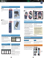
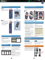
Trace back
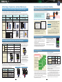
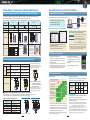
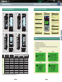
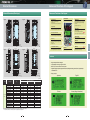
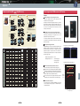
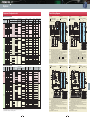
Loads sampling data retained in the inverter at an alarm to display with a graph.
Sampling time: 50μs to 1s (Note that sampling is enabled at 400μs or more except current.)
Sampling data are stored into the memory using the battery power. Data stored period: 5 years or more (at ambient temperature 25°C)
Battery: built-in as standard for 30kW or higher capacity models, available as option for 22kW or lower capacity models.
Self-diagnosis for detection circuit of the pulse encoder input signal (PA, PB)
Running efficiency of the unit can be improved by calculating the max. elevation speed achieved
by the weight for a vertical transfer unit or other similar units.
Display and
setting
Loader
Option: Use of OPC-VG1-TBSI
Multiple winding motor drive
Maximum number of motor windings: 6
Operation monitor (*1)
I/O monitor, system monitor, alarm history monitor
Control specification: Only vector control with a speed sensor is available.
Function code setting
Function code setting states can be checked. Also edit, transfer, comparison, initialization are available.
Option: Use of OPC-VG1-TBSI
Direct parallel connection system
Maximum number of parallel modules: 3
There are restrictions on the conditions of use, such as output wiring length. For details, refer to the User Manual.
Control
UP/DOWN control
Speed setting is possible by combining the UP command, DOWN command, and zero clear command using the external signal (DI signal).
Stopping function
3 types of stopping functions: STOP 1, 2 and 3.
PG pulse output
Outputs the input pulse such as a motor PG signal by fixed or free frequency dividing.
Open collector and complimentary (same voltage as PGP terminal) can be switched by setting the unit internal switch.
Observer
Suppresses load disturbances and vibrations.
Off-line tuning
Rotary type and non-rotary type are available for tuning the motor constants.
On-line tuning
Maintenance
Used for tuning continuosly motor constants due to the motor temperature change.
Communications
Compatibility with
earlier models
Standard function: position control by servo lock and built-in transmitting circuit.
Position control
Options: OPC-VG1-PG (PR) : for line driver type pulse command input
OPC-VG1-PGo (PR) : for open collector type pulse command input
Pulse train synchronous operation
Display
Display and
setting
Auto life judgment function installed
Common functions
• Displays and records accumulated time for control PCB capacitor life and cooling fan operation time
• Displays and records inverter operation time.
• Displays and records the maximum output current and the maximum internal temperature for the past one hour.
RS-485
This is a input terminal to connect computers and programmable controllers via RS-485 communications.
USB
USB connector (Mini B type) for connection with a computer.The following operations are enabled using the inverter
support loader: function code edit, transfer verification, inverter test run, and monitoring various states.
Function code data
Set the VG7 function codes to activate each operation of the code (excluding the function codes for the VG7 third motor).
Values read from the VG7 can be written to the FRENIC-VG without changing them by using the PC loader (except for some special items).
Communications
T-Link, SX bus, and CC-Link are fully compatible. The host PLC software can be used without any change (except for some special items).
VG7
Installation adaptor
An adapter to fit the installation dimensions of earlier models is available as option.
Standard function
Safe Torque Off (STO)
• Stops the inverter output transistor by hardware -and therefore stops the output torque of the motor- immediately
by turning OFF digital input signals (EN1 terminal or EN2 terminal), which are externally controlled.
Stopping function
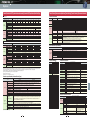
7-segment LED, LCD with backlight
Japanese, English, Chinese, Korean (French, Spanish, German, and Italian *1)
Running/stopping
Setting mode
Names and data are displayed.
Alarm mode
Displays the following alarm codes;
• dbH (Braking resistor overheat)(*)
• dCF (DC fuse blown)
• EF (Ground fault)
• Er1 (Memory error)
• Er2 (KEYPAD panel communication error)
• Er3 (CPU error)
• Er4 (Network error)
• Er5 (RS-485 error)
• Er6 (Operation procedure error) • Er7 (Output wiring error)
• Er8 (A/D converter error) • Er9 (Speed disagreement) • Erb (Inter-inverter communication error)
• Lin (Input phase loss)(*)
• LU (Undervoltage)
• nrb (NTC thermistor disconnection) • OC (Overcurrent)
• OH1 (Overheating at heat sink) • OH2 (External alarm input) • OH3 (Inverter internal overheat) • OH4 (Motor overheat)
• OL1 (Motor 1 overload)
• OL2 (Motor 2 overload)
• OL3 (Motor 3 overload)
• P9 (PG error)
• OU (Overvoltage)
• ErH(Hardware error)
• OLU (Inverter unit overload) • OS (Overspeed)
• dbA (Braking transistor abnormal) (*)
• PbF (Charging circuit error) (*) • dO (Excessive position deviation)
• EC(Encoder communications error) • Err (Simulated fault)
• OPL (Output phase loss detection) • dFA (DC fan lock)
• Et1(Encoder error)
• LOC (Start stall)
• ArF (Toggle error)
• ArE (E-SX error)
• Torque current reference value
• Output current
• Magnetic-flux calculation value
• PID output value
• Optional monitor 1 to 6
• Heat sink temperature
• Operation time
[L-AL] is displayed.
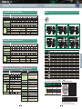
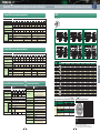
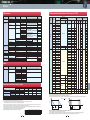
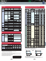
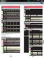
Product standard
Conformance to standard
Indoor use only. Free from corrosive and flammable gases, dusts, and oil mist (pollution degree 2 - IEC60664-1). No direct sunlight.
Ambient temperature
-10 to +50°C (-10 to +40°C: In case of 22 kW or lower
installed side-by-side without clearance)
Ambient humidity
5 to 95% RH (No dew condensation allowed)
Altitude
3000m or less
However, the output may be reduced at the altitude of 1001 to 3000m For use at the altitude of 2001 to 3000m,
the insulation class of the control circuit is changed from "Enhanced insulation" to "Basic insulation".
Vibration
• 200V 55kW or less, 400V 75kW or less
3mm: 2 to 9Hz or less, 9.8m/s2: 9 to 20Hz or less,
2m/s2: 20 to 55Hz or less, 1m/s2: 55 to 200Hz or less
• 200V 75kW or more, 400V 90kW or more
3mm: 2 to 9Hz or less, 2m/s2: 9 to 55Hz or less,
1m/s2: 55 to 200Hz or less
Storage temperature
-25 to 70°C (-10 to +30°C for long-term storage)
Storage humidity
5 to 95% RH (No dew condensation allowed)
Installation
environment
Stores and displays alarm date and time by the calendar and time display function [accuracy: ±27 sec/month (Ta=25°C)].
Data stored period: 5 years or more (at ambient temperature 25°C)
Battery: built-in as standard for 30kW or higher capacity models, available as option for 22kW or lower capacity models.
*1: This will be available soon.
*) Not available for the stack type
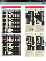
• US and Canada Safety Standard
UL, cUL (UL508C, C22.2 No.14) (Pending certification)
• Machinery Directive
IEC/EN ISO13849-1: PL-d (Pending certification)
IEC/EN60204-1: stop category 0 (Pending certification)
IEC/EN61800-5-2: SIL2 (Pending certification)
IEC/EN62061: SIL2 (Pending certification)
• Low Voltage Directive
EN61800-5-1: Over voltage category 3 (Pending certification)
• EMC Directive
IEC/EN 61800-3(Certification being approved),IEC/EN 61326-3-1(Pending certification)
(Emission) EMC filter (Option) : Unit type (220kW or lower) : Category 2
Unit type (280kW or higher) : Category 3
Stack type : Category 3
(Immunity) 2nd Env.
Usage environment
Stores and displays the detailed cause that triggers the minor fault.
The latest and last ten pieces of alarm codes and the latest and the last three pieces of alarm detailed data are stored.
Alarm during running
Main circuit capacitor life
OPC-VG1-PGo (PR) : for open collector type pulse command input
• Detected speed value
• Speed reference value
• Output frequency
• Torque reference value
• Torque calculation value • Power consumption (motor output)
• Output voltage
• DC link circuit voltage
• Magnetic-flux reference value
• Load shaft speed
• PID reference value
• PID feedback value
• Ai adjusted value (12)
• Ai adjusted value (Ai1)
• Ai adjusted value (Ai2)
• Presence of digital input/output signal
• Motor temperature
• Load factor
• Input power
• Integral power consumption
• Motor accumulated operation time/no. of starts (for each motor), etc.
Minor fault
Lit when the power is being supplied to the inverter body. Lit even with control power.
Options: OPC-VG1-PG (PR) : for line driver type pulse command input
Language display
Keypad
Safety function
Charge lamp
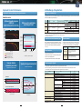
*1) This function is available by the licensed FRENIC VG Loader (WPS-VG1-PCL).
20
21
Terminal
Functions
Loads data from the inverter on a real-time basis to display with a graph.
Sampling time: 1ms to 1s
Protective
Functions
Real-time trace (*1)
External
Dimensions
Loads sampling data retained in the inverter to display with a graph.
Sampling time: 50μs to 1s
Names and
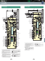
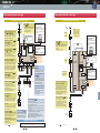
Functions of Parts
Historical trace (*1)
NTC thermistor (Fuji Electric product or equivalent item)
PTC thermistor (Trip level set by parameter) (for motor overheat protection)
Stack Type
External Dimensions Dedicated Motor
of Dedicated Motors Specifications
Load adaptive control function
Motor can be selected from three types by using (F79) or by combining the external signals (DI signals).
Unit Type
Wiring Diagram
PG detection circuit self diagnosis
Item
Options
Temperature detection
Stack Type
-10 to +40°C
0.3mm: 2 to 9Hz
1m/s2 : 9 to 200Hz
Warranty
Motor selection
Unit Type
Guidelines for
Delivery Period
Suppressing Harmonics
and Code
Item
Common
Standard
Specifications Specifications
Common items