1
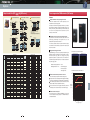
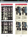
Our FRENIC series are the products specified in the "Guideline for Suppressing Harmonics by Customers Receiving High Voltage or Special High Voltage." When you enter
into a new contract with an electric power company or update a contract, you are requested by the electric power company to submit an accounting statement form.
D1
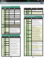
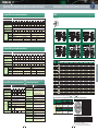
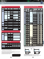
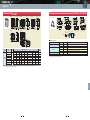
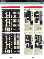
Dimensions [mm]
Fig
A
RHC7.5-2C
W
W1
H
H1
D
D1
n
B
C
250
226
380
358
245
125
2
10
10
Approx.
weight [kg]
12.5
RHC11-2C
RHC15-2C
H1
H
H1
H
340
240
480
460
255
145
2
10
10
24
RHC30-2C
B
340
240
550
530
255
145
2
10
10
29
RHC37-2C
B
375
275
615
595
270
145
2
10
10
36
RHC45-2C
RHC22-2C
C
C
B
RHC18.5-2C
200V
series
B
375
275
740
720
270
145
2
10
10
42
RHC55-2C
B
375
275
740
720
270
145
2
10
10
44
RHC75-2C
C
530
430
750
720
285
145
2
15
15
70
RHC90-2C
C
680
580
880
850
360
220
3
15
15
115
RHC7.5-4C
A
250
226
380
358
245
125
2
10
10
12.5
240
480
460
255
145
2
10
10
24
RHC11-4C
RHC15-4C
Fig. D
Fig. C
n- B
D
D1
W
D
D1
H
B
RHC30-4C
B
340
240
550
530
255
145
2
10
10
29
RHC37-4C
B
375
275
550
530
270
145
2
10
10
34
RHC45-4C
B
375
275
675
655
270
145
2
10
10
38
RHC55-4C
B
375
275
675
655
270
145
2
10
10
39
RHC75-4C
B
375
275
740
720
270
145
2
10
10
48
RHC90-4C
C
530
430
740
710
315
175
2
15
15
70
C
530
430
1000
970
360
220
2
15
15
100
C
680
580
1000
970
360
220
3
15
15
140
C
680
580
1400
1370
450
285
3
15
15
320
C
880
780
1400
1370
450
285
4
15
15
410
D
999
900
1550
1520
500
313.2
4
15
15
525
RHC22-4C
H1
H
n- B
H1
W
W1
340
RHC18.5-4C
400V
series
RHC110-4C
RHC132-4C
C
RHC160-4C
C
RHC200-4C
W1
RHC220-4C
RHC280-4C
RHC315-4C
RHC355-4C
RHC400-4C
RHC500-4C
RHC630-4C
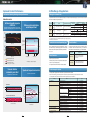
PWM converter main body (Stack Type)
Fig. B
11
11
1367.2
400V
70 75
191
70
55
56.2
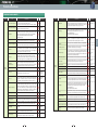
Fig
Body external [mm]
W
H
D
Approx.
weight [kg]
RHC132S-4D
A
226.2
1100
565
85
RHC160S-4D
A
226.2
1100
565
85
RHC200S-4D
A
226.2
1100
565
85
RHC220S-4D
B
226.2
1400
565
126
RHC280S-4D
B
226.2
1400
565
126
RHC315S-4D
B
226.2
1400
565
126
RHC220S-4D
Fig. B
RHC630B-4D
(*1)
–
–
–
–
–
RHC710B-4D
(*1)
–
–
–
–
–
RHC800B-4D
(*1)
–
–
–
–
–
Fig. C
Y1
Y1
Z1
X2
Y2
Z2
200V
series
H
H
X1
D1
D
6-terminal holes MAX. D2
(for screw M)
W
Z1
W1
4- K Elongated hole
Fig. D
D1
D
MAX. D2
X1
Y1
Z1
X2
Y2
Z2
400V
series
6-terminal holes
(for screw M)
H
X2
Y2
W1
Z2
4- K
11th
13th
17th
19th
23th
Over 25th
2.5
1.3
1.6
0.82
1.3
0.69
1.0
0.53
0.90
0.47
0.76
0.39
0.70
0.36
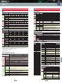
(1) "Inverter rated capacity" corresponding to "Pi"
• Calculate the input fundamental current l1 from the kW rating and efficiency of
the load motor, as well as the efficiency of the inverter. Then, calculate the
input rated capacity as shown below:
Input rated capacity = 3 x (power supply voltage) x I1 x 1.0228/1000[kVA]
Where 1.0228 is the 6-pulse converter's value obtained by (effective current) /
(fundamental current).
• When a general-purpose motor or inverter motor is used, the appropriate value shown in Table 2 can be
used. Select a value based on the kW rating of the motor used, irrespective of the inverter type.
D1
D
Terminal detail
D1
W1
W
4- K
D
50
3.7
5.5
7.5
11
15
Nominal applied motor [kW]
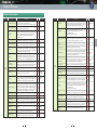
Dimensions [mm]
W
W1
H
D
D1
D2
K
M
A
180
75
205
105
85
95
7
M5
12
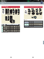
LR2-15C
B
195
75
215
131
110
130
7
M8
18
LR2-22C
C
240
80
340
215
180
145
10
M8
33
LR2-37C
C
285
95
420
240
205
150
12
M10
50
LR2-55C
C
285
95
420
250
215
160
12
M12
58
LR2-75C
C
330
110
440
255
220
165
12
M12
70
LR2-110C
C
345
115
500
280
245
185
12
M12
100
LR4-7.5C
B
180
75
205
105
85
90
7
M4
12
LR4-15C
A
195
75
215
131
110
120
7
M5
18
LR4-22C
C
240
80
340
215
180
120
10
M6
33
LR4-37C
C
285
95
405
240
205
130
12
M8
50
LR4-55C
C
285
95
415
250
215
145
12
M10
LR4-75C
C
330
110
440
255
220
150
12
M10
70
LR4-110C
C
345
115
490
280
245
170
12
M12
100
LR4-160C
C
380
125
550
300
260
185
15
M12
140
LR4-220C
C
450
150
620
330
290
230
15
M12
200
LR4-280C
C
480
160
740
330
290
240
15
M16
250
LR4-315C
C
480
160
760
340
300
250
15
M16
270
LR4-355C
C
480
160
830
355
315
255
15
M16
310
LR4-400C
C
480
160
890
380
330
260
19
M16
340
LR4-500C
C
525
175
960
410
360
290
19
M16
420
LR4-630C
D
600
200
640
440
390
290
19
4×M12
450
Fig
30
37
45
55
75
Pi 200V 34.7 42.8 52.1 63.7 87.2
[kVA] 400V 34.7 42.8 52.1 63.7 87.2
18.5
22
90
110 132 160 200 220
104
104
127
127
153
183
319
359
405
456
512
570
604
638
229
252
58
K31=3.4
K32=1.8
K33=1.8
K34=1.4
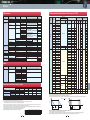
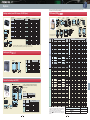
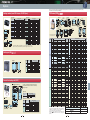
Table 5 Generated harmonic current [%], 3-phase rectifier (smoothing capacitor)
Degree
5th
7th
11th
13th
17th
19th
23th
25th
Without a reactor
With a reactor (ACR)
With a reactor (DCR)
With reactors (ACR and DCR)
65
38
30
28
41
14.5
13
9.1
8.5
7.4
8.4
7.2
7.7
3.4
5.0
4.1
4.3
3.2
4.7
3.2
3.1
1.9
3.2
2.4
2.6
1.7
3.0
1.6
1.8
1.3
2.2
1.4
• ACR: 3%
• DCR: Accumulated energy equal to 0.08 to 0.15ms (100% load conversion)
• Smoothing capacitor: Accumulated energy equal to 15 to 30ms (100% load conversion)
• Load: 100%
Generated nth harmonic current [%]
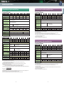
nth harmonic current [A] = Fundamental current [A] ×
100
Calculate the harmonic current of each order (harmonic number) using the following equation:
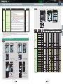
Table 6 Availability factors of inverters, etc. for building equipment (standard values)
Equipment type
718
Inverter capacity category
Single inverter availability factor
200kW or less
Over 200kW
———
———
50kW or less
200kVA
0.55
0.60
0.30
0.25
0.60
0.60
Air conditioning system
Sanitary pump
Elevator
Refrigerator, freezer
UPS (6-pulse)
[Correction coefficient according to contract demand level]
Conversion factor Ki Main applications
Without a reactor
With a reactor (ACR)
With a reactor (DCR)
With reactors (ACR and DCR)
Nominal applied motor [kW] 30
37
45
55
75
90 110 132 160 200 220
Input 200V 98.0 121 147 180 245 293 357
fundamental
current [A] 400V 49.0 60.4 73.5 89.9 123 147 179 216 258 323 355
6.6 kV converted value [mA] 2970 3660 4450 5450 7450 8910 10850 13090 15640 19580 21500
• For a load like elevators, which provides intermittent operation, or a load with a over-dimensioned motor
rating, reduce the current by multiplying the equation by the "maximum availability factor" of the load.
• The "maximum availability factor of an appliance" means the ratio of the capacity of the harmonic generator in operation at which the availability
reaches the maximum, to its total capacity, and the capacity of the generator in operation is an average for 30 minutes.
• In general, the maximum availability factor is calculated according to this definition, but the
standard values shown in Table 6 are recommended for inverters for building equipment.
• Depending on whether an optional ACR (AC REACTOR) or DCR (DC REACTOR) is used, apply the appropriate conversion
factor specified in the appendix to the guideline. The values of the converter factor are shown in Table 3.
3-phase rectifier
(smoothing capacitor)
22
61.4 73.1
30.7 36.6
1860 2220
(3) Maximum availability factor
(2) Values of "Ki (conversion factor)"
Circuit Type
18.5
(2) Calculation of harmonic current
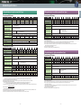
Although the equivalent capacity (Pi) is calculated using the equation of (input rated
capacity) x (conversion factor), catalog of conventional inverters do not contain input
rated capacities. A description of the input rated capacity is shown below:
2.2
Nominal applied motor [kW] 0.4 0.75 1.5 2.2 3.7 5.5 7.5 11
15
Input 200V 1.62 2.74 5.50 7.92 13.0 19.1 25.6 36.9 49.8
fundamental
current [A] 400V 0.81 1.37 2.75 3.96 6.50 9.55 12.8 18.5 24.9
6.6 kV converted value [mA] 49
83 167 240 394 579 776 1121 1509
Nominal applied motor [kW] 250 280 315 355 400 450 500 530 560 630
Input 200V
fundamental
current [A] 400V 403 450 506 571 643 723 804 852 900 1013
6.6 kV converted value [mA] 24400 27300 30700 34600 39000 43800 48700 51600 54500 61400
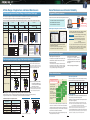
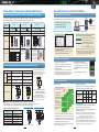
1. Calculation of Equivalent Capacity (Pi)
Circuit category
Approx.
weight [kg]
LR2-7.5C
H
X1
4- K Elongated hole
7th
3.5
1.8
Table 3 "Conversion factors Ki" for general-purpose inverters determined by reactors
to RHC315S-4D
Pressurization
reactor Type
6-terminal holes MAX. D2
(for screw M)
W
6-terminal holes MAX. D2
(for screw M)
W1
5th
6.6kV
22kV
3
Fig. A
X1 X2 Y1 Y2 Z1 Z2
Receiving voltage
Pi 200V
[kVA] 400V 286
<Boosting reactor>
W
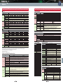
Table 1 Upper limits of harmonic outflow current per kW of contract demand [mA/kW]
Nominal applied motor [kW] 250 280 315 355 400 450 500 530 560 630
[Unit: mm]
455.3
to RHC200S-4D
Inverter Type
*1) Each stack corresponds to one phase, and one set of the inverter
consists of three stacks.
The touch panel is attached only to the V phase.
For external dimensions, contact Fuji Electric Sales Department.
14.5
RHC132S-4D
63 94
[Unit: mm]
455.3
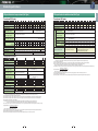
The level (calculated value) of the harmonic current that flows from the customer's receiving point
out to the system is subjected to the regulation. The regulation value is proportional to the
contract demand. The regulation values specified in the guideline are shown in Table 1.
Pi 200V 0.57 0.97 1.95 2.81 4.61 6.77 9.07 13.1 17.6 21.8 25.9
[kVA] 400V 0.57 0.97 1.95 2.81 4.61 6.77 9.07 13.1 17.6 21.8 25.9
3.2
91.2
834.6
1400(H)
1190
1027.8
70 75
191
70
55
14.5
3.2
91.2
1100(H)
956.5
789.7
56.2
(2) Regulation method
Nominal applied motor [kW] 0.4 0.75 1.5
MAX 565(D)
550
Series
63 94
Table 4 "Input fundamental currents" of general-purpose inverters determined by the nominal applied motors
In principle, the guideline applies to the customers that meet the following two conditions:
• The customer receives high voltage or special high voltage.
• The "equivalent capacity" of the converter load exceeds the standard value
for the receiving voltage (50kVA at a receiving voltage of 6.6kV).
Table 2 "Input rated capacities" of general-purpose inverters determined by the nominal applied motors
MAX 226.2(W)
220
144.8
30 160
1.6
Fig. A
MAX 565(D)
550
2.3
MAX 226.2(W)
220
144.8
30
160
(1) Scope of regulation
Protective
Functions
4- 18
Lifting hall
External
Dimensions
D1
PWM converter Type
D
n- B
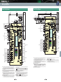
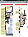
Names and
Functions of Parts
W
W1
D
External Dimensions Dedicated Motor
of Dedicated Motors Specifications
2- B
W
W1
Wiring Diagram
Fig. B
Fig. A
• General-purpose inverters
• Elevators
• Refrigerators,
air conditioning systems
• Other general appliances
2. Calculation of Harmonic Current
• Since the total availability factor decreases with increase in the building scale, calculating
reduced harmonics with the correction coefficient β defined in Table 7 below is permitted.
Table 7 Correction coefficient according to the building scale
Contract demand [kW] Correction coefficient β
300
500
1000
2000
1.00
0.90
0.85
0.80
*If the contract demand is between two
specified values shown in Table 7, calculate
the value by interpolation.
(4) Harmonic order to be calculated
(1) Value of "input fundamental current"
• Apply the appropriate value shown in Table 4 based on the kW rating of the
motor, irrespective of the inverter type or whether a reactor is used.
* If the input voltage is different, calculate the input fundamental current in
inverse proportion to the voltage.
51
Options
PWM converter main body (Unit Type)
Terminal
Functions
Application to "Guideline for Suppressing Harmonics by the Users Who Receive High Voltage or Special High Voltage"
Guidelines for
Suppressing Harmonics
External Dimensions
Common
Standard
Specifications Specifications
Guideline for Suppressing Harmonics
Calculate only the "5th and 7th" harmonic currents
Guidelines for
Suppressing Harmonics
Options