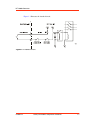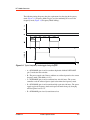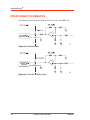
1
USER
MANUAL
HFV 8000
Generator
3 kW, 2 MHz, 208 V Input
5705072-F
November 2002
Advanced Energy Industries, Inc.
1625 Sharp Point Drive
Fort Collins, CO 80525 USA
800.446.9167
[email protected]
®
User Manual
HFV 8000 Generator
5705072-F
Advanced Energy®
COPYRIGHT
This manual and the information contained herein is the proprietary property of
Advanced Energy Industries, Inc.
No part of this manual may be reproduced or copied without the express written
permission of Advanced Energy Industries, Inc. Any unauthorized use of this manual
or its contents is strictly prohibited. Copyright © 1997-2002 Advanced Energy
Industries, Inc. All Rights Reserved.
DISCLAIMER AND LIMITATION OF LIABILITY
The information contained in this manual is subject to change by Advanced Energy
Industries, Inc. without prior notice. Advanced Energy Industries, Inc. makes no
warranty of any kind whatsoever, either expressed or implied, with respect to the
information contained herein. Advanced Energy Industries, Inc. shall not be liable in
damages, of whatever kind, as a result of the reliance on or use of the information
contained herein.
PRODUCT USAGE STATEMENT
Read this entire manual and all other publications pertaining to the work to be
performed before you install, operate, or maintain this equipment. Practice all plant
and product safety instructions and precautions. Failure to follow instructions can
cause personal injury and/or property damage. If the equipment is used in a manner
not specified by the manufacturer, the protection provided by the equipment may be
impaired. All personnel who work with or who are exposed to this equipment must
take precautions to protect themselves against serious or possibly fatal bodily injury.
Advanced Energy Industries, Inc., (AE) provides information on its products and
associated hazards, but it assumes no responsibility for the after-sale operation of
the equipment or the safety practices of the owner or user. This equipment produces
or uses potentially lethal high-voltage, high-current, radio frequency (RF) energy.
NEVER DEFEAT INTERLOCKS OR GROUNDS.
ii
5705072-F
HFV 8000 Generator
TRADEMARKS
®
is a registered trademark of Advanced Energy Industries, Inc.
Advanced Energy® is a registered trademark of Advanced Energy Industries, Inc.
AE® is a registered trademark of Advanced Energy Industries, Inc.
SQS™ is a trademark of Tru-Connector Corporation, Peabody, MA.
CUSTOMER FEEDBACK
Advanced Energy’s technical writing staff has carefully developed this manual using
research-based document design principles. However, improvement is ongoing, and
the writing staff welcomes and appreciates customer feedback. Please send any
comments on the content, organization, or format of this user manual to:
• [email protected]
To order a manual, please contact Technical Support:
• [email protected]
5705072-F
iii
Advanced Energy®
iv
5705072-F
HFV 8000 Generator
Table of Contents
Chapter 1. Safety and Product Compliance Guidelines
Important Safety Information . . . . . . . . . . . . . . . . . . . . . . . . . . . . . . . . . . . . . . . . . 1-1
Interpreting the Manual . . . . . . . . . . . . . . . . . . . . . . . . . . . . . . . . . . . . . . . . . . . . . 1-1
Type Conventions . . . . . . . . . . . . . . . . . . . . . . . . . . . . . . . . . . . . . . . . . . . . . . 1-1
Danger, Warning, and Caution Boxes . . . . . . . . . . . . . . . . . . . . . . . . . . . . . . 1-2
Safety Guidelines . . . . . . . . . . . . . . . . . . . . . . . . . . . . . . . . . . . . . . . . . . . . . . . . . . 1-2
Rules for Safe Installation and Operation . . . . . . . . . . . . . . . . . . . . . . . . . . . . 1-2
Interpreting Product Labels . . . . . . . . . . . . . . . . . . . . . . . . . . . . . . . . . . . . . . . 1-3
Product Compliance . . . . . . . . . . . . . . . . . . . . . . . . . . . . . . . . . . . . . . . . . . . . . . . . 1-4
Product Certification . . . . . . . . . . . . . . . . . . . . . . . . . . . . . . . . . . . . . . . . . . . . 1-4
Safety and Compliance Directives and Standards . . . . . . . . . . . . . . . . . . . . . 1-4
Electromagnetic Compatibility (EMC) Directives and Standards . . . . . . . 1-5
Safety Directives and standards . . . . . . . . . . . . . . . . . . . . . . . . . . . . . . . 1-5
Industry Guidelines . . . . . . . . . . . . . . . . . . . . . . . . . . . . . . . . . . . . . . . . . 1-5
Conditions of Use . . . . . . . . . . . . . . . . . . . . . . . . . . . . . . . . . . . . . . . . . . . . . . 1-6
Interlocks . . . . . . . . . . . . . . . . . . . . . . . . . . . . . . . . . . . . . . . . . . . . . . . . . . . . . . . . 1-6
Chapter 2. Product Overview and Theory
General Description . . . . . . . . . . . . . . . . . . . . . . . . . . . . . . . . . . . . . . . . . . . . . . . . 2-1
Theory of Operation . . . . . . . . . . . . . . . . . . . . . . . . . . . . . . . . . . . . . . . . . . . . . . . . 2-2
Chapter 3. Product Specifications
Functional Specifications . . . . . . . . . . . . . . . . . . . . . . . . . . . . . . . . . . . . . . . . . . . . 3-1
Timing Diagrams . . . . . . . . . . . . . . . . . . . . . . . . . . . . . . . . . . . . . . . . . . . . . . . . . . 3-2
Physical Specifications . . . . . . . . . . . . . . . . . . . . . . . . . . . . . . . . . . . . . . . . . . . . . 3-5
Electrical Specifications . . . . . . . . . . . . . . . . . . . . . . . . . . . . . . . . . . . . . . . . . . . . . 3-6
Environmental Specifications . . . . . . . . . . . . . . . . . . . . . . . . . . . . . . . . . . . . . . . . . 3-8
Chapter 4. Communication Interfaces
Generator User Port (15-Pin) . . . . . . . . . . . . . . . . . . . . . . . . . . . . . . . . . . . . . . . . . 4-1
User Port Interface Cabling Requirements . . . . . . . . . . . . . . . . . . . . . . . . . . . 4-1
Generator User Port Pin Descriptions . . . . . . . . . . . . . . . . . . . . . . . . . . . . . . . 4-2
Interconnect Schematics . . . . . . . . . . . . . . . . . . . . . . . . . . . . . . . . . . . . . . . . . . . . 4-6
Serial I/O Host Port (RS-232 With AE Bus) . . . . . . . . . . . . . . . . . . . . . . . . . . . . . . 4-8
Host Connector and Pin Descriptions . . . . . . . . . . . . . . . . . . . . . . . . . . . . . . . 4-8
Host Port Settings . . . . . . . . . . . . . . . . . . . . . . . . . . . . . . . . . . . . . . . . . . . . . . 4-9
5705072-F
v
Advanced Energy®
AE Bus (Host) Port Transmission Parameters . . . . . . . . . . . . . . . . . . . . . . . 4-10
AE Bus Protocol . . . . . . . . . . . . . . . . . . . . . . . . . . . . . . . . . . . . . . . . . . . . . . 4-11
AE Bus Header Byte . . . . . . . . . . . . . . . . . . . . . . . . . . . . . . . . . . . . . . . 4-12
AE Bus Command Number Byte . . . . . . . . . . . . . . . . . . . . . . . . . . . . . . 4-12
AE Bus Optional Length Byte . . . . . . . . . . . . . . . . . . . . . . . . . . . . . . . . 4-13
AE Bus Data Bytes . . . . . . . . . . . . . . . . . . . . . . . . . . . . . . . . . . . . . . . . 4-13
AE Bus Checksum Byte . . . . . . . . . . . . . . . . . . . . . . . . . . . . . . . . . . . . . 4-13
Creating an Ideal Communications Transaction . . . . . . . . . . . . . . . . . . . . . . 4-14
T0: Host Transmits Message Packet . . . . . . . . . . . . . . . . . . . . . . . . . . . 4-14
T1: Unit Verifies Host Transmission Packet . . . . . . . . . . . . . . . . . . . . . 4-14
T2: Unit Transmits Response to Host . . . . . . . . . . . . . . . . . . . . . . . . . . 4-15
T3: Host Acknowledges Unit Response . . . . . . . . . . . . . . . . . . . . . . . . 4-15
AE Bus Communications Transaction Example . . . . . . . . . . . . . . . . . . 4-16
AE Bus Commands . . . . . . . . . . . . . . . . . . . . . . . . . . . . . . . . . . . . . . . . . . . 4-16
AE Bus Command Status Response (CSR) Codes . . . . . . . . . . . . . . . 4-16
AE Bus Command Set . . . . . . . . . . . . . . . . . . . . . . . . . . . . . . . . . . . . . . 4-17
Chapter 5. Installation, Setup, and Operation
Preparing to Install the HFV generator . . . . . . . . . . . . . . . . . . . . . . . . . . . . . . . . . 5-1
Spacing Requirements . . . . . . . . . . . . . . . . . . . . . . . . . . . . . . . . . . . . . . . . . . 5-1
Installation Requirements . . . . . . . . . . . . . . . . . . . . . . . . . . . . . . . . . . . . . . . . 5-1
Unpacking . . . . . . . . . . . . . . . . . . . . . . . . . . . . . . . . . . . . . . . . . . . . . . . . . . . . 5-2
Installing the HFV generator . . . . . . . . . . . . . . . . . . . . . . . . . . . . . . . . . . . . . . . . . 5-2
Front Panel Drawing . . . . . . . . . . . . . . . . . . . . . . . . . . . . . . . . . . . . . . . . . . . . 5-3
Rear Panel Drawing . . . . . . . . . . . . . . . . . . . . . . . . . . . . . . . . . . . . . . . . . . . . 5-4
Electromagnetic Field (EMF) Shielding Requirements . . . . . . . . . . . . . . . . . . 5-5
Grounding . . . . . . . . . . . . . . . . . . . . . . . . . . . . . . . . . . . . . . . . . . . . . . . . . . . . 5-5
Connecting Cooling Water . . . . . . . . . . . . . . . . . . . . . . . . . . . . . . . . . . . . . . . 5-5
Connecting I/O and Auxiliary Connectors . . . . . . . . . . . . . . . . . . . . . . . . . . . . 5-7
Connecting Output Power . . . . . . . . . . . . . . . . . . . . . . . . . . . . . . . . . . . . . . . . 5-7
Connecting Input Power . . . . . . . . . . . . . . . . . . . . . . . . . . . . . . . . . . . . . . . . . 5-8
First-Time Operation . . . . . . . . . . . . . . . . . . . . . . . . . . . . . . . . . . . . . . . . . . . . . . . 5-9
Before Engaging the Rear Circuit Breaker . . . . . . . . . . . . . . . . . . . . . . . . . . . 5-9
Before Enabling the Output . . . . . . . . . . . . . . . . . . . . . . . . . . . . . . . . . . . . . . 5-9
Enabling the Output . . . . . . . . . . . . . . . . . . . . . . . . . . . . . . . . . . . . . . . . . . . 5-10
Meeting Minimum Power Threshold . . . . . . . . . . . . . . . . . . . . . . . . . . . . . . . 5-11
Normal Operation . . . . . . . . . . . . . . . . . . . . . . . . . . . . . . . . . . . . . . . . . . . . . . . . 5-11
Regulation Mode . . . . . . . . . . . . . . . . . . . . . . . . . . . . . . . . . . . . . . . . . . . . . . 5-11
Center Frequency Mode . . . . . . . . . . . . . . . . . . . . . . . . . . . . . . . . . . . . . . . . 5-11
Selecting Center Frequency Mode . . . . . . . . . . . . . . . . . . . . . . . . . . . . 5-12
Automatic Tuning Mode . . . . . . . . . . . . . . . . . . . . . . . . . . . . . . . . . . . . . . . . 5-12
Selecting Automatic Tuning Mode . . . . . . . . . . . . . . . . . . . . . . . . . . . . . 5-12
Adjusting Tuning Parameters . . . . . . . . . . . . . . . . . . . . . . . . . . . . . . . . 5-13
Display Mode and the LCD Display Indicator . . . . . . . . . . . . . . . . . . . . . . . . 5-15
Monitoring the Generator . . . . . . . . . . . . . . . . . . . . . . . . . . . . . . . . . . . . . . . . . . . 5-16
Running Internal Diagnostics . . . . . . . . . . . . . . . . . . . . . . . . . . . . . . . . . . . . . . . . 5-17
vi
5705072-F
HFV 8000 Generator
Chapter 6. Troubleshooting and Global Customer
Support
Before Calling AE Global Customer Support . . . . . . . . . . . . . . . . . . . . . . . . . . . . . 6-1
Troubleshooting Guide . . . . . . . . . . . . . . . . . . . . . . . . . . . . . . . . . . . . . . . . . . 6-1
Error Indications . . . . . . . . . . . . . . . . . . . . . . . . . . . . . . . . . . . . . . . . . . . . . . . . . . . 6-2
Front Panel Display (LCD) Not Lit . . . . . . . . . . . . . . . . . . . . . . . . . . . . . . . . . . 6-2
Advanced Energy Displayed on LCD . . . . . . . . . . . . . . . . . . . . . . . . . . . . . . . 6-2
Fault Indicator On . . . . . . . . . . . . . . . . . . . . . . . . . . . . . . . . . . . . . . . . . . . . . . 6-2
Overtemperature Fault . . . . . . . . . . . . . . . . . . . . . . . . . . . . . . . . . . . . . . . 6-3
RF Enable Without Interlock Fault . . . . . . . . . . . . . . . . . . . . . . . . . . . . . . 6-3
Input Line Fault . . . . . . . . . . . . . . . . . . . . . . . . . . . . . . . . . . . . . . . . . . . . 6-3
Interlock OK Indicator Off . . . . . . . . . . . . . . . . . . . . . . . . . . . . . . . . . . . . . . . . 6-3
What is the Interlock? . . . . . . . . . . . . . . . . . . . . . . . . . . . . . . . . . . . . . . . 6-4
Load Regulation Indicator Flashing . . . . . . . . . . . . . . . . . . . . . . . . . . . . . . . . 6-4
RF On Indicator Off . . . . . . . . . . . . . . . . . . . . . . . . . . . . . . . . . . . . . . . . . . . . . 6-5
At Set Point Indicator Off . . . . . . . . . . . . . . . . . . . . . . . . . . . . . . . . . . . . . . . . 6-5
Internal Fault Check . . . . . . . . . . . . . . . . . . . . . . . . . . . . . . . . . . . . . . . . . 6-6
External Load Checks - Open/Short RF Output Path . . . . . . . . . . . . . . . 6-6
No Output / No Plasma . . . . . . . . . . . . . . . . . . . . . . . . . . . . . . . . . . . . . . . . . . 6-7
High Reflected Power . . . . . . . . . . . . . . . . . . . . . . . . . . . . . . . . . . . . . . . . . . . 6-7
AE World Wide Web Site . . . . . . . . . . . . . . . . . . . . . . . . . . . . . . . . . . . . . . . . . . . . 6-8
AE Global Customer Support . . . . . . . . . . . . . . . . . . . . . . . . . . . . . . . . . . . . . . . . . 6-8
Returning Units for Repair . . . . . . . . . . . . . . . . . . . . . . . . . . . . . . . . . . . . . . . . . . . 6-9
Warranty . . . . . . . . . . . . . . . . . . . . . . . . . . . . . . . . . . . . . . . . . . . . . . . . . . . . . . . 6-10
Authorized Returns . . . . . . . . . . . . . . . . . . . . . . . . . . . . . . . . . . . . . . . . . . . . 6-10
Warranty Statement . . . . . . . . . . . . . . . . . . . . . . . . . . . . . . . . . . . . . . . . . . . 6-10
5705072-F
vii
Advanced Energy®
viii
5705072-F
HFV 8000 Generator
List of Tables
Electromagnetic compatibility (EMC) directives and standards . . . . . . . . . . . . . . . . . . 1-5
Safety directives and standards . . . . . . . . . . . . . . . . . . . . . . . . . . . . . . . . . . . . . . . . . . 1-5
Industry guidelines . . . . . . . . . . . . . . . . . . . . . . . . . . . . . . . . . . . . . . . . . . . . . . . . . . . . 1-5
Hardware interlocks . . . . . . . . . . . . . . . . . . . . . . . . . . . . . . . . . . . . . . . . . . . . . . . . . . . 1-6
HFV generator theory of operation . . . . . . . . . . . . . . . . . . . . . . . . . . . . . . . . . . . . . . . . 2-2
Functional specifications . . . . . . . . . . . . . . . . . . . . . . . . . . . . . . . . . . . . . . . . . . . . . . . . 3-1
Physical specifications . . . . . . . . . . . . . . . . . . . . . . . . . . . . . . . . . . . . . . . . . . . . . . . . . 3-6
Electrical specifications . . . . . . . . . . . . . . . . . . . . . . . . . . . . . . . . . . . . . . . . . . . . . . . . . 3-6
Climatic specifications . . . . . . . . . . . . . . . . . . . . . . . . . . . . . . . . . . . . . . . . . . . . . . . . . . 3-8
Environmental specifications . . . . . . . . . . . . . . . . . . . . . . . . . . . . . . . . . . . . . . . . . . . . . 3-8
Generator User port pin descriptions . . . . . . . . . . . . . . . . . . . . . . . . . . . . . . . . . . . . . . 4-2
Host port connector . . . . . . . . . . . . . . . . . . . . . . . . . . . . . . . . . . . . . . . . . . . . . . . . . . . . 4-9
Host port settings . . . . . . . . . . . . . . . . . . . . . . . . . . . . . . . . . . . . . . . . . . . . . . . . . . . . 4-10
Baud rate for Host port . . . . . . . . . . . . . . . . . . . . . . . . . . . . . . . . . . . . . . . . . . . . . . . . 4-10
Transmission parameters . . . . . . . . . . . . . . . . . . . . . . . . . . . . . . . . . . . . . . . . . . . . . . 4-11
Command Status Response (CSR) codes . . . . . . . . . . . . . . . . . . . . . . . . . . . . . . . . . 4-16
Host port commands . . . . . . . . . . . . . . . . . . . . . . . . . . . . . . . . . . . . . . . . . . . . . . . . . . 4-18
Indicators . . . . . . . . . . . . . . . . . . . . . . . . . . . . . . . . . . . . . . . . . . . . . . . . . . . . . . . . . . . 5-16
Global Customer Support locations . . . . . . . . . . . . . . . . . . . . . . . . . . . . . . . . . . . . . . . 6-8
5705072-F
ix
Advanced Energy®
x
5705072-F
HFV 8000 Generator
List of Figures
Interlock circuit . . . . . . . . . . . . . . . . . . . . . . . . . . . . . . . . . . . . . . . . . . . . . . . . . . . . . . . 1-7
HFV generator block diagram . . . . . . . . . . . . . . . . . . . . . . . . . . . . . . . . . . . . . . . . . . . . 2-2
Typical frequency mode toggle timing diagram . . . . . . . . . . . . . . . . . . . . . . . . . . . . . . . 3-3
Typical mode polling timing diagram . . . . . . . . . . . . . . . . . . . . . . . . . . . . . . . . . . . . . . . 3-4
Mounting dimensions (shown without optional water solenoid) . . . . . . . . . . . . . . . . . . 3-6
Generator User port connector . . . . . . . . . . . . . . . . . . . . . . . . . . . . . . . . . . . . . . . . . . . 4-1
Reflected power . . . . . . . . . . . . . . . . . . . . . . . . . . . . . . . . . . . . . . . . . . . . . . . . . . . . . . 4-6
Forward/load power output . . . . . . . . . . . . . . . . . . . . . . . . . . . . . . . . . . . . . . . . . . . . . . 4-6
RF power enable . . . . . . . . . . . . . . . . . . . . . . . . . . . . . . . . . . . . . . . . . . . . . . . . . . . . . . 4-7
Forward/load power set point . . . . . . . . . . . . . . . . . . . . . . . . . . . . . . . . . . . . . . . . . . . . 4-7
RF power on status . . . . . . . . . . . . . . . . . . . . . . . . . . . . . . . . . . . . . . . . . . . . . . . . . . . . 4-8
Interlock loop . . . . . . . . . . . . . . . . . . . . . . . . . . . . . . . . . . . . . . . . . . . . . . . . . . . . . . . . . 4-8
Serial AE Bus Host port connector . . . . . . . . . . . . . . . . . . . . . . . . . . . . . . . . . . . . . . . . 4-9
Graphic representation of a message packet . . . . . . . . . . . . . . . . . . . . . . . . . . . . . . . 4-12
AE Bus communications transaction . . . . . . . . . . . . . . . . . . . . . . . . . . . . . . . . . . . . . . 4-14
Communications transaction example . . . . . . . . . . . . . . . . . . . . . . . . . . . . . . . . . . . . 4-16
Front view . . . . . . . . . . . . . . . . . . . . . . . . . . . . . . . . . . . . . . . . . . . . . . . . . . . . . . . . . . . 5-3
Rear view (shown without optional water solenoid) . . . . . . . . . . . . . . . . . . . . . . . . . . . 5-4
5705072-F
xi
Advanced Energy®
xii
5705072-F
HFV 8000 Generator
Chapter
1
Safety and Product Compliance
Guidelines
IMPORTANT SAFETY INFORMATION
To ensure safe installation and operation of the Advanced Energy® HFV generator,
read and understand this manual before attempting to install and operate this unit. At a
minimum, read and follow the safety instructions and practices documented under
“Safety Guidelines” on page 1-2.
INTERPRETING THE MANUAL
The following sections explain the document type conventions and the danger,
warning, and caution boxes that provide information about the specific levels of
hazard seriousness.
Type Conventions
Please note the following type conventions:
• Pin (2) and signal names (REFLECTED POWER OUTPUT) appear in capitalized
italics.
• Technical terms appear in italicized text when first introduced, and many terms
are defined in the Glossary.
• Unit labels (switches, indicators, and so forth) generally appear in boldface letters
as they are labeled on the unit (Standby).
• Commands (5) and command names (starting frequency) appear in boldface
lowercase letters.
5705072-F
Safety and Product Compliance Guidelines
1-1
Advanced Energy®
Danger, Warning, and Caution Boxes
This symbol represents important notes concerning potential harm to people, this unit,
or associated equipment. Advanced Energy® includes this symbol in Danger,
Warning, and Caution boxes to identify specific levels of hazard seriousness.
DANGER indicates an imminently hazardous situation that, if not
avoided, will result in death or serious injury. DANGER is limited to the
most extreme situations.
WARNING indicates a potentially hazardous situation that, if not avoided,
could result in death or serious injury, and/or property damage.
CAUTION indicates a potentially hazardous situation that, if not avoided,
could result in minor or moderate injury, and/or damage to property.
CAUTION is also used for property-damage-only accidents.
SAFETY GUIDELINES
Review the following information before attempting to install and operate the product.
Rules for Safe Installation and Operation
Please note the following rules for safe installation and operation of the product.
• Do not attempt to install or operate this equipment without proper training.
• Ensure that this unit is properly grounded.
• Ensure that all cables are properly connected.
• Verify that input line voltage and current capacity are within specifications before
turning on the power supplies.
• Use proper electrostatic discharge (ESD) precautions.
• Always be careful around this equipment.
1-2
Safety and Product Compliance Guidelines
5705072-F
HFV 8000 Generator
Interpreting Product Labels
The following labels could appear on your unit.
Hazardous voltage
Short circuit protected
High voltage
Protective Earth ground
Earth ground
CE label
Nonionizing radiation
5705072-F
Safety and Product Compliance Guidelines
1-3
Advanced Energy®
Hot surface
Warning (refer to manual)
NRTL
PRODUCT COMPLIANCE
The following sections include information about unit compliance and certification,
including the conditions of use required to be in compliance with the standards and
directives.
Product Certification
Certain options of this product are certified by:
• Canadian Standards Association (CSA) (NRTL/C)
• CE marking, self addressed by AE Compliance Engineering
• EMC measurements, verified by TÜV
For more information, refer to the letter of conformance (US) or declaration of
conformity (EU) accompanying the product.
Safety and Compliance Directives and Standards
Certain options of this unit have been tested for and comply with the following
electromagnetic compatibility (EMC) and safety directives and standards and industry
guidelines.
Note: This device must be installed and used only in compliance with the directives
and standards listed in addition to VDE 0113, EN 60204 (IEC 60204), and
applicable requirements.
1-4
Safety and Product Compliance Guidelines
5705072-F
HFV 8000 Generator
ELECTROMAGNETIC COMPATIBILITY (EMC) DIRECTIVES AND
STANDARDS
Table 1-1. Electromagnetic compatibility (EMC) directives and standards
Directive
Description
89/336/EEC
EC Council directive on the approximation of the laws of the
Member States relating to electromagnetic compatibility (EMC
Directive)
47 CFR Part 18
Code of Federal Regulations—Limits and methods of
measurement of radio interference characteristics of industrial,
scientific, and medical equipment
EN 55011
Limits and methods of measurement of radio disturbance
characteristics of industrial, scientific, medical (ISM) radio
frequency equipment (Class A, Group 2) (CISPR 11)
EN 61000-6-2
Electromagnetic Compatibility (generic immunity standard—
industrial)
SAFETY DIRECTIVES AND STANDARDS
Table 1-2. Safety directives and standards
Directive
Description
73/23/EEC
EC Council directive on the harmonization of the laws of the
Member States relating to electrical equipment designed for use
within certain voltage limits (LVD - Low Voltage Directive)
ANSI/ISA
82.02.01
Safety standard for electrical and electronic test, measuring,
controlling and related equipment—general requirements
(harmonized standard to IEC publication 61010-1)
CSA C22.2
No. 1010.1
Safety requirements for electrical equipment for measurement,
control, and laboratory use
EN 50178
Electronic equipment for use in electrical power installations
INDUSTRY GUIDELINES
Table 1-3. Industry guidelines
Guideline
Description
SEMI S2-0200
Environmental, health, and safety guidelines for semiconductor
manufacturing equipment
This device must be installed and used only in compliance with the standards listed in
addition to VDE 0113, EN 60204 (IEC 204), and applicable requirements.
5705072-F
Safety and Product Compliance Guidelines
1-5
Advanced Energy®
Conditions of Use
To comply with the stated directives and standards, you must meet the following
conditions of use:
• This device must be used in an overvoltage category II installation only.
• Before making any other connection, connect the auxiliary Protective Earth
ground conductor on the rear panel.
• Use only a shielded power cable on the output power connector.
• Install and operate this device only in a pollution degree 2 or better environment,
which means an indoor location such as a computer room, office, or factory floor
where only nonconductive pollution occurs during operation. Occasionally, a
temporary conductivity caused by condensation occurs when the device is not
operating.
• Nonstandard connectors for input/output power must be inaccessible to the user.
• Use only shielded cables on control, interface, and communication connectors.
INTERLOCKS
Advanced Energy Industries, Inc. products may include interlocks. When
interlocks exist, they are not intended for the protection of the operator,
but are intended to prevent damage to equipment or property. Hazardous
areas of Advanced Energy products are not operator accessible; the use
of a tool is required.
Table 1-4 lists the hardware interlocks associated with the HFV generator. To recover
from an interlock fault, see “Interlock OK Indicator Off” on page 6-3.
Note: For more information on satisfying the minimum operating requirements for
the HFV generator, see “Satisfying Minimal User Port Requirements for
Operation” on page 4-1.
Table 1-4. Hardware interlocks
Interlock Mechanism
Detection Method
Equipment Condition While
Interlock is Not Satisfied
RF output cover
Switch opens
The main contactor is open; RF
output is disabled
Front panel Standby
switch
Switch opens
The main contactor is open; RF
output is disabled
1-6
Safety and Product Compliance Guidelines
5705072-F
HFV 8000 Generator
Figure 1-1 illustrates the interlock circuit.
Figure 1-1. Interlock circuit
5705072-F
Safety and Product Compliance Guidelines
1-7
Advanced Energy®
1-8
Safety and Product Compliance Guidelines
5705072-F
HFV 8000 Generator
Chapter
2
Product Overview and Theory
GENERAL DESCRIPTION
This HFV generator is a 3-kilowatt, high-efficiency, 1.765-megahertz to 2.165megahertz generator intended for continuous, heavy use in a vacuum chamber
environment. The generator employs Advanced Energy’s patented RF circuit
topology in a compact, rack-mountable enclosure.
Designed to regulate on forward power or load (delivered) power into a broad range of
output impedances, the HFV generator can operate in center frequency mode or in
automatic tuning mode. Direct digital synthesis (DDS) continually adjusts the
operating frequency in order to minimize the reflected power for a given load
impedance. Both center frequency and automatic tuning modes support operation into
a fixed impedance matching network, which simplifies system complexity, increases
reliability, and improves process-to-process repeatability. Automatic tuning mode
continuously minimizes the mismatch to the generator. This mode is only available
while in forward power regulation mode. In load power regulation, an initial
frequency sweep is performed to determine the frequency that yields the minimum
reflected power. For operation instructions, see “First-Time Operation” on page 5-9
and “Normal Operation” on page 5-11.
You can control the HFV generator through a 15-pin, custom analog Generator User
port (see “Generator User Port (15-Pin)” on page 4-1). You can also control the
frequency and frequency tuning algorithm through the generator’s serial Host port,
which is RS-232, RS-422, and RS-485 compatible (see “Serial I/O Host Port (RS-232
With AE Bus)” on page 4-8).
In addition, Advanced Energy has Virtual Front Panel (VFP) software available for
purchase. With VFP software, you can control most generator functions and monitor
the HFV generator using a personal computer. To order VFP software, contact your
AE sales representative (for contact information, see Table 6-1 on page 6-8).
The front panel features a liquid crystal display (LCD) mode selector and five status
indicators. The HFV generator also has an internal diagnostics program to help
determine generator integrity. The front panel is primarily for monitoring the
operation of the generator or initiating the internal diagnostics program (see “Front
view” on page 5-3).
The HFV generator is designed to fit into a 48-centimeter (19″ ) rack with a panel
height of 13 centimeters (5.25″ ) (3U). The generator operates from a 208 VAC, 3 φ,
50/60 Hz power source and can tolerate arbitrary phase rotation of the input power
connections. The HFV generator is water-cooled with all power, interface-port, and
water connections at the rear of the generator (see Figure 5-2 on page 5-4).
5705072-F
Product Overview and Theory
2-1
Advanced Energy®
THEORY OF OPERATION
Figure 2-1 represents high-level modules of HFV generator operation; Table 2-1
explains each module.
Front Panel Switch
Generator User Cable
DeviceNet Interface
AC Line In
Logic Control &
Low Voltage
Conversion
(2)
Line Input
Section
(1)
RF Power
Conversion
(4)
DC Power
Conversion
(3)
Water In
Water Out
RF Out
(Use RG-393 or
equivalent cable)
Water Solenoid
(optional)
(5)
Figure 2-1. HFV generator block diagram
Table 2-1. HFV generator theory of operation
Module
Explanation
(1) Line input section
The line input section provides input line filtering and
circuit protection.
(2) Logic control and low
voltage conversion
This module controls the operation of HFV generator power
conversions.
(3) DC power conversion
The DC power conversion module converts AC line power
to regulated DC power.
(4) RF power conversion
The RF power conversion module converts DC power to
regulated RF power.
(5) Water solenoid
(optional)
The optional water solenoid provides water flow control. If
your generator has this option, the valve controlling water
flow opens during RF power delivery and closes 30 minutes
after the last RF off command.
2-2
Product Overview and Theory
5705072-F
HFV 8000 Generator
Chapter
3
Product Specifications
FUNCTIONAL SPECIFICATIONS
Table 3-1 describes the functional specifications of the HFV generator.
Table 3-1. Functional specifications
Description
Specification
Output regulation modes
The HFV generator provides forward power and load
(delivered) power regulation modes, as measured at the
RF output.
To set, see:
• Command 12 in Table 4-7 on page 4-18
• “Regulation Mode” on page 5-11
• “Timing Diagrams” on page 3-2
Interface configurations
The HFV generator has a 15-pin analog Generator User
port for generator control. A 9-pin serial Host port (RS232, RS-422, and RS-485 compatible) is available for
pre-selecting the frequency or frequency tuning
algorithm. You can access the 9-pin Host port through a
rear panel access cover (see “Host Connector and Pin
Descriptions” on page 4-8 and Figure 5-2 on page 5-4).
Host port control features
The Host port controls the frequency and frequency
tuning algorithm, along with other control features (see
“AE Bus Command Set” on page 4-17).
5705072-F
Product Specifications
3-1
Advanced Energy®
Table 3-1. Functional specifications (Continued)
Description
Specification
RF output operating conditions
To achieve RF output, ensure the following conditions
are met:
• External interlock loop closed (less than 15 Ω in
series path)
• RF output cover firmly attached
• Front panel Standby switch in the Standby (up)
position
• No faults present (Front Panel Fault indicator
should be off)
• No chamber arcing present
• Set point signal > 220 mV (Generator User port)
• RF Enable command present
Cooling
The HFV generator is water-cooled to allow operation in
a clean room environment. The HFV generator will not
reduce performance when the inlet water temperature is
+15°C to +30°C (59°F to 86°F) and the flow rate is
11.4 lpm (3 gpm) or greater. All supplied water
connections should be 9.53 mm (3/8″ ) ID or larger
water lines. Keep the incoming and outgoing water lines
as short as possible and the outlet back-pressure
minimized.
In addition, you may purchase an optional water
solenoid to control water flow. A valve automatically
opens during RF power delivery and closes 30 minutes
after the last RF off command. An electrical connector is
located on the rear panel for this option. To order the
optional solenoid, contact AE Global Customer Support
(see “AE Global Customer Support” on page 6-8).
TIMING DIAGRAMS
Operators can switch between center frequency mode and automatic tuning mode
either manually or through the generator Generator User port (see also “Center
Frequency Mode” on page 5-11 and “Automatic Tuning Mode” on page 5-12). Center
frequency mode, indicated on the front panel by a blinking LOAD REG indicator,
limits the generator output frequency to 1.965 MHz and is typically used for system
calibration. Automatic tuning mode is the common mode of use that allows the
operator to determine the output frequency range. To set the output frequency range
through the Host port, see commands 3, 4, and 5 in Table 4-7 on page 4-18.
3-2
Product Specifications
5705072-F
HFV 8000 Generator
The following timing diagrams show the requirements for changing the frequency
mode (Figure 3-1, Frequency Mode Toggle,) and for confirming the status of the
frequency mode (Figure 3-2,Frequency Mode Polling).
Figure 3-1. Typical frequency mode toggle timing diagram
• A—RF ENABLE (pins 4 and 9) transitions high with ANALOG SET POINT
(pin 5) inside the noise window.
• B—The power supply waits 50 msec and then sets reflected power level to current
frequency mode (Auto Mode = 10 V).
• C—RF ENABLE (pins 4 and 9) transitions low after 100 msec. The system
controller reads the reflected power signal to determine the frequency mode.
• D—RF ENABLE (pins 4 and 9) transitions high again after 200 msec. The power
supply toggles the frequency mode and reports the mode change by changing
reflected power level to 5 V.
• E—RF ENABLE (pins 4 and 9) transitions to low.
5705072-F
Product Specifications
3-3
Advanced Energy®
• F—The reflected power level holds at the new voltage until the original 500-msec
period elapses.
Figure 3-2. Typical mode polling timing diagram
• A—RF ENABLE (pins 4 and 9) transitions high with ANALOG SET POINT
(pin 5) inside the noise window.
• B—The power supply waits 50 msec and then sets the reflected power level to the
current frequency mode (Center Freq. Mode = 5 V).
• C—RF ENABLE (pins 4 and 9) transitions low after 100 msec. The system
controller reads the reflected power signal to determine the frequency mode.
• D—The reflected power level holds at the original voltage until the 500 msec
period elapses.
3-4
Product Specifications
5705072-F
HFV 8000 Generator
PHYSICAL SPECIFICATIONS
Figure 3-3 illustrates the HFV generator’s physical dimensions, and Table 3-2
describes the physical specifications.
5705072-F
Product Specifications
3-5
Advanced Energy®
Figure 3-3. Mounting dimensions (shown without optional water solenoid)
Table 3-2. Physical specifications
Description
Specification
Size
13.3 cm (H) x 43.2 cm (W) x 51.4 cm (D)
5.25″ (H) x 17.0″ (W) x 20.25″ (D).
Allow 10.16 cm (4.0″ ) additional depth for line cord
service loop (right-hand side of rear panel).
Allow 3.81 cm (1.50″ ) additional depth for the RF
output cover (left-hand side of rear panel).
Allow 11.94 cm (4.7″ ) additional depth for the
optional water solenoid.
See also Figure 3-3 on page 3-6.
Weight
34 kg (75 lb) maximum
Connector/cable specifications
RF output
SQS™ female connector
Note: RF output cable not provided; RG-393 or
equivalent recommended
AC input power
4-wire cord, 10 mm (8 AWG), 60 cm (2’) long (the
ground wire is an additional 55.8 cm [22"] longer).
Each conductor has #10 ring lugs installed
Generator User port
15-pin, shielded, female, subminiature-D
Host port
9-pin, shielded, female, subminiature-D
Coolant
3/8″ stainless steel, female NPT
ELECTRICAL SPECIFICATIONS
Table 3-3 describes the electrical specifications for the HFV generator.
Table 3-3. Electrical specifications
Description
Specification
Input power specifications
3-6
Line voltage
208 V, 3 φ with ground; no neutral connection required
Line frequency
50/60 Hz
Product Specifications
5705072-F
HFV 8000 Generator
Table 3-3. Electrical specifications (Continued)
Description
Specification
Line current
14 A at 176 VAC
12 A at 208 VAC
Power
4.5 kW maximum (at full rated RF output power)
Overcurrent protection
40 A circuit breaker
RF output specifications
Output power
Scaled for 3000 W maximum with operator-selectable
set point. RF is off when set point falls below 180 mV;
RF is on when set point rises above 220 mV (see Table
4-1 on page 4-2).
Reflected power
Reflected power is limited internally to 1000 W.
Regulation
Across full frequency range into 50 Ω load:
• Forward power regulation mode is ± 3.0% of
set point or ± 24 W (whichever is greater)
• Load power regulation mode is ± 4.0% of set point
or ± 32 W (whichever is greater)
• Display accuracy is ± 2% of set point (regulated)
or ± 16 W (whichever is greater)
Transient regulation
≤0.1% change for a 10% disturbance in the AC line
voltage
Frequency
1.765 to 2.165 MHz, center or automatic, selectable
through the 9-pin Host port or front panel LCD and
display mode switch (see “AE Bus Command Set” on
page 4-17 or “Display Mode and the LCD Display
Indicator” on page 5-15)
Response Time
≤100 ms rise (at full scale set point) and fall time from
RF On or RF Off
Load Impedance
50 Ω, ± 2 Ω center impedance
Harmonics
At full rated output, all harmonics are 21 dB below the
RF output signal when operated into a 50 Ω,
nonreactive load impedance. All spurious
(nonharmonic) outputs are 45 dB below the RF output
signal.
5705072-F
Product Specifications
3-7
Advanced Energy®
ENVIRONMENTAL SPECIFICATIONS
Table 3-4 and Table 3-5 describe the environmental specifications.
Table 3-4. Climatic specifications
Temperature
Operating
Storage
Transportation
Relative Humidity
Air Pressure
Class 3K3
Class 3K2
Class 3K3
5°C to +40°C
10% to 85% Note 1
80 kPa to 106 kPa
+41°F to +104°F
+2 g/m3 to +25 g/m3
800 mbar to 1060 mbar
(approximately 2000 m
above sea level)
Class 1K4
Class 1K3
Class 1K4
-25°C to +55°C
5% to 95%
80 kPa to 106 kPa
-13°F to +131°F
+1 g/m3 to +29 g/m3
800 mbar to 1060 mbar
(approximately 2000 m
above sea level)
Class 2K3
Class 2K3
Class 2K3
-25°C to +70°C
95%Note 2
70 kPa to 106 kPa
-13°F to +158°F
+60 g/m3 Note 3
700 mbar to 1060 mbar
(approximately 3265 m
above sea level)
Note 1 Noncondensing
Note 2
Maximum relative humidity when the unit temperature slowly increases, or when the unit
temperature directly increases from -25°C to +30°C
Note 3 Maximum absolute humidity when the unit temperature directly decreases from +70°C to
+15°C
Table 3-5. Environmental specifications
Description
Specification
Overvoltage
Category II
Pollution degree
2
Coolant requirements
3-8
Temperature
+15° C to +30° C (+59° F to +86° F) inlet temperature
Flow rate
11.4 lpm (3 gpm) minimum
Product Specifications
5705072-F
HFV 8000 Generator
Table 3-5. Environmental specifications (Continued)
Description
Pressure
Specification
517 kPa (75 psi) maximum inlet pressure
Note: If your generator has a water solenoid, the
maximum water pressure is 275 kPa (40 psi)
Contaminates
AE recommends the following specifications for the
water that cools the HFV generator:
• pH between 7 and 9
• Total chlorine < 20 ppm
• Total nitrate < 10 ppm
• Total sulfate < 100 ppm
• Total dissolved solids < 250 ppm
• Total hardness expressed as calcium carbonate
equivalent less than 250 ppm
• Specific resistivity of 2500 Ω per cm or higher at
25° C
• Total dissolved solids (TDS) as estimated by the
following:
TDS ≤
5705072-F
640,000
specific resistivity (Ω per cm)
Product Specifications
3-9
Advanced Energy®
3-10
Product Specifications
5705072-F
HFV 8000 Generator
Chapter
4
Communication Interfaces
GENERATOR USER PORT (15-PIN)
The 15-pin Generator User port on the HFV generator provides analog and digital
signals for controlling and monitoring the unit. This section describes the User port
connector, the minimal User port connections required to operate the unit, User port
cabling requirements, and detailed information about the User port signals.
The Generator User port is a 15-pin, shielded, female, subminiature-D connector
(see Figure 4-1).
Figure 4-1. Generator User port connector
User Port Interface Cabling Requirements
Connect the HFV generator’s User port to the system controller with a shielded, 15wire I/O cable. Shielded twisted-pair wiring may be used but is not mandatory.
Minimize signal losses by keeping the cable as short as possible. The maximum
recommended cable length between the HFV generator and the controller is 10 meters
(33 feet). Minimize interference from adjacent electrical equipment by terminating the
EMI shield in the cable to the metal shells of the cable’s connectors. Additionally, you
must tie the chassis of the HFV generator to a local earth ground through an
adequately sized copper grounding strap.
Note: Grounding the User port at the HFV generator reduces noise interference. To
avoid ground loop problems, you should typically ground only one end of the
User port cable.
5705072-F
Communication Interfaces
4-1
Advanced Energy®
Generator User Port Pin Descriptions
Table 4-1 describes the connector pins for the Generator User port interface.
Table 4-1. Generator User port pin descriptions
Signal
Pin
Return
Pin
Signal Name
2
6
REFLECTED
POWER OUTPUT
Analog
output
0 V to 10 V = 0 W to 1000 W
FORWARD/LOAD
POWER OUTPUT
Analog
output
0 V to 10 V = 0 W to 3000 W
3
6
Signal
Type
Description
(See Figure 4-2 on page 4-6 for an
electrical diagram.)
Forward power is represented
when forward power regulation is
selected. Load power is
represented when load power
regulation is selected.
To select regulation mode, see:
• Command 12 in Table 4-7 on
page 4-18
• “Regulation Mode” on
page 5-11
• “Timing Diagrams” on
page 3-2
(See Figure 4-3 on page 4-6 for an
electrical diagram.)
4-2
Communication Interfaces
5705072-F
HFV 8000 Generator
Table 4-1. Generator User port pin descriptions (Continued)
Signal
Pin
Return
Pin
4
9
Signal Name
RF POWER
ENABLE
Signal
Type
Input
Description
Enables RF output power with an
external contact closure between
pins 4 and 9. This pin is tied to
+15 V through a 1 kΩ resistor. In
order for the generator to deliver
RF output power, the conditions
below must be met in the
following order:
1. Interlocks satisfied
2. RF Power enabled and
Set point > 220 mV
3. Generator not in fault mode
(See Table 5-1 on page 5-16)
(See Figure 4-4 on page 4-7 for an
electrical diagram.)
5
6
FORWARD/LOAD
POWER SET
POINT
Analog
input
0 V to 10 V = 0 W to 3000 W
The set point circuitry uses
hysteresis. If RF on command
(pins 4 & 9) is enabled, the
set point signal must be greater
than 220 mV for RF to be turned
on, or less than 180 mV for it to
be turned off.
(See Figure 4-5 on page 4-7 for an
electrical diagram.)
6
5705072-F
RETURN
Common for pins 2, 3, and 5; tied
to chassis ground.
Communication Interfaces
4-3
Advanced Energy®
Table 4-1. Generator User port pin descriptions (Continued)
Signal
Pin
Return
Pin
7
8
Signal Name
RF POWER ON
STATUS
Signal
Type
Output
Description
Pin 7 is supplied with +15 V
through a 10 kΩ resistor. While
RF power is present at the output,
an internal relay opens the
contacts between pin 7 and pin 8.
(See Figure 4-6 on page 4-8 for an
electrical diagram.)
With pin 8 grounded externally,
pin 7 will be at +15 V when RF
power is present and at 0 V when
there is no RF power.
Note: For RF to be present at the
output, the output must be
enabled and the set point
level must be above the
minimum specification
(see “Electrical
specifications” on
page 3-6).
8
4-4
RF POWER ON
STATUS
REFERENCE
Output
Floating pin that can be used as a
reference for pin 7; while RF
power is present at the output, an
internal relay opens the contacts
between pin 7 and pin 8.
Communication Interfaces
5705072-F
HFV 8000 Generator
Table 4-1. Generator User port pin descriptions (Continued)
Signal
Pin
Return
Pin
9
Signal Name
RF POWER
ENABLE RETURN
Signal
Type
Output
Description
Enables output RF power with an
external contact closure between
pins 4 and 9; this pin is tied to the
LED anode of an opto-coupler
through a 1 kΩ resistor.
(See Figure 4-4 on page 4-7 for
an electrical diagram.)
11
12
INTERLOCK
LOOP
Enables the internal AC power
contactor with an external closure
between pins 11 and 12 (provided
front panel Standby switch is
closed and RF output cover is on).
External series resistance must be
15 Ω or less. This pin is tied to
+15 V by a resettable fuse.
Note: When this loop is
interrupted, the unit
disables the output by
opening the main contactor
inside the supply. Once the
interlock is reestablished,
the main contactor will
close, but the output will
not come on until the RF
POWER ENABLE line
(pin 4) is cycled.
(See Figure 4-7 on page 4-8 for an
electrical diagram.)
5705072-F
Communication Interfaces
4-5
Advanced Energy®
INTERCONNECT SCHEMATICS
The following electrical diagrams detail the interface circuitry in the HFV unit.
Figure 4-2. Reflected power
Figure 4-3. Forward/load power output
4-6
Communication Interfaces
5705072-F
HFV 8000 Generator
Figure 4-4. RF power enable
Figure 4-5. Forward/load power set point
5705072-F
Communication Interfaces
4-7
Advanced Energy®
Figure 4-6. RF power on status
Figure 4-7. Interlock loop
SERIAL I/O HOST PORT (RS-232 WITH AE BUS)
The HFV generator provides a serial communications interface through the AE Bus
Host port. The Host port enables you to modify the default settings of the complex
tuning algorithm for detailed process control and enhancement. For a complete list of
available functions, see “AE Bus Command Set” on page 4-17. To obtain sample AE
Bus host software, please contact AE Global Customer Support (see “AE Global
Customer Support” on page 6-8).
Note: The unit is configured at the factory to use RS-232 but may be changed to RS422 or RS-485 by contacting AE Technical Support (see “AE Global Customer
Support” on page 6-8).
Host Connector and Pin Descriptions
The serial AE Bus Host port is a 9-pin, female, shielded, subminiature-D connector.
To access the Host port:
1. Use a screwdriver to remove the two screws from the rear panel access cover (see
Figure 5-2 on page 5-4).
2. Remove the rear panel access cover. The Host port connector and an 8-position
DIP switch are directly behind the cover.
4-8
Communication Interfaces
5705072-F
HFV 8000 Generator
Figure 4-8 shows the serial Host port, and Table 4-2 describes each pin.
Figure 4-8. Serial AE Bus Host port connector
Table 4-2. Host port connector
Pin
Name
Description
1
RESERVED
Reserved for future use
2
TXD
RS-232 transmit data
3
RXD
RS-232 receive data
4
RESERVED
Reserved for future use
5
COM
Data common
6
TR−
RS-485 (−) xmit/rx data/RS-422 (−) rx data
7
TR+
RS-485 (+) xmit/rx data/RS-422 (+) rx data
8
RESERVED
Reserved for future use
9
RESERVED
Reserved for future use
Host Port Settings
An 8-position DIP switch determines the device ID (network address) and
communications baud rate.
To access the DIP switch:
1. Use a screwdriver to remove the two screws from the rear panel access cover (see
Figure 5-2 on page 5-4).
2. Remove the rear panel access cover. The Host port connector and an 8-position
DIP switch are directly behind the cover.
5705072-F
Communication Interfaces
4-9
Advanced Energy®
Up to 31 device addresses are available (address 0 is reserved for broadcast
commands). A switch in the OPEN or OFF position represents a binary 1 for address
selection purposes. Table 4-3 lists the switch designations, and Table 4-4 lists the
baud rate selections.
Table 4-3. Host port settings
Switch
1
Switch
2
Switch
3
Switch
4
Switch
5
Switch
6
Switch
7
A4
A3
A2
A1
A0
BR1
BR0
------
Host
Port
Address
LSB
Baud
Rate
Selection
MSB
Baud
Rate
Selection
LSB
Host
Port
Address
MSB
------
------
Switch
8
Open for RS232
Closed for RS485/422Note 1
Note 1 Requires
internal modification to the unit. Contact Global Customer Support before removing
the safety cover (see “AE Global Customer Support” on page 6-8).
Use A4 to A0 (straight binary representation) to select Host port addresses 1 to 31.
Use BR1 and BR0 to define baud rate selection (see also Table 4-4).
Table 4-4. Baud rate for Host port
BR1
BR0
Closed
Closed
1200
9600
Closed
Open
4800
19.2 K
Open
Closed
9600
38.4 K
Open
Open
19.2 K
57.6 K
Note 1
RS-232 (switch 8
open) Baud Rate
RS-485/422 (switch 8
closed) Baud RateNote 1
Requires internal modification to the unit. Contact Global Customer Support
before removing the safety cover (see “AE Global Customer Support” on
page 6-8).
AE Bus (Host) Port Transmission Parameters
The communications capability of the serial AE Bus Host port is limited to the
following parameters:
• Start bits: One
• Number of Data Bits: 8
• Parity: Odd
• Stop bits: One
4-10
Communication Interfaces
5705072-F
HFV 8000 Generator
• Low-order bytes transmitted before high-order bytes.
Table 4-5 lists the Host port transmission parameters.
Table 4-5. Transmission parameters
RS-232
RS-485
RS-422
Baud rate
(user
selectable)
1200, 4800, 9600,
19.2 K
9600, 19.2 K,
38.4 K, 57.6 K
9600, 19.2 K,
38.4 K, 57.6 K
Connector
pins
2, 3, 5
5, 6, 7
Internal jumper
The host computer must finish one transaction with the HFV generator before it
initiates another, either with the same unit or any other unit.
Note: The HFV generator sends data through pin 2 (TXD.D). This pin must be
connected to the receive pin (RXD.D) on the host computer’s PC serial
connector. The receive pin is normally pin 2 for a standard, 9-pin PC serial port
and normally pin 3 for a standard, 25-pin PC serial port.
AE Bus Protocol
The AE Bus protocol uses pure binary data (nothing is coded in ASCII) and is
designed to facilitate direct communications between a host computer and the HFV
generator.
The AE Bus message packet combines a set quantity of bits and bytes in such a way
that groups of information can be sent over communications lines at one time. Five
types of information (fields) make up communications message packets (see Figure 49):
• Header (address and the length of Data field)
• Command Number (the commands are listed in Table 4-7 on page 4-18)
• Optional Length byte
• Data
• Checksum
5705072-F
Communication Interfaces
4-11
Advanced Energy®
Figure 4-9 shows the organization of these fields in the AE Bus message packet. The
subsequent paragraphs describe each field in detail.
Figure 4-9. Graphic representation of a message packet
AE BUS HEADER BYTE
The first byte in each packet contains two pieces of information: five bits contain the
packet address, and three bits contain the data byte count. If the message packet
originates with the host computer (master), the address specifies the packet destination
(to an HFV generator, for example). If the packet is going to the host, the address
specifies the packet origin (from the HFV generator). The address section of the
Header field is five bits long (bits 3-7), which allows a total of 32 distinct addresses.
Address 0 (zero) is reserved for the network broadcast address; when this address is
used in a host-originated packet, all units execute the packet (but do not respond to the
host).
The remaining three bits (bits 0, 1, and 2) are the length bits. These bits tell the
receiving unit how long the Data field is so that the unit can determine when it has
received the entire message. If the Data field contains more than 6 bytes, the value of
these three bits will be set to 7 (07h), and the Optional length byte field will contain a
value indicating the number of data bytes in the Data field.
Note: The value of these bits refers only to the number of actual data bytes in the Data
field. Do not include the checksum byte when calculating the value for these
bits (see “AE Bus Checksum Byte” on page 4-13).
AE BUS COMMAND NUMBER BYTE
This one-byte field contains an 8-bit value from 0 to 255 (00h to ffh) representing the
command number. If the message packet originates with the host computer, this value
specifies the purpose of the message packet. If the message originates with the HFV
generator, the value specifies the command to which it is responding. See “AE Bus
Commands” on page 4-16 for a complete list of commands.
4-12
Communication Interfaces
5705072-F
HFV 8000 Generator
AE BUS OPTIONAL LENGTH BYTE
This field supplements the Header field and exists only when the length bits (bits 0, 1,
and 2) in the Header field contain a value of 7 (07h). If the number of data bytes in the
Data field is 6 or less, then the three length bits in the Header field are sufficient to
represent this amount 0 to 6 (00h to 06h). Since the Data field may contain up to 255
bytes of information, the Optional Length byte is required when the Data field is
larger than 6 bytes.
When the Data field is larger than 6 bytes, the length bits in the header (bits 0, 1, and
2) will equal 7 (07h) and the Optional Length byte will contain a one-byte value, from
7 to 255 (07h to ffh), representing the number of data bytes in the Data field.
AE BUS DATA BYTES
The Data field may contain from 0 to 255 bytes of binary data. This field contains
command-related data or a command status response (CSR). Since some commands
do not require data, sometimes the Data field is not present.
If the value specified in the length bits (bits 0, 1, and 2) of the Header field is 0 to 6,
the HFV generator expects 0 to 6 data bytes. However, if the value in the Header field
is 7 (07h), the HFV generator looks for the Optional Length byte after the Command
field and reads this value to calculate the data byte count.
AE BUS CHECKSUM BYTE
This one-byte field is the last byte in the packet. The value of this byte depends upon
the number of bytes in each of the preceding fields. The transmitting unit determines
this value by accumulating the exclusive-or (XOR) of all bytes of the packet up to, but
not including, the checksum value. The receiving unit accumulates the XOR of all
bytes of the packet, including the checksum. If the result is zero, the unit has received
the packet intact.
The unit will act on the message only if the address is valid and the checksum is
validated as having no parity errors.
5705072-F
Communication Interfaces
4-13
Advanced Energy®
Creating an Ideal Communications Transaction
Figure 4-10 illustrates the steps in an ideal communications transaction between a host
computer and the HFV generator.
Host
HFV generator
Figure 4-10. AE Bus communications transaction
T0: HOST TRANSMITS MESSAGE PACKET
The host computer sends a message packet to the HFV generator. The packet contains
one of the following:
• A command that requests data or status information
• A command and data that change a parameter setting
• An executable command
T1: UNIT VERIFIES HOST TRANSMISSION PACKET
Once the HFV generator receives the host computer transmission message packet, the
HFV generator verifies that the message is intended for it and not for another unit on
the network. At this time, the HFV generator also analyzes the checksum to verify that
the message was received correctly.
4-14
Communication Interfaces
5705072-F
HFV 8000 Generator
• If the address does not match, the HFV generator does not respond to the host
computer; the HFV generator resets and resumes waiting for a message addressed
to it. If the address matches but the exclusive-or (XOR) sum of the bytes in the
packet (including the checksum) is not zero, the HFV generator sends a negative
acknowledgment (NAK), hexadecimal 15h, to the host computer.
• If the address matches and the message is intact, the HFV generator sends an
acknowledgment (ACK), hexadecimal 06h, to the host computer.
If the HFV generator receives a request for data or status information, it gathers and
sends the requested information. Otherwise, it evaluates the incoming command and
sends a message packet that contains a one-byte data value (CSR code) to the host (see
“AE Bus Command Status Response (CSR) Codes” on page 4-16). CSR code 0 is sent
when the command has been accepted.
If the host receives a NAK (15h) from the HFV generator, the host either retransmits
the packet or does whatever else it has been programmed to do in this situation. If the
host receives an ACK (06h), it waits for the requested data or status information, or it
waits for the CSR code telling it whether or not the new parameter was accepted. If the
host receives no response within a reasonable period, it takes whatever action it has
been programmed to take.
T2: UNIT TRANSMITS RESPONSE TO HOST
The HFV generator prepares a response packet with the requested information or
appropriate CSR code, which it then transmits to the host computer. The host
computer then determines, by means of the checksum, if the response packet is
complete. If the host computer detects an error in the transmission (the checksum is
not validated), it can request the packet be sent again by transmitting a NAK (15h).
T3: HOST ACKNOWLEDGES UNIT RESPONSE
If the HFV generator receives an ACK (15h) from the host computer, it returns to the
normal waiting state. If the HFV generator receives a NAK (06h) from the host
computer, the HFV generator retransmits the response packet. The HFV generator
continues to retransmit in response to NAK transmissions until the host computer
stops the cycle. If the HFV generator receives no response, it assumes an ACK and
returns to the waiting state.
5705072-F
Communication Interfaces
4-15
Advanced Energy®
AE BUS COMMUNICATIONS TRANSACTION EXAMPLE
Figure 4-11 is a simplified graphic showing the steps in an example communications
transaction between a host computer and an HFV generator.
HFV generator
Host Computer
Figure 4-11. Communications transaction example
AE Bus Commands
The following sections describe the command status response (CSR) codes returned
by the HFV generator in response to a command as well as the AE Bus commands for
the HFV generator.
AE BUS COMMAND STATUS RESPONSE (CSR) CODES
When the HFV generator receives a command requesting a change in unit operation or
status (command numbers 1 through 127), it responds with a command status
response (CSR) code. The CSR is a single-byte number that indicates whether the unit
accepted or rejected the command and, in the case of rejection, the reason the unit
could not respond to the command. Use Table 4-6 to interpret the CSR codes.
Table 4-6. Command Status Response (CSR) codes
Value
0
Meaning
Command accepted
The following CSR codes are sent in response to a command that
was not accepted and indicate why the command was not
accepted.
1
4-16
Control mode is incorrect
Communication Interfaces
5705072-F
HFV 8000 Generator
Table 4-6. Command Status Response (CSR) codes (Continued)
Value
Meaning (Continued)
2
Output is on; change not allowed
3
Output is off; change not allowed
4
Data is out of range
5
Invalid parameter
7
Active fault(s) exist
8
Ramping is active; change not allowed
9
Data byte count is incorrect
16
Target life has been consumed
17
Output OFF timer active (minimum off time is 50 ms)
19
Recipe is active; change not allowed
21
Joule set point has not been reached
24
Bus fault active (high or low)
28
Set point exceeds user limit
30
TCC is active; change not allowed
36
Data sent is greater than user limit for P, V, or I
99
Command not accepted (there is no such command)
AE BUS COMMAND SET
The HFV generator AE Bus serial communication interface has two types of
commands:
• Commands 1 through 127 request a change to the HFV generator, such as turning
output on or off or changing a setting in the unit. The unit responds to these
commands by sending a command status response (CSR). This single-byte
response indicates whether the unit has accepted or rejected the command and, in
the case of rejection, the reason the unit could not respond to the command. For
more information on CSR codes, see “AE Bus Command Status Response (CSR)
Codes” on page 4-16.
• Command numbers 128 through 255 request information from the unit, such as
output on/off status and unit settings. The unit responds to these commands by
sending the data requested.
5705072-F
Communication Interfaces
4-17
Advanced Energy®
Table 4-7 lists the Host commands.
Table 4-7. Host port commands
Command
3
minimum
frequency
Description
Sets the minimum frequency.
Number of
Host Data
Bytes
Number of
Response
Data Bytes
4
1
CSR only
4
1
CSR only
Note: This command is invalid when the unit
is in center frequency mode.
Send four bytes, least significant byte first,
representing the minimum frequency value in
Hertz.
• Range is 1765000 to 2165000, but the
value cannot be greater than the value set
by command 4 (maximum frequency).
• For example, enter 2000000
(2,000,000 Hz).
Set maximum frequency with command 4.
Set starting frequency value with command 5.
Read back with command 133. See also
“Frequency Limits” on page 5-13.
4
maximum
frequency
Sets the maximum frequency. Send four
bytes, least significant byte first, representing
the maximum frequency value in Hertz.
Note: This command is invalid when the unit
is in center frequency mode.
• Range is 1765000 to 2165000, but the
value cannot be less than the value set by
command 3 (minimum frequency).
• For example, enter 2000000
(2,000,000 Hz).
Set minimum frequency with command 3.
Set starting frequency value with command 5.
Read back with command 134. See also
“Frequency Limits” on page 5-13.
4-18
Communication Interfaces
5705072-F
HFV 8000 Generator
Table 4-7. Host port commands (Continued)
Command
5
starting
frequency
Description
Sets the starting frequency. Send four bytes,
least significant byte first, representing the
starting frequency value in Hertz.
Number of
Host Data
Bytes
Number of
Response
Data Bytes
4
1
CSR only
1
1
CSR only
2
1
CSR only
1
1
CSR only
Note: This command is invalid when the unit
is in center frequency mode.
• The value must be greater than or equal
to the value set by command 3
(minimum frequency) and less than or
equal to the value set by command 4
(maximum frequency).
• For example, enter 2000000
(2,000,000 Hz).
Read back with command 135. See also
“Frequency Limits” on page 5-13.
7
reset tuning
parameters
Resets tuning parameters to factory defaults.
Send 1 byte to select the setting:
11
frequency
rate of
change
Specifies the frequency rate of change. Send
two bytes, least significant byte first,
representing the frequency rate of change in
seconds.
• 0 = Keep current settings
• 1 = Factory defaults
• Accepts a value of 5 to 1000 (0.005 s to
1.000 s, decimal is implied)
Read back with command 141. See also
“Frequency rate of change (ms)” on
page 5-13.
12
set
regulation
mode
Sets regulation mode. Send one data byte,
indicating the desired mode:
• 1 = Selected by external switch
• 2 = Forward power regulation
• 3 = Load (delivered) power regulation
Read back with command 132.
5705072-F
Communication Interfaces
4-19
Advanced Energy®
Table 4-7. Host port commands (Continued)
Command
14
tuning goal
Description
Specifies the desired goal that the tuning
algorithm will attempt to achieve. Send two
bytes, least significant byte first, representing
the desired goal.
Number of
Host Data
Bytes
Number of
Response
Data Bytes
2
1
CSR only
2
1
CSR only
4
1
CSR only
4
1
CSR only
2
1
CSR only
• Range is 1 to 8000
Read back with command 153. See also
“Tuning goal” on page 5-14.
15
tuning gain
Specifies the gain used in the tuning
algorithm. Send two bytes, least significant
byte first, representing the tuning gain.
• Accepts a value of 1 to 1000
Read back with command 154. See also
“Tuning gain” on page 5-14.
16
tuning delta
limits
Specifies the maximum frequency delta for
the tuning algorithm. Send four bytes, least
significant byte first, representing the tuning
delta limit.
• Accepts a value of 1 to 100000
Read back with command 155. See also
“Tuning delta limit (Hz)” on page 5-14.
19
scan delta
Specifies the frequency step size for the scan
algorithm. Send four bytes, least significant
byte first, representing the scan delta in Hertz.
• Accepts a value of 1 to 10000 (1 to
10000 Hz).
Read back with command 156. See also
“Scan delta frequency (Hz)” on page 5-14.
20
scan
threshold
Specifies the threshold at which the scan
algorithm completes. Send two bytes, least
significant byte first, representing the scan
threshold.
• Accepts a value of 1 to 8000
Read back with command 157. See also
“Scan threshold” on page 5-14.
4-20
Communication Interfaces
5705072-F
HFV 8000 Generator
Table 4-7. Host port commands (Continued)
Command
Description
40
set Host port
time-out
Sets the host port time-out value through the
host. Send two bytes, least significant byte
first, representing the time-out value in
seconds.
Number of
Host Data
Bytes
Number of
Response
Data Bytes
2
1
CSR only
1
1
CSR only
0
3- or 4-byte
ASCII string
0
4-byte
ASCII string
0
7-byte
ASCII string
0
1
• Range is 2 to 500 (20 ms to 5.00 s,
decimal implied)
Read back with command 140.
127
data logging
on/off
Enables or disables data logging. Send one
byte to toggle data logging off or on:
• 0 = Off
• 1 = On
Command 255 reads the log records.
128
report device
type
Reads the device type. The controller board
returns a three- or four-byte ASCII string:
129
report device
size
Reads the output power value in watts. The
controller board returns a four-byte ASCII
string:
• HFV or HFV-L
• 3000 (3000 W)
130
report
software part
number
Reads the software part number. The
controller board returns a seven-byte ASCII
string representing the initial seven digits of
the AE part number.
Command 198 retrieves the revision letter.
132
report
regulation
mode
Reads regulation mode. The controller board
returns one data byte:
• 1 = Regulation mode determined by
external switch
• 2 = Forward power regulation
• 3 = Load (delivered) power regulation
Set with command 12.
5705072-F
Communication Interfaces
4-21
Advanced Energy®
Table 4-7. Host port commands (Continued)
Command
133
report
minimum
frequency
Description
Reads the minimum frequency value. The
controller board returns four data bytes
representing the minimum frequency in
Hertz.
Number of
Host Data
Bytes
Number of
Response
Data Bytes
0
4
0
4
0
4
0
2
0
2
0
2
• Range is 1765000 to 2165000.
• For example, 2000000 (2,000,000 Hz)
Set with command 3.
134
report
maximum
frequency
Reads the maximum frequency value. The
controller board returns four data bytes
representing the maximum frequency value in
Hertz.
• Range is 1765000 to 2165000
• For example, 2000000 (2,000,000 Hz).
Set with command 4.
135
report
starting
frequency
Reads the starting frequency value. The
controller board returns four data bytes
representing the starting frequency in Hertz.
• Range is 1765000 to 2165000
• For example, 2000000 (2,000,000 Hz).
Set with command 5.
136
report
forward
power
Reads the generator forward power. The
controller board returns two data bytes
representing the value in watts.
137
report
reflected
power
Reads the generator reflected power. The
controller board returns two data bytes
representing the reflected power value in
watts.
• For example, 2500 (2500 W)
• For example, 2500 (2500 W)
140
Host port
time-out
value
Reads the host port time-out value. The
controller board returns two data bytes
representing the time-out value in seconds.
• For example, 500 (5.00 s, decimal is
implied)
Set with command 40.
4-22
Communication Interfaces
5705072-F
HFV 8000 Generator
Table 4-7. Host port commands (Continued)
Command
141
report
frequency
rate of
change
Description
Reads the frequency rate of change. The
controller board returns two data bytes
representing the frequency rate of change in
seconds.
Number of
Host Data
Bytes
Number of
Response
Data Bytes
0
2
0
2
0
2
0
4
0
2
0
2
• For example, 1000 (1.000 s, decimal is
implied)
Set with command 11.
142
report real
gamma
Reads the generator real gamma. The
controller board returns two data bytes.
144
report VSWR
Reads the generator actual VSWR. The
controller board returns two data bytes.
• For example, 250 (0.250, decimal is
implied)
• For example, 1330 (1.330, decimal is
implied)
147
report actual
frequency
out
Reads the actual frequency value. The
controller board returns four data bytes
representing the actual frequency value in
Hertz.
• For example, 2000000 (2,000,000 Hz)
153
report tuning
goal
Reads the goal that the tuning algorithm is
attempting to achieve. The controller board
returns two data bytes.
• For example, 8000
Set with command 14. See also “Tuning
goal” on page 5-14.
154
report tuning
gain
Reads the gain used in the tuning algorithm.
The controller board returns two bytes.
• For example, 8000
Set with command 15. See also “Tuning
gain” on page 5-14.
5705072-F
Communication Interfaces
4-23
Advanced Energy®
Table 4-7. Host port commands (Continued)
Command
Description
155
report tuning
delta limit
Reads the maximum frequency delta for the
tuning algorithm. The controller board returns
two data bytes.
Number of
Host Data
Bytes
Number of
Response
Data Bytes
0
4
0
4
0
2
0
4
• For example, 100000
Set with command 16. See also “Tuning delta
limit (Hz)” on page 5-14.
156
report delta
Reads the frequency step size for the scan
algorithm. The controller board returns four
data bytes representing the scan delta in
Hertz.
• For example, 10000 (10000 Hz)
Set with command 19. See also “Scan delta
frequency (Hz)” on page 5-14.
157
report scan
threshold
Requests the threshold at which the scan
algorithm completes. The controller board
returns two data bytes.
• For example, 8000
Set with command 20. See also “Scan
threshold” on page 5-14.
160
report
configuration
file flags
4-24
Reports configuration file flags (read with
VFP). The controller board returns four data
bytes.
Communication Interfaces
5705072-F
HFV 8000 Generator
Table 4-7. Host port commands (Continued)
Command
Description
162
report status
Reads the process status. The controller board
returns four data bytes.
Number of
Host Data
Bytes
Number of
Response
Data Bytes
0
4
1st status byte
•
•
•
•
•
•
•
•
0 = Power failure
1 = Unassigned interrupt has occurred
2 = A/D conversion failure
3 = Output on
4 = Load power regulation
5 = Overtemperature
6 = Interlock
7 = Line fault
2nd status byte
•
•
•
•
•
•
•
•
0 = Divide error
1 = Software single step
2 = Breakpoint
3 = Overflow
4 = Array bounds exception
5 = Undefined opcode
6 = Escape opcode exception
7 = Numeric coprocessor exception
3rd status byte
•
•
•
•
•
•
•
•
0 = Center frequency
1 = Set point scaled
2 = Wide bus voltage test
3 = Water valve is off
4 = In diagnostic mode
5 = RF request
6 = Digital frequency display
7 = Continuous load power tuning
4th status byte
•
•
•
•
5705072-F
0 = At set point
1 = Datalogging enabled
2 = RF enabled without interlock
3 = Heartbeat time-out off
Communication Interfaces
4-25
Advanced Energy®
Table 4-7. Host port commands (Continued)
Command
164
report
set point
Description
Reads the set point value. The controller
board returns three data bytes:
Number of
Host Data
Bytes
Number of
Response
Data Bytes
0
3
0
4
0
4
0
4
0
3 ASCII
characters
• Bytes 1 and 2 represent the set point
value in watts
4 Maximum power is 3000 W.
• Byte 3 indicates the regulation mode:
4 1 = Selected by external switch
4 2 = Forward power regulation
4 3= Load power regulation
Set with command 12.
195
report AC On
total time
Reads the AC On total time. The controller
board returns four data bytes, each count
equal to 0.25 h.
• For example, 11358 = 2839.5 h
196
report RF On
total time
Reads the RF On total time. The controller
board returns 4 data bytes, each count equal
to 0.25 h.
• For example, 10235 = 2558.75 h
197
report
kilowatthours
delivered
Reads the total kilowatt-hours delivered. The
controller board returns four data bytes, each
count equal to 0.25 kWh.
198
report
software
level
Reads the generator software revision level.
The controller board returns three ASCII
characters:
4-26
• For example, 37581 = 9395.25 kWh
• One letter, followed by a two-digit
number
Communication Interfaces
5705072-F
HFV 8000 Generator
Table 4-7. Host port commands (Continued)
Command
199
report
diagnosis
status
Description
Number of
Host Data
Bytes
Number of
Response
Data Bytes
1
2
Reads the logic software checksum.
0
2
Reads the software configuration ID string.
The controller board returns a 32-byte ASCII
string representing the initial seven digits of
the AE part number, revision, and device
description.
0
32-byte
ASCII string
Requests analog voltages from diagnostic
analog to digital converter. Send one data
byte as follows:
•
•
•
•
•
•
•
•
•
•
•
•
•
•
•
•
0 = Forward power
1 = Reflected power
2 = Inverter power
3 = Fast I
4 = PAED
5 = Bus sample
6 = 10 V ref
7 = Ground
10 = I inverter
11 = V inverter
12 = Dissipation
13 = +15 V supply
14 = 10 V reference
15 = +30 V supply
16 = -15 V supply
17 = User set point analog
The controller board returns two bytes
representing the requested voltage value.
200
report
software
checksum
201
report
software
configuration
ID
5705072-F
Communication Interfaces
4-27
Advanced Energy®
Table 4-7. Host port commands (Continued)
Command
219
report
condensed
snapshot of
generator
data
4-28
Description
Reports a snapshot of generator data. The
controller board returns 21 data bytes:
Number of
Host Data
Bytes
Number of
Response
Data Bytes
0
21
•
•
•
•
•
Bytes 0 and 1 represent forward power
Bytes 2 and 3 represent reflected power
Bytes 4 and 5 represent delivered power
Bytes 6 and 7 represent the set point
Byte 8 represents the regulation mode:
4 1 = Selected by external switch
4 2 = Forward power regulation
4 3 = Load power regulation
• Byte 9 represents process status
information:
4 0 = Power failure
4 1 = Unassigned interrupt has occurred
4 2 = A/D conversion failure
4 3 = Output on
4 4 = Load power regulation
4 5 = Overtemperature
4 6 = Interlock
4 7 = Line fault
• Byte 10 represents process status
information:
4 0 = Divide error
4 1 = Software single step
4 2 = Breakpoint
4 3 = Overflow
4 4 = Array bounds exception
4 5 = Undefined opcode
4 6 = Escape opcode exception
4 7 = Numeric coprocessor exception
Communication Interfaces
5705072-F
HFV 8000 Generator
Table 4-7. Host port commands (Continued)
Command
219 (cont’d)
5705072-F
Description
• Byte 11 represents process status
information:
4 0 = Center frequency
4 1 = Set point scaled
4 2 = Wide bus voltage test
4 3 = Water valve is off
4 4 = In diagnostic mode
4 5 = RF request
4 6 = Digital frequency display
4 7 = Continuous load power tuning
• Byte 12 represents process status
information:
4 0 = At set point
4 1 = Datalogging enabled
4 2 = RF enabled without interlock
4 3 = Heartbeat time-out off
• Bytes 13-16 represent the frequency
value in Hertz.
4 For example, 2000000 (2,000,000 Hz)
• Bytes 17 and 18 represent the generator
real gamma.
4 For example, 250 (0.250, decimal is
implied)
• Bytes 19 and 20 represent the generator
actual VSWR.
4 For example, 1330 (1.330, decimal is
implied)
Communication Interfaces
Number of
Host Data
Bytes
Number of
Response
Data Bytes
(cont’d)
(cont’d)
4-29
Advanced Energy®
Table 4-7. Host port commands (Continued)
Command
220
report
customer
service
statistics
Description
Reads statistics on events in the unit. The
command from the Host should contain a
one-byte number indicating which statistic
value is wanted. The controller returns 4
bytes (4-9 represent a 32-bit number count of
the event):
•
•
•
•
•
•
•
•
•
•
•
221
report last
ten faults
4-30
Number of
Response
Data Bytes
0
4
0
10
0 = AC On total time
1 = RF On total time
2 = Total kilowatt-hours delivered
3 = Joules
4 = The number of times the unit has
been powered on
5 = The number of times RF output has
been enabled
6 = The number of DeviceNet
communication faults that has occurred
7 = The number of times RF enable has
been set without the interlock set
8 = The number of line faults that have
occurred
9 = The number of overtemperature
faults that have occurred
10 = The number of host port heartbeat
time-outs
Returns fault codes for the last ten faults. The
controller returns 10 bytes. Each byte
contains a fault code. The low order byte is
the most recent fault. The fault codes are:
•
•
•
•
•
•
Number of
Host Data
Bytes
0 = No fault
1 = Overtemperature fault
2 = Line fault
3 = RF enable without interlock fault
4 = DeviceNet communications fault
5 to 254 = Undefined
Communication Interfaces
5705072-F
HFV 8000 Generator
Table 4-7. Host port commands (Continued)
Command
240
report last
diagnostic
test data
Description
Reads data recorded during the last diagnostic
test. The controller board returns 48 data
bytes, three bytes for each of the 16 A/D
channels:
Number of
Host Data
Bytes
Number of
Response
Data Bytes
0
48
• Byte 1 = Forward power test
4 0 = The value is in range
4 1 = The value is out of nominal
operating parameters
• Bytes 2 and 3 = The forward power value
at the time of the test
• Byte 4 = Reflected power test
4 0 = The value is in range
4 1 = The value is out of nominal
operating parameters
• Bytes 5 and 6 = The reflected power
value at the time of the test
• Byte 7 = Inverter power test
4 0 = The value is in range
4 1 = The value is out of nominal
operating parameters
• Bytes 8 and 9 = The inverter power value
at the time of the test
• Byte 10 = Fast I test
4 0 = The value is in range
4 1 = The value is out of nominal
operating parameters
• Bytes 11 and 12 = The Fast I value at the
time of the test
• Byte 13 = PAED test
4 0 = The value is in range
4 1 = The value is out of nominal
operating parameters
• Bytes 14 and 15 = The PAED value at the
time of the test
5705072-F
Communication Interfaces
4-31
Advanced Energy®
Table 4-7. Host port commands (Continued)
Command
240
(continued)
report last
diagnostic
test data
4-32
Description
• Byte 16 = Bus sample test
4 0 = The value is in range
4 1 = The value is out of nominal
operating parameters
• Bytes 17 and 18 = The Bus sample value
at the time of the test
• Byte 19 = +10 V reference test
4 0 = The value is in range
4 1 = The value is out of nominal
operating parameters
• Bytes 20 and 21 = The +10 V reference
value at the time of the test
• Byte 22 = Ground test
4 0 = The value is in range
4 1 = The value is out of nominal
operating parameters
• Bytes 23 and 24 = The ground value at
the time of the test
• Byte 25 = I inverter test
4 0 = The value is in range
4 1 = The value is out of nominal
operating parameters
• Bytes 26 and 27 = The I inverter value at
the time of the test
• Byte 28 = V inverter test
4 0 = The value is in range
4 1 = The value is out of nominal
operating parameters
• Bytes 29 and 30 = The V inverter value
at the time of the test
• Byte 31 = Dissipation test
4 0 = The value is in range
4 1 = The value is out of nominal
operating parameters
• Bytes 32 and 33 = The dissipation value
at the time of the test
Communication Interfaces
Number of
Host Data
Bytes
Number of
Response
Data Bytes
0
48
5705072-F
HFV 8000 Generator
Table 4-7. Host port commands (Continued)
Command
Description
Number of
Host Data
Bytes
Number of
Response
Data Bytes
240
(continued)
report last
diagnostic
test data
• Byte 34 = +15 V supply test
4 0 = The value is in range
4 1 = The value is out of nominal
operating parameters
• Bytes 35 and 36 = The +15 V supply
value at the time of the test
• Byte 37 = +10 V reference test
4 0 = The value is in range
4 1 = The value is out of nominal
operating parameters
• Bytes 38 and 39 = The +10 V reference
value at the time of the test
• Byte 40 = +30 V supply test
4 0 = The value is in range
4 1 = The value is out of nominal
operating parameters
• Bytes 41 and 42 = The +30 V supply
value at the time of the test
• Byte 43 =-15 V supply test
4 0 = The value is in range
4 1 = The value is out of nominal
operating parameters
• Bytes 44 and 45 = The -15 V supply
value at the time of the test
• Byte 46 = User set point analog test
4 0 = The value is in range
4 1 = The value is out of nominal
operating parameters
• Bytes 47 and 48 = The User set point
analog value at the time of the test
0
48
250
report serial
number
Reports the unit serial number. The controller
returns 4 bytes representing the serial
number.
0
4
5705072-F
Communication Interfaces
4-33
Advanced Energy®
Table 4-7. Host port commands (Continued)
Command
254
report
calculated
impedance
Description
Reads calculated impedance. The controller
board returns nine bytes:
Number of
Host Data
Bytes
Number of
Response
Data Bytes
0
9
2
4
• Bytes 1 to 4 = Resistive impedance
• Bytes 5 to 8 = Reactive impedance
• Byte 9 = Phase angle in degrees
255
report logged
data
Reads a data packet from the log buffer. Send
two bytes, least significant byte first,
representing the data packet number.
• Accepts a value of 0 to 3999.
The controller board returns four data bytes
for the data packet requested.
• Bytes 1 and 2 report forward power
• Bytes 3 and 4 report reflected power
Command 127 toggles data logging on and
off.
4-34
Communication Interfaces
5705072-F
HFV 8000 Generator
Chapter
5
Installation, Setup, and
Operation
PREPARING TO INSTALL THE HFV GENERATOR
The following sections provide information that you need to understand before
installing the HFV generator.
Spacing Requirements
See Figure 3-3 on page 3-6 for unit dimensions.
Installation Requirements
Install this unit according to the following requirements.
Operating and maintenance personnel must receive proper training
before installing, troubleshooting, or maintaining high-energy electrical
equipment. Potentially lethal voltages could cause death, serious
personal injury, or damage to the equipment. Ensure that all appropriate
safety precautions are taken.
RISK OF DEATH OR BODILY INJURY. Disconnect and lockout/tagout all
sources of input power before working on this unit or anything
connected to it.
5705072-F
Installation, Setup, and Operation
5-1
Advanced Energy®
Unpacking
Unpack the unit carefully. Inspect the unit, looking for obvious physical damage. If no
damage is apparent, proceed with the next section. If you do see signs of shipping
damage, contact Advanced Energy Industries, Inc., and the carrier immediately (see
“AE Global Customer Support” on page 6-8). Save the shipping container for
submitting necessary claims to the carrier.
Capacitor discharge time of the 300 V bus is two minutes. Do not remove
top cover; there are no user-serviceable parts within.
INSTALLING THE HFV GENERATOR
The following sections explain how to install the unit.
5-2
Installation, Setup, and Operation
5705072-F
HFV 8000 Generator
Front Panel Drawing
Figure 5-1. Front view
5705072-F
Installation, Setup, and Operation
5-3
Advanced Energy®
Rear Panel Drawing
Rear access panel that houses
the Host port connector and
an 8-pin DIP switch
Figure 5-2. Rear view (shown without optional water solenoid)
5-4
Installation, Setup, and Operation
5705072-F
HFV 8000 Generator
Electromagnetic Field (EMF) Shielding Requirements
In order to meet current EMF compliance regulations, you must install the provided
EMI suppression ferrite on the 15-pin, shielded Generator User port cable (see also
“Generator User Port (15-Pin)” on page 4-1).
1. Install the ferrite on the cable.
2. Attached it to the HFV generator.
Grounding
Do not attempt to turn on power until the generator is grounded.
The HFV generator provides an RFI ground mounting hole for a 10-32 screw. A
suitable chassis ground connection made to this mounting hole prevents or minimizes
radio frequency interference.
Connecting Cooling Water
This generator is water-cooled. Do not operate the unit until water is connected and
the cooling requirements are met.
Water connections must be made in accordance with applicable
requirements.
If you connect the cooling water on multiple generators in series, ensure
the input water temperature to all generators is less than the maximum
input water temperature.
The overtemperature fault protects only in the event of a complete loss of
coolant.
5705072-F
Installation, Setup, and Operation
5-5
Advanced Energy®
To connect the cooling water, complete the following steps:
1. Connect the input and output water connections and tighten securely.
2. If you do not have an optional water solenoid, install the water shield.
If your generator has the cooling water solenoid, complete the following steps:
a. Remove the water shield.
b. Insert the solenoid into the fitting on the generator until the front ferrule seats
in the fitting. Make sure the solenoid is in the vertical position.
c. Tighten the nut by hand. Rotate the nut to the original position with a wrench
(an increase in resistance is encountered at the original position).
d. Finish tightening with an addition 1/4 turn.
e. Plug in solenoid connector.
Note: If the connector type (male or female) will not plug into the solenoid
connector, use the adapter cable shipped with the generator.
f. Install the protection shield around the solenoid.
3. Turn on the water and ensure that there are no leaks.
4. Ensure the flow rate and temperature are within the minimum specifications
required to operate the HFV generator (see “Functional Specifications” on
page 3-1 and “Environmental Specifications” on page 3-8).
Note: Keep the water-cooling system running as long as the rear circuit breaker is on
to help maximize the cooling of the auxilliary supply, which is also watercooled.
If your generator does not include the water solenoid, be sure the water
shield is installed.
5-6
Installation, Setup, and Operation
5705072-F
HFV 8000 Generator
Connecting I/O and Auxiliary Connectors
RISK OF DEATH OR BODILY INJURY
Disconnect and lockout/tagout all sources of input power before working
on this unit or anything connected to it.
Do not connect any power to this unit without first connecting cooling
water and ensuring that there are no leaks.
Connect and secure all interface connectors as well as any auxiliary connectors. See
“Interconnect Schematics” on page 4-6 for interface circuitry electrical diagrams.
Connecting Output Power
Remove and lockout/tagout the input power before working on or around
the output terminals. Failure to do so could result in death or bodily
injury.
Complete the following steps to connect the output power connector:
1. Remove the two screws holding the output safety connector cover, and remove the
cover.
2. Slide the connector cover on the power cable.
3. Install the output cable on the output connector of the HFV generator.
4. Replace the output safety connector cover on the generator and fasten with screws
and star washers.
Note: The screws and star washers must be securely installed to prevent
excessive RF emissions and electrical shock.
5705072-F
Installation, Setup, and Operation
5-7
Advanced Energy®
Connecting Input Power
Before making any input line power connection, turn off and lockout/
tagout building circuit breakers supplying input power to the HFV
generator. Also, ensure that the circuit breakers on the rear panel are in
the OFF position.
This generator must be used in a pollution degree 2 or better
environment.
This device must be used in an overvoltage category II installation only.
Make input power connections and wire terminations in accordance with
local safety requirements.
Check for proper power requirements at the source and then connect input power,
ensuring the following:
• The 8 AWG yellow/green wire must be connected to ground.
5-8
Installation, Setup, and Operation
5705072-F
HFV 8000 Generator
FIRST-TIME OPERATION
Before proceeding, be sure the setup of the HFV generator is complete (see “Installing
the HFV generator” on page 5-2).
The HFV generator can operate without being connected to either a
chamber or a dummy load. You are exposed to high voltage output from
the generator if you do not hook the output to either a chamber or a
dummy load.
Note: If using a dummy load (50 Ω), connect the HFV generator to the load with an
RG-393 cable and an appropriate load. If you connect the generator to your
chamber, be sure to satisfy all chamber conditions for operation.
Before Engaging the Rear Circuit Breaker
Become familiar with the Unpacking, Spacing Requirements, and Grounding sections
in this chapter. Also, review the following sections:
• Cooling water: “Connecting Cooling Water” on page 5-5.
• Output power: “Connecting I/O and Auxiliary Connectors” on page 5-7.
• Input Power: “Connecting Input Power” on page 5-8.
Control Port (Generator User port):
• Generator User port: Table 4-1 on page 4-2.
Before Enabling the Output
1. Be sure to complete the steps in “Before Engaging the Rear Circuit Breaker” on
page 5-9.
2. Make sure the Standby/Stop switch on the front panel is in the Stop (down)
position.
3. Engage the rear circuit breaker.
Note: The front panel display should now activate.
4. Verify the desired regulation mode is selected by looking at the front panel Load
Regulation indicator.
ON = load power regulation mode is selected (this is the default).
OFF = Forward power regulation is selected.
FLASHING = The generator has been set to center frequency mode.
To change the regulation mode, see:
4 Command 12 in Table 4-7 on page 4-18
5705072-F
Installation, Setup, and Operation
5-9
Advanced Energy®
4 “Regulation Mode” on page 5-11
4 “Timing Diagrams” on page 3-2
Enabling the Output
1. Be sure to have completed the steps listed in “Before Engaging the Rear Circuit
Breaker” on page 5-9 and “Before Enabling the Output” on page 5-9.
2. Turn the Standby/Stop switch on the front panel to the Standby (up) position.
The generator should now be under control of the Generator User port.
Note: If any problems arise during the preceding process, refer to the
“Troubleshooting Guide” on page 6-1.
3. Make sure there are no faults present by verifying that the front panel Fault
indicator is off.
Note: If this indicator is lit, see “Fault Indicator On” on page 6-2.
The overtemperature fault protects only in the event of a complete loss of
coolant.
4. Make sure the interlock circuit is satisfied by verifying the front panel Interlock
OK indicator is lit.
Note: If this indicator is off, see “Interlock OK Indicator Off” on page 6-3.
5. In order for the HFV generator to deliver power, it must receive an RF On
command, and the set point (or requested output power level) must be above a
specified minimum (see pin 4 and pin 5 in Table 4-1 on page 4-2). When these two
conditions are met, the RF On indicator is on, and the generator will deliver
power.
Do not exceed the specified full rated output power.
Verify that there is an external contact closure between pins 4 and 9 to enable
the RF output power. See Table 4-1 on page 4-2 and Figure 4-4 on page 4-7.
5-10
Installation, Setup, and Operation
5705072-F
HFV 8000 Generator
Meeting Minimum Power Threshold
The output power set point minimum is a threshold that allows the generator to deliver
power. The set point circuitry uses hysteresis so that the generator has two thresholds.
If an RF On command is given, the power requested through the set point level must
be above the minimum power On threshold for the HFV generator to deliver power.
The HFV generator will continue to deliver power until the power requested through
the set point level falls below the minimum power Off off threshold, or until the RF
On command is disabled.
That is, the generator delivers power when the RF On command is enabled AND the
power set point is above 66 W. The generator ceases to deliver power when the RF On
command is disabled OR the Power Set Point is below 54 W.
NORMAL OPERATION
You can operate the HFV generator either as a center frequency generator or as a
variable frequency generator where the operating frequency is automatically tuned, or
continually adjusted, by direct digital synthesis (DDS) to minimize reflected power
and enable higher output powers.
Automatic tuning mode continuously minimizes the mismatch to the generator. This
mode is only available while in forward power regulation mode. In load power
regulation, an initial frequency sweep is performed to determine the frequency that
yields the minimum reflected power.
Regulation Mode
The rear panel rocker switch is used to select the desired regulation mode (forward
power or load power as measured at the generator output). Center position defaults the
unit to forward power regulation (the 15-pin Generator User port does not support
remote control of this function).
You may also set the desired regulation mode using the Host port (see command 12 in
Table 4-7 on page 4-18).
Center Frequency Mode
Center frequency mode sets the output frequency to the center of the frequency band.
This mode is used only to optimize settings on some systems during initial setup.
Note: Center frequency mode disables Host port commands 3, 4, and 5 (see Table 4-7
on page 4-18).
Note: If you cycle AC input power, the generator will default to automatic tuning
mode.
5705072-F
Installation, Setup, and Operation
5-11
Advanced Energy®
SELECTING CENTER FREQUENCY MODE
To select center frequency mode:
1. Press the Display Mode button on the front panel repeatedly until the display
reads:
Top line—Press and Hold
Bottom line—Center/Auto Tune
2. Press and hold the Display Mode button for at least five seconds until the Load
Regulation indicator flashes.
Note: The load regulation indicator will begin to flash, indicating center
frequency mode. (See also “Display Mode and the LCD Display
Indicator” on page 5-15.)
To verify the operating frequency while in center frequency mode, select MODE 1 on
the front panel LCD display (see also “Display Mode and the LCD Display Indicator”
on page 5-15).
Note: Cycling AC power (circuit breaker) to the generator will cause the generator to
automatically return to automatic tuning mode. You will need to repeat the steps
in “Selecting Center Frequency Mode” on page 5-12 to return to center
frequency mode after cycling the power.
Automatic Tuning Mode
Automatic tuning, mode continually adjusts the frequency to minimize the mismatch
to the generator. This mode is particularly useful when you expect large variations in
operating impedance.
SELECTING AUTOMATIC TUNING MODE
To select automatic tuning mode:
1. Press the Display Mode button on the front panel repeatedly until the display
reads:
Top line—Press and Hold
Bottom line—Center/Auto Tune
2. Press and hold the Display Mode button for at least five seconds until the Load
Regulation indicator does not flash.
Note: When the Load Regulation indicator is not flashing, the generator is in
automatic tuning mode. (See also “Display Mode and the LCD Display
Indicator” on page 5-15.)
5-12
Installation, Setup, and Operation
5705072-F
HFV 8000 Generator
To set the generator to a single frequency while in automatic tuning mode, set Host
port commands 3, 4, and 5 to the same desired frequency (see Table 4-7 on
page 4-18).
ADJUSTING TUNING PARAMETERS
To control automatic tuning, the HFV generator uses a tuning algorithm, which you
can adjust by setting several parameters (see “Host port commands” on page 4-18). In
automatic tuning mode, the HFV unit begins by scanning through frequencies (using
the user-set frequency limits) until a user-set scan threshold is passed. When the
threshold is passed, the generator begins to tune automatically. Automatic tuning
mode has, therefore, two distinct periods, the scanning phase and the tuning phase.
Note: If the scan threshold is set too high, the generator will begin to tune too early
and the tuning will not be optimal. If the scan threshold is set too low, the
threshold may never be reached and automatic tuning will not take over.
By characterizing a chamber, you can identify the scan threshold appropriate to a
specific process and chamber. Advanced Energy offers HFV Virtual Front Panel
(VFP) software that can help you characterize a chamber and identify
appropriate tuning settings for it, then set those parameters (refer to the HFV
VFP software manual for instructions). To order VFP software, contact your AE
sales representative (for contact information, see Table 6-1 on page 6-8).
To optimize the HFV generator’s automatic tuning mode, you may adjust the
following tuning parameters using the “Host port commands” on page 4-18 or the
optional VFP software.
To reset to factory defaults, see Table 4-7 on page 4-18, command 7, reset tuning
parameters.
Frequency Limits
The frequency limits parameter sets the range of frequencies over which the HFV unit
will operate. You can set a start frequency, an upper frequency limit, and a lower
frequency limit. (See Table 4-7, commands 3, 4, and 5, minimum frequency, maximum
frequency, and starting frequency.)
In center frequency mode, all three frequencies are set to the center frequency. In
automatic tuning mode, the HFV unit starts searching for a tune at the start frequency
and sweeps up until a satisfactory tuning is found or until the upper frequency limit is
reached. If a tune is not found, this pattern is repeated. (See also “Center Frequency
Mode” on page 5-11 and “Automatic Tuning Mode” on page 5-12.)
Frequency rate of change (ms)
This value defines how quickly the generator moves through the steps during both the
scanning and the tuning phases, in milliseconds. For example, if you set this value to
5, the generator will make tuning adjustments no more than every 5 ms. (See Table 47, command 11, frequency rate of change.)
5705072-F
Installation, Setup, and Operation
5-13
Advanced Energy®
Tuning goal
When the tuning parameter measurement is below the tuning goal value, the generator
does not adjust the output frequency.
Note: This option of generator does not have the continuous tuning in load power
regulation enabled. For power regulation mode, the generator will tune until a
minimum tuning parameter is found. It then operates at that output frequency
until the RF enable command is turned off, then back on (through the
Generator User port on the HFV unit).
(See Table 4-7, command 14, tuning goal.)
Tuning gain
This parameter affects the size of the tuning steps; the larger the number, the greater
the size of the tuning steps.
Note: When setting the tuning gain, be aware that if the gain is set too low, the tuning
function may react to noise in the signal and fail to correct the real direction of
change.
(See Table 4-7, command 15, tuning gain.)
Tuning delta limit (Hz)
The tuning delta limit sets the maximum amount of frequency change for each step
during tuning.
Note: When setting the tuning delta limit, be aware that if the limit is set too low, the
tuning function may react to noise in the signal and fail to correct the real
direction of change. The lowest recommended tuning delta limit value is 5000.
(See Table 4-7, command 16, tuning delta limits.)
Scan delta frequency (Hz)
This parameter sets the maximum amount of frequency change for each step during
scanning. The typical value is 10,000. (See Table 4-7, command 19, scan delta
frequency.)
Scan threshold
The scan threshold sets a threshold below which the tuning phase begins.
If the scan threshold is set too high, the generator will begin to tune too early and the
tuning will not be optimal. If the scan threshold is set too low, the threshold may never
be reached and automatic tuning will not take over. (See Table 4-7, command 20, scan
threshold.)
5-14
Installation, Setup, and Operation
5705072-F
HFV 8000 Generator
Display Mode and the LCD Display Indicator
The Display Mode front panel push button allows you to cycle through modes 1, 2, 3,
and 4.
To select a mode:
1. Scroll through the menu to the desired mode.
2. Press and hold the Display Mode button for five seconds. The mode will change,
and the indicator will display the state.
Note: FAULT automatically displays when a fault condition occurs. If the display
mode switch is not pressed for five minutes, the display returns to MODE 1
unless a fault has occurred. In that case, FAULT displays until you press the
Display Mode button.
The modes represent the following:
• MODE 1 (default)
Top line—displays current forward and reflected power
Bottom line—displays a bar graph indicating where the generator is operating
within the specified frequency range.
Note: The bar graph is shown as a scan range. Therefore, if the minimum and
maximum frequency settings are the same, the cursor will be set in the
middle of the line.
• MODE 2
Top line—displays Total Hours AC On, Total hours RF On
Bottom line—displays Total kWh delivered
• MODE 3
Top line—displays: Press and Hold
Bottom line—displays: Center/Auto Tune
Note: A flashing LOAD REG indicator means the generator is in center
frequency mode; if the LOAD REG is not flashing, the generator is
automatic tune mode.
For an alternative method to switch between center frequency mode and
automatic tuning mode, see “Timing Diagrams” on page 3-2.
• MODE 4
Top line—displays: Press and Hold
Bottom line—displays: Mode for Diag
5705072-F
Installation, Setup, and Operation
5-15
Advanced Energy®
MONITORING THE GENERATOR
Table 5-1 describes the indicators on the HFV generator.
Table 5-1. Indicators
Indicator
Explanation
Interlock OK
This green indicator illuminates if interlock criteria are
met (see “Interlock OK Indicator Off” on page 6-3 for
troubleshooting interlock problems).
Load Regulation
This green indicator illuminates whenever load
(delivered) power regulation mode is selected. An
unlit indicator means that forward power regulation
mode is selected. A flashing indicator indicates that
the generator has been set to center frequency mode
(see MODE 3 in “Display Mode and the LCD Display
Indicator” on page 5-15).
RF On
This green indicator illuminates whenever RF output
power is enabled. Depending on the set point level, RF
power may or may not be present at the output
connector. This indicator will not illuminate if:
• RF power is shut off
• Interlock is open
• A fault condition is present
5-16
Installation, Setup, and Operation
5705072-F
HFV 8000 Generator
Table 5-1. Indicators (Continued)
Indicator
Explanation
At Set Point
This green indicator illuminates whenever output
power matches the requested power (within specified
accuracy spec). If RF power is on, an unlit indicator
indicates that an internal power limit has been reached.
Fault
This yellow indicator illuminates whenever:
• An overtemperature condition exists
• The input line voltage is out of range
• An RF On sequence error occurs
Note: RF power will not turn on if the RF enable
signal is enabled before setting the
interlock. The sequence is to enable the
interlock first, then set RF enable.
When a fault conditions occurs, the LCD displays the
following:
Top line—displays: *****FAULT*****
Bottom line—[displays a type of fault]
If this indicator is on, see “Fault Indicator On” on
page 6-2.
RUNNING INTERNAL DIAGNOSTICS
The Internal Diagnostics test is a 5-second open load test. During the test, the HFV
generator takes a number of internal measurements to determine if the power
conversion and output sections are operating properly and to ensure that the
housekeeping (or logic) voltages are within tolerance. The internal diagnostics test
does not check the integrity of the rear panel control ports or related logic functions.
Use suitable precautions; this area contains high voltages that
could cause serious injury or death.
You can run the test only after configuring the generator in a special setup.
Note: Regular generator control is disabled when diagnostics are in progress. An
integrity report is visually indicated by the front panel LCD.
To run the diagnostics:
5705072-F
Installation, Setup, and Operation
5-17
Advanced Energy®
1. Remove the power to the generator by disengaging the circuit breaker.
2. Remove the RF output cable and cover (see Figure 5-2 on page 5-4).
3. Replace the RF output cover in the required 180° orientation. Two microswitches
on the rear panel will sense the proper position. This provides safety from high
voltages while the test is being performed.
4. Engage the circuit breaker.
5. Ensure the RF Enable signal is disabled.
Note: You must not have RF enable set. If the RF Enable is set prior to running
diagnostics, you will receive a CANNOT RUN DIAGNOSTICS notification
on the front panel display.
6. Make sure the interlock is satisfied (that is, the front panel INTLK OK indicator
must be lit). If the indicator is off, see “Interlock OK Indicator Off” on page 6-3.
7. To initiate the test, use the front panel Display Mode button to cycle through the
display modes until the display reads:
Top line—Press and Hold
Bottom line—Mode for Diag
8. Press and hold the Display Mode button for a minimum of five seconds.
9. You will receive one of two messages:
a. CANNOT RUN DIAGNOSTICS
This means the test is not set up correctly. Recheck the setup detailed above.
b. DIAGNOSTICS IN PROGRESS
10. If, after the test, the LCD displays:
a. PASS, the diagnostics routine did not find any internal problems.
b. FAIL, contact AE Global Customer Support (see “AE Global Customer
Support” on page 6-8).
5-18
Installation, Setup, and Operation
5705072-F
HFV 8000 Generator
Chapter
6
Troubleshooting and Global
Customer Support
This chapter contains basic troubleshooting information, as well as procedures for
returning a unit for repair.
BEFORE CALLING AE GLOBAL CUSTOMER SUPPORT
The following troubleshooting guide allows you to verify the integrity of your HFV
generator.
RISK OF DEATH OR BODILY INJURY. Disconnect and lockout/tagout all
sources of input power before working on this unit or anything
connected to it.
Troubleshooting Guide
The following questions may help solve troubleshooting problems.
1. Is the front panel display (LCD) lit?
a. If yes, go to step 2.
b. If no, see “Front Panel Display (LCD) Not Lit” on page 6-2.
2. Is “Advanced Energy Industries” displayed on the front panel LCD?
a. If yes, see “Advanced Energy Displayed on LCD” on page 6-2.
b. In no, go to step 3.
3. Is the Fault indicator off?
a. If yes, go to step 4.
b. If no, see “Fault Indicator On” on page 6-2.
4. Is the Interlock OK indicator on?
a. If yes, go to step 5.
b. If no, see “Interlock OK Indicator Off” on page 6-3.
5. Is the Load Regulation indicator on solid or flashing?
5705072-F
Troubleshooting and Global Customer Support
6-1
Advanced Energy®
a. If solid, go to step 6.
b. If flashing, see “Load Regulation Indicator Flashing” on page 6-4.
6. Is the RF On indicator lit?
a. If yes, go to step 7.
b. If no, see “RF On Indicator Off” on page 6-5.
7. Is the At Set Point indicator on?
a. If yes, it indicates that the HFV generator is operating properly and delivering
the requested power level.
b. If no, see “At Set Point Indicator Off” on page 6-5.
If these questions do not help solve your problem, contact AE Global Customer
Support (see “AE Global Customer Support” on page 6-8).
ERROR INDICATIONS
Front Panel Display (LCD) Not Lit
The front panel display should operate as soon as the rear circuit breaker is turned on.
Verify that the:
1. Rear circuit breaker is on.
2. Input line voltage is between 178 to 229 VAC between all three phases.
Advanced Energy Displayed on LCD
It is normal for ADVANCED ENERGY to display for a few seconds immediately
after the rear circuit breaker has been enabled (this is not an internal fault mode
indicator). However, if the message continually displays, try cycling the unit's circuit
breaker. If the problem persists, contact AE Global Customer Support (see “AE
Global Customer Support” on page 6-8).
Fault Indicator On
This indicator latches on whenever the unit detects an overtemperature, RF On
sequence error, or input line out of voltage range condition. If this fault occurs, the
unit automatically shuts off the front panel LCD and displays the detected fault:
Top line—*****FAULT*****
Bottom line—[Type of fault]
6-2
Troubleshooting and Global Customer Support
5705072-F
HFV 8000 Generator
OVERTEMPERATURE FAULT
An overtemperature fault will display in the event of a complete loss of coolant.
Verify the Water In and Water Out connections are connected with the water
flowing in the correct direction. Make sure the inlet water temperature is +15ºC to
+30ºC (+59ºF to +86ºF) and that the flow rate is greater than 11.4 lpm (3 gpm). Also,
make sure you meet the specifications described in “Environmental Specifications” on
page 3-8 and in Table 3-5 on page 3-8. After the generator cools, restore operation by
cycling the RF output enable command.
If these procedures do not help solve your problem, contact AE Global Customer
Support (see “AE Global Customer Support” on page 6-8).
RF ENABLE WITHOUT INTERLOCK FAULT
RF power will not turn on if the RF enable signal is enabled before setting the
interlock. For proper operation you must set the interlock first, then the RF enable.
If this procedure does not help solve your problem, contact AE Global Customer
Support (see “AE Global Customer Support” on page 6-8).
INPUT LINE FAULT
An input line fault occurs when the input voltage is out of range. Measure the line
voltage with a true RMS voltmeter and make sure it is between 178 to 229 VAC
between all three phases.
If the line voltage is within tolerance, cycle the RF output enable command to clear
the fault and try operating the supply again.
If the fault reoccurs, there is either an internal failure or an external voltage spike.
• Internal failure
In this case, run the Internal Diagnostics program. See “Running Internal
Diagnostics” on page 5-17.
• External voltage spike
In this case, try monitoring the line voltage for spikes.
If these procedures do not help solve your problem, contact AE Global Customer
Support (see “AE Global Customer Support” on page 6-8).
Interlock OK Indicator Off
The front panel Interlock OK indicator illuminates when the interlock is satisfied. If
this indicator is not lit, the output will be disabled. Three settings on the HFV
generator will satisfy the interlock circuit.
5705072-F
Troubleshooting and Global Customer Support
6-3
Advanced Energy®
1. The front panel Standby/Stop rocker switch must be in the Standby (up)
position.
Standby is the closed position for this switch.
2. The RF output cover must be firmly attached.
A microswitch on the rear panel senses the presence of the output cover.
3. There must be an external closure between pins 11 and 12 on the rear panel
Generator User port. This closure must have a series resistance of 15 Ω or less
and should have no other external loading. (See Figure 4-7 on page 4-8 for an
electrical diagram.)
WHAT IS THE INTERLOCK?
The HFV generator uses an interlock circuit to shut off the output in emergency
situations. The interlock circuit is basically several switches wired in series. The
interlock loop of the HFV generator must be closed (or satisfied) before the output
power can be enabled.
Note: When this loop is interrupted, the unit disables the output by opening the main
contactor inside the supply. Once the interlock is reestablished, the main
contactor will close, but the output will not come on until the RF power is
cycled. (See Figure 4-7 on page 4-8 for an electrical diagram.)
Load Regulation Indicator Flashing
During normal operation, the Load Regulation indicator will either be on (load power
regulation) or off (forward power regulation).
When this indicator is flashing, the unit is in center frequency mode. Center
Frequency mode is used only to optimize settings on some systems during initial
setup.
To select Center Frequency mode:
1. Press the Display Mode button on the front panel repeatedly until the display
reads:
Top line—Press and Hold
Bottom line—Center/Auto Tune
2. Press and hold the Display Mode button for at least five seconds until the Load
Regulation indicator flashes.
To return to the automatic tuning mode:
1. Press the Display Mode button on the front panel repeatedly until the display
reads:
Top line—Press and Hold
6-4
Troubleshooting and Global Customer Support
5705072-F
HFV 8000 Generator
Bottom line—Center/Auto Tune
2. Press and hold the Display Mode button for at least five seconds until the Load
Regulation indicator does not flash.
RF On Indicator Off
When the front panel RF On indicator illuminates, the output is enabled and the set
point (or requested power level) is above the minimum required setting. In order for
the RF On indicator to be on, the following conditions must be met:
1. The front panel Fault indicator must be off.
If this indicator is on, see “Fault Indicator On” on page 6-2.
2. The front panel Interlock OK indicator must be on.
If this indicator is off, see “Interlock OK Indicator Off” on page 6-3.
3. In order for the HFV generator to deliver power, the unit must receive an RF on
command, and the set point (or requested output power level) must be above a
specified minimum (see Table 3-3 on page 3-6). When these two conditions are
met, the RF On indicator should illuminate, and the generator will deliver power.
Verify that there is an external contact closure between pins 4 and 9 to enable
the RF output power. See Table 4-1 on page 4-2 and Figure 4-4 on page 4-7.
The output power set point minimum is a threshold that allows the generator to
deliver power (see “Meeting Minimum Power Threshold” on page 5-11). The
set point circuitry uses hysteresis, so the generator has two thresholds. If an RF
on command is given, the set point level must be above the output on threshold
for the HFV generator to deliver power. The HFV generator will continue to
deliver power until the set point level falls below the output off threshold, or until
the RF on command is disabled (see command Table 4-7 on page 4-18).
At Set Point Indicator Off
When the output is enabled (RF On indicator lit) and the At Set Point indicator is off,
the power output is not meeting the set point (or requested power level). This can be
caused by an internal or external (load) fault condition.
Note: The output must be enabled (RF On indicator must be lit) before the At
Set Point indicator will illuminate. If the RF On indicator is off, see “RF On
Indicator Off” on page 6-5.
5705072-F
Troubleshooting and Global Customer Support
6-5
Advanced Energy®
INTERNAL FAULT CHECK
To check for internal faults, see “Running Internal Diagnostics” on page 5-17. If the
HFV generator passes this test, then proceed to the following section; otherwise,
contact AE Global Customer Support (see “AE Global Customer Support” on
page 6-8).
EXTERNAL LOAD CHECKS - OPEN/SHORT RF OUTPUT PATH
Use extreme caution, as this section involves troubleshooting the output of the HFV
generator.
Use suitable precautions; this area contains high voltages that could
cause serious injury or death.
There are four basic components that could impede the RF path: the HFV generator
output connector, the output cable, the tuner, or the chamber. Complete the following
steps.
1. Turn the rear circuit breaker off to ensure that there is no RF power at the output
of the HFV generator.
For the HFV generator output connector:
a. Remove the output cable and visually inspect the output connector for signs of
arcing or heat stress.
b. Verify an open is measured between the center conductor and outer shield.
c. Make sure the output connector is mounted firmly to the chassis.
For the output cable:
a. Visually make sure there is a good connection between the output cable and
end connectors on both sides of the output cable.
b. Verify the continuity of the center conductor.
c. Verify the continuity of the outer shield.
d. Verify that there is no continuity between the center conductors and outer
shields.
e. Swap cables if possible and retry operating the HFV generator.
For the tuner and the chamber:
The only way to isolate the tuner or the chamber is to exchange the tuner or the
HFV generator with another known, functioning unit. You can also run the HFV
generator into a 50-Ω dummy load.
6-6
Troubleshooting and Global Customer Support
5705072-F
HFV 8000 Generator
Also consider these questions:
1. Are you currently setting up a new chamber system?
2. Has any work been done recently on the chamber?
3. Have there been any changes in your process recently?
4. Is your reflected power reading close to 1000 W (the HFV generator’s reflected
power limit)?
If you answered yes to any one of the previous questions, and the HFV generator
passed the Internal Diagnostics test, the HFV generator is probably working properly,
and it may be reacting to an external load condition. You may want to consult a
process engineer or system manufacturer to troubleshoot chamber-related issues.
No Output / No Plasma
If there is no output or plasma, check the front panel RF On indicator.
1. If the RF On indicator is off, see the “RF On Indicator Off” on page 6-5.
2. If the RF On indicator is on, then follow the troubleshooting steps in “At Set Point
Indicator Off” on page 6-5.
High Reflected Power
High reflected power is usually caused by a load mismatch.
Note: The concept of reflected power is often misunderstood. Most users believe the
presence of reflected power is bad and that it should be minimized. Check the
regulation mode of the HFV generator. The reflected power may seem higher
than expected in Load Regulation because Load power is actually the difference
between Forward and Reflected (Load power = Forward power – Reflected
power). For more information, see the literature section on our web site at
www.advanced-energy.com. Look for the document titled, “Forward and
Reflected Powers. What do they really mean?”
1. To verify that your reflected power is high, use the Display Mode button on the
front panel to cycle through the display modes and monitor the reflected power
reading. If the reflected power reading is close to 1000 W, the troubleshooting
steps are the same as those outlined in “At Set Point Indicator Off” on page 6-5.
Note: The reflected power is limited by the HFV generator to 1000 W internally.
It is most likely that your HFV generator is functioning properly and is
reacting to an external condition.
2. If the reflected power reading is much less than 1000 W, see “Running Internal
Diagnostics” on page 5-17.
5705072-F
Troubleshooting and Global Customer Support
6-7
Advanced Energy®
There could be an internal failure in the power or measurement section of the
HFV generator. The Internal Diagnostics is a self-test that will verify the
integrity of these sections of the supply.
AE WORLD WIDE WEB SITE
For additional product information and troubleshooting procedures, consult Advanced
Energy’s World Wide Web site:
• http://www.advanced-energy.com
AE GLOBAL CUSTOMER SUPPORT
Please contact one of the following offices if you have questions:
Table 6-1. Global Customer Support locations
Office
AE, World Headquarters
1625 Sharp Point Drive
Fort Collins, CO 80525 USA
Note: For returns and repairs,
please call Global
Customer Support to get
the correct shipping
address.
Contact
Phone (24 hrs/day, 7 days/week):
800.446.9167 or
970.221.0108
Fax (M–F, 7:00 am – 5:30 pm MST):
970.407.5981
Email: [email protected]
(We will respond to email by the next
business day.)
Note: For customers outside the US, please
contact your local AE office.
AE, Voorhees, NJ
1007 Laurel Oak Road
Voorhees, NJ 08043 USA
6-8
Phone: 800.275.6971 or
856.627.6100
Fax: 856.627.6159
AE, GmbH
Phone: 49.711.77927.0
Raiffeisenstrasse 32
70794 Filderstadt
(Bonlanden) Germany
Fax: 49.711.7778700
AE, Japan KK
Phone: 81.3.32351511
TOWA Edogawabashi
Bldg. 347 Yamabuki-cho
Shinjuku-ku, Tokyo Japan
Fax: 81.3.32353580
Troubleshooting and Global Customer Support
5705072-F
HFV 8000 Generator
Table 6-1. Global Customer Support locations (Continued)
Office
Contact
AE, Korea Ltd.
Phone: 82.342.705.2100
Gongduk Building, 4th floor
272-6 Seohyun-Dong,
Bundang-Gu, Sungam Si
Kyunggi, 463-050 Korea
Fax: 82.342.705.2766
AE, United Kingdom
Phone: 44.1869.320022
Unit 5, Minton Place,
Market Court, Victoria Road
Bicester, Oxon OX26 6QB UK
Fax: 44.1869.325004
AE, Taiwan, Ltd.
Phone: 886-2-82215599
10F-6, No. 110, Chung Shan Rd.
Sec. 3, Chungho City, Taipei
Hsien
Taiwan 235
Fax: 886-2-82215050
AE, China
Phone: 86-755-83867986
Rm. 910 Anhui Building,
No. 6007 Shennan Road,
Shenzhen, China 518040
Fax: 86-755-83867984
RETURNING UNITS FOR REPAIR
Before returning any product for repair and/or adjustment, first follow all
troubleshooting procedures. If, after following these procedures, you still have a
problem, or if the procedure instructs you to, contact AE Global Customer Support
and discuss the problem with a representative. Be prepared to give the model number
and serial number of the unit, as well as the reason for the proposed return. This
consultation call allows Global Customer Support to determine whether the problem
can be corrected in the field or if the unit needs to be returned. Such technical
consultation is always free of charge.
If you return a unit without first getting authorization from Global Customer
Support and that unit is found to be functional, you will be charged a re-test and
calibration fee plus shipping charges.
To ensure years of dependable service, Advanced Energy® products are thoroughly
tested and designed to be among the most reliable and highest quality systems
available worldwide.
5705072-F
Troubleshooting and Global Customer Support
6-9
Advanced Energy®
WARRANTY
Advanced Energy® (AE) products are warranted to be free from failures due to defects
in material and workmanship for 12 months after they are shipped from the factory
(please see warranty statement below, for details).
In order to claim shipping or handling damage, you must inspect the delivered goods
and report such damage to AE within 30 days of your receipt of the goods. Please note
that failing to report any damage within this period is the same as acknowledging that
the goods were received undamaged.
For a warranty claim to be valid, it must:
• Be made within the applicable warranty period
• Include the product serial number and a full description of the circumstances
giving rise to the claim
• Have been assigned a return material authorization number (see below) by AE
Global Customer Support
All warranty work will be performed at an authorized AE service center (see list of
contacts at the beginning of this chapter). You are responsible for obtaining
authorization (see details below) to return any defective units, prepaying the freight
costs, and ensuring that the units are returned to an authorized AE service center. AE
will return the repaired unit (freight prepaid) to you by second-day air shipment (or
ground carrier for local returns); repair parts and labor will be provided free of charge.
Whoever ships the unit (either you or AE) is responsible for properly packaging and
adequately insuring the unit.
Authorized Returns
Before returning any product for repair and/or adjustment, call AE Global Customer
Support and discuss the problem with them. Be prepared to give them the model
number and serial number of the unit as well as the reason for the proposed return.
This consultation call will allow Global Customer Support to determine if the unit
must actually be returned for the problem to be corrected. Such technical consultation
is always available at no charge.
Units that are returned without authorization from AE Global Customer Support and
that are found to be functional will not be covered under the warranty (see warranty
statement, below). That is, you will have to pay a retest and calibration fee, and all
shipping charges.
Warranty Statement
The seller makes no express or implied warranty that the goods are
merchantable or fit for any particular purpose except as specifically stated in
printed AE specifications. The sole responsibility of the Seller shall be that it will
6-10
Troubleshooting and Global Customer Support
5705072-F
HFV 8000 Generator
manufacture the goods in accordance with its published specifications and that
the goods will be free from defects in material and workmanship. The seller's
liability for breach of an expressed warranty shall exist only if the goods are
installed, started in operation, and tested in conformity with the seller's
published instructions. The seller expressly excludes any warranty whatsoever
concerning goods that have been subject to misuse, negligence, or accident, or
that have been altered or repaired by anyone other than the seller or the seller's
duly authorized agent. This warranty is expressly made in lieu of any and all
other warranties, express or implied, unless otherwise agreed to in writing. The
warranty period is 12 months after the date the goods are shipped from AE. In
all cases, the seller has sole responsibility for determining the cause and nature of
the failure, and the seller's determination with regard thereto shall be final. The
AE Warranty Statement may be superseded by a service agreement entered into
between AE and the buyer.
5705072-F
Troubleshooting and Global Customer Support
6-11
Advanced Energy®
6-12
Troubleshooting and Global Customer Support
5705072-F
HFV 8000 Generator
Glossary
A
Automatic Tune mode
This mode is the common mode of use that allows the operator to determine the output
frequency range. See also “Automatic Tuning Mode” on page 5-12. To set the output
frequency range using the Host port, see commands 3, 4, and 5 in Table 4-7 on
page 4-18.
C
Center Frequency mode
Center frequency mode is typically used during chamber load match tuning and
calibration of system power. A flashing load regulation indicator means that the
generator has been set to Center Frequency mode (see “Timing Diagrams” on page 3-2
and MODE 3 in “Display Mode and the LCD Display Indicator” on page 5-15). For
additional information, see “Monitoring the Generator” on page 5-16 and “Center
Frequency Mode” on page 5-11.
D
DDS
Direct digital synthesis.
F
Forward power regulation
The HFV generator provides forward power and load (delivered) power regulation
modes, as measured at the RF output. The load regulation indicator on the front panel
illuminates whenever load power regulation mode is selected. An unlit indicator
indicates that forward power regulation mode is selected. A flashing load regulation
indicator indicates that the generator has been set to Center Frequency mode (see
“Center Frequency Mode” on page 5-11,“Timing Diagrams” on page 3-2, and MODE 3
in “Display Mode and the LCD Display Indicator” on page 5-15).
To set, see:
4 Command 12 in Table 4-7 on page 4-18
4 “Regulation Mode” on page 5-11
4 “Timing Diagrams” on page 3-2
5705072-F
i
Advanced Energy®
Frequency limits
The frequency limits parameter sets the range of frequencies over which the HFV unit
will operate. You can set a start frequency, an upper frequency limit, and a lower
frequency limit. (See Table 4-7, commands 3, 4, and 5, minimum frequency, maximum
frequency, and starting frequency.)
In center frequency mode, all three frequencies are set to the center frequency. In
automatic tuning mode, the HFV unit starts searching for a tune at the start frequency
and sweeps up until a satisfactory tuning is found or until the upper frequency limit is
reached. If a tune is not found, this pattern is repeated.
Frequency rate of change
The frequency rate of change parameter defines how quickly the generator moves
through the steps during both the scanning and the tuning phase, in milliseconds. For
example, if you set this value to 5, the generator will make tuning adjustments no more
than every 5 ms. (See Table 4-7, command 11, frequency rate of change.)
L
LCD
Liquid crystal display. The actual display on the front panel.
S
Scan delta frequency
This parameter sets the maximum amount of frequency change for each step during
scanning. The typical value is 10,000. (See Table 4-7, command 19, scan delta
frequency.)
Scan Threshold
The scan threshold parameter sets a threshold below which the tuning phase begins. If
the scan threshold is set too high, the generator will begin to tune too early and the
tuning will not be optimal. If the scan threshold is set too low, the threshold may never
be reached and automatic tuning will not take over. (See Table 4-7, command 20, scan
threshold.)
T
TDS
Total dissolved solids.
Tuning delta limit
This parameter sets the maximum amount of frequency change for each step during
tuning. (See Table 4-7, command 16, tuning delta limits.)
Note: When setting the tuning delta limit, be aware that if the limit is set too low, the
tuning function may react to noise in the signal and fail to correct the real
direction of change. The lowest recommended tuning delta limit value is 5000.
ii
5705072-F
HFV 8000 Generator
Tuning gain
This parameter affects the size of the tuning steps; the larger the number, the greater the
size of the tuning steps. (See Table 4-7, command 15, tuning gain.)
Note: When setting the tuning gain, be aware that if the gain is set too low, the tuning
function may react to noise in the signal and fail to correct the real direction of
change.
Tuning goal
When the tuning parameter measurement is below the tuning goal value, the generator
does not adjust the output frequency. (See Table 4-7, command 14, tuning goal.)
Note: This option of generator does not have the continuous tuning in load power
regulation enabled. For power regulation mode, the generator will tune until a
minimum tuning parameter is found. It then operates at that output frequency until
the RF enable command is turned off, then back on (through the Generator User
port on the HFV unit).
V
Virtual Front Panel (VFP) software
To order VFP, contact AE Worldwide Customer Service (see “AE Global Customer
Support” on page 6-8).
W
Water solenoid
The optional water solenoid provides water flow control. If your generator has this
option, the valve controlling water flow opens during RF power delivery and closes
30 minutes after the last RF off command. To order the optional solenoid, contact AE
Worldwide Customer Service (see “AE Global Customer Support” on page 6-8).
5705072-F
iii
Advanced Energy®
iv
5705072-F
HFV 8000 Generator
Index
A
ACK, see acknowledgement
acknowledgement 4-15
AE Bus 4-8
protocol 4-11
AE World Wide Web site 6-8
algorithm, tuning
parameters defined 5-13
analog signals 4-1
automatic tuning 5-12
delta limit 4-20, 5-14
frequency limits 4-18, 4-19, 5-13
frequency rate of change 4-19, 5-13
parameters defined 5-13
scan frequency delta 4-20, 5-14
scan threshold 4-20, 5-13, 5-14
scanning phase 5-13
tuning gain 4-20, 5-14
tuning goal 5-14
tuning phase 5-13
automatic tuning mode
selecting 5-12
B
baud rates
Host port 4-10
C
cables
User port requirements 4-1
CE marking 1-4
center frequency
description 2-1
center frequency mode
selecting 5-12
certification 1-4
CE 1-4
CSA 1-4
EMC 1-4
NRTL/C 1-4
checksum 4-13
circuit breaker
rear 5-9
circuitry 4-6
see also illustrations
5705072-F
circuits
interlock 1-7
command 4-12
commands
data logging on/off 4-21
frequency rate of change 4-19
Host port 4-17
Host port time-out value 4-22
maximum frequency 4-18
minimum frequency 4-18
report AC On total time 4-26
report actual frequency out 4-23
report calculated impedance 4-34
report delta 4-24
report device type 4-21
report diagnosis status 4-27
report forward power 4-22
report frequency rate of change 4-23
report kilowatt-hours delivered 4-26
report last diagnostic test data 4-31, 4-32,
4-33
report logged data 4-34
report maximum frequency 4-22
report minimum frequency 4-21, 4-22
report real gamma 4-23
report reflected power 4-22
report RF On total time 4-26
report scan threshold 4-24
report software checksum 4-27
report software configuration ID 4-27
report software level 4-26
report software part number 4-21
report starting frequency 4-22
report status 4-25
report tuning delta limit 4-24
report tuning gain 4-23
report tuning goal 4-23
report VSWR 4-23
reset tuning parameters 4-19
scan delta 4-20
scan threshold 4-20
set regulation mode 4-19
starting frequency 4-19
tuning delta limits 4-20
tuning gain 4-20
Index-i
Advanced Energy®
tuning goal 4-20
communications
ACK 4-15
acknowledgement 4-15
AE Bus protocol 4-11
checksum 4-13
command 4-12
data (data bytes) 4-13
exclusive-or 4-15
header 4-12
Host port 4-10
Host port transaction illustration 4-16
ideal transaction 4-14
ideal transaction illustration 4-14
NAK 4-15
negative acknowledgement 4-15
optional length byte 4-13
RS-232 with AE Bus 4-8
transaction example 4-16
XOR 4-15
compliance 1-4
compliance engineering 1-4
conditions of use 1-6
connecting
cooling water 5-5
I/O connections 5-7
input power 5-8
output power 5-7
water in/out 5-6
connector/cable specifications
AC input 3-6
coolant 3-6
generator user 3-6
Host port 3-6
RF output 3-6
User port 3-6
connectors
condition of use 1-6
Host
Host port 4-8
User port 4-1
controls
front panel 5-4
coolant
connector/cable specifications 3-6
contaminates 3-9
flow rate 3-8
pressure 3-9
specifications 3-8
temperature 3-8
cooling 3-2
Index--ii
CSA certification 1-4
current
line 3-7
customer service
see global customer support
D
data (data bytes) 4-13
DDS 2-1, 5-11
diagnostics 6-6
internal 5-17
diagrams, see illustrations
digital signals 4-1
dimensions 3-6
DIP switch 4-9
direct digital synthesis (DDS) 2-1, 5-11
directives
73/23/EEC 1-5
89/336/EEC 1-5
drawings, see illustrations
E
electrical diagrams 4-6
see also illustrations
electrical specifications 3-6
input power specifications 3-6
RF output specifications 3-7
electromagnetic compatability (EMC)
certification 1-4
directives and standards 1-4
EMC, see electromagnetic compatibility
environmental specifications 3-8
error indications 6-2
Advanced Energy displayed on LCD 6-2
at set point indicator off 6-5
fault indicator on 6-2
front panel display (LCD) not lit 6-2
high reflected power 6-7
input line fault 6-3
interlock ok indicator off 6-3
load regulation indicator flashing 6-4
no output / no plasma 6-7
overtemperature fault 6-3
RF enable without interlock fault 6-3
RF on indicator off 6-5
exclusive-or 4-15
F
fault indicator 5-17
faults, see error indications
5705072-F
HFV 8000 Generator
first-time operation 5-9
fixed frequency, see center frequency
forward/load power output
schematic diagram 4-6
frequency 3-7
line 3-6
output 3-7, 4-18, 4-19, 5-15
verifying operating 5-12
frequency limits 4-18, 4-19, 5-13
frequency mode
polling 3-3, 3-4
toggling 3-3
frequency rate of change 4-19, 5-13
front panel
controls 5-4
indicators 5-4
interlock 1-6
functional specifications 3-1
G
general description 2-1
general transmission parameters 4-10
Generator User port, see User port
global customer support 6-8
contact information 6-8
graphics, see illustrations
grounding 5-5
condition of use 1-6
H
harmonics 3-7
header 4-12
Host port
AE Bus protocol 4-11
baud rate 4-10
commands 4-17
see also commands
communicating through 4-10
communications checksum 4-13
communications command 4-12
communications data (data bytes) 4-13
communications header 4-12
communications optional length byte 4-13
communications transaction 4-14
communications transaction example 4-16
communications transaction illustration 414, 4-16
connector 4-8
control features 3-1
pin descriptions 4-8
settings 4-9
5705072-F
I
icons
in user manual 1-2
illustrations
dimensions 3-6
forward/load power output 4-6
forward/load power set point 4-7
frequency mode timing diagram 3-3
front panel 5-4
Host port 4-9
Host port communications transaction 4-14
Host port transaction example 4-16
interlock circuit 1-7
interlock loop 4-8
message packet 4-12
polling timing diagram 3-4
rear panel 5-4
reflected power 4-6
RF power enable 4-7
RF power on status 4-8
theory of operation 2-2
User port connector 4-1
indicators
at set point 5-17
error 6-2
see also error indications
fault 5-17
front panel 5-4
interlock ok 5-16
load regulation 5-16
RF on 5-16
input power specifications 3-6
line current 3-6
line frequency 3-6
line voltage 3-6
installation
condition of use 1-6
connectors 1-6
overvoltage category II 1-6
pollution degree 2 environment 1-6
safety warning 5-1
water solenoid 5-6
interconnect schematics 4-6
see also schematic diagrams
interface configuration 3-1
interlock 6-4
circuit 1-7
interlock loop
schematic diagram 4-8
interlock ok indicator 5-16
interlocks 1-6
Index--iii
Advanced Energy®
front panel standby switch 1-6
hardware 1-6
RF output cover 1-6
internal diagnostics 5-17, 6-6
L
labels, product 1-3
line current 3-7
line frequency 3-6
line voltage 3-6
load impedance 3-7
load regulation indicator 5-16
M
manual, see user manual
marking, CE 1-4
message packet 4-11
illustration 4-12
modes
output regulation 3-1
regulation 5-11
selecting automatic tuning 5-12
selecting center frequency 5-12
switching between center frequency and
automatic tuning 3-2
mounting dimensions 3-6
N
NAK, see negative acknowledgement
negative acknowledgement 4-15
normal operation 5-11
NRTL/C certification 1-4
O
operation
first-time 5-9
normal 5-11
theory 2-2
optional length byte 4-13
output power
schematic diagram 4-6
output regulation modes 3-1
overcurrent protection 3-6, 3-7
overvoltage category
specifications 3-8
P
phase
scanning 5-13
tuning 5-13
Index--iv
photos, see illustrations
physical specifications 3-5
connectors and cables 3-6
size 3-6
weight 3-6
pin descriptions 4-2, 4-8
Host port 4-8
User port 4-2
polling frequency mode 3-3, 3-4
pollution degree
specification 3-8
ports, see connectors
product
certification 1-4
compliance 1-4
description 2-1
product labels 1-3
R
rear circuit breaker 5-9
reflected power
schematic diagram 4-6
specification 3-7
regulation 3-2, 3-7, 4-19
regulation mode 5-11
reporting, see commands
response time 3-7
returning units for repair 6-9
RF on indicator 5-16
RF output cover
interlock 1-6
RF output operating conditions 3-2
RF output power specifications 3-7
frequency 3-7
harmonics 3-7
load impedance 3-7
regulation 3-7
response time 3-7
transient regulation 3-7
RF power enable
schematic diagram 4-7
RF power on status
schematic diagram 4-8
RS-232 with AE Bus 4-8
S
safety
conditions of use 1-6
directives 1-4
see also directives
standards 1-4
5705072-F
HFV 8000 Generator
see also standards
scan frequency delta 4-20, 5-14
scan threshold 4-20, 5-13, 5-14
scanning phase 5-13
schematic diagrams 4-6
selecting
automatic tuning mode 5-12
center frequency mode 5-12
SEMI guideline
S2-0200 1-5
serial I/O Host port, see Host port
set point
forward/load power set point schematic diagram 4-7
indicator 5-17
shielding
condition of use 1-6
shielding requirements 5-5
signals
see also pin descriptions
analog 4-1
digital 4-1
User port pin descriptions 4-2
size 3-6
spacing requirements 5-1
specifications
coolant 3-8
electrical 3-6
environmental 3-8
functional 3-1
overvoltage category 3-8
physical 3-5
pollution degree 3-8
standards
47 CFR Part 18 1-5
ANSI/ISA 82.02.01 1-5
CSA C22.2 No. 1010.1 1-5
EN 50178 1-5
EN 55011 1-5
EN 61000-6-2 1-5
SEMI S2-0200 1-5
standby switch 5-11
stop switch 5-11
switches
DIP 4-9
interlock 1-6
Standby 5-11
Stop 5-11
symbols
in user manual 1-2
5705072-F
T
theory of operation 2-2
threshold, minimum 5-11
threshold, scan 4-20, 5-13, 5-14
timing diagrams 3-2
toggling frequency mode 3-3
transient regulation 3-7
transmission parameters table 4-11
tuning delta limit 4-20, 5-14
tuning gain 4-20, 5-14
tuning goal 5-14
tuning parameters 5-13
delta limit 4-20, 5-14
frequency limits 4-18, 4-19, 5-13
frequency rate of change 4-19, 5-13
maximum frequency command 4-18
minimum frequency command 4-18
reset command 4-19
scan delta frequency command 4-20
scan frequency delta 5-14
scan threshold 5-13, 5-14
scan threshold command 4-20
starting frequency command 4-19
tuning delta limit command 4-20
tuning gain 5-14
tuning gain command 4-20
tuning goal 5-14
tuning goal command 4-20
tuning phase 5-13
TÜV 1-4
U
unpacking 5-2
user manual
labels used 1-3
type conventions 1-1
User port 4-1
cable requirements 4-1
pin descriptions 4-2
signals 4-2
V
VFP 2-1, 5-13
views, see illustrations
Virtual Front Panel (VFP) software 2-1, 5-13
W
warranty
authorized returns 6-10
filing a claim 6-10
Index--v
Advanced Energy®
returning units 6-10
statement 6-10
water in/out connections 5-4, 5-6
water solenoid 3-2
defined 2-2
installing 5-6
weight 3-6
X
XOR, see exclusive-or
Index--vi
5705072-F