1
Model MILA-5000-UHV Infrared Lamp Heating System
Instruction Manual
Engineering Department,
ULVAC-RIKO, Inc.
Hakusan 1-9-19, Midori-ku, Yokohama, 226-0006
Phone: 045-931-2285
Fax: 045-933-9973
Home page: http://www.ulvac-riko.co.jp
Preface
Before operating this system, carefully read this manual so that the system can
be used correctly.
Limited Warranty
The warranty period for MILA-5000 is twelve (12) months from the date of
acceptance.
If any trouble imputable to defects in material or workmanship occurs within
the warranty period, ULVAC-RIKO will correct it at no charge either by
repair or replacement of defective parts.
Troubles caused by the following are not covered by this warranty.
(1) Operation not described throughout this manual
(2) Operation under special conditions not described throughout this manual.
(3) Repair or modification by other than ULVAC-RIKO
The scope of this warranty is limited to repair of this system or supply of
replacement parts.
Secondary or consequential damage caused by failure of MILA-5000 is not
covered by this warranty.
Before Operation
Keep this manual at hand for immediate reference.
Carefully read this manual and cautions given throughout this manual and
install, operate, inspect and maintain the system correctly according to safety
information, cautions, operating procedure, and others.
Always comply with the operating range described throughout this manual,
and conduct inspection and maintenance correctly to prevent troubles.
ULVAC-RIKO is not liable for any trouble that may be caused by operation
not described throughout this manual, use of replacement parts other than
genuine parts or modification of the equipment.
If you come up with any question or problem in operating the system, contact
your local ULVAC-RIKO representative or ULVAC-RIKO, Inc., Japan, with
the following information.
Model name and serial No. of your system, detailed description of the trouble
symptom, condition before and after the trouble occurred, and others.
No part of this manual may be copied or duplicated without consent by
ULVAC-RIKO, Inc. in writing.
The contents of this manual are subject to change without notice for
improvement in future.
Safety Precautions
Incorrect use of this system may cause fire or electric shock.
Carefully read this manual before installation, operation, inspection and
maintenance and use the system correctly.
Before operation, make yourself familiar with components, safety information
and safety precautions.
Warnings and cautions contain important information about latent dangers.
WARNING
CAUTION
Serious personal
injury
Minor injury
: Failure to comply with WARNING involves a
possibility of loss of life or serious personal injury.
: Failure to comply with CAUTION involves a
possibility of serious personal injury or physical
damage.
: Failure to comply with this notation involves a
possibility of loss of sight, injury, burn, electric
shock, or fracture, which is accompanied by
sequela, or which requires hospitalization for
treatment or medical treatment for a long time.
: Failure to comply with this notation involves a
possibility of injury, burn, electric shock or other,
which does not require hospitalization for treatment
or medical treatment for a long time. It means
physical damage, damage to properties and damage
to equipment.
CAUTIONS
Read the instruction manual before starting operation.
WARNING: High temperature !
There is a risk of burn. Do not touch it.
Do not bring your hand or face to the exhaust port or gas
outlet port
CAUTION: Connect the earth wire.
Otherwise, you may receive electric shock.
Always ground the system.
WARNING: Hazardous voltage.
There is a risk of serious bodily injury or
death due to electric shock.
Keep the panel and safety cover closed.
Turn off the hazardous voltage power supply
Before maintenance.
CAUTION: Hot heating part present.
There is a risk of burn injury.
Do not touch.
Please cut power off when you maintain
the device.
Please do the setting to the device power
supply terminal part neatly.
It becomes a cause of the accident.
- { PAGE } -
1.
Safety System
① Interlock against cooling water failure (option)
The furnace power is turned off if cooling water supply stops.
(only when the optional flow switch is provided. Normally, shorted before
shipment from the factory.)
②
③
Overheating prevention (housed in temperature controller)
Overheating temperature is set with the temperature controller. If the set
value is exceeded, the interlock will be actuated to turn off the power to the
furnace.
Control thermocouple burnout (housed in temperature controller)
The interlock will be actuated if the thermocouple has burnt out or the
sample outlet port is open, and the power to the furnace is turned off.
Heating is disabled.
The error message “S. Err” appears on the actual temperature indicator.
- { PAGE } -
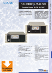
2.
MILA Infrared Lamp Heating Furnace
The heating furnace uses a heating system, in which an infrared (far-infrared)
lamp is fixed at the focus of the paraboloidal reflector and reflects infrared
beams in parallel. The lamp is available in two types: a near infrared lamp (100
V, 1 kW/piece) with high energy density that can heat the sample to a high
temperature efficiently within a short time or a far-infrared lamp (100 V, 250
W/piece) suited to uniform heating. Being sealed in a quartz glass tube, these
infrared lamps generates no gas from the heating element and allows clean
heating. The furnace body is made of aluminum and is cooled with water to
allow heating to a high temperature.
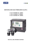
• MILA heating sample assembly
As shown in Fig. 1, the sample assembly is sealed airtightly with O-rings on
both ends of the transparent quartz glass tube and is fixed to the
water-cooled aluminum alloy flange. The sample, set on the transparent
quartz glass holder, is accommodated in the transparent quartz glass tube
and is heated with the infrared lamp (near-infrared, far-infrared) outside of
the transparent quartz glass tube.
When the near-infrared lamp is used, the energy in the wavelength region
(0.9 mm or more) irradiated with the near-infrared lamp transmits the
transparent quartz glass tube by 95% or more and heats only the sample by
radiation, making it suited to high temperature, short time processes.
- { PAGE } -
Evacuation port
Quartz sample holder
Sample observation port
T
Infrared lamp
Jig stopper
Thermocouple inlet port
O-ring
Sample moving flange axis
Sample heating system
- { PAGE } -
3. Evacuation System (option)
Ultimate pressure
10 to 4 Pa (room temperature no-load pump head)
Air-cooled oil diffusion pump 50 L/sec
Oil rotary pump
20 L/min
Power requirements
100 V, single phase, 0.35 kW
Weight
Approx. 16 kg
Outside dimensions
346 mm wide by 316 mm deep by 350 mm high
4.
Heated Sample Observation System (option)
Components: CCD camera, macro lens, XYZ adjustment stage
Observation port
CCD camera effective pixel/390,000 pixels
Magnification on the monitor/maximum 150x (on 17” monitor)
17” color monitor
5.
Gas Flow Unit (option)
Float type flow meter (fixed to the side of the basic unit with metal fixture)
* The gas specie and gas flow rate are to be specified before fabrication
(Up to maximum 3 units can be added.)
6.
Cooling Water Circulation Unit (option)
Cooling capacity
1700/1900 kCal/hr
Power requirements
200 V, three phase, 50/60 Hz
Power capacity
3.5 kVA
Weight
Approx. 85 kg
Outside dimensions
550 mm wide by 450 mm deep by 950 mm high
7.
Cooling Water Flow Switch (option)
Installed at the furnace cooling water outlet port.
If the cooling water is shut off or its flow rate becomes lower than the setting,
the heating furnace is shut down.
- { PAGE } -
8.
Front panel of MILA
Heating sample assembly
OMRON E5AR
Sample moving flange
HEAT lamp/HEAT ON SW
RESET SW
Thermocouple
Photo 1 MILA front panel
- { PAGE } -
9.
Rear Panel of MILA
Thermocouple output terminal for recorder
Flow switch terminal
Fuse socket
Evacuation discharge port
Auxiliary terminal
GAS OUTLET
T
Acryl cover
Cooling water inlet/outlet port
Earth terminal
T
200 VAC power input
6mm ID x 11mm OD braided hose joint
Photo 2 Rear panel of MILA
- { PAGE } -
T
9-1 Standard accessories in the rear side of MILA-5000 UHV
(1) ICF-70 Flange
(2)Bolts with hexagon head screw
(3)Gasket
・9-2 Setting way of the flange
・9-3 setting way of the gasket
*Please tighten in the opposite angle in installing the gasket.
Please tighten so that power is evenly applied to all bolts.
There is a possibility of some leak if you don’t.
- { PAGE } -
10. Names and Functions of Components
10.1 Main Controller Front Panel
③Interlock light
⑥GAS IN LET
②Sample outlet port
①System Main power
⑤HERT/RESET button
④Temperature controller(E5AR)
①
②
③
Main power
Main power of this system. Turning on the power turns on the power to the
temperature controller.
Sample outlet port
Open the thumb nut and set the sample holder and light shield.
Interlock light
TS_SW light and FLOW_SW light. The light is on when there
is no trouble
If either interlock light is off, check the cooling water flow
switch or other interlock (both are options). With the standard
model (when no option is provided), LOW SW and AUX
terminals on the rear of the system are shorted.
- { PAGE } -
Factory setting
{ EMBED Visio.Drawing.5 }
FLOW SW
If the optional cooling water flow switch was
ordered, connect the cooling water flow
switch cable here.
AUX
If any other interlock is added as option,
connect it to this switch.
E5AR temperature controller
Refer to the E5AR-T program type digital temperature controller for how to
operate the temperature controller.
⑤ HEAT/RESET button
{
EMBED HEAT button
Visio.Drawing Pressing the HEAT light turns the light red if the interlock is
.5 }
normal. Heating can be started with RUN on the temperature
controller when the HEAT light is on. If the light does no come on
when pressed, check the interlock (cooling water, AUX).
If the HEAT light does not come on
① Cooling water interlock faulty (FLOW switch terminal block
on the rear of the system)
Check cooling water.
If the optional flow switch was not ordered, it has been
shorted with a short pin.
② Other interlock faulty (AUX terminal block on the rear of the
system)
Check if interlocks are normal.
If optional interlocks have not been ordered, it has been
shorted with a short pin.
③ Overheating fault, thermocouple burnout
If SUB2 is lit in excess of the overheating set value on the
temperature controller, the HEAT light goes off. Check the
overheating set value. Also check if the thermocouple is
intact.
Check if the sample outlet port is open.
RESET button
④
- { PAGE } -
* In case of emergency (to stop heating), heating can be stopped by pressing
the RESET button. (The program does not stop.)
- { PAGE } -
10.2 Rear Panel of Temperature Controller
③ Terminal block
① 200V AC input
①
② Earth
④USB communication port
Power input
Connect your power board (200 VAC, single phase, 20 A
or more) to the MILA5000 AC200V INPUT terminal
block.
* In connection, retighten the terminal. If the terminal
screw is not tightened firmly, it will be overheated,
causing fire. So be careful.
②
Earth
Connect the earth wire as shown in the photo.
③
Terminal blocks
{ EMBED Visio.Drawing.5 }
1. TC (+)
It is not necessary to connect a thermocouple. (Connect it when it is
- { PAGE } -
desired to acquire the thermocouple output to a recorder or other.)
2. TC (-)
It is not necessary to connect a thermocouple. (Connect it when it is
desired to acquire the thermocouple output to a recorder or other.)
3. F S (Flow Switch)
Connect the cooling water flow switch cable. (option)
If the flow switch was not ordered, it has been shorted before shipment
from the factory.
4. AUX
Connect the cable for other interlock (only when the optional interlock
was added). Shorted before shipment from the factory.
④ USB port
Used when setting the temperature program or thermocouple from
the personal computer.
* For the communication with the personal computer, refer to
the operation manual for the MILA control software
CX-THERMO.
- { PAGE } -
11. Setting the Sample Holder
{ EMBED Visio.Drawing.5 }
Photo Sample moving flange
①
Pass the heat shield through the sample holder.
Set the heat shield between the heat shield stopper of the sample holder and
the
* Never touch the quartz sample holder with bare hands. If the quartz glass
is heated with water or oil on it, it will be devitrified.
If it is stained with water or oil content, wipe it off clean with alcohol.
{ EMBED Visio.Drawing.5 }
Photo Thermocouple set in position
- { PAGE } -
②
③
Pass the thermocouple fixed to the sample moving flange through the
sample holder and pull the platinum ribbon on the end of the thermocouple
onto the sample stage.
Fix the sample holder with the sample holder fixture so that the stage is set
in a horizontal position.
* Do not tighten the sample holder metal fixture excessively. The quartz
glass sample holder may be damaged. Just tightening the setscrew until
the setscrew does not move will do.
* Damage caused by excessive tightening is not covered by warranty.
- { PAGE } -
Specifications of E5AR-T Temperature Controller
Input unit
• High speed sampling
• High accuracy/high resolution
Sampling
: 50 ms
period
Accuracy
: Thermocouple
± 1 digit or less (± 0.1% PV or ± 1°C,
whichever greater)
Platinum
± 1 digit or less (± 0.1% PV or ± 0.5°C,
thermoresistance whichever is greater)
Analog
(± 0.1% full scale) ± 1 digit or less
(Refer to Appendix: Specifications for exceptions.)
Input
: 1/100°C
resolution
(Pt100: 0.01°C resolution from - 150.00 to 150.00°C)
High speed sampling and high accuracy/high resolution have been realized
simultaneously, allowing control with high accuracy high speed response
according to application.
• Multi-input
An abundant input range from temperature input to analog input is available.
Temperature : Thermocouple K, J, T, E, L, U, N, R, S, B, W
input
Platinum thermoresistance Pt100
Analog
: Current input 4 to 20 mA, 0 to 20 mA
input
Voltage input 1 to 5 V, 0 to 5 V, 0 to 10 V
• Multi-point input
Model E5AR-T is available in 2-input type and 4-input type and Model
E5ER-T is available in 2-input type.
Control unit
• Program
Up to maximum 32 programs can be created, in which the target value, time,
PID group No., alarm group No., weight width higher/lower limit values,
number of program repeat times and program link destination No. are
registered.
The target value, time, wait valid, and segment output can be set for each
segment.
• PID group
- { PAGE } -
Setting data for PID control (PID values, variable control limit value, and
automatic selection range higher limit value) can be created up to maximum 8
groups.
Each PID group directly specifies with the PID group No. in the program, but
also can automatically select the PID group that changes over according to the
current value, deviation and target value.
• Abundant control modes and control functions
One unit of the 2-input type or 4-input type permits coordinated operation. The
slave type controller that has been necessary is no longer necessary.
The position proportional type permits selection of floating control and closed
control. In floating control, position proportional control can be made without
using a potentiometer.
Output unit
• Multi-output
Multi-output compatible with current output and voltage output (pulse) is
available.
• High resolution
Resolution of current output
0 to 20 mA
: Approx. 54,000 resolution
4 to 20 mA
: Approx. 43,000 resolution
- { PAGE } -
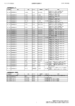
• Table of Inputs
Set value
Input type
1
2
3
4
5
6
7
8
9
10
11
12
13
14
15
16
17
18
19
Pt100 (1)
Pt100 (2)
K (2)
J (1)
J (2)
T
E
L
U
N
R
S
B
W
4 to 20 mA
0 to 20 mA
1 to 5 V
0 to 5 V
0 to 10 V
Set range
(°C)
(°F)
-200.0 to 850.0
-300.0 to 1500.0
-150.00 to 150.00
-199.99 to 300.00
-20.0 to 500.0
0.0 to 900.0
-100.0 to 850.0
-100.0 to 1500.0
-20.0 to 400.0
0.0 to 750.0
-200.0 to 400.0
-300.0 to 700.0
0.0 to 600.0
0.0 to 1100.0
-100.0 to 850.0
-100.0 to 1500.0
-200.0 to 400.0
-300.0 to 700.0
-200.0 to 1300.0
-300.0 to 2300.0
0.0 to 1700.0
0.0 to 3000.0
0.0 to 1700.0
0.0 to 3000.0
100.0 to 1800.0
300.0 to 3200.0
0.0 to 2300.0
0.0 to 4100.0
One of the following ranges is displayed according to scaling.
-19999 to 99999
-1999.9 to 9999.9
-199.99 to 999.99
-19.999 to 99.999
-1.9999 to 9.9999
[Miscellaneous]
Communicating function
The temperature program and other important data can be transferred from the
personal computer to the temperature program via USB cable and monitored
during operation by using the supplied software CX-thremo. Refer to the
CX-thermo manual for the software specifications.
- { PAGE } -
Names of components of temperature controller E5AR
Names of components on front panel
• Model E5AR-T
{ EMBED Visio.Drawing.5 }
Initial window
{ EMBED Visio.Drawing.5 }
Components on initial window
① Indicating light
SUB1: SUB1 lights when heating is started normally.
SUB2: SUB2 lights if the overheating interlock is actuated. If heating test is
being made, SUB1 goes off simultaneously with SUB2 coming on.
② 1st display
Displays the actual thermocouple temperature.
③ 2nd display
Displays the programmed temperature.
④ 3rd display
Displays the program pattern No. and step.
How to input the temperature program
The following program is set.
{ EMBED Visio.Drawing.5 }
* The method of inputting the program above is described below as an example.
Temperature program inputting procedure
(1) Specify a PTN No. to use using the PF2 key. PTN1 is specified in the photo
below.
(2) Create a temperature program.
{ EMBED PBrush }
1. Press the Level key in the initial window to
transfer control from “Operation Level” to
“Program Setting Level”. Specify program No.
“1” with “prgm: Edit program”.
Up to maximum 32 programs can be created.
A total of 256 steps can be registered.
(Maximum 16 programs can be created (No. 1
- { PAGE } -
to No. 16) and maximum 16 steps can be
input.)
To change the maximum input number of
programs, use the supplied software
CX-thermo.
{ EMBED Visio.Drawing.5 2.
}
Press the Mode key for less than a second and
select “s-no: number of segments”. Press the
Up key and set an arbitrary number of
segments. The number of segments is “6” in
the case of the segment above.
“Segment” is the total number of steps of the
temperature program.
{
EMBED 3.
Visio.Drawing.5 }
Press the Model key, select “seg.n: Edit
segment” and press the UP key to select “1”
from “end”.
{
EMBED
Visio.Drawing.5 }
{ EMBED PBrush }
4.
Press the Mode key and select “sp:Segment target
value”. Press the Up key to set the target value at
“200.0”.
(Set the actual ultimate target temperature.)
- { PAGE } -
{
EMBED 5.
Visio.Drawing.5 }
Press the Mode key twice and select “time:
Segment time”. Press the Up key to set time at
“1.00”.
(Input the actual target elapse time of each step.)
Press the Mode key to display the Pr window, but
it is not necessary to input. Input will be
invalidated. The input value is 0.
Pr window
In heating with this temperature controller, time
or gradient is set. If gradient is set, the Pr value
will be validated.
Time has been set before shipment from the
factory, so that it is not necessary to input it in the
Pr window.
{
EMBED 6.
Visio.Drawing.5 }
Press the Mode key and select “wait: Wait
effective”.
is turned “off”.
{
EMBED 7.
Visio.Drawing.5 }
Press the Mode key 3 times to return control to
“segn: Edit segment” The segment No.
automatically becomes “2”
(Repeat this step up to the last segment. Up to
segment 6 with the above program.
8.
Press the Mode key and select “sp: Segment target value”. Press the UP key
to set the target value at “800.0”.
9. Press the Mode key twice and select “time: Segment time”. Press the Up
key to set time at “1.30”.
10. Press the Mode key and select “wait: wait effective”. Turn it “off”,
11. Press the Mode key three times to revert to “segn: Edit segment”. The
segment No. is automatically set at “3”.
When input of temperature and time is completed to the last segment, the
window displays [END], thereby temperature program input being
completed.
- { PAGE } -
{ EMBED Visio.Drawing.5 }
* Refer to the OMRON E5AR-T User’s Manual for more information about
the method of inputting the temperature program.
How to input (register) PID values (when manually inputting a value)
PID values can be registered up to a total of 8 patterns.
How to register
{ EMBED PBrush }
1.
Press the Level key 4 times in the initial
window.
Specify a PID No to use with the UP/DOWN
key.
Press the Mode key once.
2.
3.
{ EMBED PBrush }
4.
Input PID values.
{ EMBED Visio.Drawing.5 }
5.
Input I value.
- { PAGE } -
{ EMBED Visio.Drawing.5 } 6.
Input D value.
To make heating test
① Press the PF2 key to select a program pattern to use.
② Holding down the PF1 key starts heating. To stop heating, hold down the
PF1 key again.
Specify PID values and alarm to use during heating test.
{ EMBED Visio.Drawing.5 Input a PID No. to use.
Input a PID No. to use, 0 to 8.
}
In the photo at left, PID No. 1 is specified.
(PID has a total of 8 patterns.)
{ EMBED Visio.Drawing.5 Input an alarm to use No. 1 to 4.
Up to 4 alarm Nos. can be registered in total.
}
In the photo at left, alarm No. 1 is specified.
(Example) Alarm 1 = 1200°C
Alarm 2 = 1000°C
Alarm 3 = 800°C
Alarm 4 = 500°C
If the alarm setting is registered as shown above
and alarm No. 1 is specified, heating to 1200°C has
been set.
Refer to the alarm temperature setting method.
Using PID pattern
• When running a heating/holding program with one PID
① Press the Level key in the initial window.
② Press the Mode key 3 times.
③ Specify a PID pattern No. to use. Up to a total of 8 patterns of PID can be
registered.
* Holding down the PF1 (RUN) key starts heating test using the specified
PID
- { PAGE } -
Basically, once PID values are calculated by auto tuning, temperature can be
increased/held with one PID
, except special temperature recipe.
Procedure
(1) Set sample.
(2) Start heating.
(3) Heating ® holding Auto tuning during holding
(4) PID values being used are automatically calculated.
- { PAGE } -
Auto tuning (AT)
{ EMBED Visio.Drawing.5 }
Press the Level key twice.
Change display ② from “OFF” to “0” or
“1 to 8” with the up/down key to start AT.
If AT is started by specifying “0”, the
display ① blinks and the PID group No.
now being used appears at display ②.
With completion of AT, the display ①
stops blinking.
If “1 – 8” is specified, the PID value of the
specified PID group No. is changed.
For more information about the method of
AT operation, refer to the OMRON
E5AR-T User’s Manual.
AT (Auto Tuning)
• AT automatically sets optimum PID constants for the target value when
executing. This system employs the limit cycle method, which finds the
characteristics of an object to control by changing the control variable.
① Set program
④ AT end
② Program executed
⑤ Time
③ AT start
• During AT, segment operation, such as change of set data, hold/hold resetting,
advance, back, etc., cannot be performed.
• AT will be stopped if “Run/Reset” is “Reset” (when “action at resetting” is
“control stop”) or is set in the manual mode. AT cannot be executed during
resetting (when the “action at reset” is “control stop”) or in the manual mode,
• When executing AT, specify “0” or when executing AT by specifying the PID
group No., specify “1 to 8”.
• The result of AT is reflected in “Proportional band”, “Integral time” and
“Differential time” of the PID group No. specified at AT of “PID set level”.
When “Action at reset” is “Constant value control”, the action is as follows.
• If “Run/Reset” is set at “Reset” during AT execution during run, the current
target value is changed over to a constant value SP after AT has ended.
- { PAGE } -
• If AT is executed during resetting and “Run/Reset” is set at “Run” during AT
execution, the set program will start after AT has ended for the set value SP.
• Description of AT Actions
{ EMBED PBrush
}
¯
{ EMBED PBrush
}
¯
{ EMBED PBrush
}
Changing “AT execution/stop” from OFF to 0 starts AT.
During execution, the 1st display of “Execute AT/Stop”
blinks and the 2nd display shows the PID group No.
currently being used for control. With completion of AT,
“Execute AT/Stop” is turned off and the display stops
blinking.
AT is executed and the following display appears
1st display: Blinking display that shows that AT is being executed.
2nd display: The display changes over to the selected PID group No.
¯
{ EMBED PBrush To stop AT, specify “off : Stop AT”.
}
{ EMBED PBrush
}
If control is shifted to operation level during AT execution
and “Current value/Target value” is set, the 2nd display
blinks, indicating that AT is being executed.
• During execution of AT, “Communication write”,
“Run/Reset”, “AT execution/stop”, and “Auto/Manual”
can be changed. Other set data cannot be changed.
• If Reset is set with “Run/Reset” during execution of AT,
AT is stopped to stop operation if “Action at Reset” is
“Control Stop”. Even if Run is set with “Run/Reset”
again, AT does not restart.
- { PAGE } -
• If any input fault occurs during execution of AT, AT is
stopped and is executed again by resetting input error.
How to set overheating (alarm)
{ EMBED Visio.Drawing.5 }
{ EMBED PBrush }
① Press the Level key 3 times in the initial
window.
The photo at left shows, pattern No. 1
overheating setting.
② Press the Mode key.
- { PAGE } -
Select the alarm pattern No. with the
UP/DOWN key.
(Alarm can be set up to 4 patterns.)
The photo at left shows the overheat
setting of alarm setting temperature No. 1
Press the Mode key.
{ EMBED Visio.Drawing.5 }
Input the overheat setting temperature with the
UP/DOWN key.
* On the photo at left, the overheat setting
temperature is 0°C.
SUB2 lights because the overheat setting
value is below room temperature (below
PV value). The overheat interlock is
actuated.
Input a temperature arbitrarily.
If the overheat setting temperature is
exceeded during heating test, heating will
be stopped and the lamp is turned off.
Simultaneously with heating being
stopped, SUB1 goes off and SUB2 comes
on. Heating cannot be made if the actual
temperature is in excess of the overheat
setting value.
Heating is ready when the creation of the temperature program, registration
and specification of PID, and setting and specifying of overheating are
completed. Heating can be started by holding down the PF1 key for a while.
* For emergency stop and heating stop, hold down the PF1 key or press the
RESET button.
* If the set values are lost (unknown) during input (to revert to the initial
window), press the Level key several times to revert to the initial window.
- { PAGE } -
Other functions
How to set thermocouple
Hold down the Level key. The window is changed over.
{ EMBED Visio.Drawing.5 }
Set the thermocouple with the
UP/DOWN key.
Example of setting
① K thermocouple ® 2
② R thermocouple ® 11
Upon completion of setting, hold down
the PF2 key to revert to the initial
window.
Refer to the OMRON E5AR-T User’s
Manual for more information about the
thermocouple setting.
Changing over AUTO heating and MANU heating
Press the Mode key 12 times in the initial window.
Change over AUTO or MANU with the up/down key.
The mode is changed over to MANU several seconds after MANU is selected.
AUTO: Heating by a specified temperature program
MANU: Regulate the output with the UP/DOWN key.
If MANU is selected, control the output with the UP/DOWN key. (Output can
be set during and before heating.)
To select the AUTO mode again, press the Mode key 12 times in the window
shown below and select AUTO with the UP/DOWN key.
The photo shows MANU 100% output.
- { PAGE } -
Setting the unit of program time
{ EMBED Visio.Drawing.5 Hold down the Level key in the initial window.
Press the Mode key.
}
Press the Mode key 7 times in the window at left.
{ EMBED PBrush }
Set “hour, minute”, “minute, second” and “minute,
second, 100 millisecond” using UP/DOWN key.
In the window at left, “minute, second” are set.
{ EMBED PBrush }
In the window at left, “hour, minute” are set.
{ EMBED PBrush }
In the window at left, “minute, second, millisecond”
are set.
*
For more information about how to set the unit
of program time, refer to the OMRON
E5AR-T Users Manual.
Manual Setting
For manual setting of PID constants, set values in “Proportional Band”,
“Integral Time” and “Differential Time”.
[Supplement]
• If control characteristics are already known, set PID constants directly. Set PID
constants with “Proportional Band”, “Integral Time” and “Differential Time”.
• Set PID constants I (integral time) and D (differential time) at 0 to make
proportional action. The manual reset value has been set at 50% as the initial
value, so that the center of the proportional band is the target value.
When P (proportional band) is changed
Increase
Target value
Slow rise and longer settling time,
but no overshooting
- { PAGE } -
Decrease
Target value
Overshooting and hunting, but set
value is attained sooner to stability.
When I (integral) time is changed
Increase
Target value
Decrease
Target value
Overshoot and undershoot occur.
Hunting occurs.
Shorter rise time.
When differential time (D) is changed
Increase
Target value
Decrease
Target value
Longer time before target value is
attained
Longer settling time,but smaller
hunting, overshoot and undershoot
Shorter overshoot and undershoot
settling time, but minor hunting in
its own change.
Higher overshoot and undershoot
and more time is required to restore
the target value.
• Application
Changing PID at each step with a multi-step heating/holding program
Multi-step PID: PID is changed over depending on a specified temperature
range.
* Basically, temperature can be controlled with one PID by using auto tuning.
Conduct auto tuning first.
Automatic selection of PID group
PID group
1
2
3
4
Automatic selection range higher limit value
200.0
400.0
500.0
600.0
- { PAGE } -
¬ PV (current value)
5
6
7
8
700.0
800.0
1000.0
1300.0
¬ Internal fixed value
: 999.9% FS
In the example above (when “PID group automatic selection data” is “PV”),
the following PID values are effective.
When PV£200.0°C
: PID group No. 1
When 200.0<PV£400.0°C : PID group No. 2
Set the “PID group automatic selection range higher limit value” in such a way
that the set values become higher in increasing order of the PID group Nos.
However, the PID group No. 8 is internally fixed at “automatic selection range
higher limit value=999.9%FS”
To prevent chattering when changing over the PID group, hysteresis can be set
with “PID group automatic selection hysteresis”.
The PID group automatic selection data can be selected from PV, DV
(deviation) and SP (current target value).
- { PAGE } -
Set data
PID group No.
PID group No. 1 – 8
automatic selection range
higher limit value
PID group automatic selection
data
PID group automatic selection
hysteresis
Set range
0: Automatic selection
1 to 8: PID group No.1 to 8
- 19999 to 99999
Unit
-
Initial value
0
EU
1450.0
0: PV, 1: DV, 2: SP
-
0: PV
0.10 to 99.99
%FS
0.50
① Press the Level key 4 times in the initial window.
② Press the Model key 6 times.
③ Specify PID No. at 0.
{ EMBED Visio.Drawing.5 }
Press the Level key 4 times in the initial
window.
The window at left appears.
Specify the PID No.
(Example)
PID group
1
2
3
4
5
6
7
8
Automatic selection range higher limit value
200.0
400.0
500.0
600.0
700.0
800.0
1000.0
1300.0
- { PAGE } -
¬ PV (current value)
¬ Internal fixed value
: 999.9 FS
{ EMBED PBrush }
Set the temperature range of PID. No.1.
For example, input 200°C in the table.
Input PID. No. 2 to 8 in the same manner as
above.
For more information about how to change over PID, refer to the OMRON
E5AR Users’ Manual.
* Basically, temperature can be controlled with one PID constant. Change
PID at each step only in a special case. Calculate PID by auto tuning.
- { PAGE } -
Other functions that are used often
Hold
Initial window in heating ®
Press Mode key twice ®
{ EMBED Visio.Drawing.5
}
Change over to ON with
UP/DPWN key.
HOLD light comes on at
HOLD.
{ EMBED Visio.Drawing.5 }
® To terminate HOLD, turn off HOLD with the UP/DOWN key again.
ADVANCE
Initial window in heating ®
Press MODE key twice. ®
{ EMBED Visio.Drawing.5 { EMBED Visio.Drawing.5 }
}
Change over to ON with
UP/DOWN key.
{ EMBED Visio.Drawing.5 }
® STEP is changed over to the next step simultaneously with ON.
For more information about the settings of each component, refer to Model
E5AR-T Users’ Manual for the Program Type Digital Controller
- { PAGE } -