1
Bachelor thesis – MiS20, the robotic soccer simulator
Hans Dollen
Wim Fikkert
3.5.1.4. Object data
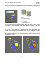
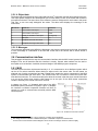
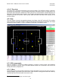
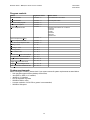
The bottom panel will display the exact robot and ball vector31 information and the object speed to the user.
This object speed consists of two wheelspeeds (one for each wheel) in case of the robots and consists of
one speed for the ball. The team colors of the robots are set as a background for each robot in this panel.
That way, a user can easily distinguish the robots. The table below displays the meanings of the
mnemonics.
Mnemonic
Stands for
Is listed in
x
X axis location of this object
meters
y
Y axis location of this object
meters
h
Heading or orientation of this object
0 through 2 pi
s
Ball speed
m/s
wL
wheelspeed of the left robot wheel
m/s
wR
wheelspeed of the right robot wheel
m/s
3.5.1.5. Messages
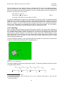
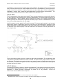
The messages generated by the MiS20 are displayed in the similary named panel on the right. An example
of such a message is a notification of the user that a team has to be chosen after a referee button is
pressed.
3.6. Communication interface
This paragraph will describe the way the communication interface with the Mi20 control systems has been
designed. First we will describe what this interface is exactly. Second, what methods can be used to
accomplish such an interface. And third, the actual design of this MiS20 program component.
3.6.1. Mi20
The Mi20 system has been implemented entirely in C. It is constructed to be a distributed system which
can be run on various machines without having to adjust much in the source code. For this reason, an
elaborate set of socket connections has been created which enable the various components of the Mi20
system to communicate with each other32. The sockets make use of mutexes to inform the receiver that
new data has been sent. The second unusual point about the sockets is that the server sends information
to a port on the client's host, and the client listens on its own port. So the Mi20 socket connections
“behave” differently from normal client-server sockets.
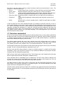
In chapter one, figure 1.1 illustrated which part of the Mi20
distributed system a simulator will replace. Figure 3.6 displays
the interface our Mission Impossible Simulator will have to
comply to in order to communicate succesfully with the Mi20
control systems.
Figure 3.15. The Mi20 communication interface33
31
. A mathematical vector contains x and y positions, a heading and a timestamp.
. Our design document includes a detailed description of this Mi20 component communication.
33
. A more exact communication interface diagram can be found in the design document, reference [B3].
32
31