1
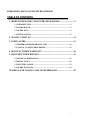
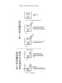
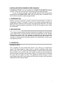
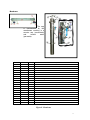
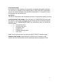
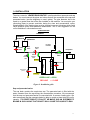
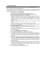
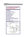
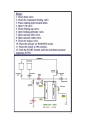
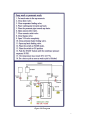
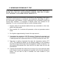
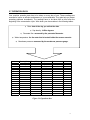
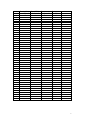
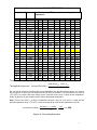
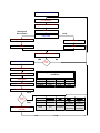
OPERATOR’S MANUAL FOR 50 GPH MODEL
LEADER EVAPORATOR LTD.
49 Jonergin Drive
Swanton, Vermont 05488
TEL. : (802) 868-5444
VERSION : 25 JAN. 2006
www.leaderevaporator.com
OPERATOR’S MANUAL FOR MICRO OSMOSIS
TABLE OF CONTENTS___________________________
1. MODE D’EMPLOI DE CONCENTRATEUR MICRO ............................ 5
1.1 INTRODUCTION ....................................................................................... 5
1.2 BACKGROUND.......................................................................................... 5
1.3 OPERATION ............................................................................................... 5
1.4 INSTALLATION....................................................................................... 12
2. YEARLY START UP................................................................................... 14
3. USER’S GUIDE ............................................................................................ 15
3.1 MEMBRANE PERMEABILITY TEST ................................................. 16
3.2 ANNUAL CLOSING PROCEDURE ...................................................... 19
4. MANUFACTURER WARRANTY ............................................................ 20
5. EQUIPMENT DESCRIPTION................................................................... 19
5.1 PHYSICAL DIMENSIONS...................................................................... 19
5.2 FRONT PANEL......................................................................................... 22
5.3 ELECTRICAL BOX ................................................................................. 23
5.4 OPERATION DATA................................................................................. 24
WASHING AND TAKING CARE OF MEMBRANES ............................... 28
2
LIST OF FIGURES__________________________
FIGURE 1. OSMOSIS AND REVERSE OSMOSIS ........................................................... 4
FIGURE 2. FUNCTIONING (MICRO OSMOSIS 50 GPH).............................................. 6
FIGURE 3. THERMOSTAT ......................................................................................... 7
FIGURE 4. PRE FILTER ............................................................................................ 7
FIGURE 5. LOW PRESSURE SWITCH .......................................................................... 8
FIGURE 6. PRESSURE GAUGES ................................................................................. 8
FIGURE 7. PRESSURE PUMP ..................................................................................... 9
FIGURE 8. MEMBRANE .......................................................................................... 10
FIGURE 9. INSTALLATION GUIDE ........................................................................... 12
FIGURE 10. PICTOGRAM ........................................................................................ 17
FIGURE 11. REVERSE OSMOSIS UNIT ..................................................................... 21
FIGURE 12. FRONT PANEL ..................................................................................... 22
FIGURE 13. ELECTRICAL CONTROL BOX FOR 50 GPH........................................... 23
FIGURE 14. OPERATION DATA ............................................................................... 24
FIGURE 15.PRODUCTION SHEET FOR REVERSE OSMOSIS ...................................... 26
FIGURE 16. CORRECTION FACTOR SHEET ............................................................. 28
3
Figure 1. Osmosis and reverse osmosis
4
1. MODULAIRE MICRO-OSMOSIS USER’S MANUEL
CONGRATULATIONS! You just acquired an LEADER EVAPORATOR reverse
osmosis. This proves your interest in new technologies and beautiful things.
In fact, you have purchased a technologically advanced unit built by skilled
professionals at A. Pellerin & Fils Ltée, who bring many years of research to the
use of reverse osmosis in maple syrup production.
1.1 INTRODUCTION
Reverse osmosis is a process by which a solution’s natural tendency to scatter its
components uniformly is reversed. It occurs in the reverse osmosis because an
applied pressure forces the water through a semi-permeable membrane. The water
that does not pass through the membrane is left with all the sugar and thus called
the concentrate.
1.2 BACKGROUND
The reverse osmosis process has been observed and studied for more than 250
years. Father Nolet, a French scientist, carried out experiments on the osmosis
phenomenon around 1748. The scientists realized long ago that this process
could be reversed and that many applications could flow from this research. The
principle of reverse osmosis has been applied to the desalination of water since
the beginning of 1960.
1.3 OPERATION
How does it work?
This is probably the first question that came to your mind as you opened this
manual. The sap provided by maple trees is a solution containing mostly water
(96% to 98%), 2% to 3% sugar and small quantities of mineral salts, proteins and
other elements such as aroma. Sap is the solution in which you will increase the
amount of sugar in relation to the quantity of water. This will be done by extracting
the water from the maple tree sap. This separation process will give a more
concentrated sap solution (concentrate) and the portion of water, which has been
subtracted from the sap (permeate).
5
FLOWCHART MICRO-OSMOSIS
OUTPUT
Thermostat
To permeate basin
T
Permeate
Flowmeter
T
Output
PUMP
MEMBRANE
Valve V18
Input
Wash
P
Pump pressure
Membrane
Pressure
Filtre
Figure 2. Functioning (micro osmosis 50 GPH)
Sap and permeate basins
The sap basin contains the maple tree sap. The permeate basin is filled with
the water extracted from the sap during the concentration procedure. We
recommend that the sap and permeate basins be connected with a common
feeding pipe. We also recommend that the permeate basin be able to contain
at least twice the unit’s capacity. IT IS PREFERABLE TO PLACE THE
MAPLE SA P, EVAP ORATOR AN D PER MEATE BASIN S IN SUCH A WAY
THAT GRAVITY WILL CAUSE THE LIQUIDS TO RUN.
Sap and permeate pipes
A return permeate line is already installed, this line must be installed up to the
permeate basin. THE EVAPORATOR MUST BE INSTAL LED AT LOWE R
LEVEL IN SUCH A W AY THAT GRAVITY WILL CAU SE THE LI QUIDS TO
RUN.
Sap, permeate, drain and evaporator basin valves
Please note that the sap and permeate basins are not supplied by the
company. You must provided the valves and pipes that will be installed at the
output of your permeate and sap basin respectively, the flow of those basins
must be controlled by a valve located under each one. Also at the evaporator
input and for the drain valve.
6
Thermostat
This controller evaluates the liquid’s temperature as it penetrates the reverse osmosis.
The value is immediately displayed on a screen located on the reading panel. The
temperature must never exceed 49o Celsius (120o Fahrenheit). The programming
procedure of this thermostat is explained in the following way :
No. ITEM
1
No. SQUAD
Quantity
Description
01152443
1
JOHNSON CONTROL VACUUM PUMP THERMOSTAT (DIGITAL)
174087
4
ROUNDED HEAD ROBERTSON SCREW 6-32 X 1/2''
108006
4
LOCKNUT 6-32
Figure 3. Thermostat
Pre-filter
The sap is filtered by a 10 microns cartridge.
This clears it from any substance in
suspension. .
Figure 4. Pre filter
No. Item
2
3
4
5
6
7
8
9
No. Squad
04211138
04213457
04213294
PI450822S
04210250
04210226
5000309
04211010
Quantity
1
2
2
2
1
1
4
1
Description
SEDIMENT POT FILTER 10''
STAINLESS 316 ELBOW, 150 PSI 1/4"
NIPPLE STAINLESS 316 SCH40 3/4’’ X 1’’ (CLOSED)
FITTING PUSH-IN 1/4'' OD TUBE X 1/4’’ NPTF
PVC ELBOW 90 DEGREE 3/4'' MPT X 3/4’’ INS
PVC ADAPTER 3/4‘’ MPT * 3/4'' INS
HEXAGONAL STAINLESS BOLT 1/4-20 * 1’’
PREFILTER CARTRIDGE 10 MICRONS 9 7/8’’
7
Low Pressure control
This control ensures that dirt
or micro-organisms do not
obstruct the filters. If such
were the case, the machine
would stop by itself, thus
protecting the pumps and
membranes.
Figure 5. Low pressure switch
No. ITEM
No. SQUAD
Quantity
Description
10
01150143
1
LOW PRESSURE CONTROL P10-BC7C
11
01260746
1
LOW PRESSURE MOUNTING FOR R/O 1-13/16'' .010
12
01280430
1
PVC ADAPTER FOR PRESSURE SWITCH FOR R/O
13
5105093
4
SLOTTED MECHANICAL SCREW SS 6-32 X 1-1/4''
Pressure gauge (pump pressure) 0-300 PSI
This gauge allows you to read the pressure output, its value is
indicated on the reading panel.
Figure 6. Pressure gauges
No. ITEM
36
No. SQUAD
01090021
Quantity
2
Description
GAUGE 0-300 PSI GLYCERIN BACK CONNECTION
Pressure gauge (membrane pressure) 0-300 PSI
This gauge allows you to read the pressure at the membrane. This gauge is located at
the front panel which allows you to read the pressure in PSI or KPa. If this pressure
should drop below 12 psi (82,737kPa), the machine will stop by itself.
8
Pressure pump (4)
The filtered water is
pressurized with the
help of the pressure
pump. This gives the
sap the necessary
speed to clean the membrane surface automatically during the sap
concentration process. The same thing happens to the washing liquid
during the soap and recirculation washes.
# ITEM
14
15
16
17
18
19
20
21
22
23
24
25
26
No. SQUAD
96080242
04212065
01261143
01171145
01154156
01151157
04213457
04210250
01261142
AC13HH-440
4OMPU40
Quantity
1
1
1
1
1
2
2
1
1
1
1
1
1
Description
GRUNDFOS PUMP 10SQ10C-330 1C HP/240V 3’’DIA. 1-1/4
STAINLESS REDUCER 1 1/4’’ MPT* 3/4’’ FPT
ÈNVELOPE COVER FOR PUMP 3 1/2‘’
ADAPTER SS 1/4’’ COMPRESSION X 1/4’’ MPT
ELEC. NYLON CONNECTOR 1/2’’ NPT REMKE GREY
BUSHING 3 HOLES FOR CONNECTOR 01154156 .156’’
STAINLESS 316 ELBOW 150 PSI 1/4''
PVC ELBOW 90 DEGREE 3/4'' MPT X 3/4’’ INS
PUMP ENVELOPE 3 1/2’’ FOR MICRO OSMOSIS MAPLE GROVE
LIQUID INLET
LIQUID OUTLET
HEAVY DUTY CLAMP SINGLE PIN 4’’
STANDARD CLAMB GASKET BUNA-N 4’’
Figure 7. Pressure pump
9
Membrane
The sap
is concentrated by the
membranes resulting in a
sweeter sap (concentrate)
and
treated
water
(permeate).
No. ITEM
No. SQUAD
Quantity
27
01260004
1
Description
MEMBRANE 4'' X 40'' HYDRANAUTICS PVD1
28
01260449
1
ADAPTER 4'' HYDRANAUTICS VS AIRABLO (0,800-0, 0.750)
29
01260787
1
PLUG 4'' HYDRANAUTICS VS AIRABLO 5
30
01300066
2
O-RING 13/16'' ID 1'' OD 3/32'' MUR
31
01300135
2
O-RING 3/4'' ID 1'' OD 1/8'' MUR
32
01300574
1
O-RING 3 1/4'' ID 3 3/4'' OD 1/4'' WALL BANJO FILTER
33
01300576
1
O-RING 3 1/2'' ID 4'' OD 1/4'' MUR (COUVERCLE 4'')
51
PI091624S
1
ELBOW PUSH-IN 1/2’’ TUBE X 1/2’’ MALE NPT
52
04210352
1
PVC ELBOW 90 3/4’’ INS * 3/4’’ FPT
0
53
04213459
1
STAINLESS 316 ELBOW 150PSI 1/2’’
54
AC13HH-440
2
HEAVY DUTY CLAMP SINGLE PIN 4’’ (WITH ITEM 40MPU40)
55
04210225
1
PVC ADAPTER 1/2’’ MPT *1/2’’ INS
56
01040846
1
BALL VALVE 1/2’’ SS 2000 PSI NEW
57
04211603
1
ELBOW STAINLESS 90 DEGREE 1/2’’ MPT * 1/2’’ FPT
58
04213579
1
T STAINLESS 316 150 PSI 1/2’’ FPT
59
04213423
1
STAINLESS 316 REDUCER 150 PSI 1/2’’ MPT * 1/4’’ FPT
60
01172298
20’
61
01172296
1
62
04211797
2
NIPPLE STAINLESS 1/2’’ MPT * CLOSE
63
04211015
1
CLIP 1/2” A 1” HF-8
PIPE SS 5/16’’ OD #304 .035’’ WALL 20’
ADAPTER SS 5/16’’ COMPRESSION * 1/4’’ MPT
Figure 8. Membrane
10
Permeate flowmeter
As it comes out of the membrane, the permeate is run directly through this flowmeter.
The flow value is indicated on the reading panel in GPM. During the concentration
process, the liquid is directed to the permeate storage basin. It is essential to know
the permeate and concentrate flows.
VALVE V18 :
This valve is closed during the concentration process. It is open while washing or rinsing.
CONCENTRATION FU NCTIONING: Place the switch in CONCENTRATION mode and
the selector in ON position and push the start button until the membrane pressure
surpasses 20 PSI. PLEASE NOTE THAT: the manufacturer does not include the
following valves:
•
Osmosis inlet valve
•
Osmosis outlet valve
•
Evaporator valve
•
Bypass valve
•
Permeate and sap valves
•
Drain valve
STOP: The unit will stops when you select the SELECTOR OFF operation mode.
WASHING FUNCTIONING: Place the switch in WASH mode, the selector in ON
position and push the start button until the membrane pressure surpasses 20 PSI.
11
1.4 INSTALLATION
The micro osmosis ‘’LEADER EVAPORATOR’’ is delivered without permeate and sap
basins. You must connect the pipes and valves that will be connected at the sap and
permeate basins. (see the diagrams on user’s guide). The pipe diameter has to be
equal to or greater than that of the filter installed on the machine. You must plan your
connecting pipes to prevent restriction during the rinse and concentration cycles.
Watertightness of the feeding pipe must be checked to prevent vibrations which could
cause pressure pump and membrane deterioration. This is one suggestion for the
unit’s installation in concentration mode.
CONCENTRATION
PERMEATE
SAP
RESERVOIR
Permeate
flowmeter
Sap
Valve
Permeate
Valve
Evaporator
Evaporator
Valve
Outlet
osmosis
valve
OUTPUT
PUMP
Inlet
osmosis
valve
Bypass
Valve
Drain Valve
(close)
MEMBRANE
PERMEATE
RESERVOIR
Valve V18
OUTPUT
INPUT
GREEN LINE = OPEN
RED LINE
= CLOSE
Figure 9. Installation guide
Sap and permeate basins
The sap basin contains the maple tree sap. The permeate basin is filled with the
water extracted from the sap during the concentration procedure. We recommend
that the sap and permeate basins be connected with a common feeding pipe. We
also recommend that the permeate basin be able to contain at least twice the unit’s
capacity. IT IS PREFE RABLE T O PLACE T HE MAPLE SAP AN D PERMEAT E
BASINS IN SUCH A WAY THAT GRAVITY WILL CAUSE THE LIQUIDS TO RUN.
12
A well lit, well heated, well ventilated, isolated shelter for the machine should be
planned in the saphouse. The entrance door dimensions must be calculated
according to the machine dimensions (see section 5.1). The shelter should be
heated prior to delivery and installation of the machine. The durability of the electrical
components will depend on the feeding quality. Therefore, it is very important to
have your electrician check your installations to make sure that they comply with the
local electricity code standards.
13
2. YEARLY START UP
All the following procedures can be made with spring water (without Chlorine!) or well
water, as long as it is clean and does not stain.
Your machine has been filled with a glycol solution to prevent the membranes and other
components from freezing. The preparation of your system at the beginning of each
season must be carried out in the following way:
¾ Read the user’s manual completely.
¾ Call an electrician to connect the unit to an electrical source.
¾ Connect the unit to the maple sap, concentrate and permeate basins.
¾ Connect the permeate pipe beneath the membrane.
¾ Plug in the machine and rinse the unit following the same process as for
membrane rinsing with half the number of water gallons your unit can
concentrate in an hour. For example, if your machine has an 8 inches
membrane, thus a 600 gallons per hour (GPH) capacity, rinse it with 300
gallons of water.
¾ Perform a washing without soap, reaching a water temperature of 460C
(1150F).
¾ Do a second rinsing cycle as soon as the washing cycle is finished.
¾ Do a second washing without soap. It is very important to reach the water
temperature mentioned before.
¾ Do another rinsing cycle as soon as the washing cycle is finished.
¾ Do a third washing cycle, this time adding the soap. Make sure to reach a
temperature of 460C (1150F).
¾ Do a final rinsing cycle with half the number of water gallons your unit can
concentrate in an hour.
¾ Carry out a permeability test of membranes
1. Put 10 gallons (approximately) of water in the sap reservoir.
2. Concentrate the permeate at 100 PSI pressure. Returning the permeate and
concentrate to the sap basin. To do that, you must position the valves and
pipes in washing soap cycle, adjust the pressure to 100 PSI by closing the
valve V18.
3. Take down a reading of permeate flow when the temperature reaches 210C
(700F). This reading will indicate you the filtration capacity of your membrane
only without imply another factor such as temperature, biofilms or bacteria.
You can compare the permeate flow value with the one taken when the unit
was manufactured.
4. Compare the permeate flow value with the one taken when the unit was
manufactured or after you first utilisation during the season. You will evaluate
in this way the permeability of your membrane. This data will be your
reference for other successive tests.
You are now ready to concentrate maple sap.
14
3. USER’S GUIDE
This manual was designed to help you work with your reverse osmosis. All of
these instructions are also printed on the front of your machine. (see the following
pictograms).
15
16
Figure 10. Pictogram
17
3.3 MEMBRANES PERMEABILITY TEST
IT IS VERY IMPORTANT THAT YOU REMEMBER TO TAKE THIS DATA
EVERY DAY YOU USE YOUR REVERSE OSMOSIS. THIS WILL ENABLE
YOU TO DETECT ANY OPERATIONAL DIFFICULTY.
The filtration process and the membrane’s performance vary depending on the type of
membrane, exerted pressure on membrane, sap temperature, percentage of sugar in
the concentrate, and presence of other components such as bacteria, biofilm and
mineral salts. Therefore, it is important to maintain similar test conditions for all
samplings. To do so, we recommend that you use the following method:
1. Prepare a basin full of permeate obtained from sap concentration or from clear,
detritus free spring water.
2. Rinse machine for 10 minutes with permeate so that only permeate remains
inside.
3. Put 10 gallons (approximately) of water in the sap reservoir.
4. Concentrate the permeate at 100 PSI pressure. Returning the permeate and
concentrate to the sap basin. To do that, you must position the valves and pipes
in washing soap cycle, adjust the pressure to 100 PSI by closing the valve V18.
5. Take down a reading of permeate flow when the temperature reaches 210C
(700F). This reading will indicate you the filtration capacity of your membrane
only without imply another factor such as temperature, biofilms or bacteria. You
can compare the permeate flow value with the one taken when the unit was
manufactured.
6. Compare the permeate flow value from your test (no 5) to the same test made
at the factory or when you operated your machine for the first time during the
season. You will then be able to establish the exact condition of your
membrane.
18
3.4 ANNUAL CLOSING PROCESS
All of the following procedures can be made with spring water (without Chlorine!) or
well water, as long as it is clean and does not stain. Use as much p ermeate water
as possible to store your machine.
1
Rinse your machine with half the number of water gallons it can concentrate
per hour.
2 Wash the machine with the amount of soap recommended and let the
temperature raise up to 460C (1150F). Soap = 4 ounces per membrane.
3 Rinse your machine with half the number of water gallons it can concentrate
per hour.
4 Wash the machine with ACID and let the temperature raise up to 460C
(1150F). The unit should soak as long as possible (maximum 1 month).
5, 6, and 7 Do another rinse and wash soap cycle followed by another rinsing
as you had done in the three first steps.
Do a permeability membrane test.
¾ Put 10 gallons (approximately) of water in the sap reservoir.
¾ Concentrate the permeate at 100 PSI pressure. Returning the
permeate and concentrate to the sap basin. To do that, you
must position the valves and pipes in washing soap cycle,
adjust the pressure to 100 PSI by closing the valve V18.
¾ Take down a reading of permeate flow when the temperature
reaches 210C (700F). This reading will indicate you the filtration
capacity of your membrane only without imply another factor
such as temperature, biofilms or bacteria. You can compare
the permeate flow value with the one taken when the unit was
manufactured.
¾ Compare the permeate flow value with the one taken when the
unit was manufactured or after you first utilisation during the
season. You will evaluate in this way the permeability of your
membrane. This data will be your reference for other
successive tests.
8 If your membrane is clean, continue on step # 9. If you are not satisfied with
the cleanness of your membrane, you can pursue this process on step # 4
or simply send back the membrane to be CLEANED at the factory.
9 Put 20 litres of permeate in the washing basin and 4 litres of glycol or
glycerine. Add a teaspoon of preserve-osmo and let the water flow for 15
minutes. Then, stop your machine and HEAT the room all year between 50C
and 100C.
P.S.: If the room is subject to FREEZING, put 10 litres of glycol or glycerine for each
4’’ x 40’’ membrane, 20 litres for each 8’’x 40’’ membrane and 30 litres for each 8’’x
60’’ membrane in the wash basin and let the liquid run inside the machine (see annual
storage with antifreeze).
19
4. MANUFACTURER WARRANTY
Reverse osmosis LEADER EVAPORATOR machines are guaranteed by their manufacturer
against all workmanship defects for a period of two complete seasons, starting on the
installation date of the machine. The manufacturer’s responsibility regarding this warranty is
limited to the repair or replacement of parts when he should consider it necessary to do so.
All replaced parts become the manufacturer’s property. A. Pellerin & Fils Ltée shall not be
held responsible for any damage or injury arising from negligence, abuse, improper handling
or installation.
20
5. EQUIPEMENT DESCRIPTION
5.1 PHYSICAL DIMENSIONS FOR (50 GAL) UNIT
Height: 52"
Width: 18"
Depth: 25"
52"
18"
25"
Figure 11. Reverse osmosis unit
21
5.5 FRONT PANEL
The reading panels were designed to meet your needs. They include the following items as
standard equipment
No. ITEM
34
35
36
37
38
39
10
41
42
43
44
45
46
47
48
49
50
No. SQUAD
01154173
01152443
01090021
01260893
RB233
01152476
01150143
01090025
04213577
04213457
PI010822S
PE08BI0500F-W
01301392
04210350
408005
PI011604S
04210581
Quantity
1
1
2
1
1
1,5
1
2
1
1
2
2
1
1
1
1
15
Description
CONTROL BOX FOR MICRO OSMOSIS 1 HP 240V
JOHNSON CONTROL VACUUM PUMP THERMOSTAT DIGITAL
GAUGE 0-300 PSI GLYCERIN BACK CONNECTION
NO VALVE FLOWMETER 2 GPM 5’’ PVC ADAPTER
RONDELLE ISOLANTE CAOUT. 7/16’’ ID 15/16’’ OD 7/16’’
ELECTRICAL WIRE 18/6 SOW (PRICE BY FOOT)
LOW PRESSURE SWITCH P10-BC7C
GAUGE BACK HOLDER 2 1/2’’
T STAINLESS 316 150PSI 1/4’’ FPT
STAINLESS 316 ELBOW 150 PSI ¼’’
FITTING PUSH-IN 1/4’’ HOSE X 1/4’’ MALE NPTF
TUBE PUSH – IN 1/4’’ OD WHITE FDA 120 PSI AT 150 F
POLYETHYLENE PNUMATIC TUBE 1/2 OD NATURAL 100’
0
PVC ELBOW 90 1/2’’ INS * 1/2’’ FPT
0
PVC ELBOW 90 1/2’’ FPT
ADAPTER PUSH-IN 1/2’’ TUBE X 1/2’’ MALE NPT
TUBE PVC 1/2"I.D. 200PSI(70F)-100PSI(122F) 300'
Figure 12. Front panel
22
5.6 ELECTRICAL BOX
8
10
No. ITEM
1
No. SQUAD
01150964
Quantity
1
Description
PVC BOX LUME 9 X 7 X 6.5 (220 X 170 X 150)
2
01151650
1
BACKPLATE FOR VACCUM AND WASHER
3
01150758
1
ELECTRICITY 2 METERS DIN RAIL 1 1/4"
4
01150757
1
ALUMINUM GROUND BAR 6' - 0
5
01151588
1
SCREW STRIP 300V 8 TERMINALS 4.25" LONG
6
01150727
1
MAGNETIC DP25-3 208-230 V/ 60 HZ.
7
01150625
1
OVERLOAD 8 AMP. TO 12 AMP. (TYPE TI 16C, TI 25C)
8
01153334
1
FLUSH PUSH BUTTON SPRING RETURN DANFOSS GREEN
9
01153379
1
CONTACT BLOCK 2 POSITION CONTACT NO+NO
10
01153351
1
SELECT SWITCH 2 POS. STAYPUT STANDARD HANDLE
11
01153684
1
TOGGLE SWITCHES 5 AMP 250VAC BLACK PLASTIC 2 WIR
12
01153200
2
LOG SLU 25S
13
01152325
1
MALE CARD 3 LEGS 15A, 250V LEV 615 PA EAG ,4866
14
01150985
15
15 FEETS WIRE 14/3 SJOOW (PRICE/FOOT)
Figure 13. Electrical control box for 50 GPH
23
5.7 OPERATION DATA
Your machine operation data has to be taken on every day of use. These readings are
essential to insure an efficient maintenance of your membranes. They also help you detect
operating problems immediately. The readings have to be taken half an hour after the
beginning of the concentration cycle. Write down your observations in the following tables :
1) Date: date of the day you collect the data.
2) Sap density: in Brix degrees.
3) Permeate flow: measured by the permeate flowmeter.
4) Water temperature: for the water that is treated inside the reverse osmosis..
5) Membrane pressure: measured by the membrane pressure gauge.
Density (Brix)
12
6 june 02
6 june 02
6 june 02
Sap
2.0
Flow (GPM)
Temperature
Permeate
3
7.5
7.5
Degrees F.
4
55
55
Pressure
PSI
5
200
400
Or
Test
T
C
Figure 14. Operation data
24
Density (Brix)
1
Sap
2
Flow (GPM)
Temperature
Permeate
3
Degrees F.
4
Pressure
PSI
5
25
Figure 15.Production sheet for reverse osmosis
CONCENTRATOR :
MEMBRANE MODELS
SERIAL No. :
Serial No._______________
1._____________________
1.______________________
Model __________________
2._____________________
2.______________________
Pump __________________
3._____________________
3.______________________
Motor____________________
4._____________________
4.______________________
HP MODÈL
Pumps
Serial Pump #
Motor serial #
PRIMING
PRESSURE # 1
PRESSURE #2
PRESSURE #3
PRESSURE #4
ACID AL
KALIN SOAPS OXYD
ANTS
Hydranautic PVD1
4 oz Acid-Osmo
4 oz Sani-Osmo
Filmtec NF70-BW30
4 oz Acid-Osmo
4 oz Sani-membrane
4 oz Oxy-membrane
Fluid System TFC
4 oz Acid-Osmo
4 oz Sani-membrane
4 oz Oxy-membrane
CONDUCTIVITY TEST
Membrane
Conductivity
Temperature
FLOW
PRESSURE
No.
Concentrate
o
Permeate
F
Permeate
Concentrate
PSI
1
2
3
4
TEMPERATURE CONTROL
Temperature 480C (1180F)
ELECTRICAL TESTS
Test dielectric
_________________OK
Total Amperage :
_______________Amps.
PROTECTION AGAINTS FREEZE
Density :_________________
Temperature :__________
Buyer’s Name :___________________
Salesman Name :__________________________
Order # :__________________
Technicien:_______________________________
Date________________________________
26
Fill up in case of malfunction
Our goal is to offer you an impeccable product. This is why every REVERSE
OSMOSIS machine is thoroughly inspected at the factory. We ask that you help us
improve our production methods by sending your comments to our production manager
at this fax number: (819) 828-3408.
Do not forget to send us the reverse osmosis production sheet with a description of the
problems encountered and their causes. We thank you in advance for your
collaboration.
Comments:
____________________________________________________________________
____________________________________________________________________
____________________________________________________________________
____________________________________________________________________
____________________________________________________________________
____________________________________________________________________
____________________________________________________________________
____________________________________________________________________
____________________________________________________________________
____________________________________________________________________
____________________________________________________________________
____________________________________________________________________
____________________________________________________________________
____________________________________________________________________
____________________________________________________________________
____________________________________________________________________
____________________________________________________________________
____________________________________________________________________
____________________________________________________________________
____________________________________________________________________
Technician : ___________________________
Date : _______________________
27
Correction factor for FLUID SYSTEM 8921S membrane
Temperature Factor
o
F
77
75
73
72
70
68
66
64
63
61
59
57
55
54
52
50
48
46
45
43
41
39
37
36
34
o
C
25
24
23
22
21
20
19
18
17
16
15
14
13
12
11
10
9
8
7
6
5
4
3
2
1
Corr. T
1,0000
1,0300
1,0610
1,0960
1,1260
1,1610
1,1960
1,2340
1,2720
1,3120
1,3540
1,3970
1,4420
1,4890
1,5370
1,5880
1,6410
1,6950
1,7520
1,8120
1,8730
1,9380
2,0050
2,0740
2,1470
Machine capacity GPH) corrected according to the
temperature
50
72
70
68
66
64
62
60
58
57
55
53
52
50
48
47
45
44
43
41
40
38
37
36
35
34
150
216
210
204
197
192
186
181
175
170
165
160
155
150
145
141
136
132
128
123
119
115
112
108
104
101
300
433
420
408
395
384
373
362
351
340
330
319
310
300
291
281
272
264
255
247
239
231
223
216
209
201
450
649
630
612
592
576
559
543
526
510
495
479
464
450
436
422
409
395
383
370
358
346
335
324
313
302
600
865
840
815
789
768
745
723
701
680
659
639
619
600
581
563
545
527
510
494
477
462
446
432
417
403
700
1009
980
951
921
896
869
844
818
794
769
745
723
700
678
657
636
615
596
576
557
539
521
503
487
470
800
1154
1120
1087
1053
1025
994
965
935
907
879
852
826
800
775
751
726
703
681
658
637
616
595
575
556
537
1000
1442
1400
1359
1316
1281
1242
1206
1169
1134
1099
1065
1032
1000
968
938
908
879
851
823
796
770
744
719
695
672
1600
2307
2240
2175
2105
2049
1987
1929
1870
1814
1759
1704
1652
1600
1549
1501
1453
1406
1361
1317
1273
1232
1191
1151
1112
1075
To calculate the capacity of your unit : We suggest you to proceed in the following way :
The application formula is : Corrected Flow (GPH ) =
(Flow (GPH ))550 F *(Corr .T )550 F
(Corr . desired Temp. 0 F )
We can take an example to illustrate the formula application with the table showed above. You need to
find out the flow of any unit at one temperature of 20C (360F) for example. You must take the flow value at
130C (550F) as a base value and multiply by the correction factor value (1.4420) at this temperature.
Finally, divide them by the correction factor value at the desired temperature.
Data : Flow at 130C (550F) = 50 GPH, Temperature correction factor at 130C (550F) = 1,4420, and the
desired temperature value = 20C (360F). So the correction factor value at this temperature is 2.0740.
Corrected Flow (GPH ) =
(50 GPH )550 F * (1.4420)
(2.0740)360 F
=
72.1
= 35 GPH
2.0740
Figure 16. Correction factor sheet
28
WASHING AND TAKING CARE OF YOUR MEMBRANES
1. WHEN TO WASH THE MEMBRANES?
The filtration process and thus the membrane’s performance vary depending on the type of
membrane, exerted pressure on membrane, sap temperature, percentage of sugar in the
concentrate, and presence of other components such as bacteria, biofilm and mineral salts.
Therefore, it is important to maintain similar test conditions in each sampling. To do so, we
recommend that you use the following method:
2. TESTING METHODS :
¾ Put 10 gallons (approximately) of water in the sap reservoir.
¾ Concentrate the permeate at 100 PSI pressure. Returning the
permeate and concentrate to the sap basin. To do that, you must
position the valves and pipes in washing soap cycle, adjust the
pressure to 100 PSI by closing the valve V18.
¾ Take down a reading of permeate flow when the temperature reaches
210C (700F). This reading will indicate you the filtration capacity of
your membrane only without imply another factor such as
temperature, biofilms or bacteria. You can compare the permeate flow
value with the one taken when the unit was manufactured.
¾ Compare the permeate flow value with the one taken when the unit
was manufactured or after you first utilisation during the season. You
will evaluate in this way the permeability of your membrane. This data
will be your reference for other successive tests
3. WASHING FREQUENCY :
It is often difficult for the user to determine when and how to wash the membranes
because the operating conditions vary according to many environmental factors. We
have thus established a simple and efficient method to keep your membrane clean
without putting it through a lot of washes. Otherwise it would wear out prematurely.
4 SOAP WASH :
The LEADER soap wash is the key process to keeping your membrane clean. LEADER
soap has been specially conceived to clean your membrane while providing the best
capacity (in gallons per hour)/longevity ratio. This type of wash is efficient when the
temperature reaches 430C (110 degrees F) but does not exceed 460C (1150F) because
this could change its properties. The recommended washing time is 30 to 45 minutes. It
is more important that you be sure to have the right temperature conditions and the right
amount of soap: increasing the soap wash time or using another soap than
LEADER soap could destroy your membrane.
5 RECIRCULATION WASH
During this type of washing, in recirculation mode, the water contained in the permeate
basin runs through the whole machine at the lowest possible pressure for 8 to 12 hours.
6 ACID WASH :
The acid wash is a very important process to keep your membrane clean. It helps getting
rid of the biofilm and bacteria that develop when there are hotter periods in the season.
To be efficient, the Osmo acid soaking has to last at least 8 hours. It can go on without
damaging the membrane for up to four weeks. The acid wash is carried out following the
soap wash mode.
29
Reverse Osmosis operation
Concentration
Sugar removal in membrane
Rinse
Rinsing and
Recirculation
Soap
Daily wash
Rinsing with permeate 12 hrs.
Soap wash
Rinse
Rinse
Permeability test 200 pds./sq.in.
YES
Intensive wash cycle
NO
Loss
>15%
Acid or oxydizing wash
Rinse 20 min.
Cleaning Quantity product used par
membrane
Soap wash
Rinse 20 min.
Acid
Soap
Oxydizer
4'’ x 40’’
2 oz.
2 oz.
2 oz.
8'’ x 40’’
4 oz.
4 oz.
4 oz.
8' x 60’’
4 oz.
4 oz.
4 oz.
Hydranautic
Membrane
PVD1
Acid
Acid-osmo
Soap
Sani-osmo
Sanimembrane
Sanimembrane
Test 200 pds./sq.in.
Clean
Loss
>15%
Dirty
Restart intensive wash
next day
Filmtec
Koch
NF70-BW30 Acid-osmo
TFC
Acid-osmo
Oxydizer
------Oxymembrane
Oxymembrane
30