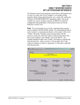
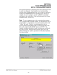
1
SECTION 2
INSTALLATION
________________________________________________________________________________
2.11.3 SYSdev PROGRAM DEVELOPMENT SOFTWARE INSTALLATION
The SYSdev Program Development software is used to perform on-line trouble-shooting and
program modifications to the HSL-RT6-M45. If SYSdev was purchased with the HSL-RT6-M45
package and is not already installed on the your computer, install SYSdev onto the hard drive of
your computer following the steps of the SYSdev Program Development manual.
________________________________________________________________________________
2.11.4 APPLICATION PROGRAM INSTALLATION
The HSLRT6 application program is a SYSdev based program loaded into the M4530 module and
performs the HSL-RT6-M45 logic. The HSLRT6 program is written in a combination of Ladder
logic and High-level. If the user desires to make program changes or perform on-line monitoring of
the program execution, the files which constitute the HSLRT6 program will have to be loaded onto
the hard drive of the PC which is used to support the HSL-RT6. The SYSdev Program Development
Software will also have to be loaded on the PC. To install this program perform the following:
1) Install the disk labeled “HSL-RT6-M45 PROGRAMS” into the drive.
2) For each of the “ HSLRT6” directories (created in section 2.11.2), copy all the files from the
disk to each of these subdirectories.
________________________________________________________________________________
2.12 TUNING THE HSL-RT6-M45
The HSL-RT6-M45 is shipped from the factory with the PLC program “HSLRT6” loaded in the
M4530 module (PLC section). This is the standard program used to implement the standard HSLRT6-M45 light tester algorithms.
Once the HSL-RT6-M45 is installed and the control system is powered back up, perform the
following to set-up and tune the HSL-RT6-M45. The set-up is performed using a PC running the
“HSLRT6” set-up program or the optional Keypad/Display. See sections 5 or 6 for a description of
the “HSLRT6” menus and variables and how to use the “HSLRT6” program. See section 4 for a
description of the Keypad commands and menu displays of the HSL-RT6 Keypad/Display.
At the initial installation, prior to performing the set-up steps below, verify that the default user
variables (see section 2.12.1) are set to the values listed.
HSL-RT6-M45 User’s Manual
SYSTEMS Electronics Group
- 17 -
SECTION 2
INSTALLATION
________________________________________________________________________________
2.12.1 DEFAULT SET-UP VARIABLES
As shipped, the user variables of the PMT section of the M4530 are set to the following defaults:
PMT Gain (PMT Voltage 0-1200V)
Gain Calibrate PMT Input Average
M4530 PMT Input Sensitivity
PMT Input Offset (-75 to 75)
PMT Reject Can Threshold
Automatic Offset Mode:
Enabled (Y/N)
Desired Good Can PMT Value
Allowed Good Can Error
PMT Gain Calibration Mode:
Enabled (Y/N)
Desired Calibrated Leaker Reject PMT value
Allowed Calibrated Leaker Reject Error
: 1101
: XXX
:7
: 000
: 075
: YES
: 030
: 002
: YES
: 120
: 005
Where “XXX” of the “Gain Calibrate PMT Input Average” can be any number. This will change
when a calibrate cycle is performed.
________________________________________________________________________________
2.12.2 SET MACHINE ZERO
Unlike the original encoder, the resolver shaft is not mechanically adjusted, to zero the timing, but
instead is electronically adjusted in the PLS section. Position the machine with pocket #1 precisely
aligned with the PMT, this is the machine zero location. Set the resolver offset per section 4.11
(HSL-RT6 Keypad/Display). Refer to section 5 (Windows based setup program reference) or
section 6 (DOS based setup program reference) to set the resolver using the setup program.
Note: The M4530 PLS is automatically programmed with the Sync timing (CH00) and Marker
timing (CH01). No other PLS timing channel programming is required by the user. The Sync timing
goes “on” at the centerline of PMT tube to pocket alignment and goes “off” at the centerline in
between pockets.
HSL-RT6-M45 User’s Manual
SYSTEMS Electronics Group
- 18 -
SECTION 2
INSTALLATION
________________________________________________________________________________
2.12.3 VERIFY THE B2F-RFI PMT HOUSING OFFSET
The C634 A1H Preamp board inside the B2F/RFI housing contains an offset potentiometer, used to
null any offset of both the PMT and amplifier circuitry. If this inherent offset of the PMT and
amplifier is too great, this potentiometer may have to be adjusted to null the offset to zero. This is
done by running cans through the machine and verifying the value the PMT offset automatically
obtains. The PMT housing offset only needs to be set at the initial installation or any time the B2FRFI PMT housing is replaced. All other offset variations due to temperature, etc. are automatically
compensated for with the automatic offset adjustment feature of the M4530. This adjustment simply
makes sure the offset potentiometer of the PMT housing is not set outside the normal range of
operation. Verify the offset as follows:
1) Run the machine with cans at normal line speeds and verify that the offset is automatically
adjusted until the “PMT Input Average” is equal to the “Desired Good Can PMT Value” within
plus or minus 2. “Up Peak (Max)” and “Down Peak (Min)” should also be within plus or minus
5 of the “PMT Input Average”.
2) If the offset exceeds + or -250 in an attempt to set the “PMT Input Average” equal to the
“Desired Good Can PMT Value”, the MAINT LED on the M4530 will be illuminated. This
indicates that the PMT is detecting an excessive amount of light both when the cans are sampled
and at the in-between pocket measurement. Verify that the machine is timed properly per
section 2.12.2 and that no light leakage is occurring at any of the PMT seals (machine shutter to
light seal plate, PMT to light seal plate, or at the PMT housing itself).
3) If the offset is greater then +/-20, disconnect the +24VDC power that powers the PS2000N1
high voltage power supply and remove the top of the B2F/RFI housing (side that contains
connectors) and adjust the potentiometer on the A1H Preamp board (first board below
connectors). Turning the pot clockwise will decrease the offset, turning it counter clockwise will
increase the offset. One turn of the potentiometer changes the offset by about 40 to 50.
4) Re-install the top of the B2F/RFI housing, power up the +24VDC power supply that powers the
PMT section of the M4530 and the PS2000N1 power supply and perform step 1 again. Repeat
steps 1 thru 3 until the offset is less than +/-20 while the machine is running with good cans.
The closer the offset is to zero, the better.
HSL-RT6-M45 User’s Manual
SYSTEMS Electronics Group
- 19 -
SECTION 2
INSTALLATION
________________________________________________________________________________
2.12.4 CALIBRATE THE PMT GAIN
Stop the machine, install a calibrated leaker in the machine at the PMT and perform the gain
calibration per section 3.4. If no calibration error occurred proceed to section 2.12.5.
If a calibration error did occur (“CAL” LED on front of M4530 “off” at completion of the
calibration procedure), observe the value of the PMT gain, either on the “M4530 Set-up” menu of
the “HSLRT6” set-up program or the “View PMT Data” menu of the HSL-RT6 Keypad/Display
and verify the following:
1) If the “PMT Gain” is less than 500 volts and the “Gain Calibrate PMT Input Average” is greater
than the “Desired Calibrated Leaker Reject PMT Value” by more than 5, the PMT detected too
much light and was not able to reduce the gain of the PMT adequately to compensate for the
amount of light detected. Verify that the calibrated leaker has a .0025 or less calibration hole in
it and does not have any other areas of light leakage in the can. Verify that the seal at the pocket
used for calibration is not leaking. Verify that no light leakage is occurring at any of the PMT
seals (machine shutter to light seal plate, PMT to light seal plate, or at the PMT housing itself).
2) If the “PMT Gain” is at 1101 volts and the “Gain Calibrate PMT Input Average” is less than the
“Desired Good Can PMT Value” by more than 5, then the PMT did not detect enough light and
was not able to increase the gain enough to calibrate the M4530. Verify that the calibrated
leaker has a .0025 calibration hole in it and also verify that the light source is generating an
adequate supply of light (lamps are “on” when calibration is performed). If so, set the “Desired
Calibrated Leaker Reject PMT Value” to a lower value (it can be set as low as 10 above the
“Desired Good Can PMT Value”) and try the calibration again. If the “Desired Calibrated
Leaker Reject Value” is lowered, the “PMT Reject Can Threshold” should also be lowered (it
should be between the “Desired Good Can PMT Value” and the “Desired Calibrated Leaker
Reject Value”).
HSL-RT6-M45 User’s Manual
SYSTEMS Electronics Group
- 20 -
SECTION 2
INSTALLATION
________________________________________________________________________________
2.12.5 VERIFY CALIBRATED LEAKER REJECTION
Run the machine at normal production speeds and verify that calibrated leakers, when run through
the machine, are rejected. Using the “HSLRT6” set-up program, observe both the Good Can Data
and the Rejected Can Data. The “PMT Input Average” should be within plus or minus 2 of the
“Desired Good Can PMT Value” set in the “M4530 Set-up Menu” (normally set to 30). The “Up
Peak (Max)” and “Down Peak (Min)” should be within plus or minus 5 of the “PMT Input
Average”. As leaker cans are rejected, they will appear in the “Last Reject Value” through “8th to
Last Reject Value” stack. When the calibrated leakers are run through the machine, the reject values
of these cans will also appear in this stack.
If any of the calibrated leakers are not rejected when run through the machine, lower the “PMT
Reject Can Threshold” and try again. This value can be lowered to within 5 above the “Desired
Good Can PMT Value”. If some of the calibrated leakers still are not rejected, increase the “PMT
Gain” (this can be increased to a maximum of 1200 volts) and try again.
Note: Running the gain of the PMT above 1100 volts will shorten the life of the PMT. If some of
the calibrated leakers are still not rejected, verify that the quality of light is adequate (both halogen
lamps are “on” and hub of starwheel is polished).
If the machine seems to be rejecting an excessive amount of cans, select the “4: View Can/Reject
Counts” selection from the Main Menu of the “HSLRT6” set-up program or the “Rejects Per
Pocket” selection of the HSL-RT6-DSP display and observe the Per Pocket Reject Totals. If a
particular pocket is rejecting a significantly higher number of cans than the other pockets, then that
pocket most likely has a bad light seal (or some other mechanical problem). In general, this menu
can be used to evaluate the reject performance of the machine.
HSL-RT6-M45 User’s Manual
SYSTEMS Electronics Group
- 21 -