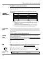
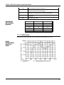
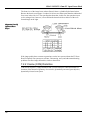
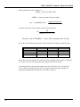
1
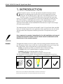
M2 / M2T 9.5 mm Reference Manual Open Frame Head with 6U EDD Style Drivers 60 FORDHAM ROAD WILMINGTON, MA 01887 TM GMAX SYSTEMS MULTI-AXIS BEAM HANDLING P/N 176-20027 Rev. E GSI Lumonics 1996 GMAX M2/M2T 9.5mm XY Open Frame Head TABLE OF CONTENTS 1. INTRODUCTION ...................................................................................................... 1 1.1 Warranty............................................................................................................................ 2 1.2 Customer Support ............................................................................................................. 3 1.3 Unpacking ......................................................................................................................... 3 2. GENERAL DESCRIPTION ....................................................................................... 5 2.1 Scan Head Types .............................................................................................................. 5 2.2 Mirror Types ...................................................................................................................... 6 2.3 Controller Types ................................................................................................................ 6 3. SAFETY AND WARNINGS ...................................................................................... 7 3.1 Laser Shutter Installation................................................................................................... 9 3.2 Installation Safety Requirements ..................................................................................... 10 4. OPERATION........................................................................................................... 11 4.1 Installation ....................................................................................................................... 11 4.2 Operating Instructions .....................................................................................................11 4.2.1 Driver Card Description..................................................................................... 12 4.2.1.1 Features ............................................................................................. 12 4.2.1.2 Power Requirements .......................................................................... 12 4.2.1.3 The SIC Backplane Card.................................................................... 12 4.2.1.4 Scanner Cable.................................................................................... 12 4.2.1.5 Front Panel Indicators ........................................................................ 12 4.2.1.6 Address Selection............................................................................... 12 4.2.1.7 Diagnostic Connector ......................................................................... 13 4.2.1.8 Setting for External or DAC Input ....................................................... 13 4.2.1.9 Traditional Temperature Controller ..................................................... 13 4.2.2 Scan Head Description ..................................................................................... 13 4.2.2.1 Scanner .............................................................................................. 14 4.2.2.2 Mirrors ................................................................................................ 14 4.2.2.3 Scan Angle ......................................................................................... 14 4.2.2.4 Outline and Mounting ......................................................................... 14 4.2.2.5 Thermal Behavior -- Maximum Allowable Temperature ...................... 14 4.2.2.6 Current Cutoff Circuit.......................................................................... 15 4.2.2.7 Dynamic Heating by Coils................................................................... 16 4.2.3 System Performance Data (Dynamics) ............................................................. 16 5. OPERATING ENVIRONMENT ............................................................................... 17 i GMAX M2/M2T 9.5mm XY Open Frame Head 6. HANDLING / MAINTENANCE ................................................................................ 19 6.1 Mirror Cleaning................................................................................................................ 19 7. APPENDIX A .......................................................................................................... 21 7.1 Mirror Selection Guide..................................................................................................... 21 7.1.1 Aperture Considerations ................................................................................... 21 7.1.2 Types of Mirrors................................................................................................ 22 7.1.3 Use in XY Scan Heads ..................................................................................... 23 7.1.4 Accuracy........................................................................................................... 23 7.1.5 Mirror Flatness Standards................................................................................. 24 7.1.6 Scratch and Dig Specifications ......................................................................... 24 7.1.7 Reflectivity ........................................................................................................ 25 7.1.8 Special Example -- Computing Power Capability of CO2 and YAG Mirrors ....... 26 7.2 Image Distortions ............................................................................................................ 27 7.2.1 OPD Distortion.................................................................................................. 27 7.2.2 Cosine (COS) Distortion ................................................................................... 28 7.2.2.1 COS Image Distortion ........................................................................ 29 7.2.2.2 COS Focus Distortion......................................................................... 30 7.3 Drive Signals ................................................................................................................... 31 7.3.1 Step .................................................................................................................. 31 7.3.2 Vector ............................................................................................................... 32 7.3.3 Raster............................................................................................................... 33 7.4 XY Calculations............................................................................................................... 35 7.5 Linearity Distortions......................................................................................................... 37 8. APPENDIX B .......................................................................................................... 41 8.1 Outline Drawings / Data Sheets ...................................................................................... 41 ii GMAX M2/M2T 9.5mm XY Open Frame Head 1. INTRODUCTION SI Lumonics 2-mirror, 2-axis XY galvanometer based Scan Heads provide the capability of deflecting optical beams in laser and vision applications. In laser writing, the XY Scan Head requires a light source focused through the XY Scan Head onto a target. The XY Scan Head then directs the focused spot to generate raster or vector patterns as programmed. For vision, these Scan Heads are used with CCD and Vidicon cameras, or with single-point detectors such as photomultipliers. Like the human eye, the XY Scan Head directs the image path to view different target areas. Typically, the Scan Head executes RANDOM ACCESS motions to acquire various images for vision system evaluation. G This manual describes GSI Lumonics M2 and M2T 9.5mm XY Open Frame Head with EDD drivers. It is ideally designed for vector applications. Raster applications are also well suited with this product when temperature monitoring and control is incorporated in the system design. As a component in a system, instructions for the safe installation and usage of systems that use GSI Lumonics XY Scan Heads should be obtained from the manufacturer of the complete product. WARNING Conventions Throughout the manual you will see graphic icons representing pertinent information in the text. The purpose of these icons is to provide a visual convention to alert you of a stop in the flow of the manual, where an important note or safety hazard alert is posted. NOTE is an important procedure you should be aware of before proceeding. CAUTION alerts you of a potential danger to equipment or the user. WARNING indicates an imminent danger to the user. TIP and REMINDER are helpful hints to procedures listed in the text. The conventions are listed as follows, showing both the text and the picture you will see. NOTE CAUTION TIP WARNING REMINDER GMAX, HC/2, HCI, PC-MARK MT, HPM and HPLK are trademarks of GSI Lumonics. Microsoft, MS-DOS and Windows are registered trademarks of Microsoft Corporation. 1 GMAX M2/M2T 9.5mm XY Open Frame Head 1.1 Warranty GSI Lumonics warrants this product to be free from defects in materials and workmanship for 12 months from the date of shipment. GSLI will, at its option, repair or replace the product if it is defective within the warranty period and returned, freight pre-paid, to a service center designated by GSLI. GSI Lumonics requests that customers obtain a Return Authorization Number prior to returning units, and that they carefully pack units in their original packing or equivalent. Under warranty, GSLI is not obligated to repair damage to any units resulting from the following conditions (customers are responsible for defining which conditions are applicable to their product): a) Personnel other than GSLI representatives attempting to repair or service the product. b) Improper use of the equipment. c) Connecting the product to incompatible equipment. d) Personnel other than GSLI representatives modifying the product. e) Scratches and chips on any optical surface after three weeks from the date of receipt. f) Damage to any optical surface from improper handling or cleaning procedures. This applies specifically to those items subjected to excess laser radiation, contaminated environments, extreme temperature or abrasive cleaning. Customers assume all responsibility for maintaining a laser-safe working environment. OEM customers must assume all responsibility for CDRH (Center for Devices and Radiological Health) certification. NOTE 2 There is no implied warranty of fitness for a particular purpose, and GSLI is not responsible for consequential damages. Individual components manufactured by GSLI or others may be covered by their own warranties. Refer to the appropriate manuals for this information. GMAX M2/M2T 9.5mm XY Open Frame Head 1.2 Customer Support GSI Lumonics has support services available to you concerning problems with either the product or manual you are using. Before calling for assistance, please make sure you refer to any appropriate sections in the manual that may answer your questions. The “Outline Drawings / Data Sheets” in Appendix B may be particularly helpful. If you need further assistance: The customer service personnel will be able to give you direct assistance and answers to your questions. U.S. (Massachusetts): (978)-661-4300 (in the U. S.) +01-978-661-4300 (outside the U. S) CALL Germany (Munich): +49 89 899134-0 Italy (Monza): +39 39 2025387 UK (Banbury): +44 132-787-2424 Japan (Tokyo): +81 3 3406 7990 ... ask for the GMAX Customer Service Department 1.3 Unpacking The package you receive will include those items mentioned in the packing list is included in the shipment that details the exact items shipped. a) CAREFULLY unpack the contents from the box. b) Save shipping container and packaging material in case you need to return unit for service. c) Check contents of the box against the packing list to assure all parts have been received. d) Inspect each item to assure it is not damaged. 3 GMAX M2/M2T 9.5mm XY Open Frame Head 2. GENERAL DESCRIPTION Enclosed with this package are the following: ITEM QTY 6U EDD Style Driver card 2 (tuned for XY) XY Head w/ XY mirrors 1 Each Scan Head is unique in the servo parameters it requires for optimum operation. Therefore, each XY Scan Head must be used with its calibrated driver. See Section “Operation” on page 11 for information regarding system set up. 2.1 Scan Head Types Scan Head Types with Part Numbers SCANNER APERTURE MIRROR PART #S M2 w/EDDs; no enclosure (OEM) 9.5 mm UV E00-7010530 “ “ Ag E00-7010543 “ “ Ar E00-7010019 “ “ Ar (high power) E00-7010020 “ “ YAG E00-7010017 “ “ CO2 E00-7010018 M2Tw/EDDs; w/Baseplate (OEM) 9.5 mm UV 000-3010527 M2Tw/EDDs; (OEM) “ UV 000-3010528 5 GMAX M2/M2T 9.5mm XY Open Frame Head 2.2 Mirror Types LASER TYPE YAG CO2 ARGON ARGON (HP) UV VISIBLE 9.5 9.5 9.5 9.5 9.5 9.5 Wavelength 1,064 nm 10,600 nm 488-514 nm 488-514 nm 325-360 nm 450-700 nm Coating Dielectric Dielectric on Metal Dielectric Dielectric Dielectric Durable Ag Reflection (min.) @ Wavelength (nm) 99.5% @ 1,064 99.5% 98.0% @ 480-514 99.5% 98.0% @ 325-350 96.0% Aperture (mm) 80.0% @ 450-650 50.0% @ 633 95.0% @ 350-360 45.0% @ 633 Flatness @ 633 nm λ/4 λ/4 λ/4 λ/4 λ/4 λ/4 Power Capability, cw (W/cm²) 500 500 100 5 MW/cm² 50 10 Power Capability, 100 ns pulsed (MW/cm²) 100 400 80 2 GW/cm² (10 ns pulsed) 40/20 40/20 60/40 40/20 40/20 40/20 Surface Quality (Scratch/Dig) See your GSI Lumonics sales representative for more details. 2.3 Controller Types The EDD cards are designed for use in a number of different DSC scan controller configurations. These include use with advanced GMAX software through interface connections to GSI Lumonics PC based HelperCard series (DSC with HCI card) and the traditional Digital Scanning Controller (DSC with DIC card). The DSC3000 nomenclature references a full 19“ width 6U high rack. Controller Types with Part Numbers 6 CONTROLLER PART #S DSC2000/M (HCI; no EDDs) E00-7017512 DSC2000/M (DIC; no EDDs) E00-7017014 DSC3000/M (HCI; no EDDs) E10-178191 DSC3000/M (HCI & LT EDD only) E00-7017525 DSC3000/M (HCI & LT EDD only; PostGrid Softw.) E10-155141 DSC3000/M (DIC & LT EDD only) E00-7017507 DSC3000/M (DIC; no EDDs) E00-7017517 GMAX M2/M2T 9.5mm XY Open Frame Head 3. SAFETY AND WARNINGS T he United States Food and Drug Administration, through the Center for Devices and Radiological Health (CDRH), has promulgated regulations (21 CFR parts 1000 and 1040) controlling the safety of lasers and laser products for sale or manufacture in the United States. GSI Lumonics XY Scan Heads are regulated by the CDRH. This section is a guide to the specific areas of this product and to the manual(s). Pay particular attention to CDRH compliance information. User Responsibili Responsibilities GSI Lumonics XY Scan Head are designed to provide maximum flexibility and ease of use. Such a design inherently requires the user to assure the overall safety of the configuration in use. It is the user's responsibility to insure that: 1) Only lasers certified to comply to CDRH regulations are used with GSI Lumonics XY Scan Heads. 2) Certified lasers contain features to assist in their safe usage. These protective features and the protective features within the GSI Lumonics XY Scan Heads should not be defeated. CAUTION Laser Hazard Analysis Prior to operating any configuration of the GSI Lumonics XY Scan Heads, you must make a through analysis of system safety. Key information for this purpose is contained in this manual. You would thoroughly familiarize yourself with all this information before proceeding. A full description of laser hazard analysis is beyond the scope of this manual. A good technical survey of laser safety requirements can be found in ANSI Z136.1, “American National Standard For the Safe Use of Lasers”. This is available from: American National Standards Institute, Inc. 1430 Broadway New York, New York 10018 Among the many other sources of laser safety information, the following institution offers several excellent publications.: The Laser Institute of America 5151 Monroe Street, Suite 118W Toledo, Ohio 43623 Final analysis of all safety features should be made by your Laser Safety Officer or a competent specialist in this field. The first consideration in a safety analysis is the laser mated to the GSI Lumonics XY Scan Head. The hazard level of the laser is roughly indicated by the Laser Class label that is on the device. A brief description of the radiation classes are shown in the following table. Note that, besides radiation, lasers may present other hazards, e.g.; electric shock or creation of poisonous fumes. 7 GMAX M2/M2T 9.5mm XY Open Frame Head Classes and Characteristics of Lasers LASER CLASS DESCRIPTION Class I Lasers are not considered to be hazardous. Class IIa Lasers are hazardous if viewed for periods greater than one thousand seconds. Class II Lasers are chronic viewing hazards. Class IIIa Lasers may represent acute, intrabeam viewing or chronic or acute viewing hazards when viewed with optical instruments. Class IIIb Lasers are an acute hazard to skin and eyes from direct radiation. Class IV Lasers are an acute hazard to skin and eyes from direct or scattered radiation. Do not use equipment outside of these ranges, as additional hazards may result. CAUTION Because we do not determine the laser used with our product, all GSI Lumonics end-user XY Scan Heads are labeled at the highest hazard level (Class IV). You should obtain information on output power or energy, wavelength(s) of output, duration of pulse, beam size and beam divergence from the manufacturer of the laser you are using. The wavelength and power of the laser actually used should be written on the warning logo type label, Position 2. (See Section page 33699 and 33700 of the Federal Register, Appendix B). Be sure to use a permanent, indelible ink. Class IV Warn Warning Label REMINDER 8 The Federal Register Rules and Regulations, Vol. 50, No. 161, dated Tuesday, August 20, 1985, contains the performance standards adopted by the Food and Drug Administration (FDA) which gives detailed information regarding the determination of laser classification and labeling. The ANSI and the FDA classifications are not the same. For purposes of labeling, use only the FDA classifications. If your laser falls in a classification below Class 4, replace the warning label type with the correct label and appropriate classification. The factory provides alternate labels upon request. The GSI Lumonics XY Scan Heads provide you with the ability to aim the laser beam over a roughly pyramidal volume. The divergence of the focused beam beyond the focal point, which is a function of the lenses selected and their position, can cause radiation to exit the pyramid. When analyzing safety, you must consider all regions within this aiming pyramid, the divergent beam, and the effects of all focal possibilities in the zone of hazard. Reflections must also be considered. GMAX M2/M2T 9.5mm XY Open Frame Head 3.1 Laser Shutter Installation The laser attenuator (shutter) is not included with the XY Scan Head. Because each laser is unique, it is the user's responsibility to insure that such a device is incorporated in the installation in conformance with CFR regulations (1040.10[f][6]), which reads as follows: REMINDER A beam attenuator is required on Class II, IIIa, IIIb and IV laser systems. The beam attenuator is a mechanical or electrical device such as a shutter or attenuator that blocks emission. The beam attenuator blocks bodily access to laser radiation above Class I limits without the need to turn off the laser. The beam attenuator must be available for use at all times during operation. Power switches and key controls do not satisfy the attenuator requirement. Example of Laser Shutter Location in a HPLK System The beam shutter should be installed between the laser head and the Scan Head. The following figure shows the recommended location of the shutter. NOTE Laser Scanner Ha Hazard zard Zones of an HPM Scan Head We strongly recommend that you specify a laser with a vendor-supplied shutter mechanism. If this is not possible, consult the laser vendor to design a proper safety shutter. The figure shows the laser's internal and external optical path towards the target plane, specifically where the hazard zones are located as the optical beam passes through as HPM Scan Head 9 GMAX M2/M2T 9.5mm XY Open Frame Head 3.2 Installation Safety Requirements Because of the possible hazard increase of scanning stopping or slowing to an unsafe velocity, it is required that the controller software shuts down the laser power (a scanning safeguard). In all cases, we recommend that you fully enclose and interlock the zone of hazard for your application to prevent possible opening while the laser is energized. When laser radiation exceeding Class 1 levels may exit the enclosure, you must have suitable protection for eyes available. NOTE At no time should you stare into the beam, place any parts of your body in the beam path, or expose yourself to reflections of powerful beams. You should use only a Class 1 HeNe Laser for alignment. If this is not possible, you should use the available laser's lowest power setting and remote beam sensing technique. Using optical instruments with this product increases eye hazard. CAUTION Additional Safety requirements may be applicable during initial alignment of the optical system. Refer to Section, “Safety and Warnings”, Section 3. GSI Lumonics XY Scan Heads are labeled in conformance to the requirements of 21 CFR parts 1000 and 1040. 10 GMAX M2/M2T 9.5mm XY Open Frame Head 4. OPERATION Use of controls or adjustments or performance of procedures other than those specified herein may result in hazardous radiation exposure! CAUTION 4.1 Installation Installation of the XY Scan Head is relatively simple. Four holes that will accept 1/4" screws have been provided in the baseplate. Additionally, two dowel pins have been placed in the baseplate, allowing repeatable alignment of the XY Scan Head to it's mounting surface. Refer to outline drawings in the appendix for exact locations of these features. After securely mounting the XY Scan Head, connect the drive cables provided to the X and Y servos. If you have purchased GSI Lumonics controllers, the X and Y servo drivers are clearly identified on the front panel. Be careful to connect the X servo on the XY Head to the driver card labeled X servo and the Y servo on the XY Head to the driver card labeled Y servo. Tighten screws to capture the connectors. 4.2 Operating Instructions GSI Lumonics XY Scan Heads have been designed to provide optimal performance when driven with a number of different scan controllers. The EDD cards are designed for use in a number of different scan controllers. These include use with advanced GMAX software through interface connections to GSI Lumonics PC based HelperCard series (DSC with HCI card) and the traditional Digital Scanning Controller (DSC with DIC card). The DSC3000 nomenclature references a full 19“ width 6U high rack. DSC Types with Part Numbers CONTROLLER PART #S DSC2000/M (HCI; no EDDs) E00-7017512 DSC2000/M (DIC; no EDDs) E00-7017014 DSC3000/M (DIC & LT EDD only) E00-7017507 DSC3000/M (DIC; no EDDs) E00-7017517 The controller user manual provides all necessary information for the safe operation of the XY Scan Head. 11 GMAX M2/M2T 9.5mm XY Open Frame Head 4.2.1 Driver Card Description 4.2.1.1 Features The driver card is configured specifically for use with M class scanners with sum-dif (∑ ∆ ) detector configurations. In many ways it is identical to the M3H driver. Pertinent Features Include Feature Σ∆ M3 output stage double push pull double push pull detector input voltage mode sum dif derived AGC servo feedback controls vel, err, int, pos vel, err, int, pos input filters none slew rate limiter scanner protection fuse fuse and temperature estimation mechanical 6U Euro (DIN) std 6U Euro (DIN) std backplane M3H type M3H type 4.2.1.2 Power Requirements The analog section and scanner power amp requires ±18V @ 1A continuous and 5A peak. The digital portion requires 5V @ 1A max. 4.2.1.3 The SIC Backplane Card Each driver must interface through the “Scanner Interface”. This is identified by the dual connectors for the galvo cable. It is the same used for the M3H. 4.2.1.4 Scanner Cable To connect the scanner to the SIC backplane use the same cable used with the M3H. Note that the M2 called for has a 15 pin connector. 4.2.1.5 Front Panel Indicators Three green indicators signal status of the scanner-driver: • In Field when lit indicates the galvo is operating within its rated angle. • Tracking when lit indicates the difference between command and position (error) is lower than a preset limit. Blinking may be normal in applications with high slew rate commands. • Power when lit confirms that ±18 and +5 V supplies are operating. 4.2.1.6 Address Selection W5 is configured to set the strobe select address and status signal read back. W5 is found on the PCB in the exposed section towards the DIN connectors. Configure the jumpers connecting as the shaded segments show in the following chart(s). 12 GMAX M2/M2T 9.5mm XY Open Frame Head W5 Jumper Settings, "X" W5 Jumper Settings, "Y" 2 4 6 8 10 12 14 16 18 1 3 5 7 9 11 13 15 17 2 4 6 8 10 12 14 16 18 1 3 5 7 9 11 13 15 17 Resulting Outputs on I/O Bus ADDRESS LINES A4 A3 A2 A1 SELECT MODULE 1 X 0 1 Y servo 1 X 1 1 X servo 4.2.1.7 Diagnostic Connector The following signals are available on the diagnostic connector.(located on SIC backplane) Diagnostic Connector SIGNAL PIN SIGNAL PIN AGC Volts 1* 2 scanner I @ 1V/Amp DAC out w/slew rate 3 4 signal ground position out 5 6 external POS in ±5V 10X POS Err out 7 8 velocity out NC 9 10 NC *key 4.2.1.8 Setting for External or DAC Input The board can be configured for either DAC or Analog input thought the diagnostic connector. Only the DAC analog passes thought the slew rate limit circuit. Analog inputs will not be slew rate limited. NOTE To make the selection remove the front panel via six Phillips head screws. Locate segments 5 and 6 labeled DAC ENBL and EXT ENBL. Left-left (close-close) enables DAC input and disables external input. Right-Right enables external input. 4.2.1.9 Traditional Temperature Controller This driver includes a traditional temperature controller which is wired to the backplane. The M2 does not use this capability. NOTE 4.2.2 Scan Head Description 13 GMAX M2/M2T 9.5mm XY Open Frame Head 4.2.2.1 Scanner M2 with 15 pin connector. See the data sheet in Section “Outline Drawings / Data Sheets”, Appendix B. 4.2.2.2 Mirrors 9.5 mm clear aperture. See options in Section “Mirror Types” on page 5. 4.2.2.3 Scan Angle ±21 optical (clear aperture), calibrated for ±20 (±0.5%). 4.2.2.4 Outline and Mounting See Section “Outline Drawings / Data Sheets”, Appendix B, for an outline drawing. 4.2.2.5 Thermal Behavior -- Maximum Allowable Temperature NOTE WARNING The following “Thermal Behavior” discussion is most important for raster applications. Vector applications typically require only 0.1 W to 1.0 W (0.2 °C rise) of applied power to the scanner. Failure to perform these measurements and calculations for raster applications may result in significant scanner damage caused by an overtemperature condition. The current cutoff circuitry in the driver electronics (described in Section “Current Cutoff Circuit” on page 15) will only protect the scanner if the scanner mount temperature is held below 48 °C. The scanner temperature is limited by a maximum allowable coil temperature of 100 °C. It is critical that the coil temperature does not exceed 100 °C for each application of this Scan Head. This coil temperature may be estimated by the method below. 1. Determine the pattern which has the highest RMS power. This power may be measured by connecting a true RMS meter to the “drive current” output of the diagnostic connector. This RMS current is then multiplied by the coil resistance at 100 °C (6.05 ohms) to determine power. Do not apply this pattern for more than 5 seconds until the power has been calculated or damage may result. 2. Next, measure the maximum scanner case temperature under conditions of maximum internal system ambient temperature and zero internal scanner power. 3. The preliminary coil temperature is calculated by adding the scanner temperature rise (power times 2.5 °C/W scanner thermal resistance) to the maximum scanner case temperature. 4. If the coil temperature calculated in (3.) above is acceptable, apply maximum scanner drive power and again measure the scanner case temperature. Recalculate the coil temperature. 14 GMAX M2/M2T 9.5mm XY Open Frame Head 4.2.2.6 Current Cutoff Circuit The circuit described below is sensitive to RMS current only and not coil temperature. It is essential that the user perform the above calculations to prevent malfunction or damage to the scanner. WARNING Should the current cutoff circuit cause the scanner to operate intermittently the user should cease operation immediately and review his input drive command. There is a current cutoff circuit on each driver board which calculates RMS current in the scanner coil and disconnects the driver when the current exceeds 1.7 amps RMS (square wave input) and 1.42 amps RMS (sine wave) steady state for 30 seconds. The power permitted at these currents must be calculated using the coil resistance at the galvo operating temperature. The power at room temperature (25 °C) is calculated using a coil resistance of 4.65 ohms. At 100 °C, the power is calculated using a coil resistance of 6.05 ohms. Since the circuit has a built in delay, the current may exceed these values for periods of time shorter than 30 seconds. For instance, the circuit will permit 2.13 amps (square wave) for 13 seconds. This circuit should prevent coil damage under most long-term over power situations, but does not eliminate the possibility of damage due to brief fault conditions involving significantly higher currents. In summary, this circuit will not prevent damage due to unusual fault conditions during tuning or system debug. 15 GMAX M2/M2T 9.5mm XY Open Frame Head 4.2.2.7 Dynamic Heating by Coils This is the standard open frame Scan Head with high conductance mounting rings installed between the scanners and bracket. These have a thermal impedance of approximately 0.6 °C /W. This, combined with the M2 coil impedance of 2.5 °C/W, can be used to calculate a max. average power capacity; for example: (100 °Ccoil max - 30 °Cframe ambient) / 2.5 °C/W = 25W NOTE Because the internal temperature of the scanner varies with coil heating some thermal drift will occur. A coefficient of approximately 100 PPM gain per °C of coil temperature can be anticipated. Heat Sinking Test Coil Rm RC Frame Q coil In the Scan Head supplied, heat sinking tests resulted in the following typical values: Rc = 2.5 °C/W Rm = 0.6 °C/W Rtotal = 3.1 °C/W 4.2.3 System Performance Data (Dynamics) System 16 Slew rate limiter setting 375 rad/sec Tracking offset 340E-6 rad*sec/rad 2)3) Spec. Velocity 10 rad/sec Spec. Velocity Settling 1.5 msec Tracking Linearity 300E-6 Rad 3) Step and settle (7 mrad) 1.5 msec (to 70E-6 Rad err) Notes: 1) 2) 3) All angles in optical radians. rad*sec/rad * rad/sec (vel) = position lag in radians. May be converted to volts by 10V/.698 rad. GMAX M2/M2T 9.5mm XY Open Frame Head 5. OPERATING ENVIRONMENT The following recommendations cover the handling, use or storage of Scan Heads. Environmental Requirements Storage Temperature: -10°C to +60°C Minimum Operation Temperature: +15°C Maximum Operating Temperature: +34°C Humidity: Non-condensing 17 GMAX M2/M2T 9.5mm XY Open Frame Head 6. HANDLING / MAINTENANCE T he GSI Lumonics XY Scan Head does not contain any user serviceable or user maintainable parts. However, you should visually inspect all optical surfaces each time lenses and alignment mirrors are handled. Make sure that the laser is off before performing any inspections! Wear finger cots or cotton gloves when handling optics for inspection. NOTE All contamination on optical surfaces must be remove prior to operation or serious damage and/or hazard may result. The Scan Head must be protected from airborne contaminates. Dust attaching through impact or heating and vapors condensing on the optical surfaces reduces the mirror's reflectivity. Furthermore, avoid scanner exposure to dust, condensation or cleaning fluids in the exposed bearing area. You must be extremely careful not to allow contamination from entering the galvanometer though it’s exposed bearing. Serious scanner damage may result. CAUTION If you feel that cleaning or service is necessary, contact the customer service group at General Scanning for information regarding service. 6.1 Mirror Cleaning Although the mirrors can be replaced by the user, we do not recommend you do so. Furthermore, GSI Lumonics does not recommend cleaning front surface mirrors. Mirrors damaged by cleaning are not included under the warranty. The surface of these mirrors damages easily. It is difficult to prevent hard dust particles from being entrained in the process and causing scratches. In many cases, small defects in the mirror's surface may less harmful than the surface damage resulting from continued cleaning. It requires special equipment typically not available to customers. There are times, however, when cleaning the mirror becomes a necessity, e.g. stains such as fingerprints must be removed immediately to prevent permanent etching of the reflective surface. The information below includes general recommendations for those special occasions when mirrors must be cleaned. Removing Dust Remove lint from mirrors with a jet of low pressure clean air. Blowing on front surface mirrors deposits moisture that may stain the finish. 19 GMAX M2/M2T 9.5mm XY Open Frame Head Removing Stains A thin overcoating of silicon monoxide protects most mirrors from oxidation. Like many optical coatings, it is easily damaged when attempts are made to clean the mirror surface with a dry tissue. The safest method of cleaning is to place a piece of lens tissue on the mirror surface and wet it with reagent grade (highly pure) alcohol or acetone (If you use acetone, take precautions regarding possible health and fire hazards). Grasp an overhanging corner of the tissue and gently agitate it several times, then slide the tissue off. This should remove the problem blemishes. Do not let solvent enter the bounding zone of the mirror. CAUTION Note that the mirror is not rubbed. NOTE If the mirror surface is still contaminated, use a highly pure solvent such as alcohol or acetone and generously wet the mirror surface with a sterile cotton swab or lens tissue. Gently wipe the dirty areas. Turn your cotton swab or tissue with each stroke so that a clean area is exposed. CAUTION 20 Do not let solvent enter the scanner bearings. When wetting the mirror's surface, hold the scanner at an angle so that the liquid does not wet the scanner. If any solvent is found in the bearings of the scanner, the warranty is voided. GMAX M2/M2T 9.5mm XY Open Frame Head 7. APPENDIX A 7.1 Mirror Selection Guide 7.1.1 Aperture Considerations Aperture The aperture of the Scan Head is the limiting opening through which the optical system must image. The most important trade-off to recognize when selecting a Scan Head is that larger apertures provide better optical properties but slower motion capability. A two-mirror, two-axis Scan Head has a number of distinct apertures. One or more of the apertures determine the pupil of the Scan Head in any given situation. These apertures are: EA: Entrance Aperture, or location where the Scan Head structure limits the size of a lens element. This is the usual location of the last imaging element. The EA defines the maximum allowable diameter of a lens and its housing. Xn: X mirror near aperture is sized and located by the near edge of the X mirror when rotated to its shallowest angle, typically 35 degrees mechanical. Xf: X mirror far aperture is similar to Xn, but it is sized and located at the far edge of the X mirror. Generally Xf does not come into play in computations. Yn: Y mirror near is the Y mirror counterpart of Xn. Yf: Y mirror far is the Y mirror counterpart of Xf. Unlike Xf, it will be important in certain vision computations. Xc: X mirror clip is the beam radius to the corner of the X mirror, viewed by the Y mirror. This occurs when the scanners are pointed to the extreme lower right-hand corner of the field. S: Distance from EA to the surface of the X mirror nearest the axis of rotation, in the center of rotation. Sxn and Syf are similarly located. E: Distance from (a) to the surface of the Y mirror nearest the axis of rotation, in the center of rotation (b). Positions of Apertures Typical Aperture Dimensions of Some XY Scan Heads (mm) XY Head EA S 5 mm 66.0 40.0 Sxn 3.6 Xn E 5.0 7.0 Syn 2.3 Yn 5.0 Sxc n/a Yf 5.0 Xc Lim Apert. ≥ 2.5 Xn 21 GMAX M2/M2T 9.5mm XY Open Frame Head 10 mm 30.0 28.4 7.1 10.0 13.0 5.5 10.0 n/a 10.0 ≥5 Xn 20 mm 38.1 25.2 14.3 20.0 26.0 11.3 20.0 n/1 20.0 ≥ 10 Xn 30 mm 50.8 28.4 21.4 30.0 37.0 14.4 27.7 20.3 26.1 11.7 Yn 50 mm 58.0 70.0 35.7 50.0 67.0 22.1 47.4 42.4 46.4 22.6 Yn 7.1.2 Types of Mirrors To optimize their performance, GSLI Scan Heads incorporate one or more of the mirror constructions described below. First Surface Mirrors First Surface Mirrors are designed with the reflective surface on the axis of rotation. This simplifies the computation of dynamic geometric correction (discussed in Section “XY Calculations” on page 35 ) Unfortunately, it also creates a lateral imbalance in the scanner when the mirror rotates. First surface mirrors are restricted to scanners carrying apertures either outboard supported, as in the 50 mm Scan Head, or structurally stiff enough, as in the 10 mm and 20 mm Scan Heads. Mass Balanced Mirrors Mass balanced mirrors position the mirror mass in a balanced configuration about the scanner's axis of rotation, thus eliminating lateral forced due to rotation. This allows less robust scanner structures to more easily support large aperture mirrors. This increases the sensitivity of the input beam to mechanical alignment errors and adds a small amount of X, Y and focus linearity error. For scan radii greater than a few hundred times the mirror offset, these errors become negligible. Type of Mirrors Typical Surface Offset Dimensions for XY Heads 22 MIRROR SIZE OFFSET 5 mm 0.5 mm 10 mm 1.5 mm 20 mm 1.5 mm 30 mm 2.0 mm GMAX M2/M2T 9.5mm XY Open Frame Head Inertially Matched Mirrors Inertially Matched Mirrors are designed with X and Y mirrors having nearly the same moment of inertia. This allows the scanners to be tuned to match each other and improves vector performance. The small reduction in Y aperture matches typical laser focus cones. A canting of the X axis also increases the Y incident angle. These serve to reduce Y inertia to match X. 7.1.3 Use in XY Scan Heads The three basic configurations of Scan Heads are: • STD 45 Degrees Heads These are the simplest to configure. Each mirror is designed to reflect the beam at a nominal incident angle of 45 degrees, therefore the Y axis is directly over the X axis. • Y Optimized Heads These rotate the X axis 5 to 15 degrees, reducing the required width of the Y mirror by a more normal angle of incidence. In some cases this allows the inertia of the Y mirror to be reduced to match the X. The disadvantage is the possibility of "X mirror clip" occurring. This may happen when the Scan Head is directed to the lower right corner of the field. The corner of the X mirror may clip the Y output beam. Where applicable this is specified in the aperture specifications as a clipping beam radius. • Outboard supported Scan Heads (XY5067 only) This Scan Head uses a specially designed outboard bearing and drive coupling to support the mirrors. It is implemented in cases where the bending inertia of mirror loads exceeds practical scanner limits. 7.1.4 Accuracy As a general rule the accuracy constraints of the Scan Heads in this manual are the following: • Accuracy The accuracy (derived from non-linearity in scanners) of the angular position at rest +/0.3% of full field. For a +/-20 degrees scan, the maximum error would be +/-7 min. arc, or +/-2 milli-radians in each axis. • Mirror Angles The mirror angles to the mounting references are within +/-10 milli-radians and within +/6 milli-radians to each other. • Mirror Axes The mirror axes are true position to the mounting references within +/-0.015 inches (+/-0.38mm). This is not a guaranteed specification for all configurations. If more stringent tolerances are needed, consult the factory for recommendations. NOTE 23 GMAX M2/M2T 9.5mm XY Open Frame Head 7.1.5 Mirror Flatness Standards For the optical system to perform the mirror surface must be of adequate flatness to prevent degradation of the image. The next table lists recommended minimum specifications for various pupils and applications. Typical Mirror Flatness for XY Heads APERTURE POWER (FRINGES) IRREG. (FRINGES) 5 mm 1/2 1/2 10 mm 1/2 1/2 20 mm 1/2 1/2 30 mm 1 1 50 mm 1 1/2 1 1/2 Notes: 1. Fringes are equal to 1/2 wave OPD (Optical Path Distortions) at 633 nm. For longer wavelengths the effect of OPD must be scaled inversely to the wavelength (refer Section “Image Distortions”, Section 7.2). 2. Power refers to the symmetrical, spherical distortion of the surface in fringes. Power degrades optical performance to a lesser degree than Irreg. 3. Irreg. refers to the non-symmetrical commonly cylindrical distortions of mirror surfaces. It is the key offender in the OPD deformities of out of round spots and astigmatism. Recognizing Flatness Problems Mirror non-flatness in imaging systems usually appears as astigmatism in the image. That is, vertical and horizontal axes do not focus optimally at the same plane. In focused laser spots, the spot is oval, and in vision images, the vertical and horizontal image features do not focus at the same planes. 7.1.6 Scratch and Dig Specifications Scratch/Dig A mirror is surface specified by a scratch/dig notation such as 40/20, 40 referring to the scratch and 20 to the dig number. Scratch A scratch is a gouge or tear in the mirrors reflective surface. The scratch number defines the sum of the scratch widths in micro-meters. That number must not be exceeded when all the scratches in the useful aperture are summed. The sum of the lengths of all the scratches in the useful aperture must not exceed 1/4 of the useful aperture diameter. Digs Digs are pits or gouges, more or less round in nature. When summed, all the "dig" diameters in the useful aperture must not exceed the dig number times 10 micro-meters. NOTE Common Scratch/Dig CallCall-outs 24 In the Y Mirror of many Scan Heads, the useful aperture is defined by a moveable ellipse of the size typical of the image beam on the mirror, not the full mirror for both scratch/dig and flatness. SCRATCH/DIG DESCRIPTION GMAX M2/M2T 9.5mm XY Open Frame Head Typical XY Head Mirror Scratch/Dig Specifications 10/5 Highest quality laser surface. Scatter free. 20/10 Laser quality. Used particularly with smaller apertures where scatter or interference patterns cannot be tolerated. 40/20 Very good optical quality. Beam splitters and laser photographic. The small defects have little effect on relatively large apertures. 60/40 General optical quality. Visual optics and general purpose laser photographic. 80/50 Good plate glass quality. APERTURE SCRATCH DIG 5 mm 20 10 10 mm 40 20 20 mm 60 40 30 mm 60 40 50 mm 80 60 7.1.7 Reflectivity Reflectivity is measured by the ratio of incident to reflected light at 45 ± 10°. Example: First Surface Mirrors Normal to 45° Incidence Legend: A: Protected aluminum C: Durable silver B: D: Enhanced aluminum (non stock, ref. only) First surface gold (non stock, ref. only) 25 GMAX M2/M2T 9.5mm XY Open Frame Head Example: Theoretical Reflectivities of Dielectric on Silver Coatings Legend: A: Polarization, 10.6 µm C: Polarization, 1.06 µm B: D: Polarization, 10.6 µm Polarization, 1.06 µm 7.1.8 Special Example -- Computing Power Capability of CO2 and YAG Mirrors The power capability of high power laser working mirrors can be computed. Assume the reflected beam is a TEM00 Gaussian beam. The table below gives peak irradiance capability. Compute the total power for a 2/3 filled aperture in Watts, given the peak irradiance (Ip), aperture (Ap), as follows: Watts = Ip • PI • Ap 2 18 This equation assumes that the 1/e2 diameter is 2/3 filling the aperture, which ensures that 99% of the power is transmitted. Should there be extra power, 86% transmission is acceptable. The full 1/e2 diameter may fill the mirror providing a beam stop aperture is supplied prior to the Scan Head. This ensures fringe energy does not overheat the mirror mounts and the surrounding scanners. Compute the total beam power for a filled aperture as follows: Ip • PI • Ap 2 Watts = 8 Any contamination on a high power mirror surface degrades its capability. Contamination must be considered when figuring power capability. CAUTION 26 GMAX M2/M2T 9.5mm XY Open Frame Head Safe Peak Irradiance Capability Laser Power Capability for Mirrors (2/3 Filled Aperture) Among the Variations to Consider WAVELENGTH CE PEAK IRRADIANCE PEAK PULSED IRRADIANCE 10.6 µm 500 W/cm2 400 MW/cm2 1.06 µm 100 W/cm2 80 MW/cm2 APERTURE 1.06 µM PULSE 1.06 µM CW 10.6 µM PULSE 10.6 µM CW 10 mm 14 MW 18 W 72 MW 87 W 20 mm 56 MW 70 W 280 MW 350 W 30 mm 125 MW 156 W 624 MW 780 W For the same reasons as CW lasers, pulsed laser power must be examined for peak irradiance of the pulse for damage threshold and also for average power. If the beam is multi-mode, estimate its peak irradiance from profiles supplied by manufacturers. 7.2 Image Distortions Two types of image distortions are of principal interest: 1. OPD (Optical Path Distortion) causes imaging distortions. These are dependent on mirror quality only. Scan angle does not affect the results. 2. Cosine distortion causes spot elongation for laser and compression of the image frame for vision. Both occur approaching the field edges. 7.2.1 OPD Distortion Optical Path Distortion may be caused by the Scan Head or imaging system. Path length variations for different portions of the beam may cause blurring in parts of the image. Focusing at an image plane before or after the primary image place also may result in distortion. Alternately, portions of the image beam may be directed to image at an incorrect position in the image plane. In focused laser systems, OPD frequently appears as elongated or distorted spots. These defects appear in different axes in the near and far focus about the optimum focus or as "lobes" of energy projecting from the focused spot. In vision systems, the image is not always diffraction limited, particularly with the larger apertures. As much as 1/2 or even 1 wave of distortion may produce acceptable results. Mirror non-flatness in imaging systems is a common cause of OPD and is likely to appear as astigmatism in the image. Vertical and horizontal axes do not focus optimally at the same plane. This is seen in the two views of the image beam in the figure shown on the next page. The incorrect imaging position of certain bundles of light typically reduces contrast in the image. 27 GMAX M2/M2T 9.5mm XY Open Frame Head The front view of the image beam, when reflected, forms a cylindrically deformed mirror. Because the beam's convergence is reduced, it focuses at a farther point than the undisturbed focus cone in the side view. The spot diagrams show that, in this case, the spot takes on an oval or enlarged size; however, it never attains the theoretical focus and size of the wellformed image on the right. Astigmatism Caused by Cylindrical Mirror Surface If the image quality does not meet expectations, test the lens system without the XY Scan Head. Frequently lens systems are to blame. Decentering, stress, and other manufacturing problems can cause image deformities similar to the mirrors. 7.2.2 Cosine (COS) Distortion COS has two aspects: 1) Image Distortion and 2) Focus Distortion. These distortions are functions of the theoretical geometry of a two-axis, dynamically-corrected, post-objective, dynamically-focused scan system. 28 GMAX M2/M2T 9.5mm XY Open Frame Head 7.2.2.1 COS Image Distortion Because the scanners point from a single point in a space on the target field, the incident angle varies with position. The following diagram depicts COS distortion for a vision system. The shape of the target images seen in the Scan Head pupil is shortened along the shadow axis to the dimension: H' = H ∗ COS (theta) COS Distortion in Vision And, of course, in a laser scanning configuration, the imaged spot lengthens by the same percentage. The elongation axis is along a line drawn from the center field to the coordinate acquired. The equation to compute the incident angle is: TAN 2 ∅ X + TAN 2 ∅ Y ∅ i = ATAN COS 2 ∅ Y 1/ 2 The table following shows the distribution of cosine distortion over one quadrant of a typical scan field. Note that this distortion is only dependent on the X and Y scan angles. By computing the X and Y scanner angles for a field coordinate of a proposed field, you can look up the cosine distortion. 29 GMAX M2/M2T 9.5mm XY Open Frame Head Distortion of Cosine Cosine Distortion in First Quadrant % Cosine Distortion (as % of image size) (deg) Y 20 6.8 6.8 7.0 7.3 7.7 8.2 8.8 9.5 10.4 11.3 12.4 18 5.4 5.5 5.6 5.9 6.3 6.8 7.5 8.2 9.1 10.0 11.1 16 4.2 4.3 4.4 4.7 5.1 5.7 6.3 7.0 7.9 8.8 10.0 14 3.2 3.2 3.4 3.7 4.1 4.6 5.3 6.0 6.9 7.9 9.0 12 2.3 2.4 2.5 2.8 3.2 3.8 4.4 5.2 6.1 7.1 8.2 10 1.6 1.6 1.8 2.1 2.5 3.1 3.7 4.5 5.4 6.4 7.5 8 1.0 1.1 1.2 1.5 2.0 2.5 3.2 4.0 4.9 5.9 7.0 6 0.6 0.6 0.8 1.1 1.5 2.1 2.7 3.5 4.4 5.4 6.6 4 0.2 0.3 0.5 0.8 1.2 1.8 2.4 3.2 4.1 5.2 6.3 2 0.1 0.1 0.3 0.6 1.0 1.6 2.3 3.0 4.0 5.0 6.1 0 0.0 0.1 0.2 0.6 1.0 1.5 2.2 3.0 3.9 4.9 6.1 (deg) X 0 2 4 6 8 10 12 14 16 18 20 7.2.2.2 COS Focus Distortion When the image beam is incident on the target field at an angle as shown in the figure below, the path length to diagonal corners of the field varies as the angel theta calculated previously. COS Focus Distortion The next table shows the distribution of COS focus error in terms of the +/- focus depth required, expressed as a % of frame size (not to be confused with the field size). 30 GMAX M2/M2T 9.5mm XY Open Frame Head Distribution of COS Focus Error (as % of Image Size) (deg) Y 20 18 18 18 19 19 20 21 21 22 23 24 18 16 16 17 17 17 18 19 20 21 22 23 16 14 14 15 15 16 17 17 18 19 21 22 14 12 13 13 13 14 15 16 17 18 19 21 12 11 11 11 12 13 14 15 16 17 18 20 10 9 9 9 10 11 12 14 15 16 18 19 8 7 7 8 9 10 11 12 14 15 17 18 6 5 6 6 7 9 10 12 13 15 16 18 4 4 4 5 6 8 9 11 13 14 16 17 2 2 2 4 6 7 9 11 12 14 16 17 0 0 2 3 5 7 9 10 12 14 15 17 (deg) X 0 2 4 6 8 10 12 14 16 18 20 For example, at the angle X=20°,Y=20° the variation in focus range is +/-24% of the frame size. A 0.25" square frame at corner field extreme has a field diagonal of 0.35" and thus requires 0.35 x 0.24 = +/- 0.08" depth of focus or blur would occur at the frame corners. In most cases, large frame imaging prevents this problem by avoiding the extreme angles. Using small F numbers also alleviates the blur. Lasers, of course, have small image sizes and COS focus distortion is frequently ignored. 7.3 Drive Signals Drive Signals (Step, Vector, Raster)The mechanical Scan Head design requirements vary depending on the criteria for optimal performance. Specifically, each of the three motions STEP, VECTOR, or RASTER - has different performance definitions and requirements. 7.3.1 Step Step motion occurs when the scanners rotate directly to a new position. This new position may be randomly located anywhere in the scanner's legal operating angle. The performance parameters of Step motion are: • Phase Delay The dwell after the input of a signal, before 1/% of the scanner motion occurs. • Motion The period during which 99% of the scanner motion is executed. • Settling After 99% of the motion is completed, the scanners settle and correct for any small position errors that might exist. • Error The +/- deviation from the programmed scan angle. 31 GMAX M2/M2T 9.5mm XY Open Frame Head Step Motion Step operation requires the longest settling time due to the saturation effects of the amplifier and variations in scanner parameters. These allow for optimized tuning over small range of angles only. Use over the full range requires greater settling time. Vector type slewing is the preferred way to obtain point-to-point motion. It is likely to be just as fast for large steps and faster for small ones. 7.3.2 Vector A Vector is created by the coordinated rotation of one or both axes of an XY Scan Head. Two types of vectors may be drawn: • Point-to-Point Vectors begin and end at drawn line endpoints. In most cases this is the fastest pointto-point transit. • Skywriting The scanners back up, then scan across the start point and across the end point, stopping beyond the end point. Although this type vector solves acceleration and deceleration exposure problems, it may not be faster than point-to-point. This is because the acceleration and deceleration lengths take significant time, and the ultimate drawing speed is limited by Tracking Linearity, the same as point-to-point. There are two key aspects to accurate vectors: 1. The synchronization of the axes is a function of Scan Head design and servo tuning. 2. The control of the vector velocity on the target field. The evaluation parameters of Vector scanning are: • Vector Rate The angular velocity of the "drawn" line or optical scan angle. • Phase Delay a) The time at the beginning of the vector after the ramp has begun, before the scanners have moved. b) The period after the ramp has ended and the scanners continue at constant velocity toward the ending coordinate • Acceleration Length The length of line "drawn" while the scanners are accelerating to full velocity. 32 GMAX M2/M2T 9.5mm XY Open Frame Head • Tracking Offset The steady state error between input signal position and actual position during the vector motion. • Tracking Linearity The +/- deviations in tracking offset from the average offset of X and Y during the vector motion. • Acceleration Error At the start of each vector the two axes must accelerate identically to produce a straight line. • Settling Error After a vector is complete, the scanners must settle precisely to the starting point of the next vector. If not, the next vector will "squiggle" at the start. It looks like an acceleration error, but is caused by different servo factors. • Settling Time Time required for settling error to diminish to +/-70 µradians typically. • Vector Motion Example: Vector Performance (‘‘ (‘‘G ‘‘‘‘G’’’’ Based XY Scan Heads) 7.3.3 Raster A raster scan is generated by two scanners, one operating at high speed in a "sawtooth" pattern and one incrementing the line in the other axis. This is unidirectional scanning. The alternate method of fast axis motion, "triangle" wave, is bi-directional raster. It is almost never used because of the inherent "Z" line spacing. The slow axis must step and settle extremely quickly in order to synchronize data in both directions at high speed with accuracy. 33 GMAX M2/M2T 9.5mm XY Open Frame Head Unlike Vector, Raster writing is synchronized more with time than position. Raster scanning requires scan purity 10 or 20 times better than vector. The eye is very sensitive to raster errors. A single misplaced pixel can be quite apparent to the human observer. Not only must the scanner electronics be of high quality, but the scanner bearings must operate in a smooth "wobble free" way. Raster error parameters are: • Write Period The time during the scan when the pixels are located. • Retrace The time between lines of pixels - retrace plus deceleration plus acceleration. • Wobble Deviation in pixel position perpendicular. • Jitter Deviation in pixel position along the fast scan axis. Note: For jitter and wobble values, refer to the component catalogs. Raster Motion 34 GMAX M2/M2T 9.5mm XY Open Frame Head 7.4 XY Calculations The calculations in this application note are computed for orthogonally-positioned, 2-mirror, 2-axis Scan Heads incorporating first surface on the center line of rotation mirrors. When a 2-mirror, 2-axis Scan Head draws a box onto a flat field, the image is distorted in the familiar pincushion shape shown in the next figure. Pincushion Distortion The computation of scan coordinates for 2-mirror, 2-axis Scan Heads in a Cartesian axis frame work is easily introduced with Scan Heads with first surface mirrors. The following figure shows the geometry. 35 GMAX M2/M2T 9.5mm XY Open Frame Head Cartesian Coordinate Computation Geometry The equations derived from the presented figure are as follows: ∅Y = ATAN Y Z X ∅X = ATAN 2 2 (Z + Y ) + e ( fr = ( ) Z 2 + Y 2 + e) 2 + X 2 Or, when arranged with respect to the variables of scanner angle: Y = ZTAN∅ Y X= Z= (( ) ) Z 2 + Y 2 + e TAN∅ ( fr 2 − X 2 − e ) 2 − Y2 The variables in each of these equations are: X 36 The distance on the target field from the center to the coordinate in question. GMAX M2/M2T 9.5mm XY Open Frame Head Y The distance on the target field from the center to the coordinate in question. Z From the center of the distance perpendicular to the target to the pivotal axis of the Y mirror. ∅X The optical scan angle of the X scanner (2 * the mech.). ∅Y The optical scan angle of the Y scanner (2 * the mech.). fr The focus radius or the distance from a, the point of the mirror. e The distance from points a to b. The shortest distance from the X mirror surface to the Y mirror surface at their respective rotation axes. 7.5 Linearity Distortions Offset, first-surface mirrors are mass balanced about the center of rotation as shown in the next figure. Mass balance provides two attractive features: 1. It minimizes the bending moments that are generated whenever an eccentric mass is rotated. 2. It presents the minimum polar moment of inertia, therefore the least load on the scanner. If the bending moment is forceful enough to deflect the scanner shaft, it may cause wobble or cross-axis scan deviations. Mass-balanced mirrors optimize performance when the velocity bending forces of the mirror become significant as compared to the bending stiffness of the scanner shaft. MassMass-balanced Offset Surfaces Offset, first-surface mirrors, however, have two minor drawbacks. First, with rotation there is variation in the aperture exposed. Second, there are scan linearity errors associated with this construction. The next figure shows that the symmetry (a/b) of the main reflected ray shifts as the mirror surface rotates. At the extreme angles, the aperture symmetry (a/b) shifts from the center field case. Additional aperture compensates for this effect but increases inertia. For example, for offsets of 0.5 to 1.5 mm, inertia increases 5-10% and for larger offset of 3 mm, increases of 8-15% are realized. Generally this is a small amount of inertial penalty, and in the case of large offset, the additional inertia is offset by sculpturing of the substrate as is done in integral mirrors. 37 GMAX M2/M2T 9.5mm XY Open Frame Head Reflection at two angles The offset T also causes an additional scan non linearity error. This error function is: ERR = T − K • sin(α ) cos(α ) Here T is the mirror surface offset; K is the input beam offset; and alpha is the mechanical scan angle. Mass-balanced Scan Heads minimize these two problems by directing the input beam slightly below the pivotal center of the mirror. This helps to center the beam at the extreme shallow angle and minimizes the offset linearity error when scanning. The presented graph is typical of single-axis, flat-field scan error for a mirror with a unity surface offset. The scan angle in the graph is optical for convenience (optical = 2 * mechanical). NOTE To compute the error on the target field, first compute the X and Y scanner angles refer to Section “XY Calculations” on page 35. Next, look up each respective angle on this graph and multiply the scan error fraction times the mirror offset for each axis. Add the respective X and Y errors to the computed Cartesian field coordinates directly. The focus path length error is the sum of the X and Y errors. Example: Scan Error SCAN HEAD T OFFSET X ERR Y ERR Z ERR XY0507 (G120DT) 0.5 mm 0.014 mm 0.011 mm 0.025 mm XY3037 (G325DT) 2.0 mm 0.054 mm 0.042 mm 0.960 mm Maximum peak-to-peak errors 38 GMAX M2/M2T 9.5mm XY Open Frame Head Scan Error vs. Scan Angle It is usually not necessary to evaluate errors for each configuration. The following analysis shows that mass balance scanning non linearities are generally less than inherent scanner non linearities. You may evaluate the consequence of this error by comparing it to nominal scanner non linearity, which is specified at +/-0.3% of full field. Peak-to-peak error on the target field, therefore, may be computed by: Scanner Field error = D * 2SLE * SA D = scan radius SLE = scanner linearity error, peak-to-peak SA = scanner angle, peak-to-peak 39 GMAX M2/M2T 9.5mm XY Open Frame Head When equated to the mirror offset error: MBM err • AR = D(2 • SLE) • SA MBM err = scan error caused by mirror offset AR = acceptability ratio = scanner linearity error scan mirror error The most useful form of this equation comes from solving for D: D= AR 0.006 • 0.7 (radian, peak − to − peak) Thus Κ D = AR • 238° ( MBM err ) , where SLE is assumed to be 0.3% peak So, for the two Scan Heads mentioned, we have solved for D at three acceptability ratios. AR = 1 AR = 10 AR = 50 XY0507... D = 3.3 mm 33.0 mm 156.0 mm XY3035... D = 12.6 mm 126.0 mm 630.0 mm Increase in Error 100% 10% 2% When short scan radii must be used, off-center mirrors probably will not suffice. If linearity is a concern, use scan radii greater than those shown in the AR=10 column. As mentioned before, the focus path change is the sum of X and Y errors. Actually this "error" improves flat field focus; however, the improvement is not large enough to be significant, and additional flat field focus correction is required. 40 GMAX M2/M2T 9.5mm XY Open Frame Head 8. APPENDIX B 8.1 Outline Drawings / Data Sheets • Driver Board Block Diagram(s) DWG #: 3BD-16835 Block Diagram • Driver Board Connectors / SIC Backplane Schematic DWG #: 3BD-16836 Backplane, Schematic • Board Connectors DWG #: 3WD-16841 • M2 Scanner Data Sheet M2 Scanner Data Sheet • Outline, M2 9.5mm XY Head DWG #: 3CD-16384 Outline Drawing with M2 • Outline, M2T 9.5mm XY Head DWG #: 3CD-18018 Outline Drawing with M2T • Outline, M2T 9.5mm XY w/ Baseplate DWG #: 3CD-18016 41 GMAX M2/M2T 9.5mm XY Open Frame Head INDEX —C— Customer Support, 3 Scratch/Dig, 24 Selection, 21 Specifications, 6 Types, 22 —P— —D— Driver Card Address Selection, 13 Backplane, Schematic, 41 Block Diagram, 41 Diagnostic Connector, 13 Features, 12 Front Panel Indicators, 12 Scanner Cable, 12 SIC Backplane Card, 12 Temperature Controller, 14 —F— Federal Register, 8 —L— Laser Classes, 8 Hazard Zones, 9 Shutter Installation, 9 Shutter Location, 9 Warning Label, 8 Package list, 5 Power Requirements, 12 —S— Scan Head Accuracy, 23 Aperture, 21 Drive Signals (Step, Vector, Raster), 31 Heat Sink, 16 Installation, 11 M2 Scanner Data Sheet, 41 Max. Temperature, 14 Mirror Aperture, 14 Operating Environment, 17 Operating Instructions, 11 Outline Drawing with M2, 41 Outline Drawing with M2T, 41 Outline Drawing with M2T, Baseplate, 41 Scan Angle, 14 Scanner, 14 Types, 5 System Performance Data, 16 —U— —M— Maintenance Mirror Cleaning, 19 Scan Head, 19 Mirror Cleaning, 19 Flatness, 24 Reflectivity, 25 Unpacking, 3 —W— Warranty, 2 Index-1