1
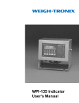
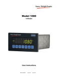
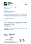
(UK/0126/0008) MI-006 United Kingdom of Great Britain and Northern Ireland Certificate of EC type-examination of a measuring instrument Number: UK/0126/0008 Revision 1 issued by the Secretary of State for Innovation, Universities & Skills Notified Body Number 0126 In accordance with the requirements of the Measuring Instruments (Automatic Catchweighers) Regulations 2006 (SI 2006/1257) and the Measuring Instruments (NonPrescribed Instruments) Regulations 2006 (SI 2006/1270) which implement, in the United Kingdom, Council Directive 2004/22/EC, this certificate of EC type-examination has been issued to: Avery Weigh-Tronix Ltd Foundry Lane Smethwick West Midlands B66 2LP United Kingdom in respect of an automatic catchweighing instrument as described in the descriptive annex and having the following characteristics: Maximum capacity Minimum capacity Accuracy class Max Min Y(a) ≤ ≥ 6000 e 20 e The necessary data (principal characteristics, alterations, securing, functioning etc) for identification purposes and conditions (when applicable) are set out in the descriptive annex to this certificate. This revision replaces previous versions of the certificate. Signatory: for Issue Date: 25 July 2008 Valid Until: 24 June 2017 Reference No: T1110/0010 P R Dixon Chief Executive National Weights & Measures Laboratory Department for Innovation, Universities & Skills Stanton Avenue Teddington Middlesex TW11 0JZ United Kingdom Descriptive Annex 1 INTRODUCTION This pattern of an automatic catchweighing instrument operates as an automatic weight labeller (Category Y). It comprises two weighing devices with associated thermal label printers and mechanical handling facilities and is designed to weigh packs statically. Pack and labelling information is stored in data files, selectable for the commodity and/or labels being processed. Labels are printed with the required transaction data and are applied to packs automatically. 2 FUNCTIONAL DESCRIPTION 2.1 Mechanical 2.1.1 The instrument (Figure 1) is constructed in stainless steel. The supporting framework is a fabricated floor standing stainless steel frame on adjustable feet on which are mounted four modular motorised conveyors (weighing module, scanner module, 2nd weighing module and 2nd scanner module) driven by dc motors. A level indicator is provided on each weighing module. 2.1.2 Each weighing module is connected to an AWTX model 1310 weight indicator (Figure 2) which is mounted below the conveyors with both indicators connected to an AWTX model 1310 controller module which controls the complete system. Label printers/applicators are mounted above each weighing conveyor and fixed barcode scanners are mounted above each scanner conveyor. Four photocells, one per module, are used for pack detection. 2.1.3 The control cabinet is fixed to the front of the stainless steel frame and houses the conveyor based electrical hardware, relay box, operator controls and pneumatics for the label applicators. 2.1.4 Packs are delivered to the first weighing conveyor by the customer supplied infeed conveyor and once detected by the associated photocell the conveyor is stopped by the 1310 controller module for the weighment to take place and the label to be applied. The pack is then transported to the first scanner conveyor where the barcode is read by the scanner. If the data from the scanner is read correctly and agrees with the data stored then the pack continues across the third and fourth conveyor modules without further processing by the system and is transported onto the customer supplied out-feed conveyor. If an error is detected by the scanner the weighing operation is then automatically assigned to the second weighing module and an error signal generated to indicate a fault on the primary weighing module. Once weighed and labelled the pack is then transported to the second scanner module for data integrity checking. 2.2 Electrical 2.2.1 The electrical hardware is located within the 1310 indicator modules, the 1310 control module, thermal label printers and a control panel. The control panel is mounted on the front of the instrument and contains the motor controls with associated power supplies, AWTX SSCU8 relay box and operator controls. 2/9 2.2.2 The control of the instrument is provided by the 1310 controller module which receives product information from the management system and creates the start of shift program and sets the parameters for the weighing modules and label printers/applicators. It includes the same set of electronics as utilised in the weight indicators including the power supplies. 2.2.3 The 1310 weight indicator(s) contain all of the electronics associated with the weighing processes including regulated power supplies, all as described in EC Test certificate GB-1153. 2.3 Load cell Any compatible load cell(s) may be used providing the following conditions are met: − There is a respective OIML Certificate of Conformity (R60) or a Test Certificate (EN45501) issued for the load cell by a Notified Body responsible for type examination under Directive 90/384/EEC. − The certificate contains the load cell types and the necessary load cell data required for the manufacturer's declaration of compatibility of modules (WELMEC 2, Issue 4, 2004, section 11), and any particular installation requirements. A load cell marked NH is allowed only if humidity testing to EN45501 has been conducted on this load cell. − The compatibility of load cells and indicator is established by the manufacturer by means of the compatibility of modules form, contained in the above WELMEC 2 document. − The load transmission conforms to one of the examples detailed in WELMEC 2.4 Guide for Load Cells. 2.4 Devices 2.4.1 The instrument is provided with the following devices: • • • • • • • • • • Semi-automatic zero-setting device (not operable during automatic operation) Automatic zero-setting device (maximum period between zero-setting of 1 hour) Zero-tracking device Zero indicator Tare weighing or balancing device Preset tare device Net indicator Gross (B/G) indicator Real time clock Device to determine when stability criteria are fulfilled 3/9 3 TECHNICAL DATA 3.1 The instrument has the following technical characteristics: Power supply Maximum number of scale intervals Load cell excitation voltage Minimum load cell impedance Maximum load cell impedance Minimum input voltage per verification scale interval Measuring range minimum voltage Measuring range maximum voltage Fraction of maximum permissible error Climatic environment Electromagnetic environment Accuracy class Load cell cable 3.2 220-240 Vac 50/60 Hz 6000 10 Vdc 28 Ω 1100 Ω 2 µV 12 mV 50 mV Pind = 0.5 0 °C to 40 °C Non-condensing (closed) E1 and E2 Y(a) 6 core with braided outer screen. 0.5 mm2 per core, flexible PVC overall jacket Maximum length = 5 m (10 m/mm2). Documentation and drawings Document / Drawing No. EAWI 10001 EAWI 10001 103494_UM V1.1 50692 50693 51571 51572 53021 50799 50800 51631 51632 3.3 Description Functional design specification Software design specification User manual Main PCB assembly Main PCB circuit diagram Multi-channel analogue output PCB assembly Multi-channel analogue output board circuit diagram Network interface PCB assembly Serial I/O and PSU PCB assembly Serial I/O and PSU circuit diagram Display and keyboard interface PCB assembly Display and keyboard interface PCB circuit diagram Software 3.3.1 The weighing software is contained within the 1310 indicator modules and the version number is 52957-0137. The software version number is accessed by: − − Hold in the escape key until the indicator beeps. For the User Menu, enter the password: 111 and press the enter key. 4/9 − − From the User menu, press the soft-key marked “VIEW”. From the View menu, press the soft-key marked “VERS”. 3.3.2 The main process control software is contained within the 1310 controller module and its version number is V1.2.x.x, where .x.x denotes a sequential number (starting with .0.1) detailing the exact release level. Any changes denoted by the release level .x.x will be nonmetrologically significant. The indicator modules also include a limited version of the controller module software and the version number is V1.3. The version numbers for both units are displayed at power up and the checksum value is accessed by: − − − − − − − Hold in the escape key until the indicator beeps. For the User Menu, enter the password: 111 and press the enter key. From the User menu, press the soft-key marked “VIEW”. From the View menu, press the soft-key marked “VERS”. Sequence through the screens to view the details of the software embedded in the 1310 indicator. The identity and checksum of the Weighing Application are given on the fifth screen, titled “SIMPOSER CONFIGURATION FILE”. On this screen, five comma separated fields are given. The fields in order are : Indicator Model The tool version used to download the file. The file name, used as the checksum, of the programmed software. The time the software was downloaded. The date the software was downloaded. 3.3.3 The 1310 controller module transmits the tare weight to each 1310 weighing module. The tare value is stored in the PLU selected on the 1310 controller module. 3.3.4 Each label printed and applied to the packs is provided with a sequential number. The sequential number is unique to each 1310 weighing module and identifies the stored data string for each pack. 4 PERIPHERAL DEVICES AND INTERFACES 4.1 Interfaces • • • 4.2 Load cell connection (hardwired). 3 x RS232/RS422 1 x powered RS422 (20 mA) Peripheral devices The instrument may be connected to any peripheral device that has been issued with a test certificate by a Notified Body responsible for Annex B (MI-006) under Directive 2004/22/EC in any Member State and bears the CE marking of conformity to the relevant directives; or 5/9 A peripheral device without a test certificate may be connected under the following conditions: 5 − it bears the CE marking for conformity to the EMC Directive 89/336/EEC; − it is not capable of transmitting any data or instruction into the weighing instrument, other than to release a printout, checking for correct data transmission or validation; − it prints weighing results and other data as received from the weighing instrument without any modification or further processing; and − it complies with the applicable requirements of Directive 2004/22/EC Paragraph 8.1 of Annex I. APPROVAL CONDITIONS The certificate is issued subject to the following conditions: 5.1 Legends and inscriptions 5.1.1 The following legends are durably and legibly marked on the instrument: ‘CE’ marking Supplementary metrology marking Notified body identification number Accuracy class Serial number Manufacturers mark or name Certificate number Operating temperature range 5.2 indicator. If the instrument is not permanently installed it shall be provided with a level 6 LOCATION OF SEALS AND VERIFICATION MARKS 6.1 The “CE” marking, supplementary metrology marking and certificate number are located on the mounting plate bracket which is fixed to the main structure of the conveyor stand. The CE mark shall be impossible to remove without damaging it. The data plate (Figure 3) shall be impossible to remove without it being destroyed. The markings and inscriptions shall fulfil the requirements of Paragraph 9 of Annex I of the Directive 2004/22/EC. 6.2 Access to the configuration and calibration facility for the 1310 weighing module(s) is via a push button located on the power supply PCB and is accessed through a hole in the rear of the indicators enclosure. The plastic screw, which prevents access to the push button, can be secured to the back of the enclosure by a wire and seal. Components that may not be dismantled or adjusted by the user (including the load cell junction box if applicable) must be secured by either a wire and seal or a tamper evident label and securing mark. 6/9 The securing mark may be either: − − 7 a mark of the manufacturer and/or manufacturer’s representative, or an official mark of a verification officer. ALTERNATIVES There are no alternatives. 8 ILLUSTRATIONS Figure 1 Figure 2 Figure 3 Photograph of the instrument 1310 indicator Data plate 9 CERTIFICATE HISTORY ISSUE NO. DATE DESCRIPTION UK/0126/0008 25 June 2007 Type examination certificate first issued. UK/0126/0008 Revision 1 25 July 2008 Modification to section 3.3.2. 7/9 Figure 1 Photograph of the instrument Figure 2 1310 indicator 8/9 Figure 3 Data plate Crown Copyright 2008 NATIONAL WEIGHTS AND MEASURES LABORATORY Department for Innovation, Universities & Skills 9/9