1
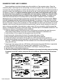
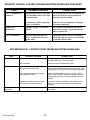
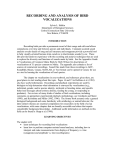
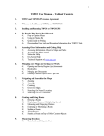
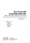
Operation, Installation & Maintenance
7/02
L-2168
PREFACE
Congratulations on the purchase of your Marine Air Systems’ VECTOR COMPACT® air conditioner.
No matter which of the following features was the reason for your purchase of this air conditioner, we
are sure it will meet your needs and will give you many years of efficient and trouble free use. The
Vector Compact self-contained direct expansion air conditioners are designed for marine applications
incorporating the following features:
•
•
•
•
•
•
•
•
•
Patented compact design with the condenser coil in the evaporator shroud
High efficiency rotary compressor (7-16K) or scroll (24K) compressors
Cupronickel condenser coil
Raised lance fin designed evaporator coil
Polyurethane coated 2” deep drain pan with multiple condensate drain locations
Anti-vibration base pan
Pre-charged and pre-wired systems for easy connections
Rotatable blower assembly
Charge Guard® ensures environmental protection and system integrity
The PASSPORT® II micropressor based digital controller, optional with this unit, offers the most
technologically advanced design specifically made for the unique requirements of marine air conditioning. The controller has been designed with flexibilty and the following “user friendly” features
customers require for their applications:
• Non-volatime memory
• Program lock prevents accidental program tampering
• Low voltage display panel
• Face plate air sensor for accurate temperature control, or optional remote sensor
• LED cabin temperature displayed in Fahrenheit or Celsius
• Multiple fan speed selections with high and low limits
• User selected programs for optimum control
• Optional outside air temperature sensor
• Compressor pressure failsafe protection and run time hour meter
• Compressor start staging delay for multiple a/c systems
• Moisture mode cycle for humidity control
• De-icing feature to prevent evaporator icing
• Blank display for nighttime operation
This manual is intended to provide the information necessary to ensure proper installation, operation,
and maintenance of the unit. Improper installation or misunderstood operating procedures can result
in unsatisfactory performance and/or premature failure of these units, so before proceeding please
read this manual completely.
The Vector Compact® units are covered under the existing Taylor Made Environmental, Inc. warranty
policy contained in this manual. In the interest of product improvement, Taylor Made Enviornmental’s
specifications and design are subject to change without prior notice.
REVISION HISTORY
Document Name: vectorcompact
Original Print: March 1998
Revised: 5/98, 7/98, 11/98, 11/01, & 7/02
®Taylor★Made is a registered trademark of Nelson A. Taylor Co., Inc; The Marine Air Systems logo, Vector Compact, Charge Guard, and Passport are registered trademarks and
the Taylor Made Environmental logo is a trademark of Taylor Made Environmental, Inc.
CLEAN AIR ACT AMENDMENTS OF 1990 [TITLE VI - SECTION 608(C-1)]
“Effective July 1, 1992, it shall be unlawful for any person, in the course of maintaining, servicing, repairing, or
disposing of an appliance or industrial process refrigeration, to knowingly vent or otherwise knowingly release or
dispose of any Class I* or Class II** substance used as a refrigerant in such appliance (or industrial process
refrigeration) in a manner which permits such substance to enter the environment. De minimis releases associated
with good faith attempts to recapture and recycle or safely dispose of any such substances shall not be subject to
the prohibition set forth in the proceeding sentence.”
*Class I substances include CFC-12
**Class II substances include HCFC-22
MARINE AIR SYSTEMS
Marine Air Systems (MAS) is a product of Taylor Made Environmental, Inc (TME). TME is a recognized leader
in the design and manufacture of high-performance comfort control systems, refrigeration products and battery
charging products for demanding environments, including commercial and recreational marine craft, vehicles and
other applications. We offer an unparalleled scope of products, dealer networks, applications support, engineering
resources and production capabilities throughout the world. Our team has many years of experience in the design,
manufacture, application and support of our products. Our practical experience and design capability allows our
application engineers and sales representatives to offer optimum solutions for your environmental control requirements. Product lines also include well known Cruisair, Grunert, and Sentry. TME is a Member of the Taylor Made
Group.
OVERVIEW
HOW IT WORKS:
Your self-contained air conditioner consists of four main components and a refrigerant gas circulating
through the system. The BLOWER draws warm cabin air across the fins on the EVAPORATOR where
the heat from the air is transferred to the refrigerant in the evaporator coil. As the refrigerant
evaporates from a liquid into a gas it absorbs the heat from the cabin air. The COMPRESSOR then
compresses the refrigerant gas and pumps it through the outer tube in the CONDENSER COIL. The
seawater pump circulates cool seawater through the inner tube in the condenser coil, this cools the
refrigerant and condenses it into a liquid. The heat from the refrigerant is exchanged to the seawater
and discharged overboard. The liquid refrigerant is then passed through the EVAPORATOR COIL and
the cycle repeats. Removing heat from the cabin air lowers its temperature. The cooled air is blown
through the ducting and out the supply air grille(s). For reverse cycle heating, the refrigerant flows in the opposite
direction through the reversing valve. Heat is transferred from the seawater in the condenser coil to the refrigerant
and then to the air blowing through the evaporator into the cabin. Seawater temperature will directly affect the a/c
unit’s efficiency. This a/c unit can effectively cool your boat in water temperatures up to 90oF and heat in water
temperatures as low as 40oF.
Vector Compact®
4
TABLE OF CONTENTS
INSTALLATION
Unpacking and Inspection
Safety Considerations
Placement of System (Tools Required)
Spacing Allowances & Unit Dimensions
Condensate Drains
Blower Assembly
Mounting Brackets
Supply & Return Air Grilles and Transition Boxes
Ducting
Seawater Pump and Plumbing
Electrical Connections, Grounding, Bonding & ABYC standards
3 Phase Notice
Manual Control Panel (MCP) Installation
Passport II Display Panel Installation
Installation Checklist (review prior to and after installation)
Vector Compact Mechanical Control (VCM) Wiring Diagrams
Vector Compact Passport II Digital Control (VCP) Wiring Diagrams
6
6
7
8
9
9
9
10
10
11
12
12
13
14
15
16
17
OPERATION
Manual Control Panel (MCP) Operation
Quick Start Operations Checklist
Passport®II Control
Modes of Operation
Programming the Passport®II
Programming Notes
General Troubleshooting Guidelines
Passport®II Digital Control Troubleshooting Guidelines
MCP Mechanical Control Panel Troubleshooting Guidelines
13
15
18
18,19
19-22
22
23, 24
25, 26
26
MAINTENANCE
Reversing Valve, Seawater System, Blowers, Condensing Coil Cleaning,
Return Air Filters, Winterization
Manufacturers Limited Warranty Agreement
Distributor Listing
27
29
31
Vector Compact®
5
INSTALLATION
UNPACKING AND INSPECTION
When the equipment is received, all items should be carefully checked against the packing list to ensure
all cartons have been received. Move units in the normal “up” orientation as indicated by the arrows on
each carton. Examine cartons for shipping damage, removing the units from the cartons if necessary. If
the unit is damaged, the carrier should make the proper notation on the delivery receipt acknowledging
the damage.
CAUTION: When unpacking and installing the 2 knob control (if mechanical option is used), care must be
taken not to kink or break the copper cap tube when uncoiling the sensing bulb. The cap tube is hollow
and kinking or sharp bends will inhibit system operation.
SAFETY CONSIDERATIONS
VERY IMPORTANT: Never install your air conditioner in the bilge or engine room areas. Insure that
the selected location is sealed from direct access to bilge and/or engine room vapors. Do not
terminate condensate drain line within three (3) feet of any outlet of engine or generator exhaust
systems, nor in a compartment housing an engine or generator, nor in a bilge, unless the drain is
connected properly to a sealed condensate or shower sump pump.
Installation and servicing of this system can be hazardous due to system pressure and electrical components. When working on this equipment, always observe precautions described in the literature, tags and
labels attached to the unit. Follow all safety codes. Wear safety glasses and work gloves and place a fire
extinguisher close to the work area. The following is a summary of the labels on the unit:
! DANGER ELECTRICAL SHOCK HAZARD. DISCONNECT VOLTAGE AT MAIN PANEL OR POWER
SOURCE BEFORE OPENING ANY COVER. FAILURE TO COMPLY MAY RESULT IN INJURY OR
DEATH.
! WARNING THIS COMPONENT DOES NOT MEET FEDERAL REQUIREMENTS FOR IGNITION
PROTECTION. DO NOT INSTALL IN SPACES CONTAINING GASOLINE ENGINES, TANKS, LPG/CPG
CYLINDERS, REGULATORS, VALVES OR FUEL LINE FITTINGS. FAILURE TO COMPLY MAY RESULT
IN INJURY OR DEATH
NOTICE THIS COMPONENT IS CHARGED WITH HYDROCHLOROFLUOROCARBON (HCFC) REFRIGERANT R22. EFFECTIVE JULY 1, 1992 IT SHALL BE UNLAWFUL FOR ANY PERSON TO
KNOWINGLY VENT OR OTHERWISE KNOWINGLY RELEASE ANY CLASS 1 (CFC) OR CLASS 2
(HCFC) SUBSTANCE AS A REFRIGERANT IN A MANNER WHICH PERMITS SUCH SUBSTANCE TO
ENTER THE ATMOSPHERE PER THE CLEAN AIR ACT OF 1990. PUBLIC LAW 101-549 TITLE IV
SECTION 608-C. FAILURE TO COMPLY MAY RESULT IN SEVERE PENALTIES, INCLUDING FINES
AND IMPRISONMENT.
! WARNING TO MINIMIZE THE HAZARD OF ELECTRICAL SHOCK AND PERSONAL INJURY, THIS
COMPONENT MUST BE EFFECTIVELY GROUNDED. REFER TO THE INSTALLATION GUIDELINES
FOR FURTHER INFORMATION.
CAUTION! HIGH COMPRESSOR TEMPERATURE IS NORMAL DO NOT TOUCH
Vector Compact®
6
PLACEMENT OF SYSTEM
Selecting a good location for your air conditioner is the most important part of your preparations. Be sure to
consider the size of the area you are cooling, the air distribution needs, and the size of the unit you have
chosen. Keeping in mind that cool air has a tendency to fall, it is highly recommended that you locate the
supply air grille as high as possible in the cabin. See diagram below.
The VECTOR COMPACT unit should be installed as low as
possible, BUT NEVER IN THE BILGE OR ENGINE ROOM
AREAS. INSURE THAT THE SELECTED LOCATION IS
SEALED FROM DIRECT ACCESS TO BILGE AND/OR ENGINE ROOM VAPORS. Installing the unit as low as possible
(such as under a V-berth, dinette seat or bottom of a locker)
and ducting the supply air as high as possible, creates an
ideal air flow condition. This type of installation will prevent
short or premature cycling.
The unit should be positioned on a firm, level, horizontal
surface and the condensate drain line should run downward from the unit to a suitable drain location. Plan all
connections which must be made including ducting, condensate drain, seawater in and out, electrical power connections, location of control, and seawater pump placement, to
assure easy access for routing and servicing.
Vector Compact®
7
Tools required
•
•
•
•
•
•
•
•
•
•
•
Screws drivers
Pliers
Pipe wrench
Wire cutters/crimpers
Drill & 7/8” bit
Jig saw
Duct tape
Electrical tape
Teflon tape
Beding compound to seal thru hull fittings
Hardware to secure unit, pump, strainer,
grilles & control panel
Vector Compact®
8
CONDENSATE DRAINS
The condensate drain pan is 1¾” high with four drain
locations. During conditions of high humidity, condensate may
be produced at a rate of approximately ½ gallon per hour. With
this in mind, it is important to route condensate drains downward
to a sump pump. It is not recommended to route condensate
drains to the bilge. After the condensate drain installation is
complete, test the installation by pouring a quart of water into the
pan and checking for good flow.
For installation of the condensate drain:
1. Remove the aft facing watertight plug from the base pan of the a/c unit.
2. Slip the solid washer and the liquid-seal washer onto the PVC fitting in that order.
3. Connect the fitting through the exposed hole in the base pan with the locking nut.
4. Securely tighten with two (2) wrenches to provide a proper seal.
5. Attach a 5/8” I.D. reinforced hose to the hose barb and secure with stainless steel hose clamps.
6. Install the condensate drain hose downhill from the unit and aft to a sump.
7. Two drain fittings may be used and the hoses teed together provided there is a minimum 2" drop
form the bottom of the base pan to the tee connection.
NOTE: DO NOT TERMINATE CONDENSATE DRAIN LINE WITHIN THREE (3) FEET OF
ANY OUTLET OF ENGINE OR GENERATOR EXHAUST SYSTEMS, NOR IN A
COMPARTMENT HOUSING AN ENGINE OR GENERATOR, NOR IN A BILGE, UNLESS THE
DRAIN IS CONNECTED PROPERLY TO A SEALED CONDENSATE OR SHOWER SUMP
PUMP.
BLOWER ASSEMBLY
With the VECTOR COMPACT® you can achieve multi-directional supply air discharge from a single
unit by rotating the blower to the desired location. It is ideal for tight installations as 130o of rotation are
available with which to position the blower. Its advanced design allows the blower to be easily removed
for rotating or servicing by releasing a single stainless steel clamp and two (2) mounting ring screws.
Rotate the blower to allow the most direct flow of air to the supply air grille.
MOUNTING BRACKETS
The a/c unit is supplied with a base pan that also serves as
a condensate pan. Mounting clip brackets and screws (4) are
provided to secure the base pan onto a flat, horizontal surface.
Vector Compact®
9
SUPPLY & RETURN AIR GRILLES AND TRANSITION BOXES
Install the supply air grille as high as possible in a location that will provide uniform air distribution
throughout the cabin, grille louvers should be directed upward. The return air grille should be installed as
low and close to the a/c unit as possible to insure direct uninteruppted airflow to the evaporator. The
return air grille should have a minimum four inches (4”) of clearance in front of it, free from any furniture or
other obstructions. In no instance should a supply air discharge be directed towards a return air grille, as
this will cause the system to short cycle. Allow for adequate clearance behind the supply air grille(s) for
the transition box and ducting connection. The following table shows minimum grille sizes. See the
MAINTENANCE section of this manual for return air filter cleaning instructions.
DUCTING
Good airflow is critical for the performance of the entire system. It is highly dependent on the
quality of the ducting installation. The ducting should be run as straight, smooth and taut as possible
minimizing the number of 90 degree bends (two tight 90 degree bends can reduce airflow by 25%). The
following table shows minimum duct diameters and their corresponding supply and return air grille minimum area in square inches. If a transition box is used, the total area of supply air ducts going out of the
box should at least equal the area of the supply duct feeding the box. To calculate the square inch area of
a round duct, multiply the radius by itself (r2) and multiply that number by 3.1416(π).
MODEL
5K
7K
10K
12K
16K
24K
4" dia.
5" dia.
6" dia
6" dia
7" dia
8" dia
DUCT AREA
12.6 sq in
19.6 sq in
28.3 sq in
28.3 sq in
38.5 sq in
50.3 sq in
R/A GRILLE
64 sq in
88 sq in
120 sq in
140 sq in
168 sq in
280 sq in
S/A GRILLE
30 sq in
40 sq in
60 sq in
70 sq in
84 sq in
140 sq in
DUCT DIA
The following is a summary of proper ducting connections:
1. Pull back the fiberglass insulation exposing the inner mylar duct hose.
2. Slide the mylar duct hose around the mount ring until it bottoms out.
3. Screw 3 or 4 stainless steel sheet metal screws through the duct hose into the transition ring.
Make sure to catch the wire in the duct hose with the heads of the screws. Do not use band
clamps, as the hose will slide off.
4. Wrap duct tape around the ducting and ring joint to prevent any air leaks.
5. Pull the insulation back up over the mylar to the ring and tape this joint.
6. Remove excess ducting and use the same connection method at the supply air grille.
All ducting should:
• Be appropriately sized for each application.
• Run as smoothly and taut as possible.
• Have as few bends or loops as possible.
• Be securely fastened to prevent sagging during boat operation.
• Have all excess ducting lengths trimmed off.
• Not be flattened or kinked.
• Insulated when located in high heat load areas (hull side, mechanical compartments, etc.).
• Be properly protected against potential damage when routed through open areas.
Vector Compact®
10
SEAWATER PUMP AND PLUMBING
Several guidelines should be followed during the installation of the seawater system. Since the
circulation pump is centrifugal and not self-priming, it must be mounted so that it is always at least one
foot below the water line regardless of which tack the vessel is on. Pump may be mounted horizontally or
vertically, however the discharge must always be above the inlet. Pump head should be rotated toward
the direction of water flow. Install the seawater speed scoop intake as far below the water line and
as close to the keel as possible in any application, but especially on a sailboat, to keep the intake
in the water when the boat heels over so that air does not get into the system. The speed scoop
intake must face forward and not be shared with any other pump. A seawater strainer is mandatory
between the shut off valve (seacock) and the pump to protect the pump from any foreign matter. Failure
to install a seawater strainer will void the pump warranty. The seawater system should be installed
with an upward incline from the speed scoop & seacock, through the strainer, to the inlet of the pump and
then up to the inlet of the a/c unit’s condenser coil. The discharge from the a/c unit should then run to the
seawater outlet thru-hull fitting which should be located where it can be visually checked for water flow
and as close as practicable to the waterline to reduce noise. All hose connections shall be secured by
means of double/reversed stainless steel hose clamps. Use teflon tape on all threaded connections. The
following is a summary of the seawater system installation:
1. Install the speed scoop thru-hull inlet as close to the keel and as far below the water line as possible, facing forward. Bed the scoop with a marine sealant designed for underwater use.
2. Install a bronze, full flow seacock on the speed scoop thru-hull inlet.
3. Install a seawater strainer below the level of the pump with access to filter.
4. Mount the pump above the strainer and at least one foot below the waterline.
5. Connect the seacock and strainer with an uphill run of 5/8" reinforced marine grade hose.
6. Connect the discharge from the pump uphill to the bottom inlet of the a/c unit’s condenser coil with
5/8" hose. Connect the discharge from the condenser coil to the overboard discharge thru-hull
fitting with 5/8" hose.
7. Avoid loops, high spots or the use of 90º elbows with seawater hose (each 90º elbow is equivalent
to 2.5' of hose and a 90º elbow on the pump outlet is equivalent to 20' of hose).
8. Double clamp all hose connections with stainless steel clamps, reversing the clamps.
9. Use teflon tape on all threaded connections.
10. Connect all metallic parts in contact with seawater to the vessel’s bonding system including
the speed scoop inlet, strainer, pump and the air conditioner. Failure to do so will void warranty.
Vector Compact®
11
ELECTRICAL CONNECTIONS, GROUNDING AND BONDING
All a/c units have a terminal strip mounted inside the electric box. The terminal strip is labeled for proper
connections of the electrical supply, ground wires and pump circuits. A wiring diagram is provided in the
electrical box and in this manual. The wiring diagram in the elcetrical box supersedes the one in this
manual and ABYC standards. The correct size circuit breaker should be used to protect the system as
specified on the a/c unit’s data plate label. A minimum of 12 AWG boat cable should be used to supply
power to the a/c unit and the seawater pump. All connections shall be made with ring or fork terminals.
Turn off a/c power supply circuit breaker before opening electric box.
Each a/c unit installed requires its own dedicated circuit breaker. If there is only one a/c unit installed, the
seawater pump does not require a circuit breaker; the wiring from the seawater pump is connected to the
terminal strip in the electric box. If two or more a/c units use the same seawater pump, the pump wires will
be connected to a pump relay panel (PRP) which in turn has its own dedicated circuit breaker sized for
the pump (20 amp max). Please see the wiring diagram furnished with the PRP (NOTE: PRP triac must
have its mounting screw installed in order to dissipate heat). Electrical connections in the bilge and/or
below the waterline should use heat shrink type butt splices.
Field wiring must comply with ABYC electrical codes. Power to the unit must be within the operating
voltage range indicated on the data plate. Properly sized fuses or HACR circuit breakers must be installed for branch circuit protection. See data plate for maximum fuse/circuit breaker size (mfs) and minimum circuit ampacity (mca). All units must be effectively grounded to minimize the hazard of electrical
shock and personal injury.
The following are to be observed:
1. AC (alternating current) grounding (green wire) must be provided with the AC power conductors
and connected to the ground terminal (marked “GRND”) at the AC power input terminal block of
the unit(s), per ABYC standard E-8, or equivalent.
2. Connections between the vessel’s AC system grounding conductor (green wire) and the vessel’s
DC (Direct Current) negative or bonding system should be made as part of the vessel’s wiring,
per ABYC standard E-9, or equivalent.
3. When servicing or replacing existing equipment that contains a chassis-mounted ground stud,
the service person or installer must check the vessel’s wiring for the existence of the connection
required in item 2 above.
ABYC standards are available from: American Boat and Yacht Council, 3069 Solomons Island Rd.
Edgewater, MD 21036 Telephone: (410) 956-1050
The a/c unit must be connected to the ship’s bonding system to prevent corrosion due to stray
electrical current or voltage. All pumps, metallic valves and fittings in the seawater circuit that are
isolated from the a/c unit by PVC or rubber hoses must be individually bonded to the vessels bonding
system also. This will help eliminate any possibility of corrosion due to stray current or voltage.
FAILURE TO PROPERLY GROUND AND BOND THE SYSTEM WILL VOID WARRANTY!
3 PHASE NOTICE
It is extremely important to insure that wiring and phase sequencing of a three phase power source is
correct. Marine wiring standards call for power source phases L1, L2, and L3 to be color-coded BLACK,
WHITE, and RED, respectively. These must be connected to the unit with the proper sequence, otherwise, it will not operate properly. If the wiring sequence is incorrect, the unit’s compressor (Scroll type
only) and pump (if applicable) will run in the reverse direction at a significantly increased noise level.
Vector Compact®
12
MANUAL CONTROL PANEL (MCP) INSTALLATION
The MCP should be located within cap tube length of the a/c unit. The 3 knob MCP is configured either
vertically (shown) or horizontally. The cut out size is 2.5” by 7.0”, see MCP for orientation. Once the cut out
is made, carefully uncoil the copper cap tube with return air sensor (copper bulb) and route the control
wires and cap tube through the hole and back to the a/c unit using caution not to kink the cap tube.
Mount the return air sensor into the clips provided on the evaporator coil. If the return air sensor cannot be
mounted on the evaporator coil, mount it behind the return air grille. The sensor must be mounted in the
return air stream. Make electrical connections according to the wiring diagram found in the electric box
and/or in the operations manual.
MCP OPERATION
1) Ensure seawater intake ball valve (sea cock) is open.
2) Turn SYSTEM SWITCH control knob to OFF.
3) Turn on AC circuit breaker. If the seawater pump has its own
circuit breaker, turn that on too.
4) Turn the SYSTEM SWITCH control knob to START; this
energizes the fan and seawater pump. Turn THERMOSTAT
control knob to the coolest position by rotating fully clockwise.
If system has reverse cycle, turn knob counter-clockwise for
heat.
5) Check for a steady solid stream of seawater from the overboard discharge.
6) Turn FAN SPEED control knob clockwise to highest setting.
7) Verify that the fan is running and that there is steady airflow
out of the supply air grille.
8) Turn the SYSTEM SWITCH to RUN; this will start the compressor. The indicator light on the control will illuminate.
9) To set the thermostat, allow sufficient time for the unit to cool/
heat the area to the desired temperature. When the area is
sufficiently cooled/heated, turn the thermostat knob slowly
toward the center position until it clicks once (the indicator
light will turn off). The thermostat is now set to maintain a
constant temperature. While heating, if the ambient temperature is less than 500F, set the FAN SPEED control knob to
low for five to ten minutes until the unit begins to heat well,
then increase the fan speed for more heat output.
The thermostat on the MCP control panel serves to cycle the
compressor on and off and provide an automatic changeover
from cooling to heating (reverse cycle only) with a 3.5( differential. Rotating the thermostat to the left after it
has been set for cooling will cause the unit to heat. If you rotate the thermostat to the right, the unit will
cool. If the thermostat is left stationary after being set, the unit will cycle from cooling to neutral, or heating
to neutral depending on the requirement.
Reverse cycle units have a reversing valve that must be energized periodically to keep the internal parts
moving freely. To accomplish this, switch the A/C into HEAT for a few seconds once a month.
Note: Do not turn the unit off and immediately turn it back on. Wait at least 30 seconds.
Vector Compact®
13
PASSPORT II DISPLAY PANEL INSTALLATION
Before mounting the Passport II digital display panel touch pad, consider the location. The air sensor built
into the display panel will provide excellent room air temperature sensing given a proper installation. The
display panel should be mounted on an inside wall, slightly higher than mid-height of the cabin, in a location with freely circulating air where it can best sense average temperature. The cut out size for the display
panel is 3” wide by 2”( high. Do not mount the display in direct sunlight, near any heat producing appliances or in a bulkhead where temperatures radiating from behind the panel may effect performance. Do
not mount the display in the supply air stream. Do not mount the display above or below a supply or
return air grille. Do not mount the display behind a door, in a corner, under a stairwell or any place where
there is no freely circulating air. Mount the display within display cable length (custom lengths available)
of the air conditioner. Plug the display cable (15”/4.6m standard length with 8-pin connector) into the
circuit board in the electric box and into the back of the display panel. Secure the display panel to a bulkhead with the adhesive strips provided. Clean the mounting surface with isopropyl alcohol only prior to
placement (test alcohol on hidden portion of surface first). If the adhesive strips cannot be used directly on
the bulkhead then use the plastic bulkhead adapter. The bulkhead adapter (sold separately) is mounted to
the bulkhead with screws and the display panel is secured to the adapter with adhesive strips. Do not
use a screw gun and do not over-tighten screws when mounting adapter.
If a proper location for room temperature sensing cannot be found for the display, an optional remote air
sensor may be used. Mount the remote air sensor in the return air stream behind the return air grille opening and plug its cable (7’/2.1m standard length with 6-pin connector) into socket #J2 on the circuit board
(socket nearest the corner of the board). Installing the remote air sensor will override the face plate sensor.
An optional outside air temperature (O.A.T.) sensor and cable may also be used. Plug the O.A.T. cable into
the 6-pin socket #J3. Mount the sensor outside in a protected location and not in direct sunlight. Air sensor cables are available in various lengths. Secure all cables but do not staple when mounting.
Vector Compact®
14
INSTALLATION CHECKLIST (review prior to installation)
Seawater cooling system:
❍
Speed scoop located as far below the water line and as close to the keel as possible
❍
Shut off valve (sea cock) and speed scoop properly sealed and tight
❍
Seawater pump is at least one foot below water line and securely mounted
❍
Strainer mounted below pump with access to filter
❍
Double/reversed stainless steel hose clamps on all hose connections
❍
Teflon tape on all threaded connections
❍
Hose runs uphill from speed scoop and sea cock to strainer, pump and a/c unit, then downhill
(if possible) from a/c unit to overboard discharge
❍
Water flowing freely from overboard discharge while pump is running
❍
Pump relay panel, if used, must have its own circuit breaker sized for the pump (20 amp max)
❍
All metal fittings should be bonded
Mounting
❍
Not in engine room or bilge areas, must be sealed away from exhaust or fumes
❍
Proper spacing allowed around unit
❍
Attached to solid level platform with hold down clips provided
❍
Condensate drain routed aft and down hill to a sealed sump (not bilge)
❍
Blower rotated toward supply air grille
Electrical
❍
All butt connections on pumps wire tightly crimped and heat shrunk
❍
AC power source installed and grounded/bonded in accordance with ABYC standards
❍
Control wires connected to terminal strip with fork or ring terminals
❍
Circuit breakers sized according to specifications on the data plate label
❍
Passport II display cable is connected at both ends
❍
Pump Relay Panel (if used) has a dedicated circuit breaker sized for the pump but not to exceed 20
amps maximum.
Grilles and Ducting
❍
Supply air grille mounted as high as possible
❍
Return air grille mounted as low and as close to the a/c unit as possible
❍
Return air grille mounted away from bilge vapors or exhaust fumes
❍
Ducting is pulled taut, straight, smooth and properly connected with no excess
QUICK START OPERATIONS CHECKLIST
❍
❍
❍
❍
❍
❍
❍
Ensure seawater intake ball valve (sea cock) is open.
Turn on the a/c circuit breaker. If the seawater pump has its own circuit breaker, turn that on.
Turn the system on.
Set the desired cabin temperature (set point).
Check for a steady solid stream of water from the overboard discharge.
Verify that there is steady airflow out of the supply air grille.
If the unit does not appear to be operating properly, refer to troubleshooting guide lines.
Note: Do not turn the unit off and immediately turn it back on. Allow at least 30 seconds for
refrigerant pressure equalization.
Vector Compact®
15
Vector Compact®
16
Vector Compact®
17
PASSPORT II CONTROL
POWER BUTTON: Press and release to turn unit on and off.
NOTE: To “press and release” a button, press and hold for one second and then release.
FAN BUTTON: Press and hold until the letter “A” appears for automatic fan speed or the numbers “1” (slow)
through “6” (fast) appear for manual fan speed. Fan may be used while a/c is off.
UP & DOWN BUTTONS: Press and hold either button until desired temperature (set point) is
displayed. Press either button momentarily to show current set point. Range = 600-850F.
COOL LED: Lights when the compressor is running in cool mode or in automatic mode while cooling.
FAN LED: Lights when fan is on in manual mode.
HEAT LED: Lights when the compressor is running in heat mode, or automatic mode while heating.
DISPLAY WINDOW: Shows current cabin temperature. It can also show outside air temperature if the optional
O.A.T. sensor is installed. Also used in viewing and setting program parameters.
AIR SENSOR: Cabin temperature is detected by the face plate air sensor, located in the bottom edge of the display. A remote air sensor can be installed if needed. Installing the remote air sensor will override the face plate
sensor.
BLANK DISPLAY FOR NIGHTTIME OPERATION: Press the FAN and DOWN buttons simultaneously to blank
the display for nighttime operation. The appropriate LEDs will remain lit during cooling and heating. When the
desired temperature has been achieved, the middle segment of the display window will remain lit to indicate that the
system is on. Press any button to return to normal display mode.
OUTSIDE AIR TEMPERATURE: When the optional outside air sensor is installed, press the UP and DOWN
buttons simultaneously to display the outside air temperature. The outside air sensor should not be mounted in
direct sunlight.
MODES OF OPERATION
COOL ONLY MODE: When the Passport II is configured for cool only mode, only cooling systems will be operated
as required. When the temperature drops below the set point the system will not automatically switch into the
heating mode.
HEAT ONLY MODE: When the controller is programmed for heating mode, only the heating system will be selected
for operation as required. Should the temperature rise above the set point the system will not switch to the cooling
mode automatically.
AUTOMATIC MODE: When the controller is configured for the automatic mode, both heating and cooling will be
supplied as required. The heat and cool LED indicators will light according to which mode is operating. Temperature differential in a given mode will be maintained at 20F, however, a 40F difference is required to allow the control
to change modes.
HUMIDITY MODE: While the system is on, press the POWER and the DOWN buttons simultaneously to enter the
Vector Compact®
18
humidity or moisture control mode. The characters “HU-1” will appear in the temperature display. Every four
hours, the fan is started and air is circulated for thirty minutes. During this time the air temperature is sampled and
entered into memory. The cooling cycle is then started and continues until the temperature is lowered 20F. The
compressor is allowed a maximum of one hour running time to reach the desired temperature. Four hours after the
temperature is satisfied or the compressor times out, the cycle is repeated. During the cycle, the cool LED will be
lit when the compressor is running. Humidity mode is provided to maintain a specific temperature and humidity
range when the vessel is unoccupied for extended periods of time.
AUTOMATIC FAN MODE: Press and hold the FAN button until the letter “A” appears in the display window. Automatic fan mode allows the control to determine fan speeds based on the room temperature. The closer the room
temperature gets to the set point, the slower the fan will run while in cool mode. This permits a balance between
the most efficient temperature control and the slowest fan speed. See programmable parameter “U 9” to reverse
the fan speeds while in heat mode. The fan LED will not be lit during automatic fan mode.
MANUAL FAN MODE: Press and hold the FAN button during normal operation to select one of the six manual fan
speeds available. Six (6) is the highest and one (1) represents the lowest speed available. When a manual fan
speed has been selected the fan LED will be lit.
NOTE: High and low fan speeds can be further tailored to suit the user by adjusting the fan limits. See programming modes “U 2” and “U 3”.
CIRCULATION MODE (FAN ONLY): With the system off, press and hold the FAN button until the desired fan
speed is indicated by the numbers “1” (slow) through “6” (fast). To turn the fan off press and hold the FAN button
until the number “0” appears in the display window.
PROGRAMMING THE PASSPORT II
The program mode is used to adjust operating parameters to tailor the system for efficient operation and to allow
for user flexibility. Installation variables such as ducting, sensor location and system layout effect the operation of
the overall system. Custom programming allows the system to operate as efficiently as possible in any given
installation.
TO ENTER PROGRAM MODE: With the system off, press and hold the POWER button for five seconds until the
letter “U” appears in the display window. Release the button and the first parameter setting appears followed by
“U 1”.
TO UNLOCK PROGRAM MODE: After entering the program mode, simultaneously press and release the
POWER and DOWN buttons.
TO SELECT PROGRAM PARAMETER: Press and hold the FAN button to scroll through the parameters indicated by the program number. Programs are described in the following table.
TO CHANGE THE PROGRAM PARAMETER: Use the UP and DOWN buttons to select data or set the desired
limits. The range of parameter settings is listed in the following table.
TO RESET DEFAULT SETTINGS: With the system off, press and hold the POWER button for ten seconds until
the software version number (A##) appears in the display window.
TO LOCK NEW DEFAULT SETTINGS: Once the desired program changes have been made and before exiting
the program mode, simultaneously press and release the UP and DOWN buttons. Locking new defaults will
render the factory defaults obsolete. Make note of the new defaults in the following chart for future reference.
TO EXIT PROGRAM MODE: Press the POWER button or press no button for sixty seconds. The software
version number is displayed for one second prior to exiting the program mode.
Vector Compact®
19
PROGRAMMABLE PARAMETERS
Program
Number
Description
Default
Setting
New**
Default
U1
Operating Mode
0 or 1*
0 = Automatic Mode
1 = Cool Only Mode
2 = Heat Only Mode
U2
High Fan Speed Limit
85
56-85
U3
Low Fan Speed Limit
50
30-55
U4
Compressor Staging Time
Delay
15 or
135*
5-135 Seconds
U5
Temperature Calibration
0
+10oF
U6
Compressor Fail-Safe
Protection
HHH=high freon pressure
PPP=low freon pressure
3
U7
Fahrenfeit or Celcius
Temperature Display
0
0=oF
1=oC
U8
Not Used
-
-
U9
Reversed Fan Speeds
During Heating
1
0=Fan speed decreases as set point is
approached
1=Reversed Fan Speeds
U10
Continuous Fan Operation
or Cycle Fan with
Compressor
1
0=Cycle Fan with Compressor
1=Continuous Fan Operation
U11
Reverse Cycle or Electric
Heat
Option Installed
0
0=Reverse Cycle Heat
1=Electric Heat
U12
Fan Motor
Set at
Factory
0=Shaded Pole Fan Motor
1=Split Capacitor Fan Motor
U15
De-Icing Cycle
0
0=Off, 1=One Minute
2=Two Minutes, 3=Three Minutes
Range
0=Fail-Safe Protection OFF
1=Continuous Restarts, No Display
2=Continuous Restarts, With Display
3=3 Failures w/Display, Reset Required
* Specific default settings for cool only a/c units (no heat option installed) should not be changed.
** Default parameter settings may be reprogrammed by user, enter new feault setting in this column.
U 1 OPERATING MODE: The operating mode is used to select heating, cooling, or automatic modes. Zero (0)
selects automatic mode, one (1) selects cooling mode and two (2) selects heating mode. Systems that do not have
heating capabilities should be programmed for cooling mode (1). The factory default is zero (0) for automatic mode
for reverse cycle units or one (1) for cool only mode for cool only units.
U 2 HIGH FAN SPEED LIMIT: The high fan speed limit can be tailored to suit various motors and operating conditions. The range of values is 56 through 85 in arbitrary units. The factory default is 85.
U 3 LOW FAN SPEED LIMIT: The low fan speed limit determines the lowest output allowed for the low fan speed.
The range of values is 30 through 55 in arbitrary units. The factory default is 50.
Vector Compact®
20
Both the high and low fan limits may be adjusted as follows: While the system is off, start the fan by pressing
and holding the FAN button until the number “1” appears in the display. Enter the program mode while the fan is
running and select ”U 2” or “U 3”. Raising and lowering the fan limits while the fan is running allows the programmer to experience fan speed changes as they are made. Once the high and low fan speed limits are set, the
system will automatically reprogram itself to produce six equally spaced fan speeds between them.
U 4 COMPRESSOR STAGING TIME DELAY: The compressor staging time delay is provided for use where more
than one a/c system is being operated from the same power source. Setting the staging delays at different intervals allows for only one compressor to start at a time to lessen the amperage load on the power source. The
minimum delay is five (5) seconds and the maximum is one hundred thirty five (135) seconds. The factory default
setting is fifteen (15) seconds for reverse cycle units or one hundred thirty five (135) seconds for cool only units.
U 5 TEMPERATURE CALIBRATION: Use this feature to calibrate the air sensor within a range of
100F. The factory default is 00F.
U 6 COMPRESSOR FAIL-SAFE PROTECTION: This feature is provided to monitor the refrigerant circuit. When
a high head pressure condition occurs the display will flash “HHH”, when the refrigerant system is low on pressure
“PPP” will flash only if the optional low pressure switch is installed. This display indicates that the system requires
maintenance. See the troubleshooting guidelines in this manual. The factory default is three (3). The four parameter settings are:
Zero (0): Turns off all protection, no action is taken and no message displayed.
One (1): No message displayed with 90 seconds between continuous restarts.
Two (2): Message displayed with 90 seconds between continuous restarts.
Three (3): Message displayed with three 90 second restarts, manual reset is required.
U 7 FAHRENHEIT OR CELSIUS TEMPERATURE DISPLAY: The PASSPORT II can display temperature in
either degrees Fahrenheit (0F) or degrees Celsius (0C). Setting to zero (0) displays 0F and setting to one (1) displays 0C. The factory default is zero (0).
U 8 NOT USED
U 9 REVERSED FAN SPEEDS DURING HEATING: During normal operation in the cooling mode with the fan
speed set to “A” (automatic), the fan speed is reduced as the set point temperature is approached. During heating,
this is not always the preferred method of operation. When this parameter is set to one (1), the fan speed will
increase as the set point is approached during heating. This will reduce head pressure by increasing airflow
across the coil as the set point is approached. Setting the parameter to zero (0) will cause the fan speed to decrease as the set point is approached during heating, as it does in the cooling mode. The factory default is one (1).
U10 CONTINUOUS FAN OPERATION OR CYCLE FAN WITH COMPRESSOR: The fan can be programmed to
run continuously while the system is on, or can be allowed to cycle with the compressor. When cycled with the
compressor, the fan will only operate when cooling or reverse cycle heating is called for. To cycle the fan with the
compressor, select zero (0). To operate the fan continuously, select one (1). The factory default is one (1).
U11 REVERSE CYCLE OR ELECTRIC HEAT: Units not equipped with reverse cycle heating, or reverse cycle
units operating in seawater temperatures below 400F, may need to have electric heaters added. IMPORTANT: the
Passport II circuit board reversing valve output is used to control the optional electric heater. The valve output
relay can only carry 6 amps, therefore, a heavy-duty contactor must be installed to carry the electric heater current. Select one (1) for the electric heat option, select zero (0) for reverse cycle heating. The factory default is
zero (0).
U12 FAN MOTOR TYPE SELECTION: This feature allows the controller to be programmed for the type of motor
on the unit’s fan. Zero (0) selects a shaded pole motor, which is used on most units. Select one (1) for units having
“HV” or “EBM” in their model number, these units have a split capacitor motor. The controller has been factory
programmed for the appropriate motor type.
Vector Compact®
21
U15 DE-ICING CYCLE: Under certain extreme conditions ice may build up on the evaporator coil. Running the a/c
at a low set point with the hatches and doors open on a hot humid day would be an example of this. If the a/c runs for
an hour in cool mode and during that time the ambient temperature does not change by more than one degree, the
de-icing cycle will activate turning the unit into reverse cycle heat for one to three minutes depending on the setting.
The programmable parameter may be set at zero (0), one (1), two (2), or three (3) minutes. If the evaporator coil is
still iced up after three minutes, see the trouble shooting section of this manual. The factory default is zero (0), which
is off.
PROGRAMMING NOTES
Vector Compact®
22
GENERAL TROUBLESHOOTING GUIDELINES
Also see specific a/c control troubleshooting section following these general guidelines.
FAULT
POSSIBLE REASON
CORRECTION
Will not
start
A/C circuit breaker is off
Turn circuit breaker on at ship's panel.
Control is not turned on.
See control operation section in this manual.
Wrong wiring at terminal strip.
Check wiring diagram and correct if necessary.
Push-on butt connectors became
disconnected during installation.
Disconnect power supply and open electric box,
check wiring diagram, correct if necessary.
Input line voltage is insufficient.
Check power source (shore/generator) for proper
voltage. Check wiring and terminals for proper sizes
and connections.
Fan is not
running.
Check your specific control
troubleshooting section
No cooling
or heating
Temperature set point is above (in
cooling) or below (in heating) ambient
temperature.
Lower or raise set point.
Obstructed seawater flow.
Clean seawater strainer. Check for obstructions at
speed scoop thru-hull inlet. Check for a good steady
flow from the overboard discharge.
Seawater pump maybe air-locked.
Remove hose from pump discharge to purge air from
line.
Loss refrigerant gas.
Check a/c unit for refrigerant oil leakage, call service
technician.
Seawater temperature too high for
cooling or too low for heating.
Seawater temperature will directly affect a/c unit's
effciency. This a/c unit can effectively cool your boat
in water temperature up to 90oF and heat (if reverse
cycle option is installed) in water as low as 40oF.
Coil is iced (in cooling)
See below
Fan is not running.
See below
Pressure switch or thermal overload
opened.
Check you specific control troubleshooting section.
No heating
Vector Compact®
Unit is "cool only", or if reverse cycle,
reversing valve may be stuck.
Tap reversing valve lightly with rubber mallet while
unit is in heat mode. Call for service if that does not
correct the problem
23
GENERAL TROUBLESHOOTING GUIDELINES CONTINUED
FAULT
POSSIBLE REASON
CORRECTION
Low air flow
Air flow is blocked
Remove any obstructions in return air stream. Clean
return air filter and grille. Check for crushed or
restricted ducting, ducting must be as straight,
smooth and taut as possible.
Coil is iced
See below.
Thermostat set point is too low
Raise set point.
Improper air flow.
Remove any obstructions in return air stream. Clean
returen air filter and grille. Check for crushed or
restricted ducting, ducting must be as straight,
smooth and taut as possible.
Supply air is short-cycling.
Redirect supply air so that is not blowing into the
return air stream. Seal any air leaks on duct.
Seawater temperature is below
40 oF.
Shut down system to prevent damage to condenser.
Allow coil to defrost (see below).
Humidity level too high.
Close hatches and doors.
When all else fails.
Switch a/c to heat until ice melts or use hair dryer to
melt.
Coil is iced
Check your specific control
troubleshooting section.
System runs
continuously.
Vector Compact®
Set point temperature is
improperly set: too low for
cooling or too high for heating.
Raise or lower set point.
Porthole or hatches open.
Close all port holes and hatches.
Seawater temperature too high
for cooling or to low for heating.
Seawater temperature will directly affect the a/c unit's
efficiency. This a/c unit can effectively cool your boat
in water temperatures up to 90 oF and heat (if reverse
cycle option is installed) in water as low as 40oF.
Improper air sensor location.
Check your specific control troubleshooting section.
24
PASSPORT II DIGITAL CONTROL TROUBLESHOOTING GUIDELINES
FAULT
POSSIBLE REASON
CORRECTION
Passport II display
panel is not lit.
8-pin display cable plugs are
not making contact
(unplugged, dirty, bent, or
broken pins).
With POWER OFF at the circuit breaker, remove
connector and inspect . If damaged, replace connector
or entire display cable.
Fan is not running. Passport II is programmed for Reprogram parameter U10.
fan cycling with compressor.
Fan runs
continuously.
Passport II is programmed for Reprogram parameter U10.
continuous fan operation.
Fan is not running
but the
compressor is.
Failed triac on Passport II
circuit board.
Send for repair or call local service technician (see back
of book for a listing).
Fan runs contiFailed triac on Passport II
nuously although it circuit board.
is set to cycle with
compressor.
Send for repair or call local service technician (see back
of book for a listing).
No cooling or
heating.
Passport II programmed for
heat or cool only.
Reprogram parameter U1 for appropriate mode cooling,
heating auto.
"HHH" or "PPP" is displayed
on PassportII panel.
See below.
No heat.
Parameter U11 may be set to Programmable parameter U11 must be set to 0.
1.
Unit switches to
heat while in cool
mode.
Passport II de-icing feature
enabled due to coil icing up.
Reprogram parameter U15. If coil is iced, see below.
Coil is iced.
Improper air flow.
Remove obstructions in reterun air stream. Clean air
filter and grille. Check for crushed or restricted ducting,
ducting must be as straight, smooth and taut as possible.
Read Passport II programmable parameter U15 and
reset. If de-icing cycle does not melt ice, switch a/c to
heat until ice melts or use hair dryer to melt ice.
If problem persists program low fan speed parameter
(U3) for maximum value (55).
"HHH" is displayed High-pressure switch is open
on Passport II.
(in cooling) due to improper
seawater flow.
Strainer or intake may be plugged, seacock may be
closed, check seawater hose for kinks or collapses.
Verify pump operation; check pump circuit breaker if
applicable.
High-pressure switch open (in Remove obstructions in reterun air stream. Clean air
filter and grille. Check for crushed or restricted ducting,
heating) due to improper
ducting must be as straight, smooth and taut as possible.
airflow.
fI problem persists program low fan speed parameters
U3 for maximum value (55). Reprogram parameter U9
for "1" to reverse fan speeds.
Vector Compact®
25
PASSPORT II DIGITAL CONTROL TROUBLESHOOTING GUIDELINES CONTINUED
FAULT
POSSIBLE REASON
"PPP" is displayed on
Passport II.
CORRECTION
Low-pressure switch is open due
to low seawater and/or low return
air temperatures.
Try restarting the a/c unit, the optional low
pressure switch has a ten minute time
delay that may be in affect.
Low pressure switch is open due
to loss of refrigerant.
Check a/c unit for refrigerant oil leakage,
call service technician.
System runs
continuously.
Improper Passport II air sensor
location.
Verify display head location with criteria
found in this manual. Install alternate air
sensor if necessary.
"AAA" is displayed
Indicates failed face plate air
sensor, alternate air sensor or
display cable.
Unplug alternate air sensor if installed or
plug in alternate air sensor if not installed.
Try another display cable.
MCP MECHANICAL CONTROL PANEL TROUBLESHOOTING GUIDELINES
FAULT
Fan is not running.
POSSIBLE REASON
CORRECTION
MCP system switch is not set properly.
Set MCP system switch to "START" for fan only or "RUN"
for cooling and heating (if reverse cycle).
MCP fuse blown.
Replace 10 amp fuse behind MCP panel.
No cooling or heating. High pressure switch open (in cooling)
due to improper seawater flow.
System runs
continuously.
Vector Compact®
Strainer or intake may be plugged, sea cock may be
closed, check seawater hose for kinks or collapses. Verify
pump operation. Check pump circuit breaker if applicable.
High pressure switch open (in heating)
due to improper air flow.
Remove any obstructions in return air stream. Clean
return air filter and grille. Check for crushed or restricted
ducting, ducting must be as straight, smooth and taut as
possible.
Compressor's thermal overload is open
due to either of the above reasons.
Compressor needs to cool down. Turn system off for a
while (it may take up to three hours to reset thermal
overload).
Improper MCP air sensor location.
Verify return air sensing bulb location with criteria found in
this manual.
26
MAINTENANCE
Reversing Valves
Reverse cycle units have a reversing valve; the valve must be energized periodically to keep the internal parts
moving freely. To do this, switch the a/c unit into heat for a few seconds once a month.
Seawater Strainer
Insure that your pump receives adequate seawater flow by regularly cleaning the strainer basket.Periodically
check the overboard discharge for a steady stream of water. Check seawater intake speed scoop for obstructions.
Make sure hoses are not looped, kinked or crushed.
Reversing Valves
Reverse cycle units have a reversing valve; the valve must be energized periodically to keep the internal parts
moving freely. To do this, switch the a/c unit into heat for a few seconds once a month.
Blowers
Oil blowers every six months with SAE20 or equivalent (i.e. fractional H.P. motor oil). This does not apply to high
velocity blowers with the motor encased in the blower housing.
Condenser Coil Cleaning
1. With the system turned off at the circuit breaker on the ship’s panel, disconnect the inlet and outlet connections
of the condenser coil.
2. Use chemical resistant hoses (MAS white PVC 5/8%” I.D., etc.) to connect the inlet of the condenser coil to the
outlet of a chemical resistant, submersible pump (MAS P-500 pump, etc.) and let the hose connected to the
coil outlet flow freely into the container mentioned below.
3. Place a strainer or piece of screen over the inlet of the pump and submerse the pump into a container filled
with a 5% solution of muriatic or hydrocholoric acid and fresh water or use a premixed over-the-counter solution. Use a large container as possible to hold the solution (5-25 gallons). CAUTION: avoid spilling or splashing the solution. Follow all warnings and recommendations given by the manufacturer of any acids or premixed solutions.
4. Power the pump and circulate the solution through the condenser coil for 15-45 minutes depending upon the
size of the coils and the extent of the contamination. Visual inspection of the solution in the container should
indicate when the contamination removal has stopped.
5. Circulate fresh water through the coil to flush any residual acid from the system.
6. Restart the system and check operational parameters to ensure thorough cleaning has taken place. Additional
cleaning may be necessary with extreme contamination.
WARNING: For the purpose of protecting the environment, dispose of any contaminated acid solutions in accordance with federal, state and/or local regulations.
Return Air Filters
Check the return air filter about once a month and clean as necessary. To clean the filter, remove it
from the unit, rinse with water, air dry and reinstall.
Winterization
There are several methods of winterization, some of which work better than others. The four various
methods employed using a 50/50 non-polluting biodegradable anti-freeze/water solution are:
1. Pumping of anti-freeze solution into the overboard thru-hull fitting, and discharging through the
intake thru-hull fitting.
2. Use of the seawater pump to pump anti-freeze solution through the system and discharging
through the overboard thru-hull fitting. Close sea cock, remove hose from strainer discharge, raise
hose above pump (so pump does not lose its prime) and pour in anti-freeze solution. Pump
solution through system. The strainer and hose to sea cock will also need to be drained of water.
3. Use of pressurized air injected at the overboard discharge fitting and the water being discharged
through the seawater intake fitting.
4. Use of pressurized air to force water from the intake through the overboard discharge.
Any method that causes the anti-freeze solution to flow downward is the method of choice. By this means, the
anti-freeze solution will displace any water trapped and eliminate the possibility of freezing in hidden areas. In
addition, since the seawater pump utilizes a magnetically driven impeller, the impeller should be removed from the
wet end assembly, wiped with an alcohol solution, and stored in a warm, dry area until commissioning takes place.
Note: Collect all discharged liquids and recycle or dispose of in a proper manner.
Vector Compact®
27
Vector Compact®
28
MANUFACTURERS LIMITED WARRANTY AGREEMENT
The following warranty is extended to cover marine air conditioners manufactured or supplied by Taylor
Made Environmental, Inc. (TME), and is subject to qualifications indicated. TME warrants for the periods
set forth below that products manufactured or supplied by it will be free from defects in workmanship and
material, provided such products are installed, operated, and maintained in accordance with TME’s written
instruction.
ALL IMPLIED WARRANTIES INCLUDING MERCHANTABILITY AND FITNESS FOR A PARTICULAR
PURPOSE, ARE LIMITED TO THE TERMS AND PERIODS OF WARRANTY SET FORTH BELOW AND,
TO THE EXTENT PERMITTED BY LAW, ANY AND ALL IMPLIED WARRANTIES ARE EXCLUDED.
Warranty with the Passport®II digital control (Coverage applies to units manufactured on or after 01/01/
98 and applies only to units equipped with Passport®II at the TME factory.): Components comprising of the
PassportÒII circuit boards, display heads and associated cables are warranted for a period of three (3)
years from the date of installation, but not to exceed four (4) years from the date of manufacture at the TME
factory. All other components comprising a complete system (excluding pumps and pump relay panels) on
a new installation are warranted for a period of two (2) years from the date of installation, but not to exceed
three (3) years from the date of manufacture at the TME factory. Pumps and pump relay panels are warranted for a period of one (1) year from the date of installation, but not to exceed two (2) years from the date
of purchase. OEM installed equipment warranties begin with the purchase of the vessel, not from the date
of installation.
Warranty with MCP (Mechanical Control Panel) control:
Components comprising a complete system on a new installation are warranted for a period of one (1) year
from the date of installation, but not to exceed two (2) years from the date of manufacture at the TME
factory. OEM installed equipment warranties begin with the purchase of the vessel, not from the date of
installation.
In addition, TME will pay labor costs and travel as outlined in its Schedule of Limited Warranty Allowances for removal and reinstallation of such components for a period of one (1) year from the date of
installation, but not to exceed two (2) years from the date of manufacture at the TME factory. OEM installed
equipment warranties begin with the purchase of the vessel, not from the date of installation. Warranty will
be paid in accordance with our established schedule of allowances. Compensation for warranty repairs is
only made to TME authorized service companies.
TME will repair, or replace at its option, components found to be defective due to faulty materials or workmanship, when such components, examined by an authorized service dealer or a factory service representative, are found to have a defect for which the company is responsible. Refer to Manufacturer’s Limited
Warranty Policy for complete coverage and exclusions. Replacement components are warranted for the
duration of the remaining warranty period in effect on the original component. In the event that a unit has to
be returned to the factory, it must be properly packaged to prevent shipping damages. If packaging is not
available, TME will provide it at no charge. The warranty may be voided on any piece of equipment or
component that is damaged due to improper packaging.
This limited warranty is extended in lieu of all other warranties, agreements or obligations, expressed or
implied, concerning TME’s components. This warranty is extended only to the original purchaser and is not
transferable. This warranty shall be governed by the laws of the State of Florida and gives the original first
end user definite legal rights.
This warranty does not cover damages incidental and/or consequential to the failure of TME’s equipment
including but not limited to; normal wear, accident, misuse, abuse, negligence, improper installation, lack of
reasonable and necessary maintenance, alteration, civil disturbance or acts of God.
No person or dealer is authorized to extend any other warranties or to assume any other liabilities on TME’s
behalf, unless made or assumed in writing by an officer of TME.
Vector Compact®
29
Vector Compact®
30
US DISTRIBUTORS
Alabama
Arkansas
Colorado
Kansas
Louisiana
Mississippi
Missouri
Nevada
New Mexico
Oklahoma
Texas
Utah
AER Marine Supply
2301 Nasa Road One
Seabrook, TX 77586
Contact: Richard S. Miller
Tel: (800) 767-7606
(281) 474-3276
Fax: (281) 474-2714
E-mail: [email protected]
Website: www.aersupply.com
Georgia
Northern
Florida
North Carolina
South Carolina
Tennessee
Beard Marine Savannah
3101 River Drive
Savannah, GA 31404
Contact: Lynn Stork
Tel: (800) 286-2674
(912) 356-5222
Fax: (912) 692-1006
E-mail: [email protected]
Website: www.beardmarine.com
Illinois
Indiana
Iowa
Kentucky
Michigan
Minnesota
Ohio
Wisconsin
Midwest Marine Supply
24300 Jefferson Avenue
St. Clair Shores, MI 48080
Contact: Dan Gruninger
Tel: (810) 778-8950
Fax: (810) 778-6108
Idaho
Montana
Oregon
Washington
Wyoming
American Marine Contractors
8313 46th Place West
Mukilteo, WA 98275
Contact: Gene Lawing
Tel: (206) 660-2240
Fax: (425) 740-0246
E-mail: [email protected]
Delaware
Maryland
Pennsylvania
Virginia
Ocean Options - Mid Atlantic
2830 Solomons Island Road
Edgewater, MD 21037
Contact: Mike Bowden
Tel: (800) 400-8043
(410) 266-8033
Fax: (410) 841-2461
E-mail: [email protected]
Website: www.oceanoptions.com
New York
New Jersey
Marine Specialists
2231 5th Avenue, Unit 17
Ronkonkoma, NY 11779
Contact: Mike Budney
Tel: (631) 580-0545
Fax: (631) 580-0551
E-mail: [email protected]
Website: www.marinespecialists.com
Connecticut
Maine
Massachusetts
New Hampshire
Rhode Island
Vermont
Ocean Options
95 Riverside Drive
Tiverton, RI 02878
Contact: Mike Bowden
Tel: (401) 624-7334
Fax: (401) 624-8050
E-mail: [email protected]
Website: www.oceanoptions.com
Arizona
California
Mexico
A to Z Marine Services
2330 Shelter Island Drive
Suite 104
San Diego, CA 92106
Contact: David Wicks
Tel: (619) 224-1606
Fax: (619) 226-0496
E-mail: [email protected]
INTERNATIONAL
Please contact us for international dealers & distributors.
Vector Compact®
31
Taylor Made Environmental, Inc.
2000 North Andrews Avenue Ext.
Pompano Beach, FL 33069-1497 U.S.A.
Tel: (954) 973-2477
Fax: (954) 979-4414
Service Hot Line: (954) 745-0150
Service Fax: (954) 973-8795
Email: [email protected]
Website: www.marineair.com
Copyright 2000 Taylor Made Environmental, Inc., All Rights Reserved
Every precaution has been taken in the preparation of this manual to insure its accuracy. However, Taylor Made Environmental assumes no
responsibility for errors or omissions. Neither is any liability assumed for damages resulting from the use of this product and information
contained herein.