1
An Evaluation Framework for Structured
Peer-to-Peer (Overlay) Networks
Juan José Molinero Horno
September, 2004
Thesis Supervisor:
Vladimir Vlassov
Associate Professor
IMIT / KTH
Abstract
An overlay network is a “virtual” network of nodes created on top of an existing
physical network. The nodes in the overlay network do not only send and
receive messages, but also serve as routers for the other nodes’ messages. On
the contrary of traditional client-server architectures, in an overlay network none
of the participants should be a bottleneck neither decrease the performance of
the network or even stop the services provided by the network.
The major goal of this thesis is developing a general evaluation strategy for
measuring performance of peer-to-peer overlay networks and a suggested set of
benchmarks that can be used on the rating process also. Different approaches
to overlay networks existing nowadays are studied in order to find the characteristics of an overlay network as well as applications developed on top of these
networks. Evaluation mechanisms, methodologies and benchmark applications
employed in the studied networks are used as a base for the developing of the
evaluation framework.
Acknowledgments
Several people deserve an acknowledgement for contributing with ideas, motivation or other important aspects to the thesis. My supervisor, Vladimir
Vlassov, deserves one for trusting in me to carry out this thesis and helping me
with all the problems I have had. I would like also to thank Unai Arronategui,
the supervisor at my local university for helping me with all the administrative
work and giving me advice whenever I need it. Thanks also to my opponent
Christer Stålstrand for his constructive critic at the end of the writing of the
thesis.
I would also like to thanks my parents for make and effort to let me expend
a wonderful year in Stockholm and all my friends (the ones I made during this
year, and the ones I have before) for supporting me whenever I need it.
Thanks also to the authors of LaTeX, OpenOffice and all the open source
tools I have used during the thesis that have made my work more easy that it
would be expected.
And last but not least, thank to the University of Zaragoza and the Royal
Institute of Technology for give me one of my most valued possessions, my
education.
Contents
1 Introduction
1.1 Definition . . . . . . . . . . . . . . . . . . . .
1.2 History . . . . . . . . . . . . . . . . . . . . .
1.3 Types of Peer-to-Peer Network Architectures
1.4 Services Provided by Overlay Networks . . .
1.5 Properties of Peer-to-Peer Networks . . . . .
1.6 Trade-offs . . . . . . . . . . . . . . . . . . . .
1.7 Design Issues . . . . . . . . . . . . . . . . . .
1.8 Problem Definition and Expected Results . .
1.9 Structure of the Thesis . . . . . . . . . . . . .
.
.
.
.
.
.
.
.
.
.
.
.
.
.
.
.
.
.
.
.
.
.
.
.
.
.
.
.
.
.
.
.
.
.
.
.
.
.
.
.
.
.
.
.
.
.
.
.
.
.
.
.
.
.
.
.
.
.
.
.
.
.
.
.
.
.
.
.
.
.
.
.
.
.
.
.
.
.
.
.
.
.
.
.
.
.
.
.
.
.
.
.
.
.
.
.
.
.
.
8
8
9
9
10
10
11
12
13
14
2 Overlay Networks
2.1 Introduction . . . . . . . . . . . . . . .
2.2 Gnutella . . . . . . . . . . . . . . . . .
2.2.1 Search . . . . . . . . . . . . . .
2.2.2 Download . . . . . . . . . . . .
2.2.3 0.6 Version Extensions . . . . .
2.2.4 Implementations . . . . . . . .
2.3 Freenet . . . . . . . . . . . . . . . . .
2.3.1 Architecture . . . . . . . . . .
2.3.2 Query . . . . . . . . . . . . . .
2.3.3 Insertion . . . . . . . . . . . . .
2.3.4 Data Management . . . . . . .
2.3.5 Implementations . . . . . . . .
2.4 CAN (Content Addressable Network)
2.4.1 Node Arrivals . . . . . . . . . .
2.4.2 Routing . . . . . . . . . . . . .
2.4.3 Node Departures . . . . . . . .
2.4.4 Evaluation . . . . . . . . . . .
2.4.5 Implementations . . . . . . . .
2.5 Chord . . . . . . . . . . . . . . . . . .
2.5.1 Lookup . . . . . . . . . . . . .
2.5.2 Join . . . . . . . . . . . . . . .
2.5.3 Failures . . . . . . . . . . . . .
2.5.4 Leave . . . . . . . . . . . . . .
2.5.5 Evaluation . . . . . . . . . . .
2.5.6 Implementations . . . . . . . .
2.6 Pastry . . . . . . . . . . . . . . . . . .
.
.
.
.
.
.
.
.
.
.
.
.
.
.
.
.
.
.
.
.
.
.
.
.
.
.
.
.
.
.
.
.
.
.
.
.
.
.
.
.
.
.
.
.
.
.
.
.
.
.
.
.
.
.
.
.
.
.
.
.
.
.
.
.
.
.
.
.
.
.
.
.
.
.
.
.
.
.
.
.
.
.
.
.
.
.
.
.
.
.
.
.
.
.
.
.
.
.
.
.
.
.
.
.
.
.
.
.
.
.
.
.
.
.
.
.
.
.
.
.
.
.
.
.
.
.
.
.
.
.
.
.
.
.
.
.
.
.
.
.
.
.
.
.
.
.
.
.
.
.
.
.
.
.
.
.
.
.
.
.
.
.
.
.
.
.
.
.
.
.
.
.
.
.
.
.
.
.
.
.
.
.
.
.
.
.
.
.
.
.
.
.
.
.
.
.
.
.
.
.
.
.
.
.
.
.
.
.
.
.
.
.
.
.
.
.
.
.
.
.
.
.
.
.
.
.
.
.
.
.
.
.
.
.
.
.
.
.
.
.
.
.
.
.
.
.
.
.
.
.
.
.
.
.
.
.
.
.
.
.
.
.
.
.
.
.
.
.
.
.
.
.
.
.
.
.
.
.
.
.
.
.
.
.
.
.
15
15
16
16
16
16
17
17
17
17
18
18
18
18
19
19
19
20
20
20
21
21
21
21
21
22
22
1
.
.
.
.
.
.
.
.
.
.
.
.
.
.
.
.
.
.
.
.
.
.
.
.
.
.
.
.
.
.
.
.
.
.
.
.
.
.
.
.
.
.
.
.
.
.
.
.
.
.
.
.
.
.
.
.
.
.
.
.
.
.
.
.
.
.
.
.
.
.
.
.
.
.
.
.
.
.
.
.
.
.
.
.
.
.
.
.
.
.
.
.
.
.
.
.
.
.
.
.
.
.
.
.
2
CONTENTS
2.7
2.8
2.9
2.6.1 Routing . . . . . . . . . . . . . . . . . . . .
2.6.2 Node Arrival . . . . . . . . . . . . . . . . .
2.6.3 Node Departure . . . . . . . . . . . . . . .
2.6.4 Evaluation . . . . . . . . . . . . . . . . . .
2.6.5 Implementations . . . . . . . . . . . . . . .
Tapestry . . . . . . . . . . . . . . . . . . . . . . . .
2.7.1 Node Insertion . . . . . . . . . . . . . . . .
2.7.2 Node Deletion . . . . . . . . . . . . . . . .
2.7.3 Evaluation . . . . . . . . . . . . . . . . . .
2.7.4 Implementations . . . . . . . . . . . . . . .
DKS . . . . . . . . . . . . . . . . . . . . . . . . . .
2.8.1 Join . . . . . . . . . . . . . . . . . . . . . .
2.8.2 Lookup and Correction of Routing Entries .
2.8.3 Leave . . . . . . . . . . . . . . . . . . . . .
2.8.4 Failures . . . . . . . . . . . . . . . . . . . .
2.8.5 Evaluation . . . . . . . . . . . . . . . . . .
2.8.6 Implementations . . . . . . . . . . . . . . .
Summary . . . . . . . . . . . . . . . . . . . . . . .
3 Multicast in Overlay Networks
3.1 Introduction . . . . . . . . . .
3.2 Chord . . . . . . . . . . . . .
3.3 CAN . . . . . . . . . . . . . .
3.4 Tapestry (Bayeaux) . . . . .
3.5 Pastry (Scribe) . . . . . . . .
3.6 Summary . . . . . . . . . . .
.
.
.
.
.
.
.
.
.
.
.
.
.
.
.
.
.
.
.
.
.
.
.
.
.
.
.
.
.
.
.
.
.
.
.
.
.
.
.
.
.
.
.
.
.
.
.
.
.
.
.
.
.
.
.
.
.
.
.
.
.
.
.
.
.
.
.
.
.
.
.
.
.
.
.
.
.
.
.
.
.
.
.
.
.
.
.
.
.
.
.
.
.
.
.
.
.
.
.
.
.
.
.
.
.
.
.
.
.
.
.
.
.
.
.
.
.
.
.
.
.
.
.
.
.
.
.
.
.
.
.
.
.
.
.
.
.
.
.
.
.
.
.
.
22
23
23
23
24
24
24
24
25
25
25
26
27
27
27
27
28
28
.
.
.
.
.
.
.
.
.
.
.
.
.
.
.
.
.
.
.
.
.
.
.
.
.
.
.
.
.
.
.
.
.
.
.
.
.
.
.
.
.
.
.
.
.
.
.
.
.
.
.
.
.
.
.
.
.
.
.
.
.
.
.
.
.
.
.
.
.
.
.
.
31
31
31
32
33
33
34
4 Applications on Overlay Networks
4.1 Introduction . . . . . . . . . . . . . . . . . . .
4.2 Pastry . . . . . . . . . . . . . . . . . . . . . .
4.2.1 PAST . . . . . . . . . . . . . . . . . .
4.2.2 Squirrel . . . . . . . . . . . . . . . . .
4.2.3 Splitstream . . . . . . . . . . . . . . .
4.2.4 POST . . . . . . . . . . . . . . . . . .
4.2.5 Scrivener . . . . . . . . . . . . . . . .
4.2.6 Pastiche . . . . . . . . . . . . . . . . .
4.3 Tapestry . . . . . . . . . . . . . . . . . . . . .
4.3.1 Brocade . . . . . . . . . . . . . . . . .
4.3.2 Oceanstore . . . . . . . . . . . . . . .
4.3.3 SpamWatch . . . . . . . . . . . . . . .
4.4 Chord . . . . . . . . . . . . . . . . . . . . . .
4.4.1 CFS (Cooperative File System) . . . .
4.4.2 Herodotus . . . . . . . . . . . . . . . .
4.4.3 Ivy . . . . . . . . . . . . . . . . . . . .
4.4.4 I3 (Internet Indirection Infrastructure)
4.4.5 DDNS (Distributed DNS) . . . . . . .
4.5 Summary . . . . . . . . . . . . . . . . . . . .
.
.
.
.
.
.
.
.
.
.
.
.
.
.
.
.
.
.
.
.
.
.
.
.
.
.
.
.
.
.
.
.
.
.
.
.
.
.
.
.
.
.
.
.
.
.
.
.
.
.
.
.
.
.
.
.
.
.
.
.
.
.
.
.
.
.
.
.
.
.
.
.
.
.
.
.
.
.
.
.
.
.
.
.
.
.
.
.
.
.
.
.
.
.
.
.
.
.
.
.
.
.
.
.
.
.
.
.
.
.
.
.
.
.
.
.
.
.
.
.
.
.
.
.
.
.
.
.
.
.
.
.
.
.
.
.
.
.
.
.
.
.
.
.
.
.
.
.
.
.
.
.
.
.
.
.
.
.
.
.
.
.
.
.
.
.
.
.
.
.
.
.
.
.
.
.
.
.
.
.
.
.
.
.
.
.
.
.
.
.
.
.
.
.
.
.
.
.
.
.
.
.
.
.
.
.
.
.
.
35
35
36
36
36
36
37
37
38
38
38
39
39
40
40
41
41
41
42
42
.
.
.
.
.
.
.
.
.
.
.
.
.
.
.
.
.
.
.
.
.
.
.
.
.
.
.
.
.
.
.
.
.
.
.
.
.
.
.
.
.
.
.
.
.
.
.
.
3
CONTENTS
5 Evaluation Framework
5.1 Introduction . . . . . . . . . . . . . . . . .
5.2 Functional Requirements . . . . . . . . . .
5.3 Evaluation criteria . . . . . . . . . . . . .
5.4 Input parameters of the evaluation . . . .
5.4.1 Definition of the probabilities . . .
5.5 Evaluation methodology . . . . . . . . . .
5.6 Benchmark Applications . . . . . . . . . .
5.6.1 Network hops per routing message
5.6.2 Load balance . . . . . . . . . . . .
5.6.3 Time recovery . . . . . . . . . . .
5.6.4 Join time . . . . . . . . . . . . . .
5.6.5 Leave time . . . . . . . . . . . . .
5.6.6 Latency . . . . . . . . . . . . . . .
5.6.7 Real conditions experiments . . . .
5.6.8 Summary . . . . . . . . . . . . . .
.
.
.
.
.
.
.
.
.
.
.
.
.
.
.
43
43
44
47
48
49
49
52
52
53
56
56
57
58
58
60
.
.
.
.
.
.
.
.
.
.
.
.
.
.
.
.
.
.
.
.
.
.
.
.
.
.
.
.
.
.
.
.
.
.
.
.
.
.
.
.
.
.
.
.
.
.
.
.
.
.
.
.
.
.
.
.
.
.
.
.
.
.
.
.
.
.
.
.
.
.
.
.
.
.
.
.
.
.
.
.
.
.
.
.
.
.
.
.
.
.
.
.
.
.
.
.
.
.
.
.
.
.
.
.
.
.
.
.
.
.
.
.
.
.
.
.
.
.
.
.
.
.
.
.
.
.
.
.
.
.
.
.
.
.
.
.
.
.
.
.
.
.
.
.
.
.
.
.
.
.
.
.
.
.
.
.
.
.
.
.
.
.
.
.
.
.
.
.
.
.
.
.
.
.
.
.
.
.
.
.
6 IM: Peer-to-Peer Instant Messaging
6.1 Introduction . . . . . . . . . . . . . . . . . . .
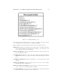
6.2 Requirements . . . . . . . . . . . . . . . . . .
6.2.1 Functional requirements . . . . . . . .
6.2.2 Non-functional requirements . . . . .
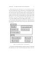
6.3 Structure and Functionality . . . . . . . . . .
6.4 Schema of the application . . . . . . . . . . .
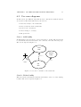
6.5 Use cases diagrams . . . . . . . . . . . . . . .
6.6 Design of the network . . . . . . . . . . . . .
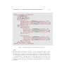
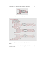
6.6.1 IM protocol . . . . . . . . . . . . . . .
6.7 Analysis of the application . . . . . . . . . . .
6.7.1 Data-flow diagrams . . . . . . . . . . .
6.7.1.1 Level 0 . . . . . . . . . . . .
6.7.1.2 Level 1 . . . . . . . . . . . .
6.7.1.3 Level 2 . . . . . . . . . . . .
6.7.2 States Diagrams . . . . . . . . . . . .
6.8 Design and implementation of the application
6.8.1 Design decisions . . . . . . . . . . . .
6.8.1.1 Data Model and Storage . .
6.8.1.2 Objects . . . . . . . . . . . .
6.8.2 Design of the Graphical User Interface
6.8.2.1 Windows hierarchy . . . . .
6.8.2.2 Windows Prototypes . . . .
6.8.3 Implementation . . . . . . . . . . . . .
6.9 Functional tests . . . . . . . . . . . . . . . . .
6.9.1 Network tests . . . . . . . . . . . . . .
6.9.2 Application tests . . . . . . . . . . . .
6.10 Summary . . . . . . . . . . . . . . . . . . . .
.
.
.
.
.
.
.
.
.
.
.
.
.
.
.
.
.
.
.
.
.
.
.
.
.
.
.
.
.
.
.
.
.
.
.
.
.
.
.
.
.
.
.
.
.
.
.
.
.
.
.
.
.
.
.
.
.
.
.
.
.
.
.
.
.
.
.
.
.
.
.
.
.
.
.
.
.
.
.
.
.
.
.
.
.
.
.
.
.
.
.
.
.
.
.
.
.
.
.
.
.
.
.
.
.
.
.
.
.
.
.
.
.
.
.
.
.
.
.
.
.
.
.
.
.
.
.
.
.
.
.
.
.
.
.
.
.
.
.
.
.
.
.
.
.
.
.
.
.
.
.
.
.
.
.
.
.
.
.
.
.
.
.
.
.
.
.
.
.
.
.
.
.
.
.
.
.
.
.
.
.
.
.
.
.
.
.
.
.
.
.
.
.
.
.
.
.
.
.
.
.
.
.
.
.
.
.
.
.
.
.
.
.
.
.
.
.
.
.
.
.
.
.
.
.
.
.
.
.
.
.
.
.
.
.
.
.
.
.
.
.
.
.
.
.
.
.
.
.
.
.
.
.
.
.
.
.
.
.
.
.
.
.
.
.
.
.
.
.
.
62
. 62
. 63
. 63
. 63
. 64
. 64
. 66
. 68
. 70
. 75
. 75
. 76
. 76
. 77
. 78
. 82
. 82
. 82
. 86
. 91
. 92
. 93
. 99
. 99
. 99
. 100
. 101
4
CONTENTS
7 Applying Evaluation Framework
7.1 Introduction . . . . . . . . . . . . . . . .
7.2 Simulator design . . . . . . . . . . . . .
7.3 Performance Evaluation . . . . . . . . .
7.3.1 Experiment 1 (Routing Hops) . .
7.3.2 Experiment 2 (Load Balance) . .
7.3.3 Experiment 3 (Recovery Time) .
7.3.4 Experiment 4 (Join Time) . . . .
7.3.5 Experiment 5 (Leave Time) . . .
7.3.6 Experiment 6 (Latency) . . . . .
7.3.7 Experiment 7 (Real Conditions)
7.4 Summary . . . . . . . . . . . . . . . . .
.
.
.
.
.
.
.
.
.
.
.
.
.
.
.
.
.
.
.
.
.
.
.
.
.
.
.
.
.
.
.
.
.
.
.
.
.
.
.
.
.
.
.
.
.
.
.
.
.
.
.
.
.
.
.
.
.
.
.
.
.
.
.
.
.
.
.
.
.
.
.
.
.
.
.
.
.
.
.
.
.
.
.
.
.
.
.
.
.
.
.
.
.
.
.
.
.
.
.
.
.
.
.
.
.
.
.
.
.
.
.
.
.
.
.
.
.
.
.
.
.
.
.
.
.
.
.
.
.
.
.
.
.
.
.
.
.
.
.
.
.
.
.
.
.
.
.
.
.
.
.
.
.
.
103
103
104
105
105
106
107
108
108
108
109
109
8 Conclusions
110
9 Future Work
111
A Acronyms
116
B Javadoc Documentation
117
List of Figures
5.1
5.2
5.3
5.4
5.5
5.6
5.7
5.8
51
53
55
56
57
57
58
5.9
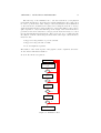
Evaluation flow. . . . . . . . . . . . . . . . . . . . . . . . . . . . .
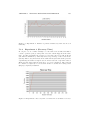
Benchmark 1: Routing hops. . . . . . . . . . . . . . . . . . . . .
Benchmark 2: Load balance. . . . . . . . . . . . . . . . . . . . .
Benchmark 3: Time recovery after a massive fail. . . . . . . . . .
Benchmark 4: Average join time of a single node. . . . . . . . . .
Benchmark 5: Average leave time of a single node. . . . . . . . .
Benchmark 6: Latency of the messages. . . . . . . . . . . . . . .
Benchmark 7: Tries to simulate real underlying physical network.
Continue in next figure. . . . . . . . . . . . . . . . . . . . . . . .
Continuation of benchmark number 7. . . . . . . . . . . . . . . .
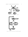
6.1
6.2
6.3
6.4
6.5
6.6
6.7
6.8
6.9
6.10
6.11
6.12
6.13
6.14
6.15
6.16
6.17
6.18
6.19
6.20
6.21
6.22
6.23
6.24
6.25
6.26
6.27
Schema of the application. . . . . . . . . . . . . . . . . . . . . . .
Use case a: Add user to the buddie list. . . . . . . . . . . . . . .
Use case b: Delete user from the buddie list. . . . . . . . . . . . .
Use case c: Conversation with another user. . . . . . . . . . . . .
Use case d: Edit user preferences. . . . . . . . . . . . . . . . . . .
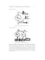
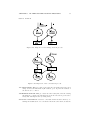
Network with eight nodes and successors. . . . . . . . . . . . . .
Network with eight nodes, showing the exponential pointers. . . .
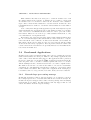
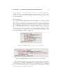
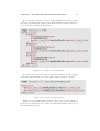
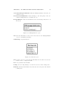
XML message to ask for successors. . . . . . . . . . . . . . . . . .
XML message to reply with the successors. . . . . . . . . . . . .
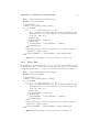
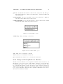
XML message to join the network. . . . . . . . . . . . . . . . . .
XML message to reply a join petition. . . . . . . . . . . . . . . .
XML message to made a lookup. . . . . . . . . . . . . . . . . . .
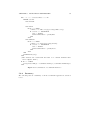
XML message to reply a lookup message. . . . . . . . . . . . . .
XML message to create a new conversation. . . . . . . . . . . . .
XML message to reply to the source of a conversation. . . . . . .
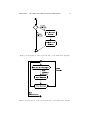
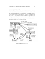
Elements used in the data flow diagrams. . . . . . . . . . . . . .
Data Flow diagram of level 0. . . . . . . . . . . . . . . . . . . . .
Data flow diagram of level 1. . . . . . . . . . . . . . . . . . . . .
Explosion of the manage network process. . . . . . . . . . . . . .
Explosion of the conversation process. . . . . . . . . . . . . . . .
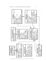
Main states diagram of the application. . . . . . . . . . . . . . .
Description of the idle state of the main states diagram. . . . . .
Description of the add buddie state of the main states diagram. .
Description of the del buddie state of the main states diagram. .
Description of the conversation state of the main states diagram.
Content of the preferences file. . . . . . . . . . . . . . . . . . . .
Content of the buddie list file. . . . . . . . . . . . . . . . . . . . .
65
66
67
67
68
69
69
70
71
72
72
73
73
74
74
75
76
76
77
77
79
79
80
81
81
82
83
5
59
60
6
LIST OF FIGURES
6.28
6.29
6.30
6.31
6.32
6.33
6.34
6.35
6.36
6.37
6.38
6.39
6.40
6.41
6.42
6.43
6.44
6.45
6.46
6.47
6.48
6.49
Content of the key pair file. . . . . . . . . . . . . . . . .
Classes designed to store the data and its dependences.
Package structure of the information. . . . . . . . . . . .
BuddieMaintainer and NetworkMaintainer objects. . . .
NetworkNode object. . . . . . . . . . . . . . . . . . . . .
NodeTable object. . . . . . . . . . . . . . . . . . . . . .
Lookup object. . . . . . . . . . . . . . . . . . . . . . . .
MessageHandler object. . . . . . . . . . . . . . . . . . .
MessageListener object. . . . . . . . . . . . . . . . . . .
Network object. . . . . . . . . . . . . . . . . . . . . . . .
Buddie object. . . . . . . . . . . . . . . . . . . . . . . .
Preferences object. . . . . . . . . . . . . . . . . . . . . .
BuddieList object. . . . . . . . . . . . . . . . . . . . . .
Conversation object. . . . . . . . . . . . . . . . . . . . .
ConversationList object. . . . . . . . . . . . . . . . . . .
Windows hierarchy tree. . . . . . . . . . . . . . . . . . .
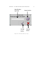
Main window prototype. . . . . . . . . . . . . . . . . . .
Add buddie window prototype. . . . . . . . . . . . . . .
Preferences window. . . . . . . . . . . . . . . . . . . . .
Open window. . . . . . . . . . . . . . . . . . . . . . . . .
Save window. . . . . . . . . . . . . . . . . . . . . . . . .
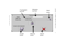
Conversation window. . . . . . . . . . . . . . . . . . . .
.
.
.
.
.
.
.
.
.
.
.
.
.
.
.
.
.
.
.
.
.
.
83
84
85
86
86
87
87
88
89
89
90
90
90
91
91
92
93
94
95
96
97
98
7.1
7.2
Experiment 1: Routing hops vs the number of nodes. . . . . . . .
Experiment 2: Number of packets forwarded per unit time on
average vs number of nodes. . . . . . . . . . . . . . . . . . . . . .
Experiment 2: Number of packets forwarded by 20 nodes choosen
randomly. . . . . . . . . . . . . . . . . . . . . . . . . . . . . . . .
Experiment 3: Recovery time of a random node vs number of
nodes. . . . . . . . . . . . . . . . . . . . . . . . . . . . . . . . . .
Experiment 4: Average join time vs number of nodes. . . . . . .
Experiment 7: Average number of hops vs number of nodes. . . .
106
7.3
7.4
7.5
7.6
.
.
.
.
.
.
.
.
.
.
.
.
.
.
.
.
.
.
.
.
.
.
.
.
.
.
.
.
.
.
.
.
.
.
.
.
.
.
.
.
.
.
.
.
.
.
.
.
.
.
.
.
.
.
.
.
.
.
.
.
.
.
.
.
.
.
.
.
.
.
.
.
.
.
.
.
.
.
.
.
.
.
.
.
.
.
.
.
106
107
107
108
109
List of Tables
2.1
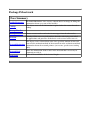
Characteristics summary. . . . . . . . . . . . . . . . . . . . . . .
30
5.1
Benchmark applications. . . . . . . . . . . . . . . . . . . . . . . .
61
6.1
6.2
Functional requirements. . . . . . . . . . . . . . . . . . . . . . . .
Non-functional requirements. . . . . . . . . . . . . . . . . . . . .
63
64
7
Chapter 1
Introduction
1.1
Definition
There are several definitions of peer-to-peer network depending on where you
look for it, for example:
“Generally, a peer-to-peer (or P2P) computer network is any network
that does not have fixed clients and servers, but a number of peer
nodes that function as both clients and servers to the other nodes on
the network. This model of network arrangement is contrasted with
the client-server model. Any node is able to initiate or complete any
supported transaction. Peer nodes may differ in local configuration,
processing speed, network bandwidth, and storage quantity”[42].
“Peer-to-Peer is a class of applications that takes advantage of resources storage, cycles, content, human presence available at the
edges of Internet. Because accessing these decentralized resources
means operating in an environment of unstable connectivity and unpredictable IP addresses, peer-to-peer nodes should operate outside
the DNS and have significant or total autonomy of central servers”[43].
“Does the system give the nodes at the edges of the network significant autonomy? Does the system allow for variable connectivity and
temporary network addresses? If the answer is yes, then the application is peer-to-peer, else it is not” Clay Shirkey (Accelerator Group).
Based on this definitions, and the characteristics of this kind of networks described in some other documents our definition of peer-to-peer networks could
be written as the following: A distributed network architecture may be called
a peer-to-peer network, if the participants share a part of their own resources
(processing power, storage capacity, network capacity, ...). The participating
applications should be equal among them in order to be classified as peer-to-peer,
equality of resources, responsibilities and functionality. In order to distinguish
between peer-to-peer and grid computing we should talk about dynamicity of
the network nodes. Peer-to-Peer nodes are supposed to be very dynamic and
can leave the network at any moment, they work only in their profit, while grid
computing network nodes use to be available for long periods of time and work
for the profit of the group.
8
CHAPTER 1. INTRODUCTION
1.2
9
History
Peer-to-Peer is not a new phenomenon, applications like the Domain Name
Server acts in a Peer-to-Peer way since the beginnings of the Internet. If we talk
about mainstream P2P it starts in 1999, when the first file sharing P2P client
appears (Napster) and reached popularity within few months. This popularity
has been growing since then and now P2P file sharing is one of the fundamentals
Internet services. Since 1999 there has been three generations [2] of P2P file
sharing:
First Generation: May 1999 saw the launch of Napster [53], it started to
become so popular that the music industry commenced proceedings to
force the closure of Napster. This happened in late 2001 and could be
largely attributed to the topology of Napster infrastructure. Napster was
based around centralized index servers that maintained a database with
all the contents of the network and clients logged on at any time. This
infrastructure has clearly a single point of failure and is difficult to scale.
Second Generation: March 2000 saw the publication on Slashdot of an article
by Nullsoft [54] that divulged the secrets of an “open source Napster”
protocol. Nullsoft is a division of AOL, and by the time AOL removed
the article, the protocol was extended all over Internet. This was the
start of the Gnutella protocol, where their authors removed the necessity
of a central index server and created a distributed architecture that were
easy to maintain and impossible to close by an authority. Despite of
being workable, this architecture shows that it generates large volumes of
network traffic and slow search performance.
Third Generation: Realizing the problems of the Gnutella architecture lead
to the development of a number of hybrid solutions which combined the
benefits of a centralized topology with the stealth of the distributed one.
This hybrid solution introduced a hierarchical design that deployed a virtual network of supernodes, which assisted in reducing the amount of
search traffic on the network and helped to improve the perceived speed
of file searches. This generation was lead by client Kazaa [55] and its
Fasttrack network.
1.3
Types of Peer-to-Peer Network Architectures
This section looks at the different types of architectures where the peer-to-peer
systems could be classified. These types could be associated more or less with the
different generations of peer-to-peer systems described above, but applications
of all the types are developed nowadays instead of only the ones belonging to
the last generation. The following are the types of our classification:
Centralized P2P networks: one basic service, like search or distribution of
IDs, is made by a central server that becomes this way a single point of
failure. I.E: Napster.
Distributed P2P networks: all peers are equal, and every peer could leave
the network without degrading the QoS of the network. There are two
main types:
CHAPTER 1. INTRODUCTION
10
Unstructured P2P networks: the connections of the network peer are
not defined anyway and can make unbalanced graphs. I.E: Gnutella.
Structured P2P networks: All the peers of the network have the same
connections and the graph is well defined from the beginning. I.E:
Chord.
“Hybrid” networks: a mixed architecture between the centralized and distributed networks, they try to obtain the profits of both worlds without
any of their disadvantages. I.E: Fasttrack.
1.4
Services Provided by Overlay Networks
One of the main services provided by an overlay network is a lookup service,
e.g. the location of values based on a key. Each key is dynamically mapped
to a unique live node, called the key’s root. To deliver messages efficiently to
the root, each node maintains a routing table consisting of the identifiers of the
nodes and the IP addresses associated with them. Messages are forwarded across
overlay links to nodes whose identifiers are progressively closer to the keys in
the identifier space. But every different network implements this idea in its own
way with subtly distinct semantics that made the network more appropriate
for some applications than others, the main ideas are described in the following
lines:
DHT(Distributed Hash Table): provides the same functionality as a traditional hash table, by storing the mapping between a key and a value.
This service implements a simple store and retrieve functionality, where
the value is always stored at the live overlay node(s) to which the key is
mapped by the routing algorithm. Examples of this service could be a
Distributed File System or a Distributed Database.
DOLR(Decentralized Object Location and Routing): provides a decentralized directory service. Each object replica (or endpoint) has an objectID and may be placed anywhere within the system. Applications
announce the presence of endpoints by publishing their locations. A
client message addressed with a particular objectID will be delivered to a
“nearby”endpoint with this name. Examples of this service are file sharing
and distributed services like naming.
Group Anycast/Multicast: provides scalable group communication and coordination. Overlay nodes may join or live a group, multicast messages
to the group or anycast messages to a member of the group. Examples of
this service could be distributed instant messaging and publish / subscribe
message service.
1.5
Properties of Peer-to-Peer Networks
When designing a new overlay network we should think first about the different
characteristics that should be achieved to effectively build a worthy network.
These are the properties that we have to bear in mind when we are designing a
peer-to-peer network [1]:
CHAPTER 1. INTRODUCTION
11
Software and Hardware Heterogeneity: nodes that belongs to a P2P have
no type of hardware imposed by the system. This way the system should
be able to run in a very big range of hardware and software combinations.
Scalability: the network should try to have the same performance whether
it has 10 or 10000000 of nodes. It is important then that the speed of
operations and need of resources could be as independent of number of
nodes as possible.
Dynamicity of Nodes and Resources: by definition, the nodes of a P2P
network could join and leave whenever they want, so none of the nodes
could have a main role on its own, all the operations should be done by
the whole network.
Maintainability: nodes could join and leave the network constantly, so the
network should adapt its structures as fast as possible after one of this
events in order to not lose any kind of QoS.
Load Balancing: for the network to maintain QoS, is important to distribute
the load of the operations as much as possible, this way as many nodes
are involved in made an operation, less load (network, storage, ...) will be
in every node.
Fault Tolerance: due to the dynamicity of nodes and resources, is important
for the network to have good algorithms to maintain the quality of service
even when there are a large number of fails across the network. This could
include replications, fault tolerant routing tables, ...
Security and Anonymity: As an extra characteristic, this two could try to
be achieved. We should think that we are in an untrusted network where
we don’t know the other peers, and they could try to harm our system.
Trust: as we don’t know the other peers, is also desirable to know that the
contents we obtain from the network as “trustable” as possible. This characteristic is difficult to achieve because it fights against the one before.
We should try to find a balance between these two desirable characteristics.
1.6
Trade-offs
Since it is not possible to build a perfect network suitable for all possible uses
because the different necessities of the diverse networks often confront ones
against the others, we should choose the best possible balance of the different
characteristics in order to meet our requirements. In this section some of the
design trade-offs will be exposed:
Routing Table Size VS Lookup Length: Even if it is possible to have a lineal lookup speed, this won’t be very practical because we should store the
information of all the other participants in the network. Even if nowadays
the memory storage is quite affordable, the peer-to-peer networks used
currently have too much nodes to think about storing all the information.
On the other hand, with storing only the information about one node of
the network, if it is well chosen, could made a network able to forward the
CHAPTER 1. INTRODUCTION
12
messages to its destination, but the length of the lookups will make the
network also unusable. We should choose a routing table size that made
both characteristics have the best possible values depending on the characteristics of the applications and the users. For example, if all our user
are portable devices like PDAs the routing table should be smaller than
the ones used on normal workstations, and some applications like instant
messaging systems need faster responses that others like web storage.
Anonymity VS Trust: These two characteristics are not the main ones in an
overlay network, but in the future after the other main problems will be
solved, these ones will become the main ones. In addition, some applications and some environments will need anonymity (censored environments) as well as trust (communications applications). Both issues are
clearly one against the other because by definition anonymous users could
not be trusted only by themselves. To find a special method that could
allow both of them could be very difficult, and maybe the easiest way of
choosing between them is depending on the characteristics of our applications, give preference to the one that is more beneficial to our system.
Fault Tolerance VS Routing Information: Due to the dynamicity of the
nodes in peer-to-peer systems, some fault tolerance should be added to the
system. This tolerance is normally accomplished by adding information
about more nodes of the system in order to have different paths to reach
an arbitrary node in the network. As in the first trade-off, we could have a
perfectly tolerant system by storing information about all the nodes, but
also as in the first one this is not possible nowadays. We should think to
add more tolerance depending on the environment that is being to hold the
system, in more unstable environments like mobile ones, should be bigger
than in the ones using workstations with stable network connections.
Scalability VS Routing Table Size: This trade-off is closely related to the
first one, if the lookup length increases very fast as we add new nodes to
the system, then the scalability won’t be as good as should be desired,
but it is possible that among our desired network characteristics is not to
have a big amount of nodes. We should also balance this issue in order to
made the most adjusted design to our necessities.
1.7
Design Issues
Some issues have to be solved while an overlay network is designed. First of all
we should define where we are going to classify our network based on its topology.
We could design our network with some centralized services such as Napster,
totally decentralized or mix characteristic from both previous approaches. If
we choose the network to be totally decentralized, it should be also put in the
structured or unstructured group depending on the way the nodes interact with
the others. Once done that, we should define the topology itself, some network
acts like a ring of nodes, some others like a tree, ...
It should be also defined the way the communication protocols act. Several
operations and actions seem to be the main ones within this kind of network,
we should define how the network will accomplish these tasks. The network
CHAPTER 1. INTRODUCTION
13
should be at least able to let the nodes join and leave it, let the nodes search
for network objects and fails should be properly managed in the network. All
these actions should be performed with correction, that is, the network nodes
should act as is defined in the specification of the network.
The information that every node is going to store should be also defined, this
information could be classified in two groups: objects and status information.
The design of the network should clearly show where the objects that the nodes
introduce to the network are going to be stored. The status information is that
which is required in order to route messages and in node interaction.
The network should also be defined bearing in mind the characteristics mentioned before. If we can, as we have said some of the characteristics have interactions between them, all of them should try to be achieved, that is, our should
be as scalable and load balanced as possible and so on. In order to choose between some characteristics that could be troubled, the final goal of the network
should be used.
1.8
Problem Definition and Expected Results
The major goal of this project is developing and demonstrating a general evaluation strategy for evaluation of P2P overlay networks, and a suggested set of
benchmark applications that can be used for evaluation. In this document we
intend to study the following aspects:
• Approaches to overlay networks, their functionality, characteristics and
taxonomies.
• Design issues to be considered for developing unstructured and structured,
general and application-specific overlay peer-to-peer networks.
• Applications in structured overlay networks and application requirements.
• Evaluation mechanisms, experimental methodologies and benchmark applications used to evaluate overlay networks.
The first part of the thesis consist of a literature study of the current state of
art in this field that ends up with the following surveys:
• A survey of existing approaches to unstructured and structured general
and application-specific overlay peer-to-peer networks. This survey should
result at a proposal for a set of parameters and features of networks that
can be used for their description and classification (taxonomy).
• A survey of existing application domains for structured P2P overlay networks and those requirements that an application exposes to the overlay
network.
• A survey of existing mechanisms and benchmark applications used to evaluate P2P networks.
The second part will be the development of an evaluation strategy that could be
applied to overlay networks and that include an experimental methodology and
a set of benchmarks algorithms. In order to demonstrate the design principles
CHAPTER 1. INTRODUCTION
14
studied in the literature study, a prototype of an application specific overlay
network will be shown in the third part of the document. Finally, the evaluation
framework will be tested using the network previously built.
1.9
Structure of the Thesis
The rest of the thesis is structured as follows. Chapter 2 gives an overview of
overlay networks studied in this thesis in order to determine and illustrate different approaches to peer-to-peer network architectures and common and specific properties of different structured peer-to-peer networks recently proposed
and developed. The overview helps to define requirements to the network and
a common evaluation framework for P2P networks. Chapter 3 describes how
multicast is implemented done in different overlay networks studied. Chapter 4
describes several applications developed based on the previous networks, helping in find the different possibilities where the peer-to-peer networks could be
applied. Chapter 5 describes a common evaluation framework for overlay network which could be used to compare several networks to find the strong and
weak points of everyone. Chapter 6 details the design and implementation of an
example of peer-to-peer application (an instant messaging system in this case)
that will be used later to check our evaluation framework. Chapter 7 applies
the evaluation framework described in chapter 5 to the application developed in
the previous chapter trying to show whether the application is usable or not in
a real environment. Finally chapters 8 and 9 show the conclusions and results of
the thesis and the possible future work that could be done in order to enhance
the results of the thesis.
Chapter 2
Overlay Networks
“Magic is real ... unless declared integer”
2.1
Introduction
During this chapter different overlay networks will be observed trying to point
out their main features in order to determine design issues that need to be considered when developing an overlay network; and to define a common evaluation
framework for overlay networks. All the networks described later belongs to the
pure peer-to-peer networks which are the main target of this thesis. These
networks have been selected by being clear and important examples on their
respective types. The next paragraph will show all the different case studies
and after classify them within the classification exposed in section 1.3, they will
be shortly described.
Unstructured P2P networks:
Gnutella [3]: A P2P network in which a node tries to search the network
by flooding neighbors with search messages. This way if every node
have an small amount of neighbors, the message has a big probability
to reach the destination node. The routing information is very small,
but the use of the network resources are not very good either.
Freenet [4]: Extra features like publisher anonymity and security, and
resistance to attacks were borne in mind when this network was designed. The network could not be in theory controlled by anyone.
These network is described as an example of the extra characteristics
that will be demanded to the networks in the future.
Structured P2P networks:
CAN (Content Addressable Network) [5]: DHT that uses a n-dimensional
space, division in zones and pointers to neighbors to search objects.
Chord [6]: DHT that uses a circular one-dimensional space and a set of
special neighbors to search objects.
Pastry [7]: DHT based on trees of neighbors with different levels and a
circular space like Chord based on numerically closest nodes.
15
CHAPTER 2. OVERLAY NETWORKS
16
Tapestry [8]: DOLR with routing like Pastry, but instead of using numerically closest uses next higher digit at each loop.
DKS (N, k, f ) [9]: Generalization of the Chord network but it does not
use active correction of tables when a node fails.
2.2
Gnutella
In this section the Gnutella protocol is described [10]. The protocol was proposed as a file sharing protocol. It is based on maintaining TCP connections to
a number of other Gnutella hosts. Gnutella hosts are called servents. When a
servent wants to join the network, it first has to obtain the IP address and port
of another servent, when a servent receive this message can elect between reply
to it accepting the connection or simply ignore it. Once a servent has a table of
neighbors it can prove the neighbors by sending PING messages to them, they
will respond with a PONG message that contains its address (or maybe another
servent address) and the quantity of data shared.
2.2.1
Search
When a servent wants to make a search, it sends a QUERY message to all of
its neighbors, which broadcast the message to its own neighbors. In order to
not overload the network, every message has a TTL which is decremented in
every hop, when it becomes 0, the message is not broadcasted anymore. When a
servent receives a QUERY message reply with a QUERYHIT message if has any
file that matches the QUERY message keywords. The QUERYHIT messages are
sent to the QUERY source across the same path that the QUERY message used.
In order a firewalled to be able to contribute to the network, PUSH messages
can be used (that should use the same path as the QUERYHIT message).
2.2.2
Download
The protocol used to download a file is HTTP. When a servent wants to download a file from other servent, simply creates a HTTP connection with it. If this
is not possible, because the file source servent is firewalled, a PUSH message is
sent, and the connection is established by the file source servent.
2.2.3
0.6 Version Extensions
Some other extensions has been made in the Gnutella project [10] in order to
made it a more modern peer-to-peer network. Bye messages are sent when a
node leaves the network. In addition, in order to reduce the network overhead
caused by the initial protocol, there have been introduced higher level nodes
called ultrapeers. This nodes maintains a high number of connections with normal nodes (leaf nodes), and some connections with other ultrapeers. Ultrapeers
communicate with other ultrapeers in the same way that peers communicate in
the 0.4 protocol. Ultrapeers shields leaf nodes from most of the traffic using one
of his two approaches:
• Creating an index of the files shared by all its leaf nodes. It’s made by
periodically sending index query messages to the peers.
CHAPTER 2. OVERLAY NETWORKS
17
• Using a bit vector (based on a hash table) that stores which keywords
cause a query hit in which leaves.
2.2.4
Implementations
As Gnutella is designed as a file sharing network, the current implementations of
the protocol are file sharing programs. There are quite a lot of these programs
available for many platforms (Windows, Linux, Mac), most of them are free
software. Some of these programs are Limewire, Phex, Morpheus, BearShare,
Qtella, Gnucleus, Gtk-gnutella. In order to find the neighbors which are necessary to connect to the network, these programs ask some particular servers to
find some other client that could be closer to them.
2.3
Freenet
This section describes the Freenet protocol [4]. Freenet was developed and
created with additional goals to file location:
• To provide publisher anonymity and security;
• Resistance to attacks: a third party shouldn’t be able to deny the access
to a particular file, even if it compromises a large fraction of machines.
2.3.1
Architecture
Each file is identified by an unique identifier based on the hash of its name.
Each machine stores a set of files, and maintains a “routing table” to route the
individual requests. This routing table contains three fields:
Id: identification of the file in the network.
Next hop: another host that could possibly stores the file.
File: identification of the file if it’s stored on the local machine.
2.3.2
Query
When a node sends a query message, it sends it to the next hop of the closest
id to the file identifier in the “routing table”. When a node receive a query:
• If it’s in the local machine, stops the forwarding of the message.
• If not, search for the closest id in the “routing table”, and forward the
message to the next hop.
Every query has a TTL that is decremented in every hop, to obscure the message
originator:
• TTL can be initialized to a random value within some bounds.
• When TTL=1 the query is forwarded with a finite probability.
Each node maintains the state for all queries that have traversed it in order to
avoid cycles. When file is returned, it’s cached along the reverse path with a
finite probability.
CHAPTER 2. OVERLAY NETWORKS
2.3.3
18
Insertion
The insertion is made in two steps:
• Search for the file to be inserted, this is made by sending an special request
where the TTL means the number of copies to be made. It goes throw
the path and made an entry in the “routing table” of all the nodes that
forward the query. If one node finds that the id of this file exists within
its table, it sends a message back to the source.
• If there is no hit in the search described above, then the file is sent through
the same path, and every node that forwards the message stores a copy
of the file. Every node in the path can arbitrary replace the source of the
query with itself in order to obscure the true originator.
2.3.4
Data Management
When a node gets out of space, it simply deletes the less recently used file to
make space for a new one. In order to deny the ownership of a file by any node
in the network, all files are encrypted with the goal of the node operator didn’t
know the contents of the file. When a node joins the network, its id is generated
by the XOR of some seeds generated in the same way as the insert works. When
a node search for a file, this is not always found (this happens also in Gnutella)
because of the TTL.
2.3.5
Implementations
An implementation for the Freenet network, and the Freenet network protocol is
available for download at its website [56]. A Java program with a web interface
is used to retrieve files from the network. This application is only oriented to
retrieve files using a key. No search capabilities exists, and the key of every
document should be found using other methods such as direct communication
with the author or publication via web. This seems to conflict with the idea of
anonymity that the authors want to give to their network. When big files are
inserted in the network, this application split the file in several blocks and adds
redundancy in order to reconstruct the file if some of the blocks are lost.
2.4
CAN (Content Addressable Network)
In this section the CAN protocol is described [5]. The basic operations performed at CAN are insertion, lookup and deletion of (key, value) pairs. Each
CAN node stores a zone of the entire hash table. The hash table is a virtual
d-dimensional Cartesian coordinate space on a d-torus, that is, the last point of
the space is followed by the first one, it is a circular space. At any point of time
the entire space is divided dynamically among all nodes. A node learns and
stores the IP addresses of the nodes that hold a zone adjoining its own zone.
With this neighbors, every node can route a message to every other node. To
store a key, this key is deterministically mapped to the space by a hash function,
the pair is then stored at the node that owns the zone where the key has been
mapped. To retrieve the key every node can apply the same hash function and
route a message to the owner.
CHAPTER 2. OVERLAY NETWORKS
2.4.1
19
Node Arrivals
As we have said, the entire space is divided among the nodes currently in the
system. This partitioning is performed by dividing an existing zone in two halves
every time a node joins the network. The split is done following a well known
ordering of the dimensions, so both halves can be merged again when a node
leaves the network. We can think of the zones as a partition tree where every
node owns a leaf. If we think in binary spaces, every node is assigned with a
binary identifier that represents its place on the partition tree. When a new
node try to join the network has to perform the following steps:
1. It should find the address of an arbitrary node.
2. It must find the node that is going to share its zone using the routing
mechanism provided by CAN. This is made by choosing an arbitrary point
and routing a join message to it. When it reaches the destination, the node
that holds the zone compares it with its neighbors and the bigger zone is
the one that is going to be split. It exchanges neighbors and pairs of
value-key with the new node and then split its zone in two halves, one of
them will be given to the new node.
3. Neighbors must be notified so they can update their routing tables. The
nodes send a first update message, and periodically refreshes.
2.4.2
Routing
CAN routing works by simply routing the straight path between the start point
and the end point in the coordinate space. Every node forward a message by
simply routing it to the neighbor whose coordinates are closest
to the end point.
1
In a d-dimensional space the path length will be θ n( d ) . As more than one
path exists between two points, a node could route the message even if some of
its neighbors crashes. If one of the nodes can’t make progress in one direction,
asks its neighbors if they can make progress and send the message to one of the
neighbors that can make any progress.
2.4.3
Node Departures
The normal procedure for a node to leave the network is to give its zone state
(id and neighbors) and pairs of key-value owned by the node to another node
called takeover node. If the takeover node zone can be merged with this zone to
made a new valid zone, this is made; and if it is not possible, then the takeover
node will handle both zones till it is possible to merge zones.
When a node crashes, the takeover node and the neighbors work together to
rebuild the structures, but all the pairs stored on the crashed node are lost and
the information need to be rebuilt. There are some alternatives to rebuilt these
data, the first one is that the owners of the data refresh it, and the second one
is to make more than one copy of the data in other nodes. Recovery process is
made in the following phases:
1. Identification of the takeover node: This could be easily done using the
partition tree. If the sibling of the node that has crashed is a leaf, then
CHAPTER 2. OVERLAY NETWORKS
20
both nodes can be merged into a new valid zone. If not a depth-first search
is made to find the takeover node, both zones cannot be merged into one
and the takeover node handles them till some new node contacts to join
the network or the other neighbors leave the network.
2. Restore neighbor links: When a node realizes that one of its neighbors has
die (because an absence of refreshing messages), it sends a message looking
for the takeover node that is routed using ids instead of coordinates. All
these messages end in the numerically closest node that is the takeover
node. This way the takeover node knows all its neighbors and can rebuild
the zone.
2.4.4
Evaluation
For simulation of the CAN algorithm, the Transit Stub (TS) topologies are used
with the GT-ITM topology generator [17]. TS topologies model networks using
a 2-level hierarchy of routing domains with transit domains which interconnect
lower level stub domains.
Several parameters could be changed in the simulation, some of them are
dimension, realities (more than one CAN could connect all the nodes in order
to improve reliability and fault tolerance), number of nodes, number of nodes
that are in charge of a determined zone. The number of nodes parameter range
starts at 256 nodes and end at 1 million of nodes.
The main output metric is the number of routing hops per message. In order
to better reflect the underlying IP topology, every hop could be weighted with
the RTT (Round Time Trip). Another output parameter used is the perceived
user latency, with this measure the time since the query is sent till the response
arrives is sized. Other parameters (which are more difficult to measure) such as
availability , load balance and fault tolerance are also borne in mind.
The first set of tests is made without any node failure. As this is not realistic
for a peer-to-peer network (we should assume that nodes are always failing and
joining and leaving the system) another set of tests is made with the inclusion of
this fails. For the making of these tests, a fixed window of time is selected, and
increasing number of nodes fails during this time. The extra amount of traffic
generated because of the recovery algorithms is measured. The node failure rate
starts at 10% and goes to 50% of the total number of nodes.
2.4.5
Implementations
There is not any implementation of the CAN network available nowadays. Only
a simulator of the CAN network developed for evaluation of the network has
been found.
2.5
Chord
In this section the Chord protocol is described [6]. Chord is a distributed hash
table that only provides one operation: it maps a given key to a node that
stores the value associated with this key (IP = lookup(key)). Nodes identifiers
are choosing by hashing the node IP address, while a key identifier is obtained
by hashing the key. The identifier length (m) should be long enough to make
CHAPTER 2. OVERLAY NETWORKS
21
the possibility of id collision almost impossible. Identifiers are ordered in an
identifier circle modulo 2m . A key k is assigned to the first node that id is equal
or greater to its own identifier (both identifiers are in the same range). This
node is called successor node of k.
2.5.1
Lookup
Each node maintains its successor in the id circle, this way we can assume that
every key is found simply by going along the circle through the successors. For
increasing the speed of searches each node maintains a table with m nodes,
where m is the number of bits of an id. The i-th entry on the table contains
the first node that succeeds the node by at least 2(i−1) , this pattern give every
node more information about keys that are closer to it. With these entries the
number of hops is θ (log N ).
2.5.2
Join
When a node n wants to join the network, it first need to know one node n’. This
node is used to mad a lookup of its own identifier n, this way the node discover
its successor. Periodically every node asks its successor about its predecessor.
In this way, our new node n could check if there is a better successor for it
and the successor can change predecessor if necessary. After that our new node
asks it successor to share the keys that are distributed between both nodes and
construct the table of fingers doing lookups for all of them. Once this cycle
finished, the network is stable till next joins.
2.5.3
Failures
To deal with node failures, each node not only stores its successor but a list of
successor in order to be more difficult to break the routing algorithm. Only if
all of these successors fail simultaneously the algorithm could fail in a lookup.
If only a part of this successors die, it can still route messages and rebuild the
finger table in order to become a stable network.
2.5.4
Leave
A voluntary leave could be treated as a node failure, but two enhancements can
be made to improve Chord performance when a node leaves:
• The node which leaves, can transfer its keys to its successor before leaving.
• The node could inform its successor and predecessor to change their successors and predecessor with the ones from the node which leaves list.
2.5.5
Evaluation
A simulation is also made in the evaluation of Chord. Input parameters are
the number of nodes which range starts from 100000 and ends in 1000000. The
number of keys in the system is fixed to 5×10⁵ . Virtual nodes are also used here,
and is another input parameter that can be changed in order to achieve some
desirable properties such as load balance. As a result of increasing the number
CHAPTER 2. OVERLAY NETWORKS
22
of virtual nodes per physical node, the size of the routing tables increases also.
Also here, the main output measure used to size the performance of the system
is the path length that a message has to travel through its destiny. Number of
lookups failures when a number of nodes fails is also sized and the stabilization
algorithms are also measured .
In order to better evaluate the network, an Internet protocol has been developed to obtain some latency measures. The Chord nodes are ten sites on a
subset of the RON test-bed in the United States [18]. Nodes are situated in
California, Colorado, Massachusetts, New York, North Carolina and Pennsylvania. Experiments with a number of nodes larger than ten are conducted running
more than one instance of Chord in every site.
2.5.6
Implementations
There are two implementations of Chord available nowadays in the project website [11]. One of it is a simulator that does not depend on any library. The other
one is a library, which implements the lookup function described above, written
in C++. On top of this library a complete distributed hashtable available also
as a library exists (DHash). The implementation is based on RPC (Remote
Procedure Calls), and a library called SFS is used.
2.6
Pastry
In this section the Pastry protocol is described [7]. Each Pastry node has a
nodeId and the capacity of routing a message to a node which is numerically
closest to the key. The expected number of routing steps is θ (log N ) where
N is the number of nodes of the network. Pastry takes into account physical
network locality, it tries to minimize the distance a message travel in terms of
IP hops or RTT. To route a message, it is forwarded at each node to another
node which nodeId shares with the key a prefix that is at least one digit more
than the source node. If no such node is found, then the message is forwarded
to a node that has the same prefix, but is numerically closest to the key.
Each Pastry node maintains a routing table, a neighborhood set, and a leaf
set. The routing table contains a row for every digit in the nodeId, and each
row contains the address of a node with all the possibilities in the next digit. As
there is more than one node for every of this positions, the node select the one
which is closest in term of physical distance. The neighborhood set maintains
a number of nodes that are closest in term of physical distance, is used for
maintaining locality properties. The leaf set contains some numerically closest
largest nodeIds and some numerically closest smallest nodeIds.
2.6.1
Routing
Given a message, first the node checks if the key is in the range of one of the
nodes in its leaf set, if so, the message is forwarded to that node, if not, the
route table is used to find the next hop. If none of this possibilities work is
because the key is stored in our own node.
CHAPTER 2. OVERLAY NETWORKS
2.6.2
23
Node Arrival
When a node arrives, it first need to initialize its own state table, and then
inform the others about its presence. The node must know a node that belongs
to the network in order to join it. The new node gets an id and sends a join
message trough the node that belongs to the network, every node in the path
sends their state tables to our new node. Our new node then initializes its state
tables with the information that has obtain from the other nodes, finally our
new node informs all the nodes that must be informed about its presence.
2.6.3
Node Departure
The Pastry network does not distinguish between leaving and crashing. A Pastry
node is failed when its neighbors cannot contact with it. To replace a failed
node in the leaf set, the nodes contact with another neighbor and ask for its
leaf set, this leaf set partly overlap with the one we have, we only have to get
the appropriate one that is not in our leaf set. The fail on the routing table
is found when one message is forwarded using this node, then the message is
forwarded using numerically closest in the leaf set, and the table is repaired
using the elements from the same row of the node that has failed. If no nodes
left in the leaf set due to failures, the route table could be used to repair the
leaf set by using the closest nodes in routing table and ask them for their leaf
set in a recursive way.
2.6.4
Evaluation
Pastry system was evaluated with a prototype written in Java. To be able to
experiment with large amounts of network nodes, a network emulation environment which was capable of managing up to 100000 nodes was also developed.
Each node is assigned a location in a plane, coordinates are chosen in the range
[0-1000].
Routing performance is the first thing that is measured, altering the number
of nodes from 1000 to 100000 in a network with b = 4, |L| = 16, |M| = 32.
The number of lookups was 200000, and the output measure was the average
number of hops for every number of nodes.
The second set of experiments was made in order to measure the quality
of the routing tables after a determined number of joins. After 5000 nodes
join the pastry network one by one, the tables are examined. The number
of empty entries in the table is the output measure used in this experiment.
Also the number of existing entries were classified in two groups, optimal and
suboptimal. Optimal means that the best node (the one with the lower latency)
is place in the entry, suboptimal is used then there is another better node for
this entry.
The third set of experiments was developed to find how god could be having
replicas of the data all over the network, and the ability of the network to find
these replicas. The percentage of lookups that find a closer replica than the last
one at every number of hops is used as the output parameter.
The forth experiment was conducted to investigate what happens with the
network when several nodes start to fail. The type of entries in the routing
CHAPTER 2. OVERLAY NETWORKS
24
table is also used to measure the quality of the resulting network. The number
of hops per lookup is also used.
2.6.5
Implementations
Two implementations of Pastry [12] are available in order to build Pastry based
applications. The first of them is FreePastry, which is developed by the Rice
University (Houston, USA). It is implemented in Java with a BSD style license.
It is a first version implementation with several limitations, it can not interact
with other Pastry implementations, the API is Java specific and the security is
minimal (no support for malicious nodes is provided). This implementation is
made for the study of the Pastry network and not for the development of Pastry
applications, at least for the moment.
The second implementation (SimPastry, VimPastry), is developed by Microsoft Research using the .NET platform. Basically SimPastry is an Scribe
prototype made to show the capacities of the network. VisPastry is a tool for
the visualization of the networks created with SimPastry.
2.7
Tapestry
In this section the Tapestry protocol is described [8]. Tapestry is DOLR that
instead of storing only one copy of all the pairs, stores a number of copies along
the network to obtain a faster recovery of such objects. Some applications can
coexist in the same Tapestry overlay network in order to improve efficiency
(bigger overlay networks are better). The routing is similar to Pastry, but when
a digit cannot be found then the closest digit in this route table row is used.
When a node publish an object, every node in the route path stores a pointer to
the object. Several copies of the object con be published by different nodes, these
copies are sorted using a locality argument (IP hops, latency, bandwidth,...).
2.7.1
Node Insertion
It starts at the node that should own the new node if it was a key, this node
sends messages to all the nodes that shares the same prefix with the new node.
As node receive the message, they add the new node to their routing tables and
transfer references to locally stored objects if the new node is going to own this
references. These nodes contact the new node and become an initial neighbor
set used in its routing table construction. The nodes that the new node contact
during the construction of the routing table, uses this information to improve
its own routing table.
2.7.2
Node Deletion
Voluntary: the node that is going to leave the system first inform the nodes
that has it on their leaf set of a replacement for every level based on its own
routing table. This is made, because links of the leaf set are bidirectional.
It also sends the stored objects to their new owners.
CHAPTER 2. OVERLAY NETWORKS
25
Involuntary: Tapestry deals with fail problems by adding redundancy at every
place in the routing table. It uses periodic refreshing of the routing tables
in order to know what nodes are still available.
2.7.3
Evaluation
Several platforms are used in order to evaluate Tapestry, micro benchmarks on
a local cluster, the PlanetLab global testbed, and a local network simulation
layer were used. All experiments used a Java implementation of Tapestry.
The main output parameter is the latency of the messages again. But other
output measures are used as well, like node insertion latency that sizes the
time between the node sends a join message till the network is stabilized. The
total bandwidth used in a network join is also measured. Another experiments
measures the percentage of correct lookups in the presence of continuous nodes
fails, and the stabilization time when parallel joins are performed.
Input values used in the evaluation are k (number of backups), l (number of
near neighbors) and m (number of maximum hops in the network).
2.7.4
Implementations
One implementation of the Tapestry network developed by the Berkeley University is available nowadays. The implementation is made in Java, and is composed
by several classes that provides the necessary functionalities for the creation of
a Tapestry network that could be used by the application layer to made the low
level functions. The 2.0 version contains the following characteristics:
• Algorithms which are self-adaptable to the network changes:
– Massive network fails recovery algorithms.
– Parallel insertion of nodes and objects resistant algorithms.
• Component that monitors the QoS of the neighbors and choose between
them to find the better ones.
• Capacity of the nodes of being controlled remotely to carry out tests in
the network that are controlled by only one node.
• Event-based simulator.
2.8
DKS
In this section the DKS protocol is described [9]. Every instance of DKS is an
overlay network characterized by three parameters, (1) N, the maximum number
of nodes that can be in the network, (2) k, the search arity within the network,
(3) f, the degree of fault tolerance. The main difference between DKS and
other networks is that there is no separate procedure for maintaining routing
tables, any out-of-date or erroneous routing entry is corrected on-the-fly. Each
lookup is resolved at most in logk (N ) overlay hops in normal operations. Each
node maintains only (k − 1) logk (N ) + 1 addresses of other nodes for routing
purposes. New nodes can join, and existing nodes can leave the network with a
CHAPTER 2. OVERLAY NETWORKS
26
negligible disturbance to the ability in resolve lookups in logarithmic time. The
probability of getting a lookup failure for an object that has been inserted in
the system is negligible. Even if f consecutive nodes fail simultaneously correct
lookup is still guaranteed. The DKS system could be seen as a generalization
of the Chord system, but Chord uses active correction instead. Two main ideas
are used to build the DKS system:
Distributed k-ary search: At the beginning of the search, the search space
is the whole space identifier. At each step, the current space identifier
the current search space is divided into k equal parts that are under the
responsibility of well-known nodes, and the message is forwarded to that
node. After logk (N ) steps at most, the message is in its destination.
Correction-on-use: Every peer that receives a message could determine with
the embedded information in the message if the last forwarding hop was
made with the correct information or not. The node then informs the
other one about the problem, and then it could correct its routing table.
Some assumptions are made in the design of the DKS system:
• The underlying communication network is assumed to be connected, asynchronous, reliable and FIFO.
• is an integer greater or equal than 2 and the maximum number of nodes
that can be inserted in the system is k L , where L is supposed to be large
enough to achieve very big distributed systems.
• Nodes and objects are uniquely identified by identifiers taken from the
same identifier space.
Objects are stored in the node that is the first that is found from the identifier
of the object in the clockwise direction. Each node in the network has logk (N )
levels numbered from 1 to L. At every level the node has a partial view of the
system that contains a partition of the space in K parts where the search space
has a length of k1l where l is the level and start from 0 to the number of levels
minus one.
2.8.1
Join
When the DKS is empty, the new node only set its pointers to itself. To join
a non empty network the new node sends a message to one of the nodes of the
network. The message is forwarded till it reaches the node that is its successor.
The successor will compute an approximate routing table for the new node.
Two cases exist in this insertion:
• When the successor is the only node in the network: All the nodes that
are between the successor and the new node counterclockwise are now
managed by the new node, then all the pointers in both routing tables
that refers to that space are set to the new node. The other pointers are
set to the successor address.
CHAPTER 2. OVERLAY NETWORKS
27
• When there are more than one node in the network (the successor and the
predecessor are not the same): all the pointers to a zone between the new
node and its successor clockwise are set to the successor. All the pointers
to a zone between the predecessor and the new node clockwise are set to
the new node. The rest of the pointers are set to the same pointers as its
successor. The routing table of the successor is updated as well. If more
than one node is going to be inserted by the same node at the same time,
this node serializes the insertions.
2.8.2
Lookup and Correction of Routing Entries
When a message is forwarded to a node, additional information like the level and
the interval is sent in the message. Whit this information a node could know
if the message has been correctly forwarded. In case of erroneous forwarding,
the node send information about the mistake to the sender and suggest its
predecessor as the correct node in the routing table (it could be or not the
correct one, but it is always near). When the message reach the node that
manages the object that is being requested, it is sent directly to the requester
or forwarded back. Insertions are made with the same procedure explained
above. Insertions are also used for correcting erroneous entries in the routing
tables.
2.8.3
Leave
When a node wants to leave the system, it ask its successor about it, and
enqueues all the messages that reach it. When the successor tell it that could
leave, the node sends all the enqueued work to the successor and simply leave the
network without any more messages. When a node tries to forward a message
to a node that has leave the system, it realizes about the absence and replace it
in its routing table. When several consecutive nodes want to leave at the same
time, they are serialized in order to avoid race conditions.
2.8.4
Failures
The system manages two kinds of failures, the first one is when two peers can not
communicate in a timely manner because of a temporal problem like network
congestion, the second one is when a real fails happens, a node stops working
suddenly. The first problem is solved with timeouts, when the problem that
prevent communication is solved the nodes tries to communicate again. To
solve the second problem, each node maintains a list of f successor nodes. If a
crashed node is detected and belongs to this successor list, is replaced with the
next one asking the last node if the list about its successor. If only belongs to
the routing table, is replaced with the node that is believed to be its successor.
2.8.5
Evaluation
The DKS network is implemented and simulated using a distributed algorithms
simulator using the Mozart programming platform [19].
CHAPTER 2. OVERLAY NETWORKS
28
The maximum size of the system used in the evaluation were 220 nodes.
Two experiments where described in the paper (more of them are said to be
made):
• The goal of the first series of experiments was to measure the increment of
the length of the lookups when more nodes are added to the system. The
search arity of the system is fixed to 2 and the range of nodes goes from
500 to 10 × 212 . Lookups are also taking place while nodes are joining to
the system.
• The second series of experiment was made to measure the path length
when concurrent joins and leaves are happening in the system. The system
was made with a search arity of 2 and 4.
2.8.6
Implementations
The DKS system family is implemented and simulated using a distributed algorithms simulator developing using the Mozart programming platform [19].
2.9
Summary
In this chapter some different P2P overlay networks have been described. Clearly,
they could be classified in two groups, structured and unstructured. The main
advantage of the unstructured P2P networks is the lack of network management,
with a small number of information about the other nodes the messages could
reach its destination nodes. On the other hand, the structured networks, with
a more complicated structure, use in a more efficient way the resources of the
network obtaining better speeds in the lookups on average.
The operation of a node in a network starts with joining the network. This
is done usually by finding the IP address of one of the nodes of the network, and
using it to let the other nodes know about its presence. Node of the descriptions
of the networks consider this searching of the IP address part of the network,
and only in the CAN document [5] gives some clues about the way of finding it
(associating an URL with different IP addresses at the DNS level depending on
the location of the node which wants to join).
Once the searched node has been found, the routing table should be built.
The structured applications could be divided in two groups here again, the ones
that take care about the locality when building the table, and the ones which
does not. In the first group Pastry and Tapestry are located, the rest of the
networks are located in the second group, at least in their basic design, but
some extensions of the protocols have been described to improve their message
latency. To fill the information of the routing table several options are also
available. Tapestry and Pastry nodes ask a neighbor about its routing table,
and improves it during the leaving time using the information sent by the new
nodes when they join the network. Chord nodes ask its successor to fix their
successors and predecessor, and made normal periodic lookups to fill the rest
of the information of the routing table. DKS uses similar information to route
the messages than the Chord network, but it uses a lazy strategy to fix the
tables. With all messages sent by a node information about the routing table is
attached and used by the other nodes to fix their tables. When a node routes
CHAPTER 2. OVERLAY NETWORKS
29
a message send information back to the source of the message to help them to
fix their tables also. CAN network needs very little information to route the
messages (only a small number of neighbors), and the information is updated
by periodically asking them to know if are still alive.
During the normal operation of the nodes the most used operation is the
lookup one. This operation is made in a similar way by all the networks (the
differences are the structure of the routing information that they stores). The
node that wants to send a message searches among its routing information the
best candidate to send the message to (the closer one to the destination node)
and sends the message to it. This node repeats the same procedure till the
message reach the destination. To return the message to the source two options
are also possible, the response could be sent directly to the source or routed
back through the network. Existing network descriptions usually do not choose
none of them, letting to the implementation the taking of the decision.
Another important task of the nodes within the network is the leaving one.
Two main options are also available here, the lazy one consist in treating the
leaving as it was a failing of the node. This option is the simpler one, and if
the maintaining algorithms works properly it could be the best. Chord, Pastry
and Tapestry uses this system. The second option is warn some of the network
nodes about the leaving and let them fix their information, CAN and DKS use
this way of leaving.
The following table outlines the different characteristics of the studied structured networks:
Joining
Searches its position in
the network address
space, and calculates the
neighbors.
Fills the successors and
predecessor asking its
first successor and fill the
rest with normal lookups.
Ask a node about its
information, and refines it
asking the ones in its
table.
Leaving
Informs the neighbors
about the leaving.
Configuration
D-dimensional Cartesian
space. Each node owns
part of the space.
Routing
Pointers to the neighbors
(nodes that shares
coordinates)
Lookup
Send messages to the
closest neighbor to the
destination.
Treats it as a fail.
Unidimensional ring.
Each node is a point of
the circle.
I pointers separated
2i from the node.
Treats it as a fail.
Each node sees the
network as a tree, being
the leaves the nodes.
Table with nodes that
shares prefixes with the
node. Each row shares a
longer prefix.
Tapestry
The same as Pastry.
Treats it as a fail.
Same as Pastry.
Same as Pastry.
DKS
The same as Chord.
Ask successors about
leaving, and when there
are no more messages for
the node then leaves.
Unidimensional ring.
Each node is a point of
the circle.
Same as Chord, but the
number and distance of
pointers depend on
configuration parameters.
Take the finger (pointer)
that is further but
without passing the
destination id.
At every step, takes the
corresponding row from
the table and select the
node with the same next
digit as the destination.
If it is not found the
numerically closest is
used.
Same as Pastry, but
instead of numerically
closest, the next closest
digit is used.
Same as Chord.
Chord
Table 2.1: Characteristics summary.
Pastry
CHAPTER 2. OVERLAY NETWORKS
Network
CAN
30
Chapter 3
Multicast in Overlay
Networks
“There are 10 types of people, those who know binary and those who
don’t”
3.1
Introduction
During the initial design of P2P overlay networks, no multicast was included.
Only routing topics were borne in mind. Although all of this, multicast could be
performed, and it is, through an application lever layer in all of these networks.
In the design of these layers, they try to use the strong points in the design of
the networks in order to made multicast more efficient, which has been one of
the weakest points in multicast in the physical networks.
3.2
Chord
Some implementations of multicast has been proposed for this network, but
none of them are considered as the definitive one. Maybe the implementation of
i3 (Internet Indirection Infrastructure) [13] that is going to be explained below
could be the one, but in this section we are going to introduce another method
called Smart Multicast in Chord described in [14]. A naı̈ve approach to multicast
in Chord could be to send a message to all fingers in the routing table and wait
for the others to do the same. This way every node of the multicast group
(and those that are not in the multicast group also) will receive a copy of the
multicast message. A list of the message forwarded should be kept to not resend
the same message by the same node. This approach presents clear problems like
the number of message being sent, and duplicate copies of the message received
by every node. A better approach should consist in send only the message to
the appropriate nodes adjusting the bounds of the multicast node at each node.
The lower bound of the range is set to the remote node identifier, while the
upper bound is set to the minimum of the identifier of the next local finger and
the multicast range. This method will partition the multicast range among all
31
CHAPTER 3. MULTICAST IN OVERLAY NETWORKS
32
the nodes included in routing. This method decrease the number of messages
sent, but decreases also the robustness of the multicast system.
3.3
CAN
In this section, we are going to describe the multicast mechanism described in
the original CAN proposal paper (M-CAN). In order to made multicast in a
CAN network, the easiest way is to flood the entire network with messages.
This way all the nodes in the multicast group will receive at least one of the
messages. This present two fundamental problems, the first one is that the
nodes that do not belong to the group will receive also messages related to the
multicast group, the second problem is that every one in the group will receive
even as many messages as the number of neighbors they have. In order to solve
the first problem the solution proposed in the paper is to create a small CAN
network with only the nodes that belong to the multicast group with every group
that has to be created. To create this group first a name for the group has to be
chosen, after that this name is converted with the same algorithm used in the
routing to a point in the Cartesian space. A message is sent to this point that
then is the starting point of the group (note that it should not have to belong
to the group in order to be the starting point), every one that wants to join
to the group should contact with the starting node. Once a group is created,
whenever a node wants to send a multicast message it should only flood the
message to the whole network. To avoid the problem of the possible bottleneck
of the starting point, more than one starting point could be created to share the
responsibility of joining the nodes to the network. This will also improve the
robustness of the network, if any of these nodes fails, the other nodes could still
be used in order to join the network. There is still another problem with the
design we have describe above, by simply flooding the network, lots of duplicates
will reach every node. In order to solve this problem, M-CAN uses a special
algorithm that can avoid most of the duplicates:
1. The message sender forward the message to all of its neighbors.
2. Let i be the dimension of the network, the nodes forward a message to
all the neighbor nodes in the dimensions 1..(i-1) and to the neighbor that
goes away from the source node.
3. A node does not forward a message along a dimension if that message has
travel at least half of the way in this dimension from the source node. This
rule prevent the flooding from looping round the back of the space.
4. Nodes also caches the messages that it has received and do not forward
copies.
For a perfectly partitioned space (every node has a zone of the same size),
this algorithm ensures that every node receives only one message. For other
partitions of the space a small amount of duplicates could be received. As we
know our neighbors, another amount of duplicates can be eliminated by applying
a rule (e.g. only the one with the smaller coordinate has to forward it) when a
node has more than two neighbors in one direction.
This algorithm is less robust that the naı̈ve one because the lost of a message
could let part of the group without that message.
CHAPTER 3. MULTICAST IN OVERLAY NETWORKS
3.4
33
Tapestry (Bayeaux)
Bayeux [15] is an application level multicast designed to take advantage of the
strong points of the Tapestry routing algorithm. Is based in trees constructed on
top of the Tapestry tree starting from a root that is where a file with the name of
the multicast session should be stored. When a node wants to start a multicast
session it first sends a JOIN message to the root. Once the root has received
the petition, it sends a TREE message back to the node (note that the route of
the second message could not be the same as the first one) and every node that
the message transverses, store the group for future forwarding. This way some
of the nodes that do not belong to the group are also involved in the operation
of the group and only one message is forwarding at these nodes if some of the
nodes that belongs to the group share the same prefix. When a node wants to
leave the group it also sends a LEAVE message to the root, and the root sends
a PRUNE message to it. As we have said above, with only one root per group
the possibility of fail could be quite high. In order to avoid it, a partition of the
group in disjoint smaller groups, every one with a different root. Every node
that wants to join the network should choose the geographically closest root for
this session based on the Tapestry routing algorithm. In order to reduce the
number of messages through the network, Bayeux only networks, choose the
identifiers of the nodes in a form that they share the maximum available prefix.
To multicast a message to the whole group, the message is sent to the root, and
the root sends it to the group.
3.5
Pastry (Scribe)
Scribe [16] is also an application-level multicast infrastructure built on top of
Pastry. Each group has a unique id and a Rendez-vous node that is the source
of the multicast tree, and is selected by choosing the numerically closest to the
group id. The main difference with the Bayeux algorithm is that when a node
wants to join a group in Scribe, it is done in a decentralized way, that is, the
node sends a message with the group id (which destination is the root of the
tree), but when this message reach a node that already belongs to the forwarders
of the group (another member of the group uses it to forward messages) it stops
forwarding the message, and simply adds the previous node to its list of nodes
associated with this group. If the node that has to forward message does not
have previous knowledge of the group, it creates information of the group and
forwards the message to the next node in its Pastry routing table.
When a node wants to leave the group, if it does not have any more entries in
its group table (more children belonging to the group), it sends a leave message
to its parent, this message goes up till it reaches a node that has some more
entries on the forwarding table associated with this group.
The properties of Pastry ensures that this mechanism creates a tree without loops that is well balanced. This balanced enables Scribe to support large
number of groups and members per group.
To route a message, the message is sent to the rendez-vous node, this node
distribute the message then among the other members of the multicast group.
This node is also cached by the sender to avoid routing in next messages. If
this node fails or is replaced by a new node, it still can be founded using the
CHAPTER 3. MULTICAST IN OVERLAY NETWORKS
34
Pastry routing mechanism. This way, the rendez-vous node can also perform
access control within the group.
To repair the tree when some of the nodes fail, parents (every node that
is not a leaf) send periodical ping messages to its children. When children do
not receive these messages for an amount of time, they send a join message
again in order to repair the multicast tree. When a root node fails, some of the
information of the group is lost (control access list, creator of the group). To
avoid this, the information is replicated in some of the nodes which are closer
to the root. Children table entries are also discarded if the children do not
periodically refresh their desire of belonging to the group.
3.6
Summary
In the previous sections, several implementations of multicast in overlay networks have been described. As these multicasts are made in a layer on top of
the overlay one, several different designs could be made.
The approaches used in the Pastry and Tapestry one are very similar, they
are based in build a tree within the tree that represents the network. Once
the tree is made the messages could be multicasted by sending the message to
the root of the tree and go down to leaves. This approach is quite simple and
intuitive, but has the withdraw of some nodes that does not have to do with
the multicast group should participate in the delivering of the messages. As the
roots are chosen in a way that are distributed equally among all the nodes, this
could be a minor inconvenient.
The approaches used in the CAN and Chord networks are supposed to be
to multicast the messages to all the nodes in the network. This could be its
bigger disadvantage, but could be solved by creating a small network with only
the nodes that are in the multicast group. This way only the nodes that belong
to the group forwards the multicast messages.
Chapter 4
Applications on Overlay
Networks
“Programming today is a race between software engineers striving to
build bigger and better idiot-proof programs, and the Universe trying
to produce bigger and better idiots. So far, the Universe is winning”
Rich Cook
4.1
Introduction
In this chapter, a series of applications built on top of peer-to-peer overlay
networks are described. Almost every network application could be developed
within a peer-to-peer environment, but some of them are more suitable to be
made this way instead of the traditional client-server model. Maybe, the main
disadvantage of peer-to-peer applications against the traditional ones is the response time. Direct connections with the server are usually faster than the
lookup model step-by-step developed by the peer-to-peer systems. This responsiveness could be improved with different techniques like catching/replication
(as it is made in the DOLR networks like Tapestry) that decreases the number
of hops per lookup or locality awareness (as it is made in Pastry) that decreases
the latency of every hop. Even with no improvements, we will demonstrate later
that applications that needs short response time like instant messaging could
be developed within a peer-to-peer framework.
Other characteristic that could go against peer-to-peer, basically when some
storing is necessary, is the necessity of having a big amount of nodes online at
any moment. This could made this kind of applications unsuitable for some
small networks.
On the other hand the high robustness of this networks made it the perfect
choose for unstable environments and to avoid some problems derived by network crashes. One example of this applications are the backup ones. For every
group of application that needs some type of multicast, the peer-to-peer option
is the perfect one, given that the current Internet mechanisms for multicasting
are not really well developed, and an upper layer is necessary to accomplish
this task. In environments like mobile ones where high dynamism is supposed,
peer-to-peer applications could be the solution. Sometimes, it is not possible to
35
CHAPTER 4. APPLICATIONS ON OVERLAY NETWORKS
36
have a server everywhere where the mobile devices are (only normal capacity
mobile devices form part of the network instead of some high capacity servers),
and the overlay network applications should be used to make the applications.
4.2
Pastry
4.2.1
PAST
Distributed Archival storage [20]. Files are replicated in multiple nodes to ensure
availability. The set of nodes among which a file is replicated should be diverse in
terms of geographic location, ownership, administration, network connectivity,
rule of law, etc. Files stores at PAST can be inserted only once (at least with
the same id). PAST does not support a delete operation. PAST included a
secure quota system in order to avoid unfair nodes in the system (these system
is based in smartcard technology). When a file is inserted in the system, PAST
saves copies in the k (where k in configurable for each file and depends on the
availability necessary for the file) numerically closest node to the id of the file.
A lookup request for the file simply uses the Pastry routing mechanism to find a
copy of the file. Storage management in order to deal with non-uniform capacity
nodes and caching to improve the response of the system with popular files is
also described in [21].
4.2.2
Squirrel
Co-operative web caching [22]. The key idea is to enable web browsers of the
desktop machines to share their caches in order to create a scalable web cache
for the community without the necessity of another dedicated hardware. It
is oriented to be used in LANs in order to improve web caching in a single
geographical region. Two different approaches are described to find a web page.
Both start with the same steps. When a browser need a page, it asks the squirrel
instance if it is cached. The squirrel instance then looks its directory to know if
there is a recent copy of the URL, if there is one this is the copy that is going
to be served to the browser. If not, the two approaches differ at this point:
Home-store: in this model squirrel stores objects (web pages) at the requester
node cache, and in some client cache selected using the routing algorithm
proposed by pastry and the URL as object id.
Directory: in this model is assumed that a client that has used an object
recently should have a copy of the object. The node that should store
the copy according to the pastry algorithm stores information about some
recent access to the object, and redirects new requesters to a randomly
chosen node among these ones in order to find the object. When a client
receives an uncacheable object, inform the home node not to create a
directory associated with this URL.
4.2.3
Splitstream
High-bandwidth content distribution [23]. Multicast application layer designed
to work in cooperative environments where not all the nodes have the same
CHAPTER 4. APPLICATIONS ON OVERLAY NETWORKS
37
capabilities (storage, bandwidth). Traditional tree-based multicast is not suitable for this environments because a small number of the nodes situated in the
interior of the tree should maintain most of the load of the forwarding. The
main idea is to split the multicast content in several parts and made a tree for
every of these parts. If a node is an interior node in one of the trees, it should
be a leaf node in the others. As every node is going to be an interior node (at
least ideally) in only one tree, the fail of a node only affects a small part of the
multicast content. Is not a matter of splitstream to control how the content is
divided into strips, only how the different trees are created in order to make
equal the amount of bandwidth in every node. To select trees with a disjoint
set of interior nodes group ids are selected with a different value in the most
significant digit. As the trees are made with the paths that pastry made to the
group id, these group will contain a group of trees with different interior nodes.
To limit the outgoing bandwidth of a node, when a node has reach the maximum number of children that is going to accept, it selects one of its children
with a list of its children, and the new node is supposed to choose the child with
lowest delay.
4.2.4
POST
Co-operative messaging [24]. Post provides three basic services, (1) persistent
single copy of the message, (2) per-user metadata, (3) notification. Uses past
and scribe as building blocks for different functions. Post uses encryption in
order to save messages, because the storage is shared between all the nodes
in the network. A certificate authority is also used to bind a public key with
the account of every node (e.g. the e-mail address). Every user has also an
information block signed with its own private key that contains some public
information that is formatted in XML. Scribe groups are used for notification.
When a message is going to be sent, it is first encrypted and stored in the system. After that the notification system is used to alert the recipients about the
availability of the message, this notification contains the necessary key in order
to decrypt the message and is encrypted with the public key of the recipient(s).
If the recipient is not online when the notification is going to be sent, the sender
delegates the notification to a number of random nodes. Log files could be used
to store information about the state of the user, or any application built on top
of post (chat, messaging systems, etc) that could be used in notifications, this
file could be written only by one user and read by everyone that knows the key.
4.2.5
Scrivener
Fair sharing of resources [25]. If some nodes of a network want to collude
to share less resources than they give back to the network, some mechanism
should be imposed in order to normalize the functioning of the system. A file
storage scenario is chosen to show the functioning of the system. Every node
that stores a file challenge the other ones that are supposed to store the same
file periodically in order to know if they effectively store the file. In order to
control every node, a number of nodes that are close in the overlay network are
in charge of every node (manager set). All the requests should pass along this
nodes before being stored, and a majority of the group should agree that the
block has been stored. The drawback of this design is the increase in latency
CHAPTER 4. APPLICATIONS ON OVERLAY NETWORKS
38
and that could be attacked knowing the nodes that are part of a determined
manager set. The new approach proposed is to require nodes to maintain logs
of their storage an publish it in order to be audited by the other nodes. Every
node has usage file signed with its own private key that contains the capacity
that the node is providing to the network, the list of objects that the node is
storing, and the remote list of the objects that the node has published. When
a node stores a file in the local system audits that the one that has published
it has it on its usage file, if not, it can delete the file. In order to avoid that
a node inflates its own storage list, every node in the system performs random
audits(choose a random node from the system) and reading the list of file stored
and compare it with the remote list of the other nodes involved.
4.2.6
Pastiche
Peer-to-peer backup system [26]. Focused to the end-user machines, duplicate
files from different users are stored as only one file producing lots of saving. Pastiche is based on Pastry, Content-based indexing [27, 28] that provides flexible
discovery of redundant data and Convergent encryption [29] that allows host to
use the same encrypted representation for common data without sharing keys.
Every node tries to find other nodes that shares a large amount of duplicate data
in order to make the backup less costly. Pastiche computes a small abstract of
the file system in order to find correct nodes to make the backup. This abstract
is made by choosing a small random set of the file system signature made by
content-based indexing. Pastiche uses to Pastry overlays to locate other nodes,
one is a standard one organized by network proximity, the other one is organized by file system overlap. Every node has full control of how, what and when
backup the system. Parts of the backup could be deleted, in order to do that
the delete petition must be signed with the private key of the requester. A new
file system abstraction is made in order to manipulate not only files, but chunks
(pieces) of the files to reduce network overload. To know what files correspond
to our own node after a fail, every node stores copies of the lists of files in several
nodes that are close in network distance terms. This list is also encrypted with
our public key, this way this is the only node that could read the list. The nodes
periodically test the list of nodes where they have backup their systems in order
to find which could be trusted and which could not.
4.3
Tapestry
4.3.1
Brocade
Landmark routing [30]. Existent overlay network do not take very much into
account the topology of the network. Brocade builds another overlay network
on top of an existing one that takes into account this topology by making connections between high capacity nodes that situated near network access points.
By associating nodes with their nearby supernode messages are supposed reach
their destination faster. These nodes are supposed to have significant processing
power, minimal number of IP hops to the wide area network and high bandwidth outgoing links. The secondary overlay (the one between supernodes) is
only use to transverse different network domains, within a network domain, the
CHAPTER 4. APPLICATIONS ON OVERLAY NETWORKS
39
normal Tapestry routing is used. When a message reaches a supernode, it looks
a hash table whether the message should be local delivered or the brocade routing should be used. To find the supernode, a normal node should made a DNS
of a well-known name, a cache for local traffic is save at every node in order to
remember the traffic that should not be sent to the supernode.
4.3.2
Oceanstore
Global persistent data storage highly scalable within untrusted servers [31]. The
oceanstore system has two main design goals, (1) work on an untrusted infrastructure, (2) what they call nomadic data, data is allowed to flow freely from
one machine to another, extensive caching should be done in order to improve
response of the system. Each object in the system is replicated and stored on
multiple servers. A replica for an object could be find in two ways, first a fast
probabilistic algorithm tries to find it in a machine near to us, second a slower
deterministic algorithm is used. Objects in oceanstore are modified through updates, each update message is composed by the list of changes, and the supposed
state of the object. Every update creates a new version of the object, the previous versions of the object could be restored in case of system failures. Oceanstore
is supposed to be a platform for constructing a number of other application such
as group communication, streaming and digital libraries. Every object is identified by an unique id, but in order to made it more human-readable, this is
constructed with the hash of the owner’s key and a human-readable name. Directories stores pointers to other directories (ids of the other directories) and
could be protected also with a key. The system support two primitives of access
control, write access and read access, more complicated primitives should be
constructed with these two. To prevent read access, the objects are encrypted,
and the key distributed between the readers, to deny access again, the object
should be re-encrypted. To prevent unauthorized writers, all the writers should
sign their writing actions, and the servers where the objects are stored, should
check them against an ACL (Access Control List). The fast searching algorithm
is called attenuated bloom filters and is based in the idea of hill-climbing. A
modified version of the Bloom filter [32] is used. An attenuated bloom filter
could be seen as an array of i bloom filters, the first bloom filter is a record of
the objects contained locally on the current node, the i-th filter is the union of
all filters a distance i from all the paths from the current node. An attenuated
filter is stored for each directed edge in the network. A query is routed along the
edge whose filter indicates the existence of the object at the smallest distance.
If the above routing does not work, the Tapestry routing algorithm is used in
order to find the object. Some of the replicas of every object are in charge of
the updates of the object, and decide the total order of the updates. Some
redundancy codes are used to avoid the lost of an object due to the lost of part
of it.
4.3.3
SpamWatch
Approximative object location and peer-to-peer spam filtering system [33]. Structured overlay networks rely on object location through a well-known object id.
The aim of this system is to find a way of locating objects not only by their ids
but by the semantic content. In this system object are located and published
CHAPTER 4. APPLICATIONS ON OVERLAY NETWORKS
40
using generic feature vectors composed by a number of values generated from its
description or content. Any object can be addressed by a feature vector matching a minimal threshold number of entries with its original features vector. For
each object, it is stored first using its normal unique id, then it is stored a feature object based in its key features, for every feature is created an object which
is a list of ids with the same value in the same feature. When a approximative
search is being made, all the features’ objects are searched and then only the
ids that appears in more than a number of features’ objects (threshold) are selected. To find similarities in text files within the document, a variant of block
text fingerprinting [27] is used, to generate a set of fingerprints. The fingerprint
vector of a document is used as its features vector. By choosing the number of
fingerprints we could allow more or less accuracy in the process of finding similar
documents. To recognize spam in a network, only human readers are completely
accurate, because of this, the distribute system is based on human readers by
letting them decide what is spam and what is not. Is highly probable that every
spam message that you have receive has been received before by another person.
This way, when a node receives a message, it made the fingerprints vector, and
then ask the network about this message, if the network replies with a no spam
message, then the message is display to the user that if in this opinion is a spam
message, could mark it as spam. In order to avoid that an attacker could mark
legitimate messages as spam, a voting system could be added to the system.
4.4
4.4.1
Chord
CFS (Cooperative File System)
Cooperative file system [34]. Peer-to-peer read-only storage system. Consist in
several servers that store the data, and a number of clients that use it. The
core of the CFS system consist on two layers, DHash and Chord. The former
performs block fetches for the client, distributes the blocks among servers and
replicates it for efficiency. DHash uses Chord to locate the servers responsible
for a block. On top of these two layers there is a file system layer that interprets
blocks as files and provides normal operations in a read-only file system. DHash
provides load balance for popular large files by distributing the blocks of the
file among different servers. It provides load balance for popular small files
by caching these files in different servers that are likely to be consulted in the
future. It also replicates each block to a small number of servers to provide fault
tolerance. The only possibility to modify a file in CFS is to completely replace
the file by the owner. CFS makes copies of the queried data (as Freenet does)
along the path that the file transverse to reach its destination node. The problem
of different servers having different amount of storage space is solved through
virtual servers, every physical server could be more than one virtual server. The
more virtual servers a node is, the more blocks is going to store. CFS stores
data during an agreed period of time, the space is freed after that period of
time. The publisher can ask CFS for extensions of this period. Each publisher
has a quota on the system, none of them could ask for arbitrary amounts of
space in order to fill the whole space in the system. These quotas are based in
the IP of the node, this is made to avoid a centralized authority.
CHAPTER 4. APPLICATIONS ON OVERLAY NETWORKS
4.4.2
41
Herodotus
Peer-to-peer web archival system [35]. The system periodically crawls the world
wide web in order to store copies of all downloaded web content. The Chord
underlying infrastructure maps every URL to a node of the system. This node
is in charge of storing the content of that web into its own disk. Herodotus
performs three main functions: (1) crawling the web, (2) replicating content
to achieve fault tolerance, (3) provide users with an interface to view archived
web content. Every node receives URL that is responsible for from other nodes
in the Chord network, if the node has processing that URL in the day then is
discarded, if not is added to a queue of objects that are going to be downloaded.
If the object that a node has downloaded is an HTML document, is passed to
the link parser before being stored. All the links that are discovered are sent
to their respective owners in the system. Virtual servers are used like in CFS
in order to let the nodes with more capacity to store more URLs. Instead of
sending links directly to their owners, URLs for a node are save till they reach
some amount or a timer expires. In order to improve the batching, if a large
number of URLs are collected, then a ring walk around all the space could be
worth in order to avoid some bandwidth overload. When a new node joins the
system, all the information that is supposed to be stored in its file system should
be transferred, if the node has not been before in the system the new amount of
information could be quite big, this way, only nodes that are going to be a lot
of time on-line are worthy for this application. If it has been only a temporal
crash, the amount of new information should not be very large. Each node also
accepts HTTP connections on a given port, if it has not the URL that is being
requested, it redirects the petition to the correct server.
4.4.3
Ivy
Read / Write decentralized peer-to-peer system [36]. An Ivy file system consist
of a set of logs, one log per node. The logs are stored in the DHash distributed
hash table. Nodes finds data by consulting other users logs and modifies data by
appending to its own log. Applications see Ivy like a conventional file system.
DHash replicate blocks in order to let them be highly available, it provides also
authentication of the logs. Each participant has a snapshot of all the other
most recent records. It uses version vectors [37] to impose a total order between
different records. Several files system could survive within the same Ivy, every
file system has its own root directory, and user who wants to use the file system
should know that directory. When a node wants to create or modify a file, it
appends a new record to its log file with the changes. Every file has its own view
block that points to all the logs that have made some updates to the file. If a
concurrent modification of a file is made, Ivy creates two separate versions, and
the user application could use the one it thinks that is appropriate. As every
change in the file system is recorded in the logs, a participant could choose which
other nodes are going to be trust, and select only their updates in every file.
4.4.4
I3 (Internet Indirection Infrastructure)
Rendez-vous based communication abstraction. The purpose of i3 is to provide
indirection, that is, in the middle of the path of every message there is always (at
CHAPTER 4. APPLICATIONS ON OVERLAY NETWORKS
42
least) a node that makes the communication possible. Sources send packets to an
identifier, and receivers express interest in receive packets from that identifiers.
Delivery is best effort, with no guarantees about packet delivery. Every identifier
is composed by m bits, and two identifiers are the same if at least they share k
bits prefix. When a node wants to receive packets from an identifier, it sends
a trigger to the network which is composed by the IP address of the node and
the identifier. Every identifier is stored in a single node, and when a trigger is
inserted, is stored also in the node responsible for the identifier. This way, the
longest prefix match is executed in a node. Mobility could be provided with
this scheme by inserting the same triggers again with a different IP address.
Create a multicast group is as simple as create triggers with the same identifier
for all the members of the group. In order to give more flexibility to the system,
every packet carries not a unique identifier but a stack of them. The packet is
forwarded to all the identifiers of the stack in the order that is specified. This is
made to allow some more complex applications such as heterogeneous multicast
(the members of the group could receive different versions of the data sent by the
source with some transformations) and service composition (the packet suffers
a series of transformations in its path to the receiver). In order to made large
scale multicast, a hierarchy of triggers should be introduced in the system, if it
is not made like this, a single node is responsible to forward all the packets to
the receivers.
4.4.5
DDNS (Distributed DNS)
Distributed Domain Name Serving [38]. An RRSet (Resource Record Set) is a
list of all the records matching a given domain name and resource type. DDNS
stores and retrieves sets using DHash to allocate the blocks. All sets are signed
with public key cryptography to avoid impersonations. Every packet should be
signed with the private keys of all the subdomains included in the name. The
system also provides caching in order to avoid some problems like the partition
of networks (if a network is aisled from the rest of the world, it could be possible
that the network could not even look for its own domains) and the workload of
popular domains.
4.5
Summary
As could be seen in the previous sections, almost every kind of network application could be made in a peer-to-peer manner if the environment where is going
to run is an adequate one. First prototypes have been made for storage applications, communication ones and almost every group of applications. Even if
the model is still immature and needs quite a lot development, in a near future
promises to be one of the basic technologies of Internet.
Chapter 5
Evaluation Framework
”The hardware is the part of the computer that you can kick”
5.1
Introduction
In this chapter, one of the most important results of this thesis is going to
be presented, an evaluation framework for peer-to-peer overlay networks. The
framework is going to be based on the previous literature study. Using the
results given in this section, several networks could be evaluated and compared,
and a notion of goodness could be extracted for every of the network designs.
As more than one parameter is going to be used in the comparison no definitive
classifications could be done between a group of networks, a detailed study of
the characteristics of applications developed on top of the network should be
made in order to decide the underlying network for the application.
The first part of the chapter deals with the characteristics that a network
should have to be considered as an overlay network, other desirable properties
are mentioned also in this section to help overlay network designers with the
issues that has to be borne in mind during the design process. In this section
we decide what things should be able to do a network. In the next section the
evaluation criteria is set, that is, how to assess how well the network protocol
does the things described in the first section. During this section the output
parameters of our evaluation are determined and explained why all of them
as worth of being included in the evaluation. In the next section the input
parameters of the evaluation are defined, that parameters should be general
input parameters for all the networks (such as the number of nodes) that can be
changed in order to obtain different output parameters. In the fourth section,
the evaluation flow is described, the different steps/phases of the evaluation are
shown as well as their dependencies. The different expected results (output
parameters) of every step will be shown also. In the last section, a group of
benchmark applications will be described. With this benchmark applications all
the steps of the evaluation flow are supposed to be covered. These applications
are going to be described in a general way, no particular implementation is given
in this document. The applications will be describe as a set of input parameters,
an algorithm an the resulting output parameters from the experiments.
43
CHAPTER 5. EVALUATION FRAMEWORK
5.2
44
Functional Requirements
The first set of characteristics are basic ones that every network should have
in order to be considered as an overlay network. Without all of this features,
basic functionalities are missing in the network. These characteristics are pointto-point communication, joining management, leaving management, node crash
management, lookup the network and management of ids.
Point-to-point communication: The basic characteristic of an overlay network that is defined by the ability to route messages between two arbitrary
nodes in the network. We should divide this feature in two parts, talking
in general, point-to-point communication is the way that one node sends
a message and another gets it in order to reply or make the proper actions
derived from the message. If we go to more detail, we must include the
capacity of a node to forward a packet to another one that is closer to the
destination of the message. Protocols such as Gnutella and Freenet do not
guarantee that a message reach its destination (in this protocols even the
destination node(s) are not very clear), because of this, is difficult to classify this protocols as real overlay networks, through basic functionality of
an overlay network (routing) is not always provided. In overlay networks
best effort delivery is used, that means that there is no assurance about
the time delivery, but in normal conditions (most of the network is still
alive) the delivery to the destination node is ensured.
Joining management: New nodes should be allowed to join the network when
they want (dynamicity of nodes is one of the characteristics of peer-to-peer
networks). Most of the peer-to-peer networks consist of several PCs that
are not online the whole day, even if they are online continuously, normal
problems affect to the existing OS and should be restarted often, this
way, several joins are performed by every machine. The overlay network
should provide a well-known method to join the network at every time
and during the joining create the proper tables in order to be able to
forward the packets to their destination (one of the main characteristics
of an overlay network is that all nodes are part of the routing within the
network) providing an appropriate operation of the network. All the nodes
that are in the network should also change its network state (if there is
something new) when they realized about the new member of the network.
Leaving management: Like the join operation, the leave one is also important. The network should provide a well-known behaviour when a node
tries to voluntary abandon it, that is, the node should know what is the
procedure that it has to be followed when leaving the network. It could be
an active one, passing all the network state that it owns to another wellknown node and warning some nodes about the departure, or it could be
even leaving without doing anything, but should be a known one. The
other nodes in the network should as well be prepared when a node leaves
the network and follow the appropriate means to restore the network state
when they caught on the node leaving.
Node crash management: Not all the departures in the network are smooth
and well prepared as they should be. Node fails should not be considered
CHAPTER 5. EVALUATION FRAMEWORK
45
as a special case in the network but a normal one. Because of this, the
network should provide mechanism to restore the whole network state
when is being disturbed by several node fails. No optimistic assumptions
should be made and the network should be ready to deal with any problem.
The above does not mean that the network (nodes of the network) should
be constantly searching for failed nodes in order to mend the network
configuration, but always should guarantee that packets are going to be
delivered to its destination, no matter if several nodes of the destination
path are failed. Two approaches could be considered, in the first one
nodes are always taking care of their networks (the nodes in their routing
tables) to mend their tables and be prepared when a routing message
arrives. In the second one, nodes known about a network fail when they
try to forward a message to them, then they try to mend they tables for
the next messages deliveries.
Lookup the network: Even if forwarding is the main duty of a network, they
are not built only for forwarding, they are constructed in order to do anything else, in the case of overlay network they are mostly use to store
objects in the nodes (objects could be anything). In order to find these
objects, the network should provide facilities to retrieve them. To accomplish this task it should give us the ability of looking for the object within
the network using an identification only as help, this is known as lookup
the network. Using this ability the nodes could be able to store objects
in the network, and retrieve their own or other nodes’ objects later (authorization methods like access list should be constructed on top of the
network).
Management of IDs (nodes and objects): Given that not all the nodes in
a common network knows each other (at least not in a normal situation),
the network protocols should provide a well-defined procedure to assign
the available IDs to the new nodes and objects in the network. This
method should assure that the possibility of two nodes or two objects
sharing the same ID is always negligible. If some nodes or objects share
the same prefix, routing could not be made in a proper way, and the
network should not be considered an overlay network anymore. In order
to be applicable, this algorithm should not use the naı̈ve approach of ask
all other the nodes in the network (in most of the networks this is not even
possible) but create the IDs itself.
The second set of characteristics includes scalability, load balancing and efficient
routing . These are not compulsory to have an overlay network as it is defined
before, but is desirable for a network to have it in order to be usable. If a
network lacks from one of this features, it hardly could be used to build an
application on top of it, this way it is not worthy to design a network without
borne in mind all of these characteristics.
Scalability: One of the most important issues on a network application with
the arrive of Internet is the possibility of connect as much computers as
possible without decrease the quality of service. To achieve this goal, the
network algorithms should be carefully designed to not suffer from a lack
of resources if the network starts to grow to big volumes. A network could
CHAPTER 5. EVALUATION FRAMEWORK
46
be completely unusable with a high number of participants if it is no well
planned, even if it achieves better results than the other networks with
few participants.
Load balancing: Peer-to-peer networks appear as a response to the clientserver model where one (sometimes more than one) of the machines in
the network suffer bigger load than the other ones in the network. This
kind of machines that have to deal with a big amount of load are usually
more expensive than normal ones used in peer-to-peer networks. This
machines use to be also a bottleneck in the network decreasing the QoS
by a big factor when thy fail, in some cases the network could even stop the
services when one of this machines fails. The peer-to-peer networks should
balance the load of the system (computing, bandwidth, storage overloads)
among all the participants in the network. This does not mean that all
the peers in the network should have the same amount of load, different
peers will probably have different capacity, and also different requirements
of network services, this way machines should contribute as much as they
take from the network. This is because the total quantity of resources
that a network could provide is equal to the sum of all the resources that
are being shared by the network. With the balance of the work within
the network, the reliability of the network increases as when a machine
fails, its work is made by some of the others. Without load balancing it
is impossible to achieve scalability as none of the peers of the network is
prepared to support a big part of the work of the system.
Efficient routing: As routing is one of the most important facts in the network (even applications are not only built to route, they have other goals)
an efficient routing should be considered as a basic feature of an overlay
network. Without efficient routing the network will collapse when the
number of nodes start to increase. Of course the most efficient routing
algorithm will be to have the addresses of all the other peers in the network, this will reduce the time to find the other node and other object to
a constant, but the storage and computing requirements will be too big
to use this approach. We should find a trade-off between the usage of the
network and the other resources like computing power and local storage.
A good overlay network should be based on a good routing algorithm in
order to achieve the other characteristics of the overlay networks.
The third set of characteristics include security, anonymity, trust and locality
awareness. These could add value to our network (and sometimes could be
the reason of choosing one instead of another network in order to build an
application), but are not necessary for a network to have it to be used. This
list could be amplified with some other special characteristics that are useful for
an specific application and that application-specific networks use to implement.
As the point of this thesis is general-purpose networks, none of these is going to
be studied.
Security: As the peer-to-peer networks evolve and basic issues like scalability,
reliability, and efficiency will be more and more polished other issues will
be demanded by the users. One of the most demanded features in the current networks is the security of the users and the messages. The computer
CHAPTER 5. EVALUATION FRAMEWORK
47
networks are used more and more as a way to store sensible information,
because of this, the networks used in the future should be designed with
the security in mind in order to be used with this purposes. As several
nodes in the network are used to reach the destination of a message, the
message should be protected in a way that only allowed people could be
able to read the contents of the message. Present implementations of
physical networks are not very trustable and the security should be implemented in the application layer, if facilities are provided in the underlying
network, it is easier to implement security in the network layer.
Anonymity: Another one of the facilities that people want in a network service
nowadays is anonymity. Some networks like Freenet are designed with this
goal in mind, and in the future all the wide area networks should provide
facilities to implement it. Although anonymity conflicts with some other
desirable properties (like trust) it will be also an important property in
the future in order to avoid problems like censorship.
Trust: This a difficult property to achieve without the help of external help.
The normal scheme is to trust in a third party that provides certificates but
this means that an external machine should be used, but this conflicts with
the peer-to-peer philosophy. Some other schemes should be developed to
improve the trust mechanism in peer-to-peer systems. Trust is important
in overlay networks because a node does not know all the other nodes
and messages should be identified in order to avoid potentially dangerous
attacks.
Locality awareness: The way of creating overlay networks does not take care
usually of the topology of the underlying physical network. This way even
if the path of a message to the destination is not very big, the underlying
path could be quite large and slow down the communication. Network
should try to find a way to build the network bearing in mind this topology
in order to improve the properties of the network (the effectiveness of the
routing algorithm). Some algorithms nowadays are starting to take care
of this fact, e.g. Pastry.
5.3
Evaluation criteria
In this section, the evaluation criteria that measure the goodness of a protocol
are defined. The criteria are general ones that should be valid for every network,
but in order to measure special characteristics, other criteria should be added
to the set. The criteria are grouped into three main categories:
Efficiency: In this group all the output parameters related to the efficacy of
the algorithms (join, leave, forward, crash recovery) are going to be set:
• Number of overlay network hops per message;
• Latency per message;
• Join time;
• Leave time;
CHAPTER 5. EVALUATION FRAMEWORK
48
• Bandwidth consumption;
• Protocol overhead per message.
Scalability and robustness: This group is dedicated to the parameters that
make the network be able to support under normal conditions of operation
a large number of nodes and a considerable dynamicity of these nodes:
• Support for large number of peer without decreasing the performance;
• Support for large number of peer movements (joins, leaves, crashes) without loosing performance;
• Support for large amounts of traffic between the peers;
• Resistance against race conditions (join and leaves);
• Time of recovery after a massive fail;
• Lost and duplicated packets;
• Load balance.
Applicability and easy of deployment:
• Simplicity;
• Compatibility with standard APIs, if any [39];
• Ability to support special characteristics such as security, anonymity or
trust;
• Independence of underlying layers;
• Ability to adapt to changes in network topology;
5.4
Input parameters of the evaluation
During the evaluation process several parameters of a network could be modified in order to better observe the behaviour of the network in all the range
of conditions that could appear in a real network. Some of them are more important than the other as they have more implication in the well-functioning of
the network, but all of them should be considered in order to perfectly test the
network and its protocols. These parameters are the number of nodes in the
network, the number of messages, the possibility of a node joining or leaving
the network and the possibility of a node crashing that could be described as
follows:
Number of nodes: perhaps the most important parameter when we are talking about a network is the number of nodes that are at every moment
active on it. The number of nodes use to determine some other parameters like the number of messages through the network. The network should
be tested with all the possible range of nodes that it is going to resist in
real conditions.
CHAPTER 5. EVALUATION FRAMEWORK
49
Number of messages: Although in real conditions this parameter is usually
driven by the number of nodes, in our evaluations could not be this way,
and a small set of nodes could create all the traffic we want in order to
test the network.
Possibility of a node joining/leaving the network: In order to test the
behaviour of the network against dynamicity of nodes, a fixed probability
of a node joining/leaving the network could be assigned.
Possibility of a node crashing: As in real network like Internet nodes crashes
at every moment for different reasons, this possibility should be reflected
in our test. The network should be tested from scenario where no node
fails to another one where a big amount of the network is always crashing.
5.4.1
Definition of the probabilities
As we don’t have any evidence about the probabilities of joining, leaving and
crashing in real networks, our own assumptions will be used in order to create
the input parameters. During this section, we will think on the time as a discrete
variable because it could be described as a number of network events. Every
network event, a node is able to send all the messages that has in its network
queue, reply messages and new messages defined by a higher level. Processing
time of this messages is considered negligible compared with the latency time
of the messages within the network.
The arrival of new nodes will be Poisson distributed [46, 47] with rate λthat
will depend on the kind of network that we want to model. This description of
the joining nodes in a network is used in some documents [48, 49]as the most
accurate one in real networks.
The duration of time a node stays in the network is independent of all the
other nodes and exponentially distributed with parameter µ. The leaving of a
node from the network could be done in two ways, normal one, after the user
has issue a leave command or after a fail. Depending on the networks both
possibilities could be treated the same way or not. If the first option is used,
only one distribution with one parameter will be used, but if the network uses
the second option, two distributions (that could be the same or not) with two
different parameters µ1 and µ2 will be used. This parameters will also depend
on the network we are trying to model, network with nodes that stay in the
network for short periods of time normally will require small values of µ.
5.5
Evaluation methodology
In figure 5.1, the evaluation flow proposal is described. It starts with the design
of the overlay network and all protocols that are going to be used within the
network. After all is designed, the first step of the evaluation process is to
decide if it could be classified really as an overlay network. This is made by
proving all the main functional requirements described above. All the other
requirements are also checked in order to better describe the network in the
subsequent report. Once all the requirements are checked, a decision should be
taken, does the network design pass all the main requirements?, if the answer
is affirmative, we could proceed to the next evaluation step, if the design has
CHAPTER 5. EVALUATION FRAMEWORK
50
failed to pass one or more or the requirements, a re-design should be made and
the evaluation cycle should start again.
Once all the requirements are meet, the second part of the evaluation could
be made. This consist in several benchmark programs designed to check the
properties of the network that are made in a simulator. This first step is performed in a simulator in order to avoid more complicated and expensive test
that should be made when the networks are in a more advanced state. A simulator allows experiments to be repeated as many times as desired under the
same conditions, this allows the network designers to debug the network easier.
During this test, fail related with the design of the network could be solved.
The simulator should allow performing several types of benchmark that will be
explained bellow. The characteristics that should be tested in the simulator are:
• Load balance;
• Number of network hops;
• Race conditions;
• Time recovery;
• Join time;
• Leave time;
• Support for large number of peers without decreasing the performance.
In an advanced simulator that includes some notion of distances, between the
nodes, some other characteristics could be tested also:
• Latency;
• Bandwidth.
Once all the experiments have been made, a decision should be made, are the
results of the tests good enough to meet our objectives?, if the answer is affirmative, the evaluation could follow with the next step, if not a new re-design
should be made.
The next step of the evaluation is to test the network on top of a controlled
underlying physical network like a small Ethernet LAN. As is a real network,
some of the fails that have not appeared in the previous step could be found
now, but the network can still be controlled quite easy in order to repeat similar
experiments. A prototype should be designed to be run in all of the machines in
the network. This prototype is only needed to have the basic characteristics of
the network, no special application purpose is necessary to test the network. We
only have to have some control over the messages sent by every node and control
of when the network joins, leaves and fails in order to perform the experiments.
All the experiments performed above in the simulator should be performed here
to know the behaviour of the overlay network in a real physical one. Once all
the tests have been performed, the same question as above should be made and
with the answer the same decision should be taken, should we advance to the
next step of the simulation, or a new re-design should be made?
CHAPTER 5. EVALUATION FRAMEWORK
51
The last step of the simulation is to test the network in a real physical
network like the Internet. A global test-bed such as PlanetLab [40] could be used
in order to perform these tests. Using a real network under real circumstances
of data loss and node failures is necessary before using the network to develop
applications that should be used in this type of networks. These tests could be
quite expensive so only at the final stage of the design of the network should be
performed. Once these tests have been deployed the network is ready to be used
in real environments and applications could be deployed on top of this networks.
In addition of all the other tests performed in the other steps, others should be
made here also:
• Support for large number of peer movements.
• Support for large amount of traffic.
• Lost and duplicated packets.
The number of the decision parts of the graphic could be explained as follows:
1: Are all the main issues satisfied?
2, 3, 4: Are all the test passed?
DESIGN
THEORETICAL STUDY OF DESIGN
ISSUES
1
NO
YES
SIMULATOR
2
NO
YES
LAN PROTOTYPE
3
NO
YES
WAN PROTOYPE
4
NO
YES
APPLICATION DEVELOPEMENT
Figure 5.1: Evaluation flow.
CHAPTER 5. EVALUATION FRAMEWORK
52
This evaluation flow has been developed to obtain an extensive test of all
the characteristics in the network. Sometimes is not possible to made such
an extensive test for economical or time reasons. A subset of the evaluation
steps could be made in these situations to test the network. In this case other
benchmarks should be defined to test all the characteristics in a fewer number
of steps.
Some overlay networks (specially application specific networks) have special
characteristics like the ones mentioned above (anonymity, security, etc.), in these
cases, other sets of benchmarks should be made in order to prove all of these
new features. These are out of the scope of this evaluation framework, so only
a recommendation of doing this is made.
Even if the point of view selected in the design of this evaluation framework is
the one of a network designer, this evaluation flow could be used also to compare
some networks in order to find the one that better fits with our necessities. In
this scheme, all the test are made in order for every network, and the results
are shown as tables and/or graphics to find our preferred network. Other tests
could be made in the areas that we are specially interested to find which is the
better network in this area.
5.6
Benchmark Applications
In this section a series of applications that can be used to evaluate the previous
studied characteristics are developed. This are only example applications, and
other could be made with the same purpose. The application will be presented
in pseudocode like the one used in the LATEX document preparation system [41]
but some parts of the code will be textually explained in order to be clearer.
All the assumptions and conventions used in the code will be explained later.
The number used in the code such as the number of nodes in a determinate
experiment are only illustrative and should be adjusted to appropriate values
for the evaluator necessities. The complete list of applications is: routing hops,
load balance, time recovery, join time, leave time, latency and real conditions.
5.6.1
Network hops per routing message
In this first application, that is depicted in figure 5.2, we will try to know if
the routing hops are more or less the same that the theoretical model says. To
measure the hops several approaches could be made depending on the underlying
network that we are using. For this thesis we will only suppose that we can
extract the number from the response message.
CHAPTER 5. EVALUATION FRAMEWORK
53
Data : simulationTime, sendMessageProbability
Result: averageNetworkHops
totalTime = 0;
totalPackets = 0;
/*The createThread function creates the number of threads indicated by the argument, and returns a different identification
to every one of the threads starting by 0 */
ID = createThreads(1);
if ID == 0 then
for i = 1; i <= simulationTime; i++ do
/*The sendMessage? function return true with a probability equal to sendMessageProbability */
continue = sendMessage?(sendMessageProbability);
if continue == TRUE then
send(dummyMessage);
end
/*The wait till next cycle function is used to force the
node to wait till all the nodes has finish its activity
for this cycle */
waitTillNextCycle();
end
else
for i = 1; i <= simulationTime; i++ do
/*It is assumed that the response time in network hops
could be extracted from the message. The argument of
the waitResponse function is an array with all the responses that have arrived at this moment, the function
return the number of responses arrived */
numberOfResponses = waitResponse(responses);
for i = 0; i < numberOfResponses; i++ do
totalTime = totalTime + response[i].time;
end
totalPackets = totalPackets + numberOfResponses;
waitTillNextCycle();
end
end
/*After having the result of the algorithm, all processes
should send it to a central machine in order to process the
data */
if ID == 0 then
averageNetworkHops = totalTime / totalPackets;
end
Figure 5.2: Benchmark 1: Routing hops.
5.6.2
Load balance
The second of the applications, depicted in figure 5.3, tries to measure the load
balance achieved in the network by measuring the amount of packets that every
CHAPTER 5. EVALUATION FRAMEWORK
54
node in the network has suffered. In this algorithm packets sent and received
are included in the statistic, but as the number of these packets depends on a
probability and is the same for all of the nodes, it could be skipped in all of
them, and the results will show also the balance of the network.
CHAPTER 5. EVALUATION FRAMEWORK
55
Data : simulationTime, sendMessageProbability
Result: totalNumberOfPackets
totalPacketsSended, totalPacketsReceived, totalPacketsForwarded = 0;
/*The createThread function creates the number of threads indicated by the argument, and returns a different identification
to every one of the threads starting by 0 */
ID = createThreads(2);
if ID == 0 then
for i = 1; i <= simulationTime; i++ do
continue = sendMessage?(sendMessageProbability);
if continue == TRUE then
send(dummyMessage);
totalPacketsSended = totalPacketsSended + 1;
end
/*The waitTillNextCycle function is used to force the
node to wait till all the nodes has finish its activity
for this cycle */
waitTillNextCycle();
end
end
if ID == 1 then
for i = 1; i <= simulationTime; i++ do
numberOfResponses = waitResponses(responses);
totalPacketsReceived = totalPacketsReceived +
numberOfResponses;
waitTillNextCycle();
end
else
for i = 1; i <= simulationTime; i++ do
/*When a number of packets arrive at a determinate time,
the forwardAllPackets funtion is in charge of sending
it to the destination acording to its routing table.
The waitForwards function works more or less as the
waitResponses one */
numberOfForwards = waitForwards(fordwards);
totalPacketsforwarded = totalPacketsForwarded +
numberOfForwards;
forwardAllPackets(forwards);
end
end
/*After having the result of the algorithm, all processes
should send it to a central machine in order to process the
data */
if ID == 0 then
totalNumberOfPackets = totalPacketsSended + totalPacketsReceived
+ totalPacketsForwarded;
end
Figure 5.3: Benchmark 2: Load balance.
CHAPTER 5. EVALUATION FRAMEWORK
5.6.3
56
Time recovery
During the third test, which outline is depicted in figure 5.4, the time that for
the network (all the nodes that are involved in the operation) takes to recover
from a big failure of nodes. This test results should be treated with care because
some networks like Pastry or DKS repair their routing tables in a lazy way, that
is they wait till they need that routing entries before try to repair the network.
To solve this problem, the benchmark could send messages continuously in order
to force the network to repair its routing table.
Data : numberOfAttempts, failProbability
Result: averageRecoveryTime
totalRecoveryTime = 0;
recoveryAttempts = 0;
for i = 1; i <= numberOfAttempts; i++ do
/*The nodeFailing function returns true in a nodeProbability
number of the attempts. This variable controls the scale
of the massive failure */
continue = nodeFailing?(nodeProbability);
if continue then
/*The repareRoutingTable function is network depending */
recoveryStartingTime = getTime();
repareRoutingTable();
totalRecoveryTime = totalRecoveryTime + getTime() recoveryStartingTime;
recoveryAttempts = recoveryAttempts + 1;
end
waitTillNextAttempt();
end
/*The results are calculated and sent to a central machine that
will compute them */
if ID == 0 then
averageRecoveryTime = totalRecoveryTime / recoveryAttempts;
end
Figure 5.4: Benchmark 3: Time recovery after a massive fail.
5.6.4
Join time
This test is made to know the amount of time that a node has to wait till it
can start sending, forwarding and receiving messages once it has start to join
the network. One network is supposed to be ready to made all these actions
once the node has a correct routing table. The outline of the test is depicted in
figure 5.5.
CHAPTER 5. EVALUATION FRAMEWORK
57
Data : numberOfAttempts, joinProbability
Result: averageJoiningTime
totalJoiningTime = 0;
continue = nodeJoining?(joinProbability);
if continue then
for i = 1; i < numberOfAttempts; i++ do
/*The join and leave functions are network dependent and
should made or at least simulate all the work that the
real ones will do */
leaveNetwork();
joinStartingTime = getTime();
joinNetwork();
totalJoiningTime = totalJoiningTime + getTime() joinStartingTime;
end
/*The results are calculated and sent to a central machine
that will compute them */
averageJoiningTime = totalJoiningTime / numberOfAttempts;
end
Figure 5.5: Benchmark 4: Average join time of a single node.
5.6.5
Leave time
In the fifth test the time that takes a node to leave the network (this is a little
bit tricky since some network acts in a lazy way and only try to mend their
routing tables when they are going to use it). The test is described in figure 5.6.
Data : numberOfAttempts, leaveProbability
Result: averageLeavingTime
totalLeavingTime = 0;
continue = nodeLeaving?(leaveProbability);
if continue then
for i = 1; i < numberOfAttempts; i++ do
/*The join and leave functions are network dependent and
should made or at least simulate all the work that the
real ones will do */
joinNetwork();
leaveStartingTime = getTime();
leaveNetwork();
totalLeavingTime = totalLeavingTime + getTime() leaveStartingTime;
end
/*The results are calculated and sent to a central machine
that will compute them */
averageLeavingTime = totalLeavingTime / numberOfAttempts;
end
Figure 5.6: Benchmark 5: Average leave time of a single node.
CHAPTER 5. EVALUATION FRAMEWORK
5.6.6
58
Latency
Even if the number of networks hops is an important measure to size the performance of a network, some networks take locality into account when they
construct their routing tables. This could have two effect improving the performance of the network forwarding packets, and difficult the network design and
probably the time of recovery after a fail. In this test, figure 5.7, we try to know
the real latency (real time) of sending a message in the network.
Data : simulationTime, sendMessageProbability
Result: averageLatencyTime
totalNumberOfMessages = 0;
totalLatencyTime = 0;
ID = createThreads(2);
for i = 1; i <= simulationTime; i++ do
if ID == 0 then
continue = sendMessage?(sendMessageProbability);
if continue == TRUE then
send(dummyMessage);
end
if ID == 1 then
numberOfResponses = waitResponses(responses);
for j = 1; j <= numberOfResponses; j++ do
totalLatencyTime = totalLatencyTime +
responses[j].latencyTime;
end
totalNumberOfMessages = totalNumberOfMessages +
numberOfResponses;
else
numberOfForwards = waitForwards(forwards);
for j = 0; j < numberOfForwards; j++ do
forwards[i].time = forwards[i].time +
forwards[i].sender.distance;
end
forwardAllPackets(forwards);
end
waitTillNextCycle();
end
/*The results are calculated and sent to a central machine that
will compute them */
averageLatencyTime = totalLatencyTime / totalNumberOfMessages;
Figure 5.7: Benchmark 6: Latency of the messages.
5.6.7
Real conditions experiments
In this test, figure 5.8, the network is going to be probe in conditions similar
to the ones in real physical networks. The metric selected for this test is the
number of hops per message because we think that is the most important of all
we have mentioned above. If we are interested in other measures, few changes
should be made in this algorithm in order to test the new metrics.
CHAPTER 5. EVALUATION FRAMEWORK
59
Data : simultationTime, sendMessageProbability, percentageOfFails, percentageOfRecoveries, percentageOfJoin, percentageOfLeave, penaltyFail, penaltyLeave
Result: averageNetworkHops
totalNumberOfMessages = 0;
totalNumberOfHops = 0;
numberOfPenalties = 0;
state = ALIVE;
ID = createThreads(2);
for i = 1; i <= simulationTime; i++ do
switch state do
case ALIVE
if numberOfPenalties > 0 then
numberOfPenalties = numberOfPenalties - 1;
else
leave = leaveNetwork?(percentageOfLeave);
fail = nodeFail?(percentageOfFail);
continue = not(leave OR fail);
if continue == TRUE then
if ID == 0 then
sendMessage =
sendMessage?(sendMessageProbability);
send(dummyMessage);
if ID == 1 then
numberOfResponses = waitResponses(responses);
for j = 0; j < numberOfResponses; j++ do
totalNumberOfHops = totalNumberOfHops +
responses[j].hops + 1;
end
totalNumberOfMessages = totalNumberOfMessages
+ 1;
else
numberOfForwards = waitForwards(forwards);
for j = 0; j < numberOfForwards; j++ do
forwards[i].time = forwards[i].time +
forwards[i].sender.distance;
end
end
else
if fail == TRUE then
state = FAIL;
else
state = LEAVE;
end
end
end
case FAIL
...
case LEAVE
...
end
...
end
Figure 5.8: Benchmark 7: Tries to simulate real underlying physical network.
Continue in next figure.
CHAPTER 5. EVALUATION FRAMEWORK
60
for i = 1; i <= simulationTime; i++ do
switch state do
case ALIVE
...
case FAIL
if ID == 0 then
continue = nodeRecovery?(percentageOfRecovery);
if continue == TRUE then
state = ALIVE;
numberOfPenalties = penaltyFail;
end
end
case LEAVE
if ID == 0 then
continue = nodeJoin?(percentageOfJoin);
if continue == TRUE then
state = ALIVE;
numberOfPenalties = penaltyLeave;
end
end
end
waitTillNextCycle();
end
/*The results are calculated and sent to a central machine that
will compute them */
if ID == 0 then
averageNetworkHops = totalNumberOfHops / totalNumberOfMessages;
end
Figure 5.9: Continuation of benchmark number 7.
5.6.8
Summary
The following table is a summary of all the benchmark applications described
before:
Description
Network hops per routing message.
2
3
Load balance in the network.
Time recovery after a fail.
4
Join time of a node.
5
Leave time of a node.
6
Latency.
7
Real conditions experiment.
Input parameters
Simulation time, probability of sending
a message.
Same as above.
Number of attempts, probability of
fail.
Number of attempts, probability of
join.
Number of attempts, probability of
leave.
Simulation time, prob. of sending a
message.
Simulation time, probabilities of
sending, fails, percentage of fails,
recoveries, join, leave, penalty fail,
penalty leave.
Output parameters
Average number of hops.
Total number of packages per node.
Average recovery time.
Average joining time.
Average leaving time.
Average latency time.
Average network hops.
CHAPTER 5. EVALUATION FRAMEWORK
Table 5.1: Benchmark applications.
#
1
61
Chapter 6
IM: Peer-to-Peer Instant
Messaging
“If it weren’t for C, we’d all be programming in BASI and OBOL”
6.1
Introduction
This chapter presents design and development of an instant messaging system.
The application will be based on a peer-to-peer overlay network that has been
specifically developed for the application. This network is based also on the
principles of the Chord and DKS networks [6, 9]. We will use the idea of the
successors and the finger table in order to look up for the other nodes, but
slightly differences should be added to fit the necessities of our application. An
instant messaging application is an application that needs a high responsiveness,
and in this chapter we will demonstrate that could be made even without some
improvements like catching or locality awareness. This application should not
be think to be more than a prototype and several improvements could be made
in order to use it as a working application. In the next chapter, the application
will be test against our evaluation framework.
Several reasons have influenced in the choice of an instant messaging system
as the application to be developed. As far as the author knows, no application
like this has been developed using a structured P2P network approach. Instant
messaging is also a simple service that let us concentrate on the communication
protocol rather than the user interaction. The huge popularity of these kind of
applications based on the client-server approach make the author wish to know
whether other approaches could be used in this field or not.
The user of the application should be able to create a list of users, and
whenever he wants to connect to the network the application should inform the
user about the state of the other buddies. The user should be also capable of
start conversations with other users and send messages to them.
62
CHAPTER 6. IM: PEER-TO-PEER INSTANT MESSAGING
Code
FR1
FR2
FR3
FR4
FR5
FR6
FR7
FR8
FR9
FR10
63
Description
The user should be able to specify its own nickname.
The user should be able to create a list of users that should remain
between different sessions.
The users will be identified with their nickname in the screen and
with and integer id within the application.
Every user will be able to start a new network executing the application without parameters that specify a network node.
Every user could join an existing network executing the application with information about a node in the network.
When a user joins a network, its buddy list will be divided in the
screen between connected and disconnected.
The user could start a new conversation by double-clicking a connected user in the main screen.
Once a conversation is started the a new screen will pop-up in
both users screen and the users will be able to send messages to
the other one through this window.
Buddies could be added and deleted from the main screen.
Messages and information in the system will be made using XML
technologies.
Table 6.1: Functional requirements.
6.2
Requirements
Before designing an application is necessary to analyze the requirements, that
is, specify the exact characteristics of the application to be able at the end of
the development to check if all these features are met. The requirement will be
divided in two groups, functional and non-functional.
6.2.1
Functional requirements
Requirements related to the data used in the application, how to update and
access it as well as the interaction with other systems and with the user. The
following are the functional requirements of our application:
6.2.2
Non-functional requirements
Requirements related to security, efficiency as well as operating system, hardware and other software requirements. The following are the non-functional
requirements of our application:
CHAPTER 6. IM: PEER-TO-PEER INSTANT MESSAGING
Code
FNR1
FNR2
FNR3
64
Description
The system should be able to deliver messages with a speed that
made possible a conversation without delays.
The bandwidth consumed by the applications should be as small
as possible.
The system should work in environments with high dynamicity
(fails should be considered as a quite normal event).
Table 6.2: Non-functional requirements.
6.3
Structure and Functionality
There are several application currently developed that deal with the instant
messaging problem. The most popular applications could be classified within
two groups, the first one include that ones that uses the client-server approach
(MSN Messenger, AOL Messenger, Yahoo Messenger). In this group, the clients
start a session with the server, and this one sends the list of the other clients
that are currently connected. The second group acts in a hybrid way like the
Fasttrack network (Jabber protocol), several nodes in the network have more
responsibility than the others, and forward the messages of the other ones.
Our application will offer the same functionality as the ones described before,
but a completely different structure. The application will let the users build
a list with some other users ids. Once the list is built, the user could start
conversations with the other users, sending messages between them. Once the
application is started, users could be added and deleted from the list. Our
application will be completely distributed, the routing information is held among
all the nodes, and a user could join the network without the necessity of a given
node.
6.4
Schema of the application
The following could be the schema of the desired application:
CHAPTER 6. IM: PEER-TO-PEER INSTANT MESSAGING
65
Begin
Parse Command Line
Load Preferences
and Buddie List
Init/Join Netowk
Actions
Add User
Delete User
Conversation
Modify
Preferences
Exit
Save Preferences
and Buddies
Leave Network
Exit
Figure 6.1: Schema of the application.
After parsing the command line, and loading all the information necessary in
the application (preferences and user list), the user can choose between several
actions. The user can interact with the buddy list by adding or deleting users.
The user can also modify the preferences that will be loaded the next time the
application starts. The last action that a user can done is to start a conversation
with one of the users from the buddy list. Before quit, the application should
save the preferences and the buddy list, then, after leaving the network, the
application stops.
CHAPTER 6. IM: PEER-TO-PEER INSTANT MESSAGING
6.5
66
Use cases diagrams
In this section, the different ways that the user could interact with the system
are described. The main task made by the user are:
• Add a new buddy to the buddies list.
• Delete a buddy from the buddies list.
• Create a new conversation.
• Send a message to a buddy.
• Edit preferences.
Case a: Add buddy
In this situation, the user tries to add a new buddy to its list. The user should
be search in the network, and added to the connected or the disconnected group.
The case is depicted in figure 6.1.
Enter
Data
{uses}
Network
Lookup
{uses}
User
Add
User
Figure 6.2: Use case a: Add user to the buddie list.
Case b: Delete buddy
This case describes the situation when the user wants to delete one of the existing
buddies. The case is depicted in figure 6.2.
CHAPTER 6. IM: PEER-TO-PEER INSTANT MESSAGING
67
Select
User
{uses}
Delete
User
User
Figure 6.3: Use case b: Delete user from the buddie list.
Case c: Conversation
This case describes a conversation between users, starting from the initialization
of the conversation and the sending of messages. The case is depicted in figure
6.3.
Select
User
{uses}
Init
Conversation
Network
Send
User
{uses}
Send
Message
Figure 6.4: Use case c: Conversation with another user.
Case d: Edit preferences
This case describes the changing of the preferences by the user. The case is
depicted in figure 6.4
CHAPTER 6. IM: PEER-TO-PEER INSTANT MESSAGING
Fill
Information
68
Load
Preferences
{uses}
{uses}
Save
Preferences
Edit
Preferences
{uses}
User
Figure 6.5: Use case d: Edit user preferences.
6.6
Design of the network
In this section, the design of the underlying network of the application is described. As mentioned before, the network is based on the Chord and DKS P2P
networks [6, 9]. This implies that the network will be based on a ring metaphor
where all the nodes are distributed with and id that is a point within the circle
as depicted in figure 6.6. The identification numbers of this nodes are an integer that starts on zero and finish on a number that depends on the number
of bytes used to represent the ids. The ids for every node should be chosen in
a way that they are uniformly distributed across the circle. In order to ensure
a correct routing of the messages in the network only pointers to the successor
are necessary at every node.
In absence of dynamicity, this network could be enough to fit our necessities,
but in order to add some speed to the routing, several pointers are added to the
routing information of every node. The pointers are located at exponentially
increasing distances of the source node as depicted in figure 6.7, that is the first
pointer will be distanced at least 20 from the node, the second one will be 21 and
so on. That mean that we need as many pointers as the number of bits in the
identification number minus one each separated a distance equal to 2i where i is
the position of the pointer in the pointer list starting from zero. That means
that at every routing hop, a message will traverse at least half of the distance
to the destination.
CHAPTER 6. IM: PEER-TO-PEER INSTANT MESSAGING
69
Figure 6.6: Network with eight nodes and successors.
Figure 6.7: Network with eight nodes, showing the exponential pointers.
We expect that with these pointers, the application will have all the speed
required to obtain a high responsive system, but there is still the problem of
the dynamicity of the nodes. Nodes could join and leave the network quite
usually and the network should be able to deal with this. In order to increase
the robustness of the network, we not only store one successor but some of them
(depending on the desired grade of robustness more or less could be added. If
the successor suddenly fails, the application still could use one of the others in
order to route the messages. This pointers could be maintained in a recursive
way by asking the first successor about its complete table of successors, deleting
CHAPTER 6. IM: PEER-TO-PEER INSTANT MESSAGING
70
the last one and adding the first successor in order to construct our successors
table.
A pointer to the predecessor is also maintained to be able to sort the nodes in
the network according to their ids. When a node asks for successors to another
node, the destination one sends its list of successors as well as its believed
predecessor. If the node that asks is nearer us than the one we believe that
is our predecessor, then the predecessor pointer is changed. The asking node
could also realize that the node is not its successor and ask another node (the
one marked as predecessor by the other node if it is near the response node than
us) for its successors. This way, after a number of rounds of this algorithm, all
the pointers are correctly stored.
With this network we have a DHT that stores the IP addresses of all the
nodes in the network (every node stores its own one). No multicast functionality
has been added in this first version of the protocol. It could be developed in the
next versions of the protocol if conversations of more than two users (a common
feature in this kind of networks) want to be added.
6.6.1
IM protocol
This section describes the implementation of the protocol messages that are
sent among the nodes when a node made all the actions that are related to the
network within the application. The protocol is implemented in XML.
Figure 6.8: XML message to ask for successors.
CHAPTER 6. IM: PEER-TO-PEER INSTANT MESSAGING
71
Figure 6.9: XML message to reply with the successors.
Join:
The first task that should be made by a node is joining the network. The
messages used for this task are depicted in figures 6.10 and 6.11. This is made
with the help of another node from the network that forwards the join message
to it destination, that is, the node that is supposed to be the successor of the
node which wants to join. The successor then replies directly to the new node
with the list of its successors and its predecessor and updates its own tables if
necessary, this way, the new node has the necessary information to start routing
messages.
CHAPTER 6. IM: PEER-TO-PEER INSTANT MESSAGING
72
Figure 6.10: XML message to join the network.
Figure 6.11: XML message to reply a join petition.
Leave:
To leave the network, a node simply has to stop replying messages. The leavings
are treated as a node fail because the fixing protocols will mend the routing
tables fast enough.
CHAPTER 6. IM: PEER-TO-PEER INSTANT MESSAGING
73
Lookup:
Another important task is to lookup for values in the network. The messages
used for this task are depicted in figures 6.12 and 6.13. In this application,
the only need is to associate network identifiers with their IP address, so no
extra information should be stored to accomplish this task. If a node receives a
lookup message, first it looks if it belongs to it, and if not it routes the message
to another node based on the finger table. If the message is directed to the node
(the identifier of the message is between the node and its predecessor) there are
two options, if the identifier of the message is the same as the receiver node,
the lookup has been successful, if not, the lookup response message will have a
mark that says that the lookup has been unsuccessful.
Figure 6.12: XML message to made a lookup.
Figure 6.13: XML message to reply a lookup message.
The responses to the lookup messages as well as all the others go directly to
the source node in order to gain some speed delivering the network.
Maintaining network information:
In the previous lines we have described the common tasks that are made using
the overlay network. But in order the network to be usable, the routing information should be kept up to date. To achieve this goal, network maintenance
should be made. The maintenance is divided in two phases, the first one is
maintain the basic routing information of the node (successors and predecessor
made by messages depicted in figures 6.8 and 6.9). This is made by asking for
CHAPTER 6. IM: PEER-TO-PEER INSTANT MESSAGING
74
the information to our successor. The second step is to keep the fingers (exponential pointers) in a consistent way (all of them should point to a node that
is alive). To made this, periodic lookups are made to find the nearest nodes to
the theoretic fingers.
Conversations:
Now, all the messages and task that has something to do with the overlay
network have been explained, but some other task should be accomplished to
give complete functionality to the application (figures 6.14 and 6.15). The first
of these tasks is to maintain information about the nodes that stores the buddies
of our buddy list. This is made by sending periodical lookups of these nodes.
The second of the tasks is to start a conversation with a buddy. A message
is sent directly to the buddy with the necessary information (number of the
conversation) and the destination node should reply with another message (that
stores its identification of the conversation).
Figure 6.14: XML message to create a new conversation.
Figure 6.15: XML message to reply to the source of a conversation.
The last task that should be done by the network is the deliver of the different
messages of the conversations. The XML message used for this task goes directly
to the destination node (the other party of the conversation). The conversation
is not connection oriented, that is, the message is sent, but there is not security
about the message reaching the destination.
CHAPTER 6. IM: PEER-TO-PEER INSTANT MESSAGING
6.7
6.7.1
75
Analysis of the application
Data-flow diagrams
In this point the different flows of the data that is going to be used by the
application are described using the elements depicted in figure 6.16. The analysis
is made in different levels, starting from the more general one (outside level) to
the more detailed (inner one). In the first level (figure 6.17), the data introduced
by the user, and the results shown by the program are described. In the following
levels the different parts are exploded in order to obtain how the data is used
by the inner procedures.
Figure 6.16: Elements used in the data flow diagrams.
The second level (figure 6.17)shows a more detailed explanation of what happens with the data within the application, that is, the process number 0 of the
first diagram is described. In this diagram can be seen the two main processes
of the network. Process number 1 manages all the network information, it gets
information from the buddies list and the command line, and maintains routing
data (successors, predecessors and routing table) and the buddies list. Process
number 2 gets information from the buddies list and manages information about
all the conversations started by the user.
CHAPTER 6. IM: PEER-TO-PEER INSTANT MESSAGING
6.7.1.1
76
Level 0
Figure 6.17: Data Flow diagram of level 0.
6.7.1.2
Level 1
Figure 6.18: Data flow diagram of level 1.
The last level, number 2, describes the two processes explained before (numbers
1 and 2). The diagrams are depicted in figures 6.18 and 6.19. In the first one,
the network process is divided in another two, one that joins the network, and
another one that maintains information about the network once the node has
joined. The second diagram of level 2 divides the process number 2 in four
processes (2.1, 2.2, 2.3 and 2.4). Process 2.1 creates a conversation between two
users, process 2.2 sends a message within a conversation, process 2.3 receives the
messages from the other party of the conversation and the last process displays
messages on screen.
CHAPTER 6. IM: PEER-TO-PEER INSTANT MESSAGING
6.7.1.3
77
Level 2
Figure 6.19: Explosion of the manage network process.
Figure 6.20: Explosion of the conversation process.
1.1 Join network: This procedure creates the successors list and predecessor
using our network information (IP address, port, id) and the address of
another node to connect.
1.2 Maintain network: This procedure uses the buddy list, and the routing
information to update the information about the successors, predecessor,
buddy list and fingers table (routing table).
2.1 Create conversation: Creates a conversation with another client by obtaining an identification of a conversation from the other client, it uses the
CHAPTER 6. IM: PEER-TO-PEER INSTANT MESSAGING
78
buddy list to find the network information of the other buddy, and the
conversation data to find our own number of conversation.
2.2 Send message: Sends a message to the other node. It uses the message
written by the user, and the network data extracted from the conversation
data.
2.3 Receive message: Takes a message from the network sent by another
buddy. It uses the data from the conversation to know which is the source
of the message.
2.4 Display message: Takes the message from the conversation data, and display it in the screen to be visible by the user.
6.7.2
States Diagrams
In this section, the states diagrams try to summarize the different states in which
the application could be. The first diagram, depicted in figure 6.21, describes
the general functioning of the application. Initially, the application is in an idle
state. This does not mean that is not doing anything, but that only maintenance
tasks are being done. After this and depending on the events that arrives to the
system (events could arrive from the user or the network) the system could pass
to three different states, add buddy, del buddy and conversation. Add buddy
and del buddy are mutually exclusive, but both could share execution with an
instance of conversation (several conversations could be happening at a given
moment).
The second diagram, depicted in figure 6.22, describes the idle state of the
first diagram. It start when the application is started and creates two threads
that maintain information about buddies and network as it is explained before
in section 6.6. After that, both threads die and some time is waited till the next
periodical maintenance.
The third diagram, depicted in figure 6.23, explains the add buddy state of
the first diagram. It first gets the information about the new user that is going
to be added. Then all the information is saved and the new buddy is added to
the list in the screen shown as a disconnected buddy. The last step is to search
for the node of the new user in the network to now its real state.
The forth diagram, depicted in figure 6.24, describes the del buddy state of
the first diagram. When a buddy is selected, is sequentially deleted from the
screen and from the memory. If no buddy is selected, nothing is done, and the
state ends.
The last diagram, depicted in figure 6.25, describes how a conversation takes
place within the application. When conversation starts, there are three possible
actions:
1. Finish the conversation.
2. Send a message to the other party of the conversation. The message is
send and then shown in the screen.
3. Receive a message from the other party. Once received, the message is
shown in the screen.
CHAPTER 6. IM: PEER-TO-PEER INSTANT MESSAGING
Figure 6.21: Main states diagram of the application.
Figure 6.22: Description of the idle state of the main states diagram.
79
CHAPTER 6. IM: PEER-TO-PEER INSTANT MESSAGING
80
Figure 6.23: Description of the add buddie state of the main states diagram.
CHAPTER 6. IM: PEER-TO-PEER INSTANT MESSAGING
81
Figure 6.24: Description of the del buddie state of the main states diagram.
Figure 6.25: Description of the conversation state of the main states diagram.
CHAPTER 6. IM: PEER-TO-PEER INSTANT MESSAGING
6.8
82
Design and implementation of the application
In this section the design of the application is presented. During the next
sections, the design decisions that has been taken, the data model and the
functional model are explained. At the end of the section the prototyping of the
windows will be also described.
6.8.1
Design decisions
During the development of an application, some decision should be taken in
order to obtain some desirable properties on the designed software, easy of use
to the user, easy of implement and maintain, achieve requisites.
6.8.1.1
Data Model and Storage
Not many information is stored between executions in our application. The
only data stored is the preferences of the user and the list of nodes that the user
wants to know about when the application starts.
In order to store these data, the XML file format is used. XML is a markup
language for documents containing structured information. A markup language
is a mechanism to identify structures in a document. The XML specification
defines an standard way to add markup to documents. In our documents, only
a form of markup known as elements is used. Delimited by angle brackets,
the elements identify the nature of the content they surround. Elements begin
with a start tag (<element>) and finish with an end tag (</element>). Between those tags every kind of information could be stored in order to made a
correct element (<element>element information</element>). Empty elements
are also possible within the document, but they are not going to be used in our
application (<element/>). More information about XML could be found on
the web [44, 45]. This format has been selected because is becoming a standard
in network services, and because of its easy of use (the application is going to
be developed in Java which has very good support to manipulate XML files).
To store the user preferences, the application should have space for the nickname that is going to be used by the user. As we think that public key cryptography could be used in the future to improve the security of the communications,
information about public key has been included also in the file.
Figure 6.26: Content of the preferences file.
CHAPTER 6. IM: PEER-TO-PEER INSTANT MESSAGING
83
To store the list of buddies of the user, another XML file is used that contains
all the necessary information about them. This information is the nickname of
the buddy, the identification number and the file where its public key is stored
(in order to use it in future developments).
Figure 6.27: Content of the buddie list file.
In order to store the keys which are used in the public key cryptography,
another file with information about the public and the private key is used.
Figure 6.28: Content of the key pair file.
During run-time this information and some other collected by the application
should be stored in memory. To do this some data structures has been developed
that summarizes the data.
CHAPTER 6. IM: PEER-TO-PEER INSTANT MESSAGING
Figure 6.29: Classes designed to store the data and its dependences.
84
CHAPTER 6. IM: PEER-TO-PEER INSTANT MESSAGING
85
Most of the data objects correspond one to one to the system objects, but
some others are created in order to support some of the process of the application. For example, the lookup object is used to store the information of the
searches made by the network. This way, the lookup process should not wait for
the replies of the other nodes of the network, when one of these replies comes,
the object is checked to made the necessary operation. The buddy list object
could be accessed in two different ways, as a hash table or getting all the buddies
starting from the first (this does not mean that the buddies are sorted within
the list). Some of the objects contain information about cryptography objects,
this is made in order to add this capacity in the future. The network object is
an abstraction of the whole overlay network node, and through this object, the
user could accomplish the network operations (join, leave, lookup).
All of this objects are grouped in two different package that based on their
work in the system. These packages are the network one, that is in charge of
the objects that are related with the description of the overlay network, and
the information package that is in charge of storing all the different information
about the user.
Figure 6.30: Package structure of the information.
For list and tables, unless the number of elements are known at creation time
and some kind of order is important, hash tables are preferred over arrays and
list. This structure are easy to search and normally faster than the other ones.
CHAPTER 6. IM: PEER-TO-PEER INSTANT MESSAGING
6.8.1.2
86
Objects
In this section a complete list of the objects and the methods they use are
described. Apart from the objects used to store data, there are some others that
are used as functional objects. That is, its main task is not to store information,
but to perform some operations that are necessary for the system. In the next
section, the most important method’s algorithms of the system will be shown.
The set and get methods used for obtain and modify attributes are omitted for
clarity.
Figure 6.31: BuddieMaintainer and NetworkMaintainer objects.
run: Sleep for the specified amount of time and the call the maintain method
while the object is not stopped.
stopMaintainer: Stop the object.
maintain: Check whether the nodes buddies are connected or not, and place
them in the correct place.
Figure 6.32: NetworkNode object.
copy: Creates a new NetworkNode with the same attributes.
CHAPTER 6. IM: PEER-TO-PEER INSTANT MESSAGING
87
Figure 6.33: NodeTable object.
add: Add a new node to the table.
delete: Deletes a node from the table.
get: Returns a node from the table if exists.
getSize: Obtains the size of the table.
Figure 6.34: Lookup object.
doAction: Put the data of a network lookup into the node that is stored in
the lookup object.
CHAPTER 6. IM: PEER-TO-PEER INSTANT MESSAGING
88
Figure 6.35: MessageHandler object.
run: Obtain the information from the socket of a message and then call the
parse method to decide what to do with the message.
parse: Classify a network message and then call the adequate method.
joinHandler: When a join message arrives, this method obtains the information from the message and sends back a message to the directly to the
source with the successors’ information.
joinResponseHandler: Gets the information from the join reply and create
some routing information.
lookupHandler: Reply the lookup to the source with our network information
if the message is directed to our node, if not forward the message to another
node.
lookupResponseHandler: Fill the information of a previously sent lookup
message.
askSuccessorsHandler: Sends a message back to the source of the message
with the successors’ information.
askSuccessorsResponseHandler: If the message comes from out true successor, some of our routing information is filled.
conversationHandler: Creates a new conversation in our system and sends a
reply back to the other party of the conversation.
CHAPTER 6. IM: PEER-TO-PEER INSTANT MESSAGING
89
conversationResponseHandler: Fills the missing information from the conversation object.
closeConversationHandler: Sends a message to the other party of the conversation telling that the conversation is over.
messageHandler: Gets the information from a new message and show it on
the screen.
Figure 6.36: MessageListener object.
run: Gets the information of the socket and creates a new MessageHandler
object to deal with the message.
setListening: Stops the listener.
Figure 6.37: Network object.
join: Connect our node to the network. Information from other node is necessary in order to complete the task.
leave: Stops all the network tasks.
lookup: Send a lookup message to another node based on the routing table.
maintain: Renew the information about the successor, the predecessor and the
routing table.
CHAPTER 6. IM: PEER-TO-PEER INSTANT MESSAGING
90
Figure 6.38: Buddie object.
Figure 6.39: Preferences object.
savePreferences: Stores the user preferences into a XML file with the format
defined in previous sections.
loadPreferences: Reads the information from a XML file with the format
defined in the previous sections.
Figure 6.40: BuddieList object.
add: Adds a new buddy to the list.
delete: Deletes a buddy from the list.
get: Obtains the information from a buddy of the list if it exists.
getFirst: Gets the information from the first buddy of the list. This does not
mean that the list is sorted under some criteria.
CHAPTER 6. IM: PEER-TO-PEER INSTANT MESSAGING
91
getNext: Obtains the information about the next buddy of the list. The getFirst method should be called before this method, otherwise it will return
null information.
saveToXMLFile: Stores the information about the buddies into a XML file
with the format defined in previous sections.
readFromXMLFile: Reads the information about the buddies from a XML
file with the format defined in previous sections.
Figure 6.41: Conversation object.
addMessage: Adds a message to the screen.
Figure 6.42: ConversationList object.
add: Adds a new conversation to the list.
delete: Deletes a conversation from the list.
get: Obtains the information of a conversation from the list.
6.8.2
Design of the Graphical User Interface
In this section the interface of the application with the user is described. Although is not one of the objective of this thesis to build a good UI for the user,
it is always important to made an easy to use and comfortable interface, that
is, a “user-friendly” interface. In the first subsection, the navigation among the
different windows will be shown. In the following subsection, the windows will
be prototyped and all the functions will be explained. This subsection could be
used also as a small user manual.
CHAPTER 6. IM: PEER-TO-PEER INSTANT MESSAGING
6.8.2.1
92
Windows hierarchy
When the application starts, the main window is shown in the screen. If the add
button is clicked, the add window is shown and could only be closed by clicking
the accept or the cancel button. If the select button of the add window is
pressed, the open dialog is opened, this dialog is closed by pressing the accept or
the cancel button. If the user is on the main window, and clicks the preferences
button then the preferences window is opened. Starting from this window, the
user could go to the open and save window by clicking the select and the new
key button respectively. The conversation window could be opened by doubleclicking on one of the buddies in the connected zone of the main window. This
is a special window, because several instances could be created and the control
is not totally transferred to this window. Instead, the control is shared between
the main window and all the conversation windows.
Figure 6.43: Windows hierarchy tree.
CHAPTER 6. IM: PEER-TO-PEER INSTANT MESSAGING
6.8.2.2
93
Windows Prototypes
Button to
add a new
buddie to the list
Button to delete
a buddie from
the list
Zone of the
buddies that
are connected
Zone of the
buddies that
are disconnected
Figure 6.44: Main window prototype.
Button to
edit the
preferences
CHAPTER 6. IM: PEER-TO-PEER INSTANT MESSAGING
Identification
text field
Accept
button
Select button
Cancel
button
Figure 6.45: Add buddie window prototype.
94
Nickname
test field
Select
button
Figure 6.46: Preferences window.
CHAPTER 6. IM: PEER-TO-PEER INSTANT MESSAGING
Cryptographic
key info
95
Accept
button
New key
button
Cancel
button
96
Name of the file
text field
Accept
button
Cancel
button
CHAPTER 6. IM: PEER-TO-PEER INSTANT MESSAGING
Figure 6.47: Open window.
97
Name of the file
text field
Save
button
Cancel
button
CHAPTER 6. IM: PEER-TO-PEER INSTANT MESSAGING
Figure 6.48: Save window.
CHAPTER 6. IM: PEER-TO-PEER INSTANT MESSAGING
98
Nickname of the
other party
Conversation
text area
Current message
text area
Send message
button
Figure 6.49: Conversation window.
CHAPTER 6. IM: PEER-TO-PEER INSTANT MESSAGING
6.8.3
99
Implementation
A prototype of the Instant Messaging System presented in this section, has been
implemented in Java using Java 2 SDK Enterprise Edition under Linux. The
application has been developed as a distributed Java application and is fullyfunctional. The application includes 18 classes divided in three packages. The
first package contains classes used to build the user interface, and is called gui.
The second package, which is called network, contains all the classes that deal
with the network protocol. The last package is called information, and contains
the classes that do not fit in the two previous packages, mostly application
information.
The whole application consists of almost 4000 lines of Java code; XMLdescription of messaging protocol of the application (and the network) contains
approximately 140 lines of XML code. The Javadoc documentation of the code
could be found on the appendix B of the thesis.
6.9
Functional tests
During this section, we will explain the functional tests made to the application.
Functional tests means that we are testing that the application made all that
is supposed to do, and made it in the correct way. The results obtained in
these tests were not obtained at the first try, instead, the results show the test
made to the system when it was totally completed. The test are divided in two
classes, in the first set of tests, the network (network classes belonging to the
network package) is checked. Some auxiliary small programs have been used
to instantiate the network, and accomplish the necessary operations for every
test in this set. The second series of tests checked the whole application, they
made the use cases in different ways in order to review as many possibilities as
possible for the application. Several debug procedures have been also added to
the system on order to show information like the routing tables, identification,
conversations, and all the information that could be important to know within
the tests. In the following examples all the experiments are described, with a
table at the end that summarizes the sets.
All the test were made in three x86 machines using a Debian installation of
Linux platform with the 2.4.22 version of the Linux kernel and the 1.4.2 version
of the Java 2 Runtime Environment.
6.9.1
Network tests
The network tests were made in a network using identifiers of 32 bits (that give us
31 fingers in the routing table) and with 3 successors in every node. Periodical
maintaining was made every five seconds. The identifiers of the nodes were
chosen to fill all the possible circle.
Test 1: A node joins the network without anyone else on it. This way the node
starts the network and initializes the routing information in a way that is
ready for the next joins.
Test 2: Add more nodes to the network. Some more nodes (five) join the network in order to know if the routing information is created correctly. The
number of nodes where chosen to fill completely the table of successors.
CHAPTER 6. IM: PEER-TO-PEER INSTANT MESSAGING
100
Test 3: A number of nodes join and leave the network to know if several different combinations of joins and leaves let the network in a unstable state.
First we let the network with only one node, then one node joined the
network. Then we let the network with one node again, and two nodes
joined the network. This process was repeated till five nodes joined the
network.
Test 4: In this one, every node in the network (we had six nodes at this point)
lookup all of the other nodes in the network to know in the answer to the
lookups is correct.
Test 5: One of the nodes searched for all the other nodes in the network. Every
node that gets a message printed information about it in the screen, this
way we could know if the routing tables are used correctly.
Test 6: One of the nodes searched for identifiers that match with nodes that
were not in the network in order to know if the node that was supposed
to be in charge of the identifier replies to the message.
Test 7: One of the nodes lost it predecessor. The goal of this experiment was
to know if the network algorithms could repair this loss.
Test 8: One of the nodes lost all its successors but one in order to know if after
some time, the network will stabilize with correct values.
Test 9: One node leaved the network, and at the same time other node asked
for it. With this experiment we wanted to know if the reply is correct
or not. The correct reply should be a message of another node informing
about the node not belonging to the network. But some other things could
happen, like no message going back to the source.
All the tests have been passed by the application.
6.9.2
Application tests
These tests were made using several instances of the application divided between
two different machines. The network used in the tests had the same configuration of the one in the previous ones. The buddy list of all the instances contains
at least three buddies. All the buddies were at least in one of the lists.
Test 1: In this test, several applications were started (ten) and the buddy lists
were checked.
Test 2: This test was similar with the number three of the previous section, but
the number of buddies was from one to ten. After every round of leavings
and joinings, some time was waited to check the new lists of connected
and disconnected buddies (the maintenance was made every five seconds).
Test 3: Half of the nodes open a conversation with some nodes of their list
(there were ten nodes in the network by this point). Two of them open
conversation with all the nodes of their buddy list.
CHAPTER 6. IM: PEER-TO-PEER INSTANT MESSAGING
101
Test 4: All the nodes that had open a conversation sends a message to the
other party. The message should arrive entire and should be displayed in
the screen.
Test 5: All the nodes that had received a message replied to it.
Test 6: Some of the nodes with opened conversations closed the conversation.
Some others close the application in order to know what happens with the
opened conversations.
Test 7: One of the nodes that still had the conversation window opened but
that the other party had closed the conversation sent a message in the
conversation. A message of warning should appear in the conversation
screen.
Test 8: Some of the nodes added existing buddies to the list. Some of them
were connected, and some of them were not.
Test 9: Every node deletes one of the buddies in their connected buddy list
and one in their disconnected buddy list.
Test 10: Half of the nodes changed their name and then open a conversation.
The new name should appear in the other party’s screen.
Test 11: One node save the preferences.
Test 12: One of the nodes that had changed all the parts of its configuration,
finished the application and started it again. After that all the preferences
and the buddy list were checked in order to know if all is correct.
All the tests have been passed by the application.
6.10
Summary
In this chapter, we have shown that even applications with special response
expectations like instant messaging could be designed in a peer-to-peer way. We
have designed a complete peer-to-peer system starting from one of the overlay
networks described in the previous chapters and modifying it as necessary to
meet our goals.
Although the application is very limited compared it with current commercial ones and could be surely improved, it still achieve its goals (send instant
messages between to users) and could be modified quite easily to obtain new
features which have not been implemented by a lack of time. One of the features that we would like to implement in the application is the use of public
key cryptography to improve the security and trustability of the system. As we
have said previously in the document, as the basic features of the network will
be better, the objectives of the designer will turn to another characteristics like
the one mentioned before.
This application, and its network in particular, will be used in the next
chapter to prove the efficacy of the evaluation framework described in a previous
chapter. The next chapter will deal with the implementation of a simulator
of the network that could be able to perform all the benchmark applications
CHAPTER 6. IM: PEER-TO-PEER INSTANT MESSAGING
102
described before for our network. Results of the test of the application for the
set of performance test (in contrast with functional test made before) will be
shown also.
Chapter 7
Applying Evaluation
Framework
”The best accelerator available for a PC is one that causes it to go
at 9.81 m/s2”
7.1
Introduction
In this chapter, the instant messaging protocol described in the previous one
is tested using our evaluation framework. In order to accomplish the task, a
simulator has been built that can made the work of a number of nodes and the
network that communicates the nodes. After the developing of the simulator
the tests described in the framework are run and the results are explained. One
of the goals of this chapter is to shown that even high responsiveness task like
instant messaging could be made using the peer-to-peer approach. Nowadays,
the most used programs of instant messaging (AOL Messenger, Yahoo Messenger
and MSN Messenger) are based on a client server architecture model. This is
made as an attempt by a company to control the network, with the new peerto-peer approach, no one could control it.
In chapter 5, we have said that simulation is only the first step in testing a
network. In order to properly test the network the prototype should be tested
also in a controlled LAN environment and in the network where it will be applied.
In order to make a proper test of the network, we should obtain also results from
the simulation of other networks and compare it to the ones we have obtain
with our network. It should be noted also that is not the goal of this chapter
to perform evaluation and comparision of different overlay networks, but rather
to illustrate a typical usage of simulation environment in evaluation of overlay
networks.
The simulator develop in this project can be used to simulate a limited set
of overlay networks similar to structured DHT, however it can be extended
to support more general API of overlay networks such as that presented in
[39]. There exists several simulation environments to evaluate communication
networks, in particular overlay networks, that are general enough to simulate
different kind of networks. But in this work the intention was to develop a
simulator specialized in structure overlay networks.
103
CHAPTER 7. APPLYING EVALUATION FRAMEWORK
104
The simulator is built with the following assumptions. All the nodes in
the network has the same capacity, so none of them will contribute with more
resources to the network. All the links between two diferent nodes have also the
same latency and bandwidth.
7.2
Simulator design
The simulator has been implemented in Java, and the test have been performed
on an x86 machine running version 2.4.22 of the Linux kernel. None of the code
from the previously developed Instant Messaging application was used in the
simulator, but some of the algorithms are the same with slightly differences.
The simulator is basically divided in two kind of objects, the controller and
the nodes. The controller is a unique object that manages the simulations and
performs the experiments. It serves as the network that communicates all the
nodes together and deliver messages to the destinations. The controller is also in
charge of create network events such as joining and leaving nodes. This events
are scheduled basing on several statistical distributions, for example joining
events are made based on a Poisson distribution. The other kind of object in
the network is the node object. Several of these objects could be instantiated
at any time depending on the simulation that we want to made.
When the simulator is started, a command line prompt appears in the screen
and several options are shown. Each of these options is one of the benchmark
applications of our evaluation framework.
We can now choose from one of the options, and the correspondent test will
be performed. All the tests are made nearly in the same way, the controller
creates a node that will be the starting node and that is the only one that does
not have to send join message. Once this node is created, once this node is
created, the controller creates a network of 600 nodes that will be the starting
network and starts a loop that will simulate all the operations in the network.
The loop consists of seven steps. The first one empties the messages queue
used to store the messages that comes from the nodes. The second one is the join
step, the controller find out how many nodes are going to join in this iteration
(it depends on the statistical distribution used, the total number of nodes, and
the simulation time) and creates random identifiers for all of them. All of the
nodes send a join message using one of the existing nodes of the network as a
proxy. The next step is nearly the same as the previous one, but instead of joins
leavings are used, all the nodes that are going to leave or fail in this iteration
are removed from the memory and moved to a storage of dead nodes in order
to make statistics later. The next step consist on calling the run methods of all
the nodes, this method reply all the messages that arrived for the node in the
previous iteration, and call the maintaining methods whenever it is necessary.
The last but one step of the iteration is delivering the messages, all the messages
in the queue are retrieved and put in the local queues of every node depending
on the destination id of the message. The last step is increasing the simulation
time, and then a new iteration starts.
Within the node object several tasks are made. The core of the object is
the run method that is called from the controller object. This method works in
three steps, the first one is to maintain the network. Every node has a period
(that is the same for all of them at a given moment) that once is reached, some
CHAPTER 7. APPLYING EVALUATION FRAMEWORK
105
maintenance operations are accomplished. There are three of this operations,
the node ask its first successor for its successors in order to keep its successors
list up to date, the node ask its predecessor if it is still alive, and the node sends
a lookup message for every id in its finger (routing) table to keep the lookup
speed bounded in reasonable times. The second step of the run method is create
new messages depending on some estimation of the network traffic. This step
is not necessarily performed for all of the experiments, and is usually based on
a single probability, that is, at every iteration, a fixed probability of sending a
lookup to an arbitrary node of the network is used. The last step is taking care
of all the messages that has arrived to the node in the last iteration, and reply
them if necessary, for this, first the message is classified based on its type, and
the appropriate method is called to deal with the message.
Every node also keeps internal counters on time and messages that are used
in order to create statistics at the end of the simulations.
To properly compute statistics, the simulator should distinguises different
phases of the evaluation network, such as “cold” network, which is not yet populated with large number of messages, and a “warm”network where many network
transactions are executed. As it is difficult to distiguises these phases, collecting
statistics starts after some time from the start of simulation, and the simulation
longs enough in order to make the effects of the “cold” network neglible.
7.3
7.3.1
Performance Evaluation
Experiment 1 (Routing Hops)
The first experiment tries to find out the average routing hops of a lookup in
absence of fails. In this experiment only new nodes will be added to the network,
there will be neither fails nor leavings. Joinings are programmed bases on an
uniform distribution, given the simulation time and the total number of nodes,
the number of joins per period is fixed. Every time that the controller introduces
new nodes to the network, it gets the statistics of the number of hops per loop
from every node in order to print them later. Only the random lookups produced
by the normal work of the nodes (not the ones produced by the maintenance
processes) are used, because the other ones have high probabilities of using only
one hop and thus alter results giving us lower hops on average.
CHAPTER 7. APPLYING EVALUATION FRAMEWORK
106
Figure 7.1: Experiment 1: Routing hops vs the number of nodes.
7.3.2
Experiment 2 (Load Balance)
The second of the experiments discover if the network achieves a good load balance among all of the nodes. With this experiment two conclusions could be
extracted, does all the nodes support approximately the same amount of work?,
does every node support a reasonable amount of messages at every node?. Although the right answer to this questions depends on environment of the network
and the machines themselves, these results could be interpreted using standard
machines and equipments currently widespread. The number of packets forwarded by every node is accounted when the network has an initial base of
nodes.
Figure 7.2: Experiment 2: Number of packets forwarded per unit time on average vs number of nodes.
CHAPTER 7. APPLYING EVALUATION FRAMEWORK
107
Figure 7.3: Experiment 2: Number of packets forwarded by 20 nodes choosen
randomly.
7.3.3
Experiment 3 (Recovery Time)
In our protocol, we consider leavings to be the same as node fails, and thus it
could be possible (even probable) that a several of them happens at the same
time. In this experiment the average recovery time after a big fail is shown
(the fails are simulated by randomly deleted a percentage of the nodes in the
system). The nodes join the network at a uniform rate (the same as the previous
experiments) and when enough nodes are in the network, a big fail is caused.
Then the time that takes the network to recover is calculated. The network
is considered completely recovered when all the nodes has its routing tables
(fingers) completely actualized.
Figure 7.4: Experiment 3: Recovery time of a random node vs number of nodes.
CHAPTER 7. APPLYING EVALUATION FRAMEWORK
7.3.4
108
Experiment 4 (Join Time)
This experiment is made to know the average time that a node spends into
joining the network. For this test a node is considered to be in the network
when it is able to made lookups for other identifiers, that is, when the number
of connections with other nodes is enough to made a search in a reasonable
time. For this network we could consider that when a node enter a network
that is quite complete (has most of its connections made) it could communicate
with the help of their successors only (this will increase the normal search time
by one only). This test calculates the joining time for a number of nodes that
use random nodes as proxies to start the joining. The events happen with a
periodic occurrence, and goes from one node to 3000 nodes in the network.
In our theoretical numbers the maximum numbers of hop that a join could
take should be the size of the routing table plus one (a join message behaves
approximately as the lookup one), that is 63 for our network.
Figure 7.5: Experiment 4: Average join time vs number of nodes.
7.3.5
Experiment 5 (Leave Time)
The fifth experiment has as its goal to discover the average leave time in the
network. As we have explained before on section 6.6, our network treats the
leaving of nodes as they were fails, so no work is done in order to notify the
neighbors and other nodes in the network of the leaving. Because of this, the
leaving time of a node in our network is equal to 0, and there is no experiment
need to discover it.
7.3.6
Experiment 6 (Latency)
As we have said in the description of our network simulator, no latency time
has been used to build it. So there no possibility to know the latency of the
messages of our system. A possible improve for the simulator could construct
a network with some random latency times, but should be very careful with
the latency times used. It should first take into account what type of network
CHAPTER 7. APPLYING EVALUATION FRAMEWORK
109
is going to describe. If the network is a LAN, the latency times will be only
some milliseconds, but if the application is worldwide used, the latency time
could have very different values depending on the location of the nodes. First
we should create a model with the distribution of the nodes around the world,
and then we should obtain latencies based on this distribution, for example,
the latency between an average network connection from Spain to the United
States is approximately three time more than the average connection between
Sweden and the United States. Taking all of this into account we can conclude
that the tester of the network should made some assumptions on the use and
distribution of the network in order to create the appropriate tests.
7.3.7
Experiment 7 (Real Conditions)
In this experiment, all the determinants are simulated in order to known the
behaviour of the network in real conditions. The nodes are joined to the network
according to a Poisson distribution. The life of the nodes in the network is
determined by a exponential distribution that made the possibility of staying in
the network smaller as the node spends more time in the network. The number
of lookups created in the network is determined by a fixed probability for every
node. Periodically, the controller takes statistics about the average number of
hops per lookup. Due to memory limitations, the maximum number of nodes
in the network is 3000.
Figure 7.6: Experiment 7: Average number of hops vs number of nodes.
7.4
Summary
We have taken some measures during this chapter that shown that our application could be used for its purposes. Even with high latencies among the nodes
the number of hops , the different times and load balance achieved in the experiments prove that this application fits perfectly within LANs. Experiments
with bigger number of nodes could be made to demonstrate that it could also
fit in bigger networks.
Chapter 8
Conclusions
In the present document, the work made for this thesis in the field of the peerto-peer overlay network has been presented. The document starts with a series
of surveys that are about the current state-of-art of this area. The properties of
these networks, some networks, ways of communication and applications that
use this approach are studied. After that, a framework to test these network is
described, and an application to prove all the hypothesis has been also developed. Finally, the framework is applied to the application in order to check the
usability of both, the thesis and the application.
In this thesis, we have studied the present and the future of the peer-topeer approach to create networks and applications. Several facts have emerged
during the making of the different stages of the thesis, and will be explained in
this chapter.
The evaluation framework developed let us know what things the protocol
should be able to made and also how well the protocol does them. Knowing
what things a protocol should be able to made we could define a network as an
overlay peer-to-peer one. We can know how well a network works by comparing
it with another one or with some maximum values provided by some aplication
developer.
Some criteria are more important than others depending on the applications.
For example, latency is a very important one for distributed storage applications,
but leaving time is not so important for this kind of applications.
As P2P environments become more mature, some standards should be developed, for example, it should be a common API that make easy for the developers
to create applications that could be used on top of several networks. New features should be added also to the design of the network. Several applications
could be obtain a great benefit from some characteristics like security facilities
and locality awareness.
110
Chapter 9
Future Work
Due to the lack of time, not all the aspects that could have been included in
the thesis are completely covered and because of that could be improved. Also
some new aspects could be added to the thesis.
First of all, the first chapters that deal with the current state of art of the
peer-to-peer networks and applications, could be extended with more networks
and applications that have not been studied in this thesis like P-Grid [50],
Fasttrack or the Free Haven Project [51] as well as the new which are going to
come in the future. The frameworks that are being developed to build peer-topeer applications could also be included in this part of the thesis like JXTA [52]
or .NET Indigo.
The evaluation framework developed in the fifth chapter could be improved
by adding more benchmark applications that complement the ones that are
described in this thesis. Only the basic ones to test the behaviour of the network
has been added in this thesis. Other more specific aspects of the networks could
be tested using different benchmark applications.
The instant messaging protocol could be improved by adding some other
features that are present in the current instant messaging applications. Probably the most related to the thesis could be the adding of a multicast message
delivering system to allow conversations between more than two users. The protocol itself could be also improved, changes could be made to adapt the overlay
network to the physical network and this way obtain smaller latencies. Another
improvement could be to let the application adapt to the environment, that is,
when the lookups are being slow, the node could increment its routing table size
to try to decrease the number of hops per message.
In the seventh chapter, the network developed before has been tried. Not all
the step of the evaluation framework has been used because of the lack of time
and means have made impossible to made a complete test of the application,
but we think that the resulting test is valid as an example of the using of the
framework. The simulator developed on this step could also be changed to
accept new protocols. It could be made by changing the node object where all
the network dependent work is done.
111
Bibliography
[1] J. Walkerdine, L. Melville, I. Sommerville; Dependability Properties on
Peer-to-Peer Architectures; Lancaster University; 2002.
[2] CacheLogic; Understanding Peer-to-Peer:
cachelogic.com/p2p/p2phistory.php.
History;
http://www.
[3] M. Bergner; Improving Performance in Modern Peer-to-Peer Services;
Umeå University; 2003.
[4] I. Clarke, S.G. Miller, T.W. Hong, O. Sandberg, B. Willey; Protecting Free
Expression Online with Freenet; 2002.
[5] S.P. Rastamany; A Scalable Content Addressable Network ; University of
California at Berkeley; 2002.
[6] I. Stoica, R. Morris, D. Liben-Nowell, D. Karger, M. Kaashoek, F. Dabek;
Chord: A Scalable Peer-to-Peer Lookup Service for Internet Applications;
University of California at Berkeley, MIT; 2002.
[7] A. Rowstron, P. Druschel; Pastry: Scalable Decentralised Object Location
and Routing for Large-Scale Peer-to-Peer Systems; Rice University, Microsoft Research; 2001.
[8] B. Zhao, L. Huang, J. Stribling, S. Rhea, A. Joseph, J. Kubiatowicz;
Tapestry: A Resilient Global-Scale Overlay for Service Deployment; IEEE
Journal on Selected Areas in Communication Vol. 22 No. 1; 2004.
[9] L. Alima, S. El-Ansary, P. Brand, S. Haridi; DKS(N,k,f ): A Family of LowCommunication, Scalable and Fault-Tolerant Infrastructures for Peer-toPeer Applications; Swedish Institute of Computer Science, Royal Institute
of Technology; 2003.
[10] RFC Gnutella Project;
Gnutella
sourceforge.net/index.html.
0.6 ;
http://rfc-gnutella.
[11] The Chord Project; http://www.pdos.lcs.mit.edu/chord/.
[12] Microsoft Research; Peer-to-Peer Projects; http://research.microsoft.
com/~antr/MS/.
[13] I. Stoica, D. Adkins, S. Zhuang, S. Shenker, S. Surana; Internet Indirection
Infrastructure; University of California at Berkeley; 2002.
112
BIBLIOGRAPHY
113
[14] R. Huebsch; Content Based Multicast: Comparison of Implementation Options; University of California at Berkeley; 2003.
[15] S. Zhuang, B. Zhao, A. Joseph, R. Katz, J. Kubiatowicz; Bayeaux: An Architecture for Scalable and Fault-Tolerant Wide-Area Data Dissemination;
University of California at Berkeley; 2001.
[16] M. Castro, P. Druschel, A. Kermarrec, A. Rowstron; SCRIBE: A LargeScale and Decentralized Application-Level Multicast; IEEE Journal on Selected Areas on Communication Vol. 20 No. 8; 2002.
[17] E. Zegura, K. Calbert, S. Bhattacharjee; How to Model an Internetwork ;
IEEE Infocom, 1996.
[18] D. Andersen; Resilient Overlay Networks; Master Thesis at MIT; 2001.
[19] The Mozart Consortium; http://www.mozart-oz.org.
[20] P. Druschel, A. Rowstron; PAST: A Large-Scale, Persistent Peer-to-Peer
Storage Utility; Microsoft Research, Rice University; 2002.
[21] A. Rowstron, P. Druschel; Storage Management and Caching in PAST ;
ACM SOSP’01; 2001.
[22] S. Yyer, A. Rowstron, P.Druschel; Squirrel: A Decentralised Peer-to-Peer
Web Cache; ACM Symposium on Principles of Distributed Computing;
2002.
[23] M. Castro, P. Druschel, A. Kermarrec, A. Nandy, A. Rowstron, A. Singh;
Splitstream: High-Bandwidth Content Distribution in Cooperative Environments; Microsoft Research, Rice University; 2001.
[24] A. Mislove, A.Post, C. Reis, P. Willman, P. Druschel, D. Wallach, X.
Bonna; POST: A Secure, Resilient, Cooperative Message System; Rice University, Université Paris VI; 2003.
[25] T. Ngan, D. Wallach, P. Druschel; Ensuring Fair-Sharing of Peer-to-Peer
Resources; Rice University; 2002.
[26] L. Cox, C. Murray, B. Noble; Pastiche: Making Backup Clean and Easy;
Symposium on Operating System Design and Implementation; 2002.
[27] U. Manber; Finding Similar Files in Large File Systems; USENIX Winter
Conference; 1994.
[28] A. Muthitacharoen, B. Chen, D. Mazieres; A Low-Bandwidth Network File
System; ACM Symposium on Operating System Principles; 2001.
[29] W. Bolosky, J. Douceur, D. Ely, M. Theimer; Feasibility of a Serverless
Distributed File System Deployed on an Existing Network of PC’s; International Conference on Measurement and Modeling; 2000.
[30] B. Zhao, Y. Duan, L.Huang, A. Joseph, J. Kuviatowicz; Brocade: Landmark Routing on Overlay Networks; University of California at Berkeley;
2002.
114
BIBLIOGRAPHY
[31] J. Kubiatowicz, D. Bindel, Y. Chen, S. Czerwinsky, P. Eaton, D. Geels,
R. Gummadi, S. Rhea, H. Weatherspoon, W. Weimer, C. Wells, B. Zhao;
Oceanstore: An Architecture for Global-Scale Persistent Storage; Conference on Architectural Support for Programming Languages and Operating
Systems; 2000.
[32] B. Bloom; Space/Time Trade-Offs in Hash Coding with Allowable Errors;
Communications of the ACM Vol. 13(7); 1970.
[33] F. Zhou, L. Zhuang, B. Zhao, L. Huang, A. Joseph, J. Kubiatowicz; Approximative Object Location and Spam Filtering on Peer-to-Peer Systems;
International Middleware Conference; 2003.
[34] F. Dabek, F. Kaashoek, D. Karger, R. Morris, I. Stoica; Wide-Area Cooperative Storage with CFS ; MIT; 2001.
[35] T. Burkard; Herodotus: A Peer-to-Peer Web Archival System; Master Thesis at MIT; 2002.
[36] A. Muthitacharioen, R. Morris, T. Gil, B. Chen; Ivy: A Read/Write Peerto-Peer File System; MIT, 2002.
[37] D. Parker, G. Popek, G. Rusidin, A. Stoughton, B. Walker, E. Walton,
J. Chow; Detection of Mutual Inconsistency in Distributed Systems; IEEE
Transactions on Software Engineering Vol. 9(3); 1983.
[38] R. Cox, A. Muthitacharoen, R. Morris; Serving DNS Using a Peer-to-Peer
Lookup Service; MIT; 2002.
[39] F. Dabek, B. Zhao, P. Druschel, J. Kubiatowicz, I. Stoica; Towards a Common API for Structured Peer-to-Peer Overlays; MIT, University of California at Berkeley, Rice University; 2003.
[40] PlanetLab, http://www.planet-lab.org.
[41] LATEX, http://www.latex-project.org.
[42] Wikipedia, http://en.wikipedia.org.
[43] A. Oram; Peer-to-Peer: Harnessing the Power of Disruptive Technologies;
O’Reilly & Associates; 2001.
[44] O’Reilly XML page, http://www.xml.com.
[45] W3C XML Standard, http://www.w3.org/XML/.
[46] Poisson distribution definition,
PoissonDistribution.html.
http://mathworld.wolfram.com/
[47] M.R. Spiegel; Theory and Problems of Probability and Statistics; McGrawHill; pp. 111-112; 1992.
[48] C-K Cheng; CS 590R: Peer-to-Peer (P2P) Network ; Purdue University;
2003.
115
BIBLIOGRAPHY
[49] Y. Guo, K. Suh, J. Kurose, D. Towsley; A Peer-to-Peer On-Demand
Streaming System and Its Performance Evaluation; University of Massachusetts; 2002.
[50] P-Grid network, http://www.p-grid.com.
[51] The Free Haven Project, http://www.freehave.net.
[52] JXTA project, http://www.jxta.org.
[53] Napster history, http://www.sean.co.uk/a/musicjournalism/var/
historyoffilesharing.shtm.
[54] Announcement of Gnutella on Slashdot,
articles/00/03/14/0949234.shtml.
http://slashdot.org/
[55] Kazaa, http://www.kazaa.com.
[56] Freenet Project, http://freenet.sourceforge.net/.
Appendix A
Acronyms
ACL, Access Control List
API, Application Program Interface
AOL, America Online
BSD, Berkeley Software Distribution
CAN, Content Addressable Network
CFS, Cooperative File System
DDNS, Distributed Domain Name
Server
DHash, Distributed Hash Table
DHT, Distributed Hash Table
DNS, Domain Name Server
DOLR, Distributed Object Location
and Routing
FIFO, First In First Out
HTTP, Hyper Text Tranfer Protocol
I3, Internet Indirection Infrastructure
IP, Internet Protocol
JXTA, Juxtapose
LAN, Local Area Network
M-CAN, Multicast Content
Addressable Network
MSN, Microsoft Network
OS, Operating System
P2P, Peer-to-Peer
PC, Personal Computer
QoS, Quality of Service
RON, Resilient Overlay Network
RPC, Remote Procedure Call
RRSet, Resource Record Set
RTT, Round Time Trip
TCP, Transfer Control Protocol
TS, Transistor Stub
TTL, Time To Live
UI, User Inteface
URL, Uniform Resource Locator
XML, eXtensible Markup Language
116
Appendix B
Javadoc Documentation
117
All Classes
Packages
IM.gui
IM.information
IM.network
All Classes
AddBuddieDialog
Buddie
BuddieList
BuddieMaintainer
Conversation
ConversationDialog
ConversationList
Lookup
MainFrame
MessageHandler
MessageListener
Network
NetworkMaintainer
NetworkNode
NodeTable
Preferences
PreferencesDialog
Packages
IM.gui
IM.information
IM.network
Package IM.gui
Class Summary
AddBuddieDialog
The AddBuddieDialog class describes and show the dialog used to add a
new buddie to the list of the user.
ConversationDialog
The ConversationDialog describes and show a conversation with one of
the connected users.
MainFrame
This class creates the main window.
PreferencesDialog
A PreferencesDialog describes and shows the dialog used to create and
save preferences of the user.
Package IM.information
Class Summary
Buddie
Stores the information about the nodes that we could talk with.
BuddieList
List of Buddie objects.
Conversation
Stores information about a conversation with a buddie.
ConversationList List of conversations.
Preferences
Stores the information of the preferences of the user.
Package IM.network
Class Summary
BuddieMaintainer
The BuddieMaintainer class creates a thread that is in charge of filling the
information about every one of the buddies.
Lookup
This object stores all the information required when the network mades a
lookup.
MessageHandler
MessageListener
Creates a server socket and waits for messages from the other nodes.
Network
Contains all the necessary information about the underlying network of
the application, and provides all the basic services necessaries to use it.
This object creates a thread that waits for a specified amount of time and
then calls the maintain method of the network in order to obtain actualized
NetworkMaintainer
information about the network pointers (successors, predecessor, routing
table).
NetworkNode
Stores the information about a node in the network that is necessary to
communicate with it.
NodeTable
Table of NetworkNodes if the desired length.
IM.gui
Class AddBuddieDialog
java.lang.Object
java.awt.Component
java.awt.Container
java.awt.Window
java.awt.Dialog
javax.swing.JDialog
IM.gui.AddBuddieDialog
All Implemented Interfaces:
javax.accessibility.Accessible, java.awt.image.ImageObserver, java.awt.MenuContainer,
javax.swing.RootPaneContainer, java.io.Serializable, javax.swing.WindowConstants
public class AddBuddieDialog
extends javax.swing.JDialog
The AddBuddieDialog class describes and show the dialog used to add a new buddie to the list of
the user.
See Also:
Serialized Form
Nested Class Summary
Nested classes inherited from class javax.swing.JDialog
javax.swing.JDialog.AccessibleJDialog
Nested classes inherited from class java.awt.Dialog
java.awt.Dialog.AccessibleAWTDialog
Nested classes inherited from class java.awt.Window
java.awt.Window.AccessibleAWTWindow
Nested classes inherited from class java.awt.Container
java.awt.Container.AccessibleAWTContainer
Nested classes inherited from class java.awt.Component
java.awt.Component.AccessibleAWTComponent,
java.awt.Component.BltBufferStrategy,
java.awt.Component.FlipBufferStrategy
Field Summary
Fields inherited from class javax.swing.JDialog
accessibleContext, rootPane, rootPaneCheckingEnabled
Fields inherited from class java.awt.Component
BOTTOM_ALIGNMENT, CENTER_ALIGNMENT, LEFT_ALIGNMENT,
RIGHT_ALIGNMENT, TOP_ALIGNMENT
Fields inherited from interface javax.swing.WindowConstants
DISPOSE_ON_CLOSE, DO_NOTHING_ON_CLOSE, EXIT_ON_CLOSE, HIDE_ON_CLOSE
Fields inherited from interface java.awt.image.ImageObserver
ABORT, ALLBITS, ERROR, FRAMEBITS, HEIGHT, PROPERTIES, SOMEBITS,
WIDTH
Constructor Summary
AddBuddieDialog(javax.swing.JFrame frame, BuddieList buddieList,
javax.swing.JTree disconnected)
Creates an AddBuddieDialog that let the user to add a new buddie to the list that the user
is able to track.
Methods inherited from class javax.swing.JDialog
addImpl, createRootPane, dialogInit, getAccessibleContext,
getContentPane, getDefaultCloseOperation, getGlassPane,
getJMenuBar, getLayeredPane, getRootPane,
isDefaultLookAndFeelDecorated, isRootPaneCheckingEnabled,
paramString, processWindowEvent, remove, setContentPane,
setDefaultCloseOperation, setDefaultLookAndFeelDecorated,
setGlassPane, setJMenuBar, setLayeredPane, setLayout, setRootPane,
setRootPaneCheckingEnabled, update
Methods inherited from class java.awt.Dialog
addNotify, dispose, getTitle, hide, isModal, isResizable,
isUndecorated, setModal, setResizable, setTitle, setUndecorated,
show
Methods inherited from class java.awt.Window
addPropertyChangeListener, addPropertyChangeListener,
addWindowFocusListener, addWindowListener, addWindowStateListener,
applyResourceBundle, applyResourceBundle, createBufferStrategy,
createBufferStrategy, finalize, getBufferStrategy,
getFocusableWindowState, getFocusCycleRootAncestor, getFocusOwner,
getFocusTraversalKeys, getGraphicsConfiguration, getInputContext,
getListeners, getLocale, getMostRecentFocusOwner, getOwnedWindows,
getOwner, getToolkit, getWarningString, getWindowFocusListeners,
getWindowListeners, getWindowStateListeners, isActive,
isFocusableWindow, isFocusCycleRoot, isFocused, isShowing, pack,
postEvent, processEvent, processWindowFocusEvent,
processWindowStateEvent, removeWindowFocusListener,
removeWindowListener, removeWindowStateListener, setCursor,
setFocusableWindowState, setFocusCycleRoot, setLocationRelativeTo,
toBack, toFront
Methods inherited from class java.awt.Container
add, add, add, add, add, addContainerListener,
applyComponentOrientation, areFocusTraversalKeysSet,
countComponents, deliverEvent, doLayout, findComponentAt,
findComponentAt, getAlignmentX, getAlignmentY, getComponent,
getComponentAt, getComponentAt, getComponentCount, getComponents,
getContainerListeners, getFocusTraversalPolicy, getInsets,
getLayout, getMaximumSize, getMinimumSize, getPreferredSize,
insets, invalidate, isAncestorOf, isFocusCycleRoot,
isFocusTraversalPolicySet, layout, list, list, locate, minimumSize,
paint, paintComponents, preferredSize, print, printComponents,
processContainerEvent, remove, removeAll, removeContainerListener,
removeNotify, setFocusTraversalKeys, setFocusTraversalPolicy,
setFont, transferFocusBackward, transferFocusDownCycle, validate,
validateTree
Methods inherited from class java.awt.Component
action, add, addComponentListener, addFocusListener,
addHierarchyBoundsListener, addHierarchyListener,
addInputMethodListener, addKeyListener, addMouseListener,
addMouseMotionListener, addMouseWheelListener, bounds, checkImage,
checkImage, coalesceEvents, contains, contains, createImage,
createImage, createVolatileImage, createVolatileImage, disable,
disableEvents, dispatchEvent, enable, enable, enableEvents,
enableInputMethods, firePropertyChange, firePropertyChange,
firePropertyChange, getBackground, getBounds, getBounds,
getColorModel, getComponentListeners, getComponentOrientation,
getCursor, getDropTarget, getFocusListeners,
getFocusTraversalKeysEnabled, getFont, getFontMetrics,
getForeground, getGraphics, getHeight, getHierarchyBoundsListeners,
getHierarchyListeners, getIgnoreRepaint, getInputMethodListeners,
getInputMethodRequests, getKeyListeners, getLocation, getLocation,
getLocationOnScreen, getMouseListeners, getMouseMotionListeners,
getMouseWheelListeners, getName, getParent, getPeer,
getPropertyChangeListeners, getPropertyChangeListeners, getSize,
getSize, getTreeLock, getWidth, getX, getY, gotFocus, handleEvent,
hasFocus, imageUpdate, inside, isBackgroundSet, isCursorSet,
isDisplayable, isDoubleBuffered, isEnabled, isFocusable,
isFocusOwner, isFocusTraversable, isFontSet, isForegroundSet,
isLightweight, isOpaque, isValid, isVisible, keyDown, keyUp, list,
list, list, location, lostFocus, mouseDown, mouseDrag, mouseEnter,
mouseExit, mouseMove, mouseUp, move, nextFocus, paintAll,
prepareImage, prepareImage, printAll, processComponentEvent,
processFocusEvent, processHierarchyBoundsEvent,
processHierarchyEvent, processInputMethodEvent, processKeyEvent,
processMouseEvent, processMouseMotionEvent, processMouseWheelEvent,
remove, removeComponentListener, removeFocusListener,
removeHierarchyBoundsListener, removeHierarchyListener,
removeInputMethodListener, removeKeyListener, removeMouseListener,
removeMouseMotionListener, removeMouseWheelListener,
removePropertyChangeListener, removePropertyChangeListener,
repaint, repaint, repaint, repaint, requestFocus, requestFocus,
requestFocusInWindow, requestFocusInWindow, reshape, resize,
resize, setBackground, setBounds, setBounds,
setComponentOrientation, setDropTarget, setEnabled, setFocusable,
setFocusTraversalKeysEnabled, setForeground, setIgnoreRepaint,
setLocale, setLocation, setLocation, setName, setSize, setSize,
setVisible, show, size, toString, transferFocus,
transferFocusUpCycle
Methods inherited from class java.lang.Object
clone, equals, getClass, hashCode, notify, notifyAll, wait, wait,
wait
Constructor Detail
AddBuddieDialog
public AddBuddieDialog(javax.swing.JFrame frame,
BuddieList buddieList,
javax.swing.JTree disconnected)
Creates an AddBuddieDialog that let the user to add a new buddie to the list that the user is
able to track.
Parameters:
- Parent window of the dialog.
- List of all of the current buddies of the user.
disconnected - When a user is added, has to be put in the disconnected tree because we
still don't know if it is connected.
frame
buddieList
IM.information
Class Buddie
java.lang.Object
IM.information.Buddie
public class Buddie
extends java.lang.Object
Stores the information about the nodes that we could talk with.
Constructor Summary
Buddie()
Creates a buddie without initializing anythig.
Buddie(java.lang.String name, java.lang.String publicKeyFileName)
Creates a buddie initializing the attributes with the parameter's values.
Method Summary
boolean
getConnected()
Returns true if the buddie is connected.
long
getId()
Returns the identification number of the buddie.
java.lang.String
getIp()
Returns the IP address of the buddie.
java.lang.String
getName()
Returns the name of the buddie.
NetworkNode
getNode()
int
getPort()
Returns the port number of the buddie.
java.lang.String
getPublicKeyFileName()
Returns the file name where the public key of the buddie is stored.
void
setConnected(boolean connected)
Sets the state of the buddie as connected or disconnected.
void
setId(long id)
Sets the identification number of the buddie.
void
setId(java.lang.String id)
Sets the identification number of the buddie.
void
setName(java.lang.String name)
Sets the name of the buddie.
void
setNode(NetworkNode node)
Sets the node with network information of the buddie.
void
setPublicKeyFileName(java.lang.String name)
Sets the name of the file where the public key of the buddie is stored.
Methods inherited from class java.lang.Object
clone, equals, finalize, getClass, hashCode, notify, notifyAll,
toString, wait, wait, wait
Constructor Detail
Buddie
public Buddie()
Creates a buddie without initializing anythig.
Buddie
public Buddie(java.lang.String name,
java.lang.String publicKeyFileName)
Creates a buddie initializing the attributes with the parameter's values.
Parameters:
name - Identification name of the buddie.
publicKeyFileName - Name of the file where the public key is stored.
Method Detail
getName
public java.lang.String getName()
Returns the name of the buddie.
setName
public void setName(java.lang.String name)
Sets the name of the buddie.
Parameters:
name - Name of the buddie.
getId
public long getId()
Returns the identification number of the buddie.
setId
public void setId(long id)
Sets the identification number of the buddie.
Parameters:
id - Identification number of the buddie.
setId
public void setId(java.lang.String id)
Sets the identification number of the buddie.
Parameters:
id - Identification number of the buddie as a String object.
getIp
public java.lang.String getIp()
Returns the IP address of the buddie.
getPort
public int getPort()
Returns the port number of the buddie.
getNode
public NetworkNode getNode()
setNode
public void setNode(NetworkNode node)
Sets the node with network information of the buddie.
Parameters:
node
- Node with the network information.
getPublicKeyFileName
public java.lang.String getPublicKeyFileName()
Returns the file name where the public key of the buddie is stored.
setPublicKeyFileName
public void setPublicKeyFileName(java.lang.String name)
Sets the name of the file where the public key of the buddie is stored.
Parameters:
name - Name of the file.
getConnected
public boolean getConnected()
Returns true if the buddie is connected.
setConnected
public void setConnected(boolean connected)
Sets the state of the buddie as connected or disconnected.
Parameters:
- If true the state of the buddie is set as connected, otherwise is set as
disconnected.
connected
IM.information
Class BuddieList
java.lang.Object
IM.information.BuddieList
public class BuddieList
extends java.lang.Object
List of Buddie objects. It is implemented as a hash table to have more speed. Could be accessed as
a hashtable or as a sequential list.
Constructor Summary
BuddieList()
Creates a new buddie list without initializing anything.
BuddieList(int initialCapacity)
Creates a new buddie list with the specified initial capacity.
BuddieList(java.lang.String buddiesFileName)
Creates a new buddie list and fills it with the buddies that are stored at the specified file.
Method Summary
void
add(java.lang.String name, Buddie buddie)
Adds the specified node to the list.
void
delete(java.lang.String name)
Delete the specified buddie from the list.
Buddie
get(java.lang.String name)
Returns the information of the specified buddie.
Buddie
getFirst()
Returns the first buddie of the list.
Buddie
getNext()
Return the next buddie of the list.
void
readFromXMLFile(java.lang.String fileName)
Read the information of the buddies from an XML file.
void
saveToXMLFile(java.lang.String fileName)
Save the information of the buddies to an XML file.
Methods inherited from class java.lang.Object
clone, equals, finalize, getClass, hashCode, notify, notifyAll,
toString, wait, wait, wait
Constructor Detail
BuddieList
public BuddieList()
Creates a new buddie list without initializing anything.
BuddieList
public BuddieList(int initialCapacity)
Creates a new buddie list with the specified initial capacity.
Parameters:
initialCapacity
- Number of nodes that could be stored without resizing the hashtable.
BuddieList
public BuddieList(java.lang.String buddiesFileName)
Creates a new buddie list and fills it with the buddies that are stored at the specified file.
Parameters:
buddiesFileName
- Name of the file where the information of the buddies is stored.
Method Detail
add
public void add(java.lang.String name,
Buddie buddie)
Adds the specified node to the list.
Parameters:
name - Name of the buddie to add.
buddie - Buddie that is going to be added.
delete
public void delete(java.lang.String name)
Delete the specified buddie from the list.
Parameters:
name - Name of the buddie to be deleted.
get
public Buddie get(java.lang.String name)
Returns the information of the specified buddie.
Parameters:
name - Name of the desired buddie.
getFirst
public Buddie getFirst()
Returns the first buddie of the list. The order is not deterministic.
getNext
public Buddie getNext()
Return the next buddie of the list. This operation is provided to access the list sequentially.
saveToXMLFile
public void saveToXMLFile(java.lang.String fileName)
Save the information of the buddies to an XML file. The file is located in the directory
"XMLFiles".
Parameters:
fileName
- Name of the file where the information is going to be stored.
readFromXMLFile
public void readFromXMLFile(java.lang.String fileName)
Read the information of the buddies from an XML file. The file should be stored in the
"XMLFiles" directory.
Parameters:
fileName
- Name of the file where the information is stored.
IM.network
Class BuddieMaintainer
java.lang.Object
java.lang.Thread
IM.network.BuddieMaintainer
All Implemented Interfaces:
java.lang.Runnable
public class BuddieMaintainer
extends java.lang.Thread
The BuddieMaintainer class creates a thread that is in charge of filling the information about every
one of the buddies. It sleeps for the desired amount of time, and when it wakes up it makes a
lookup to know whether the nodes are connected or not. If a node is connected, is put in the
connected tree in the main window, if not, is put in the disconnected one.
Field Summary
Fields inherited from class java.lang.Thread
MAX_PRIORITY, MIN_PRIORITY, NORM_PRIORITY
Constructor Summary
BuddieMaintainer(BuddieList buddieList, Network network,
int sleepTime, MainFrame frame)
Creates a BuddieMaintainer thread with the specified parameters as attributes.
Method Summary
void
run()
While the thread is running this method waits the specified amount of time and then
calls the maintain method that accomplishes all the tasks.
void
stopMaintainer()
Stops the thread.
Methods inherited from class java.lang.Thread
activeCount, checkAccess, countStackFrames, currentThread, destroy,
dumpStack, enumerate, getContextClassLoader, getName, getPriority,
getThreadGroup, holdsLock, interrupt, interrupted, isAlive,
isDaemon, isInterrupted, join, join, join, resume,
setContextClassLoader, setDaemon, setName, setPriority, sleep,
sleep, start, stop, stop, suspend, toString, yield
Methods inherited from class java.lang.Object
clone, equals, finalize, getClass, hashCode, notify, notifyAll,
wait, wait, wait
Constructor Detail
BuddieMaintainer
public BuddieMaintainer(BuddieList buddieList,
Network network,
int sleepTime,
MainFrame frame)
Creates a BuddieMaintainer thread with the specified parameters as attributes.
Parameters:
- List of all the buddies of the user, both connected and disconnected ones.
network - Object that represents the network, is used to search for the buddies.
sleepTime - Time that the thread is going to be waiting before made the maintenance. The
time should be provided in seconds.
frame - Main window of the application, it contains the methods in order to add and delete
buddies from the tree.
buddieList
Method Detail
run
public void run()
While the thread is running this method waits the specified amount of time and then calls
the maintain method that accomplishes all the tasks.
stopMaintainer
public void stopMaintainer()
Stops the thread.
IM.information
Class Conversation
java.lang.Object
IM.information.Conversation
public class Conversation
extends java.lang.Object
Stores information about a conversation with a buddie.
Constructor Summary
Conversation()
Creates a conversation without cryptography.
Conversation(long id, java.lang.String name, java.lang.String ip,
int port, int myNumberOfConversation, int hisNumberOfConversation)
Creates a conversation and initializes the attributes with the parameters.
Method Summary
void
addMessage(java.lang.String text)
Add a message to the dialog window of this conversation.
boolean
getCrypto()
Returns if the conversation is going to be encrypted.
int
getHisNumberOfConversation()
Returns the number of conversation that identifies the conversation in
the other party's system.
long
getId()
Returns the id of the other party of the conversation.
java.lang.String
getIp()
Returns the IP address of the other party of the conversation.
int
getMyNumberOfConversation()
Returns the number that identifies the conversation in my system.
java.lang.String
getName()
Returns the name of the other party of the conversation.
int
getPort()
Returns the port number of the other party of the conversation.
void
setCrypto(boolean crypto)
Sets if the conversation is encrypted.
void
setDialog(ConversationDialog dialog)
Set the dialog that is associated with this conversation.
void
setHisNumberOfConversation(int number)
Sets the number of conversation that identifies the conversation in the
other party's system.
void
setMyNumberOfConversation(int number)
Sets the number that identifies the conversation in my system.
void
setName(java.lang.String name)
Sets the name of the other party of the conversation.
Methods inherited from class java.lang.Object
clone, equals, finalize, getClass, hashCode, notify, notifyAll,
toString, wait, wait, wait
Constructor Detail
Conversation
public Conversation()
Creates a conversation without cryptography.
Conversation
public Conversation(long id,
java.lang.String name,
java.lang.String ip,
int port,
int myNumberOfConversation,
int hisNumberOfConversation)
Creates a conversation and initializes the attributes with the parameters.
Parameters:
id - Identification number of the other party of the conversation.
name - Identification name of the other party of the conversation.
ip - IP address of the other party of the conversation.
port - Port number of the other party of the conversation.
myNumberOfConversation - Number that identifies the conversation in my system.
hisNumberOfConversation - Number that identifies the conversation in its system.
Method Detail
getId
public long getId()
Returns the id of the other party of the conversation.
getName
public java.lang.String getName()
Returns the name of the other party of the conversation.
setName
public void setName(java.lang.String name)
Sets the name of the other party of the conversation.
Parameters:
name - Name of the other party.
getIp
public java.lang.String getIp()
Returns the IP address of the other party of the conversation.
getPort
public int getPort()
Returns the port number of the other party of the conversation.
getMyNumberOfConversation
public int getMyNumberOfConversation()
Returns the number that identifies the conversation in my system.
setMyNumberOfConversation
public void setMyNumberOfConversation(int number)
Sets the number that identifies the conversation in my system.
Parameters:
number
- Number of the conversation.
getHisNumberOfConversation
public int getHisNumberOfConversation()
Returns the number of conversation that identifies the conversation in the other party's
system.
setHisNumberOfConversation
public void setHisNumberOfConversation(int number)
Sets the number of conversation that identifies the conversation in the other party's system.
Parameters:
number
- Number of the conversation.
getCrypto
public boolean getCrypto()
Returns if the conversation is going to be encrypted.
setCrypto
public void setCrypto(boolean crypto)
Sets if the conversation is encrypted.
Parameters:
crypto
- If true, the conversation will be encrypted.
setDialog
public void setDialog(ConversationDialog dialog)
Set the dialog that is associated with this conversation.
Parameters:
dialog
- Dialog that is associated with this conversation.
addMessage
public void addMessage(java.lang.String text)
Add a message to the dialog window of this conversation.
Parameters:
text - Message that is going to be written.
IM.gui
Class ConversationDialog
java.lang.Object
java.awt.Component
java.awt.Container
java.awt.Window
java.awt.Dialog
javax.swing.JDialog
IM.gui.ConversationDialog
All Implemented Interfaces:
javax.accessibility.Accessible, java.awt.image.ImageObserver, java.awt.MenuContainer,
javax.swing.RootPaneContainer, java.io.Serializable, javax.swing.WindowConstants
public class ConversationDialog
extends javax.swing.JDialog
The ConversationDialog describes and show a conversation with one of the connected users. This
dialog is shown by double-clicking in one of the users in the main window.
See Also:
Serialized Form
Nested Class Summary
Nested classes inherited from class javax.swing.JDialog
javax.swing.JDialog.AccessibleJDialog
Nested classes inherited from class java.awt.Dialog
java.awt.Dialog.AccessibleAWTDialog
Nested classes inherited from class java.awt.Window
java.awt.Window.AccessibleAWTWindow
Nested classes inherited from class java.awt.Container
java.awt.Container.AccessibleAWTContainer
Nested classes inherited from class java.awt.Component
java.awt.Component.AccessibleAWTComponent,
java.awt.Component.BltBufferStrategy,
java.awt.Component.FlipBufferStrategy
Field Summary
Fields inherited from class javax.swing.JDialog
accessibleContext, rootPane, rootPaneCheckingEnabled
Fields inherited from class java.awt.Component
BOTTOM_ALIGNMENT, CENTER_ALIGNMENT, LEFT_ALIGNMENT,
RIGHT_ALIGNMENT, TOP_ALIGNMENT
Fields inherited from interface javax.swing.WindowConstants
DISPOSE_ON_CLOSE, DO_NOTHING_ON_CLOSE, EXIT_ON_CLOSE, HIDE_ON_CLOSE
Fields inherited from interface java.awt.image.ImageObserver
ABORT, ALLBITS, ERROR, FRAMEBITS, HEIGHT, PROPERTIES, SOMEBITS,
WIDTH
Constructor Summary
ConversationDialog(Conversation conversation, long myId,
java.lang.String name)
Creates a new dialog where the user can communicate with the other nodes.
Method Summary
void
addMessage(java.lang.String text)
Adds a message to the text area where all the conversation is recorded.
Methods inherited from class javax.swing.JDialog
addImpl, createRootPane, dialogInit, getAccessibleContext,
getContentPane, getDefaultCloseOperation, getGlassPane,
getJMenuBar, getLayeredPane, getRootPane,
isDefaultLookAndFeelDecorated, isRootPaneCheckingEnabled,
paramString, processWindowEvent, remove, setContentPane,
setDefaultCloseOperation, setDefaultLookAndFeelDecorated,
setGlassPane, setJMenuBar, setLayeredPane, setLayout, setRootPane,
setRootPaneCheckingEnabled, update
Methods inherited from class java.awt.Dialog
addNotify, dispose, getTitle, hide, isModal, isResizable,
isUndecorated, setModal, setResizable, setTitle, setUndecorated,
show
Methods inherited from class java.awt.Window
addPropertyChangeListener, addPropertyChangeListener,
addWindowFocusListener, addWindowListener, addWindowStateListener,
applyResourceBundle, applyResourceBundle, createBufferStrategy,
createBufferStrategy, finalize, getBufferStrategy,
getFocusableWindowState, getFocusCycleRootAncestor, getFocusOwner,
getFocusTraversalKeys, getGraphicsConfiguration, getInputContext,
getListeners, getLocale, getMostRecentFocusOwner, getOwnedWindows,
getOwner, getToolkit, getWarningString, getWindowFocusListeners,
getWindowListeners, getWindowStateListeners, isActive,
isFocusableWindow, isFocusCycleRoot, isFocused, isShowing, pack,
postEvent, processEvent, processWindowFocusEvent,
processWindowStateEvent, removeWindowFocusListener,
removeWindowListener, removeWindowStateListener, setCursor,
setFocusableWindowState, setFocusCycleRoot, setLocationRelativeTo,
toBack, toFront
Methods inherited from class java.awt.Container
add, add, add, add, add, addContainerListener,
applyComponentOrientation, areFocusTraversalKeysSet,
countComponents, deliverEvent, doLayout, findComponentAt,
findComponentAt, getAlignmentX, getAlignmentY, getComponent,
getComponentAt, getComponentAt, getComponentCount, getComponents,
getContainerListeners, getFocusTraversalPolicy, getInsets,
getLayout, getMaximumSize, getMinimumSize, getPreferredSize,
insets, invalidate, isAncestorOf, isFocusCycleRoot,
isFocusTraversalPolicySet, layout, list, list, locate, minimumSize,
paint, paintComponents, preferredSize, print, printComponents,
processContainerEvent, remove, removeAll, removeContainerListener,
removeNotify, setFocusTraversalKeys, setFocusTraversalPolicy,
setFont, transferFocusBackward, transferFocusDownCycle, validate,
validateTree
Methods inherited from class java.awt.Component
action, add, addComponentListener, addFocusListener,
addHierarchyBoundsListener, addHierarchyListener,
addInputMethodListener, addKeyListener, addMouseListener,
addMouseMotionListener, addMouseWheelListener, bounds, checkImage,
checkImage, coalesceEvents, contains, contains, createImage,
createImage, createVolatileImage, createVolatileImage, disable,
disableEvents, dispatchEvent, enable, enable, enableEvents,
enableInputMethods, firePropertyChange, firePropertyChange,
firePropertyChange, getBackground, getBounds, getBounds,
getColorModel, getComponentListeners, getComponentOrientation,
getCursor, getDropTarget, getFocusListeners,
getFocusTraversalKeysEnabled, getFont, getFontMetrics,
getForeground, getGraphics, getHeight, getHierarchyBoundsListeners,
getHierarchyListeners, getIgnoreRepaint, getInputMethodListeners,
getInputMethodRequests, getKeyListeners, getLocation, getLocation,
getLocationOnScreen, getMouseListeners, getMouseMotionListeners,
getMouseWheelListeners, getName, getParent, getPeer,
getPropertyChangeListeners, getPropertyChangeListeners, getSize,
getSize, getTreeLock, getWidth, getX, getY, gotFocus, handleEvent,
hasFocus, imageUpdate, inside, isBackgroundSet, isCursorSet,
isDisplayable, isDoubleBuffered, isEnabled, isFocusable,
isFocusOwner, isFocusTraversable, isFontSet, isForegroundSet,
isLightweight, isOpaque, isValid, isVisible, keyDown, keyUp, list,
list, list, location, lostFocus, mouseDown, mouseDrag, mouseEnter,
mouseExit, mouseMove, mouseUp, move, nextFocus, paintAll,
prepareImage, prepareImage, printAll, processComponentEvent,
processFocusEvent, processHierarchyBoundsEvent,
processHierarchyEvent, processInputMethodEvent, processKeyEvent,
processMouseEvent, processMouseMotionEvent, processMouseWheelEvent,
remove, removeComponentListener, removeFocusListener,
removeHierarchyBoundsListener, removeHierarchyListener,
removeInputMethodListener, removeKeyListener, removeMouseListener,
removeMouseMotionListener, removeMouseWheelListener,
removePropertyChangeListener, removePropertyChangeListener,
repaint, repaint, repaint, repaint, requestFocus, requestFocus,
requestFocusInWindow, requestFocusInWindow, reshape, resize,
resize, setBackground, setBounds, setBounds,
setComponentOrientation, setDropTarget, setEnabled, setFocusable,
setFocusTraversalKeysEnabled, setForeground, setIgnoreRepaint,
setLocale, setLocation, setLocation, setName, setSize, setSize,
setVisible, show, size, toString, transferFocus,
transferFocusUpCycle
Methods inherited from class java.lang.Object
clone, equals, getClass, hashCode, notify, notifyAll, wait, wait,
wait
Constructor Detail
ConversationDialog
public ConversationDialog(Conversation conversation,
long myId,
java.lang.String name)
Creates a new dialog where the user can communicate with the other nodes.
Parameters:
- Conversation object that is associated with this window. It stores all the
information about the other node in the conversation.
myId - Fills the id field of this class.
name - Fills the name field of this class.
conversation
Method Detail
addMessage
public void addMessage(java.lang.String text)
Adds a message to the text area where all the conversation is recorded. Copies the text area
of the current message to the area where all the conversation is recorded.
Parameters:
text - The text of the message.
IM.information
Class ConversationList
java.lang.Object
java.util.Dictionary
java.util.Hashtable
IM.information.ConversationList
All Implemented Interfaces:
java.lang.Cloneable, java.util.Map, java.io.Serializable
public class ConversationList
extends java.util.Hashtable
List of conversations. Is implemented as a hashtable to increase the access speed. Could be
accessed as a hashtable or a sequential list.
See Also:
Serialized Form
Constructor Summary
ConversationList()
Creates a new conversation list.
Method Summary
void add(int number, Conversation conversation,
ConversationDialog dialog)
Adds a new conversation to the list.
void
delete(int number)
Delete the specified conversation.
Conversation
get(int number)
Returns the information about the coversation specified.
int
getLastConversationStarted()
Returns the number of the last conversation started.
void
setLastConversationStarted(int number)
Sets the number of the last conversation started.
Methods inherited from class java.util.Hashtable
clear, clone, contains, containsKey, containsValue, elements,
entrySet, equals, get, hashCode, isEmpty, keys, keySet, put,
putAll, rehash, remove, size, toString, values
Methods inherited from class java.lang.Object
finalize, getClass, notify, notifyAll, wait, wait, wait
Constructor Detail
ConversationList
public ConversationList()
Creates a new conversation list.
Method Detail
add
public void add(int number,
Conversation conversation,
ConversationDialog dialog)
Adds a new conversation to the list.
Parameters:
- Number that identifies the conversation in our system.
conversation - Conversation that is going to be added.
dialog - Dialog that is associated with the conversation.
number
delete
public void delete(int number)
Delete the specified conversation.
Parameters:
number
- Number of the conversation that is going to be deleted.
get
public Conversation get(int number)
Returns the information about the coversation specified.
Parameters:
number
- Number of the required conversation.
getLastConversationStarted
public int getLastConversationStarted()
Returns the number of the last conversation started.
setLastConversationStarted
public void setLastConversationStarted(int number)
Sets the number of the last conversation started.
Parameters:
number
- Number of the last conversation.
IM.network
Class Lookup
java.lang.Object
IM.network.Lookup
public class Lookup
extends java.lang.Object
This object stores all the information required when the network mades a lookup. There are two
classes of lookup, the exact one and the non-exact one. When an exact lookup is made the id
returned by the network should be the same as the one we have ask for otherwise when the
doAction method is called nothing happens. In the non-exact one, on the other hand, the actions of
the doAction method are made in all the cases.
Constructor Summary
Lookup(long id, long number, NetworkNode node,
boolean exactMatchRequired)
Creates a Lookup object with the specified parameters as attributes.
Method Summary
void
doAction()
If the lookup is exact and the id we are looking for is the same as the one
the one that own the node that has reply, then the node of the lookup is filled
with the information of the lookup.
long
getId()
Return the id of the object.
long
getIdSupposed()
Returns the id that the lookup has return, could not be the same as the
one we have ask for.
java.lang.String
getIp()
Returns the IP address of the node that has reply to the lookup.
long
getNumber()
Returns the number that identifies the lookup within the system.
int
getPort()
Returns the port of the node that has reply to the lookup.
void
setId(long id)
Sets the id of the object.
void
setIdSupposed(long idSupposed)
Sets the id that the lookup has returned.
void
setIp(java.lang.String ip)
Sets the IP address of the node that has reply to the lookup.
void
setNumber(long number)
Sets the number that identifies the lookup within the system.
void
setPort(int port)
Sets the port of the node that has reply to the lookup.
Methods inherited from class java.lang.Object
clone, equals, finalize, getClass, hashCode, notify, notifyAll,
toString, wait, wait, wait
Constructor Detail
Lookup
public Lookup(long id,
long number,
NetworkNode node,
boolean exactMatchRequired)
Creates a Lookup object with the specified parameters as attributes.
Parameters:
id - The id that we are looking for.
number - Number that identifies the lookup in our system. Every lookup should have a
unique one.
node - The NetworkNode where the results of the lookup are going to be placed at.
exactMatchRequired - If true, the lookup should be exact.
Method Detail
getId
public long getId()
Return the id of the object.
setId
public void setId(long id)
Sets the id of the object.
Parameters:
id - Id that we are looking for.
getIdSupposed
public long getIdSupposed()
Returns the id that the lookup has return, could not be the same as the one we have ask for.
setIdSupposed
public void setIdSupposed(long idSupposed)
Sets the id that the lookup has returned.
Parameters:
idSupposed
- Id that is returned by the network.
getIp
public java.lang.String getIp()
Returns the IP address of the node that has reply to the lookup.
setIp
public void setIp(java.lang.String ip)
Sets the IP address of the node that has reply to the lookup.
Parameters:
ip - IP address of the replier.
getPort
public int getPort()
Returns the port of the node that has reply to the lookup.
setPort
public void setPort(int port)
Sets the port of the node that has reply to the lookup.
Parameters:
port - Port of the replier.
getNumber
public long getNumber()
Returns the number that identifies the lookup within the system.
setNumber
public void setNumber(long number)
Sets the number that identifies the lookup within the system.
Parameters:
number
- Identification number of the lookup.
doAction
public void doAction()
If the lookup is exact and the id we are looking for is the same as the one the one that own
the node that has reply, then the node of the lookup is filled with the information of the
lookup. If the lookup is not exact the node is filled directly.
IM.gui
Class MainFrame
java.lang.Object
java.awt.Component
java.awt.Container
java.awt.Window
java.awt.Frame
javax.swing.JFrame
IM.gui.MainFrame
All Implemented Interfaces:
javax.accessibility.Accessible, java.awt.image.ImageObserver, java.awt.MenuContainer,
javax.swing.RootPaneContainer, java.io.Serializable, javax.swing.WindowConstants
public class MainFrame
extends javax.swing.JFrame
This class creates the main window. In this window, there are buttons to made the task that the
program is able to do: add new buddies, del existing buddies, change the preferences and initialize
conversations with other nodes. When this window is started all the buddies are in the
disconnected tree, after the application joins the network all the buddies are set to their real state.
See Also:
Serialized Form
Nested Class Summary
Nested classes inherited from class javax.swing.JFrame
javax.swing.JFrame.AccessibleJFrame
Nested classes inherited from class java.awt.Frame
java.awt.Frame.AccessibleAWTFrame
Nested classes inherited from class java.awt.Window
java.awt.Window.AccessibleAWTWindow
Nested classes inherited from class java.awt.Container
java.awt.Container.AccessibleAWTContainer
Nested classes inherited from class java.awt.Component
java.awt.Component.AccessibleAWTComponent,
java.awt.Component.BltBufferStrategy,
java.awt.Component.FlipBufferStrategy
Field Summary
Fields inherited from class javax.swing.JFrame
accessibleContext, EXIT_ON_CLOSE, rootPane, rootPaneCheckingEnabled
Fields inherited from class java.awt.Frame
CROSSHAIR_CURSOR, DEFAULT_CURSOR, E_RESIZE_CURSOR, HAND_CURSOR,
ICONIFIED, MAXIMIZED_BOTH, MAXIMIZED_HORIZ, MAXIMIZED_VERT,
MOVE_CURSOR, N_RESIZE_CURSOR, NE_RESIZE_CURSOR, NORMAL,
NW_RESIZE_CURSOR, S_RESIZE_CURSOR, SE_RESIZE_CURSOR,
SW_RESIZE_CURSOR, TEXT_CURSOR, W_RESIZE_CURSOR, WAIT_CURSOR
Fields inherited from class java.awt.Component
BOTTOM_ALIGNMENT, CENTER_ALIGNMENT, LEFT_ALIGNMENT,
RIGHT_ALIGNMENT, TOP_ALIGNMENT
Fields inherited from interface javax.swing.WindowConstants
DISPOSE_ON_CLOSE, DO_NOTHING_ON_CLOSE, HIDE_ON_CLOSE
Fields inherited from interface java.awt.image.ImageObserver
ABORT, ALLBITS, ERROR, FRAMEBITS, HEIGHT, PROPERTIES, SOMEBITS,
WIDTH
Constructor Summary
MainFrame(Preferences preferences, BuddieList buddieList,
ConversationList conversationList, long id, java.lang.String name,
java.lang.String ip, int port)
Creates a new window where all the buddies are disconnected and the attributes are
initialized with the parameters of the constructor.
Method Summary
void
addConnected(java.lang.String name)
Add a buddie to the connected tree.
void
addDisconnected(java.lang.String name)
Add a buddie to the connected tree.
void
deleteConnected(java.lang.String name)
Delete a buddie from the connected tree.
void
deleteDisconnected(java.lang.String name)
Delete a buddie from the disconnected tree.
Methods inherited from class javax.swing.JFrame
addImpl, createRootPane, frameInit, getAccessibleContext,
getContentPane, getDefaultCloseOperation, getGlassPane,
getJMenuBar, getLayeredPane, getRootPane,
isDefaultLookAndFeelDecorated, isRootPaneCheckingEnabled,
paramString, processWindowEvent, remove, setContentPane,
setDefaultCloseOperation, setDefaultLookAndFeelDecorated,
setGlassPane, setJMenuBar, setLayeredPane, setLayout, setRootPane,
setRootPaneCheckingEnabled, update
Methods inherited from class java.awt.Frame
addNotify, finalize, getCursorType, getExtendedState, getFrames,
getIconImage, getMaximizedBounds, getMenuBar, getState, getTitle,
isResizable, isUndecorated, remove, removeNotify, setCursor,
setExtendedState, setIconImage, setMaximizedBounds, setMenuBar,
setResizable, setState, setTitle, setUndecorated
Methods inherited from class java.awt.Window
addPropertyChangeListener, addPropertyChangeListener,
addWindowFocusListener, addWindowListener, addWindowStateListener,
applyResourceBundle, applyResourceBundle, createBufferStrategy,
createBufferStrategy, dispose, getBufferStrategy,
getFocusableWindowState, getFocusCycleRootAncestor, getFocusOwner,
getFocusTraversalKeys, getGraphicsConfiguration, getInputContext,
getListeners, getLocale, getMostRecentFocusOwner, getOwnedWindows,
getOwner, getToolkit, getWarningString, getWindowFocusListeners,
getWindowListeners, getWindowStateListeners, hide, isActive,
isFocusableWindow, isFocusCycleRoot, isFocused, isShowing, pack,
postEvent, processEvent, processWindowFocusEvent,
processWindowStateEvent, removeWindowFocusListener,
removeWindowListener, removeWindowStateListener, setCursor,
setFocusableWindowState, setFocusCycleRoot, setLocationRelativeTo,
show, toBack, toFront
Methods inherited from class java.awt.Container
add, add, add, add, add, addContainerListener,
applyComponentOrientation, areFocusTraversalKeysSet,
countComponents, deliverEvent, doLayout, findComponentAt,
findComponentAt, getAlignmentX, getAlignmentY, getComponent,
getComponentAt, getComponentAt, getComponentCount, getComponents,
getContainerListeners, getFocusTraversalPolicy, getInsets,
getLayout, getMaximumSize, getMinimumSize, getPreferredSize,
insets, invalidate, isAncestorOf, isFocusCycleRoot,
isFocusTraversalPolicySet, layout, list, list, locate, minimumSize,
paint, paintComponents, preferredSize, print, printComponents,
processContainerEvent, remove, removeAll, removeContainerListener,
setFocusTraversalKeys, setFocusTraversalPolicy, setFont,
transferFocusBackward, transferFocusDownCycle, validate,
validateTree
Methods inherited from class java.awt.Component
action, add, addComponentListener, addFocusListener,
addHierarchyBoundsListener, addHierarchyListener,
addInputMethodListener, addKeyListener, addMouseListener,
addMouseMotionListener, addMouseWheelListener, bounds, checkImage,
checkImage, coalesceEvents, contains, contains, createImage,
createImage, createVolatileImage, createVolatileImage, disable,
disableEvents, dispatchEvent, enable, enable, enableEvents,
enableInputMethods, firePropertyChange, firePropertyChange,
firePropertyChange, getBackground, getBounds, getBounds,
getColorModel, getComponentListeners, getComponentOrientation,
getCursor, getDropTarget, getFocusListeners,
getFocusTraversalKeysEnabled, getFont, getFontMetrics,
getForeground, getGraphics, getHeight, getHierarchyBoundsListeners,
getHierarchyListeners, getIgnoreRepaint, getInputMethodListeners,
getInputMethodRequests, getKeyListeners, getLocation, getLocation,
getLocationOnScreen, getMouseListeners, getMouseMotionListeners,
getMouseWheelListeners, getName, getParent, getPeer,
getPropertyChangeListeners, getPropertyChangeListeners, getSize,
getSize, getTreeLock, getWidth, getX, getY, gotFocus, handleEvent,
hasFocus, imageUpdate, inside, isBackgroundSet, isCursorSet,
isDisplayable, isDoubleBuffered, isEnabled, isFocusable,
isFocusOwner, isFocusTraversable, isFontSet, isForegroundSet,
isLightweight, isOpaque, isValid, isVisible, keyDown, keyUp, list,
list, list, location, lostFocus, mouseDown, mouseDrag, mouseEnter,
mouseExit, mouseMove, mouseUp, move, nextFocus, paintAll,
prepareImage, prepareImage, printAll, processComponentEvent,
processFocusEvent, processHierarchyBoundsEvent,
processHierarchyEvent, processInputMethodEvent, processKeyEvent,
processMouseEvent, processMouseMotionEvent, processMouseWheelEvent,
removeComponentListener, removeFocusListener,
removeHierarchyBoundsListener, removeHierarchyListener,
removeInputMethodListener, removeKeyListener, removeMouseListener,
removeMouseMotionListener, removeMouseWheelListener,
removePropertyChangeListener, removePropertyChangeListener,
repaint, repaint, repaint, repaint, requestFocus, requestFocus,
requestFocusInWindow, requestFocusInWindow, reshape, resize,
resize, setBackground, setBounds, setBounds,
setComponentOrientation, setDropTarget, setEnabled, setFocusable,
setFocusTraversalKeysEnabled, setForeground, setIgnoreRepaint,
setLocale, setLocation, setLocation, setName, setSize, setSize,
setVisible, show, size, toString, transferFocus,
transferFocusUpCycle
Methods inherited from class java.lang.Object
clone, equals, getClass, hashCode, notify, notifyAll, wait, wait,
wait
Methods inherited from interface java.awt.MenuContainer
getFont, postEvent
Constructor Detail
MainFrame
public MainFrame(Preferences preferences,
BuddieList buddieList,
ConversationList conversationList,
long id,
java.lang.String name,
java.lang.String ip,
int port)
Creates a new window where all the buddies are disconnected and the attributes are
initialized with the parameters of the constructor. All the parameters must be initialized
before using it here.
Parameters:
- Preferences of the user.
- List of buddies of the user.
conversationList - List of conversations. Should be empty because we are not still
connected.
id - Identification of the node within the network.
name - Nickname of the user.
ip - IP address of machine where the app is running.
port - Port of the machine where the app is listening for messages.
preferences
buddieList
Method Detail
deleteConnected
public void deleteConnected(java.lang.String name)
Delete a buddie from the connected tree.
Parameters:
name - Name of the buddie that is going to be deleted.
addDisconnected
public void addDisconnected(java.lang.String name)
Add a buddie to the connected tree.
Parameters:
name - Name of the buddie that is going to be added.
deleteDisconnected
public void deleteDisconnected(java.lang.String name)
Delete a buddie from the disconnected tree.
Parameters:
name - Name of the buddie that is going to be deleted.
addConnected
public void addConnected(java.lang.String name)
Add a buddie to the connected tree.
Parameters:
name - Name of the buddie that is going to be added.
IM.network
Class MessageHandler
java.lang.Object
java.lang.Thread
IM.network.MessageHandler
All Implemented Interfaces:
java.lang.Runnable
public class MessageHandler
extends java.lang.Thread
Field Summary
Fields inherited from class java.lang.Thread
MAX_PRIORITY, MIN_PRIORITY, NORM_PRIORITY
Constructor Summary
MessageHandler(java.net.Socket socket, Network network,
ConversationList conversationList, java.lang.String name)
This class is instantiated by the MessageListener everytime that receives a message in
order to deal with it.
Method Summary
void
run()
Obtains the information from the socket and makes the proper action.
Methods inherited from class java.lang.Thread
activeCount, checkAccess, countStackFrames, currentThread, destroy,
dumpStack, enumerate, getContextClassLoader, getName, getPriority,
getThreadGroup, holdsLock, interrupt, interrupted, isAlive,
isDaemon, isInterrupted, join, join, join, resume,
setContextClassLoader, setDaemon, setName, setPriority, sleep,
sleep, start, stop, stop, suspend, toString, yield
Methods inherited from class java.lang.Object
clone, equals, finalize, getClass, hashCode, notify, notifyAll,
wait, wait, wait
Constructor Detail
MessageHandler
public MessageHandler(java.net.Socket socket,
Network network,
ConversationList conversationList,
java.lang.String name)
This class is instantiated by the MessageListener everytime that receives a message in order
to deal with it. No public methods except the constructor are available, because no services
are provided to other classes.
Parameters:
- The socket that is being used to receive the message.
network - The network object used to send messages.
conversationList - The list of all the conversations that are being held.
name - The name we use to identify ourselves.
socket
Method Detail
run
public void run()
Obtains the information from the socket and makes the proper action. Should not be called
directly, instead the start of the Thread class must be used.
IM.network
Class MessageListener
java.lang.Object
java.lang.Thread
IM.network.MessageListener
All Implemented Interfaces:
java.lang.Runnable
public class MessageListener
extends java.lang.Thread
Creates a server socket and waits for messages from the other nodes. Once a message has arrived,
a new thread is created to take care of the message.
Field Summary
Fields inherited from class java.lang.Thread
MAX_PRIORITY, MIN_PRIORITY, NORM_PRIORITY
Constructor Summary
MessageListener(int port, Network network,
ConversationList conversationList, java.lang.String name)
Creates a new thread waiting for messages with the specified parameters as attibutes.
Method Summary
java.lang.String
getAddress()
Returns the IP address where the socket is listening for connections.
int
getPort()
Returns the port where the socket is listening for connections.
void
run()
Gets the information from the socket and creates a MessageHandler
thread.
void
setListening(boolean value)
Used to stop the thread.
Methods inherited from class java.lang.Thread
activeCount, checkAccess, countStackFrames, currentThread, destroy,
dumpStack, enumerate, getContextClassLoader, getName, getPriority,
getThreadGroup, holdsLock, interrupt, interrupted, isAlive,
isDaemon, isInterrupted, join, join, join, resume,
setContextClassLoader, setDaemon, setName, setPriority, sleep,
sleep, start, stop, stop, suspend, toString, yield
Methods inherited from class java.lang.Object
clone, equals, finalize, getClass, hashCode, notify, notifyAll,
wait, wait, wait
Constructor Detail
MessageListener
public MessageListener(int port,
Network network,
ConversationList conversationList,
java.lang.String name)
Creates a new thread waiting for messages with the specified parameters as attibutes.
Parameters:
port - Port where the server socket should be waiting for connections.
network - Object used to send messages to the other nodes.
conversationList - List of all the conversations that are being held.
name - Identification name of the user with the other users.
Method Detail
run
public void run()
Gets the information from the socket and creates a MessageHandler thread. Should not be
called directly, the start method in the Thread class must be used instead.
setListening
public void setListening(boolean value)
Used to stop the thread.
Parameters:
value
- False if we want to stop the thread.
getPort
public int getPort()
Returns the port where the socket is listening for connections.
getAddress
public java.lang.String getAddress()
Returns the IP address where the socket is listening for connections.
IM.network
Class Network
java.lang.Object
IM.network.Network
public class Network
extends java.lang.Object
Contains all the necessary information about the underlying network of the application, and
provides all the basic services necessaries to use it. These services are joining the network, leaving
the network, and lookup for addresses within the network.
Constructor Summary
Network(long id)
Creates a Network object that creates all the objects that belongs to the network like the
predecessor and successor nodes, and the routing table.
Method Summary
void
addLookup(Lookup lookup)
Add a new lookup object to the lookup table.
void
addPredecessor(NetworkNode predecessor)
Replaces the predecessor of our node.
void
addSuccessor(NetworkNode successor, int index)
Adds a successor in the successor table in the specified position.
boolean
belongsTo(long min, long max, long id)
Returns true if the id is between the min and max number.
boolean
belongsToMe(long id)
Returns true if the id number is between the id of my node and the id of
my predecessor.
void
deleteLookup(long index)
Delete a lookup from the lookup table.
boolean
getConnected()
Returns the state of our node, it could be connected or disconnected
depending if the method returns true or false.
NetworkNode
getCorrectNode(long id)
Returns the node where the a message should to be sent if it does not
belong to us.
long
getId()
Returns the identification number of our node within the network.
java.lang.String
getIPAddress()
Returns the IP addres of our node.
Lookup
getLookup(long index)
Obtain the Lookup object at the specified position.
int
getNumberOfSuccessors()
Returns the number of successors used.
int
getPort()
Return the port where we must listen for messages as an int.
java.lang.String
getPortString()
Returns the port where we must listen for messages in String format.
NetworkNode
getPredecessor()
Returns the predecessor node.
java.lang.String
getPredecessorID()
Returns the identification number of the predecessor.
java.lang.String
getPredecessorIP()
Returns the IP address of the predecessor.
java.lang.String
getPredecessorPort()
Returns the port number of the predecessor.
NetworkNode
getSuccessor(int index)
Returns a successor node.
java.lang.String
getSuccessorID(int index)
Returns the identification number of a successor.
java.lang.String
getSuccessorIP(int index)
Returns the IP address of a successor.
java.lang.String
getSuccessorPort(int index)
Returns the port number of a successor.
void
join(java.lang.String address, int port)
Connect our node to the network.
void
leave()
Leave the network, it changes the state of the network in a way that no
more messages are accepted.
boolean lookup(long id, NetworkNode node,
boolean exactMatchRequired)
Search for a node of the network.
void
maintain()
The nodes of the network could change during the time.
void
printInformation()
boolean sendMessage(com.sun.xml.tree.XmlDocument document,
java.lang.String ip, int port)
void
setConnected(boolean connected)
Sets the state of our node.
void
setId(long id)
Set the identification number of our node within the network.
void
setIPAddress(java.lang.String address)
Sets the IP address of our node.
void
setPort(int port)
Sets the port where we must listen for connections.
Methods inherited from class java.lang.Object
clone, equals, finalize, getClass, hashCode, notify, notifyAll,
toString, wait, wait, wait
Constructor Detail
Network
public Network(long id)
Creates a Network object that creates all the objects that belongs to the network like the
predecessor and successor nodes, and the routing table.
Parameters:
id - Identification number of our node in the network.
Method Detail
setIPAddress
public void setIPAddress(java.lang.String address)
Sets the IP address of our node.
Parameters:
address
- IP address to be set.
getIPAddress
public java.lang.String getIPAddress()
Returns the IP addres of our node.
setPort
public void setPort(int port)
Sets the port where we must listen for connections.
Parameters:
port - The port to be set.
getPortString
public java.lang.String getPortString()
Returns the port where we must listen for messages in String format.
getPort
public int getPort()
Return the port where we must listen for messages as an int.
setId
public void setId(long id)
Set the identification number of our node within the network.
Parameters:
id - Identification number to be set.
getId
public long getId()
Returns the identification number of our node within the network.
getConnected
public boolean getConnected()
Returns the state of our node, it could be connected or disconnected depending if the method
returns true or false.
setConnected
public void setConnected(boolean connected)
Sets the state of our node.
Parameters:
connected
- True if the network should be in the connected state.
join
public void join(java.lang.String address,
int port)
Connect our node to the network. Another node is necessary in order to join the network,
through this node the successors and the predecessor could be found.
Parameters:
- IP address of the node used to connect to the network.
- Port number of the node used to connect to the network.
address
port
leave
public void leave()
Leave the network, it changes the state of the network in a way that no more messages are
accepted.
lookup
public boolean lookup(long id,
NetworkNode node,
boolean exactMatchRequired)
Search for a node of the network. Given the id of the node, a message is sent that when
replied obtains the IP address and port where the other node is waiting for messages.
Returns true if the message is sent with success, false otherwise.
Parameters:
id - Identification number of the node being searched.
node - Object where the information of the lookup will be stored.
exactMatchRequired - If true the information will be stored only if the replier
node is the same we are looking for, if false the information will be stored always.
maintain
public void maintain()
The nodes of the network could change during the time. To maintain correct information
about them, this method send messages to obtain information about the predecessor, the
successors and the routing table.
sendMessage
public boolean sendMessage(com.sun.xml.tree.XmlDocument document,
java.lang.String ip,
int port)
getNumberOfSuccessors
public int getNumberOfSuccessors()
Returns the number of successors used.
getPredecessor
public NetworkNode getPredecessor()
Returns the predecessor node.
getPredecessorID
public java.lang.String getPredecessorID()
Returns the identification number of the predecessor.
getPredecessorIP
public java.lang.String getPredecessorIP()
Returns the IP address of the predecessor.
getPredecessorPort
public java.lang.String getPredecessorPort()
Returns the port number of the predecessor.
getSuccessor
public NetworkNode getSuccessor(int index)
Returns a successor node.
Parameters:
index
- Number of successor that is going to be returned.
getSuccessorID
public java.lang.String getSuccessorID(int index)
Returns the identification number of a successor.
Parameters:
index
- Number of the successor desired.
getSuccessorIP
public java.lang.String getSuccessorIP(int index)
Returns the IP address of a successor.
Parameters:
index
- Number of the successor desired.
getSuccessorPort
public java.lang.String getSuccessorPort(int index)
Returns the port number of a successor.
Parameters:
index
- Number of the successor desired.
belongsTo
public boolean belongsTo(long min,
long max,
long id)
Returns true if the id is between the min and max number. The operations are made in a
modular way being the maximum number the last possible identification number of a node.
Parameters:
min - Number of the lower bound.
max - Number of the upper bound.
id - The number that the user wants to know if is between the bounds.
belongsToMe
public boolean belongsToMe(long id)
Returns true if the id number is between the id of my node and the id of my predecessor.
Parameters:
id - The number that the user wants to know if is between the bounds.
addSuccessor
public void addSuccessor(NetworkNode successor,
int index)
Adds a successor in the successor table in the specified position.
Parameters:
- Node that is going to be added.
index - Position where the node is going to be added.
successor
addPredecessor
public void addPredecessor(NetworkNode predecessor)
Replaces the predecessor of our node.
Parameters:
predecessor
- Node that is the new predecessor.
getCorrectNode
public NetworkNode getCorrectNode(long id)
Returns the node where the a message should to be sent if it does not belong to us. First all
the successor are cheched, and the the routing table is used.
Parameters:
id - Identification number of the destination node of the message.
addLookup
public void addLookup(Lookup lookup)
Add a new lookup object to the lookup table.
Parameters:
lookup
- The Lookup object to be added.
getLookup
public Lookup getLookup(long index)
Obtain the Lookup object at the specified position.
Parameters:
index
- Position of the lookup in the lookup table.
deleteLookup
public void deleteLookup(long index)
Delete a lookup from the lookup table.
Parameters:
index
- Position of the lookup to be deleted.
printInformation
public void printInformation()
IM.network
Class NetworkMaintainer
java.lang.Object
java.lang.Thread
IM.network.NetworkMaintainer
All Implemented Interfaces:
java.lang.Runnable
public class NetworkMaintainer
extends java.lang.Thread
This object creates a thread that waits for a specified amount of time and then calls the maintain
method of the network in order to obtain actualized information about the network pointers
(successors, predecessor, routing table).
Field Summary
Fields inherited from class java.lang.Thread
MAX_PRIORITY, MIN_PRIORITY, NORM_PRIORITY
Constructor Summary
NetworkMaintainer(int time, Network network)
Creates the thread that waits for the specified amount of time.
Method Summary
void
run()
Sleep for the specified amount of time and call the maintain method while the thread
is not stoped.
void
stopMaintainer()
Stops the thread.
Methods inherited from class java.lang.Thread
activeCount, checkAccess, countStackFrames, currentThread, destroy,
dumpStack, enumerate, getContextClassLoader, getName, getPriority,
getThreadGroup, holdsLock, interrupt, interrupted, isAlive,
isDaemon, isInterrupted, join, join, join, resume,
setContextClassLoader, setDaemon, setName, setPriority, sleep,
sleep, start, stop, stop, suspend, toString, yield
Methods inherited from class java.lang.Object
clone, equals, finalize, getClass, hashCode, notify, notifyAll,
wait, wait, wait
Constructor Detail
NetworkMaintainer
public NetworkMaintainer(int time,
Network network)
Creates the thread that waits for the specified amount of time.
Parameters:
time - Number of seconds that the thread should wait.
network - Object where the maintain method is stored.
Method Detail
run
public void run()
Sleep for the specified amount of time and call the maintain method while the thread is not
stoped. This method should not be called directly, the start method of the Thread class must
be used instead.
stopMaintainer
public void stopMaintainer()
Stops the thread.
IM.network
Class NetworkNode
java.lang.Object
IM.network.NetworkNode
public class NetworkNode
extends java.lang.Object
Stores the information about a node in the network that is necessary to communicate with it.
Constructor Summary
NetworkNode()
Creates a node without initialize anything.
NetworkNode(long id, java.lang.String IPAddress, int port)
Creates a node initializing the attributes with the parameters.
Method Summary
NetworkNode
copy()
Returns an object that is an exact copy of this node.
boolean
getConnected()
Returns true if the network is in a connected state else returns
false.
java.lang.String
getIPAddress()
Returns the IP address of the node.
long
getNodeID()
Returns the identification number of the node as a long.
java.lang.String
getNodeIDString()
Returns the indentification number of the node as a String object.
int
getPort()
Returns the port number of the node as an int.
java.lang.String
getPortString()
Returns the port number of the node as a String object.
java.security.PublicKey
getPublicKey()
Returns the public key of the node.
void
setConnected(boolean connected)
Sets the state of the network.
void
setIPAddress(java.lang.String IPAddress)
Sets the IP address of the node.
void
setNodeID(long nodeID)
Sets the identification number of the node.
void
setPort(int port)
Sets the port number of the node.
void
setPublicKey(java.security.PublicKey publicKey)
Sets the public key of the object.
Methods inherited from class java.lang.Object
clone, equals, finalize, getClass, hashCode, notify, notifyAll,
toString, wait, wait, wait
Constructor Detail
NetworkNode
public NetworkNode()
Creates a node without initialize anything.
NetworkNode
public NetworkNode(long id,
java.lang.String IPAddress,
int port)
Creates a node initializing the attributes with the parameters.
Parameters:
id - Identification number of the node.
IPAddress - IP address of the node.
port - Port number of the node.
Method Detail
getPublicKey
public java.security.PublicKey getPublicKey()
Returns the public key of the node.
setPublicKey
public void setPublicKey(java.security.PublicKey publicKey)
Sets the public key of the object.
Parameters:
publicKey
- Public key of the node.
getIPAddress
public java.lang.String getIPAddress()
Returns the IP address of the node.
setIPAddress
public void setIPAddress(java.lang.String IPAddress)
Sets the IP address of the node.
Parameters:
IPAddress
- IP address of the node.
getPort
public int getPort()
Returns the port number of the node as an int.
getPortString
public java.lang.String getPortString()
Returns the port number of the node as a String object.
setPort
public void setPort(int port)
Sets the port number of the node.
Parameters:
port - Port number of the node.
getNodeID
public long getNodeID()
Returns the identification number of the node as a long.
getNodeIDString
public java.lang.String getNodeIDString()
Returns the indentification number of the node as a String object.
setNodeID
public void setNodeID(long nodeID)
Sets the identification number of the node.
Parameters:
nodeID
- Identification number of the node.
getConnected
public boolean getConnected()
Returns true if the network is in a connected state else returns false.
setConnected
public void setConnected(boolean connected)
Sets the state of the network.
Parameters:
connected
- If true the network is in a connected state.
copy
public NetworkNode copy()
Returns an object that is an exact copy of this node.
IM.network
Class NodeTable
java.lang.Object
IM.network.NodeTable
public class NodeTable
extends java.lang.Object
Table of NetworkNodes if the desired length. Nodes could be added and deleted at any time.
Constructor Summary
NodeTable(int size)
Creates a NodeTable of the specified size.
Method Summary
void
add(NetworkNode node, int index)
Adds a new node to the table at the specified position.
void
delete(int index)
Deletes a node from the specified position.
NetworkNode
get(int index)
Returns the node at the specified position.
int
getSize()
Returns the size of the table.
Methods inherited from class java.lang.Object
clone, equals, finalize, getClass, hashCode, notify, notifyAll,
toString, wait, wait, wait
Constructor Detail
NodeTable
public NodeTable(int size)
Creates a NodeTable of the specified size.
Parameters:
size - Length of the table.
Method Detail
add
public void add(NetworkNode node,
int index)
Adds a new node to the table at the specified position.
Parameters:
node - Node that is going to be inserted.
index - Position of the new node.
delete
public void delete(int index)
Deletes a node from the specified position.
Parameters:
index
- Position of the node to be deleted.
get
public NetworkNode get(int index)
Returns the node at the specified position.
Parameters:
index
- Position of the desired node.
getSize
public int getSize()
Returns the size of the table.
IM.information
Class Preferences
java.lang.Object
IM.information.Preferences
public class Preferences
extends java.lang.Object
Stores the information of the preferences of the user.
Constructor Summary
Preferences()
Creates an object without initializing anything
Preferences(java.lang.String preferencesFileName)
Creates and object and initializes the attributes with the information stored in the specified
file.
Preferences(java.lang.String name,
java.lang.String keyPairFileName)
Creates an object with the parameters initializing the attributes.
Method Summary
boolean
getEncryption()
Returns true if the conversations are going to be encrypted.
java.lang.String
getKeyPairFileName()
Returns the name of the file where the cryptographic keys are stored.
java.lang.String
getName()
Returns the name of the user.
java.lang.String
getPrivateKeyFileName()
Returns the name of the where the private key is stored.
java.lang.String
getPublicKeyFileName()
Returns the name of the where the public key is stored.
void
savePreferences(java.lang.String fileName)
Save the preferences in a XML file that will be stored in the
"XMLFiles" directory.
void
setEncryption(boolean encryption)
Sets the encryption of the conversations.
void
setKeyPairFileName(java.lang.String name)
Sets the name of the file where the cryptographic keys are stored.
void
setName(java.lang.String name)
Sets the name of the user.
void
setPrivateKeyFileName(java.lang.String name)
Sets the name of the where the private key is stored.
void
setPublicKeyFileName(java.lang.String name)
Sets the name of the where the public key is stored.
Methods inherited from class java.lang.Object
clone, equals, finalize, getClass, hashCode, notify, notifyAll,
toString, wait, wait, wait
Constructor Detail
Preferences
public Preferences()
Creates an object without initializing anything
Preferences
public Preferences(java.lang.String name,
java.lang.String keyPairFileName)
Creates an object with the parameters initializing the attributes.
Parameters:
name - Name of the user.
keyPairFileName - Name of the file where the cryptography keys are stored.
Preferences
public Preferences(java.lang.String preferencesFileName)
Creates and object and initializes the attributes with the information stored in the specified
file.
Parameters:
preferencesFileName
- Name of the file where the preferences are stored.
Method Detail
getName
public java.lang.String getName()
Returns the name of the user.
setName
public void setName(java.lang.String name)
Sets the name of the user.
Parameters:
name - Name of the user.
getKeyPairFileName
public java.lang.String getKeyPairFileName()
Returns the name of the file where the cryptographic keys are stored.
setKeyPairFileName
public void setKeyPairFileName(java.lang.String name)
Sets the name of the file where the cryptographic keys are stored.
getPublicKeyFileName
public java.lang.String getPublicKeyFileName()
Returns the name of the where the public key is stored.
setPublicKeyFileName
public void setPublicKeyFileName(java.lang.String name)
Sets the name of the where the public key is stored.
Parameters:
name - Name of the file.
getPrivateKeyFileName
public java.lang.String getPrivateKeyFileName()
Returns the name of the where the private key is stored.
setPrivateKeyFileName
public void setPrivateKeyFileName(java.lang.String name)
Sets the name of the where the private key is stored.
Parameters:
name - Name of the file.
getEncryption
public boolean getEncryption()
Returns true if the conversations are going to be encrypted.
setEncryption
public void setEncryption(boolean encryption)
Sets the encryption of the conversations.
Parameters:
encryption
- If true the conversations will be encrypted.
savePreferences
public void savePreferences(java.lang.String fileName)
Save the preferences in a XML file that will be stored in the "XMLFiles" directory.
Parameters:
fileName
- Name of the file.
IM.gui
Class PreferencesDialog
java.lang.Object
java.awt.Component
java.awt.Container
java.awt.Window
java.awt.Dialog
javax.swing.JDialog
IM.gui.PreferencesDialog
All Implemented Interfaces:
javax.accessibility.Accessible, java.awt.image.ImageObserver, java.awt.MenuContainer,
javax.swing.RootPaneContainer, java.io.Serializable, javax.swing.WindowConstants
public class PreferencesDialog
extends javax.swing.JDialog
A PreferencesDialog describes and shows the dialog used to create and save preferences of the
user. Is also used to create new pairs of keys used in the public key criptography.
See Also:
Serialized Form
Nested Class Summary
Nested classes inherited from class javax.swing.JDialog
javax.swing.JDialog.AccessibleJDialog
Nested classes inherited from class java.awt.Dialog
java.awt.Dialog.AccessibleAWTDialog
Nested classes inherited from class java.awt.Window
java.awt.Window.AccessibleAWTWindow
Nested classes inherited from class java.awt.Container
java.awt.Container.AccessibleAWTContainer
Nested classes inherited from class java.awt.Component
java.awt.Component.AccessibleAWTComponent,
java.awt.Component.BltBufferStrategy,
java.awt.Component.FlipBufferStrategy
Field Summary
Fields inherited from class javax.swing.JDialog
accessibleContext, rootPane, rootPaneCheckingEnabled
Fields inherited from class java.awt.Component
BOTTOM_ALIGNMENT, CENTER_ALIGNMENT, LEFT_ALIGNMENT,
RIGHT_ALIGNMENT, TOP_ALIGNMENT
Fields inherited from interface javax.swing.WindowConstants
DISPOSE_ON_CLOSE, DO_NOTHING_ON_CLOSE, EXIT_ON_CLOSE, HIDE_ON_CLOSE
Fields inherited from interface java.awt.image.ImageObserver
ABORT, ALLBITS, ERROR, FRAMEBITS, HEIGHT, PROPERTIES, SOMEBITS,
WIDTH
Constructor Summary
PreferencesDialog(javax.swing.JFrame frame,
IM.crypto.KeyPairIM keyPair, Preferences preferences)
Creates a preferences dialog initialized with the preferences object and with the keys that
are found through the keyPair object.
Methods inherited from class javax.swing.JDialog
addImpl, createRootPane, dialogInit, getAccessibleContext,
getContentPane, getDefaultCloseOperation, getGlassPane,
getJMenuBar, getLayeredPane, getRootPane,
isDefaultLookAndFeelDecorated, isRootPaneCheckingEnabled,
paramString, processWindowEvent, remove, setContentPane,
setDefaultCloseOperation, setDefaultLookAndFeelDecorated,
setGlassPane, setJMenuBar, setLayeredPane, setLayout, setRootPane,
setRootPaneCheckingEnabled, update
Methods inherited from class java.awt.Dialog
addNotify, dispose, getTitle, hide, isModal, isResizable,
isUndecorated, setModal, setResizable, setTitle, setUndecorated,
show
Methods inherited from class java.awt.Window
addPropertyChangeListener, addPropertyChangeListener,
addWindowFocusListener, addWindowListener, addWindowStateListener,
applyResourceBundle, applyResourceBundle, createBufferStrategy,
createBufferStrategy, finalize, getBufferStrategy,
getFocusableWindowState, getFocusCycleRootAncestor, getFocusOwner,
getFocusTraversalKeys, getGraphicsConfiguration, getInputContext,
getListeners, getLocale, getMostRecentFocusOwner, getOwnedWindows,
getOwner, getToolkit, getWarningString, getWindowFocusListeners,
getWindowListeners, getWindowStateListeners, isActive,
isFocusableWindow, isFocusCycleRoot, isFocused, isShowing, pack,
postEvent, processEvent, processWindowFocusEvent,
processWindowStateEvent, removeWindowFocusListener,
removeWindowListener, removeWindowStateListener, setCursor,
setFocusableWindowState, setFocusCycleRoot, setLocationRelativeTo,
toBack, toFront
Methods inherited from class java.awt.Container
add, add, add, add, add, addContainerListener,
applyComponentOrientation, areFocusTraversalKeysSet,
countComponents, deliverEvent, doLayout, findComponentAt,
findComponentAt, getAlignmentX, getAlignmentY, getComponent,
getComponentAt, getComponentAt, getComponentCount, getComponents,
getContainerListeners, getFocusTraversalPolicy, getInsets,
getLayout, getMaximumSize, getMinimumSize, getPreferredSize,
insets, invalidate, isAncestorOf, isFocusCycleRoot,
isFocusTraversalPolicySet, layout, list, list, locate, minimumSize,
paint, paintComponents, preferredSize, print, printComponents,
processContainerEvent, remove, removeAll, removeContainerListener,
removeNotify, setFocusTraversalKeys, setFocusTraversalPolicy,
setFont, transferFocusBackward, transferFocusDownCycle, validate,
validateTree
Methods inherited from class java.awt.Component
action, add, addComponentListener, addFocusListener,
addHierarchyBoundsListener, addHierarchyListener,
addInputMethodListener, addKeyListener, addMouseListener,
addMouseMotionListener, addMouseWheelListener, bounds, checkImage,
checkImage, coalesceEvents, contains, contains, createImage,
createImage, createVolatileImage, createVolatileImage, disable,
disableEvents, dispatchEvent, enable, enable, enableEvents,
enableInputMethods, firePropertyChange, firePropertyChange,
firePropertyChange, getBackground, getBounds, getBounds,
getColorModel, getComponentListeners, getComponentOrientation,
getCursor, getDropTarget, getFocusListeners,
getFocusTraversalKeysEnabled, getFont, getFontMetrics,
getForeground, getGraphics, getHeight, getHierarchyBoundsListeners,
getHierarchyListeners, getIgnoreRepaint, getInputMethodListeners,
getInputMethodRequests, getKeyListeners, getLocation, getLocation,
getLocationOnScreen, getMouseListeners, getMouseMotionListeners,
getMouseWheelListeners, getName, getParent, getPeer,
getPropertyChangeListeners, getPropertyChangeListeners, getSize,
getSize, getTreeLock, getWidth, getX, getY, gotFocus, handleEvent,
hasFocus, imageUpdate, inside, isBackgroundSet, isCursorSet,
isDisplayable, isDoubleBuffered, isEnabled, isFocusable,
isFocusOwner, isFocusTraversable, isFontSet, isForegroundSet,
isLightweight, isOpaque, isValid, isVisible, keyDown, keyUp, list,
list, list, location, lostFocus, mouseDown, mouseDrag, mouseEnter,
mouseExit, mouseMove, mouseUp, move, nextFocus, paintAll,
prepareImage, prepareImage, printAll, processComponentEvent,
processFocusEvent, processHierarchyBoundsEvent,
processHierarchyEvent, processInputMethodEvent, processKeyEvent,
processMouseEvent, processMouseMotionEvent, processMouseWheelEvent,
remove, removeComponentListener, removeFocusListener,
removeHierarchyBoundsListener, removeHierarchyListener,
removeInputMethodListener, removeKeyListener, removeMouseListener,
removeMouseMotionListener, removeMouseWheelListener,
removePropertyChangeListener, removePropertyChangeListener,
repaint, repaint, repaint, repaint, requestFocus, requestFocus,
requestFocusInWindow, requestFocusInWindow, reshape, resize,
resize, setBackground, setBounds, setBounds,
setComponentOrientation, setDropTarget, setEnabled, setFocusable,
setFocusTraversalKeysEnabled, setForeground, setIgnoreRepaint,
setLocale, setLocation, setLocation, setName, setSize, setSize,
setVisible, show, size, toString, transferFocus,
transferFocusUpCycle
Methods inherited from class java.lang.Object
clone, equals, getClass, hashCode, notify, notifyAll, wait, wait,
wait
Constructor Detail
PreferencesDialog
public PreferencesDialog(javax.swing.JFrame frame,
IM.crypto.KeyPairIM keyPair,
Preferences preferences)
Creates a preferences dialog initialized with the preferences object and with the keys that are
found through the keyPair object.
Parameters:
- Parent window of the dialog.
- Object that stores the private and public keys of the user.
preferences - Object that stores the general preferences of the user.
frame
keyPair